Embed Size (px)
Citation preview
University of Technology Dr. louay A.Mahdi Department of Machines and Equipments Engineering
Branches: Refrigeration and Air conditioning Equipment Technology Forth class 2012 – 2013 reciprocating compressors 3
------------------------------------------------------------------------------------------------------------------------------------------
1

University of Technology Dr. louay A.Mahdi Department of Machines and Equipments Engineering
Branches: Refrigeration and Air conditioning Equipment Technology Forth class 2012 – 2013 reciprocating compressors 3
------------------------------------------------------------------------------------------------------------------------------------------
2
The Perssure-volume digram of reciprocating compresor
University of Technology Dr. louay A.Mahdi Department of Machines and Equipments Engineering
Branches: Refrigeration and Air conditioning Equipment Technology Forth class 2012 – 2013 reciprocating compressors 3
------------------------------------------------------------------------------------------------------------------------------------------
3
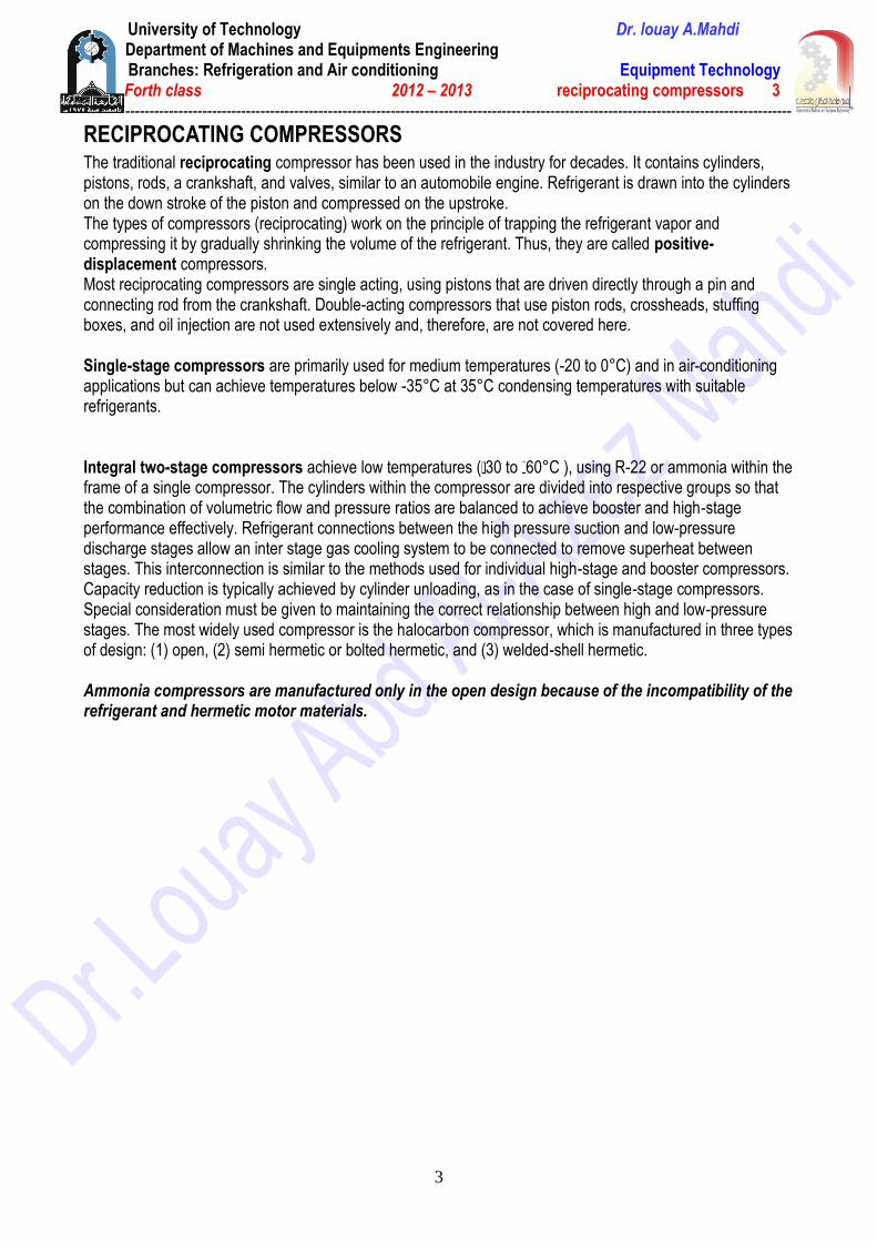
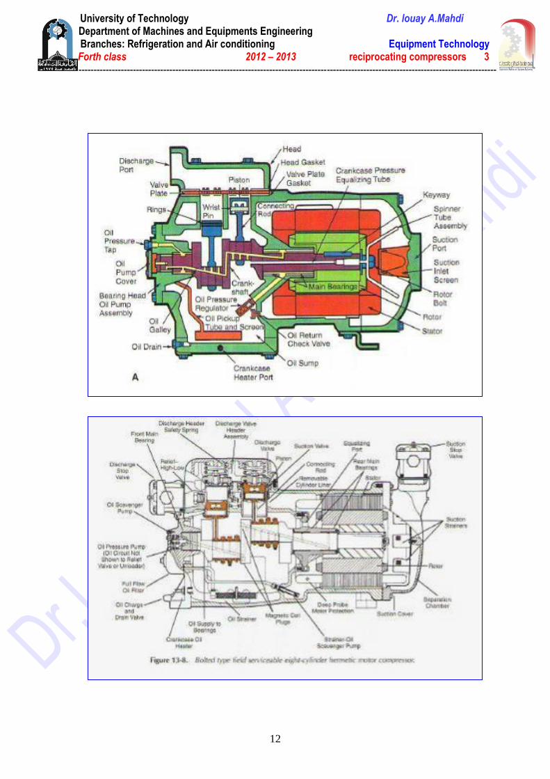
RECIPROCATING COMPRESSORS The traditional reciprocating compressor has been used in the industry for decades. It contains cylinders, pistons, rods, a crankshaft, and valves, similar to an automobile engine. Refrigerant is drawn into the cylinders on the down stroke of the piston and compressed on the upstroke. The types of compressors (reciprocating) work on the principle of trapping the refrigerant vapor and compressing it by gradually shrinking the volume of the refrigerant. Thus, they are called positive-displacement compressors. Most reciprocating compressors are single acting, using pistons that are driven directly through a pin and connecting rod from the crankshaft. Double-acting compressors that use piston rods, crossheads, stuffing boxes, and oil injection are not used extensively and, therefore, are not covered here. Single-stage compressors are primarily used for medium temperatures (-20 to 0°C) and in air-conditioning applications but can achieve temperatures below -35°C at 35°C condensing temperatures with suitable refrigerants. Integral two-stage compressors achieve low temperatures ( 30 to 60°C ), using R-22 or ammonia within the frame of a single compressor. The cylinders within the compressor are divided into respective groups so that the combination of volumetric flow and pressure ratios are balanced to achieve booster and high-stage performance effectively. Refrigerant connections between the high pressure suction and low-pressure discharge stages allow an inter stage gas cooling system to be connected to remove superheat between stages. This interconnection is similar to the methods used for individual high-stage and booster compressors. Capacity reduction is typically achieved by cylinder unloading, as in the case of single-stage compressors. Special consideration must be given to maintaining the correct relationship between high and low-pressure stages. The most widely used compressor is the halocarbon compressor, which is manufactured in three types of design: (1) open, (2) semi hermetic or bolted hermetic, and (3) welded-shell hermetic. Ammonia compressors are manufactured only in the open design because of the incompatibility of the refrigerant and hermetic motor materials.

University of Technology Dr. louay A.Mahdi Department of Machines and Equipments Engineering
Branches: Refrigeration and Air conditioning Equipment Technology Forth class 2012 – 2013 reciprocating compressors 3
------------------------------------------------------------------------------------------------------------------------------------------
4
Features Crankcases. in a welded hermetic compressor, the cylinder block, is usually of cast iron. Crankshafts. are made of either forged steel with hardened bearing surfaces finished or iron castings. Main Bearings. Main bearings are made of steel-backed Babbitt, steel backed or solid bronze, or aluminum.
Connecting Rods and Eccentric Straps. Connecting rods have the large end split and a bolted cap for assembly. Un split eccentric straps require the crankshaft to be passed through the big bore at assembly. Rods or straps are of steel, aluminum, bronze, nodular iron, or gray iron. Steel or iron rods often require inserts of such bearing material as steel-backed Babbitt or bronze, while aluminum and bronze rods can bear directly on the crankpin and piston pin. Piston, Piston Ring, and Piston Pin. Pistons are usually made of cast iron or aluminum. Suction and Discharge Valves. The most important components in the reciprocating compressor are the suction and discharge valves. Successful designs provide long life and low-pressure loss. The life of a properly made and correctly applied valve is determined by the motion and stress it undergoes in performing its function. Excessive pressure loss across the valve results from high gas velocities, poor mechanical action, or both. For design purposes, gas velocity is defined as being equal to the bore area multiplied by the average piston speed and divided by the valve area. Permissible gas velocity through the restricted areas of the valve is left to the discretion of the designer and depends on the level of volumetric efficiency and performance desired. In general, designs with velocities up to 60 m/s with ammonia and up to 45 m/s with R-22 have been successful. A valve should meet the following requirements:
large flow areas with shortest possible path Straight gas flow path, minimum directional changes Low valve mass combined with low lift for quick action Symmetry of design with minimum pressure imbalance Minimum clearance volume Durability Low cost Tight sealing at ports Minimum valve flutter
Here are some advantages and disadvantages of reciprocating compressor. Advantages Disadvantages Simple design, easy to install Higher maintenance cost Lower initial cost Many moving parts Large range of horsepower Potential for vibration problems Special machines can reach extremely high pressure Foundation may be required depending on size Two stages models offer the highest efficiency Many are not designed to run at full capacity
University of Technology Dr. louay A.Mahdi Department of Machines and Equipments Engineering
Branches: Refrigeration and Air conditioning Equipment Technology Forth class 2012 – 2013 reciprocating compressors 3
------------------------------------------------------------------------------------------------------------------------------------------
5
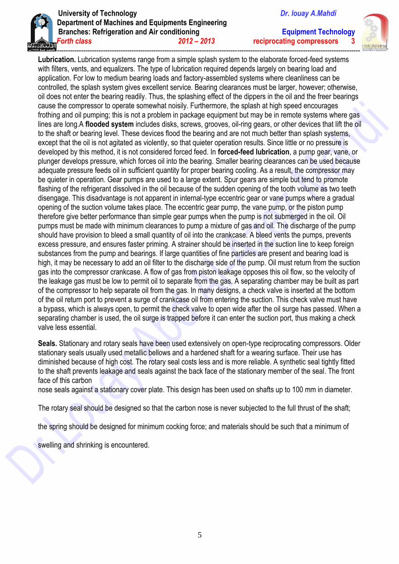
Lubrication. Lubrication systems range from a simple splash system to the elaborate forced-feed systems with filters, vents, and equalizers. The type of lubrication required depends largely on bearing load and application. For low to medium bearing loads and factory-assembled systems where cleanliness can be controlled, the splash system gives excellent service. Bearing clearances must be larger, however; otherwise, oil does not enter the bearing readily. Thus, the splashing effect of the dippers in the oil and the freer bearings cause the compressor to operate somewhat noisily. Furthermore, the splash at high speed encourages frothing and oil pumping; this is not a problem in package equipment but may be in remote systems where gas lines are long.A flooded system includes disks, screws, grooves, oil-ring gears, or other devices that lift the oil to the shaft or bearing level. These devices flood the bearing and are not much better than splash systems, except that the oil is not agitated as violently, so that quieter operation results. Since little or no pressure is developed by this method, it is not considered forced feed. In forced-feed lubrication, a pump gear, vane, or plunger develops pressure, which forces oil into the bearing. Smaller bearing clearances can be used because adequate pressure feeds oil in sufficient quantity for proper bearing cooling. As a result, the compressor may be quieter in operation. Gear pumps are used to a large extent. Spur gears are simple but tend to promote flashing of the refrigerant dissolved in the oil because of the sudden opening of the tooth volume as two teeth disengage. This disadvantage is not apparent in internal-type eccentric gear or vane pumps where a gradual opening of the suction volume takes place. The eccentric gear pump, the vane pump, or the piston pump therefore give better performance than simple gear pumps when the pump is not submerged in the oil. Oil pumps must be made with minimum clearances to pump a mixture of gas and oil. The discharge of the pump should have provision to bleed a small quantity of oil into the crankcase. A bleed vents the pumps, prevents excess pressure, and ensures faster priming. A strainer should be inserted in the suction line to keep foreign substances from the pump and bearings. If large quantities of fine particles are present and bearing load is high, it may be necessary to add an oil filter to the discharge side of the pump. Oil must return from the suction gas into the compressor crankcase. A flow of gas from piston leakage opposes this oil flow, so the velocity of the leakage gas must be low to permit oil to separate from the gas. A separating chamber may be built as part of the compressor to help separate oil from the gas. In many designs, a check valve is inserted at the bottom of the oil return port to prevent a surge of crankcase oil from entering the suction. This check valve must have a bypass, which is always open, to permit the check valve to open wide after the oil surge has passed. When a separating chamber is used, the oil surge is trapped before it can enter the suction port, thus making a check valve less essential.
Seals. Stationary and rotary seals have been used extensively on open-type reciprocating compressors. Older stationary seals usually used metallic bellows and a hardened shaft for a wearing surface. Their use has diminished because of high cost. The rotary seal costs less and is more reliable. A synthetic seal tightly fitted to the shaft prevents leakage and seals against the back face of the stationary member of the seal. The front face of this carbon nose seals against a stationary cover plate. This design has been used on shafts up to 100 mm in diameter.
The rotary seal should be designed so that the carbon nose is never subjected to the full thrust of the shaft;
the spring should be designed for minimum cocking force; and materials should be such that a minimum of
swelling and shrinking is encountered.
University of Technology Dr. louay A.Mahdi Department of Machines and Equipments Engineering
Branches: Refrigeration and Air conditioning Equipment Technology Forth class 2012 – 2013 reciprocating compressors 3
------------------------------------------------------------------------------------------------------------------------------------------
6
Special Devices Capacity Control. An ideal capacity control system would have the following operating characteristics (not all of these benefits can occur simultaneously):
Continuous adjustment to load Full-load efficiency unaffected by the control No loss in efficiency at part load Reduction of starting torque No reduction in compressor reliability No reduction of compressor operating range No increase in compressor vibration and sound level at part load
Capacity control may be obtained by: (1) Controlling suction pressure by throttling; (2) Controlling discharge pressure; (3) Returning discharge gas to suction; (4) Adding re expansion volume; (5) Changing the stroke; (6) Opening a cylinder discharge port to suction while closing the port to discharge manifold; (7) Changing compressor speed; (8) Closing off cylinder inlet, (9) Holding the suction valve open.
The most commonly used methods are opening the suction valves by some external force, gas bypassing within the compressor, and gas bypassing outside the compressor. When capacity control compressors are used, system design becomes more important and the following must be considered:
Possible increase in compressor vibration and sound level at unloaded conditions Minimum operating conditions as limited by discharge or motor temperatures (or both) at part-load
conditions Good oil return at minimum operating conditions when fully unloaded Rapid cycling of unloaders Refrigerant feed device capable of controlling at minimum capacity
Crankcase Heaters. During shutdown, refrigerants tend to migrate to the coldest part of the refrigeration system. In cold weather, the compressor oil sump could be the coldest area. When the refrigerant charge is large enough to dilute the oil excessively and cause flooded starts, a crankcase heater should be used. The heater should maintain the oil at least 10 K above the rest of the system at shutdown and well below the breakdown temperature of the oil at any time.
Application To operate through the entire range of conditions for which the compressor was designed and to obtain the desired service life, it is important that the mating components in the system be correctly designed and selected. Suction superheat must be controlled, lubricant must return to the compressor, and adequate protection must be provided against abnormal conditions.
Automatic Oil Separators. Oil separators are used most often to reduce the amount of oil discharged into the system by the compressor and to return oil to the crankcase. They are recommended for all field-erected systems and on packaged equipment where lubricant contamination will have a negative effect on evaporator capacity and/or where lubricant return at reduced capacity is marginal.
University of Technology Dr. louay A.Mahdi Department of Machines and Equipments Engineering
Branches: Refrigeration and Air conditioning Equipment Technology Forth class 2012 – 2013 reciprocating compressors 3
------------------------------------------------------------------------------------------------------------------------------------------
7
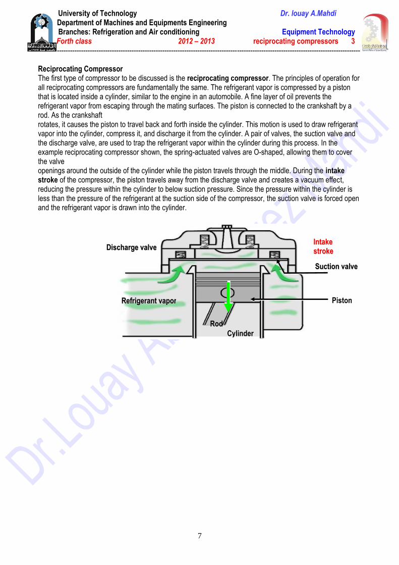
Reciprocating Compressor The first type of compressor to be discussed is the reciprocating compressor. The principles of operation for all reciprocating compressors are fundamentally the same. The refrigerant vapor is compressed by a piston that is located inside a cylinder, similar to the engine in an automobile. A fine layer of oil prevents the refrigerant vapor from escaping through the mating surfaces. The piston is connected to the crankshaft by a rod. As the crankshaft rotates, it causes the piston to travel back and forth inside the cylinder. This motion is used to draw refrigerant vapor into the cylinder, compress it, and discharge it from the cylinder. A pair of valves, the suction valve and the discharge valve, are used to trap the refrigerant vapor within the cylinder during this process. In the example reciprocating compressor shown, the spring-actuated valves are O-shaped, allowing them to cover the valve openings around the outside of the cylinder while the piston travels through the middle. During the intake stroke of the compressor, the piston travels away from the discharge valve and creates a vacuum effect, reducing the pressure within the cylinder to below suction pressure. Since the pressure within the cylinder is less than the pressure of the refrigerant at the suction side of the compressor, the suction valve is forced open and the refrigerant vapor is drawn into the cylinder.
Piston RReeffrriiggeerraanntt vvaappoorr
Cylinder
DDiisscchhaarrggee vvaallvvee
Rod
SSuuccttiioonn vvaallvvee
IInnttaakkee
ssttrrookkee
University of Technology Dr. louay A.Mahdi Department of Machines and Equipments Engineering
Branches: Refrigeration and Air conditioning Equipment Technology Forth class 2012 – 2013 reciprocating compressors 3
------------------------------------------------------------------------------------------------------------------------------------------
8
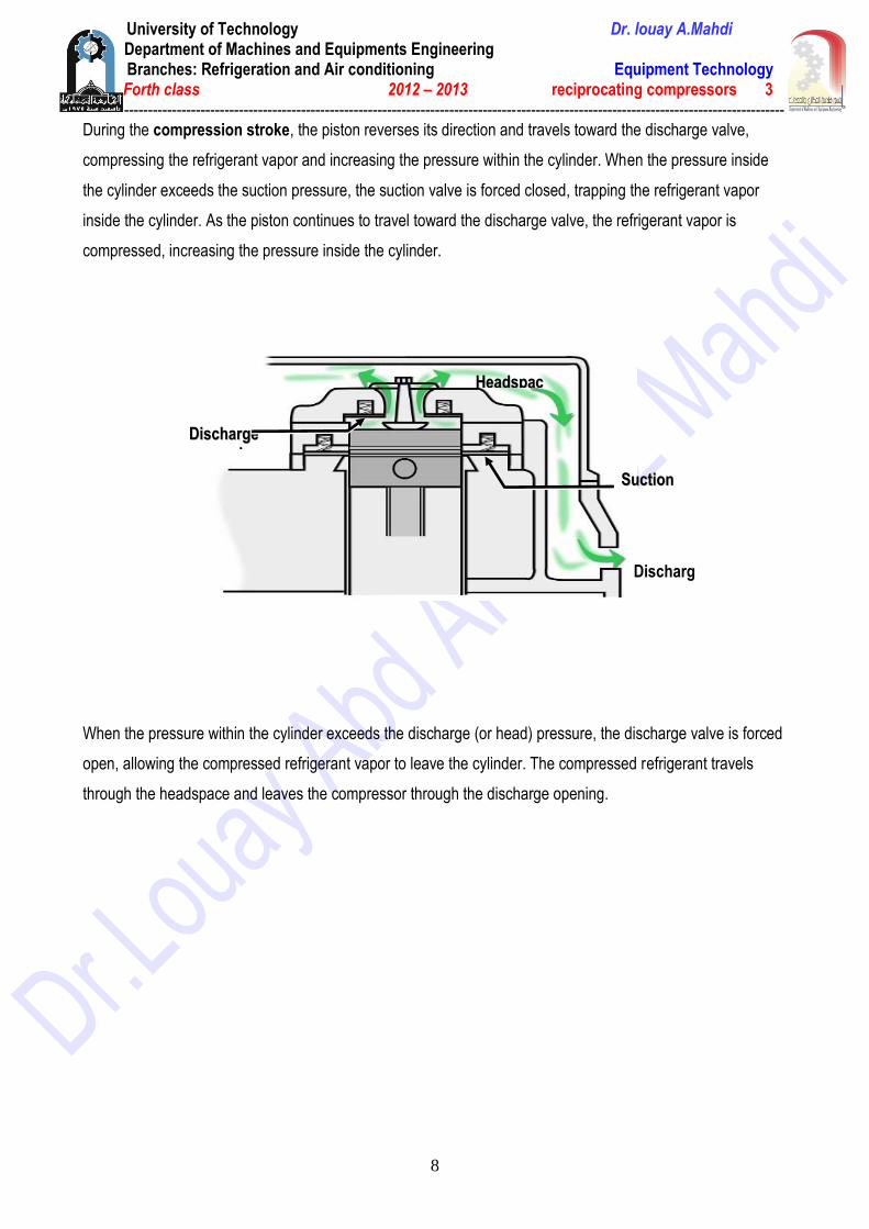
During the compression stroke, the piston reverses its direction and travels toward the discharge valve,
compressing the refrigerant vapor and increasing the pressure within the cylinder. When the pressure inside
the cylinder exceeds the suction pressure, the suction valve is forced closed, trapping the refrigerant vapor
inside the cylinder. As the piston continues to travel toward the discharge valve, the refrigerant vapor is
compressed, increasing the pressure inside the cylinder.
When the pressure within the cylinder exceeds the discharge (or head) pressure, the discharge valve is forced
open, allowing the compressed refrigerant vapor to leave the cylinder. The compressed refrigerant travels
through the headspace and leaves the compressor through the discharge opening.
DDiisscchhaarrggee
vvaallvvee
SSuuccttiioonn
vvaallvvee
Discharge
OOppeenniinngg
HHeeaaddssppaacc
ee
University of Technology Dr. louay A.Mahdi Department of Machines and Equipments Engineering
Branches: Refrigeration and Air conditioning Equipment Technology Forth class 2012 – 2013 reciprocating compressors 3
------------------------------------------------------------------------------------------------------------------------------------------
9
SSuuccttiioonn
ooppeenniinngg
MMoottoorr
PPiissttoonn
CCyylliinnddeerr
CCrraannkksshhaafftt
RRoodd
DDiisscchhaarrggee OOppeenniinngg
HHeeaaddssppaaccee
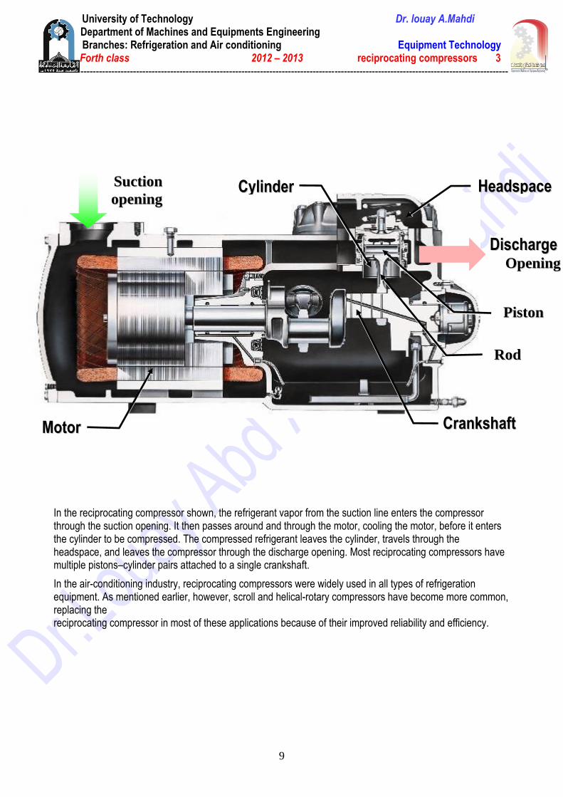
In the reciprocating compressor shown, the refrigerant vapor from the suction line enters the compressor through the suction opening. It then passes around and through the motor, cooling the motor, before it enters the cylinder to be compressed. The compressed refrigerant leaves the cylinder, travels through the headspace, and leaves the compressor through the discharge opening. Most reciprocating compressors have multiple pistons–cylinder pairs attached to a single crankshaft.
In the air-conditioning industry, reciprocating compressors were widely used in all types of refrigeration equipment. As mentioned earlier, however, scroll and helical-rotary compressors have become more common, replacing the reciprocating compressor in most of these applications because of their improved reliability and efficiency.
University of Technology Dr. louay A.Mahdi Department of Machines and Equipments Engineering
Branches: Refrigeration and Air conditioning Equipment Technology Forth class 2012 – 2013 reciprocating compressors 3
------------------------------------------------------------------------------------------------------------------------------------------
10
CCoommpprreessssoorr CCaappaacciittyy CCoonnttrrooll The capacity of a compressor is defined by the volume of evaporated refrigerant that can be compressed within a given time period. The compressor needs a method of capacity control in order to match the ever-changing load on the system.
Methods of Compressor Unloading Reciprocating Cylinder Unloaders
Capacity control is commonly accomplished by unloading the compressor. The method used for unloading generally depends on the type of compressor.
Many reciprocating compressors use cylinder unloaders or compressors could use variable speed to control their capacity.
Cylinder Unloaders
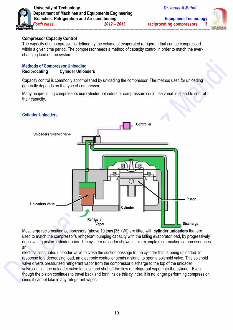
Most large reciprocating compressors (above 10 tons [35 kW]) are fitted with cylinder unloaders that are used to match the compressor’s refrigerant pumping capacity with the falling evaporator load, by progressively deactivating piston–cylinder pairs. The cylinder unloader shown in this example reciprocating compressor uses an electrically-actuated unloader valve to close the suction passage to the cylinder that is being unloaded. In response to a decreasing load, an electronic controller sends a signal to open a solenoid valve. This solenoid valve diverts pressurized refrigerant vapor from the compressor discharge to the top of the unloader valve,causing the unloader valve to close and shut off the flow of refrigerant vapor into the cylinder. Even though the piston continues to travel back and forth inside this cylinder, it is no longer performing compression since it cannot take in any refrigerant vapor.
UUnnllooaaddeerrss Valve
RReeffrriiggeerraanntt
VVaappoorr DDiisscchhaarrggee
UUnnllooaaddeerrss Solenoid valve
Controller
CCyylliinnddeerr
PPiissttoonn
University of Technology Dr. louay A.Mahdi Department of Machines and Equipments Engineering
Branches: Refrigeration and Air conditioning Equipment Technology Forth class 2012 – 2013 reciprocating compressors 3
------------------------------------------------------------------------------------------------------------------------------------------
11
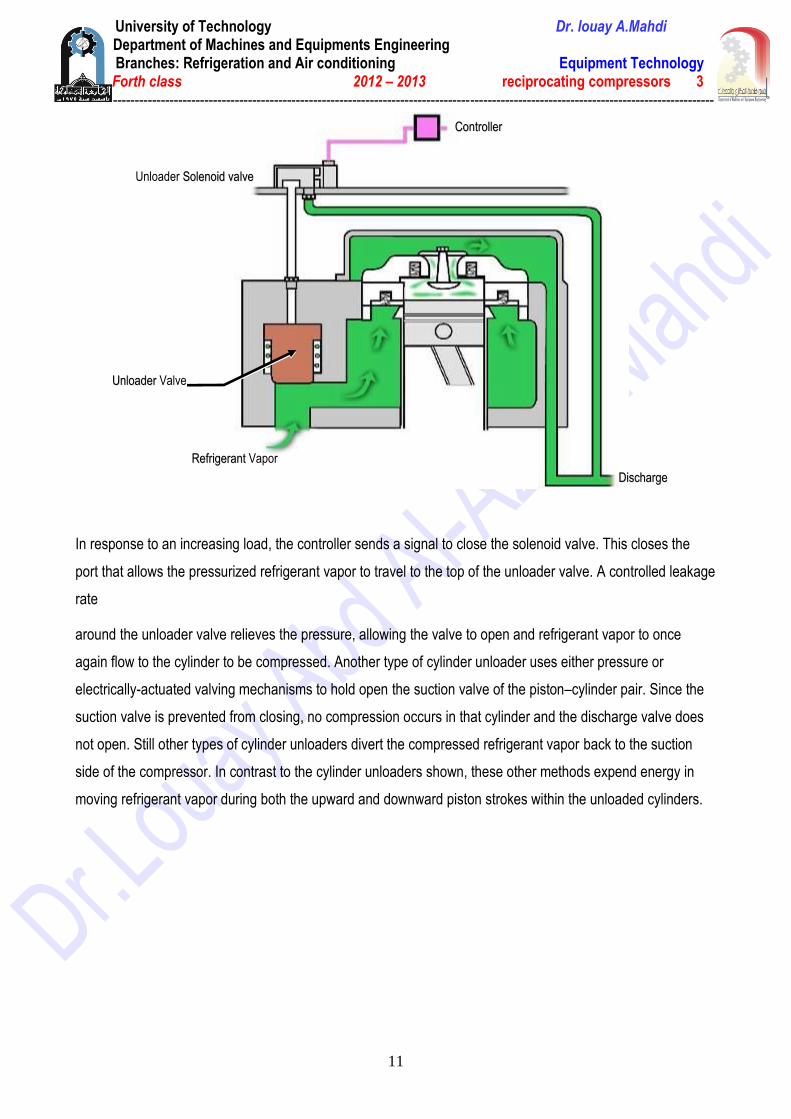
In response to an increasing load, the controller sends a signal to close the solenoid valve. This closes the
port that allows the pressurized refrigerant vapor to travel to the top of the unloader valve. A controlled leakage
rate
around the unloader valve relieves the pressure, allowing the valve to open and refrigerant vapor to once
again flow to the cylinder to be compressed. Another type of cylinder unloader uses either pressure or
electrically-actuated valving mechanisms to hold open the suction valve of the piston–cylinder pair. Since the
suction valve is prevented from closing, no compression occurs in that cylinder and the discharge valve does
not open. Still other types of cylinder unloaders divert the compressed refrigerant vapor back to the suction
side of the compressor. In contrast to the cylinder unloaders shown, these other methods expend energy in
moving refrigerant vapor during both the upward and downward piston strokes within the unloaded cylinders.
UUnnllooaaddeerr Valve
Unloader SSoolleennooiidd vvaallvvee
CCoonnttrroolllleerr
DDiisscchhaarrggee
RReeffrriiggeerraanntt Vapor
University of Technology Dr. louay A.Mahdi Department of Machines and Equipments Engineering
Branches: Refrigeration and Air conditioning Equipment Technology Forth class 2012 – 2013 reciprocating compressors 3
------------------------------------------------------------------------------------------------------------------------------------------
12

University of Technology Dr. louay A.Mahdi Department of Machines and Equipments Engineering
Branches: Refrigeration and Air conditioning Equipment Technology Forth class 2012 – 2013 rolling piston compressors 4
------------------------------------------------------------------------------------------------------------------------------------------
1
Rolling piston – Fixed vane
University of Technology Dr. louay A.Mahdi Department of Machines and Equipments Engineering
Branches: Refrigeration and Air conditioning Equipment Technology Forth class 2012 – 2013 rolling piston compressors 4
------------------------------------------------------------------------------------------------------------------------------------------
2
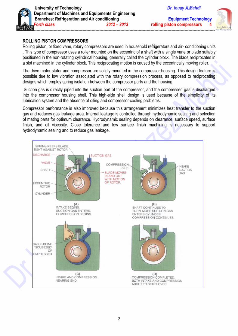
ROLLING PISTON COMPRESSORS Rolling piston, or fixed vane, rotary compressors are used in household refrigerators and air- conditioning units . This type of compressor uses a roller mounted on the eccentric of a shaft with a single vane or blade suitably positioned in the non-rotating cylindrical housing, generally called the cylinder block. The blade reciprocates in a slot machined in the cylinder block. This reciprocating motion is caused by the eccentrically moving roller.
The drive motor stator and compressor are solidly mounted in the compressor housing. This design feature is possible due to low vibration associated with the rotary compression process, as opposed to reciprocating designs which employ spring isolation between the compressor parts and the housing.
Suction gas is directly piped into the suction port of the compressor, and the compressed gas is discharged into the compressor housing shell. This high-side shell design is used because of the simplicity of its lubrication system and the absence of oiling and compressor cooling problems.
Compressor performance is also improved because this arrangement minimizes heat transfer to the suction gas and reduces gas leakage area. Internal leakage is controlled through hydrodynamic sealing and selection of mating parts for optimum clearance. Hydrodynamic sealing depends on clearance, surface speed, surface finish, and oil viscosity. Close tolerance and low surface finish machining is necessary to support hydrodynamic sealing and to reduce gas leakage.
University of Technology Dr. louay A.Mahdi Department of Machines and Equipments Engineering
Branches: Refrigeration and Air conditioning Equipment Technology Forth class 2012 – 2013 rolling piston compressors 4
------------------------------------------------------------------------------------------------------------------------------------------
3
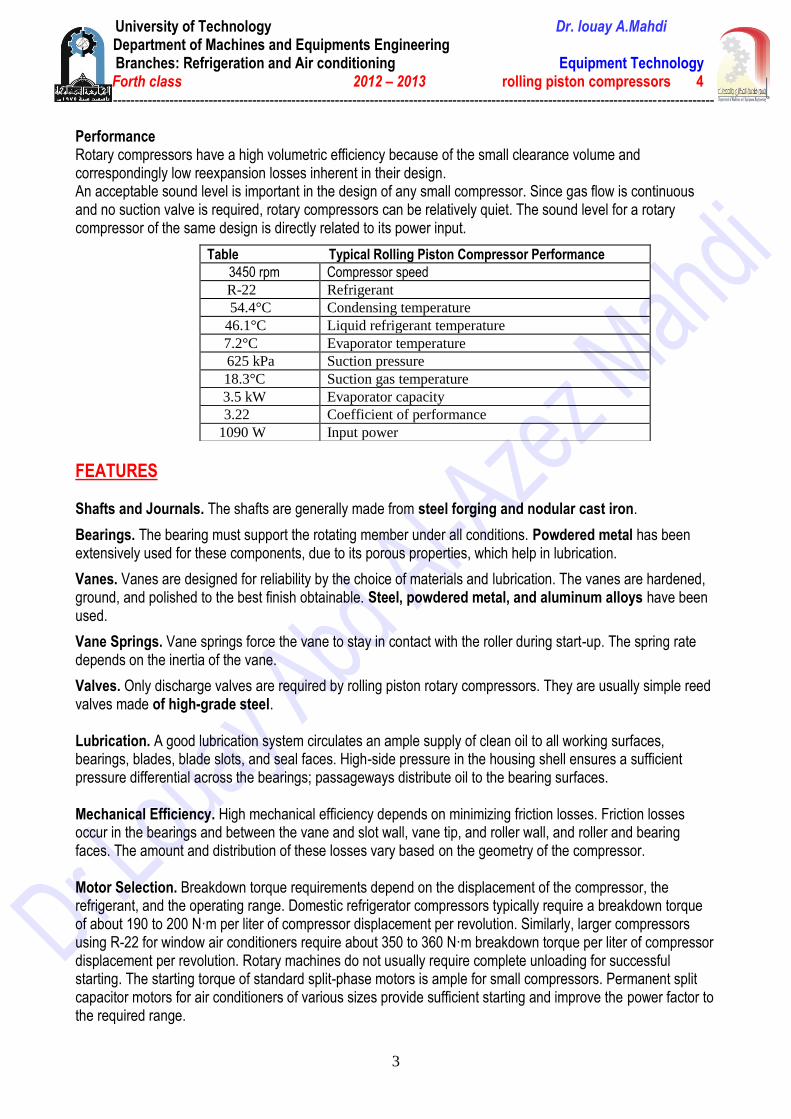
Performance Rotary compressors have a high volumetric efficiency because of the small clearance volume and correspondingly low reexpansion losses inherent in their design. An acceptable sound level is important in the design of any small compressor. Since gas flow is continuous and no suction valve is required, rotary compressors can be relatively quiet. The sound level for a rotary compressor of the same design is directly related to its power input.
FEATURES Shafts and Journals. The shafts are generally made from steel forging and nodular cast iron.
Bearings. The bearing must support the rotating member under all conditions. Powdered metal has been extensively used for these components, due to its porous properties, which help in lubrication.
Vanes. Vanes are designed for reliability by the choice of materials and lubrication. The vanes are hardened, ground, and polished to the best finish obtainable. Steel, powdered metal, and aluminum alloys have been used.
Vane Springs. Vane springs force the vane to stay in contact with the roller during start-up. The spring rate depends on the inertia of the vane.
Valves. Only discharge valves are required by rolling piston rotary compressors. They are usually simple reed valves made of high-grade steel. Lubrication. A good lubrication system circulates an ample supply of clean oil to all working surfaces, bearings, blades, blade slots, and seal faces. High-side pressure in the housing shell ensures a sufficient pressure differential across the bearings; passageways distribute oil to the bearing surfaces. Mechanical Efficiency. High mechanical efficiency depends on minimizing friction losses. Friction losses occur in the bearings and between the vane and slot wall, vane tip, and roller wall, and roller and bearing faces. The amount and distribution of these losses vary based on the geometry of the compressor. Motor Selection. Breakdown torque requirements depend on the displacement of the compressor, the refrigerant, and the operating range. Domestic refrigerator compressors typically require a breakdown torque of about 190 to 200 N·m per liter of compressor displacement per revolution. Similarly, larger compressors using R-22 for window air conditioners require about 350 to 360 N·m breakdown torque per liter of compressor displacement per revolution. Rotary machines do not usually require complete unloading for successful starting. The starting torque of standard split-phase motors is ample for small compressors. Permanent split capacitor motors for air conditioners of various sizes provide sufficient starting and improve the power factor to the required range.
Table Typical Rolling Piston Compressor Performance
Compressor speed 3450 rpm
Refrigerant R-22
Condensing temperature 54.4°C
Liquid refrigerant temperature 46.1°C
Evaporator temperature 7.2°C
Suction pressure 625 kPa
Suction gas temperature 18.3°C
Evaporator capacity 3.5 kW
Coefficient of performance 3.22
Input power 1090 W

University of Technology Dr. louay A.Mahdi Department of Machines and Equipments Engineering
Branches: Refrigeration and Air conditioning Equipment Technology Forth class 2012 – 2013 rolling piston compressors 4
------------------------------------------------------------------------------------------------------------------------------------------
4
Advantages Disadvantages Simple design High rotational speed Low to medium initial and maintenance cost shorter life expectancy than any other designs Two-stages design provide good efficiencies Single-stage designs have lower efficiency Easy to install Difficulty with dirty environment Few moving parts
University of Technology Dr. louay A.Mahdi Department of Machines and Equipments Engineering
Branches: Refrigeration and Air conditioning Equipment Technology Forth class 2012 – 2013 rolling piston compressors 4
------------------------------------------------------------------------------------------------------------------------------------------
5
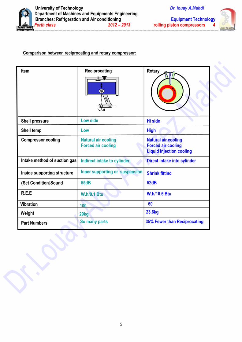
Comparison between reciprocating and rotary compressor:
23.6kg 29kg Weight
35% Fewer than Reciprocating So many parts Part Numbers
60 100 Vibration
10.6 Btu/h.W 9.1 Btu/h.W E.E.R
52dB 55dB Sound (Set Condition)
Shrink fitting Inner supporting or suspension Inside supporting structure
Direct intake into cylinder Indirect intake to cylinder Intake method of suction gas
Natural air cooling Forced air cooling Liquid injection cooling
Natural air cooling Forced air cooling
Compressor cooling
High Low Shell temp
Hi side Low side Shell pressure
Rotary Reciprocating
Item
University of Technology Dr. louay A.Mahdi Department of Machines and Equipments Engineering
Branches: Refrigeration and Air conditioning Equipment Technology Forth class 2012 – 2013 scroll compressors 5
------------------------------------------------------------------------------------------------------------------------------------------
1
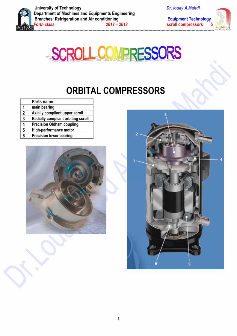
ORBITAL COMPRESSORS
Parts name
1 main bearing
2 Axially compliant upper scroll
3 Radially compliant orbiting scroll
4 Precision Oldham coupling
5 High-performance motor
6 Precision lower bearing
University of Technology Dr. louay A.Mahdi Department of Machines and Equipments Engineering
Branches: Refrigeration and Air conditioning Equipment Technology Forth class 2012 – 2013 scroll compressors 5
------------------------------------------------------------------------------------------------------------------------------------------
2
University of Technology Dr. louay A.Mahdi Department of Machines and Equipments Engineering
Branches: Refrigeration and Air conditioning Equipment Technology Forth class 2012 – 2013 scroll compressors 5
------------------------------------------------------------------------------------------------------------------------------------------
3
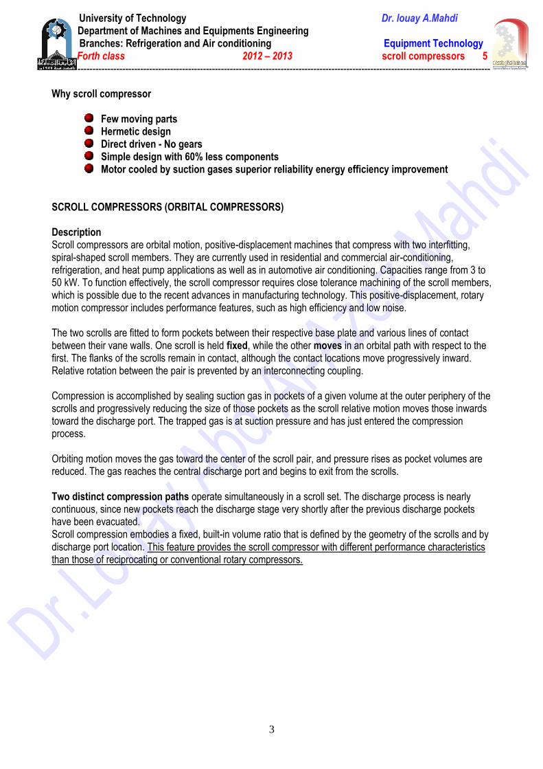
Why scroll compressor
Few moving parts Hermetic design Direct driven - No gears Simple design with 60% less components Motor cooled by suction gases superior reliability energy efficiency improvement
SCROLL COMPRESSORS (ORBITAL COMPRESSORS) Description Scroll compressors are orbital motion, positive-displacement machines that compress with two interfitting, spiral-shaped scroll members. They are currently used in residential and commercial air-conditioning, refrigeration, and heat pump applications as well as in automotive air conditioning. Capacities range from 3 to 50 kW. To function effectively, the scroll compressor requires close tolerance machining of the scroll members, which is possible due to the recent advances in manufacturing technology. This positive-displacement, rotary motion compressor includes performance features, such as high efficiency and low noise. The two scrolls are fitted to form pockets between their respective base plate and various lines of contact between their vane walls. One scroll is held fixed, while the other moves in an orbital path with respect to the first. The flanks of the scrolls remain in contact, although the contact locations move progressively inward. Relative rotation between the pair is prevented by an interconnecting coupling. Compression is accomplished by sealing suction gas in pockets of a given volume at the outer periphery of the scrolls and progressively reducing the size of those pockets as the scroll relative motion moves those inwards toward the discharge port. The trapped gas is at suction pressure and has just entered the compression process. Orbiting motion moves the gas toward the center of the scroll pair, and pressure rises as pocket volumes are reduced. The gas reaches the central discharge port and begins to exit from the scrolls. Two distinct compression paths operate simultaneously in a scroll set. The discharge process is nearly continuous, since new pockets reach the discharge stage very shortly after the previous discharge pockets have been evacuated. Scroll compression embodies a fixed, built-in volume ratio that is defined by the geometry of the scrolls and by discharge port location. This feature provides the scroll compressor with different performance characteristics than those of reciprocating or conventional rotary compressors.

University of Technology Dr. louay A.Mahdi Department of Machines and Equipments Engineering
Branches: Refrigeration and Air conditioning Equipment Technology Forth class 2012 – 2013 scroll compressors 5
------------------------------------------------------------------------------------------------------------------------------------------
4
Features: Scroll Members. Gas sealing is critical to the performance advantage of scroll compressors. Sealing within the scroll set must be accomplished at the flank contact locations and between the vane tips and bases of the intermeshed scroll pair. Tip/base sealing is generally considered more critical than flank sealing. The method used to seal the scroll members tends to separate scroll compressors into compliant and noncompliant designs. Noncompliant Designs. In designs lacking compliance, the orbiting scroll takes a fixed orbital path. In the radial direction, sealing small irregularities between the vane flanks (due to flank machining variation) can be accomplished with oil flooding. In the axial direction, the position of both scrolls remains fixed, and flexible seals fitted into machined grooves on the tips of both scrolls accomplish tip sealing. The seals are pressure loaded to enhance uniform contact. Radial Compliance. This feature enhances flank sealing and allows the orbiting scroll to follow a flexible path defined by its own contact with the fixed scroll. In one type of radial compliance, a sliding “Unloaders” bushing is fitted onto the crankshaft eccentric pin in such a way that it directs the radial motion of the orbiting scroll. The orbiting scroll is mounted over this bushing through adrive bearing, and the scroll may now move radially in and out to accommodate variations in orbit radius caused by machining and assembly discrepancies. This feature tends to keep the flanks constantly in contact, and reduces impact on the flanks that can result from intermittent contact. Sufficient clearance in the pin/Unloaders assembly allows the scroll flanks to separate fully when desired. In some designs, the mass of the orbiting scroll is selected so that Centrifugal force overcomes radial gas compression forces that would otherwise keep the flanks separated. In some other designs, the drive is designed so that the influence of centrifugal force is reduced, and the drive force overcomes the radial gas compression force. Radial compliance has the added benefit of increasing resistance to slugging and contaminants, since the orbiting scroll can “unload” to some extent as it encounters obstacles or non uniform hydraulic pressures. Axial Compliance. With this feature, an adjustable axial pressure maintains sealing contact between the scroll tips and bases while running. This pressure is released when the unit is shut down, allowing the compressor to start unloaded and to approach full operational speed before a significant load is encountered. This scheme obviates the use of tip seals, eliminating them as a potential source of wear and leakage. With the scroll tips bearing directly on the opposite base plates and with suitable lubrication, sealing tends to improve over time. Axial compliance can either be implemented on the orbiting scroll or the fixed scroll. The use of axial compliance requires auxiliary sealing of the discharge side with respect to the suction side of the compressor. Antirotation Coupling. To ensure relative orbital motion, the orbiting scroll must not rotate in response to gas loading. This rotation is most commonly accomplished by an Oldham coupling mechanism, which physically connects the scrolls and permits all planar motion, except relative rotation, between them. Bearing System. The bearing system consists of a drive bearing mounted in the orbiting scroll and generally one of two main bearings. The main bearings are either of the cantilevered type (main bearings on same side of the motor as the scrolls) or consist of a main bearing on either side of the motor. All bearing load vectors rotate through a full 360° due to the nature of the drive load. The orbiting scroll is supported axially by a thrust bearing on a housing which is part of the internal frame or is mounted directly to the compressor shell.

University of Technology Dr. louay A.Mahdi Department of Machines and Equipments Engineering
Branches: Refrigeration and Air conditioning Equipment Technology Forth class 2012 – 2013 scroll compressors 5
------------------------------------------------------------------------------------------------------------------------------------------
5
Capacity Control Two different capacity control mechanisms are currently being used by the scroll compressor industry. 1. Variable-Speed Scroll Compressor. Conventional air conditioning uses a constant speed motor to drive the compressor. The variable-speed scroll compressor uses an inverter drive to convert a fixed frequency alternating current into one with adjustable voltage and frequency, which allows the variation of the rotating speed of the compressor motor. The compressor uses either an induction or a permanent magnet motor. Typical operating frequency varies between 15 and 150 Hz. The capacity provided by the machine is nearly directly proportional to its running frequency. Thus, virtually infinite capacity steps are possible for the system with a variable- speed compressor. The variable-speed scroll compressor is now widely used in Japan. 2. Variable-Displacement Scroll Compressor. This capacity control mechanism incorporates porting holes in the fixed scroll member. The control mechanism disconnects or connects compression chambers to the suction side by respectively closing or opening the porting holes. When all porting holes are closed, the compressor runs at full capacity; opening of all porting holes to the suction side yields the smallest capacity. Thus, by opening or closing a different number of porting holes, variable cooling or heating capability is provided to the system. The number of different capacities and the extent of the capacity reduction available is governed by the locations of the ports in reference to full capacity suction seal-off. Performance Scroll technology offers an advantage in performance for a number of reasons. Large suction and discharge ports reduce pressure losses incurred in the suction and discharge processes. Also, physical separation of these processes reduces heat transfer to the suction gas. The absence of valves and reexpansion volumes and the continuous flow process results in high volumetric efficiency over a wide range of operating conditions. Figure 36 illustrates this effect. The built-in volume ratio can be designed for lowest over- or under compression at typical demand conditions (2.5 to 3.5 pressure ratio for air conditioning). Isentropic efficiency in the range of 70% is possible at such pressure ratios, and it remains quite close to the efficiency of other compressor types at high pressure ratio. Scroll compressors offer a flatter capacity versus outdoor ambient curve than reciprocating products, which means that they can more closely approach indoor requirements at high demand conditions. As a result, the heat pump mode requires less supplemental heating; the cooling mode is more comfortable, because cycling is less as demand decreases. Noise and Vibration The scroll compressor inherently possesses a potential for low sound and vibration. It includes a minimal number of moving parts compared to other compressor technologies. Since scroll compression requires no valves, impact noise and vibration are completely eliminated. The presence of a continuous suction-compression-discharge process and low gas pressure pulsation help to keep vibration low. A virtually perfect dynamic balancing of the orbiting scroll inertia with counterweights eliminates possible vibration due to the rotating parts. Also, smooth surface finish and accurate machining of the vane profiles and base plates of both scroll members (requirement for small leakage) aids in minimal impact of the vanes. A typical sound spectrum of the scroll compressor is shown in Most scroll compressors used today are of the hermetic type, which require virtually no maintenance. However, the compressor manufacturer’s operation and application manual should be followed.
University of Technology Dr. louay A.Mahdi Department of Machines and Equipments Engineering
Branches: Refrigeration and Air conditioning Equipment Technology Forth class 2012 – 2013 scroll compressors 5
------------------------------------------------------------------------------------------------------------------------------------------
6
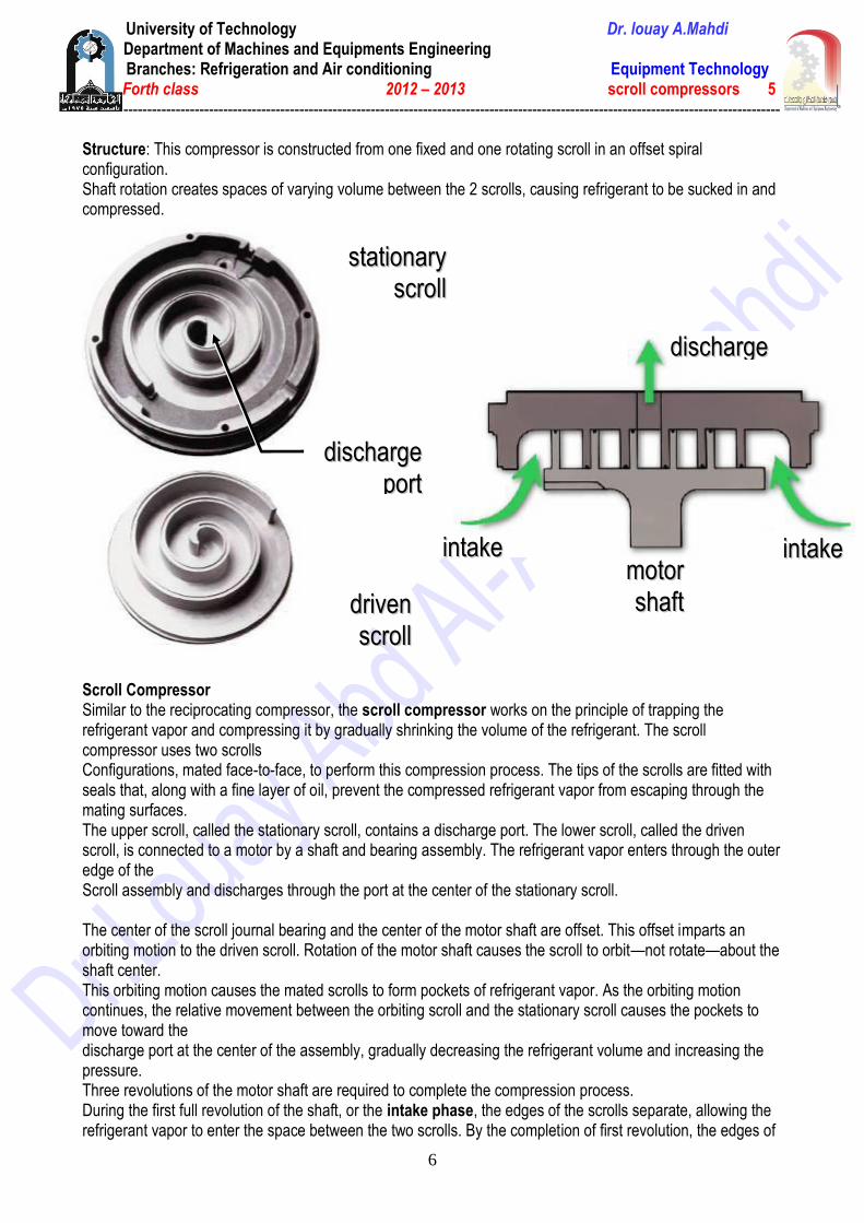
Structure: This compressor is constructed from one fixed and one rotating scroll in an offset spiral configuration. Shaft rotation creates spaces of varying volume between the 2 scrolls, causing refrigerant to be sucked in and compressed.
Scroll Compressor Similar to the reciprocating compressor, the scroll compressor works on the principle of trapping the refrigerant vapor and compressing it by gradually shrinking the volume of the refrigerant. The scroll compressor uses two scrolls Configurations, mated face-to-face, to perform this compression process. The tips of the scrolls are fitted with seals that, along with a fine layer of oil, prevent the compressed refrigerant vapor from escaping through the mating surfaces. The upper scroll, called the stationary scroll, contains a discharge port. The lower scroll, called the driven scroll, is connected to a motor by a shaft and bearing assembly. The refrigerant vapor enters through the outer edge of the Scroll assembly and discharges through the port at the center of the stationary scroll. The center of the scroll journal bearing and the center of the motor shaft are offset. This offset imparts an orbiting motion to the driven scroll. Rotation of the motor shaft causes the scroll to orbit—not rotate—about the shaft center. This orbiting motion causes the mated scrolls to form pockets of refrigerant vapor. As the orbiting motion continues, the relative movement between the orbiting scroll and the stationary scroll causes the pockets to move toward the discharge port at the center of the assembly, gradually decreasing the refrigerant volume and increasing the pressure. Three revolutions of the motor shaft are required to complete the compression process. During the first full revolution of the shaft, or the intake phase, the edges of the scrolls separate, allowing the refrigerant vapor to enter the space between the two scrolls. By the completion of first revolution, the edges of
ssttaattiioonnaarryy
ssccrroollll
ddrriivveenn
ssccrroollll
iinnttaakkee
ddiisscchhaarrggee
iinnttaakkee
ddiisscchhaarrggee
ppoorrtt
mmoottoorr
sshhaafftt

University of Technology Dr. louay A.Mahdi Department of Machines and Equipments Engineering
Branches: Refrigeration and Air conditioning Equipment Technology Forth class 2012 – 2013 scroll compressors 5
------------------------------------------------------------------------------------------------------------------------------------------
7
the scrolls meet again, forming two closed pockets of refrigerant. During the second full revolution, or the compression phase, the volume of each pocket is progressively reduced, increasing the pressure of the trapped refrigerant vapor. Completion of the second revolution produces near maximum compression. During the third full revolution, or the discharge phase, the interior edges of the scrolls separate, releasing the compressed refrigerant through the discharge port. At the completion of the revolution, the volume of each pocket is reduced to zero, forcing the remaining refrigerant vapor out of the scrolls. Looking at the complete cycle, notice that these three phases—intake, compression, and discharge—occur simultaneously in an ongoing sequence. While one pair of these pockets is being formed, another pair is being compressed and a third pair is being discharged.
IInnttaakkee pphhaassee
CCoommpprreessssiioonn pphhaassee
Discharge phase
University of Technology Dr. louay A.Mahdi Department of Machines and Equipments Engineering
Branches: Refrigeration and Air conditioning Equipment Technology Forth class 2012 – 2013 scroll compressors 5
------------------------------------------------------------------------------------------------------------------------------------------
8
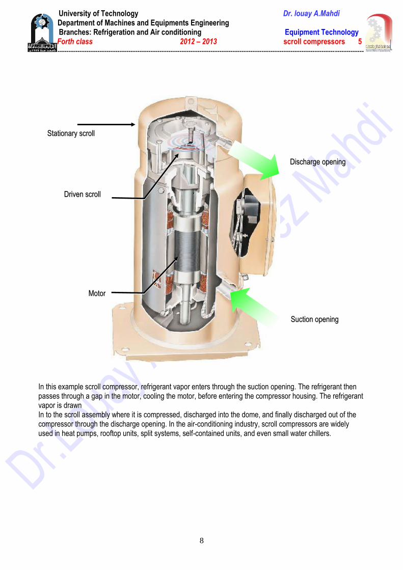
In this example scroll compressor, refrigerant vapor enters through the suction opening. The refrigerant then passes through a gap in the motor, cooling the motor, before entering the compressor housing. The refrigerant vapor is drawn In to the scroll assembly where it is compressed, discharged into the dome, and finally discharged out of the compressor through the discharge opening. In the air-conditioning industry, scroll compressors are widely used in heat pumps, rooftop units, split systems, self-contained units, and even small water chillers.
MMoottoorr
SSuuccttiioonn ooppeenniinngg
DDiisscchhaarrggee ooppeenniinngg
SSttaattiioonnaarryy ssccrroollll
DDrriivveenn ssccrroollll


