Embed Size (px)
Citation preview
Unit 2: Engineering Design Process
Foundations of Technology
1 Sketching and Technical Drawing
Lesson 5: Prototypes and Modeling
ObjectivesStudents learn to:
• Use prototypes and models to ensure quality, efficiency, and productivity of theirfinal product.
• Visualize three-dimensional objects and spaces from different perspectives and analyze their cross sections.

Objectives
• Draw reasonable conclusions about a situation being modeled.
• Explain how design usually requires taking into account not only physical constraints but also economic, political, social, ethical, and aesthetic ones.
Objectives
• Draw and construct representations of two- and three-dimensional geometric objects using a variety of tools.
• Analyze properties and determine attributes of two- and three-dimensional objects.
Vocabulary
• Annotated Sketches: are sketches that include notes or labels, dimensions and/or symbols.
• Technical Drawing: is a visual communication language which is used to communicate how something works or is constructed, includes standard symbols and units of measurement.
Vocabulary
• CAD: computer-aided design.
• Orthographic Projection or Muliti-view: is a way to represent a three dimensional object in two dimensions. Typically, two or more elevations or pictures are produced to represent the entire object – know as multi-view projection.
Vocabulary
• Isometric Projection: is a simple way to show a three dimensional object. By using isometric projection, three sides of a object are shown proportionally. All vertical lines are drawn vertically, and all horizontal lines are drawn at an angle of 30° degrees.
Vocabulary
• Models: are used throughout the Engineering Design Process to make observations and develop predictions, can be conceptual (are abstract models that use language and graphic based representations to convey meaning), mathematical (are abstract models that use the language of mathematics to describe the behavior of the solution) or physical (are three-dimensional models, which represent the solution).
Vocabulary
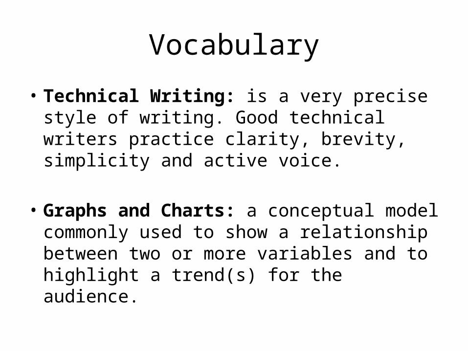
• Technical Writing: is a very precise style of writing. Good technical writers practice clarity, brevity, simplicity and active voice.
• Graphs and Charts: a conceptual model commonly used to show a relationship between two or more variables and to highlight a trend(s) for the audience.
Vocabulary
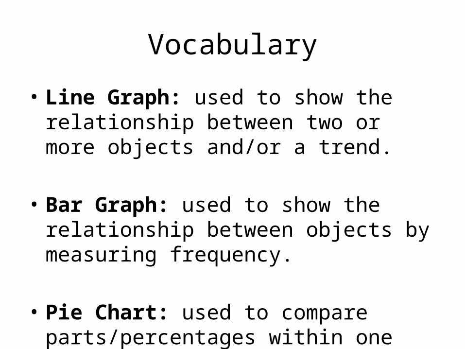
• Line Graph: used to show the relationship between two or more objects and/or a trend.
• Bar Graph: used to show the relationship between objects by measuring frequency.
• Pie Chart: used to compare parts/percentages within one set of data.
Vocabulary
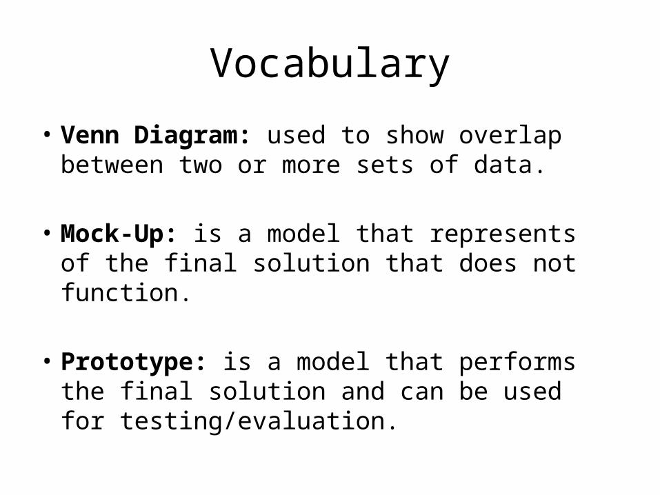
• Venn Diagram: used to show overlap between two or more sets of data.
• Mock-Up: is a model that represents of the final solution that does not function.
• Prototype: is a model that performs the final solution and can be used for testing/evaluation.
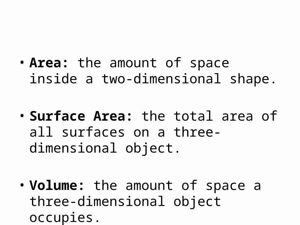
• Area: the amount of space inside a two-dimensional shape.
• Surface Area: the total area of all surfaces on a three-dimensional object.
• Volume: the amount of space a three-dimensional object occupies.
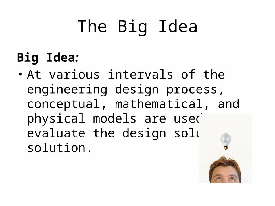
The Big Idea
Big Idea: • At various intervals of the engineering design
process, conceptual, mathematical, and physical models are used to evaluate the design solution. solution.
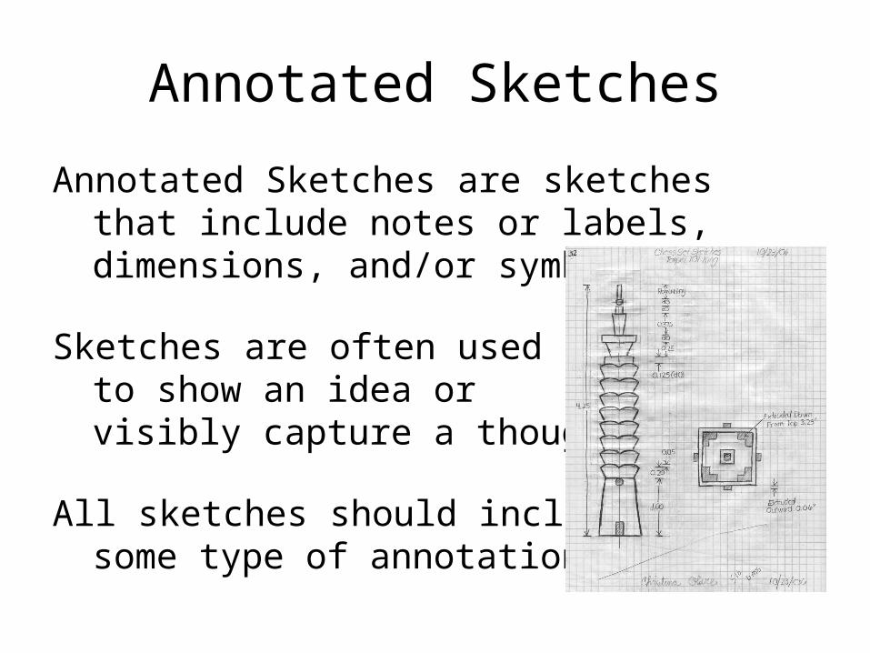
Annotated Sketches
Annotated Sketches are sketches that include notes or labels, dimensions, and/or symbols.
Sketches are often used to show an idea or visibly capture a thought.
All sketches should includesome type of annotation.
Annotated Sketches
Sketching takes practice, but there are some basics to remember:
Use long, light, and flowing lines rather than heavy or short lines.
Sketches are a loose representation of the idea; accuracy is not critical.
Keep your sketches quick; include enough detail to get your idea across.
Use basic shapes to frame the sketch, then add more detail.
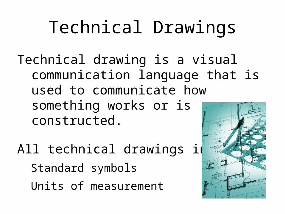
Technical Drawings
Technical drawing is a visual communication language that is used to communicate how something works or is constructed.
All technical drawings include:
Standard symbols
Units of measurement

Technical Drawings
Technical Drawings can be produced using paper and pencil or on a computer using computer-aided design (CAD).
We will use two basics types oftechnical drawings:
Orthographic Projection or
Muliti-view
Isometric projection

Orthographic Projection or Muliti-view
Orthographic projection is a way to represent a three-dimensional object in two dimensions.
Typically, two or more elevations or pictures areproduced to represent the entire object—known as multiview projection
Orthographic Projection or Muliti-view
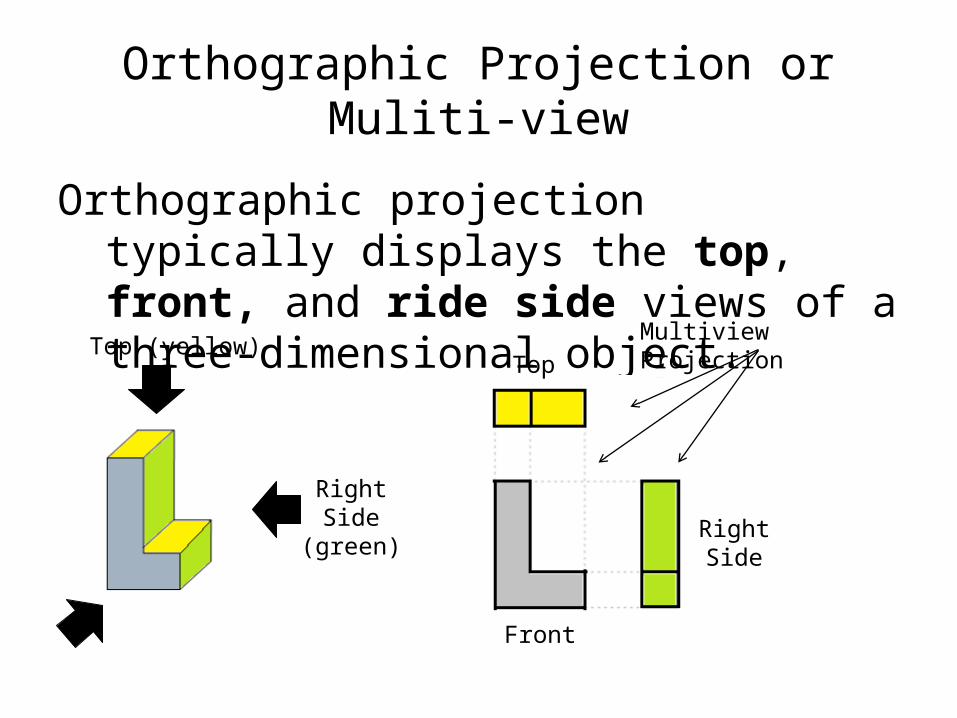
Orthographic projection typically displays the top, front, and ride side views of a three-dimensional object.
Top (yellow)
RightSide
(green)
Top
RightSide
Front
Multiview Projection
Orthographic Projection or Muliti-view
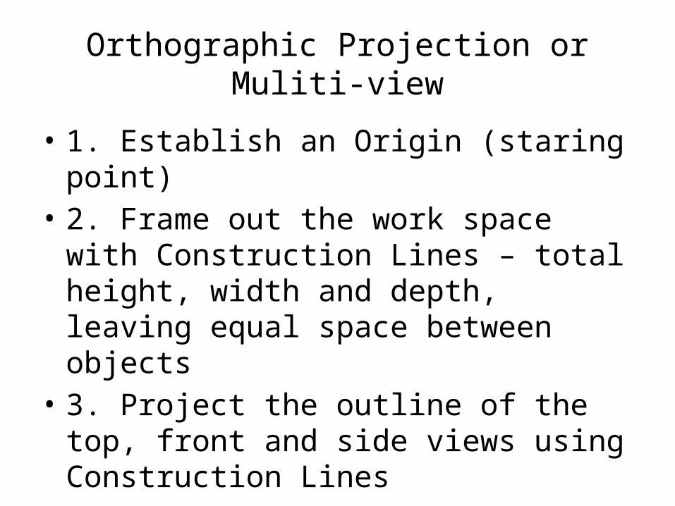
• 1. Establish an Origin (staring point)• 2. Frame out the work space with
Construction Lines – total height, width and depth, leaving equal space between objects
• 3. Project the outline of the top, front and side views using Construction Lines

Orthographic Projection or Muliti-view
• 4. Add a 45° line starting in the upper right hand corner – used to project details between the top and side views
• 5. Add points of interest to the most descriptive view
• 6. Project points of interest using Construction Lines
• 7. Darken all finished lines for each view
Orthographic Projection or Muliti-view
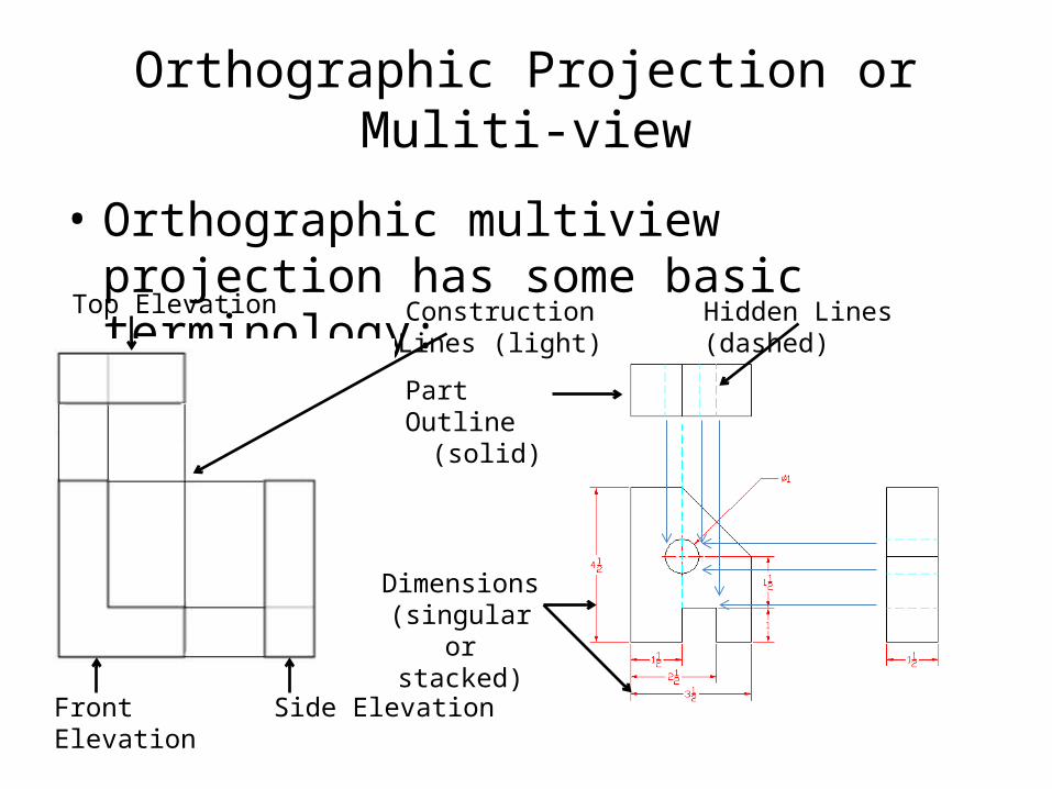
• Orthographic multiview projection has some basic terminology:
Top Elevation
Side ElevationFront Elevation
Construction Lines (light)
Part Outline(solid)
Hidden Lines (dashed)
Dimensions(singular or
stacked)
Orthographic Projection or Muliti-view
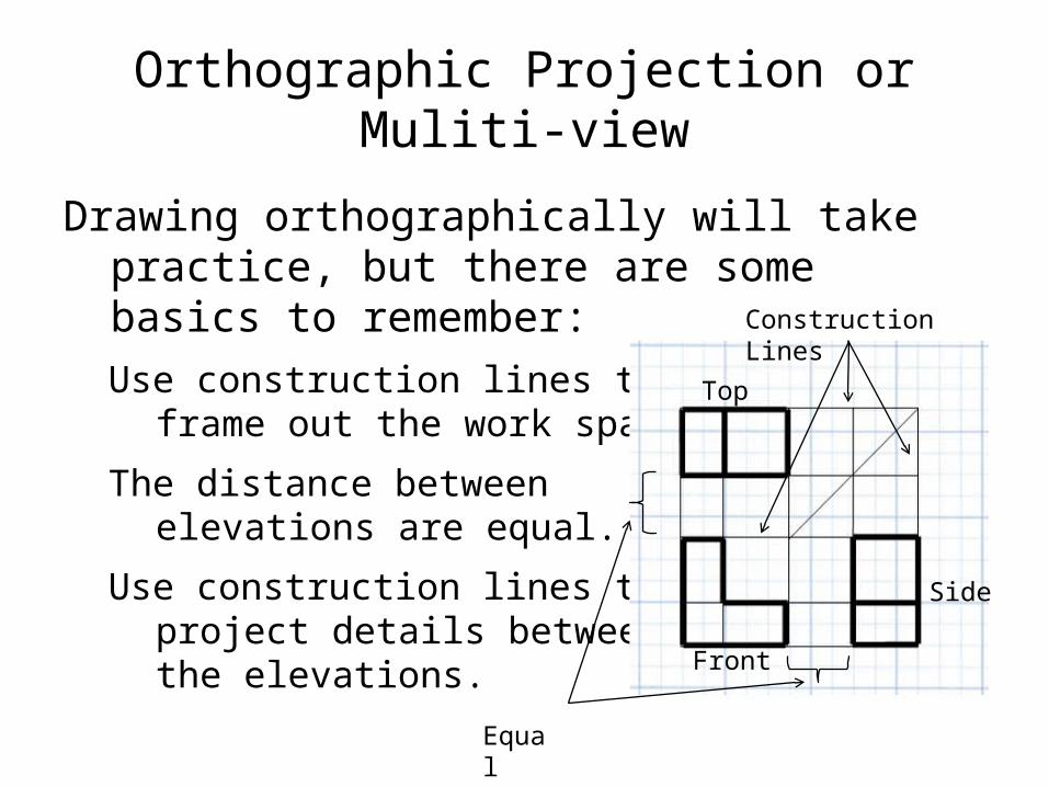
Drawing orthographically will take practice, but there are some basics to remember:
Use construction lines toframe out the work space.
The distance between elevations are equal.
Use construction lines to project details betweenthe elevations.
Construction Lines
Equal
Top
Side
Front
Orthographic Projection or Muliti-view
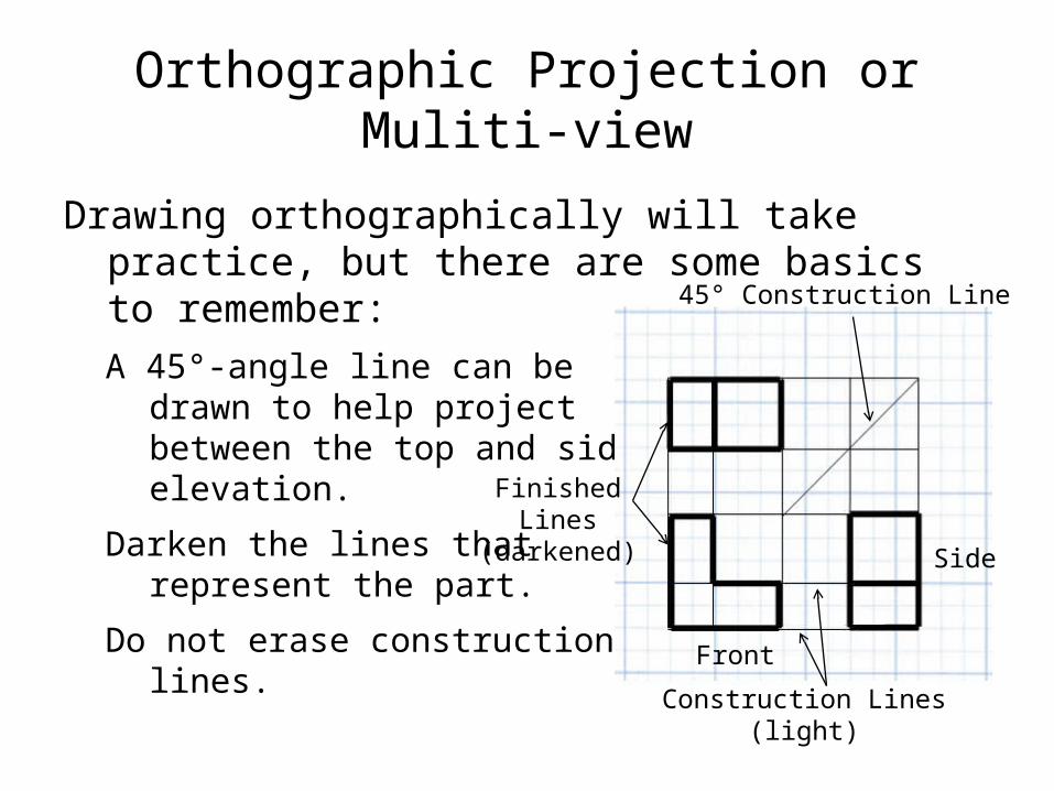
Drawing orthographically will take practice, but there are some basics to remember:
A 45°-angle line can be drawn to help project between the top and sideelevation.
Darken the lines thatrepresent the part.
Do not erase constructionlines.
45° Construction Line
Side
Front
Finished Lines(darkened)
Construction Lines (light)
Orthographic Projection or Muliti-view
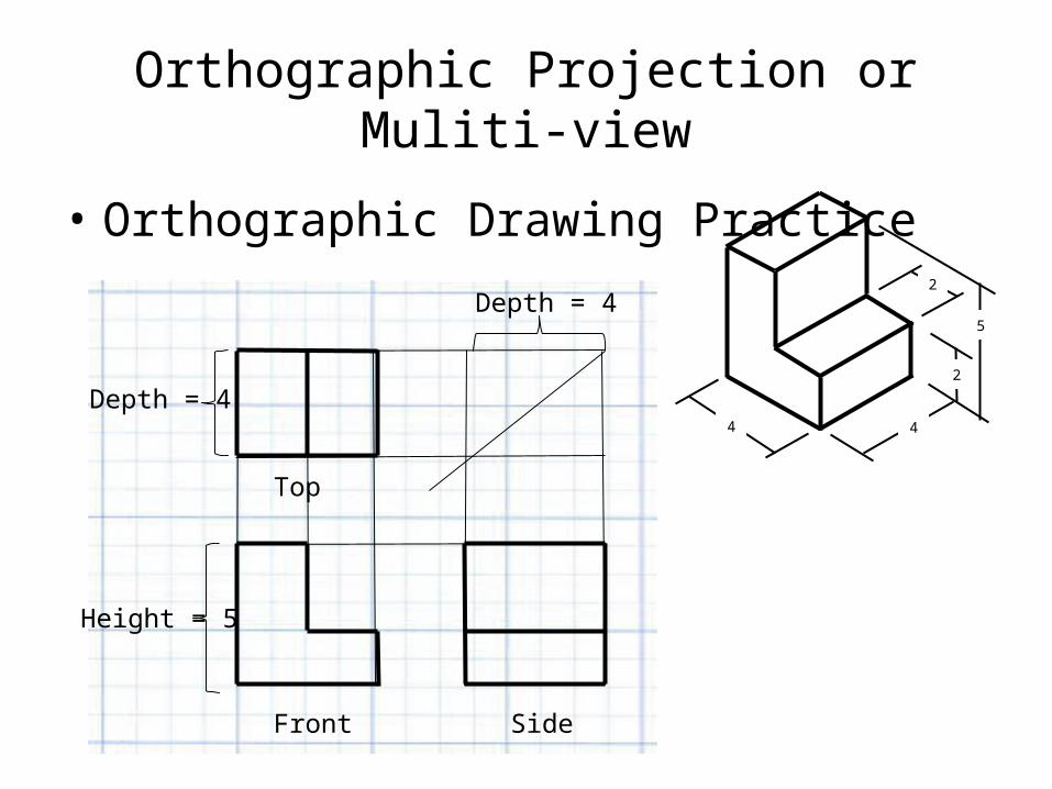
• Orthographic Drawing Practice2
2
5
44
Depth = 4
Height = 5
Side
Top
Front
Depth = 4
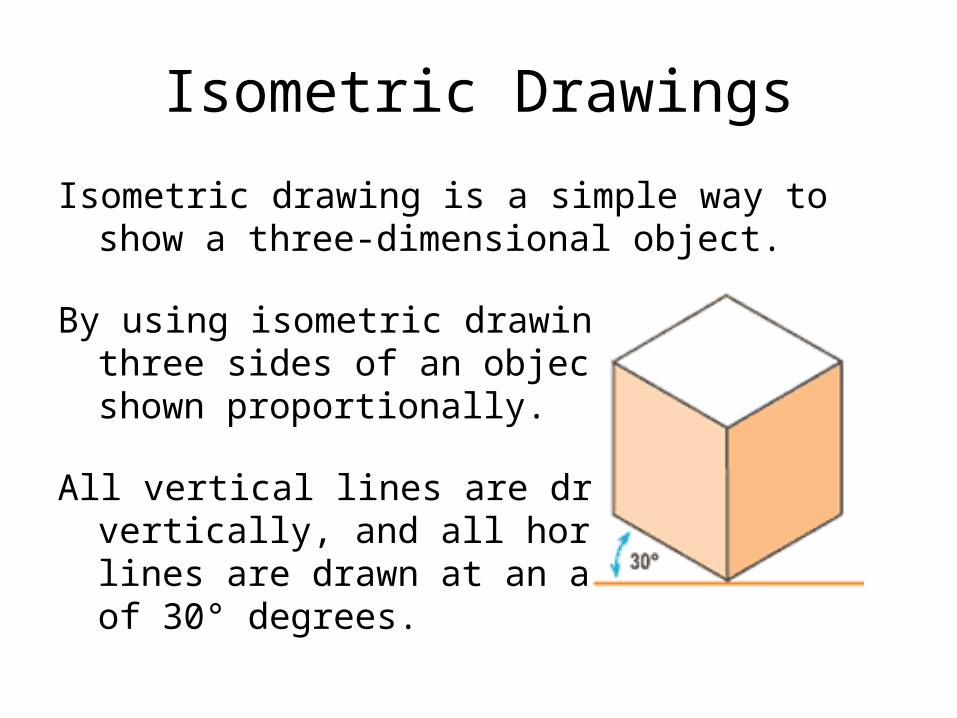
Isometric Drawings
Isometric drawing is a simple way to show a three-dimensional object.
By using isometric drawing , three sides of an object areshown proportionally.
All vertical lines are drawn vertically, and all horizontal lines are drawn at an angle of 30° degrees.
Isometric Drawings
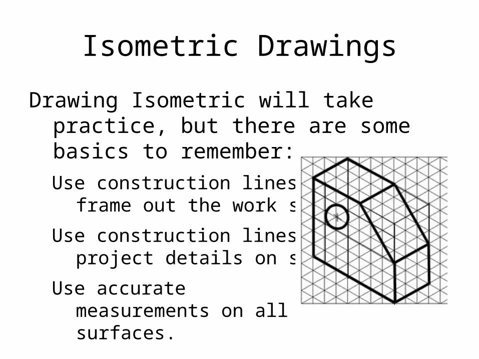
Drawing Isometric will take practice, but there are some basics to remember:
Use construction lines toframe out the work space.
Use construction lines to project details on surfaces.
Use accurate measurements on all surfaces.

Isometric Drawings
• Isometric Drawing Practice
Height = 5
Width= 4Depth= 4
2
2
5
44