Embed Size (px)
Citation preview

g GE
OPERATING MANUAL UNINTERRUPTIBLE POWER SUPPLY
LP 31 8 – 10 – 15 – 20 kVA
Series 1
g GE Digital Energy SA
6595 Riazzino (Locarno) Switzerland
Telephone: +41 (0) 91/850 51 51Fax: +41 (0) 91/850 51 44
LP Series UPS Technology for the digital world

g GE
OPM_LPS_31E_8K0_20K_1GB_V010.doc 2/40 Operating Manual LP 31 / 8-10-15-20 kVA
Model: LP 31 / 8 – 10 – 15 – 20 kVA / Series 1 Date of issue: 15.10.2003 File name: OPM_LPS_31E_8K0_20K_1GB_V010.doc Revision: 1.0 Author: Raimondo Bizzozero Identity No.:
Up-dating: Revision Concern Date
COPYRIGHT © 2003 by GE All rights reserved. The information contained in this publication is intended solely for the purposes indicated. The present publication and any other documentation supplied with the UPS system is not to be reproduced, either in part or in its entirety, without the prior written consent of GE. The illustrations and plans describing the equipment are intended as general reference only and are not necessarily complete in every detail. The content of this publication may be subject to modification without prior notice.
g GE
OPM_LPS_31E_8K0_20K_1GB_V010.doc 3/40 Operating Manual LP 31 / 8-10-15-20 kVA
Dear Customer, We thank you for selecting our products and are pleased to count you amongst our very valued customers at GE. We trust that the use of the LP 31 Uninterruptible Power Supply system, developed and produced to the highest standards of quality, will give you complete satisfaction. Please read carefully the Operating Manual which contains all the necessary information and describes all you need to know about the use of the UPS. Thank you for choosing GE !
Manufactured by: Distributed by: Your service contact:
g GE
GE Digital Energy SA 6595 Riazzino (Locarno) Switzerland

g GE
OPM_LPS_31E_8K0_20K_1GB_V010.doc 4/40 Operating Manual LP 31 / 8-10-15-20 kVA
Table of contents 1. INTRODUCTION & SAFETY RULES.................................................................................... 6
1.1 INTRODUCTION................................................................................................................. 6 1.2 SAFETY RULES.................................................................................................................. 6
1.2.1 General......................................................................................................................... 6 1.2.2 Installation .................................................................................................................... 6 1.2.3 Storage......................................................................................................................... 7 1.2.4 Batteries ....................................................................................................................... 7
2. FUNCTIONAL EXPLANATION ............................................................................................. 8
2.1 THE PRINCIPLES OF OPERATION..................................................................................... 8 2.2 NORMAL CONDITIONS..................................................................................................... 8 2.3 MAINS FAILURE ................................................................................................................ 9 2.4 AUTONOMY TIME ............................................................................................................. 9 2.5 AUTOMATIC BYPASS SWITCH ...................................................................................... 10 2.6 MANUAL BYPASS SWITCH ............................................................................................ 11
3. INSTALLATION.................................................................................................................... 12
3.1 PACKAGE CONTENTS...................................................................................................... 12 3.2 LOCATION........................................................................................................................ 12 3.3 INSTALLATION ................................................................................................................ 12
4. OPERATION ......................................................................................................................... 15
4.1 DESCRIPTION OF FRONT AND REAR PANEL ................................................................ 15 4.2 START-UP ........................................................................................................................ 17 4.3 USE................................................................................................................................... 18
4.3.1 Information screens .................................................................................................... 19 4.3.2 Status Messages and Alarm Messages ...................................................................... 20 4.3.3 Service screens .......................................................................................................... 24 4.3.4 Setup menu ................................................................................................................ 26
4.4 TEST SCREENS................................................................................................................ 28 4.4.1 Battery Test, general .................................................................................................. 28 4.4.2 Quick Battery Test ...................................................................................................... 28 4.4.3 Deep Battery Test....................................................................................................... 29
4.5 OTHER FEATURES........................................................................................................... 31 4.5.1 ECO-mode.................................................................................................................. 31 4.5.2 Shutdown.................................................................................................................... 31 4.5.3 Mains start .................................................................................................................. 31 4.5.4 Sleep and wake-up ..................................................................................................... 32 4.5.5 Overload protection in bypass mode........................................................................... 32

g GE
OPM_LPS_31E_8K0_20K_1GB_V010.doc 5/40 Operating Manual LP 31 / 8-10-15-20 kVA
5. INTERFACE FEATURES ...................................................................................................... 33
5.1 COMCONNECT (RS232) INTERFACE .............................................................................. 33 5.2 POTENTIAL FREE CONTACT INTERFACE ...................................................................... 34 5.3 SNMP INTERFACE (OPTIONAL)...................................................................................... 34
6. OPTIONS .............................................................................................................................. 35
6.1 EXTENDED RUN-TIME VERSIONS ................................................................................. 35 6.2 SNMP INTERFACE CARD ................................................................................................ 35
7. MAINTENANCE ................................................................................................................... 36
7.1 GENERAL ......................................................................................................................... 36 7.2 COOLING FAN.................................................................................................................. 36 7.3 BATTERIES....................................................................................................................... 36 7.4 SAFETY............................................................................................................................. 37 7.5 STORAGE......................................................................................................................... 37
8. TROUBLESHOOTING.......................................................................................................... 38
9. ANNEX ................................................................................................................................. 40
9.1 TECHNICAL DATA SHEETS............................................................................................. 40 9.2 TECHNICAL DIAGRAMS.................................................................................................. 40

g GE
OPM_LPS_31E_8K0_20K_1GB_V010.doc 6/40 Operating Manual LP 31 / 8-10-15-20 kVA
1. INTRODUCTION & SAFETY RULES 1.1 INTRODUCTION
More than ever before, today's advanced electronic equipment, with complex integrated circuits and other sensitive electronics, needs a stable and continuous AC power supply to operate correctly. While the power coming from the wall socket outlet is often unreliable, a LP 31 UPS provides the security of completely uninterrupted power. A compact, truly on-line system, the LP 31 UPS protects your equipment from all forms of power interference, including complete power failure. A simple and elegant circuit design, together with extensive protection against abnormal operating conditions (e.g. overload, short circuit, overheating), makes the LP 31 exceptionally reliable.
1.2 SAFETY RULES
1.2.1 General
This equipment can be operated by anyone, without any special training.
WARNING: RISK OF ELECTRICAL SHOCK
The UPS contains its own energy source: batteries. The output terminals may be electrically live, even when the UPS is disconnected from the mains. Dangerous voltages may be present during battery operation. The batteries must be disconnected during maintenance or service work. The UPS contains potentially hazardous voltages. Do not open the UPS, there are no user serviceable parts inside. All maintenance and service work should be performed by qualified service personnel.
1.2.2 Installation
The UPS is intended to be used in normal domestic and office situations. The UPS may only be installed by trained personnel. The UPS should only be powered from a three-phase, four-wire AC source equipped with a protective earth connection. Do not install the UPS in an excessively humid environment or near water. Avoid liquids or any foreign object to get into the UPS. The unit must be placed in a sufficiently ventilated area; the ambient temperature should not exceed 40°C. Optimal battery lifetime is obtained if the ambient temperature does not exceed 30°C. It is important that ventilation air can move freely around and through the unit. Do not block the air vents. Avoid locations in direct sunlight or near heat sources. Do not connect household appliances such as electric heaters, toasters or vacuum cleaners to the UPS.

g GE
OPM_LPS_31E_8K0_20K_1GB_V010.doc 7/40 Operating Manual LP 31 / 8-10-15-20 kVA
1.2.3 Storage
Store the UPS in a dry location, storage temperature must be within –20°C to +45°C. If the unit is stored for a period exceeding 3 months, the batteries must be recharged periodically. Connect the unit to the mains and switch it on for a period of approx. 48 hours, minimum every 3 months.
1.2.4 Batteries
• When replacing the batteries, use the same number and voltage (V) / capacity (Ah).
• Proper disposal or recycling of the batteries is required. Refer to your local codes for disposal requirements.
• Never dispose of batteries in a fire: they may explode.
• Do not open or mutilate batteries: their contents (electrolyte) may be extremely toxic.
If exposed to electrolyte, wash immediately with plenty of water.
• Avoid charging in a sealed container.
• Never short circuit batteries. When working with batteries, remove watches, rings or other metal objects, and only use insulated tools.

g GE
OPM_LPS_31E_8K0_20K_1GB_V010.doc 8/40 Operating Manual LP 31 / 8-10-15-20 kVA
2. FUNCTIONAL EXPLANATION
2.1 THE PRINCIPLES OF OPERATION
The LP 31 UPS stores electric energy in batteries housed in the unit. This allows the UPS to supply output power even when the incoming mains power is cut OFF completely. Energy is stored as Direct Current (DC), while input and output energy must be Alternating Current (AC). Therefore the UPS contains an input converter (AC to DC) and an output converter (DC to AC) (fig.1). The LP 31 UPS is a SECOND GENERATION On-line UPS with: • battery not in line with the DC link, resulting in: - enhanced battery life; - optimal battery charging; • full wave input converter with power factor correction; • extremely wide input voltage and input frequency tolerance; • output converter (inverter) using IGBT technology.
2.2 NORMAL CONDITIONS
Under normal conditions (see section 9 - Input Specifications), energy from the mains is channelled through the input converter, which supplies the output converter and, together with the battery charger, keeps the battery fully charged. The output converter synthesises a completely new AC output sine wave to supply the load (electrical equipment).
Figure 1 - Block diagram, mains present
(1) RFI = Radio Frequency Interference (2) PF = Power Factor

g GE
OPM_LPS_31E_8K0_20K_1GB_V010.doc 9/40 Operating Manual LP 31 / 8-10-15-20 kVA
2.3 MAINS FAILURE
In the event of a mains power failure (i.e. absent or outside tolerance) the system uses the energy reserve stored in the battery to continue to produce AC power, ensuring unbroken output (fig. 2). No interruption or alteration will ever be noticed in the output power. In the event of an extended mains failure, the output converter will stop when the battery energy has been used up. At this point, the UPS is no longer able to power the connected equipment. When the mains is re-established within tolerance, the output converter will be supplied again by the input converter and the batteries will be recharged, making them ready to support future power.
Figure 2 - Block diagram, mains failure
2.4 AUTONOMY TIME
The autonomy time, the time the output converter can operate on battery, depends on the capacity of the battery and on the power demand of the equipment supplied by the LP 31 UPS. Estimates of run-times are given.
LOAD LP 31 8 kVA
LP 31 10 kVA
LP 31 15 kVA
LP 31 20 kVA
25 % 75 minutes 51 minutes 80 minutes 56 minutes 50 % 35 minutes 24 minutes 30 minutes 24 minutes 100 % 14 minutes 10 minutes 13 minutes 10 minutes
Units connected to battery cabinets will have longer autonomy times. See section 6 - Options.

g GE
OPM_LPS_31E_8K0_20K_1GB_V010.doc 10/40 Operating Manual LP 31 / 8-10-15-20 kVA
2.5 AUTOMATIC BYPASS SWITCH
If the output converter is unable to deliver the demanded output power (overload, overtemperature) the bypass switch will automatically transfer the load to the mains. If bypass operation is caused by an overload situation, the UPS will only switch back to output converter if the load is reduced to less than 100%. If bypass operation is caused by overtemperature, the UPS will only switch back when the temperature has dropped below the alarm level. In case of a severe overload or short-circuit the magnetic bypass circuit breaker (front panel, see 4.1) may trip in order to protect the UPS. If the current is insufficiently high to trip the breaker, the UPS will be switched OFF by the software in order to protect the UPS and connected equipment. See also chapter 4.5 “overload protection in bypass mode” for more information. When the normal situation is restored, and the UPS was not switched OFF due to software protection or bypass breaker trip, the load will be transferred back to the output converter without any interruption. If a bypass power failure occurs during bypass operation, load power is lost. If the UPS functions under overload conditions it may not be able to protect the load.
Figure 3 - Bypass operation: automatic bypass
g GE
OPM_LPS_31E_8K0_20K_1GB_V010.doc 11/40 Operating Manual LP 31 / 8-10-15-20 kVA
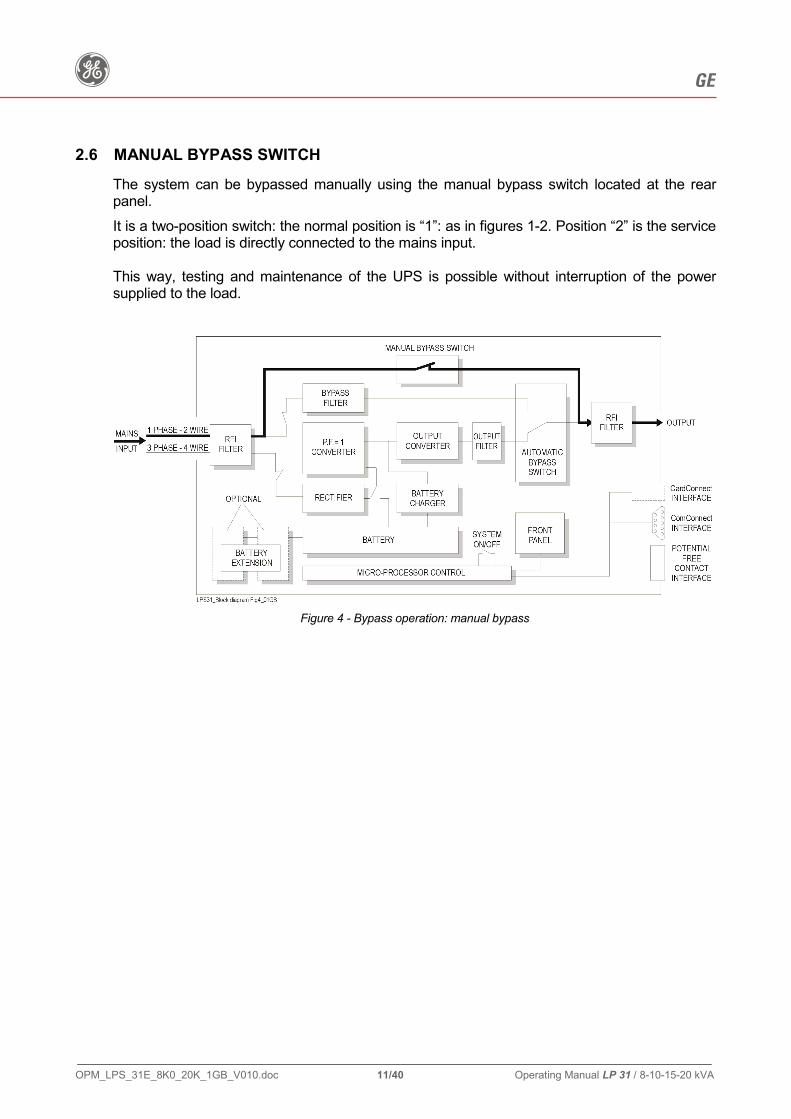
2.6 MANUAL BYPASS SWITCH
The system can be bypassed manually using the manual bypass switch located at the rear panel. It is a two-position switch: the normal position is “1”: as in figures 1-2. Position “2” is the service position: the load is directly connected to the mains input. This way, testing and maintenance of the UPS is possible without interruption of the power supplied to the load.
Figure 4 - Bypass operation: manual bypass

g GE
OPM_LPS_31E_8K0_20K_1GB_V010.doc 12/40 Operating Manual LP 31 / 8-10-15-20 kVA
3. INSTALLATION
3.1 PACKAGE CONTENTS
The shipping box contains a LP 31 UPS and this manual. Inspect the UPS for damage after unpacking. If any damage is present please immediately notify the carrier and the GE distributor. If a battery extension pack is to be connected to the UPS, a connection kit is required. This kit is delivered with each battery pack.
3.2 LOCATION
Please refer to chapter 1.2.2 - “Safety rules – installation“.
3.3 INSTALLATION
IMPORTANT: Before making any connection and switching on the LP 31 UPS, please check the following conditions: • the input voltage and frequency of your mains supply is 380/400/415 Volts and 50/(60)Hz;
standard delivery is 400V/50Hz, the input is 3-phase 4-wire, the neutral connection is essential;
• the UPS has to be protected by distribution fuses, slow blow, connected to the mains input of the UPS.
For fuse values please refer to drawing “SINGLE LINE DIAGRAM”;
• if an earth leakage circuit breaker is installed in the mains input circuit, be sure its rating is 1A (differential) or more.
Other circuit breakers may trip due to the return current of the load which partly passes through the bypass neutral;
• the total power requirements of the computer equipment to be protected does not exceed the rated output power of the UPS (see section 9 - Specifications).
Output power for your unit is indicated on the rating label on the rear panel of the unit.
The UPS may only be installed by trained personnel. The UPS must be grounded when in use: Connect the UPS to a three-phase, four-wire AC source equipped with an earth connection.
WARNING: This is a Class A product. In a domestic environment, this product may cause radio interference, in which case the user may be required to take additional measures.

g GE
OPM_LPS_31E_8K0_20K_1GB_V010.doc 13/40 Operating Manual LP 31 / 8-10-15-20 kVA
Installation procedure: 1. Please refer to figure 6 in chapter 4.1 and drawing “TERMINALS” for the location of terminals. 2. Remove the rear grid by loosening the 4 screws. 3. Remove the middle front panel that covers the MCB-switches. Hold the panel at both sides and pull firmly. 4. Remove the lower front panel that covers the battery drawers. Lift the panel and pull. 5. The input terminals are mounted at the rear side of the UPS. Connect the mains supply wires to the terminals 7 (L1), 8 (L2), 9 (L3) and 10 (Neutral) and the
earth wire to the EARTH terminal. 6. Connect the load wires to the terminals 1 (Line) and 2 (Neutral) and the earth wire to the EARTH
terminal (3). 7. Connect the bypass supply wires to the terminals 4 (L1) and 5(N) and the earth wire to the
EARTH terminal (6). 8. Use the clamps that came with the unit to attach the wires to the rear of the cabinet. Position the clamps in the slots (20, see fig. 6). 9. If you want to install battery extension packs proceed with step 10. If you are not using battery extension packs skip to step 19. 10. Please refer to drawing “BATT. PACK CONNECTION”. Battery extension pack(s) are shipped with all materials necessary to connect them to the UPS
(see chapter 3.1). The pack(s) can be connected to the terminals at the rear panel of the UPS. The internal DC wires are already connected to the rear terminals 12,14 (plus) and 13,15
(minus). 11. Be sure that all MCBs are in OFF position. 12. Be sure that the mains supply voltage and the bypass voltage are not present on the input
terminals. 13. Make sure that all battery fuses at the front of the cabinet are removed. 14. Use a voltmeter to check that there is no DC voltage between terminals 12 and 13 and between
terminals 14 and 15. 15. Make sure that all battery fuses of the battery cabinet are removed. 16. First install the left plus (red) and minus (black) wire of the battery cabinet to the left plus and
minus of the UPS (terminals 12 and 13). Then install the right plus (red) and minus (black) to the right plus and minus of the UPS (terminals 14 and 15).
17. Install all battery fuses at the front of the battery cabinet and in the front of the UPS.
g GE
OPM_LPS_31E_8K0_20K_1GB_V010.doc 14/40 Operating Manual LP 31 / 8-10-15-20 kVA
18. In order to calculate the available back-up time related to the actual load, information on the capacity of the battery set is stored in the UPS. As the total battery capacity changes when battery extension packs are installed, the battery capacity must be re-programmed.
Please contact your dealer. 19. An emergency shutdown device can be connected to connector 18 on the interface PCB, pin 14
and pin 15. Off factory the pins 14-15 are interconnected. For more information see chapter 4.3.
20. For advanced communication possibilities, the ComConnect interface port (9-pin connector at
the rear of the unit) can be connected to a computer system (RS232 protocol). Furthermore four potential free contacts are available.
21. A plug-in UPS network interface card (optional) makes the UPS “SNMP manageable”.
This option can be used to connect the UPS directly to a computer network. See chapter 5 for more information.
22. If you have not installed a battery pack install all battery fuses at the front. Start at the upper
side. The number of fuses shipped with the UPS depends on the rating of the UPS: LP 31 / 8 - 10 kVA = 4 fuses LP 31 / 15 - 20 kVA = 8 fuses 23. Reinstall the rear panel and the lower front panel. 24. Connect the mains power to the UPS. 25. Turn all MCBs (ON/OFF, mains, bypass) into “ON” position (the sequence is not important).
Note: the UPS can be started on battery power when the mains input voltage is not available: just switch the UPS on with the ON/OFF switch.
To prevent accidental discharging of the batteries, it is recommended to start the unit only when the mains input voltage is available.
26. Reinstall the middle front panel.

g GE
OPM_LPS_31E_8K0_20K_1GB_V010.doc 15/40 Operating Manual LP 31 / 8-10-15-20 kVA
4. OPERATION
4.1 DESCRIPTION OF FRONT AND REAR PANEL
Figure 5 - Front panel
1 LCD screen 2x16 characters, shows UPS system data, status messages, settings.
2 - 4 Push-buttons
With the button keypads “-” (2) and “+” (4) you can scroll through the several screens, with keypad “reset/enter” (3) a selection is confirmed. Keypad activity is accompanied by a short beep. If there is no keypad activity during 20 seconds the LCD screen will return to the default screen (except for the service screens, see chapter 4.3.3).
5 LED “operation”
Normal operation. 6 LED “alarm”
Indicates an alarm situation, accompanied by alarm message(s) on the display and a sounding buzzer. See chapter 4.3.2 for more information
7 Inverter ON/OFF switch
Turn ON/OFF the inverter. ATTENTION! This switch does not switch OFF the bypass. When (7) is switched into OFF position, the bypass voltage will be supplied to the load.
8 Line fuse (MCB)
Protection fuse for mains input and battery charger.
9 Bypass fuse (MCB)
Protection fuse in case of overload or short circuit in the UPS load.

g GE
OPM_LPS_31E_8K0_20K_1GB_V010.doc 16/40 Operating Manual LP 31 / 8-10-15-20 kVA
Figure 6 – Rear panel 10 Manual Bypass Switch: 1 = load on UPS 2 = load on bypass 11 Input terminals: 7 (L1) / 8 (L2) / 9 (L3) 10 = neutral 11 = protective earth 12 Output terminals: 1 (L) / 2 (N), 3 = protective earth 13 Bypass input terminals: 4 (L) / 5 (N) 6 = protective earth 14 ComConnect Interface Port (RS232 - see chapter 5.1) 15 Interface PCB, with: 16 Alarm connector of the optional battery extension MCB. 17 Potential free contacts (see chapter 5.2), pin 1 = common, pin 2 = NC (not connected). 18 Emergency shutdown (EPO – Emergency Power Off). 19 Slot for optional SNMP plug-in card (behind PCB) (see chapter 5.3). 20 Slots to fasten cable clamps. 21 Battery extension connection terminals: 12, 14 (plus), 13, 15 (minus) e 16 (GND)

g GE
OPM_LPS_31E_8K0_20K_1GB_V010.doc 17/40 Operating Manual LP 31 / 8-10-15-20 kVA
4.2 START-UP 1. Switch on the UPS with switch “inverter ON/OFF” (7), MCB “mains ON/OFF” (8) and
MCB “bypass ON/OFF” (9). If battery extension packs are part of the system, turn the DC-MCBs on the UPS as well as on the extension pack(s) into “ON” position. The green LED “operation” will illuminate.
The UPS is capable of handling the high inrush currents of the (starting) load.
This means that all equipment protected by the UPS can be switched on by simply switching on the UPS. The simultaneously occurring inrush currents of the loads do not immediately cause bypass operation.
After switch-on the UPS will perform a self-test and the display will show: SELFTEST IN PROGRESS
After completion of the self-test the output voltage of the UPS is available. The display will show the default screen: model and actual load (values are examples).
LP 15-31 load 37%
In case of a system failure the self-test results in a failure message; this message is displayed for 30 seconds before the self-test is repeated automatically. If the faulty situation persists, switch OFF the UPS and contact your dealer.
2. Though the batteries (the internal energy reserve) were fully charged when the UPS
left the factory, they might have lost some energy during transportation and storage. It is recommended to allow the UPS to recharge the batteries during a few hours period: provided that mains power is present, leave the UPS switched on and:
- either do not connect computer equipment yet; - or connect the computer equipment to the bypass supply for a few hours by turning
the manual bypass switch (10) into position “2”.
This way you ensure that the UPS can provide sufficient autonomy time in case of a mains power failure (see chapters 2.3 and 2.4).
3. If not yet switched on, the equipment connected to the LP 31 UPS can be switched on
now; operate as usual.

g GE
OPM_LPS_31E_8K0_20K_1GB_V010.doc 18/40 Operating Manual LP 31 / 8-10-15-20 kVA
4.3 USE
Once the unit is in operation, there is no need to switch the unit ON/OFF during use. If an emergency shutdown switch has been installed (see chapter 3.3) the UPS will stop immediately when the switch is opened. Restart is only possible after closing the switch and turning the UPS OFF and on again with switch “inverter ON/OFF” (7) on the front panel. The UPS is operated via the push buttons and the LCD display on the front panel. Furthermore the UPS can be controlled via the ComConnect interface port. For more information see chapter 4.5 and section 5 – “Interface features”. The menus on the display can be divided into 4 groups: 1 standard menu; 2 information menu (see chapter 4.3.1); 3 status- en alarm menu (see chapter 4.3.2); 4 service menu (see chapter 4.3.3). The standard menu shows UPS model and actual load.
LP 15-31 load 37%
g GE
OPM_LPS_31E_8K0_20K_1GB_V010.doc 19/40 Operating Manual LP 31 / 8-10-15-20 kVA
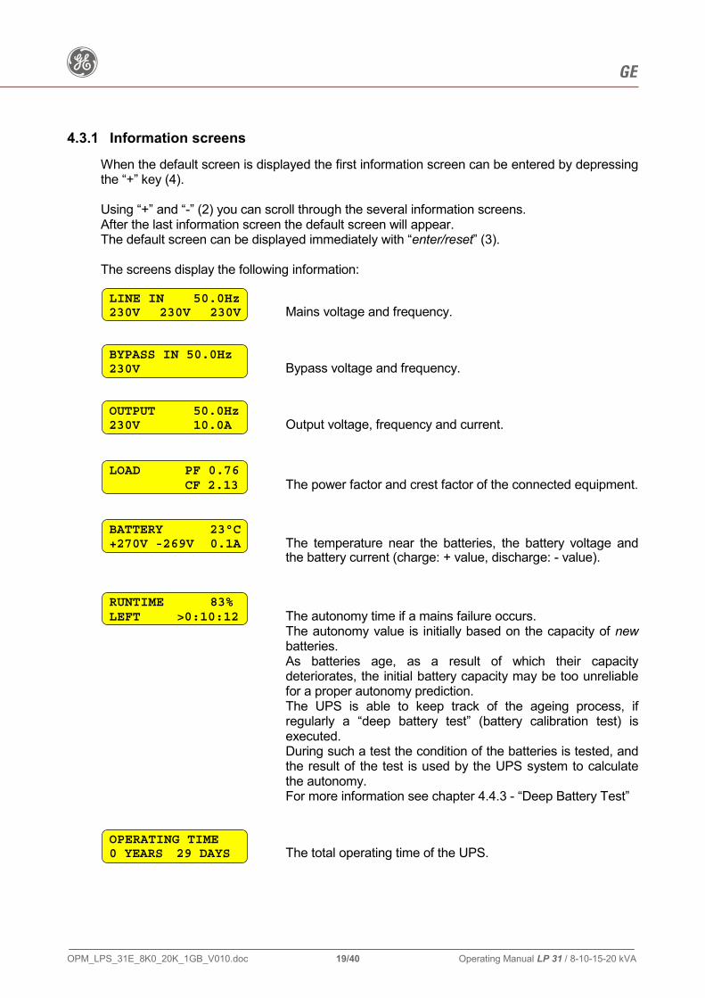
4.3.1 Information screens
When the default screen is displayed the first information screen can be entered by depressing the “+” key (4). Using “+” and “-” (2) you can scroll through the several information screens. After the last information screen the default screen will appear. The default screen can be displayed immediately with “enter/reset” (3). The screens display the following information: LINE IN 50.0Hz 230V 230V 230V Mains voltage and frequency.
BYPASS IN 50.0Hz 230V Bypass voltage and frequency.
OUTPUT 50.0Hz 230V 10.0A Output voltage, frequency and current.
LOAD PF 0.76 CF 2.13 The power factor and crest factor of the connected equipment.
BATTERY 23°C +270V -269V 0.1A The temperature near the batteries, the battery voltage and
the battery current (charge: + value, discharge: - value). RUNTIME 83% LEFT >0:10:12 The autonomy time if a mains failure occurs.
The autonomy value is initially based on the capacity of new batteries. As batteries age, as a result of which their capacity deteriorates, the initial battery capacity may be too unreliable for a proper autonomy prediction. The UPS is able to keep track of the ageing process, if regularly a “deep battery test” (battery calibration test) is executed. During such a test the condition of the batteries is tested, and the result of the test is used by the UPS system to calculate the autonomy. For more information see chapter 4.4.3 - “Deep Battery Test”
OPERATING TIME 0 YEARS 29 DAYS The total operating time of the UPS.

g GE
OPM_LPS_31E_8K0_20K_1GB_V010.doc 20/40 Operating Manual LP 31 / 8-10-15-20 kVA
4.3.2 Status Messages and Alarm Messages
The LP 31 UPS alerts the user with a standard alarm screen that the operating mode has changed and/or that an alarm situation occurs: ON LINE ALARM (press up) The actual operating mode, the possible modes are
mentioned below. The lower line -if displayed- shows that an alarm occurred.
More information can be retrieved with the “+” key. If no further information is available, the second line is blank.
Possible operating modes: ON LINE The normal operating mode. For more information see chapter 2.2. ON BYPASS Overload or failure situation. For more information see chapter 2.5. ON BATTERY For a detailed description of this mode see chapter 2.3. OUTPUT OFF No power is delivered to the load.
This can be the result of a command via the ComConnect Port, or because no electric energy is available (mains failure, empty batteries).
ON MANUAL BYPASS Service mode. For more information see chapter 2.6.
From the standard alarm screen depressing “+” shows which alarms are active, in priority order. Scroll through the screens with “+” and “-”. Alarm message texts can succeed each other. The following messages are possible LOADnotPROTECTED CAP. C1 DEFECT The output capacitor C1 is defective. Contact your dealer. UPS OVERLOADED REDUCE LOAD The load exceeds the rated output power of the UPS, and the
output voltage can no longer be guaranteed. This text alternates with the following screen:
UPS OVERLOADED Load 107% Showing the actual load as % of the nominal UPS rating.
These messages are displayed if the load is > 100%. If the load exceeds 150% the UPS will immediately switch to bypass, assuming that the conditions for a transfer to bypass are fulfilled. If an overload condition between 100-150% persists, the UPS can eventually also switch to bypass operation due to temperature protection. If a transfer to bypass is inhibited (due to voltage or frequency errors of the mains supply) the UPS may automatically switch OFF within a few seconds (load dependent). Output power is lost at that moment. To avoid these problems, be absolutely certain that the power demands of the protected equipment are within the limits of the UPS.

g GE
OPM_LPS_31E_8K0_20K_1GB_V010.doc 21/40 Operating Manual LP 31 / 8-10-15-20 kVA
LOADnotPROTECTED TEMP TOO HIGH The temperature of the cooling plates or output transformer is
too high. As a result the load may be transferred to bypass. The operating temperature can rise intolerable as a result of: • extreme environmental temperature; • lack of proper ventilation; • an overload situation; • fan failure. If the UPS operates in “on line” mode, it will switch to bypass mode (if allowed, see explanation in alarm “UPS overloaded” above) until the temperature is normal again. If however the UPS operates “on battery”, a shutdown will occur and output power is lost. LOADnotPROTECTED The DC inter-circuit voltage is too high, internal failure VOLTAGE TOO HIGH
BATTERY CHARGER VOLTAGE TOO HIGH The output voltage of the battery charger is too high, internal
failure. BATTERY CHARGER TEMP TOO HIGH The battery temperature is too high due to a battery failure or
a too high ambient temperature. BATTERY CHARGER NO FLOAT After 24 hours of charging time, the battery voltage did not
reach the normal float voltage. This may be caused by faulty batteries, many battery packs
connected or a charger fault. CAPACITOR C2 CAPACITY LOW One or more of the DC-capacitors needs replacement due to
ageing or failure.
CAPACITOR C3 CAPACITY LOW One or more of the DC-capacitors needs replacement due to
ageing or failure.
LOADnotPROTECTED INVERTER OFF Due to a failure the output converter's output is not available. As a result the load may have been transferred to bypass.
LOADnotPROTECTED BATTERY DEPLETED The remaining autonomy is zero. As a result the load may have been transferred to bypass.

g GE
OPM_LPS_31E_8K0_20K_1GB_V010.doc 22/40 Operating Manual LP 31 / 8-10-15-20 kVA
LOADnotPROTECTED BATTERY LOW The remaining autonomy is less than the set time (standard 2
minutes). This text alternates with the following screen:
UPS SHUTDOWN LEFT 2 MINUTES The output voltage can be lost after the indicated time due to
discharged battery. Controlled shutdown of any computer equipment is absolutely necessary at this point. (Using the ComConnect communications interface, this procedure can be initiated automatically on unattended systems). If the UPS operates at 100% load, the shut-down procedure should be completed within 2 minutes after the “battery low” alarm started.
When the batteries are fully discharged, the UPS is no longer able to power the connected equipment.
INTERNAL BATTERY FUSE FAILURE One of the internal battery fuses is defective; this may have
been caused by an internal system failure. This alarm also appears if no batteries are installed.
EXTERNAL BATTERY FUSE FAILURE The battery extension MCB is in “OFF” position (down):
energy reserve of the battery extension pack is not available. If not manually operated, this may have been caused by faulty
wiring or battery failure.
REPLACE BATTERY The batteries are (almost) chemically worn out. If the batteries are aged, they must be replaced as soon as
possible to ensure full protection for your equipment (see chapter 7.3).
INPUT out LIMITS 137V 138V 140V The mains voltage or mains frequency are outside UPS input
tolerance (see section 9 - Specifications). BYPASS out LIMITS 170V 52.7Hz The mains voltage or mains frequency are outside bypass
input tolerance but inside UPS (rectifier) input tolerance (see section 9 - Specifications).
Bypass operation is inhibited: if for whatever reason the output converter is not able to deliver the required output, output power is lost

g GE
OPM_LPS_31E_8K0_20K_1GB_V010.doc 23/40 Operating Manual LP 31 / 8-10-15-20 kVA
INPUT AND OUTPUT NOT SYNCRONIZED The output frequency is not synchronised to the mains (input)
frequency. The automatic bypass switch is not able to transfer the load from output converter to bypass and reverse (see chapter 2.5). This requires synchronisation of the output frequency with the mains supply frequency. Synchronisation is only possible if the mains frequency remains within certain limits (see section 9 - Specifications). If output converter and mains are not synchronised bypass operation is inhibited. If for whatever reason the output converter is not able to deliver the required output, output power is lost.
RUNTIME LEFT 0:09:41 The remaining autonomy time.
This figure is counted down during battery operation until either the mains returns or the batteries are empty.
OUTPUT OFF NO INPUT POWER The output is switched OFF due to a faulty situation, indicated
by the second line, e.g. no input power and depleted batteries. PROG. SHUTDOWN WITHIN 0:09:17 The output will be switched OFF via ComConnect. The second line indicates the time until shutdown.
PROG. SHUTDOWN LEFT 0:14:03 The output is switched OFF via ComConnect. The second line indicates the time until wake-up.
IMMEDIATE SHUTDOWN The wire on connector 18 (rear panel, see figure 6) is
interrupted. The output is no longer available. To restart the unit, restore the connection and turn ON/OFF
switch (7) OFF and ON again.

g GE
OPM_LPS_31E_8K0_20K_1GB_V010.doc 24/40 Operating Manual LP 31 / 8-10-15-20 kVA
4.3.3 Service screens
When the default screen is displayed you can enter the first service screen by depressing the keys “-” (2) and “enter/reset” (3) simultaneously during approx. 1 second. Using “+” and “-” (2) you can scroll through the several service screens. SERVICE SCREENS ENTER/RESET exit The intro service screen. ”Enter/reset” returns to the default screen.
SERIAL NUMBER D154/02 9731A001 The serial number of the UPS.
SOFTWARE VERSION R1.x Release number of the installed software.
ECO ENABLED ENTER/RESET CHNG ECO-Mode feature (see paragraphe 4.5.1):
ENABLED = is enabled DISABLED = is disabled FAN SPEED 10 INV.DC: +380-380 Service information about fan speed (min. 10, max. 30) and
internal DC voltage. HEATSI.TEMP: 567 BATT.TEMP: 23ºC Service information on internal temperature levels, values in
mV over the temperature sensors. FLOAT CHARGE: 1 OUTPUT FAST: 0 Upper line: “1” = batteries have reached float voltage. Second line: service information on output converter.
INVERTER: 1 Q4: 1 Service information on internal UPS components.
FREQ RANGE: 2% NO LOAD: 1 Frequency tracking range: output converter frequency will follow the bypass frequency within these limits before returning to its own internal frequency. Standard setting: nominal ±2%. Can be changed into nominal ±4% or ±6%. Contact your dealer. No-load shutdown: after a 10 minutes delay the UPS will shut down during mains failure if the load is < 2%. It will restart after the mains returns or when the unit is switched OFF and ON again. Default setting = 1 (active).

g GE
OPM_LPS_31E_8K0_20K_1GB_V010.doc 25/40 Operating Manual LP 31 / 8-10-15-20 kVA
QUICK BATTERY TEST PRESS ENTER Start of the manual Quick Battery Test.
See for more information chapter 4.4.2 “Quick Battery Test”. CALIBRATE BAT Press DOWN+ENTER Start of the manual Deep Battery Calibration Test.
See for more information chapter 4.4.3 “Deep Battery Calibration Test”.
IC: I1h1 + 5.7A -5.9A Service information on internal UPS components.
BYPASS OK BYPASS off Service information on internal UPS components.
LAST TEST TIME 10:17:15 14.0Ah Duration of latest test performed, hh/mm/ss,
(hours/minutes/seconds). FORCE BYPASS press DOWN+ENTER The UPS transfers the load to bypass when the keys “-” (2)
and “enter/reset” (3) on the front panel are depressed simultaneously during approx. 2 seconds.
If the bypass supply is not within limits, the lower line will show the text “UNAVAILABLE”.
AUTOMATIC BYPASS ENABLED Service set up information whether the bypass is enabled
(default) or disabled. If disabled: UPS will NOT go to bypass. BATTERY 14Ah BAT. CHARGE 99% Service set up information about the total battery capacity.
Information about the actual battery charge condition. PLL LOCK SPEED NORMAL Service set up information about frequency tracking speed for
the inverter to follow the bypass frequency, NORMAL (1Hz/sec.) is the normal value and default.
HIGH (5Hz/sec.) may be suitable if the UPS is connected to a generator with fast frequency changes and the UPS must be synchronised to prevent alarms.

g GE
OPM_LPS_31E_8K0_20K_1GB_V010.doc 26/40 Operating Manual LP 31 / 8-10-15-20 kVA
4.3.4 Setup menu
To enter the setup menu: 1- Be sure the UPS is switched OFF.
2- Press push-button “enter/reset“ (front panel) and simultaneously turn switch “UPS ON/OFF“ (front panel) into position “ON“ (up).
Using push-buttons “+” and “-” you can scroll through the several setup screens, “enter/reset“ confirms a screen choice.
After selecting a setup screen you can scroll through its settings using the push-buttons “+” and “-”, a setting is confirmed by pressing “enter/reset“.
To abort the setup procedure (i.e. without changing the setting) just wait the 20 seconds time-out period after which the default screen will return. SETUP SCREENS ENTER/RESET exit The intro setup screen.
“enter/reset” return to the default screen. You can also wait 20 seconds: the time-out period of no key activity. Pressing “+” display the screens in the following order:
WARNING: OUTPUT CHANGE ON LINE A short reminder that the new settings will be valid
immediately after pressing the “enter/reset” key. LANGUAGE ENGLISH Changes the language of the screen messages:
you can select: English, German, French, Italian and Spanish.
OUTPUT FREQUENCY 50.0Hz The system output frequency. Range: 50/60 Hz.
CAUTION ! Changing of the output frequency can cause severe damage of equipment connected to the UPS:
Be sure that the new frequency is suitable for the connected equipment.
FREQUENCY RANGE 2% The frequency tracking range (in which the output converter
frequency will follow the bypass frequency). Range: 2/4/6 %.
If the bypass frequency is beyond the setting, the output converter will return to the fixed crystal controlled frequency.
PLL LOCK SPEED NORMAL The frequency tracking speed range (in which the output
converter frequency will follow the bypass frequency). Range: NORMAL (1Hz/sec), HIGH (5Hz/sec).

g GE
OPM_LPS_31E_8K0_20K_1GB_V010.doc 27/40 Operating Manual LP 31 / 8-10-15-20 kVA
OUTPUT VOLTAGE 230V The system output voltage. Range: 220/230/240 VAC.
BATTERY CAPACITY 7Ah Battery capacity. Range: 7 through 590 Ah, in 1 Ah steps. WARNING ! If you proceed, the information about the
actual battery condition (as a result of a deep battery test) is lost.
For more info see chapter 4.4.2 – “Quick Battery Test”.
FAN CURVE SMALL The fan speed. Range: SMALL/LARGE.
Proper setting optimizes the cooling capacity of the fans installed. DO NOT READJUST! Incorrect setting may lead to reduced lifetime of the power semiconductors.
NO-LOAD SHUTDOWN YES Setting “YES” means that the function is activated: the UPS
switch OFF during a mains failure when the load is less than 2% of the maximum load.
Range: YES/NO. AUTOMATIC BYPASS ENABLED Controls functioning of the automatic bypass switch. Range: ENABLED/DISABLED.
If the UPS is used as a frequency converter you may change the setting to “DISABLED”. Bypass operation will then inhibited and all alarms related to “bypass out of limits” are suppressed.

g GE
OPM_LPS_31E_8K0_20K_1GB_V010.doc 28/40 Operating Manual LP 31 / 8-10-15-20 kVA
4.4 TEST SCREENS
These screens show the test procedure, either started from the service menu (front panel keys) or via the UPS monitoring software (ComConnect Port). The upper line indicates the kind of test, the second line its proceeding. Upper lines: GENERAL SYSTEM (Overall test of system). QUICK BATTERY (Quick battery test). CALIBRATE BAT (Deep discharge battery test). BYPASS (Bypass test). Lower lines: TEST START The test will start soon. TEST ACTIVATED The test is running. TEST SUCCESSFUL The test has been completed successfully. TEST FAILED The test has not been completed successfully.
4.4.1 Battery Test, general
Automatic test The LP 31 UPS conducts periodic automatic battery tests to ensure that the batteries and the wiring are healthy and able to support power failures.
The tests do not cause any interruption in the function of the unit and are conducted after every 500 operating hours.
Manual test A manual battery test can be activated: - either through an interface kit, via the ComConnect Interface Port
(please refer to the manual of your interface package), or - via the front panel: see below.
4.4.2 Quick Battery Test
From the standard menu first enter the service menu (press “-” and “enter/reset” simultaneously during 2 seconds). Subsequently press “-” until the following screen appears: QUICK BATTERY TEST PRESS ENTER Key enter/reset confirms the selection, and the screen
shows:

g GE
OPM_LPS_31E_8K0_20K_1GB_V010.doc 29/40 Operating Manual LP 31 / 8-10-15-20 kVA
QUICK BATTERY TEST START The test status (indicated by the second line) can be:
TEST ACTIVATED = testing.
TEST SUCCESSFUL = the test has been completed succesfully.
TEST FAILED = the test could not be executed properly: not all test conditions were fulfilled.
NOT AVAILABLE = battery capacity too low to start the test. If the batteries are dangerously close to being worn out, a low priority alarm “REPLACE BATTERY” will be generated. The batteries must be replaced as soon as possible (see chapter 7.3). NOTE: if the manual test is started immediately after installation or after a power failure, the
UPS may generate a false “replace battery” alarm as the batteries have been (partly) discharged during transport/storage or during the power failure.
4.4.3 Deep Battery Test The calculation of the autonomy shown by the LCD, is based on the actual load and (initially) on the condition - and thus capacity - of new batteries. Due to ageing of the batteries this capacity will deteriorate, and gradually there will grow a difference between the calculated autonomy (shown in the screen) and the real autonomy. During a deep battery test the UPS will check and store the actual capacity of the batteries. This information will be used during future autonomy calculations. In order to ensure accurate autonomy prediction we advise to execute a deep battery test on a regular basis: every 6 months under normal operating conditions. If battery operation occurs more than once a week, the interval between the tests should be shorter. Software start: please refer to the manual of the appropriate monitoring software package for more information. Manual start: Test conditions: a deep battery test can be started via the front panel under the
following conditions: - the load should be more than 30% of the nominal load;
- the batteries should be fully charged, this means that they should not have been (partly) discharged during the last 24 hours;
- no alarm situation may exist.

g GE
OPM_LPS_31E_8K0_20K_1GB_V010.doc 30/40 Operating Manual LP 31 / 8-10-15-20 kVA
Procedure From the standard menu first enter the service menu (press “-” and “enter/reset” simultaneously during 2 seconds). Subsequently press “-” until the following screen appears: CALIBRATE BAT Press DOWN+ENTER Press “-” (2) + “enter/reset” (3) simultaneously, during at
least 1 second. The following screen appears:
CALIBRATE BAT TEST ACTIVATED The test is executed, this may take a few minutes with
standard battery and full load. Partial load and/or batt. extension packs can lengthen the test
period considerably. Do not change the load during the test, i.e. do not switch OFF
or ON connected equipment! The deep battery test discharges the batteries to “battery low” alarm level (see chapter 4.3.2 “battery low”). Please note that immediately after a deep battery test the expected autonomy time is very short: allow the UPS to recharge its batteries: allow the UPS to recharge its batteries. After the test the second line informs about the result: TEST SUCCESFUL = The test has been completed successfully. TEST FAILED = The test could not be executed properly: not all test conditions
were fulfilled. The UPS system was not informed about the actual battery
condition!

g GE
OPM_LPS_31E_8K0_20K_1GB_V010.doc 31/40 Operating Manual LP 31 / 8-10-15-20 kVA
4.5 OTHER FEATURES
4.5.1 ECO-mode
The UPS is equipped with the “ECO-Mode” feature. If the feature is enabled, the load is operated on mains through the electronic bypass switch. If the mains is interrupted or out of limits the load is automatically transferred to the inverter. Operating the load on mains improves the efficiency of the UPS with 5-8% and saves on energy cost. As the unit produces less heat in ECO-mode also the energy cost of an airco installation will be reduced. We advise not to use the ECO-mode in case of an unstable mains and critical load but only in case of a good mains supply combinet with a less critical load (e.g. lighting). After enabling the ECO-mode (please refer to service screens 4.3.3) the standard menu change to:
LP 15-31 load 37%% ECO
4.5.2 Shutdown
“Remote shutdown“: Using communication capabilities, the computer can direct the UPS to turn itself OFF following controlled shutdown of the system. Subsequently the UPS will remain OFF for at least a few seconds (see also 4.3). LED “operation” will blink green. The unit will start up again as soon as the mains returns. “No-load shutdown” The UPS will also switch OFF if the load is < 2% of the maximum load, and the input is absent for more than 10 minutes. For more information see chapter 4.3.2, message “SHUTDOWN ALARM”. “Emergency shutdown” (EPO – Emergency Power Off) Por more information see chapter 4.3.2, message “IMMEDIATE SHUTDOWN”.
4.5.3 Mains start
The UPS is able to start, even if the batteries are not connected. Alarm messages “BATTERY FUSE FAILURE” and “BATTERY DEPLETED” will be shown. The autonomy is zero.

g GE
OPM_LPS_31E_8K0_20K_1GB_V010.doc 32/40 Operating Manual LP 31 / 8-10-15-20 kVA
4.5.4 Sleep and wake-up
Probably your UPS monitoring software allows you to program a “sleep period” of the UPS by sending two commands to the UPS: - shutdown after # minutes and subsequently: - shutdown during # hours. After the first command the following screen appears: PROG. SHUTDOWN WITHIN 0:09:17 During the sleep period the output voltage is no longer
available. LED “operation” blinks green, and the LCD screen shows the time left until restart:
PROG. SHUTDOWN LEFT 0:14:03 If a mains failure occurs during the sleep period and the
battery voltage eventually drops below 200Vdc, the UPS will automatically switch OFF in order to save battery power.
When the mains returns the UPS will start up automatically. The programmed sleep time however is lost.
The sleep period can be cancelled by either turning the ON/OFF switch (7) OFF for a few seconds or by sending the appropriate command via the ComConnect port.
4.5.5 Overload protection in bypass mode
The LP 31 will protect itself in case of overload. Upon an overload, which is caused by abnormal circumstances, the UPS will switch to bypass operation, and subsequently the bypass input fuse on the front panel will trip. The capacity of the bypass fuse allows it to handle the inrush currents of the equipment connected to the UPS. The fuse will only trip after more than an hour at: LP 31 / 8 kVA: 45 A LP 31 / 10 kVA: 57 A LP 31 / 15 kVA: 90 A LP 31 / 20 kVA: 113 A In order to protect the UPS system the software will cut OFF the abnormal current: Typ 10 minutes 2 minutes LP 31 / 8 kVA: 41 A 52 A LP 31 / 10 kVA: 52 A 65 A LP 31 / 15 kVA: 83 A 104 A LP 31 / 20 kVA: 104 A 130 A Between 41-52A (LP 31 / 8 kVA), 52-65A (LP 31 / 10 kVA), 83-104A (LP 31 / 15 kVA), 104-130A (LP 31 / 20 kVA) the time is inversely proportional to the current.

g GE
OPM_LPS_31E_8K0_20K_1GB_V010.doc 33/40 Operating Manual LP 31 / 8-10-15-20 kVA
5. INTERFACE FEATURES
5.1 COMCONNECT (RS232) INTERFACE
Located at the back of the unit, the ComConnect is a plug-in interface port (9-pin, Sub-D, male) which enables advanced communication between the UPS and the computer (interface kit required). The microprocessor controlled and galvanically isolated ComConnect sends information concerning power levels and UPS condition to the computer or network interface. In the event that batteries are near exhaustion, it sends commands for unattended controlled shutdown of computer systems. The ComConnect can also receive UPS shutdown signals from computers or network interface. When signals are sent to the computer, a written message can appear on the screen to inform the user. Monitored conditions include:
• mains voltage availability;
• discharge level of batteries;
• temperature of the batteries;
• interactive control- and diagnostic information for stand-alone and network systems. Interface kits (cables and software) are available for most commonly used network operating systems, including Novell, UNIX, VMS, Banyan Vines, Windows Platforms, Apple, 3COM, IBM LANserver, IBM AS/400. Remote servicing through a modem (external) is possible with GE Service Software. We strongly recommend to use only original GE software products in combination with the ComConnect interface port. We only guarantee proper operation of original GE products. The ComConnect cable should be shielded, connect the cable shield to the computer cabinet only For specific information on GE's connectivity products please contact your dealer.
Figure 7 - ComConnect port
No. pin function: 1 RS232 input (UPS shutdown) 2 RS232 output 4 Windows’95 Plug&Play 5 Common

g GE
OPM_LPS_31E_8K0_20K_1GB_V010.doc 34/40 Operating Manual LP 31 / 8-10-15-20 kVA
5.2 POTENTIAL FREE CONTACT INTERFACE
Furthermore four potential free contacts are available for signalling to a user-defined system: see fig. 6 connector 17 – Section 4.1.
Potential free contacts: functions and pin numbers
Function Normally open Coommon Normally closed Bypass active 3 4 5
Battery low 6 7 8
General alarm 9 10 11
Utility failure 12 13 14 Max: 48VDC 500mA Min.: 5VDC 100mA
5.3 SNMP INTERFACE (OPTIONAL)
The optional SNMP plug-in card allows the data interface to be connected directly to an Ethernet network (thin coax, twisted pair, AUI). For more information please refer to the user manual that comes with the interface card. See also chapter 6.2.
g GE
OPM_LPS_31E_8K0_20K_1GB_V010.doc 35/40 Operating Manual LP 31 / 8-10-15-20 kVA
6. OPTIONS
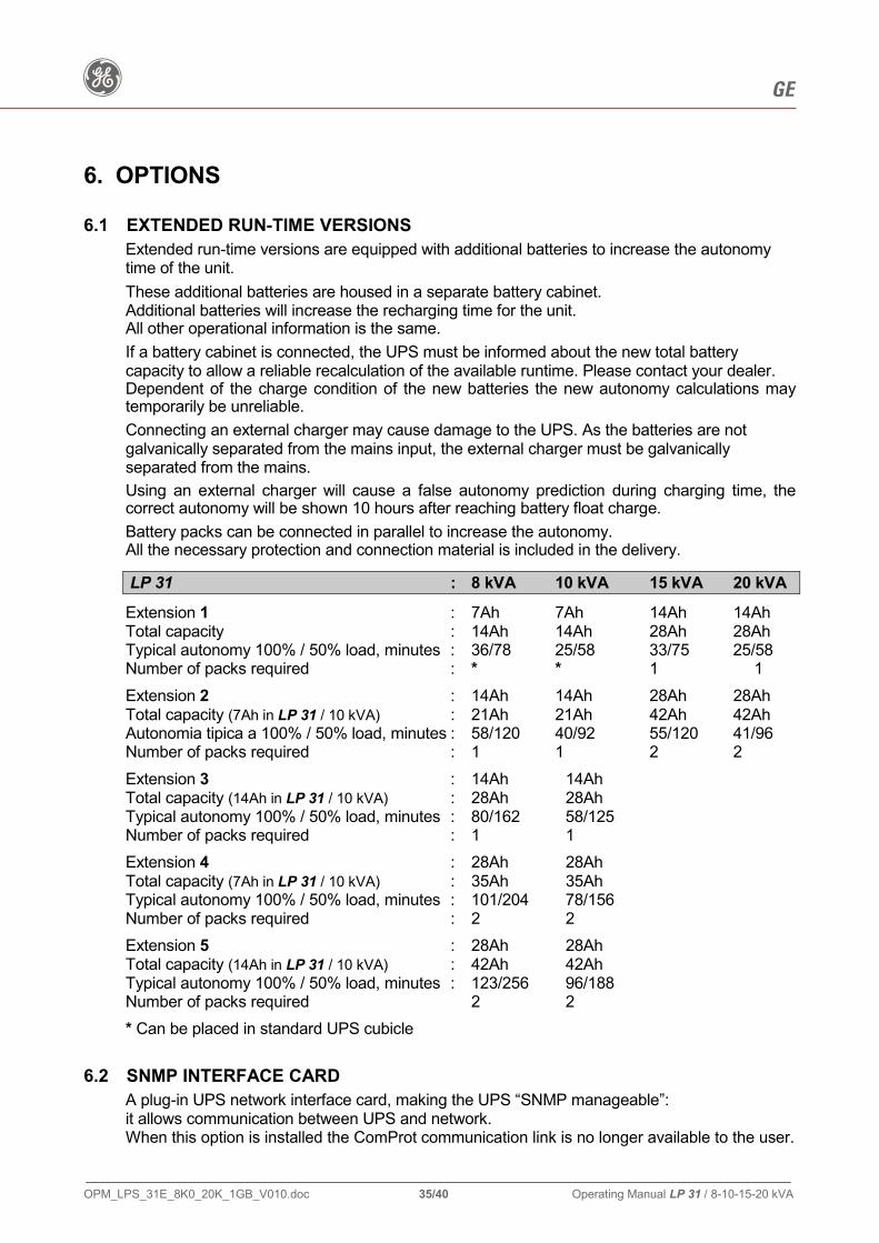
6.1 EXTENDED RUN-TIME VERSIONS Extended run-time versions are equipped with additional batteries to increase the autonomy time of the unit.
These additional batteries are housed in a separate battery cabinet. Additional batteries will increase the recharging time for the unit. All other operational information is the same.
If a battery cabinet is connected, the UPS must be informed about the new total battery capacity to allow a reliable recalculation of the available runtime. Please contact your dealer. Dependent of the charge condition of the new batteries the new autonomy calculations may temporarily be unreliable.
Connecting an external charger may cause damage to the UPS. As the batteries are not galvanically separated from the mains input, the external charger must be galvanically separated from the mains.
Using an external charger will cause a false autonomy prediction during charging time, the correct autonomy will be shown 10 hours after reaching battery float charge.
Battery packs can be connected in parallel to increase the autonomy. All the necessary protection and connection material is included in the delivery.
LP 31 : 8 kVA 10 kVA 15 kVA 20 kVA
Extension 1 : 7Ah 7Ah 14Ah 14Ah Total capacity : 14Ah 14Ah 28Ah 28Ah Typical autonomy 100% / 50% load, minutes : 36/78 25/58 33/75 25/58 Number of packs required : * * 1 1
Extension 2 : 14Ah 14Ah 28Ah 28Ah Total capacity (7Ah in LP 31 / 10 kVA) : 21Ah 21Ah 42Ah 42Ah Autonomia tipica a 100% / 50% load, minutes : 58/120 40/92 55/120 41/96 Number of packs required : 1 1 2 2
Extension 3 : 14Ah 14Ah Total capacity (14Ah in LP 31 / 10 kVA) : 28Ah 28Ah Typical autonomy 100% / 50% load, minutes : 80/162 58/125 Number of packs required : 1 1
Extension 4 : 28Ah 28Ah Total capacity (7Ah in LP 31 / 10 kVA) : 35Ah 35Ah Typical autonomy 100% / 50% load, minutes : 101/204 78/156 Number of packs required : 2 2
Extension 5 : 28Ah 28Ah Total capacity (14Ah in LP 31 / 10 kVA) : 42Ah 42Ah Typical autonomy 100% / 50% load, minutes : 123/256 96/188 Number of packs required 2 2
* Can be placed in standard UPS cubicle
6.2 SNMP INTERFACE CARD A plug-in UPS network interface card, making the UPS “SNMP manageable”: it allows communication between UPS and network. When this option is installed the ComProt communication link is no longer available to the user.

g GE
OPM_LPS_31E_8K0_20K_1GB_V010.doc 36/40 Operating Manual LP 31 / 8-10-15-20 kVA
7. MAINTENANCE
7.1 GENERAL
A UPS system, like other electrical equipment, needs periodic preventive maintenance. A regular maintenance check of your installation guarantees higher reliability of your safe power supply. Preventive maintenance work on the UPS can be done only by trained Service technicians.
We therefore recommend you sign a Maintenance and Service contract with the local Service Centre organisation.
7.2 COOLING FAN
The expected operational life of the cooling fans is approximately 20.000 to 40.000 hours of continuous operation. A high ambient temperature will shorten this operational life.
7.3 BATTERIES
The service life of the battery is from 3 to 6 years, depending on the operating temperature and on the number of discharge cycles. As a healthy battery is essential to the performance of the UPS, an automatic battery test is performed regularly to ensure failsafe operation (see chapter 4.4.1). When the condition of the battery is critical, the warning signal will be activated (buzzer 1x per 8 secs, and alarm message “Replace battery”, see chapter 4.3.2). The batteries must be replaced as soon as possible. Please contact your dealer. NOTE: under certain circumstances a manual battery test can result in a false alarm: please
see chapter 4.4.2 - “QUICK BATTERY TEST”. Regular deep battery tests are advised in order to re-calibrate the capacity of ageing batteries. See chapter 4.3.3 for more information. • Never short the battery terminals.Shorting may cause the battery to burn. • Avoid charging in a sealed container. • Proper disposal of batteries is required: refer to your local codes for disposal requirements. • Never dispose batteries in a fire: they may explode. • Never disassemble or reassemble batteries; their contents (electrolyte) may be extremely
toxic. If exposed to electrolyte, wash immediately with plenty of water, when acid contacts ones eyes wash them with a lot of water and see a doctor.

g GE
OPM_LPS_31E_8K0_20K_1GB_V010.doc 37/40 Operating Manual LP 31 / 8-10-15-20 kVA
7.4 SAFETY
WARNING!
When the LP 31 is operating, all parts of the electronics are directly connected to the mains and high voltages are present on all internal parts, including the battery. Even after disconnection from the mains, all parts inside the UPS, including the battery, conduct dangerous voltages (except the ComConnect output). For your safety, only authorised service personnel may remove the cabinet cover
7.5 STORAGE
Always store the UPS in a cool, dry location with the batteries in a fully charged state. Storing the unit for a period exceeding 3 months can reduce the life of the batteries. To maintain their normal life expectancy, the batteries must be recharged periodically. Connect the unit to a mains supply and switch on all MCBs at the front panel for a period of approximately 48 hours a minimum of every 3 months.

g GE
OPM_LPS_31E_8K0_20K_1GB_V010.doc 38/40 Operating Manual LP 31 / 8-10-15-20 kVA
8. TROUBLESHOOTING Whenever a malfunction occurs, first check external factors (e.g. connections, temperature, humidity or load) to determine whether the problem is caused by the unit itself or by its environment. Always check these external factors before concluding that your LP 31 UPS is faulty. The front screen will indicate the problem and solution (if the problem is due to environmental circumstances). If the solution is not shown on the screen, please contact your dealer. During the self-test, performed immediately after start-up, the UPS may detect a system failure. In this case (one of) the following messages can be displayed: SELFTEST FAILURE PCB POWER SUPPLY One or more voltages of the internal power supply is (are)
outside tolerance. Please contact your dealer.
SELFTEST FAILURE AC ON OUTPUT An external AC voltage (not the UPSs output voltage) was
detected on the output terminals. Please contact your dealer.
SELFTEST FAILURE PCB CONNECTORS One or more of the connectors inside the unit has a defect or
is not placed properly. Please contact your dealer.
SELFTEST FAILURE IC CHARGE A hardware error occurred during start-up of the input
converter. Please contact your dealer. SELFTEST FAILURE Comm. FAILURE Malfunction of the communication circuitry. Please contact your dealer.
SELFTEST FAILURE TEMP TOO HIGH The temperature of (one of) the components is (still) too high.
See chapter 4.3.2. SELFTEST FAILURE FATAL ERROR During start-up from mains, a hardware error occurred. Please contact your dealer.

g GE
OPM_LPS_31E_8K0_20K_1GB_V010.doc 39/40 Operating Manual LP 31 / 8-10-15-20 kVA
SELFTEST FAILURE IC STEP UP The step-up converter, which is a part of the input converter,
failed during start-up. Please contact your dealer. SELFTEST FAILURE EXT. BATTERY Checking the external batteries, the UPS detected a failure in
the hardware. SELFTEST FAILURE Uic TOO LOW Malfunction of input circuit: voltage delivered is too low.
The batteries may be faulty or depleted. Wait for a few hours, leave the UPS switched on. If absence of input power (mains failure, maintenance work) is expected to last longer than a few hours, switch OFF the UPS to save battery power.
If the UPS input power is absent for several days and the UPS remains on under no-load conditions, the batteries can be discharged very deeply, resulting in a short battery lifetime.
SELFTEST FAILURE Q4 NOT OK Hardware output voltage detection “Q4” is active. In case of a system failure the message is displayed for 30
seconds before the self test is repeated. If the faulty situation persists, please contact your dealer.

g GE
OPM_LPS_31E_8K0_20K_1GB_V010.doc 40/40 Operating Manual LP 31 / 8-10-15-20 kVA
9. ANNEX
9.1 TECHNICAL DATA SHEETS
Can be found included in the last section and are listings of the technical data of the UPS.
9.2 TECHNICAL DIAGRAMS
These are included in the last sections and include assembly layouts and functional drawings.
Drawing title: Drawing number: Single line diagram 400 023.8 page 1/4 Wiring diagram 400 023.8 page 2/4 Service diagram 400 023.8 page 3/4 Terminals on rear 400 023.8 page 4/4 UPS to battery cabinet connection 300 404 1 page 1/2 Installation of internal batteries pack 300 404 1 page 2/2 UPS general arrangement 400 033.7 page 1/5 UPS cubicle dimensions 400 033.7 page 2/5 Dismantlement of UPS cabinet 400 033.7 page 3/5 Battery cubicle dimensions 400 033.7 page 4/5 Dismantlement of battery cabinet 400 033.7 page 5/5