Embed Size (px)
Citation preview

* Read this instruction manual before the installation and use of BU100XR2/ BU200XR2 because it givesyou the critical do's and don'ts of the devices.
* Keep this instruction manual within easy reach where you will install BU100XR2/BU200XR2 so that youcan read it whenever necessary.No part or whole of this manual may be reproduced without permission.The contents of this manual are subject to change without notice.
BU100XR2 / BU200XR2Uninterruptible Power Supply (UPS)
Instruction Manual

IntroductionThank you for purchasing Omron's Uninterruptible Power Supply (UPS).
• The UPS protects computers and other devices from surge voltage (a phenomenon in which extraordinaryhigh voltage occurs instantaneously) caused by power failures, voltage variations, instantaneous voltagedrops and power failures, and thunders.
• Under usual service conditions, the UPS converts commercial power into a direct current, and reconvertedfrom the direct current to the 100-VAC output of stable sine wave.When detecting a failure of commercial power, the UPS switches itself to the uninterruptible power supplymode, and feed the output of a sine wave through devices linked to the UPS.The UPS is especially useful where power supply conditions are bad (for example, large voltage variations).
• Output capacities are 1KVA/700W for BU100XR2 and 2KVA/1.4KW for BU200XR2.
• The UPS provides the function of the Network Line Surge Protection to protect communications apparatussuch as modems from surge voltage that comes through the line (a phenomenon in which extraordinaryhigh voltage occurs instantaneously).
Notes on the use of the Backup UPS
• The UPS is designed and manufactured for OA equipment such as personal computers.Do not use the UPS with the devices that require very high reliability and safety as listed below.◊ Medical devices that may cause death directly◊ Particular applications of devices that may cause injury (applications that directly affect the operation
and control of planes, ships, railroads, elevators, and others)◊ Applications that are always subjected to vibration such as cars and ships◊ Applications in which a failure of the UPS may cause critical damage or effect on public safety (major
computer systems, main communications equipment, public transportation systems, and others)◊ Devices with the similar level of importance
• For the devices that adversely affect the safety of people and maintenance of utilities in the event offailure, special considerations related to operation, maintenance, and management of the system mustbe taken such as a standby system for emergency use and an auxiliary power generator.
• Observe the do's and don'ts of this instruction manual related to the operating and environmentalconditions.
• When you want to add the UPS to the critical system that requires very high reliability, contact us; ______.• Do not modify/alter your UPS.• The UPS is tailored to a domestic use only. Do not use the product abroad (outside Japan).◊ Voltages and frequencies may differ abroad and may cause a failure and/or fire.
© OMRON Corporation. 2002 All Right Reserved.

1
IMPORTANT SAFETY INSTRUCTION1. SAVE THESE INSTRUCTIONS.
This manual contains important instruction for Model BU100XR2/BU200XR2.
That should be followed during instruction of the UPS and batteries.
2. SYMBOL
This symbol indicates earth ground.
This symbol indicates turining on UPS.
This symbol indicates turining off UPS.
3. INTERNAL BATTERY.Internal battery voltage is 36Vdc for BU100XR2, 72Vdc for BU200XR2.
4. TEMPERATURE RATING.Maximum ambient temperature of UPS 40°C.
5. ENVIRONMENTThe unit is intended for installation in a temperature controlled, indoor area
free of conductive contaminants.

2
Table of Contents
Table of Contents
IntroductionIMPORTANT SAFETY INSTRUCTION .............................................................................................................. 1Directions for safe use ....................................................................................................................................... 31. Preparation .................................................................................................................................................... 9
1-1 Unpacking the UPS ............................................................................................................................. 91-2 Checking the accessories ................................................................................................................... 91-3 Exterior features ................................................................................................................................ 101-4 Explanetion of symbol used on unit ................................................................................................... 11
2. Installation and connection .......................................................................................................................... 122-1 Precautions and notes on installation and connection ...................................................................... 122-2 Installation ......................................................................................................................................... 142-3 Connecting and modifying AC input cable ......................................................................................... 162-4 Connecting a battery unit (BU200XR2) ............................................................................................. 172-5 Adding a battery unit (BU100XR2, BU200XR2) ................................................................................ 182-6 Adding the UPS output receptacle (BU200XR2) ............................................................................... 182-7 Connecting method of devices .......................................................................................................... 192-8 Checking the operation ..................................................................................................................... 212-9 Charging the battery .......................................................................................................................... 232-10 Measuring the backup time .............................................................................................................. 23
3. Operating the UPS ..................................................................................................................................... 243-1 Precautions and notes on operation .................................................................................................. 243-2 Start and stop procedures ................................................................................................................. 263-3 Beep and display ............................................................................................................................... 27
4. Functions of the UPS ................................................................................................................................. 304-1 Suspending a beep ........................................................................................................................... 304-2 Testing the UPS (executing the self-diagnostic test) ......................................................................... 304-3 Description of the auto battery tests .................................................................................................. 31
5. Measuring the backup time .......................................................................................................................... 325-1 Measuring method of the backup time .............................................................................................. 325-2 Estimated backup time ...................................................................................................................... 32
6. Maintenance and inspection ....................................................................................................................... 336-1 Checking the battery ......................................................................................................................... 336-2 Replacing the battery ........................................................................................................................ 336-3 Cleaning ............................................................................................................................................ 406-4 Cautions at the maintenance of devices connected to the UPS ....................................................... 40
7. Using the Network Link Surge Protection Function .................................................................................... 417-1 When connecting to the telephone line or ISDN line ......................................................................... 417-2 When connecting to LAN 10Base-T/100 Base-Tx ............................................................................. 417-3 Example of connection ...................................................................................................................... 42
8. Using the UPS monitoring software and contact signal I/O ........................................................................ 438-1 RS232C • Contact signal I/O ............................................................................................................. 438-2 When performing the auto shutdown processing by the UPS monitoring software .......................... 438-3 When performing the auto shutdown processing by the UPS Service of WindowsXP/2000 ............ 448-4 When performing the auto shutdown processing by the UPS Service of WindowsNT ..................... 458-5 Details on Contact Signal I/O ............................................................................................................ 458-6 Precautions and notes on the use of the Contact Signal I/O............................................................. 46
9. Changing the setting of the functions ........................................................................................................... 479-1 Functions that can be set/change from the UPS ............................................................................... 479-2 Functions that can be set/change from the UPS monitoring software .............................................. 48
10. Troubleshooting ......................................................................................................................................... 49A. Specifications ......................................................................................................................................... 50B. Dimensional outline drawings ................................................................................................................ 51C. Circuit block diagram ............................................................................................................................. 52D. Optional parts and products ................................................................................................................... 52

3
Directions for safe use
Misuse may cause death or serious injury.Warning
Caution
Directions for safe use
● The safety symbols and their meaning used in this manual are as follows.
* Property damage means damage to houses/household effects, livestock, and pets.
Notice that do's and don'ts of "Caution" may bring about a serious accident according to the circumstances.These do's and don'ts are critical and must be observed strictly.
Warnings
Read this instruction manual before the installa-tion and use because it gives you the critical do'sand don'ts of your UPS.
Misuse may cause injury or property damage.
Do not disassemble, repair, and/or modify your UPS.● Doing so may cause an electric shock or fire.
If battery liquid leaks from the UPS, do not touch it.● Doing so can lead to blindness and/or or burns.● If the liquid gets in eyes or spills on your skin, wash them with clean water and see a doctor.
An electric shock or short may occur● Do not put you hand into the opening of the battery when replacing the battery.● Do not insert a metal thing into the inside of the battery.
Unpack and carry out the UPS bearing the weight in mind. Place and runthe UPS on a structurally sound base.● Toppling and dropping may cause injury.● The weight of the UPSBU100XR2: 19kg BU200XR2: 12kg (main unit)MB100XR2: 26kg (add-on battery unit) MB200XR2: 26kg (battery unit)
Keep packing materials including plastic bags and films out of the reachof children● When children swallow or put their head into the packing material, it may bring about the
danger of suffocation.
Do not add the UPS where very high reliability and safety are required aslisted below. (The UPS is designed and manufactured for uses of OAequipment, such as personal computers.)● Medical devices and/or system that may cause death directly● Applications that may adversely affect the safety of people (for example, the operation and control of auto-
mobiles and elevators)● Applications that adversely affect the maintenance of utilities in the event of failure (for example, critical
computer systems and trunk lines)● Applications with the similar level of importance
Warnings (uses of the UPS)
: Indicates prohibition (don'ts). For example, indicates that disassembly is prohibited.
: Indicates compulsory (do's). For example, indicates that grounding is a must.
Cautions (installation)

4
Directions for safe use
Provide secure grounding● Earth the ground terminals of the UPS and devices connected to the UPS. (See "2. Installation
and connection" on page 12)You may receive an electric shock in the event of trouble or power failure. When both the UPSand devices are not grounded and touch both, you may receive an electric shock.
● When you use a 3-pin to 2-pin adaptor for an AC Input Plug, be sure to perform grounding before putting theAC Input Plug in a wall outlet (commercial power). On the other hand, be sure to perform disconnecting agrounding terminal after removing the AC Input Plug from a wall outlet (commercial power).
● Connect the UPS grounding terminal to a grounded-type wall outlet (commercial power) to make workingthe Power Line Surge Protection and the Network Line Surge Protection as intended.
Do not use the UPS where the maximum temperature exceeds 40°C.● An battery deterioration will occur rapidly and may cause a fire.● Doing so may cause a failure or malfunction of the UPS.
Do not install or store the UPS in the places as listed below.● The humidity is lower than 10%. The humidity is higher than 85%. An enclosed space such as
a cabinet with no crevice. Near flammable gas and/or corrosive gas. Outdoors.● Doing so may cause a fire.
Do not obstruct the air inlets and outlets on the upper and rear sides ofthe UPS.Do not place the UPS in an enclosed space or put a cover the UPS.● Doing so may lead to an abnormal overheat or fire.● Temperature will increase inside the UPS and may cause a failure of the UPS and battery
deterioration.● Install the UPS 5cm away from the wall or further.
Do not install the UPS in the other orientations.Do not install the UPS on a structurally unsound base.● See "2-2 Installing" on page 12.● Toppling and dropping may cause injury.
When you want to install your UPS horizontally, secure the supplied rubberseats in the four corners of the underside of the UPS.● Toppling and/or dropping may occur and cause injury.
Be sure to use supplied mounting screws.● Other screws rather than supplied screws may cause dropping due to insufficient strength.
In a case where the UPS is to be mounted on a rack, place it on the lowestpart of the rack.● Dropping may cause injury.● The weight of the UPS
BU100XR2: 19kg MB100XR2: 26kg (add-on battery unit)BU200XR2: 12kg (main unit) MB200XR2: 26kg (battery unit)
Do not install the UPS alone but ask your colleagues for help.● Dropping may cause injury.
Cautions (installation)
Plug the UPS in a wall outlet (commercial power) with a current capacitylarger than the maximum input current of the UPS.● Otherwise, the power cord may be heated.● For the device that requires power equivalent to the current capacity of the UPS or larger,
BU100XR2 feeds 10.2A while BU200XR2 feeds 20A.
Cautions (connection)

5
Directions for safe use
Be sure to put the input plug of the UPS in a 100VAC (50/60Hz) wall outlet(commercial power).● Putting the input plug in a wall outlet (commercial power) of a different voltage may cause a
fire.● The UPS may fail.
Do not connect devices that exceed the output capacity of the UPS.You can add extra devices with a plug strip. Note that the plug strip doesnot permit to plug in the device, which exceeds the current capacity ofthe plug strip.● The UPS may detect overload and stop the output.● The plug strip cord may heat up and could lead to a fire.
Cautions (connection)
In a case where the Battery Replacement Lamp comes on or the backuptime becomes shorter than the required backup time, replace with a newbattery pack while the UPS is running, or stop the UPS and discard theold battery pack.● The continuous operation of the UPS may cause a fire.● For further information on how to inspect the battery, see "6. Maintenance and inspection" on
page 33.
In case where you notice abnormal sound or smell, smoke, or liquid fromthe inside of the UPS, press the Stop switch of the UPS immediately andremove the AC Input Plug from a wall outlet (commercial power).● A continuous operation under the abnormal conditions may cause a leakage of current or fire.● If you notice the abnormal conditions, never operate the UPS and contact the distributor from
which you purchased your UPS or us for inspection and repair.● Your UPS must permit to remove AC Input Plug from a wall outlet (commercial power) instantly
at the onset of a failure.
When the input plug accidentally become removed while the UPS isrunning, never touch the metal part of the input plug.● Doing so may cause an electric shock.● A leak current of the UPS is less than the value of safety standard (leak current: 1mA) how-
ever, the leak current may increase due to the devices connected. Therefore, never touch themetal part of the input plug.
Cautions (use)
* The left table shows the estimated life expectancy ofa battery pack on the ground that the battery is usedin the usual way. They are not the warranty period.
Ambient temperature
20°C
30°C
Estimated life expectancy
4 to 5 years
2 to 2.5 years

6
Directions for safe use
Do not place things on the UPS or do not drop metal things into the UPS.● Doing so may cause distortion and/or damage to the top case of the UPS or an internal circuit
failure, which may leads to a fire.
Do not place the UPS in an enclosed space or put a cover over the UPS.● Doing so may lead to an abnormal overheat or fire.
Do not wet or spill water on the UPS● Doing so may cause an electric shock or fire.
Do not insert a metal thing into the Power Supply Output receptacle of theUPS.● Doing so may cause an electric shock.
Do not insert metal things into the battery connector or add-on batteryconnector.● Doing so may cause an electric shock.
Cautions (use)
Before maintaining devices connected to the UPS, turn off the UPS andremove the AC Input Plug from a wall outlet (commercial power).● Even if you remove the AC Input Plug during the operation of the UPS, the backup function of
the UPS keeps feeding power through the power supply output receptacle of the UPS.● In a case where the scheduled operation is ON and the AC Input Plug of the UPS is put in a wall outlet
(commercial power), the UPS starts feeding power at the starting time of the scheduled operation.
Cautions (maintenance)
Do not short the battery with a metal thing.● Doing so may cause a burn or fire.● A dead battery keeps some current remaining.
Do not toss a battery into the fire. Do not try to break a battery.● The battery may explode or dilute sulfuric acid may leak.
Do not use any batteries unless otherwise specified.● Doing so may lead to a fire.● Battery model: BP100XR
Do not use a new battery and an old battery all together● Dilute sulfuric acid may leak
Do not drop the battery or do not give strong impact on it.● Dilute sulfuric acid may leak.
Do not replace the battery near the place where there is flammable gas.● A spark may occur when connecting the battery, and lead to a fire.
Replace a battery on a structurally sound base.● Hold the battery securely with your both hands to avoid dropping.● Not doing so may cause injury due to failing, burns, or liquid (acid) leakage.
Do not carry the replaced battery pack upside down.● If liquid (dilute sulfuric acid) leaks from the battery, there is a danger of burns or blindness.
Do not disassemble or modify the battery.● Doing so may cause a leakage of dilute sulfuric acid, which may cause blindness and burns.
Cautions (battery replacement)

7
Directions for safe use
NotesCharge the battery (for at least 8 hours) immediately after purchasing the UPS.● If you do not use your UPS for a long time after purchasing, the battery characteristic may deteriorate and
become unusable.● After putting the AC Input Plug of the UPS in a wall outlet (commercial power), the battery is automatically
charged.
When you want to store the UPS, charge the battery for at least 8 hours.● In a case where you do not use the battery, it discharges spontaneously and gets into over discharge status
after it is left for a long time. The backup time may become shorter or the battery may become unusable● The expiration date of the battery installed in the UPS is 6 months after charging it for at least 8 hours.● If you want to store the battery longer than 6 months, put the AC Input Plug of the UPS in a wall outlet
(commercial power) for at least 8 hours before the expiration date is exceeded.● Press the stop switch of the UPS for storage.
Do not reverse the connection of Line/Hub Side and Modem/TA/PC Side of the NetworkLine Surge Protection.● If a protection circuit failure occurs, the line side (telephone/ISDN line) may be damaged.
Do not give a short between the output lines of the UPS, as well as aground fault between the output lines and the ground.● The UPS may fail.
Do not put the AC Input Plug of the UPS in the Power Supply Output Receptacle ofthe UPS.● The UPS may fail.
Turn off the UPS before opening a circuit breaker or removing the AC Input Plugfrom a wall outlet (commercial power).If you cannot stop the UPS for some reason, bring the UPS to automatic stop throughthe UPS monitoring software, which requires the least backup time.● You can start the backup mode of the UPS simply by cutting off commercial power to the UPS and keep
devices running until the battery gets discharged. That way when you repeat charges and dischargesmany times, the life expectancy of a battery pack becomes extremely short.The less you repeat charges and discharges, the longer the life expectancy of the battery will become.
Do not connect a page printer to the UPS.● In a case a page printer is connected to the UPS, the amount of output current often exceeds the current
output capacity of the UPS in the commercial power operating mode, and that may lead to the UPS to putout a feed power as it is (bypass mode).
● The peak current of the page printer is large so that it may be detected as an overcurrent.
Do not perform a withstand voltage test.● The power input circuit has a built-in surge absorber element. A withstand voltage test may break it.● When performing an insulation resistance test, select the 250 VDC range.

8
Directions for safe use
ExplanationsUsual operating method● You may keep the UPS running without making a stop, or you may turn off the UPS at each time when the
devices connected the UPS is turn off.You can choose either of two ways at your convenience.
● Putting the UPS to a wall outlet (commercial power) starts charging the battery.
Terminating the backup mode● In a case where power failure continues longer, the battery keeps its discharging and finally the UPS stops
sending power. Before that, turn off your computer in the usual manner (including data backup).
Reboot● If the battery discharges completely during a power failure, the UPS stops. After the recovery from a failure
of the power supply (for example, power failure), the UPS automatically restarts and starts to feed power. Ifyou do not want to run the devices connected to the UPS, keep turning the devices off.
● The UPS monitoring software permits to disable automatic restart.
Scheduled operating mode through the UPS monitoring software● When performing scheduled operating mode in which the UPS is turned off and the commercial power is cut
off by using a circuit breaker at the same time, specify a less than 3 months shutdown. In a case that youspecify the shutdown longer than 3 months, the internal timer will be reset and the scheduled operatingmode will not work.Notice that a shutdown should reduce to approximately half where the battery is dead.In a case where a shutdown exceeds 3 months, the UPS starts to feed commercial power and you can getthe UPS running by pressing the Start switch. However, if the battery is already dead, you may not be ableto start the UPS. Then replace the battery according to "6-2 Replacing the battery" on page 33.
Installing a rack● For safety installation, placing a rail or steel plate is recommended to support the weight of the USP.● The weight of the UPS
BU100XR2: 19kg BU200XR2: 12kg (main unit)MB100XR2: 26kg (add-on battery unit) MB200XR2: 26kg (battery unit)
● Place the UPS on the lowest part of lack. When connecting the battery unit and/or adding another batteryunit, be sure to place the battery unit on the lower part of main unit.
NotesRecycling and Discarding the Battery● The UPS has a lead acid battery. The battery is recyclable, and precious resource. We need
your cooperation in recycling the old batteries; the batteries you replace with a new battery,and the batteries you used to discard.
● For further information on recycling and/or discarding of batteries and UPS, please contact us;_________.
Installation and storage places● Do not install or store the UPS in a place exposed to direct sunlight.
The rise of temperature may cause the battery to deteriorate and become unusable.
Pb

9
1. Preparation
BU100XR21. Instruction Manual (English and Japanese versions) .... 1 each2. Telephone cable (modular cable) ................................... 13. Warranty card ........................................................... 14. User registration card ............................................... 15. 3P-2P adaptor .......................................................... 16. Upright stand ........................................................... 27. AC input cable ......................................................... 18. 19-inchrackmount fittings (6 screws) ....................... 29. Rackmount bolts and nuts .............................. 4 each
10. "Identification of operating condition" label .............. 1
BU200XR2 (main unit)1. Instruction Manual (English and Japanese versions) .... 1 each2. Telephone cable (modular cable) ............................ 13. Warranty card ........................................................... 14. User registration card ............................................... 15. 3P-2P adaptor .......................................................... 16. 15A output receptacle .............................................. 17. 19-inch rackmount fittings (6 screws) ............. 2 each8. Rackmount bolts and nuts .............................. 4 each9. "Identification of operating condition" label .............. 1
10. Fuse (for Output 20A) ............................................... 111. AC input terminal cover ............................................ 1
MB200XR2 (battery unit)1. Instruction Manual (English and Japanese versions) .... 1 each2. Battery connecting cable ......................................... 13. 19-inch rackmount fittings (6 screws) ...................... 24. Rackmount bolts and nuts .............................. 4 each
UPS monitoring software(Attached to the BU100XR2/BU200XR2)1. Instruction Manual .................................................... 12. Installation CD-ROM................................................. 13. Connecting cable (9-pin serial cable) ...................... 14. User registration card ............................................... 1
Care must be taken on unpacking of BU100XR2 as the built-in battery leans the center of gravity of BU100XR2to one side.
Unpack and carry this product bearing the weight in mind. Place andrun the UPS on a structurally sound base.● Toppling and dropping may cause injury.● The weight of the backup UPS
BU100XR2: 19kg BR200XR2: 12kg (main unit)MB100XR2: 26kg (add-on battery unit) MB200XR2: 26kg (battery unit)
1-2 Checking the accessoriesIf you should notice defects or anything wrong, please contact your distributor at once.
Cautions
1. Preparation1-1 Unpacking the UPS
Installation CD-ROMConnecting cable
Telephone cable(modular cable)
3P-2P adaptorTUpright stand
AC input cable
19-inch rackmountfittings
Rackmount boltsand nuts
3P-2P adaptor
Telephone cable(modular cable)
15A output receptacle
19-inchrackmountfittings
Rackmount boltsand nuts
19-inchrackmountfittings
Battery connectingcable
Rackmount boltsand nuts
Fuse(φ6.35x32mm)
AC inputterminal cover

10
1. Preparation
1-3 Exterior featuresThis section shows the external parts of the UPS.For information on the function of each part, see "2. Installation and connection" on page 9 and "3. Operatingthe UPS" on page 24.
BU100XR2/BU200XR2
● (Main unit) front view● BU1OOXR2 rear view
[Enlarged view of the display]
● BU2OOXR2 rear viewバックアップ 運転
AC入力
バイパス 運転
バッテリ 残量
テスト/ブザー停止 電源出力
異常 接続容量 オーバー
バッテリ 交換
入力15A オーバー
運転
停止
Signal CardExpansion Slot
Add-on BatteryConnector
Network SurgeProtection
AC Input OvercurrentGrounding Terminal
RS232C/signalI/O connector
AC InputConnector
Power Supply OutputReceptacles (Backup iscarried in the event of apower failure)
Air Outlet
Power Supply OutputReceptacles (Backup iscarried in the event of apower failure)
RS232C/signal I/Oconnector
Signal CardExpansion Slot
Output fuse (20A)
AC InputTerminal
Network SurgeProtection
AC Input OvercurrentProtection
Air Outlet
Battery Connector
A. AC Input LampB. Bypass Mode LampC. Backup Mode LampD. Power Supply Output LampE. Start SwitchF. Stop SwitchG. Battery IndicatorH. Connection Capacity Lamp
I. Error LampJ. Connection Capacity
Exceeded LampK. Battery Replacement LampL. Input 15A Exceeded Lamp
(BU200XR2 only)M. Connection Capacity/Battery
Level Meter

11
1. Preparation
MB200XR2 (battery unit)/MB100XR2 (Add-on battery unit)
Front view Rear view
接 続 Connectinglamp
[Enlarged view of the display]
Battery connector
Add-on battery connector(MB200XR2 only)
1-4 Explanetion of symbol used on unit
Symbol Description
Start the UPS.
Stop the UPS.
Suspend a beep.
Expanding battery unit connecting to the UPS. (For BU100XS only.)
UPS has Error.
Connected Overload. Excess output capacity by connected devices.
Batteries in end of useful life, necessary to replace the batteries.
AC input current over 15A.
AC input / output power supplied.
Indicates earth ground.

12
2. Installation and connection
Cautions (Compulsory (do's))
2. Installation and connection2-1 Precautions and notes on installation and connectionPrecautions and notes on installation and connection are given below. Be sure to read them for correct use.
Unpack and carry the UPS bearing the weight in mind. Place and run theUPS on a structurally sound base.● Toppling and dropping may cause injury.● The weight of the UPS
BU100XR2: 19kg BR200XR2: 12kg (main unit)MB100XR2: 26kg (add-on battery unit) MB200XR2: 26kg (battery unit)
Keep packing materials including plastic bags and films out of the reachof children● When children swallow or put their head into the packing material, it may bring about the
danger of suffocation.
Provide secure grounding● Earth the ground terminals of the UPS and devices connected to the UPS. (See "2. Installation
and connection" on page 12)You may receive an electric shock in the event of trouble or power failure.When both the UPS and devices are not grounded and touch both, you may receive an electricshock.
● When you use a 3-pin to 2-pin adaptor for an AC Input Plug, be sure to perform groundingbefore putting the AC Input Plug in a wall outlet (commercial power). On the other hand, besure to perform disconnecting a grounding terminal after removing the AC Input Plug from awall outlet (commercial power).
● Connect the UPS grounding terminal to a grounded-type wall outlet (commercial power) tomake working the Power Line Surge Protection and the Network Line Surge Protection asintended.
Plug the UPS in a wall outlet (commercial power) with a current capacitylarger than the maximum input current of the UPS.● Otherwise, the power cord may be heated.● For the device that requires power equivalent to the current capacity of the UPS or larger,
BU100XR2 feeds 10.2A while BU200XR2 feeds 20A.
Be sure to put the AC Input Plug of the UPS in a wall outlet (commercialpower) of 100VAC (50/60Hz).● Putting it in a wall outlet (commercial power) of a different voltage may cause a fire.● The UPS may fail.
Be sure to use supplied mounting screws.● Other screws rather than supplied screws may cause dropping due to insufficient strength.
When you want to install your UPS horizontally, secure the supplied rubberseats in the four corners of the underside of the UPS.● Toppling and/or dropping may occur and cause injury.

13
2. Installation and connection
NotesFor safety installation, placing a rail or steel plate is recommended to support theweight of the USP.● The weight of the UPS
BU100XR2: 19kg BU200XR2: 12kg (main unit)MB100XR2: 26kg (add-on battery unit) MB200XR2: 26kg (battery unit)
Place the UPS on the lowest part of lack.● When connecting the battery unit and/or adding another battery unit, be sure to place the battery unit on the
lower part of main unit.
Do not give a short between the output lines of the UPS, as well as a ground faultbetween the output lines and the ground.● The UPS may fail.
Do not put the AC Input Plug of the UPS in the Power Supply Output Receptacle ofthe UPS.● The UPS may fail.
Do not connect a page printer to the UPS.● In a case a page printer is connected to the UPS, the amount of output current often exceeds the current
output capacity of the UPS in the commercial power operating mode, and that may lead to the UPS to putout a feed power as it is (bypass mode).
● The peak current of the page printer is large so that it may be detected as an overcurrent.
Cautions (Prohibition (don'ts))
Do not obstruct the air inlets and outlets on the upper and rear sides ofthe UPS.Do not place the UPS in an enclosed space or put a cover the UPS.● Doing so may lead to an abnormal overheat or fire.● Temperature will increase inside the UPS and may cause a failure of the UPS and battery
deterioration.● Install the UPS 5cm away from the wall or further.
Do not use the UPS where the maximum temperature exceeds 40°C.● An battery deterioration will occur rapidly and may cause a fire.● Doing so may cause a failure or malfunction of the UPS.
Do not install or store the UPS in the places as listed below.● The humidity is lower than 10%. The humidity is higher than 85%. An enclosed space such as
a cabinet with no crevice. Near flammable gas and/or corrosive gas. Outdoors.● Doing so may cause a fire.
Do not connect devices that exceed the output capacity of the UPS.You can add extra devices with a plug strip. Note that the plug strip doesnot permit to plug in the device, which exceeds the current capacity ofthe plug strip.● The UPS may detect overload and stop the output.● The plug strip cord may heat up and could lead to a fire.
Do not install the UPS in the other orientations.Do not install the UPS on a structurally unsound base.● See "2-2 Installing" on page 12.● Toppling and dropping may cause injury.

14
2. Installation and connection
2-2 InstallationThe UPS permits the following installing methods according to its surroundings.1. Rackmount installation2. Stationary installation
1. Rackmount installation (JIS/EIA 19-inch rack/sever rack)
CautionsIn a case where the UPS is to be mounted on a rack, place it on thelowest part of the rack.● Dropping may cause injury.● The weight of the UPS
BU100XR2: 19kg MB100XR2: 26kg (add-on battery unit)BU200XR2: 12kg (main unit) MB200XR2: 26kg (battery unit)
Do not install the UPS alone but ask your colleagues for help.● Dropping may cause injury.
(1) Mount supplied 19-inch rackmount fittings on both sidesof the UPS with 6 screws (M4 X 6mm steel countersunkscrews).
(2) Unscrew the rubber seats counterclockwise installed inthe four corners of the underside and remove them all.
(3) • The installation of the UPS on 19-inch rack.a. Remove the supplied rackmount screws (M5 X 15cm
steel pan head screws).b. Screw the UPS to the rack keeping it in a horizontal
position. Exercise care to avoid creating clearancebetween the fittings and rack.
• The installation of the UPS on a server racka. Remove the secured rackmount screws (M5 X 15cm
steel pan head screws).b. Install rackmount nut on the rack.c. Screw the UPS to the rack keeping it in a horizontal
position. Exercise care to avoid creating clearancebetween the fittings and rack.
In a case where the UPS is to be mounted on a rack, place it on thelowest part of the rack.

15
2. Installation and connection
Upright position
* When you install the UPS in theupright position, be sure toinstall the upright stand on theleft side of the UPS. (To positionheavy components on the lowerpart of the UPS)
* An add-on battery unit does notpermit the upright position.
* When connecting the battery and/oradding another battery, be sure toplace the battery below
Horizontal position
2. Stationary installationThe UPS permits the following positions shown in the illustrations only.
● Horizontal positionPlace the UPS with the factory-mounted rubber seats side down. (Mounting screws: M4 X 6mm)
● Upright position (BU100XR2 only)Install the supplied upright stand to the UPS.Great care should be taken to install upright stand on the leftside of the UPS.

16
2. Installation and connection
2-3 Connecting and modifying AC input cable● BU100XR2Connect "AC Input Cable" to "AC Input Connector" ofBU100XR2.
● BU200XR21. AC Input Cable modification (In a case where input current exceeds 15A)
In a case where input current exceeds 15A ("Input 15A Exceeded" LED on the front panel will light up), pullout the AC Input Cable from BU200XR2. Next, contact an electrician (a qualified electrician; Type II orhigher) to lay the AC Input Cable directly to a power switchboard.•The current capacity must be over 20A. (a cable of 3.5mm2 or larger nominal cross section area is
recommended)• Insert 100AVC cable between L and N of "AC Input Terminal." Connect the ground cable to G of "AC Input
Terminal."•Requirement for Terminal Block
The wire size based on the ampacities given in the National Electrical Code, ANSI/NFPA 70-1993,and thederating factor described in Underwriters Laboratories Inc., Standerd for Safety UL1778-1994.
•AC Input Cable Replacement
(1) Remove the terminal-cover at AC input. (Two screws)
(2) Remove screws at terminals (L, N, G) connecting the cable to the terminals and remove the old AC input cable.
(3) Set the attached new AC input terminal-cover to the new AC input cable.
(4) Connect the new AC input cable to AC input terminals by screws.Be careful to polarities of L, N, G terminals and connect correctly.
AC InputConnector
AC Input Cable
Temperature rating of wireintended to be used forconnection of unit
Min.60°C
Copper Conductors Only
Use No.12 AWG 60°C or75°C copper wire
Tightening torque
Approx 13.8 Lb-In
unscrew theseTerminal-cover
L
N
G
Use the new AC input terminal-coverattached to the new cable.
Connect to AC input terminals by screws.

17
2. Installation and connection
(5) Fix the AC input terminal-cover to the console by screws.
2. How to calculate an input current roughlyYou can calculate an input current roughly before turning on the UPS.•Calculate the total electric energy (VA) of the devices linked to the UPS.
Get volt-ampere (VA) of the devices connected to BU200XR2. You may refer to their rating plate, specificationsheet, and instruction manual. Finally sum the amount of VAIn a case where VA is described as W (watt), perform mathematical calculations; W ÷ 0.6 = ___VA.In a case where VA is described as A (ampere), perform mathematical calculations; A X 100 = ___VA.
• In the event that resultant total volt-ampere exceeds 1500VA, change the AC Input Cable.
Explanation
When reconnect AC Input Cable to BU200XR2, align "L,N,G" printed on the right side of AC Input Terminal,which is on the rear side of BU200XR2, with "L,N,G" printed on AC Input Cable.
Screw the terminal-cover
2-4 Connecting a battery unit (BU200XR2)When connecting "Battery Connecting Cable" included with the battery unit between "Battery Connector" of themain unit and "Battery Connector" of the battery unit, it may make a spark, however, that is no problem. Afterputting "AC Input" plug in, the connection lamp on the front panel of the battery unit will light up.
BU200XR2
MB100XR2

18
2. Installation and connection
2-5 Adding a battery unit (BU100XR2, BU200XR2)
2-6 Adding the UPS output receptacle (BU200XR2)When two UPS output receptacles are not enoughand an additional receptacle is needed, simplyconnect a supplied 15A output receptacle to the"power supply output receptacle of the main unit."Secure the 15A output receptacle on the rear side ofthe battery unit with screws (M4 X 6mm, inch-threadscrews)
●BU200XR2
Connect a "Battery Connecting Cable" included withthe battery unit between the "Battery Add-onConnector" of BU200XR2 and the "Battery Connector"of an add-on battery unit. After putting an "AC Input"plug in, a "Connection" lamp on the front panel of thebattery unit will light up. BU100XR2 permits up to twoad-on battery units.
●BU100XR2
Connect a "Battery Connecting Cable" includedwith the battery unit between the "Battery Add-on Connector" of BU100XR2 and the "BatteryConnector" of the battery unit. After putting an"AC Input" plug in, a "Connection" lamp on thefront panel of the battery unit will light up.BU100XR2 permits only one ad-on battery unit.
* For further information, see the instructionmanual of Battery Unit.
* For further information, see the instruction manual ofBattery Unit.
BU200XR2
MB200XR2
BU100XR2
Add-onbattery unitMB100XR2
Add-onbattery unitMB200XR2
Add-onbattery unitMB200XR2
A backup time is 20 minutes in a case wherea 1KVA/700W device is connected. (ambienttemperature: 20°C, battery initial value) Adischarged battery requires twenty-fourhours to recharge fully.
The backup time is 10 minutes in a case where a2KVA/1.4KW device is connected with one add-onbattery, and 20 minutes with two add-on batteries.(ambient temperature: 20°C, battery initial value) Adischarged battery requires twelve hours torecharge fully in the case of one add-on battery,while it requires twenty-four hours in the case oftwo add-on batteries.

19
2. Installation and connection
2-7 Connecting method of devices(1) Remove the AC Input Plugs of all devices, which
you want to backup such as your PC and modems,from a wall outlet (commercial power).
(2) Put devices you want to backup in the Power SupplyOutput Receptacles of the UPS.
* If you need more output receptacles other thanthose of the UPS, purchase a plug strip separatelyand add an extra output receptacle.
* Even if the input plug of a device you want to put is 2-pin type, you can plug it directly in the Power SupplyOutput Receptacle of the UPS, however in a case of the input plug is 2-pin type with the attached groundingwire, connect the grounding wire to the Grounding Terminal of the UPS.
<Example of connection 1>
<Example of connection 2>
PC
PC
Modem or otherperipheral devices
ExternalHDD
PC
Modem or otherperipheral device
Wall outlet(commercial power)
Device pluglinked to the UPS
Device pluglinked to the UPS
Device plug linkedto the UPS
Connect it directly.
Connect the grounding wire to theGrounding Terminal of the UPS.
Connect it directly. Connect it directly.

20
2. Installation and connection
•The UPS has been charged prior to shipment. However, the backup time becomes shorter whenusing it for the first time due to spontaneous discharge.We recommend you to charge the UPS before using it.After you put the AC Input Plug of the UPS in a wall outlet (commercial power), a battery chargeis automatically started and it is fully charged for 8 hours or less.
(5) After the completion of putting the "AC Input Plug" of the UPS, proceed to "3. Operating UPS."
● In the case of connecting a device that exceeds 15A of an input current (BU200XR2)
When you connect a device that exceeds 15A of an inputcurrent, make sure that the input plug of the device is 20A typebefore plugging it in the UPS.In the case where the plug of the device is 15A type, contactan electrician (a qualified electrician; Type II or higher) andinstruct him or her to replace the plug of the device.
(3) Connect between the UPS and the surge protection circuit.(See "7. Using the Network Line Surge Protection Function" on page 41.)
* If you do not use the Network Line Surge Protection Function, this step is not required.
(4) When the installation and connection is complete, put the AC Input Plug of the UPS in a wall outlet(commercial power). Turn on the AC Input Overcurrent Protection of BU200XR2.
● BU100XR2
● BU100XR2
3-pin wall outlet
2-pin wall outlet
Connect to GroundingTerminal of the wall outlet.
Grounding Terminal
Use the Grounding Terminal forgrounding connection asnecessary (for example, when the AC plug does not provide anygronding means.)
PC
3-pin wall outlet
2-pin wall outlet
Connect to GroundingTerminal of the wall outlet.
Grounding Terminal Use the Grounding Terminal forgrounding connection asnecessary (for example, when the AC plug does not provide anygronding means.)
PC
A shape of plugs

21
2. Installation and connection
2-8 Checking the operation
The operation is normal.Proceed to (4).
→
The operation is abnormalThe panel looks like either of them showedin "C. Failure (display and beep when afailure occurs in the UPS)" of "3-3 Beep anddisplay" on page 28. Take necessarymeasures according to the troubleshootingand then proceed to (4).
→
CautionsIf the input plug is removed while the UPS is running, never touch itsmetal part.● Doing so may cause an electric shock.● A leak current of the UPS is less than the value of the safety standard (leak current: 1mA).
However, A leak current increases due to the devices linked to the UPS. So never touchthe metal part of the input plug.
Prior to use of the UPS, follow the steps below to check whether backup function works.(This operational check of removing the "AC Input Plug" from the wall outlet is carried out on the assumptionthat power failure would occur.)
(1) Connect your PC and other devices to the UPS, and then put the AC Input Plug of the UPS in a wall outlet(commercial power).
(2) Press the Start switch to get the UPS running.Bring all devices linked to the UPS into operation at the start of the operation.(Including devices connected to the AC outlet of your PC.)
Operate the devices in a way that power to the devices may be off any time.
(3) Under this condition, check the indicator lamps of the UPS.Does the display of your UPS look exactly like the right figure?
バックアップ 運転
AC入力
バイパス 運転
バッテリ 残量
テスト/ブザー停止 電源出力
異常 接続容量 オーバー
バッテリ 交換
入力15A オーバー
運転
停止
Light is on
Light is off
Light is on or off depending on the status.Yes
No

22
2. Installation and connection
バックアップ 運転
AC入力
バイパス 運転
バッテリ 残量
テスト/ブザー停止 電源出力
異常 接続容量 オーバー
バッテリ 交換
入力15A オーバー
運転
停止
Light is on
Light is off
Light is on or off depending on the status.
(4) Remove the AC Input Plug of the UPS from a wall outlet (commercial power) to bring it into backup status.Under this condition, check the indicating lamp and hear beep from the UPS.Which figure does the display of your USP show below?
Beep A beep every 4 seconds Beep A beep every 1 second
バックアップ 運転
AC入力
バイパス 運転
バッテリ 残量
テスト/ブザー停止 電源出力
異常 接続容量 オーバー
バッテリ 交換
入力15A オーバー
運転
停止 バックアップ 運転
AC入力
バイパス 運転
バッテリ 残量
テスト/ブザー停止 電源出力
異常 接続容量 オーバー
バッテリ 交換
入力15A オーバー
運転
停止
The operation is normal.Proceed to (5).
→
→
Yes
No The operation is abnormal.• If the display is either of them showed in "C. Display and beeper when a failure occurs in
devices" of "3-4 Beep sound, and how to look at the display" on page 28, take necessarymeasures according to the troubleshooting and then go back to (4).
• In a case where there is no backup and both the UPS and devices linked to the UPS wouldstop, a weak charge state of the battery is suspected.Put the AC Input Plug of the UPS in a wall outlet (commercial power), charge the battery forat least 8 hours, and then go back to (4).
♦ Despite efforts to the above two checks, and the trouble still remains, contact our custom support centerat 0120-77-4717.
(5) Put the AC Input Plug in a wall outlet (commercial power)again.The Battery mode Lamp goes out, the AC Input Lampgoes on, and a beeper stops.(The status is shown in the right figure.)The operating checks are now complete.

23
2. Installation and connection
2-9 Charging the batteryWhen you put the AC Input Plug of the UPS in a wall outlet (commercial power), a battery charges automaticallystarts and the battery will be fully charged within 8 hours.(A battery charges when the UPS is used or not)
● The UPS has been charged prior to shipment, however, the backup time may be shorter when using theUPS for the first time due to spontaneous discharge.We recommend to charge the UPS before using it.
2-10 Measuring the backup timeAfter "2-8 Checking the operation" is complete, you can start an actual operation, however, we recommendmeasuring the actual backup time of the UPS in your surroundings before starting the initial operation. Thatgives you a guideline for the battery check.
See also "5-1 Measuring method of the backup time" on page 32.

24
3. Operating the UPS
Cautions (use)
3. Operating the UPS3-1 Precautions and notes on operationDuring the operation, follow the do's and don'ts below.
In a case where the Battery Replacement Lamp comes on or the backuptime becomes shorter than the required backup time, replace with a newbattery pack while the UPS is running, or stop the UPS and discard theold battery pack.● The continuous operation of the UPS may cause a fire.● For further information on how to inspect the battery, see "6. Maintenance and inspection" on
page 33.
In case where you notice abnormal sound or smell, smoke, or liquid fromthe inside of the UPS, press the Stop switch of the UPS immediately andremove the AC Input Plug from a wall outlet (commercial power).● A continuous operation under the abnormal conditions may cause a leakage of current or
fire.● If you notice the abnormal conditions, never operate the UPS and contact the distributor from
which you purchased your UPS or us for inspection and repair.● Your UPS must permit to remove AC Input Plug from a wall outlet (commercial power) in-
stantly at the onset of a failure.
Before maintaining devices connected to the UPS, turn off the UPS andremove the AC Input Plug from a wall outlet (commercial power).● Even if you remove the AC Input Plug during the operation of the UPS, the backup function of
the UPS keeps feeding power through the power supply output receptacle of the UPS.● In a case where the scheduled operation is ON and the AC Input Plug of the UPS is put in a
wall outlet (commercial power), the UPS starts feeding power at the starting time of the sched-uled operation.
When the input plug accidentally become removed while the UPS isrunning, never touch the metal part of the input plug.● Doing so may cause an electric shock.● A leak current of the UPS is less than the value of safety standard (leak current: 1mA) how-
ever, the leak current may increase due to the devices connected. Therefore, never touch themetal part of the input plug.
Do not place things on the UPS or do not drop metal things into the UPS.● Doing so may cause distortion and/or damage to the top case of the UPS or an internal circuit
failure, which may leads to a fire.
Do not place the UPS in an enclosed space or put a cover over the UPS.● Doing so may lead to an abnormal overheat or fire.
Do not wet or spill water on the UPS● Doing so may cause an electric shock or fire.
* The left table shows the estimated life expectancy of abattery pack on the ground that the battery is used in theusual way. They are not the warranty period.
Ambient Estimated lifetemperature expectancy
20°C 4 to 5 years30°C 2 to 2.5 years

25
3. Operating the UPS
Cautions (use)
Do not insert a metal thing into the Power Supply Output receptacle ofthe UPS.● Doing so may cause an electric shock.
Do not insert metal things into the battery connector or add-on batteryconnector.● Doing so may cause an electric shock.
Do not use the UPS where the maximum temperature exceeds 40°C.● The battery becomes week rapidly, and may lead to a fire.● Doing so may cause a failure or malfunction of the battery.
NotesBefore cutting out commercial power by turning off the breaker or disconnectingthe AC Input Plug, stop the UPS.If you cannot turn off the UPS, it is recommended to automatically stop it in theminimum backup time using the UPS monitoring software.● When you stop commercial power, the Battery mode starts. If you repeat changing and discharging in a
way in which you stop commercial power and discharge the battery completely, the life of the batterydecreases extremely.The less the amount of charging and discharging is, the les the affect on the life becomes.

26
3. Operating the UPS
バックアップ 運転
AC入力
バイパス 運転
バッテリ 残量
テスト/ブザー停止 電源出力
異常 接続容量 オーバー
バッテリ 交換
入力15A オーバー
運転
停止
バックアップ 運転
AC入力
バイパス 運転
バッテリ 残量
テスト/ブザー停止 電源出力
異常 接続容量 オーバー
バッテリ 交換
入力15A オーバー
運転
停止
Light is on
Light is off
Light is on or off depending on the status.
<The display showing the state of the stop.>
3-2 Start and stop procedures● Start procedure1. Put the AC Input Plug of the UPS in a wall outlet (commercial power).
After approximately 8 seconds, the AC Input lamp and Battery Indicator lamp goes on and the battery isbeing charged.
2. Press and hold the Start switch of the UPS for at least 0.5 second.A beeper sounds for 0.5 second, and the Bypass Mode Lampgoes on. During that time, the self-test is performed (approximately3 seconds). Then the Power Supply Output Lamp go on andsupplying power from the Power Supply Output Receptacle ofthe UPS starts. The "Battery indicator" lamp goes on, and "LevelMeter" displays the power consumption in percent of the deviceslinked to the UPS.
BU100XR2: 1KVA / 700W as 100%.BU200XR2: Displayed in 4 levels, taking 2KVA / 1.4KW as 100%.
● Stop procedure1. Press and hold the Stop switch of the UPS for at least 2 seconds.
A beeper sounds for 2 seconds, output is stopped, and all thelamps go out once.The AC Input Lamp and Battery Indicator Lamp go on again. (Thedisplay shows the same as Step 1 in the start procedure).
* Before starting the initial operation, measure the actual backup time of the UPS in your surroundings.That gives you a guideline for the battery check.See also "5-1 Measuring method of the backup time" on page 32.
<The display showing the normal operation>

27
3. Operating the UPS
3-3 Beep and displayA. Normal (Normal operation status)
Status:Operation is interrupted due to removal ofthe AC Input Plug or abnormal input powersupply.If the input voltage is 65 to 80V or 115 to138V, the AC Input lamp blinks.
Remedy:Put the AC Input Plug.
1
2
None
None
Stop Stop
Stop ON The AC Input Plug is put, and the input powersupply is normal. Operation is stopped.
Remedy:None
No. Display Beep Output Charge Description
Status:The AC Input Plug is put, and the input powersupply is normal.The amount of charge remaining is indicatedon the level meter.
Remedy:None
3
None ON ON
バックアップ 運転
AC入力
バイパス 運転
バッテリ 残量
テスト/ブザー停止 電源出力
異常 接続容量 オーバー
バッテリ 交換
入力15A オーバー
運転
停止
バックアップ 運転
AC入力
バイパス 運転
バッテリ 残量
テスト/ブザー停止 電源出力
異常 接続容量 オーバー
バッテリ 交換
入力15A オーバー
運転
停止
バックアップ 運転
AC入力
バイパス 運転
バッテリ 残量
テスト/ブザー停止 電源出力
異常 接続容量 オーバー
バッテリ 交換
入力15A オーバー
運転
停止
Light is on
Light is off
Light is on or off depending on the status.

28
3. Operating the UPS
C. Failure (display and beep when a failure occurs in a device)
Status:The UPS stops due to a failure of the internalcircuit of the UPS, short of the output, orabnormal inside temperature.
Remedy:●Turn off the UPS and devices connected to
the UPS. Disconnect all devices connectedto the UPS and press the Start switch again.In a case where the status of A-3 on page 27occurs, a short in devices connected to theUPS is suspected. Check the devices.
● If the same display appears after taking theabove countermeasures, stop the UPS forapproximately 1 hour and then press the Startswitch again.In a case the status of A-3 on page 27 occurs,the temperature inside the UPS must haveincreased. Check whether ambienttemperature is below 40°C and a vent is notobstructed.
◆Despite efforts to the above two checks, andthe trouble still remains, a failure of the internalcircuit is suspected.Contact us;_________.
1
Continuous ONor
stop
ONor
stop
No. Display Beep Output Charge Description
バックアップ 運転
AC入力
バイパス 運転
バッテリ 残量
テスト/ブザー停止 電源出力
異常 接続容量 オーバー
バッテリ 交換
入力15A オーバー
運転
停止
B. Failure (display and beep when a power failure and/or irregularities inthe mains supply occurs)
ContinuousEvery
4 seconds
ON Stop(dis-
charging)
Status:Because a power failure occurs or inputvoltage is over 115V, or under 80V, power isbeing supplied to devices connected to theUPS in the battery mode. The amount ofcharge remaining is displayed on the levelmeter.In the case where an input voltage is 65 to80V or 115 to 138V, the AC Input Lampblinks.
Remedy:To avoid a dead battery, fol low thecompletion of operation of devices linked tothe UPS and turn them off.
Status:Power is being supplied to devicesconnected to the UPS in battery mode.As the amount of charge remaining is gettingexhausted, an output will stop soon.The amount of charge remaining isdisplayed on the level meter.
Remedy:To avoid a dead battery, fol low thecompletion of operation of devices linked tothe UPS and turn them off.
ContinuousEvery 1second
ON Stop(dis-
charging)
1
2
No. Display Beep Output Charge Description
バックアップ 運転
AC入力
バイパス 運転
バッテリ 残量
テスト/ブザー停止 電源出力
異常 接続容量 オーバー
バッテリ 交換
入力15A オーバー
運転
停止
Light is on
Light is off
Light is on or off depending on the status.
バックアップ 運転
AC入力
バイパス 運転
バッテリ 残量
テスト/ブザー停止 電源出力
異常 接続容量 オーバー
バッテリ 交換
入力15A オーバー
運転
停止

29
3. Operating the UPS
Status:Battery replacement is necessary.
Remedy:●Charge the battery for at least 8 hours. (For
information on the charge method, refer to"2-9 Charging the battery" on page 23.) Afterthe completion of charging, check whetherthe battery mode is performed according to"2-8 Checking the operation" on page 21.In a case where the UPS does no backup orthe backup time became less than half ofthe initial value, replace the battery, which isin deteriorated condition.(For information on the procedure to replacethe battery, refer to "6-2 Replacing thebattery" on page 33.)Perform either pressing the Stop switch forat least 2 seconds to turn off the UPS, orcarrying out the self-test after the replace-ment of the battery, and then the display willbe turned off.In a case where you continue to use a weakbattery, the battery mode will not work andan output will be stopped even if a powerfailure occurs.The proper battery mode requires the batteryto be charged fully.
3
Continuous ON ON
No. Display Beep Output Charge Description
2
Continuous ON ON Status:The rated output capacity is exceeded duetoThe rated output capacity is exceeded dueto too many devices are linked to the UPS.In a case where this status continues for thefollowing time or longer, commercial poweris supplied in the bypass mode.Amount of the current capacity 105% ormore: 3 minutesAmount of the current capacity 125% ormore: 30 secondsAmount of the current capacity 150% ormore: within a fraction of a second
Remedy:Reduce the devices linked to the UPS untilthe above display will turn off and shows thedisplay as in A-3 on page 20.
Light is on
Light is off
Light is on or off depending on the status.
4
None ON ON Status:An input current exceeds 15A.(BU200XR2 only)
Remedy:●The UPS needs to connect directly to a
power switchboard which feeds a current of22A or larger. Carry out electrical wiring workaccording to "2-3 Connecting and ModifyingAC Input Cable." at least 2 seconds to turnoff the UPS, or carrying out the self-test afterthe replacement of the battery, and then thedisplay will be turned off.
バックアップ 運転
AC入力
バイパス 運転
バッテリ 残量
テスト/ブザー停止 電源出力
異常 接続容量 オーバー
バッテリ 交換
入力15A オーバー
運転
停止
バックアップ 運転
AC入力
バイパス 運転
バッテリ 残量
テスト/ブザー停止 電源出力
異常 接続容量 オーバー
バッテリ 交換
入力15A オーバー
運転
停止
バックアップ 運転
AC入力
バイパス 運転
バッテリ 残量
テスト/ブザー停止 電源出力
異常 接続容量 オーバー
バッテリ 交換
入力15A オーバー
運転
停止

30
4. Functions of the UPS
4. Functions of the UPS4-1 Suspending a beepYou can suspend a beep by pressing and holding the Start switch of the UPS for at least 0.5 second while thebeeper is sounding.You can suspend a beep in the following conditions. When you press and hold the Start switch for at least 0.5second again, the beeper restart sounding.
● During the backup mode operation (the Backup Mode lamp lights up)● When a failure occurs in devices (the "Error" lamp lights up)● When battery replacement is required (the "Battery Replacement" lamp lights up)
You cannot suspend the beep that exceed the current capacity.Take necessary countermeasures according to "C. Failure (display and beep when a failure occursin devices)" on page 28.
4-2 Testing the UPS (executing the self-diagnostic test)Follow the procedures below to check whether replacing the battery installed in the UPS is necessary and/orwhether the internal circuit is at fault.
(1) Connect your PC and other devices to the UPS and then pressthe Start switch to get your UPS running.
(2) Press and hold the Start switch of the UPS for at least 10seconds.
When you hear a beep sound, just release the start switch.
Your UPS enters in the backup mode.
(3) After the completion of the test, the UPS goes back to usualservice conditions.
(4) If the Error Lamp goes on and the beeper sounds, takenecessary countermeasures according to "C. Failure (displayand beep when a failure occurs in apparatus)" of "3-3 Beep anddisplay" on page 26.
(5) If the Battery Replacement Lamp goes on and a beep sounds,a battery needs replacing. Replace the battery according to "6-2 Replacing the battery" on page 33.
* You can also execute this test through the UPSmonitoring software. For further information, refer tothe online help of the UPS monitoring software.
バックアップ 運転
AC入力
バイパス 運転
バッテリ 残量
テスト/ブザー停止 電源出力
異常 接続容量 オーバー
バッテリ 交換
入力15A オーバー
運転
停止
バックアップ 運転
AC入力
バイパス 運転
バッテリ 残量
テスト/ブザー停止 電源出力
異常 接続容量 オーバー
バッテリ 交換
入力15A オーバー
運転
停止
Light is on
Light is off
Light is on or off depending on the status.
<Display when a device is at fault>
<Display when battery needs replacing>

31
4. Functions of the UPS
4-3 Description of the auto battery testsThis UPS provides automatic checking functions whether a battery needs replacing and/or the internal circuitis at fault. (You do not have to perform the tests by yourself.)The tests are performed within 4 to 24 hours after the AC Input Plug is put in a wall outlet (commercial power)on the ground that the UPS continues in usual service conditions. The test will be subsequently repeated every4 weeks.
In a case where you remove the AC Input Plug from a wall outlet (commercial power) while the UPS is turnedoff, the test period will be reset. When the UPS detects that the UPS is turned off, the battery needs replacing,or the UPS enters in the backup mode within 4 hours after starting the test due to irregularities in the mainssupply, the test will not be performed.
In a case where you prefer to "disable the auto battery test," you can change the setting through theUPS monitoring software. For further information, refer to the online help of the UPS monitoringsoftware. (The factory-shipped setting is "Enable the auto battery test.")
(1) When the auto battery test starts, your UPS enters automaticallyinto the battery mode. (No beep sounds.) After the completionof the battery replacement test, the UPS automatically goes backto usual service conditions.
(2) If the Error Lamp goes on and beeper sounds, take necessarycountermeasures according to "C. Failure (display and beepwhen a failure occurs in devices)" of "3-3 Beep and display" onpage 27.
(3) If the Battery Replacement Lamp goes on and beeper sounds,a battery needs replacing. Replace the battery according to "6-2 Replacing the battery" on page 33.
ExplanationsOn the ground that the UPS is in usual service conditions, a self-test is performed automatically within 4 to24 hours after the AC Input Plug is put in a wall outlet (commercial power).In a case you turn off the UPS everyday, select the "Don't perform battery auto test" setting.In a case you select "Perform battery auto test" setting, the estimated life expectancy of a battery pack willbecome shorter as the battery test is repeated everyday.
バックアップ 運転
AC入力
バイパス 運転
バッテリ 残量
テスト/ブザー停止 電源出力
異常 接続容量 オーバー
バッテリ 交換
入力15A オーバー
運転
停止
Light is on
Light is off
Light is on or off depending on the status.
<Display when a device is at fault>
<Display when battery needs replacing>
バックアップ 運転
AC入力
バイパス 運転
バッテリ 残量
テスト/ブザー停止 電源出力
異常 接続容量 オーバー
バッテリ 交換
入力15A オーバー
運転
停止

32
5. Measuring the backup time
CautionsWhen the input plug accidentally become removed while the UPS isrunning, never touch the metal part of the input plug.● Doing so may cause an electric shock.● A leak current of the UPS is less than the value of safety standard (leak current: 1mA) however,
the leak current may increase due to the devices connected. Therefore, never touch the metal part of theinput plug.
5. Measuring the backup time5-1 Measuring method of the backup time
(1) Put the AC Input Plug of the UPS in a wall outlet (commercial power) and change the batteryfor at least 8 hours.(You may turn on the Start switch and get devices linked the UPS running.)
(2) Turn on all devices connected the UPS.(Including devices connected to the AC receptacle of your PC.)
(3) Remove the AC Input Plug of the UPS and check a backup time.
* The backup time you measure for the first time after purchase is the "initial value of the backuptime."Initial value of the backup time: minutes seconds
5-2 Estimated backup timeThe backup time varies depending on the capacity of devices connected to the UPS.After calculating the total capacity of devices connected to the UPS, refer to the graph of the backup time toobtain an estimate initial value of the backup time.
(1) Convert the total capacity (power consumption) of devices linked to the UPS to watts.Check the unit of these devices connected to the UPS.There are 3 units: VA, A, and WExample 1) 100VAC, 50/60Hz, 145WExample 2) 100VAC, 50/60Hz, 1.8AExample 3) 100VAC, 50/60Hz, 150VAFor the devices with the units of VA and A,convert VA and A to W. See the right table forthe conversion.
(2) Sum up the values converted in W and obtainthe total capacity of the devices connectedto the UPS.
(3) Obtain the initial value of the backup time forthe total capacity of the devices connectedto the UPS from the graph on the right.
Unit Value
VA x 0.6 = WA x 60 = W
40 minutes
20 minutes
10 minutes
5 minutes
350W 700W 1.4KW
BU200XR2 + MB200XR2�(Two add-on battery)
BU100XR2BU100XR2 + MB100XR2 �(One add-on battery)
BU200XR2 + MB200XR2�(One add-on battery)���
BU200XR2
● Graph of backup time �� (initial value of a fresh battery)�● A backup time is inversely proportiona� the capacity of devices linked to the U�
33
6. Maintenance and inspection
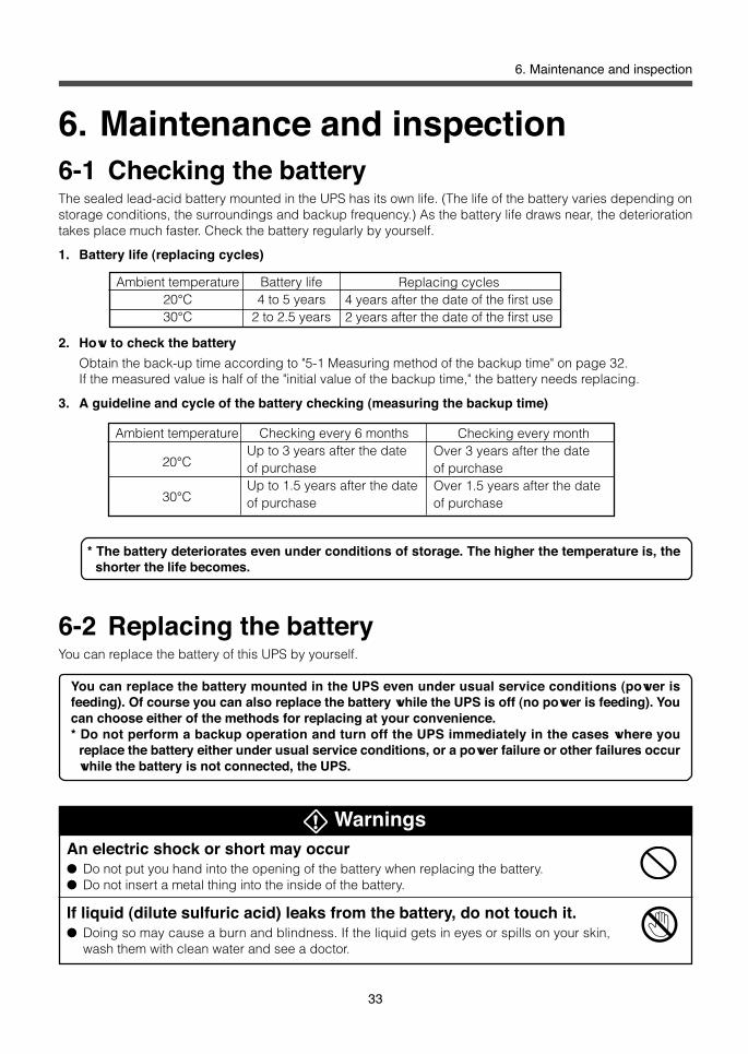
WarningsAn electric shock or short may occur● Do not put you hand into the opening of the battery when replacing the battery.● Do not insert a metal thing into the inside of the battery.
If liquid (dilute sulfuric acid) leaks from the battery, do not touch it.● Doing so may cause a burn and blindness. If the liquid gets in eyes or spills on your skin,
wash them with clean water and see a doctor.
Ambient temperature20°C30°C
Battery life4 to 5 years
2 to 2.5 years
Replacing cycles4 years after the date of the first use2 years after the date of the first use
Ambient temperature
20°C
30°C
Checking every 6 monthsUp to 3 years after the dateof purchaseUp to 1.5 years after the dateof purchase
Checking every monthOver 3 years after the dateof purchaseOver 1.5 years after the dateof purchase
6. Maintenance and inspection6-1 Checking the batteryThe sealed lead-acid battery mounted in the UPS has its own life. (The life of the battery varies depending onstorage conditions, the surroundings and backup frequency.) As the battery life draws near, the deteriorationtakes place much faster. Check the battery regularly by yourself.
1. Battery life (replacing cycles)
2. How to check the battery
Obtain the back-up time according to "5-1 Measuring method of the backup time" on page 32.If the measured value is half of the "initial value of the backup time," the battery needs replacing.
3. A guideline and cycle of the battery checking (measuring the backup time)
* The battery deteriorates even under conditions of storage. The higher the temperature is, theshorter the life becomes.
6-2 Replacing the batteryYou can replace the battery of this UPS by yourself.
You can replace the battery mounted in the UPS even under usual service conditions (power isfeeding). Of course you can also replace the battery while the UPS is off (no power is feeding). Youcan choose either of the methods for replacing at your convenience.* Do not perform a backup operation and turn off the UPS immediately in the cases where you
replace the battery either under usual service conditions, or a power failure or other failures occurwhile the battery is not connected, the UPS.

34
6. Maintenance and inspection
CautionsDo not short the battery with metal things● Doing so may cause a burn or fire.● A dead battery keeps some current remaining.
Do not toss a battery into the fire. Do not try to break a battery.● The battery may explode or dilute sulfuric acid may leak.
Do not use any batteries unless otherwise specified.● Doing so may lead to a fire.● Battery model: BP100XR
Do not use a new battery and an old battery all together● Dilute sulfuric acid may leak
Do not drop the battery or do not give strong impact on it.● Dilute sulfuric acid may leak.
Do not replace the battery near the place where there is flammable gas.● A spark may occur when connecting the battery, and lead to a fire.
Replace a battery on a structurally sound base.● Hold the battery securely with your both hands to avoid dropping.● Not doing so may cause injury due to failing, burns, or liquid (acid) leakage.
Do not carry the replaced battery pack upside down.● If liquid (dilute sulfuric acid) leaks from the battery, there is a danger of burns or blindness.
Do not disassemble or modify the battery.● Doing so may cause a leakage of dilute sulfuric acid, which may cause blindness and burns.
NotesThe UPS mounts a lead acid battery.The lead acid battery is recyclable.● Please recycle it when you replace it or discard the product you do not use any more. Pb
1. Procedures for the replacement of the BU100XR2 battery
1-1 Unscrew 2 screws that hold the left side ofthe front panel to the UPS.

35
6. Maintenance and inspection
1-2 Hold the handgrip of the front panel and slide the panel to the left q, and pull it toward you w andremove.
1-3 Unscrew the screw counterclockwise at the right upper side of where the front panel was removed q.Holding down the snap-on plug of the battery connecting cable w, pull the battery able toward youe.
1-4 Hold the white pullout label at the bottom of the battery pack and gradually pull out the battery pack.When you see a red tape stuck on the top of the battery pack, you can demount the battery bypulling it out 10cm further. Hold the battery securely with your both hands to avoid dropping.
w
q
e
q
w

36
6. Maintenance and inspection
1-5 Insert a fresh battery into the UPS as far as it will go q.Secure clockwise the screw at the right upper side of the battery pack w.• Battery pack for replacement
Type: BP100XR
1-6 Put the battery connecting cable plug in the receptacle of the UPS until it snaps on.A spark may occur but it does not indicate failure.
1-7 Hold and insert the lugs of front panel into the slots of the UPS q, slide the front panel to the right w,and secure two screws clockwise at the left side of the front panel.•Write the replacement date on the label at
the top of the UPS.• In a case where you use the UPS monitoring
software, input the replacement date of thenew battery.
•After the replacement of the battery, pressthe Start switch for over 20 seconds, andcarry out the self-diagnostic test at the timeof replacement of the battery. You will nothear a beep for the first 10 seconds, andeventually you will hear the beep every 10seconds. When the beep started to soundcontinuously, turn off the Start switch. Thatcompletes the replacement of the battery.
NoteDiscard the battery after replacing.* If you keep it for a long time, dilute sulfuric acid may leak from the old battery.* For information on discarding the battery, please contract us.
wq
w
q q
e

37
6. Maintenance and inspection
2. Procedures for the replacement of the BU200XR2 battery and add-onbattery units: MB100XR2/MB200XR2.
2-1 Unscrew 4 screws that hold both sides of the front panels to the battery unit.
2-2 Hold the handgrip of the left front panel and slide the left panel to the left q, and pull it toward you wand remove. In the same way, hold the handgrip of the right front panel and slide the right panel to theright e, and pull it toward you r. While holding snap-on cable connector attached to the panel, pullout the cable connector from the right front panel.
2-3 Unscrew the screw counterclockwise at the right upper side of the battery pack q. Hold the whitepullout label at the bottom of the battery pack and pull as far as you see a yellow tape stuck on the topof the battery pack w. Unhook the battery connecting cable while holding the battery pack.
q
w
e
q
w
e
r

38
6. Maintenance and inspection
2-4 Hold down the snap-on plug of the battery connecting cable q, and pull the cable w. Hold the whitepullout label and remove the battery pack e, and pull out the battery pack toward you.When you see a red tape stuck on the topof the battery pack, you can demount thebattery by pulling out the pack 10cmfurther. Hold the battery securely with yourboth hands not to drop it.Demount another battery pack in the sameway. Do not try to demount two battery packstogether. Doing so may cause dropping thebattery packs and injury as the center ofgravity of the battery packs leans toward thefront.
2-5 Insert a new battery pack into where you can hook the battery pack plug-in cable and the UPS connectorq.Insert the battery connecting cable plug into the connector of the UPS until it snaps on.A fire may occur but it does not indicate failure.•Battery pack for replacement
Type: BP100XR
2-6 Insert a new battery into the UPS as far as it will go q. Secure clockwise the screw at the right upperside of the battery pack w. Hook and insert another battery pack in the same way.
q
w
q
w

39
6. Maintenance and inspection
2-7 Hook the cable attached to the right front panel into the connecter.Hold and insert the lugs of the right front panel into the slots of the UPS q, slide the right front panel tothe left w. Slide the left panel to the right in the same way e.
2-8 Secure four screws at both sides of the front panels clockwise.• Write the replacement date on the label on the top of the UPS.• In a case where you use the UPS monitoring software, input the replacement date of the new battery.• After the replacement of the battery, press the Start switch for over 20 seconds, and carry out the
self-diagnostic test at the time of replacement of the battery. You will not hear a beep for the first 10seconds, and eventually you will hear the beep every 10 seconds. When the beep started to soundcontinuously, turn off the Start switch. That completes the replacement of the battery.
q q q q q
ew
NoteDiscard the battery after replacing.* I If you keep the old battery for a long time, dilute sulfuric acid may leak from the battery.* For information on discarding the battery, please contract us.

40
6. Maintenance and inspection
CautionsBefore maintaining devices connected to the UPS, turn off the UPS andremove the AC Input Plug from a wall outlet (commercial power).● Even if you remove the AC Input Plug during the operation of the UPS, the backup function of
the UPS keeps feeding power through the power supply output receptacle of the UPS.● In a case where the scheduled operation is ON and the AC Input Plug of the UPS is put in a
wall outlet (commercial power), the UPS starts feeding power at the starting time of thescheduled operation.
6-3 Cleaning1. Cleaning of the UPS
Damp a soft cloth with water or detergent, squeezes it tightly, and wipes the UPS lightly.Do not use chemicals such as thinner and benzene. (They cause deformation or discoloration.)
2. Removing dust from the AC Input Plug of the UPSTurn off all the devices linked to the UPS and the UPS, and remove the AC Input Plug from a wall outlet(commercial power).Then, remove dust with a dry cloth and make the plugging again.(For information on the connection, see "2. Installation and connector" on page 12.)
6-4 Cautions at the maintenance of devicesconnected to the UPS

41
7. Using the Network Line Surge Protection Function
7. Using the Network Link SurgeProtection Function
Line Surge Protection FunctionThis function is to absorb surge voltage (abnormally high voltage) that may occur on the telephone line ornetwork cable due to thunder. The function protects your modem, TA, and network card from surge damage.
* If you do not use the Network Line Surge Protection Function, this step is notrequired.
* Network Line Surge Protection Function does not comply with UL standard(UL497). If you require UL standard, do not connect telephone to Modem/TA/PCSide.
The following 2 types of connectors are available for the Network Line Surge Protection Function.• RJ45 (8-pins) and RJ11 (2-pins, 4-pins, or 6-pins)
7-1 When connecting to the telephone line or ISDNline
Connect the telephone line that comes out of the wall to the Line/Hub Side of the Network Line Surge Protectionof the UPS.Use the supplied telephone cable (modular cable) to connect between the Modem/TA/PC Side of the NetworkLine Surge Protection of the UPS and your modem, FAX and others DSU (or a terminal adaptor with built-inDSU).
7-2 When connecting to LAN 10Base-T/100 Base-TxTo protect your 10Base-T/100 Base-Tx (twisted pair cable without shielding) network interface, you need topurchase separately a cable equivalent to your cable in use.Connect the 10Base-T/100Base-Tx cable from HUB to the Line/Hub Side of the Network Line Surge Protectionof the UPS.Connect between the Modem/TA/PC Side of the Network Line Surge Protection and the network interface ofyou PC with the cable you purchased separately.

42
7. Using the Network Line Surge Protection Function
BU100XR2
BU200XR2
Modem, TA, LAN
Modem, TA, LAN
Telephone line, ISDN line, or 10Base-T/100Base-Tx
Telephone line, ISDN line, or 10Base-T/100Base-Tx
Connect to the Modem/TA/PC Side
Connect to the Line/Hub Side
Connect to the Modem/TA/PC Side
Connect to the Line/Hub Side
7-3 Example of connection

43
8. Using the UPS monitoring software and contact signal I/O
8. Using the UPS monitoring softwareand contact signal I/O
* If you do not use the UPS monitoring software and contact signal I/O, this step isnot required.
8-1 RS232C•Contact signal I/OThe RS232C/Contact Signal Connector I/O at the rear of the UPS provides both the function tocommunicate with the UPS monitoring software and the contact signal I/O function. There is nooption that you need to purchase separately.
8-2 When performing the auto shutdownprocessing by the UPS monitoring software
The preinstalled UPS monitoring software allows you to save files automatically and perform shutdown processingof your PC when a power failure occurs. However, the time between the occurrence of a power failure and thecompletion of the shutdown of your PC must be within the backup time measured in "5-1 Measuring method ofthe backup time" on page 32. For further information on the explanation and operation, refer to either the UPSmonitoring software instruction manual or the online help about the UPS monitoring software.
Scheduled operating mode using the UPS monitoring software● When making the settings of the scheduled operating mode, which turns off the UPS and opens the
circuit breaker to shut off commercial power at the same time, you must set the starting time shorter than90 days after the commencement of this scheduled operating mode.If you make the settings of the scheduled operating mode longer than 90 days, the internal timer is forcedto reset and the scheduled operation become disable.Notice that a dead battery gives you only about half of the setting time; approximately 45 days.If you make the setting of the scheduled operating mode longer than 90 days, you can press the Startswitch and get the UPS running, however, in case where the battery is dead, you may not be able to getyour UPS running again. When you are unable to get your UPS running, replace the battery according to"6-2 Replacing the battery" on page 33.
How to get your UPS running where it is set in scheduled operating mode throughthe UPS monitoring software● When you want to get your UPS running by pressing the Start switch under circumstances where your
USP is dead as it is set in the scheduled operating mode, just press the Start switch for at least 0.5second and your UPS enters into the usual service conditions after 15 seconds.
When you want to make a stop of your UPS, just press the Stop switch for at least 2 seconds.
Explanation
Pin configuration Pin number
123456789
RS232C signal name
T X DR X DP n PGNDP n PP n P
RING
5 4 3 2 1
9 8 7 6
Frot viewScrew diameter: inch screw #4-40 UNC
Contact signal nameBL
BS
GND
BU
DSUB 9P female

44
8. Using the UPS monitoring software and contact signal I/O
8-3 When performing the auto shutdown processingby the UPS Service of WindowsXP/2000
A standard UPS Service installed in WindowXP/2000 OS computers is available when you use the UPS Servicewith the connecting cable and special-purpose driver supplied with "PowerAssitant."
● Connection• DOS/V computers............Use the connecting cable supplied with "PowerAssistant."
Connect the RS232C/Contact Signal I/O Connector of the UPS and the RS232C port of the server/PC.
Auto restart after the completion of the OS shutdown processing through the UPSmonitoring software● For certain PC models (*1), they automatically restart immediately after the completion of the OS shut-
down processing through the UPS monitoring software in the event of a power failure.In this event, the UPS will probably make a stop during or after the restart of the PC, and files and harddisk mounted in your PC may be destroyed.You can avoid this problem by disabling POWER MANAGEMENT in the BIOS settings of your PC.* 1) certain PC models: It is reported that MICRON's Millennia Mme likely brings about the problem.
● When the PC does not startup automatically, select a "System startup at power return" setting(such as "Restore On AC/Power Loss) at the BIOS settings and change to a "Startup powerreturned system" setting (such as "Power On"). Individual BIOS setting method and/or displaymay differ depending on the PC. For more information, consult your instruction manual orcontact your technical support center.
● When considering a system with automatic startup at power return, choose a PC that satisfiedthe following conditions. For more information on PC operation at input power on, consultyour instruction manual or contact the PC technical suppoprt center.
<Condition>The PC starts up at input power on without depressing the power switch
Automatic shutdown of UPS● Due to RS232C signal voltage from PC, UPS may sop earlier than system shutdown time set
by automatic shutdown software after completion of OS shutdown.
Explanation
Notes● In the case of WindowsXP/2000 computers, you need to install special-purpose driver. You
can find the driver supplied with "PowerAssitant," or you can download the driver at
http://www.omron.co.jp/ped-j/index.html.
For the further information on how to install, see the supplied instruction manual.
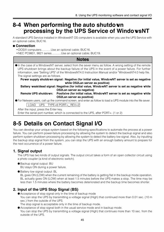
45
8. Using the UPS monitoring software and contact signal I/O
Notes● In the case of a WindowsNT server, select from the sever menu as follow. A wrong setting of the remote
UPS shutdown brings about the backup failure of the UPS in the event of a power failure. For furtherinformation, see "Setting UPS" of the WindowsNT4.0 Instruction Manual and/or "WindowsNT4.0 help file.The signal settings are as follows.
Power supply shutdown signal: Negative (for initial value, WindowNT server is set as negativewhile OS2Lan server as positive)
Battery weak/dead signal: Negative (for initial value, WindowNT server is set as negative whileOS2Lan server as negative)
Remote UPS shutdown: Positxive (for initial value, WindowNT server is set as negative whileOS2Lan server as positive)
● For Netware users, call up the command screen, and enter as follow to load a UPS module into the file sever.
LOAD UPS TYPE=6 PORT=_ REV=2
After the input, press the Enter key.Enter the serial port number, which is connected to the UPS, after PORT=. (1 or 2)
8-4 When performing the auto shutdownprocessing by the UPS Service of WindowsNT
A standard UPS Service installed in WindowsNT OS computers is available when you use the UPS Service withan optional cable; BUC16.
● Connection•DOS/V computers............Use an optional cable; BUC16.•NEC PC9801, 9821 series............Use an optional cable; BUC19.
8-5 Details on Contact Signal I/OYou can develop your unique system based on the following specifications to automate the process at a powerfailure. You can perform power-failure processing by allowing the system to detect the backup signal and alsoperform system shutdown processing by allowing the system to detect the battery low signal. Also, by inputtingthe backup stop signal from the system, you can stop the UPS with an enough battery amount to prepare forthe next occurrence of a power failure.
1. Signal outputThe UPS has two kinds of output signals. The output circuit takes a form of an open collector circuit usinga photo coupler (a kind of electronic switch).
● Backup signal output: BUBU stays ON during a power failure.
● Battery low signal output: BLBL goes ON (LOW) when the current remaining of the battery is getting flat in the backup mode operation.BL actually goes ON (LOW) when at least 1.5 minutes before the UPS makes a stop. The time may beless than 1.5 minutes where the battery becomes deteriorated and the backup time becomes shorter.
2. Input of the UPS Stop Signal (BS)● Acceptance of stop signal only in the time of backup mode
You can stop the UPS by transmitting a voltage signal (High) that continued more than 0.01 sec. (10 msec.) from the outside of the UPS.The stop signal is acceptable only in the time of backup mode.
● Acceptance of stop signal both in the usual service mode and in backup mode.You can stop the UPS by transmitting a voltage signal (High) that continues more than 10 sec. from theoutside of the UPS.

46
8. Using the UPS monitoring software and contact signal I/O
3. Connection to the systemPlease design a cable wiring by yourself.(For the samples of the circuit, see "7. Example of connection: the Contact Signal I/O Circuit" on page 46.)
4. Contact Signal I/O ratings● Signal output (BU and BL)
Photo coupler ratingsApplied voltage: 24VDC or lessMaximum current: 10mA
● Signal input (BS)Input voltage: HIGH 5 to 12VDC, LOW 0.8VDC or less• BS is acceptable both in usual service mode and backup mode.
BS becomes unacceptable when voltage signal continues over 10 seconds.•BS is acceptable only in backup mode.
BS becomes unacceptable when voltage signal continues over 0.01 second (10ms).* For further information on the setting of the UPS Stop Signal, see "9-1 Functions that can be set/
change from the UPS” on page 47.
5. Contact Signal I/O circuit insidethe UPS
6. Example of the use of the Contact Signal I/O circuit
8-6 Precautions and notes on the use of theContact Signal I/O
NotesWhen connecting a device that generates counter electromotive force such as a relay to the signal outputcircuit, connect a diode to prevent counter electromotive force across the relay.
Explanation● After shutdown processing and recovery from a power failure, the UPS automatically restarts and supplies
power. If you do not want to start the devices connected to the UPS, turn off their switches in advance.● The UPS monitoring software allows you to disable the automatic restart.
● Example of the use of the BU signal ● Example of the use of the BS signal
To port on PC
Connecting cable(twisted or shielded)
12V1K
System side
GND
BU TLP627
BS
C2458
GND
12V 1K TLP521
GND
To port on PC
Connecting cable(twisted or shielded)
System side
1.2K
BU
BL
BS
2.4V 560

47
9. EChanging the setting of the functions
9. Changing the setting of the functionsThe UPS provides the following setting functions. The settings are maintained even after the UPS is shut down.
9-1 Functions that can be set/change from the UPS● Changing the acceptance conditions of the Backup Stop Signal (BS).
You can select the acceptance conditions of the Backup Stop Signal from either of two modes as below.* "Accept only during Battery mode"* "Accept both during line mode and during Battery mode"
Notes
Setting the acceptance conditions of the Backup Stop Signal (BS)● The factory- setting is "Accept only during Battery mode."
Do not change the factory-setting except when the UPS is under the following conditions.Also do not change the factory-setting when using the supplied UPS monitoring software,PowerAssistant.• If you change the setting of "Accept both during line mode and during Battery mode." The UPS can make
an accidental stop at the startup of the PC, which may break files and others.It is reported that the problem occurs when an expansion SCSI board is added to Sony VAIO R seriesPC.
•Do not start up the PC during the battery mode. The UPS will make a stop at the startup.
● Changing the factory-settingWhen you always want to restart your system as an automatic system, for examples, Windows NT'sUPS service that enables you to perform auto save processing, the contact signal that enables youto configure a shutdown system, and others, change the settings of "Accept both during line modeand during battery mode."• In a case you want to run the WindowsNT UPS Service, you will always need to change the factory-
settings, otherwise WindowsNT's power reset and auto restart functions become out of control. Theseproblems usually take place when irregularities in the mains supply are restored before the UPS comesto a stop, which follows a power failure shutdown.
•When you change the setting, the UPS may stop at the startup of the PC, however, it depends on PCmodels.Before beginning the first run of the system, check whether the UPS comes a stop at the startup of yourPC and go through a series of steps below.
* Checking steps1. Remove the AC plugs of the devices such as PC and peripheral devices from the Power Supply Output
Receptacles of the UPS.2. Put the plugs of PC and peripheral devices in a wall outlet (commercial power).3. Connect the serial port of PC and the UPS.4. Start up PC.
Check whether the UPS comes to a stop or not.* In the case where the UPS keeps running, then you may select the "Accept both during line mode and
during battery mode" setting.In the case where the UPS come to a stop, select "Accept only during Battery mode" setting beforeuse.
* Check whether there are no problems with the UPS, and put the AC plugs of PC and peripheraldevices.For further information on the connection, see "2. Installation and connection" on page 12.

48
9. Changing the setting of the functions
● Setting steps1. Unplug the UPS and let it to a standstill. Press the Start switch for at least 0.5 second while pressing and
holding Stop switch.
2. The AC Input Lamp blinks and the Bypass Mode Lamp orthe Battery Mode Lamp goes on.
3. Under the condition, press and hold the Start Switch againfor at least 0.5 second. Either of the Bypass Mode Lamp orthe Battery Mode Lamp turns on, and let the setting change.
• The Bypass Mode Lamp lights up:It lets the UPS accept the signal both during line modeand battery mode.You can bring the UPS into a standstill by the voltage sig-nal, which continues at least 10 seconds.
• The Battery Mode Lamp lights up:It lets the UPS accept the battery mode only.You can bring the UPS into a standstill by voltage signal,which continues at least 0.01 second (10 ms).
* Factory-setting: Accept BS signal only during Batterymode.
4. When the desired setting is displayed, press and hold the Stop switch for at least 2 seconds, and then thesetting is completed.
9-2 Functions that can be set/change from theUPS monitoring software
1. Beeper ON/OFF setting
ON : The beeper sounds when an alarm is necessary.
OFF : Let the beeper disable.
* Factory-setting: ON
2. Auto battery test ON/OFF
ON : The battery test is automatically executed every 4 weeks.
If the test decides that the battery needs replacing, the UPS generates a replacement alarm.
OFF : The battery test, which is executed automatically at intervals of 4 weeks, comes to a standstill.
Set the test OFF in the cases where you want to let the automatic battery test and battery modecome a standstill.
* Factory-setting: ON
3. Auto restart ON/OFF
ON : The UPS startup automatically and starts to feed power at the time when the commercial power isrestored. It always takes place after the UPS is shut down through UPS monitoring software or thecontact signal in the event of power failures.
OFF : The UPS will not startup automatically at the time when the commercial power is restored followingthe shutdown of the UPS through UPS monitoring software or the contact signal. You only can startup the UPS manually by pressing the Start switch.
* Factory-setting: ON
バックアップ 運転
AC入力
異常 接続容量 オーバー
バッテリ 交換
バイパス 運転
バッテリ 残量
テスト/ブザー停止 電源出力
運転
停止
Light is blink on
Light is off
Light is on or off depending on the status.

49
9. EChanging the setting of the functions
Remedies
The AC Input Plug is not put in a wall outlet.• Check whether the AC Input Plug is certainly put in a wall outlet.
The red button pops up from the AC Input Overcurrent Protection. (BU100XR2)The AC Input Overcurrent Protection is OFF. (BU200XR2)
• It is suspected that too many devices are connected to the UPS, or the devicesdeveloped a short circuit. Reduce connected devices or check the fuses ofdevices.In a case where the devices connected to the UPS are normal, then disconnect allof the devices from the UPS, turn on the Red button of the AC Input Overcurrentprotection and put the AC Input Plug in a wall outlet (commercial power). In casethat the AC Input Overcurrent Protection still remains OFF, you may assume a fail-ure.
It is suspected that the battery is not changed fully.• Turn off every device linked to the UPS and charge the UPS for at least 8 hours.
After the completion of the battery charge, bring the UPS and every device linkedto the UPS to a standstill, and turn on the Start switch again.Remove the ACA Input Plug from a wall outlet (commercial power).In case where the battery mode does not function at all, replace the battery packas the life of the battery expired.
Voltage fluctuations at low voltage level occur frequently or the voltage containsnoises, which bring about an extreme distortion of the voltage waveform.• Change the wall outlet (commercial power) to which you put the plug of the UPS.
Plug the UPS in other wall outlet (commercial power) at some distance away fromthe devices that consumes large power.
• The similar problem may occur also when you put many devices in a plug strip orextension cord plugged in the UPS as well.
It is assumed that a noise occurred inside of the UPS causes jitter and white lines ofthe display.• Ground the UPS and every device linked to the UPS. Put them in a grounding-type
receptacle (commercial power), or a receptacle with a grounding terminal.• The problems may occur where a power cord is too long, some of the power cords
are adjacent to one another, or the UPS and devices to linked to the UPS are adja-cent one another. Change the placement of the UPS and devices
• If the UPS or devices connected to the UPS are placed in a metal rack, ground therack.
The total capacity of the devices connected to the Power Supply Output Recep-tacles of the UPS exceeds the rated capacity; 1 KVA/700W for BU100XR2 or 2KVA/1.4KW for BU200XR2.• Reduce connected devices.
The auto battery test indicated that the life of the battery expired.• The battery mode cannot be functioned and therefore replace the battery pack.
An error or faulty has occurred in the UPS.• Bring the UPS and the devices connected to the UPS to a standstill.
Remove every device connected to the UPS, and then turn on the Start switch ofthe UPS. In the case the UPS restores in usual service condition, it is assumed thatthe some of the devices linked to the UPS developed a short circuit. Check de-vices.In the case where the problem still persists, bring the UPS to a standstill for onehour, and then restart the UPS. In a case where the UPS restores in usual servicecondition, it is assumed temperature rise, then improve ventilation around the UPS.Finally if you cannot solve the problem after one hour, it is assumed that the UPSmay be out of order and need repair.Contact us:
It is assumed that output fuse is burnt.• Stop operation of UPS and check the output fuse.
Replace the fuse if it is burnt.
10. TroubleshootingProblems
The UPS does not operate, or theAC Input Lamp does not go on.
Battery mode does not function.The devices connected the UPScomes to a stop when a powerfailure occurs.
The UPS enters into the batterymode frequently
The display of devices linked tothe UPS is abnormal.• Jitter of the display• While lines of the display
The Connection CapacityExceeded Lamp goes on.
The Battery Replacement Lampgoes on.
The Error Lamp goes on.
No output despite operationmode indication is normal(For BU200XR2 only)

50
9. Changing the setting of the functions
Operationmethod
Input
Output
Battery
Environ-ment
Standards
Others
Operation methodCooling method
Rated voltage range
FrequencyMaximum current
Number of phasesRated capacity
Output waveformFrequency/accuracy
Number of phasesOverload protection
Switching time (at power failure)Bypass switching timeBypass switching is possibleRange of input current
TypeVoltage
Capacity/quantity
Backup timeCharging methodCharging time
Operating ambient temperatureOperating ambient humidityStorage temperatureStorage humidityWithstand voltageInsulation resistanceLeak currentThunder surge resistance
Safety standardVCCIInput harmonics
Internal powerconsumption
NoiseOuter dimension (mm)
Weight
ReferencesA. Specifications
References
At the time of over 75% loadingAt the time of below 75% loading
Bu100XR2BU200XR2
Bu100XR2BU200XR2
Auto retransfer system
At startup, Under abnormalconditions, excessive capacity,Under abnormal conditions,excessive capacity,
Bu100XR2BU200XR2Bu100XR2BU200XR2Initial value 20°C, Rated load
80% for 4 hours
500VDC
BU100XR2BU200XR2
BU100XR2BU200XR2 (main unit)MB1002/MB200XR2 (Battery unit)BU100XR2BU200XR2 (main unit)MB1002/MB200XR2 (Battery unit)
Full-time inverter power supply methodForced air cooling method
87 to 120VAC72 to 120VAC50/60Hz10.2A20A
Single phase 2 lines1KVA/700W2KVA/1.4KW100AVC ± 3%Sine waveIn synch with input frequency (Line mode)50/60Hz ± 1Hz (Battery mode)Single phase 2 linesWarning through the beeper and display at thetime of rated capacity or greater
Switched to the bypass mode when 105% orlarger of rating continues for 3 minutes or over
Switched to the bypass mode when 125% orlarger of rating continues for 30 seconds or over
Switched immediately to the bypass mode when150% or larger takes place
Non intermittent
4msec or less80 to 115ACV
Sealed lead-acid battery36V72V7.2Ah/12V X 3 packs7.2Ah/12V X 6 packs5 minutes (at rated load)Constant voltage constant current charging8 hours (20°C)
0 to 40°C
25 to 85%RH-15 to 40°C20 to 90%RH1500VAC, 1 one minute10M ohm or more1mA or lessTo ground 4KV/between lines 20KV
Complied with UL1778Adherence to Class AIEC1000-3-2
170W or less330W or less50dB or lessW440 X D445 X H88W440 X D426 X H8819 Kg12 Kg26 KgW440 X D445 X H88

51
References
< mm >B. Dimensional outline drawings
440
445
88
Lubber seat height: 18mm
BU100XR2 BU200XR2 (main unit)
Rackmount fittingsMB100XR2MB200XR2Battery unit
88440
φ5.0
440 88
445
426
440 88
445
3.0
52.0
19.0 25.0
21.3
12.5
7.8
40.0
85.0
56.0

52
References
●Replacing battery pack of both BU100XR2 and BU200XR2
●Add-on battery unit for BU100XR2
●Add-on battery unit for BU200XR2
●Cable for Windows NT UPS service (For DOSV)
●Cable for Windows NT UPS service (For NEC PC9800,9821 series)
●Powerassistant, BUC16, BUC19, Extension cable (4.5m)
D. Optional parts and productsThe following optional devices and parts are available. For further information, see general catalogs of Omron's peripheraldevices.
C. Circuit block diagram
100 VACinput Input overcurrent
protection
Noisefilter
Power supplyrelay
Chargingcircuit
Rectifier(high power
factorconversion)
Step-upconverter
Battery
Commercial powerbypass output
Inverter(sinewave)
Filter
Outputswitching
Power supplyoutput:100VAC
At startup/capacity exceeded/errorDuring line modeDuring Battery mode
Controlcircuit Power supply switch
(Model: BP100XR)
Unit (BU100XR2), inner battery and anequivalent-size of two add-on batteries(Model: MB100XR2)
Unit (BU200XR2), inner battery and anequivalent-size of one add-on battery(Model: MB200XR2)
(Model: BUC16)
(Model: BUC19)
(Model: BUC17)

BU100/200XR2-B
No part or whole of this manual may be reproduced without permission.The contents of this manual are subject to change without notice.
OMRON Corporation