Embed Size (px)
Citation preview

________________________________________________________________________________
Ultrastab 866 Precision Current Transducer
User Manual
Distributed by: GMW Associates 955 Industrial Road, San Carlos, CA 94070 USA Tel: (650) 802-8292 Fax: (650) 802-8298
Email: [email protected] Website: http:/www.gmw/com Manufactured by: Danfysik A/S Mollehaven 31 DK 4040 Jyllinge Denmark Tel: +45 46 76 81 50 Fax: 45 46 73 15 51 Email: [email protected] File Name: DF_MAN_866.pdf, Rev date: 12 Feb 2002
GMW 955 Industrial Road, San Carlos, CA 94070 Tel: (650) 802-8292 Fax: (650) 802-8298 Email: [email protected] Web site: http://www.gmw.com

________________________________________________________________________________
GMW 955 Industrial Road, San Carlos, CA 94070 Tel: (650) 802-8292 Fax: (650) 802-8298 Email: [email protected] Web site: http://www.gmw.com
The ULTRASTAB 866 Current Transducer is the latest model in the DANFYSIK Current Transducer program. It is the first transducer of its class with transducer head and SMD based electronics integrated in one assembly.
The model 866 is based on the proven high performance current measurement system in the ULTRASTAB program, and it is used as a current feed back element in precision power supplies or gradient amplifiers.
It ranges 0-600A from DC to 100 kHz with a temperature coefficient lower than 1 ppm/°C. Powered with ±15V it produces an analog current of 400mA at 600 A primary current.
Output noise and noise feed back to the main conductor are both extremely low, and electro-static shielding ensures maximum immunity against external electrostatic fields.
THE 866 FEATURES
* Bandwidth DC to 100 kHz * Linearity better than 1 ppm * Absolute calibration traceable to NIST • Temperature coefficient less than • 0.3 ppm/°C
* Resolution better than 0.05 ppm * Bipolar, up to 400mA output current at * 600A primary current * Low noise on the output signal * Noise feed back to main conductor < 10µV
APPLICATIONS: * Feed back element in high performance gradient
amplifiers * Feed back element in precision current regulated
power supplies
________________________________________________________________________________
GMW 955 Industrial Road, San Carlos, CA 94070 Tel: (650) 802-8292 Fax: (650) 802-8298 Email: [email protected] Web site: http://www.gmw.com
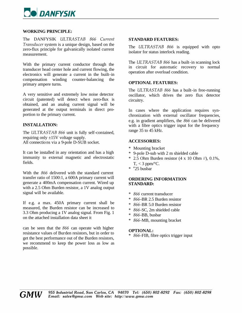
WORKING PRINCIPLE:
The DANFYSIK ULTRASTAB 866 Current Transducer system is a unique design, based on the zero-flux principle for galvanically isolated current measurement. With the primary current conductor through the transducer head center hole and current flowing, the electronics will generate a current in the built-in compensation winding counter-balancing the primary ampere turns. A very sensitive and extremely low noise detector circuit (patented) will detect when zero-flux is obtained, and an analog current signal will be generated at the output terminals in direct pro-portion to the primary current. INSTALLATION:
The ULTRASTAB 866 unit is fully self-contained, requiring only ±15V voltage supply. All connections via a 9-pole D-SUB socket. It can be installed in any orientation and has a high immunity to external magnetic and electrostatic fields. With the 866 delivered with the standard current transfer ratio of 1500:1, a 600A primary current will generate a 400mA compensation current. Wired up with a 2.5 Ohm Burden resistor, a 1V analog output signal will be available. If e.g. a max. 450A primary current shall be measured, the Burden resistor can be increased to 3.3 Ohm producing a 1V analog signal. From Fig. 1 on the attached installation data sheet it can be seen that the 866 can operate with higher resistance values of Burden resistors, but in order to get the best performance out of the Burden resistors, we recommend to keep the power loss as low as possible.
STANDARD FEATURES:
The ULTRASTAB 866 is equipped with opto isolator for status interlock reading. The ULTRASTAB 866 has a built-in scanning lock in circuit for automatic recovery to normal operation after overload condition. OPTIONAL FEATURES:
The ULTRASTAB 866 has a built-in free-running oscillator, which drives the zero flux detector circuitry. In cases where the application requires syn-chronization with external oscillator frequencies, e.g. in gradient amplifiers, the 866 can be delivered with a fibre optics trigger input for the frequency range 35 to 45 kHz. ACCESSORIES:
* Mounting bracket * 9-pole D-sub with 2 m shielded cable * 2.5 Ohm Burden resistor (4 x 10 Ohm //), 0.1%,
Tc < 3 ppm/°C. * ø25 busbar ORDERING INFORMATION STANDARD: * 866 current transducer * 866-BR 2.5 Burden resistor * 866-BR 5.0 Burden resistor * 866-SC, 2m shielded cable * 866-BB, busbar * 866-MB, mounting bracket OPTIONAL: * 866-FIB, fibre optics trigger input

________________________________________________________________________________
GMW 955 Industrial Road, San Carlos, CA 94070 Tel: (650) 802-8292 Fax: (650) 802-8298 Email: [email protected] Web site: http://www.gmw.com
ULTRASTAB 866-150 CURRENT TRANSDUCER
BASIC SPECIFICATIONS
Primary current I (max.)
0-150A
Polarity
Bipolar
Output current (max.)
0-200 mA
Overload capacity: Normal operation Basic function maintained Fault
100% 110%
500% (0.1 s.) External Burden resistor - see fig. 1: Max. Min.
100 ? 5 ?
Current transfer ratio
750:1
Linearity
< 1 ppm
Measuring/ratio stability: Initial v.s. temperature v.s. time
< 2 ppm < 0.3 ppm/ °C
< 1 ppm/month Offset: Initial v.s. temperature
8 µA 0.1 µA/°C
Output noise (RMS): DC - 10 Hz DC - 10 kHz DC - 50 kHz
< 0.04 µA < 2.4 µA < 8 µA
Feedback noise (RMS), DC - 50 kHz (measured on the primary current cable – one turn)
< 10 µV (typical 5 µV) Busbar free zone (from center)
r = 70 mm

________________________________________________________________________________
GMW 955 Industrial Road, San Carlos, CA 94070 Tel: (650) 802-8292 Fax: (650) 802-8298 Email: [email protected] Web site: http://www.gmw.com
ULTRASTAB 866-150 CURRENT TRANSDUCER
BASIC SPECIFICATIONS Slew rate (10-90%)
> 10 kA/ms
Bandwidth (3 dB, small signal 0.5%)
DC to 100 kHz
Test voltage (pin 4 - ground to a ø25 busbar)
5 kV AC (RMS)
Operating temperature
10 – 50°C
Input power requirement
Max. power consumption 5 VA
±15 V regulated < ±5% 200 mA + compensation current
Mechanical dimensions 866 assembly: Weight
122 x 98 x 57 mm
hole for busbar or cable: ϕ 26 mm
approx. 1 kg
Optional feature: Input for 35-45 kHz oscillator trigger signal via fibre optics (HP-HFBR2521).
All ppm figures refer to max. output. Specifications are subject to change without notice. We recommend that a shielded output cable and plug are used to ensure the maximum immunity against electrostatic fields. 9-pole D-SUB Pin configuration: Pin 1 (For factory use only)
Pin 2 (Test pin for zero detector - factory use only) Pin 3 Normal operation status - opto coupler - Pin 4 GND and electrostatic shield Pin 5 -15 V / 50mA + compensation current Pin 6 Current output Pin 7 (For factory use only) Pin 8 Normal operation - opto coupler + Pin 9 +15 V /200 mA + compensation current

________________________________________________________________________________
GMW 955 Industrial Road, San Carlos, CA 94070 Tel: (650) 802-8292 Fax: (650) 802-8298 Email: [email protected] Web site: http://www.gmw.com
ULTRASTAB 866-600 CURRENT TRANSDUCER
BASIC SPECIFICATIONS
Primary current I (max.)
0-600A
Polarity
Bipolar
Output current (max.)
0-400 mA
Overload capacity: Normal operation Basic function maintained Fault
100% 110%
500% (0.1 s.) External Burden resistor - see fig. 1: Max. Min.
100 ? 2.5 ?
Current transfer ratio
1500:1
Linearity
< 1 ppm
Measuring/ratio stability: Initial v.s. temperature v.s. time
< 2 ppm < 0.3 ppm/ °C (0.120 µA)
< 1 ppm/month (0.060 µA) Offset: Initial v.s. temperature
< 20 ppm (8 µA) < 0.2 ppm (0.1 µA/°C)
Sensivity to power supply changes
< 1.5 ppm/%
Output noise (RMS): DC - 10 Hz DC - 10 kHz DC - 50 kHz
<0.05 ppm (0.02 µA) <3 ppm (1.2 µA) <10 ppm (4 µA)
Feedback noise (RMS), DC - 50 kHz (measured on primary cable – one turn)
< 10 µV (typical 5 µV) Busbar free zone to be within linearity specification:
Cylinder shape (diameter x length)
Ø 150 x 150 mm

________________________________________________________________________________
GMW 955 Industrial Road, San Carlos, CA 94070 Tel: (650) 802-8292 Fax: (650) 802-8298 Email: [email protected] Web site: http://www.gmw.com
ULTRASTAB 866-600 CURRENT TRANSDUCER
BASIC SPECIFICATIONS
Slew rate (10-90%)
> 10 kA/ms
Bandwidth (3 d B, small signal 0.5%)
DC to 100 kHz
Test voltage (pin 4 - ground to a ø25 busbar)
5 kV AC (RMS)
Operating temperature Storage temperature
10 – 50°C
0 – 60°C Input power requirement
Max. power consumption 10 VA
±15 V regulated < ±5% 200 mA + compensation current
Emission complying standard Immunity complying standard
EN 50081-2 EN 50082-2-1995
Operating humidity
20 – 80%
Mechanical dimensions 866 assembly: Weight
122 x 98 x 57 mm
hole for busbar or cable: ϕ 26 mm
approx. 1 kg
Optional feature: Input for 35-45 kHz oscillator trigger signal via fibre optics (HP-HFBR2521).
All ppm figures refer to max. output. Specifications are subject to change without notice. We recommend that a shielded output cable and plug are used to ensure the maximum immunity against electrostatic fields. 9-pole D-SUB Pin configuration: Pin 1 (For factory use only)
Pin 2 (Test pin for zero detector - factory use only) Pin 3 Normal operation status - opto coupler - Pin 4 GND Pin 5 -15 V Pin 6 Current output Pin 7 (For factory use only) Pin 8 Normal operation - opto coupler + Pin 9 +15 V House Electrostatic shield

Ultrastab 866 Precision Current Transducer
12 February 2002
________________________________________________________________________________
GMW 955 Industrial Road, San Carlos, CA 94070 Tel: (650) 802-8292 Fax: (650) 802-8298 Email: [email protected] Web site: http://www.gmw.com
VOM-Voltage Output Module
SPECIFICATIONS
Slew rate (10-90%)
600A
Output voltage:
Bipolar ± 10V
Offset Initial: vs. temperature:
< 10 ppm <5 ppm
Gain Initial: vs. temperature:
< 50 ppm < 6ppm /°C
Linearity:
< 50 ppm
Bandwidth: (3dB)
DC-100kHz

Ultrastab 866-600A Installation 12 April 2002
_____________________________________________________________________________
GMW
955 Industrial Road, San Carlos, CA 94070 Tel: (650) 802-8292 Fax: (650) 802-8298 Email: [email protected] Web site: http://www.gmw.com
The Wiring diagram shows: - Power connections - Connection of Burden Resistor ( Rb ) - Connection of opto-coupler output ( status ) Re. Status: Normal Operation means:
- +/- 15V present - - Zero detectors are working. - Output Current < 110%.
The Wiring diagram shows: - Power connections - Connection of Burden Resistor (Rb ) - Connection of opto-coupler output (status ) Re. Status: Normal Operation means:
- +/- 15V present - Zero detectors are working. - Output Current < 110%.
The graph shows the maximum Voltage that can Be achieved across the externally connected Burden Resistor as a function of the Primary Current.
The Graph shows the relationship between the Burden Resistor and the Primary Current.
0
2
4
6
8
10
VO
LT
50 100 150 200 250 300 350 400 450 500 550 600PRIMARY CURRENT (A)
MAX BURDEN RESISTOR VOLTAGE
0.0
20.0
40.0
60.0
80.0
100.0
OH
M
50 100 150 200 250 300 350 400 450 500 550 600PRIMARY CURRENT (A)
MAX BURDEN RESISTOR VALUE
Shielded Cable ULTRASTAB 866 User Side
6 9 5 4
8
3
D - SUB-9
Cable Shield
Imax = 6mA
Rb
Optocoupler Output
Current Output
ON = Normal Operation
+15V -15V
+VCC
GND
1
7
2
0V
Part No: SP10381 Blue Purple/Violet Brown Green Black White
Yellow
Orange
Red
Electrostatic Shielding

ULTRASTAB 866 Precission Current Transducer
Primary current: 0 – 600A Temp. coefficient: # 0.3 ppm Resolution: # 0.05 ppm Linearity: # 1 ppm Ratio: 1500:1
Noise Spectrum
-
0.5
1.0
1.5
2.0
2.5
3.0
3.5
4.00.1 1.0 10.0 100.0 1´000.0 10´000.0 100´000.0
Frequency [Hz]
RM
S n
ois
e [p
pm
]

Ultrastab 866-VOM INSTALLATION April 10, 2002
GMW
955 Industrial Road, San Carlos, CA 94070 Tel: (650) 802-8292 Fax: (650) 802-8298 Email: [email protected] Web site: www.gmw.com
The Wiring diagram shows:
- Power connections - Connection of voltage output - Connection of opto-coupler output ( status )
Re. Status: Normal Operation means: +/- 15V present
Zero detectors are working.
U out sense (pin 1) must be connected as shown for correct operation.
U L T R A S T A B 8 6 6 - V O M X X
6
9
5
4
8Optocoup le r
O N = N o r m a l O p e r a t i o n
1
2
Elect ros ta t ic Shie ld
V +
V -
0
U out sense
U ou t +
U ou t -
V
P o w e rSupply
Normal ope ra t ion = "L"6 m A m a x
U s e r s i d e
7
3
D-sub 9p male
Black
Blue
Orange
B r o w n
Green
Purple /Viole t
Ye l low
R e d
White
Shield
Sh ie lded Cab leP a r t N o : S P 1 0 3 8 1
-15V
0
+15V
+


FIRST ANGLEPROJECTION
8820
1G.
.
.
MK
20.
03.0
1
1:1
±0.3
---
G
A3
1
1
TS TS.KP
11.
03.9
7
CU
RR
EN
T T
RA
NS
DU
CE
R15
0/60
0AU
LTR
AS
TA
B 8
66
DK
-404
0 JY
LLIN
GE
DE
NM
AR
K. T
ELE
PH
ON
E: +
45 4
6 78
81
50. T
ELE
FA
X: +
45 4
6 73
15
51. E
-MA
IL: D
AN
FY
SIK
@D
AN
FY
SIK
.DK
IMP
OR
TA
NT
!T
his
docu
men
t con
tain
s in
form
atio
n w
hich
is
the
prop
orty
of D
anfy
sik
A/S
, Den
mar
k. It
is
subm
itted
to y
ou in
con
fiden
ce th
at it
will
not
be
dis
clos
ed o
r tr
ansm
itted
to o
ther
s w
ithou
t D
anfy
sik'
s au
thor
izat
ion.
TO
LER
AN
CE
:S
CA
LE:
SU
RF
AC
E T
RE
AT
ME
NT
:M
AC
HIN
ING
:M
AT
ER
IAL:
DR
AW
N B
YD
ES
IGN
AP
P.
PR
OD
.AP
P.
PR
OJ.
EN
GR
.D
WG
.NO
.:
RE
VIS
ION
:
DA
TE
:
SH
EE
T
O
F
SIZ
E:
PR
OJE
CT
NO
.C
US
TO
ME
R:
FIL
E:

FIRST ANGLEPROJECTION
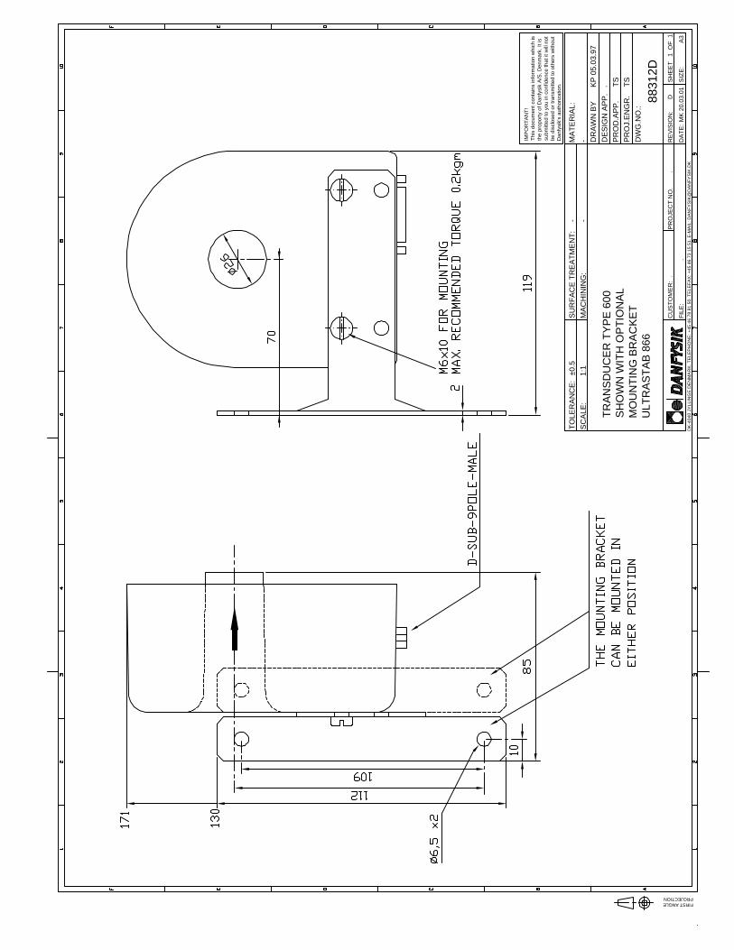
8831
2D.
.
.
MK
20.
03.0
1
1:1
±0.5
---
D
A3
1
1
TS TS.KP
05.
03.9
7
TR
AN
SD
UC
ER
TY
PE
600
SH
OW
N W
ITH
OP
TIO
NA
LM
OU
NT
ING
BR
AC
KE
TU
LTR
AS
TA
B 8
66
DK
-404
0 JY
LLIN
GE
DE
NM
AR
K. T
ELE
PH
ON
E: +
45 4
6 78
81
50. T
ELE
FA
X: +
45 4
6 73
15
51. E
-MA
IL: D
AN
FY
SIK
@D
AN
FY
SIK
.DK
IMP
OR
TA
NT
!T
his
docu
men
t con
tain
s in
form
atio
n w
hich
is
the
prop
orty
of D
anfy
sik
A/S
, Den
mar
k. It
is
subm
itted
to y
ou in
con
fiden
ce th
at it
will
not
be
dis
clos
ed o
r tr
ansm
itted
to o
ther
s w
ithou
t D
anfy
sik'
s au
thor
izat
ion.
TO
LER
AN
CE
:S
CA
LE:
SU
RF
AC
E T
RE
AT
ME
NT
:M
AC
HIN
ING
:M
AT
ER
IAL:
DR
AW
N B
YD
ES
IGN
AP
P.
PR
OD
.AP
P.
PR
OJ.
EN
GR
.D
WG
.NO
.:
RE
VIS
ION
:
DA
TE
:
SH
EE
T
O
F
SIZ
E:
PR
OJE
CT
NO
.C
US
TO
ME
R:
FIL
E: