Embed Size (px)
Citation preview

Ultrasonic compact heat and heat/cooling energy metersWS.5.., WS.6..
Ultrasonic heat meters to measure flow and energy in hydronic heating or cool-ing circuits.● Non-wearing due to non-moving parts● Approved in accordance with EN 1434 and MID accuracy class 2● Compact meter with flow measuring section
– WS.5.. made of high-tech plastic– WS.6.. made of brass
● Any mounting position (horizontal or vertical)● Mounting location can be changed one time (preset for return)● Measuring range of flow 1:100 conforming to EN 1434 (total range 1:1000)● Optical interface as per EN 62056-21● M-bus wired or M-bus RF communication● Available as pure heat energy meters, cooling energy meters (optional) as as a
combined heat/cooling energy meters● Self-diagnostics
CE2N5372en Smart Infrastructure
2021-08-09
2
Smart Infrastructure CE2N5372en
2021-08-09
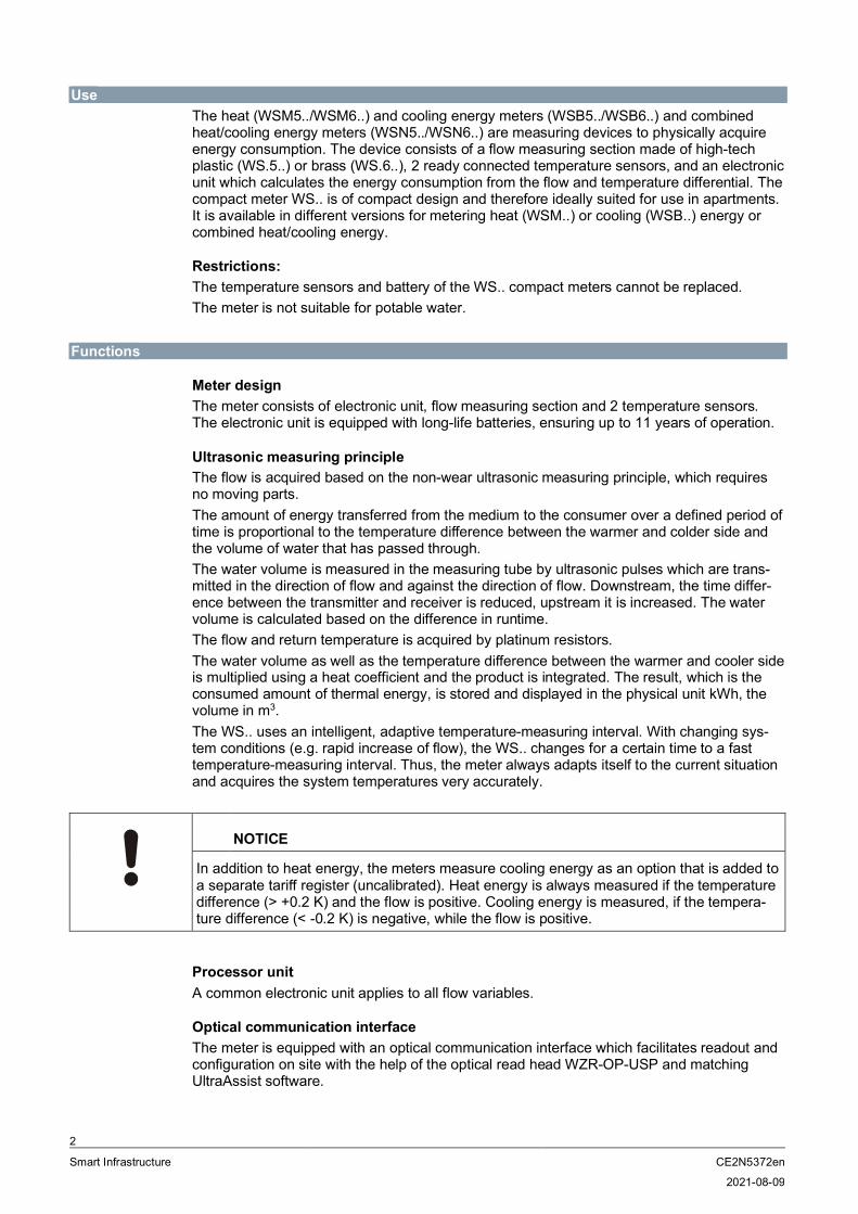
UseThe heat (WSM5../WSM6..) and cooling energy meters (WSB5../WSB6..) and combinedheat/cooling energy meters (WSN5../WSN6..) are measuring devices to physically acquireenergy consumption. The device consists of a flow measuring section made of high-techplastic (WS.5..) or brass (WS.6..), 2 ready connected temperature sensors, and an electronicunit which calculates the energy consumption from the flow and temperature differential. Thecompact meter WS.. is of compact design and therefore ideally suited for use in apartments.It is available in different versions for metering heat (WSM..) or cooling (WSB..) energy orcombined heat/cooling energy.
Restrictions:The temperature sensors and battery of the WS.. compact meters cannot be replaced.The meter is not suitable for potable water.
Functions
Meter designThe meter consists of electronic unit, flow measuring section and 2 temperature sensors.The electronic unit is equipped with long-life batteries, ensuring up to 11 years of operation.
Ultrasonic measuring principleThe flow is acquired based on the non-wear ultrasonic measuring principle, which requiresno moving parts.The amount of energy transferred from the medium to the consumer over a defined period oftime is proportional to the temperature difference between the warmer and colder side andthe volume of water that has passed through.The water volume is measured in the measuring tube by ultrasonic pulses which are trans-mitted in the direction of flow and against the direction of flow. Downstream, the time differ-ence between the transmitter and receiver is reduced, upstream it is increased. The watervolume is calculated based on the difference in runtime.The flow and return temperature is acquired by platinum resistors.The water volume as well as the temperature difference between the warmer and cooler sideis multiplied using a heat coefficient and the product is integrated. The result, which is theconsumed amount of thermal energy, is stored and displayed in the physical unit kWh, thevolume in m3.The WS.. uses an intelligent, adaptive temperature-measuring interval. With changing sys-tem conditions (e.g. rapid increase of flow), the WS.. changes for a certain time to a fasttemperature-measuring interval. Thus, the meter always adapts itself to the current situationand acquires the system temperatures very accurately.
NOTICE
In addition to heat energy, the meters measure cooling energy as an option that is added toa separate tariff register (uncalibrated). Heat energy is always measured if the temperaturedifference (> +0.2 K) and the flow is positive. Cooling energy is measured, if the tempera-ture difference (< -0.2 K) is negative, while the flow is positive.
Processor unitA common electronic unit applies to all flow variables.
Optical communication interfaceThe meter is equipped with an optical communication interface which facilitates readout andconfiguration on site with the help of the optical read head WZR-OP-USP and matchingUltraAssist software.

3
Smart Infrastructure CE2N5372en
2021-08-09
M-bus communication (optional)The meter can be read out from a remote location via an M-bus master unit, if the meter us-es M-bus communication.
M-bus RF communication (optional)If the meter uses M-bus RF communication, it can be read out remotely.
TamperingTo open the device, the calibration seal at the top of the WS.. must be destroyed.
Self diagnosticsThe meter continuously performs self-diagnostics, allowing it to detect a number of mountingor device errors and to display them.
Technical designThe diagram below shows the typical accuracy of the WSM5.. / WSM6.. compared to the er-ror limits per EN 1434 class 2.
Metering accuracy as per EN 1434
Key:
EN 1434, class 3
EN 1434, class 2
WS.5.. / WS.6.. typical (EN 1434, ½ class 2)
The pressure loss in a flow sensor is indicated as nominal flow qp.Actual pressure loss at the indicated flow can be calculated using the Kv value, which indi-cates flow at 1 bar differential pressure:
Δp = 1 bar x (Q / Kv) 2Δp = Pressure loss in bar
Q = Flow in m3 / h
Kv = Kv – Value at Δp = 1 bar
-10
-8
-6
-4
-2
0
2
4
6
8
10
1 10 100
Rel
ativ
eer
rors
[%]
Flow [%/qp]
Error limit per EN 1434

4
Smart Infrastructure CE2N5372en
2021-08-09
Pressure loss characteristic WS.5..
Nominal flowqp
m3/h
Overalllength
mm
Connectingthread
Pressureloss at qp
mbar
Kv value atΔp = 1 barm3/h
Curve in thediagram
0.6 110 G ¾ 75 2.2 A
1.5 110, 130 G¾, G 1 135 4.1 B
2.5 130 G 1 135 6.8 C
The value can also be read graphically using the diagram as an alternative.
250
10
100
1000
0.1 1 10
Pres
sure
loss
inm
bar
Flow in m³/h
A B C

5
Smart Infrastructure CE2N5372en
2021-08-09
Pressure loss characteristic WS.6..
Nominal flowqpm3/h
Overalllength
mm
Connectingthread
G / DN
Pressureloss at qpmbar
Kv value atΔp = 1 barm3/h
Curve in thediagram
0.6 110, 190 G ¾ 150 1.5 A1.5 130, 190 G 1 160 3.8 B1.5 110 G¾, 150 3.9 C2.5 190 G 1 210 5.3 D2.5 130 G 1 200 5.6 E
DisplayThe WS.. has a large, easy-to-read LCD with 7 digits to display different values (e.g. energyor flow). This new type of dynamic display enables users to identify positive flow at a glance.Icons for previous year values and previous month values support the easy-to-understanddisplay concept.
1 Activity indicator at flow 4 Icon for maximum
2 Asterisk: Calibrated value 5 Icon for previous month valueCalibrated value
3 Icon for previous year valueCalibrated value
The meter's display is subdivided into several loops.A short press on the button (<2 s) lets the current loop pass through line by line. The first linedisplays again after the last line. A long press (>3 s) displays the first line of the next loop.The first loop is displayed again after the last loop.
250
10
100
1000
0.1 1 10Flow in m³/h
A B C D E
Pres
sure
loss
inm
bar
1
2
3
4
5
6
Smart Infrastructure CE2N5372en
2021-08-09
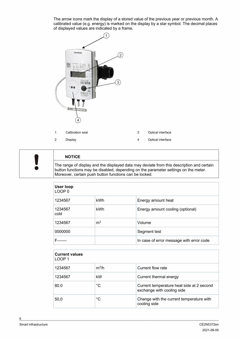
The arrow icons mark the display of a stored value of the previous year or previous month. Acalibrated value (e.g. energy) is marked on the display by a star symbol. The decimal placesof displayed values are indicated by a frame.
1 Calibration seal 3 Optical interface
2 Display 4 Optical interface
NOTICE
The range of display and the displayed data may deviate from this description and certainbutton functions may be disabled, depending on the parameter settings on the meter.Moreover, certain push button functions can be locked.
User loopLOOP 0
1234567 kWh Energy amount heat
1234567cold
kWh Energy amount cooling (optional)
1234567 m3 Volume
0000000 Segment test
F------- In case of error message with error code
Current valuesLOOP 1
1234567 m3/h Current flow rate
1234567 kW Current thermal energy
80.0 °C Current temperature heat side at 2 secondexchange with cooling side
50,0 °C Change with the current temperature withcooling side
2
3
4
1

7
Smart Infrastructure CE2N5372en
2021-08-09
21.0 K Temperature difference
P hot Mounting location (Here: Heat side, can bechanged; optional)
Bd 1234 h Runtime totalizer
Fd 123 h Error time
Pd 1234 h Time with flow rate
Monthly valuesLOOP 2
01.06.2011 Monthly date (due date) saving day
1234567 kWh Monthly value (due date) energy amountheat
1234567cold
kWh Monthly value (due date) energy amountcooling (optional)
1234567 m3 Monthly value (due date) volume on set day
Fd 123 h Missing time on set day
3,123 m3/h Maximum flow rate on set day, at 2-secondintervals with date stamp
03.02.10
279,4 kW Maximum output at 2-second intervals
03.02.10
93.7 °C Maximum output heat side at 2-secondintervals with date stamp
03.02.10
64,8 °C Maximum output cooling side at 2-secondintervals with date stamp
03.02.10
General / CommunicationLOOP 3
1234567 Device number, 7 digits
OMS RF standard (M-bus RF only)
Unbind Meter not connected (M-bus RF only)
Bind Meter connected (M-bus RF only)
MbuS Interface (only for M-bus)
127A Primary address (only for M-bus)
0000000A Secondary address (only for M-bus)
01.01 Due date (yearly set day)

8
Smart Infrastructure CE2N5372en
2021-08-09
01.--.-- Monthly value (monthly set day)
I 5-00 FW Firmware version
CrC 1234 CRC code, part requiring calibration
OtherLOOP 4
17.11.11 Current date [DD.MM.YY]
10.38.57 Current time of day [hh.mm.ss]
------- C Code entry for test/parameter operation
Error codesThe meter continuously performs self-diagnostics, allowing it to detect and display a numberof mounting or device errors.
FL nEG Wrong direction of flow
DIFF nEG Negative temperature differential
F0 Flow cannot be measured
F1 Break in sensor heat side
F2 Break in sensor cold side
F3 Electronics for temperature assessmentdefective
F4 Battery empty, power supply problem
F5 Short circuit sensor, heat side
F6 Short circuit sensor, cold side
F7 Disruption of internal memory operation
F8 F1, F2, F3, F5 or F6 persist longer than 8hoursDetection of tamperingNo further measurements are made
F9 Error in the electronics
NOTICE
Manually reset message F8 in configuration mode or using the service software. All othererror messages are deleted automatically as soon as the error is eliminated.
Previous year’s valuesThe electronic unit stores the meter readings for energy, volume, missing time, and flowmeasuring time as well as the current maximum values of flow rate, power, temperature heatand cold side with their date stamps on a yearly set day.The set day for previous year values can be parameterized.

9
Smart Infrastructure CE2N5372en
2021-08-09
Monthly valuesThe electronic unit stores the meter readings for energy, volume, missing time, and flowmeasuring time as well as the monthly maximum values of flow rate, power, temperatureheat and cold side with their date stamp for up to 24 months on the set day of each month.The set day for previous monthly values can be parameterized.In addition, a second programmable monthly set day is available for 24 months – the day onwhich energy and volume are stored.
Standard parametersThe UH50.. comes programmed as follows:● Set day [TT.MM]: 01.01
Data telegram for mobile data acquisition on WSM5xx-FE and WSN5xx-FEThe following data is factory set to acquire data (send interval 120 seconds at a battery life of11 years):● Device time● Current energy amount● Current energy amount for incorrect installation / in the cooling registers● Previous year value storage time● Prev. year value energy● Current energy amount for incorrect installation / in the cooling register● 1st previous month storage day● 1st previous month energy amount● 1st previous month energy amount for incorrect installation / in the cooling register● Error time● Error bits
Type summary
Cooling energy meter WSB.. is available upon request.
Heat meters WSM and combined heat/cold meters WSN..
The types of meters listed below are equipped as follows:
Mounting location In return
Rated pressure PN 16
Length of control cable 1.5 m
Sensor mounting Return sensor, integrated in the flowmeasuring section
Sensor type Pt500, Ø 5.2 mm, length = 45 mm
Temperature sensor cable length 1.5 m
Approval EN 1434, class 2MID 2004/22/EG
Display kWh
10
Smart Infrastructure CE2N5372en
2021-08-09
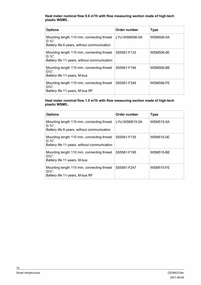
Heat meter nominal flow 0.6 m3/h with flow measuring section made of high-techplastic WSM5..
Options Order number Type
Mounting length 110 mm, connecting threadG ¾",Battery life 6-years, without communication
LYU:WSM506-0A WSM506-0A
Mounting length 110 mm, connecting threadG ¾",Battery life 11-years, without communication
S55561-F133 WSM506-0E
Mounting length 110 mm, connecting threadG¾",Battery life 11-years, M-bus
S55561-F194 WSM506-BE
Mounting length 110 mm, connecting threadG¾",Battery life 11-years, M-bus RF
S55561-F246 WSM506-FE
Heat meter nominal flow 1.5 m3/h with flow measuring section made of high-techplastic WSM5..
Options Order number Type
Mounting length 110 mm, connecting threadG ¾",Battery life 6-years, without communication
LYU:WSM515-0A WSM515-0A
Mounting length 110 mm, connecting threadG ¾",Battery life 11-years, without communication
S55561-F135 WSM515-0E
Mounting length 110 mm, connecting threadG¾",Battery life 11-years, M-bus
S55561-F195 WSM515-BE
Mounting length 110 mm, connecting threadG¾",Battery life 11-years, M-bus RF
S55561-F247 WSM515-FE

11
Smart Infrastructure CE2N5372en
2021-08-09
Heat meter nominal flow 2.5 m3/h with flow measuring section made of high-techplastic WSM5..
Options Order number Type
Mounting length 130 mm, connecting threadG¾",Battery life 6-years, without communication
LYU:WSM525-0A WSM525-0A
Mounting length 130 mm, connecting threadG¾",Battery life 11-years, without communication
S55561-F137 WSM525-0E
Mounting length 130 mm, connecting threadG1",Battery life 11-years, M-bus
S55561-F196 WSM525-BE
Mounting length 130 mm, connecting threadG1",Battery life 11-years, M-bus RF
S55561-F248 WSM525-FE
Heat meter with brass flow measuring section WSM6..
Options Order number Type
Nominal flow 0.6 m3/hMounting length 110 mm, connecting threadG ¾",Battery life 11-years, M-bus
S55561-F249 WSM606-BE
Nominal 1.5 m3/hMounting length 110 mm, connecting threadG ¾",Battery life 11-years, M-bus
S55561-F250 WSM615-BE
Nominal 2.5 m3/hMounting length 130 mm, connecting threadG¾",Battery life 11-years, M-bus
S55561-F251 WSM625-BE
Heat/cooling energy meter nominal flow 0.6 m3/h with flow measuring section made ofhigh-tech plastic WSN5..
Options Order number Type
Mounting length 110 mm, connecting threadG ¾",Battery life 11-years, M-bus
S55561-F278 WSN506-BE
Mounting length 110 mm, connecting threadG ¾",Battery life 11-years, M-bus RF
S55561-F281 WSN506-FE

12
Smart Infrastructure CE2N5372en
2021-08-09
Heat/cooling energy meter nominal flow 1.5 m3/h with flow measuring section made ofhigh-tech plastic WSN5..
Options Order number Type
Mounting length 110 mm, connecting threadG ¾",Battery life 11-years, M-bus
S55561-F279 WSN515-BE
Mounting length 110 mm, connecting threadG ¾",Battery life 11-years, M-bus RF
S55561-F282 WSN515-FE
Heat/cooling energy meter nominal flow 2.5 m3/h with flow measuring section made ofhigh-tech plastic WSN5..
Options Order number Type
Mounting length 130 mm, connecting threadG¾",Battery life 11-years, M-bus
S55561-F280 WSN525-BE
Mounting length 130 mm, connecting threadG¾",Battery life 11-years, M-bus RF
S55561-F283 WSN525-FE
Combined heat/cooling energy meters with brass flow measuring section WSN6..
Options Order number Type
Nominal flow 0.6 m3/hMounting length 110 mm, connecting threadG ¾",Battery life 11-years, M-bus
S55561-F266 WSN606-BE
Nominal 1.5 m3/hMounting length 110 mm, connecting threadG ¾",Battery life 11-years, M-bus
S55561-F267 WSN615-BE
Nominal 2.5 m3/hMounting length 130 mm, connecting threadG¾",Battery life 11-years, M-bus
S55561-F268 WSN625-BE
AccessoriesMounting accessories only for meters with high-tech plastic flow measuring sections:
Accessories for WS.5..
Component Order number Type
Flat seal G¾" LYU:9060951 9060951
Flat seal G1" LYU:9060952 9060952

13
Smart Infrastructure CE2N5372en
2021-08-09
Mounting accessories only for meters with brass flow measuring sections:
Accessories for WS.6..
Component Order number Type
Sealing disk for thread G¾" LYU:9060944002 9060944002
Sealing disk for thread G1" LYU:9060944003 9060944003
Mounting set for sensor Ø 5.2x45 mm,consisting off:- 1 sensor fitting DS M10x1 mm, brass- 2 O-rings- 1 grooved pin
LYU:WZT-FA WZT-FA
Mounting accessories for both compact meter types:
Accessories for WS.5../WS.6..
Component Order number Type
Mounting set 110 mm, consisting of:2x ball valve Rp ¾" with union nut G ¾"(WZT-K34-34)1x ball valve Rp ¾" with connection for thedirect installation of temperature sensorsM10x1 mm (WZT-K34)1x spacer 110 mm (WZM-G110)2x flat seals
LYU:WZT-MS110 WZT-MS110
Mounting 130 mm, consisting of:2x ball valve Rp 1" with union nut G1" (WZT-K1-1)1x ball valve Rp 1" with connection for thedirect installation of temperature sensorsM10x1 mm (WZT-K1)1x spacer 130 mm (WZM-G130)2x flat seals
LYU:WZT-MS130 WZT-MS130
Mounting kit G ¾", consisting of:2x threaded connection G ¾" x R ½"2x cap nuts G ¾"
S55563-F124 WZM-E34
Mounting kit 1", consisting of:2x threaded connection G 1" x R ¾"2x cap nuts G 1"
S55563-F123 WZM-E1
Adapter piece 110 mm G ¾" to 130 mm G¾":1x extension G¾ B" to G¾ B"1x gasket G ¾"
LYU:WZM-V130 WZM-V130
Adapter piece 110 mm G ¾" to 130 mmG 1": 2x extension G ¾ B" to G 1 B"2x gaskets G 1"
LYU:WZM-V130.G1 WZM-V130.G1

14
Smart Infrastructure CE2N5372en
2021-08-09
Adapter piece 110 mm G ¾" to 165 mm G¾":1x extension G¾ B" to G¾ B"1x gasket G ¾"
LYU:WZM-VE165 WZM-VE165
Adapter piece 110 mm G ¾" to 190 mm G1":2x extension G ¾ B" to G 1 B"2x gaskets G 1"
LYU:WZM-V190 WZM-V190
Sealing disk, copper, for protection pocket G½" or adapter WZT-A12, Ø 27.9/ 21.2 mm x1.5 mm
LYU:9060948 9060948
Ball valve R ½" with union nut G ¾" LYU:WZT-K12-34 WZT-K12-34
Ball valve R ¾ " with union nut G ¾" LYU:WZT-K34-34 WZT-K34-34
Ball valve R ¾ " with union nut G 1" LYU:WZT-K34-1 WZT-K34-1
Ball valve R 1" with union nut G 1" LYU:WZT-K1-1 WZT-K1-1
Ball valve R ½" to install a DS sensor M10 x1 mm, length = 28 mm, max. 130°C, PN 25
S55563-F104 WZT-K12
Ball valve R ¾" to install a DS sensor M10 x1 mm, length = 28 mm, max. 130°C, PN 25
S55563-F120 WZT-K34
Ball valve R 1" to install a DS sensor M10 x 1mm, length = 28 mm, max. 130°C, PN 25
S55563-F119 WZT-K1
Adapter G 3/8 B" with threaded holeM10x1 mm for sensor, including gasket G3/8" made of copper
LYU:WZT-A38 WZT-A38
Adapter G ½ B" with threaded hole M10x1mm for sensor, including gasket G ½" madeof copper
S55563-F116 WZT-A12
Adapter G ¾ B" with threaded holeM10x1 mm for sensor, including gasket G3/4" made of copper
LYU:WZT-A34 WZT-A34
Protection pocket G ½ B" made of brass,Ø 5.2x35 mm for temperature sensor Ø5.2x45 mm, including gasket G ½", copper
S55563-F103 WZT-M35
Protection pocket G ½ B made of brass,Ø 5.2x50 mm for temperature sensor Ø5.2x45 mm, including gasket G ½", copper
LYU:WZT-M50 WZT-M50
Protection pocket G ½ B made of stainlesssteel, Ø 5.2x50 mm for temperature sensorØ 5.2x45 mm, including gasket G ½", copper
LYU:WZT-S43V WZT-S43V
Adapter kit, consisting of:- 1x plastic adapter Ø 5.2x45 mm- 1 mounting aid for sensor Ø 5.2x45 mm- 2 O-rings
LYU:9956230 9956230
Spacer G ¾", length 110 mm,incl. 2 gaskets
LYU:WZM-G110 WZM-G110

15
Smart Infrastructure CE2N5372en
2021-08-09
Spacer G 1", length 130 mm,incl. 2 gaskets
LYU:WZM-G130 WZM-G130
Welding sleeve with threaded hole fortemperature sensor DS M10x1 mm
S55563-F121 WZT-G10
Welding sleeve G½", 45° to pipe axis, withthreaded hole G½"
LYU:WZT-G12 LYU:WZT-G12
Welding sleeve G ½", 90° to pipe axis, withthreaded hole G ½"
LYU:WZT-GLG LYU:WZT-GLG
Self-lock seal with sealing wire LYU:9956186001 9956186001
10 wall adapters for mounting the electronicunit on the wall, including 2 screws and 2dowels
LYU:T23-WA10 T23-WA10
Programming accessories
Component Order number Type
Optical read head with USB plug for PCinterface
LYU:WZR-OP-USB WZR-OP-USB
Readout and configuration software:- UltraAssist
Download -
OrderingPlease specify the quantity, order number, and type when ordering.
Scope of deliveryThe ultrasonic meter is supplied complete with Mounting Instructions in different languages,an adapter kit, 2 gaskets and a seal.
LanguagesThe Installation Instructions are supplied in the following languages:Bulgarian, Chinese, Czech, Dutch, English, French, German, Greek, Hungarian, Italian,Norwegian, Polish, Russian, Serbo-Croatian, Slovakian, Slovenian, Spanish and Turkish.
Product documentation
Related documents such as environmental declarations, CE declarations, etc., can be down-loaded at the following Internet address:http://siemens.com/bt/download
16
Smart Infrastructure CE2N5372en
2021-08-09
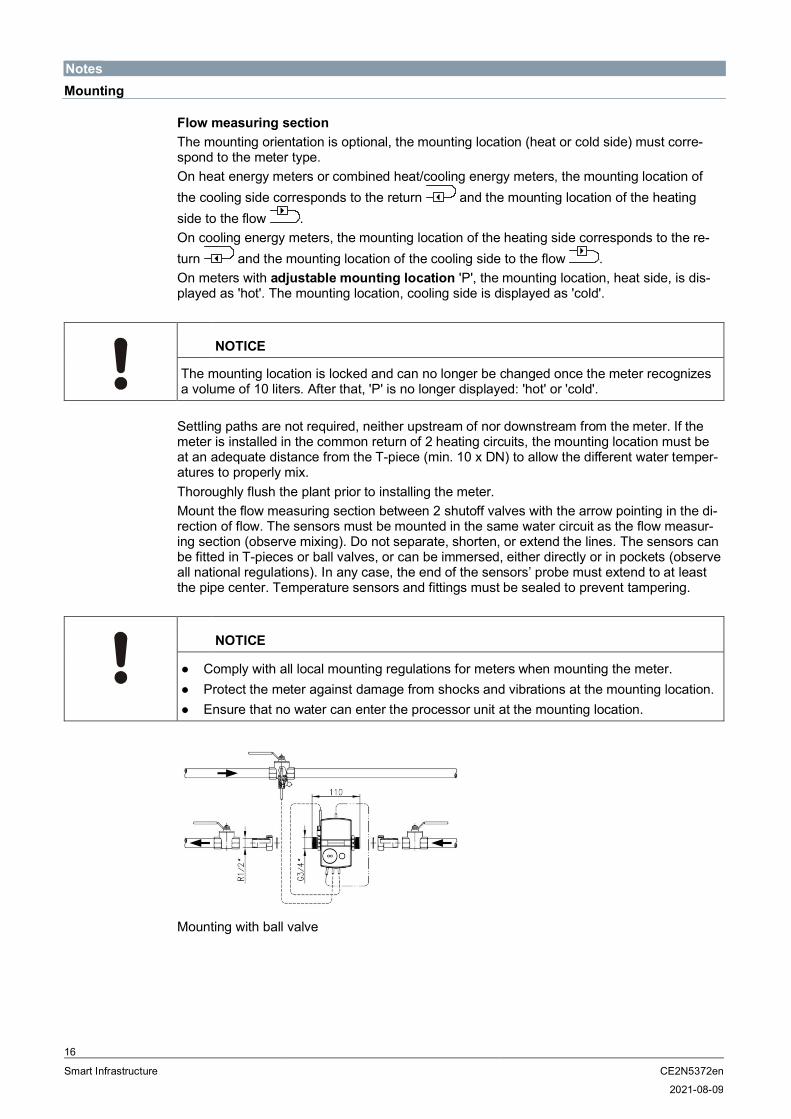
NotesMounting
Flow measuring sectionThe mounting orientation is optional, the mounting location (heat or cold side) must corre-spond to the meter type.On heat energy meters or combined heat/cooling energy meters, the mounting location ofthe cooling side corresponds to the return and the mounting location of the heatingside to the flow .On cooling energy meters, the mounting location of the heating side corresponds to the re-turn and the mounting location of the cooling side to the flow .On meters with adjustable mounting location 'P', the mounting location, heat side, is dis-played as 'hot'. The mounting location, cooling side is displayed as 'cold'.
NOTICE
The mounting location is locked and can no longer be changed once the meter recognizesa volume of 10 liters. After that, 'P' is no longer displayed: 'hot' or 'cold'.
Settling paths are not required, neither upstream of nor downstream from the meter. If themeter is installed in the common return of 2 heating circuits, the mounting location must beat an adequate distance from the T-piece (min. 10 x DN) to allow the different water temper-atures to properly mix.Thoroughly flush the plant prior to installing the meter.Mount the flow measuring section between 2 shutoff valves with the arrow pointing in the di-rection of flow. The sensors must be mounted in the same water circuit as the flow measur-ing section (observe mixing). Do not separate, shorten, or extend the lines. The sensors canbe fitted in T-pieces or ball valves, or can be immersed, either directly or in pockets (observeall national regulations). In any case, the end of the sensors’ probe must extend to at leastthe pipe center. Temperature sensors and fittings must be sealed to prevent tampering.
NOTICE
● Comply with all local mounting regulations for meters when mounting the meter.● Protect the meter against damage from shocks and vibrations at the mounting location.● Ensure that no water can enter the processor unit at the mounting location.
Mounting with ball valve

17
Smart Infrastructure CE2N5372en
2021-08-09
Required position for the cooling energy meterTo avoid the formation of condensation on cooling energy or combined heat/cooling energymeters, make sure the cover on the measuring tube points to the side or downward. Installthe protection pockets so that the temperature sensor is horizontal or vertical, pointing down.Mount the processor unit away from the flow measuring section (e.g. on the wall). Make surethat condensation cannot run along the connected lines, entering the processor unit (forminga loop downward).Permissible mounting position when metering cooling energy:
1 Transducer cover (only applies to WS.6..)
Processor unitThe ambient temperature of the processor unit cannot exceed 55 °C. Avoid direct sunlight.Ensure that no water can enter the processor unit at the mounting location.For water temperatures between 10 °C and 90 °C, the processor can be secured to the flowmeasuring section.For water temperatures above 90 °C and/or below 10 °C, mount the processor unit on thewall (split mounting).The adapter plate on the wall or the flow measuring section can be aligned as needed to en-sure ease of reading. To remove the electronic unit, turn the housing by 45° to the side andlift.To fit the processor unit to the wall, remove it from the flow measuring section and screw theadapter plate to the wall and slide the processor unit to the adapter base, snapping intoplace.
NOTICE
WS.5..: The adapter plate cannot be removed. The wall adapter must be ordered separate-ly as an accessory.WS.6..: The adapter plate can be removed from the flow measuring section.
1

18
Smart Infrastructure CE2N5372en
2021-08-09
Wall mounting Wall adapter (view from above)
Wall adapter (side view) Maximal screw head height(if using the wall bracket)
MaintenanceThe meters are maintenance-free.Observe all national calibration regulations.
Disposal
The device is considered an electronic device for disposal in terms of theEuropean Directive and may not be disposed of as domestic waste.● Use only designated channels for disposing the devices.● Comply with all local and currently applicable laws and regulations.● Dispose of empty batteries in designated collection points.
Warranty serviceThe application-related technical data is only guaranteed together with the products men-tioned in this data sheet. Siemens rejects any and all warranties in the event that third-partyproducts are used.

19
Smart Infrastructure CE2N5372en
2021-08-09
Technical data
Processor unit
Power supply
Battery type Lithium battery (cannot be replaced)
Battery voltage 3.6 V
Battery life 6 or 11 years
Function data
Measuring range 0…180 °C
Range of temperature differential ΔΘ 3 ... 80 K
Temperature response threshold 0.2 K.
Thermal coefficient Shifting compensated
Temperature-measuring error without sensor (0.5 + ΔΘmin./ ΔΘ) %,Max. 1.5% at ΔΘ = 3 K
Temperature sensor
Sensing element Pt500
Type Ø 5.2 x 45 mm
Flow measuring section
Function data
Temperature range(national approvals may differ)● Heating
● Cooling
5…90 °C (Plastic flow measuring section)5…105 °C (Brass flow measuring section)5…50 °C (Observe national approvals)
Maximum temperature tmax °C 90
Rated pressure MPa 1.6 (PN 16)
Nominal flow qp m3/h 0.6 1.5 2.5
Meterological class 1:100 1:100 1:100
Maximum flow qs m3/h 1.2 3 5
Minimum flow qi l/h 6 15 25
Response threshold l/h 1.2 3 5

20
Smart Infrastructure CE2N5372en
2021-08-09
Pressure drop at qp● Mounting length 110 mm
Δp● Mounting length 130 mm
Δp
mbarmbar
75 1) / 150 2)
---135 1) / 150 2)
135 1) / 160 2)---
165 1) / 200 2)
Flow rate at Δp = 1 bar, Kv,m3/h
2.2 1) / 1.5 2) 4.11) / 3.9 2) 6.81) / 5.6 2)
Mounting position Any
1) Plastic flow measuring section2) Brass flow measuring section
Communication
Optical interface● Basic design● Protocol
Similar to EN 62056-21Per EN 13757-2 / -3
M-bus wired interface Optional
● Voltage Vmax. 50 V
● Power consumption 1 M-bus load
● Addressing Primary or secondary
● Baud rate 300 or 2400 baud
● Max. permissible reading frequency 1x per minute
● Protocol As per EN 13757-2/-3, EN 1434-3
● Connection cable length and cross sec-tion
1.5 m, 2x AWG24/0.2 mm2
M-bus RF interface Optional
● Transmission frequency 868.95 MHz (868.90 … 869.00 MHz)
● Transmitter power Min. 3.16 mW (5 dBm) to max. 25 mW (13.9dBm)
● Power supply Max. 3 AA batteries
● Send interval– Mobile data acquisition– Stationary data acquisition– User defined telegrams
20…34 s15 minutes.12…900 s (depending on telegram length)
Protocol Per EN 13757-4
Cable length, control cable 1.5 m

21
Smart Infrastructure CE2N5372en
2021-08-09
Housing type
Protection class III
Degree of protection● Processor unit● Flow measuring section
IP54WS.5..: IP65WSM6..: IP54WSB6../WSN6..: IP65
Ambient conditions
OperationEN 60721-3-3
TransportationEN 60721-3-2
StorageEN 60721-3-1
Climatic conditions Class A Class A Class A
Temperature 5...55 °C -20...60 °C -20...60 °C
Humidity <93 % r.h. at25°°C (non-condensing)
<93 % r.h. at25°°C (non-condensing)
<93 % r.h. at25°°C (non-condensing)
Mechanical conditions Class M1 Class M1 Class M1
Max. altitude Min. 700 hPa, corresponding to max.2000 m above sea level
Standards and guidelines
Product standards DIN EN 1434-x (heat meters)
EU conformity (CE) CE2T5372xx *)
RCM Conformity CE2T5372en_C1 *)
Environmental compatibility
The product environmental declaration CE2E5372en *) contains data on environmentallycompatible product design and assessments (RoHS compliance, material composition,packaging, environmental benefit, and disposal).
Dimensions (W x H x D)
Processor unit 116 x 71 x 32 mm
Flow measuring section See "Dimensions”
Housing material
CoverBottom sectionBattery compartment
ABSPC-GF10PC clear

22
Smart Infrastructure CE2N5372en
2021-08-09
Housing colors
CoverBottom section
RAL 9006RAL 9002
Weight
Device packed complete with inserts WSM506..: 0.52 kgWSM515..: 0.52 kgWSM525..: 0.56 kgWS.606..: 0.80 kgWS.615..: 0.76 kgWS.625..: 0.84 kg
*) Documents can be downloaded at http://www.siemens.com/bt/download.
23
Smart Infrastructure CE2N5372en
2021-08-09
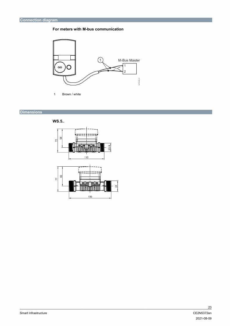
Connection diagram
For meters with M-bus communication
1 Brown / white
Dimensions
WS.5..

WS.6..
Dimensions in mm
Issued bySiemens Switzerland LtdSmart InfrastructureGlobal HeadquartersTheilerstrasse 1aCH-6300 Zug+41 58 724 2424www.siemens.com/buildingtechnologies
© Siemens Switzerland Ltd, 2012Technical specifications and availability subject to change without notice.
Document ID CE2N5372en
Edition 2021-08-09