Embed Size (px)
Citation preview
**************************************************************************USACE / NAVFAC / AFCEC / NASA UFGS- 33 61 13. 19 ( Febr uar y 2016) - - - - - - - - - - - - - - - - - - - - - - - - - - - - - - - -Pr epar i ng Act i v i t y: USACE Super sedi ng UFGS- 33 60 01 ( Apr i l 2008)
UNI FI ED FACI LI TI ES GUI DE SPECI FI CATI ONS
Ref er ences ar e i n agr eement wi t h UMRL dat ed Januar y 2018**************************************************************************
SECTI ON TABLE OF CONTENTS
DI VI SI ON 33 - UTI LI TI ES
SECTI ON 33 61 13. 19
VALVES, PI PI NG, AND EQUI PMENT I N VALVE MANHOLES
02/16
PART 1 GENERAL
1. 1 REFERENCES 1. 2 SUBMI TTALS 1. 3 QUALI TY ASSURANCE 1. 3. 1 Det ai l Dr awi ngs 1. 3. 2 I nsul at ed Sect i ons 1. 4 DELI VERY, STORAGE, AND HANDLI NG
PART 2 PRODUCTS
2. 1 STANDARD PRODUCTS 2. 2 NAMEPLATES 2. 3 ASBESTOS PROHI BI TI ON 2. 4 ELECTRI CAL WORK 2. 5 PI PI NG AND FI TTI NGS 2. 5. 1 Gener al Requi r ement s 2. 5. 2 St eel Pi pe 2. 5. 2. 1 Ni ppl es 2. 5. 2. 2 Pi pe Thr eads 2. 5. 3 Fi t t i ngs 2. 5. 3. 1 Wel ded Fi t t i ngs 2. 5. 3. 2 Uni ons 2. 5. 3. 3 Bal l Val ves 2. 5. 4 I nsul at i ng Fl anges and Di el ect r i c Wat er ways 2. 5. 4. 1 I nsul at i ng Fl anges 2. 5. 4. 2 Di el ect r i c Wat er ways 2. 5. 4. 3 Gasket s Non- I nsul at i ng 2. 6 VALVES 2. 6. 1 St eel Val ves 2. 6. 2 Br onze Val ves 2. 6. 2. 1 Gl obe, Gat e, and Angl e Val ves 2. 6. 2. 2 Check Val ves 2. 6. 3 Packi ng 2. 7 STEAM TRAPS 2. 7. 1 Bucket Tr aps
SECTI ON 33 61 13. 19 Page 1

2. 7. 2 Ther most at i c Tr aps 2. 8 STRAI NERS 2. 9 PRESSURE GAUGES 2. 10 DI AL THERMOMETERS 2. 11 COATI NGS 2. 12 I NSULATI ON AND JACKETI NG 2. 12. 1 Gener al Pr ovi s i ons 2. 12. 2 I nsul at i on 2. 12. 3 Al umi num Jacket s 2. 12. 4 Bands 2. 12. 5 I nsul at i on f or Fl anges, Uni ons, Val ves, and Fi t t i ngs 2. 12. 6 Vapor Bar r i er Coat i ng 2. 12. 7 Fi ni shi ng Cement 2. 12. 8 Gl ass Tape 2. 12. 9 Pl ai n Weave, Unt r eat ed 2. 12. 10 Kni t t ed, Unt r eat ed 2. 12. 11 Di st or t i on Requi r ement s 2. 12. 12 Open- Weave Tape 2. 13 SUMP PUMPS AND DRAI NERS 2. 13. 1 Sump Pumps 2. 13. 1. 1 Mot or s 2. 13. 1. 2 Cont r ol s 2. 13. 2 Hi gh Level Al ar m I ndi cat or 2. 13. 3 Dr ai ner s 2. 14 CONCRETE VALVE MANHOLES AND ACCESSORI ES 2. 14. 1 Wal l and Fl oor Const r uct i on 2. 14. 2 Manhol e Suppor t ed Cover ( s) 2. 14. 3 Rai sed Fr ame Cover ( s) 2. 14. 4 Concr et e Cover 2. 14. 5 Ladder s 2. 14. 6 Pi pe Sl eeves 2. 14. 6. 1 Pi pe Sl eeves Thr ough Val ve Manhol e Cover 2. 14. 6. 2 Pi pe Sl eeves f or Condui t Penet r at i ons 2. 14. 7 Pi pe Suppor t s 2. 15 EXPANSI ON JOI NTS 2. 15. 1 Gui ded Sl i p Tube 2. 15. 2 Fl exi bl e Bal l 2. 15. 3 Bel l ows- Type 2. 16 MI SCELLANEOUS METAL
PART 3 EXECUTI ON
3. 1 EXAMI NATI ON 3. 2 SI TE WORK 3. 2. 1 Excavat i on, Tr enchi ng, and Backf i l l i ng 3. 2. 2 El ect r i c Wor k 3. 2. 3 Pai nt i ng 3. 3 PI PI NG 3. 3. 1 Gener al 3. 3. 2 Wel ded Joi nt s 3. 3. 3 Fl anged and Thr eaded Joi nt s 3. 3. 3. 1 Fl anged Joi nt s 3. 3. 3. 2 Thr eaded Joi nt s 3. 3. 4 Reduci ng Fi t t i ngs 3. 3. 4. 1 Hor i zont al Wat er Heat i ng Li nes 3. 3. 4. 2 Hor i zont al St eam Li nes 3. 3. 5 Br anch Connect i ons 3. 3. 6 Pi pe Suppor t s i n Val ve Manhol es 3. 4 WELDI NG
SECTI ON 33 61 13. 19 Page 2

3. 5 COATI NGS 3. 6 I NSULATI ON 3. 6. 1 I nst al l at i on 3. 6. 2 I nsul at i on on Pi pes Passi ng Thr ough Sl eeves 3. 6. 3 Cover i ng of I nsul at i on i n Val ve Manhol es 3. 6. 4 I nsul at i on of Pi pi ng Accessor i es i n Val ve Manhol es 3. 6. 5 I nsul at i on Seal i ng f or Chi l l ed Wat er Syst ems 3. 6. 6 I nsul at i on Thi ckness 3. 7 VALVE MANHOLES AND ACCESSORI ES 3. 7. 1 Pi pi ng and Equi pment i n Val ve Manhol es 3. 7. 2 Sump Pumps I nst al l at i on 3. 8 TESTS
- - End of Sect i on Tabl e of Cont ent s - -
SECTI ON 33 61 13. 19 Page 3

**************************************************************************USACE / NAVFAC / AFCEC / NASA UFGS- 33 61 13. 19 ( Febr uar y 2016) - - - - - - - - - - - - - - - - - - - - - - - - - - - - - - - -Pr epar i ng Act i v i t y: USACE Super sedi ng UFGS- 33 60 01 ( Apr i l 2008)
UNI FI ED FACI LI TI ES GUI DE SPECI FI CATI ONS
Ref er ences ar e i n agr eement wi t h UMRL dat ed Januar y 2018**************************************************************************
SECTI ON 33 61 13. 19
VALVES, PI PI NG, AND EQUI PMENT I N VALVE MANHOLES02/16
**************************************************************************NOTE: Thi s gui de speci f i cat i on cover s t he r equi r ement s f or val ves, pi pi ng and equi pment i n val ve manhol es t hat f or m a par t of an under gr ound heat di st r i but i on syst em.
Adher e t o UFC 1- 300- 02 Uni f i ed Faci l i t i es Gui de Speci f i cat i ons ( UFGS) For mat St andar d when edi t i ng t hi s gui de speci f i cat i on or pr epar i ng new pr oj ect speci f i cat i on sect i ons. Edi t t hi s gui de speci f i cat i on f or pr oj ect speci f i c r equi r ement s by addi ng, del et i ng, or r evi s i ng t ext . For br acket ed i t ems, choose appl i cabl e i t em( s) or i nser t appr opr i at e i nf or mat i on.
Remove i nf or mat i on and r equi r ement s not r equi r ed i n r espect i ve pr oj ect , whet her or not br acket s ar e present.
Comment s, suggest i ons and r ecommended changes f or t hi s gui de speci f i cat i on ar e wel come and shoul d be submi t t ed as a Cr i t er i a Change Request ( CCR) .
**************************************************************************
PART 1 GENERAL
**************************************************************************NOTE: Desi gn manual UFC 3- 430- 01FA HEATI NG AND COOLI NG DI STRI BUTI ON SYSTEMS cont ai ns i nf or mat i on t hat wi l l assi st t he desi gner . Do not al l ow chi l l ed wat er l i nes or ot her pl ast i c pi pi ng t o be r out ed t hr ough manhol es wher e hi gh t emper at ur e pi pi ng syst ems ( above 110 degr ees C 230 degr ees F) ar e installed.
Pr ovi de t he f ol l owi ng i nf or mat i on on t he cont r act dr awi ngs: ( 1) val ve manhol e di mensi ons, ( 2) l ocat i on of al l val ve manhol es, ( 3) s i zes of t he pi pe i n t he val ve manhol es, ( 4) l ocat i on of al l val ves i n t he val ve manhol es, ( 5) t hi ckness of t he i nsul at i on on t he pi pe, ( 6) val ve manhol e det ai l s ,
SECTI ON 33 61 13. 19 Page 4
( 7) f i nal el evat i ons of t he val ve manhol es, ( 8) val ve manhol e cover det ai l s i ncl udi ng manway access det ai l s , ( 9) how val ve manhol es ar e dr ai ned and vent ed, ( 10) sump pump pi pi ng det ai l s , ( 11) val ve manhol e equi pment di mensi ons and det ai l s , ( 12) sump pump capaci t y, ( 13) el ect r i cal wi r i ng det ai l s f or t he equi pment ( dedi cat ed ser vi ce f or sump pump) , ( 14) st eam dr i p t r ap l ocat i ons wi t h access and capaci t i es, ( 15) st eam mai n dr i p l eg s i zes.
Thi s gui de speci f i cat i on i s t o be i ncl uded as a par t of a cont r act whi ch i ncl udes Sect i ons 33 61 13. 13 PREFABRI CATED UNDERGROUND HYDRONI C ENERGY DI STRI BUTI ON or 33 57 00 BULK FUEL RECEI VI NG/ DI SPENSI NG EQUI PMENT; 33 61 13 PRE- ENGI NEERED UNDERGROUND HEAT DI STRI BUTI ON SYSTEM or 33 63 16 EXTERI OR SHALLOW TRENCH STEAM DI STRI BUTI ON; 33 63 13. 19 CONCRETE TRENCH HYDRONI C AND STEAM ENERGY DI STRI BUTI ON or 33 63 13EXTERI OR UNDERGROUND STEAM DI STRI BUTI ON SYSTEM. I ncl ude t he f ol l owi ng Sect i ons as par t of t hi s cont r act : 31 00 00 EARTHWORK; 33 71 01 OVERHEAD TRANSMI SSI ON AND DI STRI BUTI ON; 33 71 02 UNDERGROUND ELECTRI CAL DI STRI BUTI ON; 03 15 00. 00 10 CONCRETE ACCESSORI ES; Sect i on [ 03 30 00. 00 10 CAST- I N- PLACE CONCRETE] [03 30 00 CAST- I N- PLACE CONCRETE] ; 05 05 23. 16 STRUCTURAL WELDI NG; 05 50 13 MI SCELLANEOUS METAL FABRI CATI ONS; 07 13 53 ELASTOMERI C SHEET WATERPROOFI NG; 09 90 00 PAI NTS AND COATI NGS; 40 05 13. 96 or 40 17 26. 00 20 WELDI NG PROCESS PI PI NG; 26 20 00 I NTERI OR DI STRI BUTI ON SYSTEM or 26 51 00 I NTERI OR LI GHTI NG; and ot her s as appl i cabl e t o t he pr oj ect .
**************************************************************************
1. 1 REFERENCES
**************************************************************************NOTE: Thi s par agr aph i s used t o l i s t t he publ i cat i ons c i t ed i n t he t ext of t he gui de speci f i cat i on. The publ i cat i ons ar e r ef er r ed t o i n t he t ext by basi c desi gnat i on onl y and l i s t ed i n t hi s par agr aph by or gani zat i on, desi gnat i on, dat e, and t i t l e.
Use t he Ref er ence Wi zar d' s Check Ref er ence f eat ur e when you add a Ref er ence I dent i f i er ( RI D) out s i de of t he Sect i on' s Ref er ence Ar t i c l e t o aut omat i cal l y pl ace t he r ef er ence i n t he Ref er ence Ar t i c l e. Al so use t he Ref er ence Wi zar d' s Check Ref er ence f eat ur e t o updat e t he i ssue dat es.
Ref er ences not used i n t he t ext wi l l aut omat i cal l y be del et ed f r om t hi s sect i on of t he pr oj ect speci f i cat i on when you choose t o r econci l e r ef er ences i n t he publ i sh pr i nt pr ocess.
**************************************************************************
The publ i cat i ons l i s t ed bel ow f or m a par t of t hi s speci f i cat i on t o t he
SECTI ON 33 61 13. 19 Page 5
ext ent r ef er enced. The publ i cat i ons ar e r ef er r ed t o wi t hi n t he t ext by t he basi c desi gnat i on onl y.
ALUMI NUM ASSOCI ATI ON ( AA)
AA H35. 1/ 35. 1M ( 2017) Amer i can Nat i onal St andar d Al l oy and Temper Desi gnat i on Syst ems f or Al umi num
ASME I NTERNATI ONAL ( ASME)
ASME B1. 20. 1 ( 2013) Pi pe Thr eads, Gener al Pur pose ( I nch)
ASME B1. 20. 2M ( 2006; R 2011) Pi pe Thr eads, 60 Deg. Gener al Pur pose ( Met r i c)
ASME B16. 11 ( 2016) For ged Fi t t i ngs, Socket - Wel di ng and Threaded
ASME B16. 20 ( 2012; R 2017) Met al l i c Gasket s f or Pi pe Flanges
ASME B16. 21 ( 2011) Nonmet al l i c Fl at Gasket s f or Pi pe Flanges
ASME B16. 3 ( 2011) Mal l eabl e I r on Thr eaded Fi t t i ngs, Cl asses 150 and 300
ASME B16. 34 ( 2017) Val ves - Fl anged, Thr eaded and Wel di ng End
ASME B16. 5 ( 2017) Pi pe Fl anges and Fl anged Fi t t i ngs NPS 1/ 2 Thr ough NPS 24 Met r i c/ I nch St andar d
ASME B16. 9 ( 2012) St andar d f or Fact or y- Made Wr ought St eel But t wel di ng Fi t t i ngs
ASME B31. 1 ( 2016; Er r at a 2016) Power Pi pi ng
ASME B40. 100 ( 2013) Pr essur e Gauges and Gauge Attachments
ASME BPVC SEC I X ( 2010) BPVC Sect i on I X- Wel di ng and Br azi ng Qualifications
ASTM I NTERNATI ONAL ( ASTM)
ASTM A106/ A106M ( 2014) St andar d Speci f i cat i on f or Seaml ess Car bon St eel Pi pe f or Hi gh- Temper at ur e Service
ASTM A123/ A123M ( 2017) St andar d Speci f i cat i on f or Zi nc ( Hot - Di p Gal vani zed) Coat i ngs on I r on and St eel Pr oduct s
ASTM A193/ A193M ( 2016) St andar d Speci f i cat i on f or Al l oy- St eel and St ai nl ess St eel Bol t i ng Mat er i al s f or Hi gh- Temper at ur e Ser vi ce and Ot her Speci al Pur pose Appl i cat i ons
SECTI ON 33 61 13. 19 Page 6

ASTM A194/ A194M ( 2017a) St andar d Speci f i cat i on f or Car bon St eel , Al l oy St eel , and St ai nl ess St eel Nut s f or Bol t s f or Hi gh- Pr essur e or Hi gh- Temper at ur e Ser vi ce, or Bot h
ASTM A53/ A53M ( 2012) St andar d Speci f i cat i on f or Pi pe, St eel , Bl ack and Hot - Di pped, Zi nc- Coat ed, Wel ded and Seaml ess
ASTM A733 ( 2013) St andar d Speci f i cat i on f or Wel ded and Seaml ess Car bon St eel and Aust eni t i c St ai nl ess St eel Pi pe Ni ppl es
ASTM B209 ( 2014) St andar d Speci f i cat i on f or Al umi num and Al umi num- Al l oy Sheet and Pl at e
ASTM B209M ( 2014) St andar d Speci f i cat i on f or Al umi num and Al umi num- Al l oy Sheet and Pl at e ( Met r i c)
ASTM C449 ( 2007; R 2013) St andar d Speci f i cat i on f or Mi ner al Fi ber Hydr aul i c- Set t i ng Ther mal I nsul at i ng and Fi ni shi ng Cement
ASTM C533 ( 2017) St andar d Speci f i cat i on f or Cal c i um Si l i cat e Bl ock and Pi pe Ther mal I nsul at i on
ASTM C547 ( 2017) St andar d Speci f i cat i on f or Mi ner al Fi ber Pi pe I nsul at i on
ASTM C552 ( 2017) St andar d Speci f i cat i on f or Cel l ul ar Gl ass Ther mal I nsul at i on
ASTM C647 ( 2008; R 2013) Pr oper t i es and Test s of Mast i cs and Coat i ng Fi ni shes f or Ther mal Insulation
ASTM D2822/ D2822M ( 2005; R 2011; E 2011) St andar d Speci f i cat i on f or Asphal t Roof Cement , Asbestos-Containing
ASTM D3278 ( 1996; R 2011) Fl ash Poi nt of Li qui ds by Smal l Scal e Cl osed- Cup Appar at us
ASTM D3359 ( 2017) St andar d Test Met hods f or Rat i ng Adhesi on by Tape Test
ASTM E84 ( 2017) St andar d Test Met hod f or Sur f ace Bur ni ng Char act er i st i cs of Bui l di ng Materials
ASTM E96/ E96M ( 2016) St andar d Test Met hods f or Wat er Vapor Tr ansmi ssi on of Mat er i al s
ASTM F1139 ( 1988; R 2015) St eam Tr aps and Dr ai ns
MANUFACTURERS STANDARDI ZATI ON SOCI ETY OF THE VALVE AND FI TTI NGS I NDUSTRY ( MSS)
MSS SP- 110 ( 2010) Bal l Val ves Thr eaded,
SECTI ON 33 61 13. 19 Page 7

Socket - Wel di ng, Sol der Joi nt , Gr ooved and Fl ar ed Ends
MSS SP- 25 ( 2013) St andar d Mar ki ng Syst em f or Val ves, Fi t t i ngs, Fl anges and Uni ons
MSS SP- 45 ( 2003; R 2008) Bypass and Dr ai n Connect i ons
MSS SP- 58 ( 1993; Reaf f i r med 2010) Pi pe Hanger s and Suppor t s - Mat er i al s, Desi gn and Manuf act ur e, Sel ect i on, Appl i cat i on, and Installation
MSS SP- 72 ( 2010a) Bal l Val ves wi t h Fl anged or But t - Wel di ng Ends f or Gener al Ser vi ce
MSS SP- 80 ( 2013) Br onze Gat e, Gl obe, Angl e and Check Valves
MSS SP- 83 ( 2014) Cl ass 3000 St eel Pi pe Uni ons Socket Wel di ng and Thr eaded
NATI ONAL FI RE PROTECTI ON ASSOCI ATI ON ( NFPA)
NFPA 70 ( 2017; ERTA 1- 2 2017; TI A 17- 1; TI A 17- 2; TI A 17- 3; TI A 17- 4; TI A 17- 5; TI A 17- 6; TI A 17- 7; TI A 17- 8; TI A 17- 9; TI A 17- 10; TI A 17- 11; TI A 17- 12; TI A 17- 13; TI A 17- 14) Nat i onal El ect r i cal Code
NFPA 90A ( 2018) St andar d f or t he I nst al l at i on of Ai r Condi t i oni ng and Vent i l at i ng Syst ems
SOCI ETY FOR PROTECTI VE COATI NGS ( SSPC)
SSPC Pai nt 16 ( 2006; R 2015; E 2015) Coal Tar Epoxy- Pol yami de Bl ack ( or Dar k Red) Pai nt
SSPC Pai nt 29 ( 2002; E 2004) Zi nc Dust Sacr i f i c i al Pr i mer , Per f or mance- Based
SSPC SP 10/ NACE No. 2 ( 2007) Near - Whi t e Bl ast Cl eani ng
UNDERWRI TERS LABORATORI ES ( UL)
UL 723 ( 2008; Repr i nt Aug 2013) Test f or Sur f ace Bur ni ng Char act er i st i cs of Bui l di ng Materials
1. 2 SUBMITTALS
**************************************************************************NOTE: Revi ew submi t t al descr i pt i on ( SD) def i ni t i ons i n Sect i on 01 33 00 SUBMI TTAL PROCEDURES and edi t t he f ol l owi ng l i s t t o r ef l ect onl y t he submi t t al s r equi r ed f or t he pr oj ect .
The Gui de Speci f i cat i on t echni cal edi t or s have desi gnat ed t hose i t ems t hat r equi r e Gover nment
SECTI ON 33 61 13. 19 Page 8

appr oval , due t o t hei r compl exi t y or cr i t i cal i t y , wi t h a " G. " Gener al l y, ot her submi t t al i t ems can be r evi ewed by t he Cont r act or ' s Qual i t y Cont r ol Syst em. Onl y add a “ G” t o an i t em, i f t he submi t t al i s suf f i c i ent l y i mpor t ant or compl ex i n cont ext of t he pr oj ect .
For submi t t al s r equi r i ng Gover nment appr oval on Ar my pr oj ect s, a code of up t o t hr ee char act er s wi t hi n t he submi t t al t ags may be used f ol l owi ng t he " G" desi gnat i on t o i ndi cat e t he appr ovi ng aut hor i t y. Codes f or Ar my pr oj ect s usi ng t he Resi dent Management Syst em ( RMS) ar e: " AE" f or Ar chi t ect - Engi neer ; " DO" f or Di st r i c t Of f i ce ( Engi neer i ng Di v i s i on or ot her or gani zat i on i n t he Di st r i c t Of f i ce) ; " AO" f or Ar ea Of f i ce; " RO" f or Resi dent Of f i ce; and " PO" f or Pr oj ect Of f i ce. Codes f ol l owi ng t he " G" t ypi cal l y ar e not used f or Navy, Ai r For ce, and NASA pr oj ect s.
Use t he " S" c l assi f i cat i on onl y i n SD- 11 Cl oseout Submi t t al s. The " S" f ol l owi ng a submi t t al i t em i ndi cat es t hat t he submi t t al i s r equi r ed f or t he Sust ai nabi l i t y eNot ebook t o f ul f i l l f eder al l y mandat ed sust ai nabl e r equi r ement s i n accor dance wi t h Sect i on 01 33 29 SUSTAI NABI LI TY REPORTI NG.
Choose t he f i r st br acket ed i t em f or Navy, Ai r For ce and NASA pr oj ect s, or choose t he second br acket ed i t em f or Ar my pr oj ect s.
**************************************************************************
Gover nment appr oval i s r equi r ed f or submi t t al s wi t h a " G" desi gnat i on; submi t t al s not havi ng a " G" desi gnat i on ar e f or [ Cont r act or Qual i t y Cont r ol appr oval . ] [ i nf or mat i on onl y. When used, a desi gnat i on f ol l owi ng t he " G" desi gnat i on i dent i f i es t he of f i ce t hat wi l l r evi ew t he submi t t al f or t he Gover nment . ] Submi t t al s wi t h an " S" ar e f or i ncl usi on i n t he Sust ai nabi l i t y eNot ebook, i n conf or mance t o Sect i on 01 33 29 SUSTAI NABI LI TY REPORTI NG. Submi t t he f ol l owi ng i n accor dance wi t h Sect i on 01 33 00 SUBMI TTAL PROCEDURES:
SD- 02 Shop Dr awi ngs
Det ai l Dr awi ngs; G[ , [ _____] ]
SD- 03 Pr oduct Dat a
Suppor t of t he Equi pment
Pi pi ng and Fi t t i ngs
Valves
I nsul at i ng Fl anges
Insulation
Sump Pumps and Dr ai ner s
SECTI ON 33 61 13. 19 Page 9

Expansi on Joi nt s
SD- 04 Sampl es
I nsul at ed Sect i ons; G[ , [ _____] ]
SD- 10 Oper at i on and Mai nt enance Dat a
Val ve Manhol es and Accessor i es; G[ , [ _____] ]
Dat a Package 2; G[ , [ _____] ]
1. 3 QUALI TY ASSURANCE
1. 3. 1 Det ai l Dr awi ngs
Submi t det ai l dr awi ngs [ _____] days af t er not i ce t o pr oceed f or val ve manhol es and t he pi pi ng and equi pment i n t he val ve manhol es, such as st eam t r aps, val ves, sump pumps, pr essur e gauges, t her momet er s and i nsul at i on, i ncl udi ng a compl et e l i s t of equi pment and mat er i al s, manuf act ur er ' s descr i pt i ve and t echni cal l i t er at ur e, per f or mance char t s and cur ves, cat al og cut s, i nst al l at i on i nst r uct i ons, and compl et e wi r i ng and schemat i c di agr ams. Show on t he dr awi ngs pi pe anchor s and gui des, and l ayout and anchor age of equi pment and appur t enances i n val ve manhol es, and equi pment r el at i onshi p t o ot her par t s of t he wor k i ncl udi ng c l ear ances f or mai nt enance and oper at i on.
1. 3. 2 I nsul at ed Sect i ons
Submi t sampl e sect i ons, [ _____] days af t er not i ce t o pr oceed, f or i nsul at i on of pi pe, el bow, t ee, val ve, suppor t poi nt , and t er mi nat i ng poi nt s. Af t er appr oval of mat er i al s and pr i or t o i nsul at i on of pi pi ng, pr epar e a di spl ay of i nsul at ed sect i ons showi ng compl i ance wi t h speci f i cat i ons and showi ng f ast eni ng, seal i ng, j acket i ng, st r aps, wat er pr oof i ng, suppor t s, hanger s, anchor s, and saddl es. Di spl ay appr oved di spl ay sampl e sect i ons at t he j obsi t e dur i ng t he const r uct i on per i od unt i l no l onger needed by Cont r act i ng Of f i cer , t hen r emoved.
1. 4 DELI VERY, STORAGE, AND HANDLI NG
Pr ot ect al l mat er i al s and equi pment del i ver ed and pl aced i n st or age f r om t he weat her , excessi ve humi di t y, and excessi ve t emper at ur e var i at i on; di r t , dust , or ot her cont ami nant s.
PART 2 PRODUCTS
2. 1 STANDARD PRODUCTS
Pr ovi de mat er i al s and equi pment whi ch ar e t he st andar d pr oduct s of a manuf act ur er r egul ar l y engaged i n t he manuf act ur e of such pr oduct s and t hat essent i al l y dupl i cat e i t ems t hat have been i n sat i sf act or y use f or at l east 2 year s pr i or t o bi d openi ng.
Equi pment i t ems must be suppor t ed by ser vi ce or gani zat i ons. Submi t a cer t i f i ed l i s t of qual i f i ed per manent ser vi ce or gani zat i ons f or suppor t of t he equi pment whi ch i ncl udes t hei r addr esses and qual i f i cat i ons. These ser vi ce or gani zat i ons must be r easonabl y conveni ent t o t he equi pment i nst al l at i on and abl e t o r ender sat i sf act or y ser vi ce t o t he equi pment on a r egul ar and emer gency basi s dur i ng t he war r ant y per i od of t he cont r act .
SECTI ON 33 61 13. 19 Page 10

2. 2 NAMEPLATES
Suppl y each maj or i t em of equi pment such as sump pump, mot or , st eam t r ap, and pr essur e r educi ng val ve wi t h t he manuf act ur er ' s name, addr ess, t ype or st y l e, model or ser i al number , and cat al og number on a pl at e secur ed t o t he i t em of equi pment .
2. 3 ASBESTOS PROHI BI TI ON
Asbest os and asbest os- cont ai ni ng pr oduct s ar e not al l owed.
2. 4 ELECTRI CAL WORK
Pr ovi de mot or s, manual or aut omat i c mot or cont r ol equi pment , and pr ot ect i ve or s i gnal devi ces r equi r ed f or t he oper at i on speci f i ed under t hi s sect i on i n accor dance wi t h NFPA 70 and Sect i on 33 71 02 UNDERGROUND ELECTRI CAL DISTRIBUTION.
2. 5 PI PI NG AND FI TTI NGS
2. 5. 1 Gener al Requi r ement s
Pr ovi de pi pi ng, f i t t i ngs and pi pi ng accessor i es i nsi de t he val ve manhol es sui t abl e f or t he wor ki ng pr essur e and t emper at ur e r equi r ement s of t he syst em conf or mi ng t o ASME B31. 1. To t he gr eat est ext ent possi bl e, mat ch t he pi pi ng and f i t t i ngs i nsi de t he val ve manhol es t o t he pi pi ng and f i t t i ngs l ocat ed on t he out s i de of t he val ve manhol e. Pr ovi de st eel pi pi ng i n val ve manhol es wi t h j oi nt s wel ded except t hat j oi nt s 19 mm 3/ 4 i nch and smal l er may be t hr eaded. When t hr eaded j oi nt s ar e used on Hi gh Temper at ur e Wat er Syst ems, seal wel d ( cont i nuous f i l l et wel d) t he i nt er f ace ar ea wher e t he pi pe t hr eads meet t he t hr eaded f i t t i ngs t o pr ecl ude any wat er l eakage. Do not at t ach suppor t s, anchor s, or st ays t o any pi pi ng syst em i n pl aces wher e ei t her t he i nst al l at i on of or t he movement of t he pi pe and i t s cont ent s wi l l cause damage t o t he const r uct i on.
2. 5. 2 St eel Pi pe
Pr ovi de bl ack st eel , seaml ess or el ect r i c- r esi st ance wel ded, conf or mi ng t o t he r equi r ement s of ASTM A53/ A53M, Gr ade B or ASTM A106/ A106M, Gr ade B. Pr ovi de schedul e 40 t ype f or pi pe up t o and i ncl udi ng 250 mm 10 i nches i n di amet er . Pr ovi de 10 mm 0. 375 i nch nomi nal wal l t hi ckness f or pi pe 300 mm 12 i nches i n di amet er and gr eat er . Pr ovi de schedul e 80 t ype f or gauge pi pi ng [ , condensat e pi pi ng, ] [ dr i p pi pi ng, ] [ sump pump di schar ge] and pi pi ng 19 mm 3/ 4 i nch i n di amet er and smal l er .
2. 5. 2. 1 Nipples
Pr ovi de ni ppl es t hat conf or m t o ASTM A733 as r equi r ed t o mat ch adj acent piping.
2. 5. 2. 2 Pi pe Thr eads
Pr ovi de pi pe t hr eads t hat conf or m t o ASME B1. 20. 2MASME B1. 20. 1. Use pi pe t hr eads onl y on pi pe 19 mm 3/ 4 i nch or smal l er .
2. 5. 3 Fittings
Pr ovi de f i t t i ngs, val ves, f l anges and uni ons wi t h t he manuf act ur er ' s
SECTI ON 33 61 13. 19 Page 11

t r ademar k af f i xed i n accor dance wi t h MSS SP- 25 so as t o per manent l y i dent i f y t he manuf act ur er .
2. 5. 3. 1 Wel ded Fi t t i ngs
Pr ovi de wel ded f i t t i ngs t o mat ch connect i ng pi pes wi t h but t wel ded f i t t i ngs, conf or mi ng t o ASME B16. 9, and socket wel ded f i t t i ngs, conf or mi ng to ASME B16. 11.
2. 5. 3. 2 Unions
Pr ovi de uni ons t hat conf or m t o MSS SP- 83 as r equi r ed t o mat ch adj acent piping.
2. 5. 3. 3 Bal l Val ves
Pr ovi de bal l val ves havi ng f l anged or but t wel ded end connect i ons conf or mi ng to MSS SP- 72; pr ovi de bal l val ves havi ng t hr eaded end connect i ons conf or mi ng t o MSS SP- 110.
2. 5. 4 I nsul at i ng Fl anges and Di el ect r i c Wat er ways
**************************************************************************NOTE: El ect r i cal l y i nsul at i ng f l anges or di el ect r i c wat er ways shal l be shown i n manhol es wher e pi pi ng i s connect ed t o a syst em t hat i s not cat hodi cal l y pr ot ect ed. I nsul at i ng f l anges and di el ect r i c wat er ways must be i n accessi bl e l ocat i ons, such as val ve manhol es or bui l di ngs.
**************************************************************************
2. 5. 4. 1 I nsul at i ng Fl anges
For syst ems i n whi ch cat hodi c pr ot ect i on i s used, pr ovi de i nsul at i ng f l anges or f l ange gasket k i t s i n t he val ve manhol e at t he pi pe connect i on t o or f r om t he heat di st r i but i on syst em, at t he i nt er f ace of di ssi mi l ar met al s, and when t he car r i er pi pe and appur t enances ar e suppor t ed i n such a way as t o el ect r i cal l y gr ound or al t er t he cat hodi c pr ot ect i on syst em vol t ages or cur r ent s. Pr ovi de a k i t t hat consi st s of f l anges, a f l ange gasket , nut s and bol t s, bol t s l eeves, and one i nsul at i ng washer and one st eel washer f or bot h ends of each bol t . Pr ovi de manuf act ur er cer t i f i ed gasket k i t s capabl e of el ect r i cal l y i sol at i ng t he pi pe at t he [ _____] kPa psi g pr essur e and [ _____] degr ees C F t emper at ur e of t he heat i ng medi um at t he poi nt of appl i cat i on. Submi t evi dence of sat i sf act or y i nst al l at i ons oper at i ng not l ess t han 2 year s, i n accor dance wi t h par agr aph SUBMI TTALS, bef or e mat er i al s ar e del i ver ed. Ensur e t hat t hese k i t s ar e pr ovi ded and pr oper l y i nst al l ed accor di ng t o manuf act ur er ' s publ i shed i nst r uct i ons. Pr ovi de bol t s t or qued t o t he cor r ect t i ght ness and i n t he cor r ect bol t pat t er n as r ecommended by t he manuf act ur er ' s publ i shed i nst r uct i ons. Pr ovi de st eel f l anges t hat conf or m t o ASME B16. 5 Cl ass [ 150] [ and] [ or ] [ 300] and t hat mat ch val ves or f l anged f i t t i ngs on whi ch used. Pr ovi de f l at f aced st eel f l anges. Pr ovi de non- asbest os compr essed mat er i al gasket s i n accor dance wi t h ASME B16. 21. Pr ovi de bol t s t hat conf or m t o t he r equi r ement s of ASTM A193/ A193M, Gr ade B7. Pr ovi de bol t heads mar ked t o i dent i f y t he manuf act ur er and t he st andar d t o whi ch t he bol t compl i es. Ext end bol t l engt hs t o no l ess t hen 2 f ul l t hr eads beyond t he nut at t he r equi r ed t ensi on wi t h t he washer seat ed. Pr ovi de nut s t hat conf or m t o t he r equi r ement s of ASTM A194/ A194M, Gr ade 7.
SECTI ON 33 61 13. 19 Page 12

2. 5. 4. 2 Di el ect r i c Wat er ways
Pr ovi de di el ect r i c wat er ways t hat have t emper at ur e and pr essur e r at i ng equal t o or gr eat er t han t hat speci f i ed f or t he connect i ng pi pi ng and used f or j oi ni ng di ss i mi l ar met al s on 19 mm 3/ 4 i nch and smal l er t hr eaded pi pe. Pr ovi de wat er ways t hat have met al connect i ons on bot h ends sui t ed t o mat ch connect i ng pi pi ng. Pr ovi de di el ect r i c wat er ways t hat ar e i nt er nal l y l i ned wi t h an i nsul at or speci f i cal l y desi gned t o pr event cur r ent f l ow bet ween di ssi mi l ar met al s. Pr ovi de di el ect r i c f l anges t hat meet t he per f or mance r equi r ement s descr i bed her ei n f or di el ect r i c wat er ways.
2. 5. 4. 3 Gasket s Non- I nsul at i ng
Pr ovi de spi r al wound, non- asbest os gasket wi t h cent er i ng r i ng t hat conf or m to ASME B16. 20.
2. 6 VALVES
**************************************************************************NOTE: Sel ect t he appr opr i at e val ves f or t he oper at i ng t emper at ur es and pr essur es of al l syst ems i n t he pr oj ect . Del et e val ve t ypes not i ncl uded i n project.
Use not l ess t han Cl ass 150 f or up t o 862 kPa 125 psi g st eam, and not l ess t han Cl ass 300 f or 863 kPa t o 1724 kPa 126 t o 250 psi g st eam and hi gh t emper at ur e wat er . For i sol at i on and shut of f , use gat e val ves onl y. St eam pr essur e r educi ng val ves ar e not nor mal l y par t of t he syst em. I f needed, desi gner shoul d r ef er t o Sect i on 23 70 01. 00 10 CENTRAL STEAM- GENERATI NG SYSTEM, COAL- FI RED or Sect i on 23 22 26. 00 20 STEAM SYSTEM AND TERMI NAL UNI TS f or Navy j obs.
**************************************************************************
Pr ovi de val ves t hat conf or m t o t he mat er i al , f abr i cat i on, and oper at i ng r equi r ement s of ASME B31. 1, unl ess ot her wi se speci f i ed. Pr ovi de val ves sui t abl e f or t he ser vi ce t emper at ur es and pr essur es ut i l i zed. Pr ovi de val ves f or [ st eam] [ hot wat er ] t hat conf or m t o ASME B31. 1 Cl ass [ 150] [ and] [ or ] [ 300] , as sui t abl e f or ser vi ce t emper at ur es and pr essur es ut i l i zed. [ Pr ovi de val ves f or condensat e ser vi ces t hat conf or m t o ASME B31. 1 Cl ass 150. ] Val ves 19 mm 3/ 4 i nch and smal l er may be br onze wher e seal wel di ng i s not r equi r ed. Pr ovi de val ves 150 mm 6 i nches and l ar ger wi t h a 25 mm 1 i nch mi ni mum gat e or gl obe bypass val ve s i zed i n conf or mance wi t h MSS SP- 45.
2. 6. 1 St eel Val ves
Pr ovi de st eel gl obe, gat e, angl e, and check val ves t hat conf or m t o t he r equi r ement s of ASME B16. 34 and ASME B31. 1 f or t he ser vi ce t emper at ur es and pr essur es ut i l i zed. Pr ovi de gat e val ves 65 mm 2- 1/ 2 i nches and smal l er wi t h a r i s i ng st em. Pr ovi de gat e val ves 80 mm 3 i nches and l ar ger wi t h an out s i de scr ew and yoke.
2. 6. 2 Br onze Val ves
2. 6. 2. 1 Gl obe, Gat e, and Angl e Val ves
Pr ovi de br onze gl obe, gat e, and angl e val ves t hat conf or m t o MSS SP- 80,
SECTI ON 33 61 13. 19 Page 13
uni on bonnet t ype.
2. 6. 2. 2 Check Val ves
Pr ovi de br onze check val ves t hat conf or m t o MSS SP- 80.
2. 6. 3 Packing
Pr ovi de asbest os f r ee val ve packi ng. Pr ovi de di e- f or med, r i ng t ype speci f i cal l y desi gnat ed val ve st em packi ng sui t abl e f or ser vi ce t emper at ur es and pr essur es ut i l i zed. Pr ovi de pol yt et r af l uor oet hyl ene packi ng t hat has a wi t h mi ni mum 50 per cent gr aphi t e f i l ament . Pr ovi de val ves 40 mm 1- 1/ 2 i nches and smal l er wi t h f our or f i ve packi ng r i ngs and pr ovi de val ves 50 mm 2 i nches and l ar ger wi t h at l east s i x packi ng r i ngs. Spi r al or cont i nuous packi ng wi l l not be accept abl e. Pr ovi de a met al i nser t havi ng pr oper c l ear ance ar ound t he val ve st em at t he bot t om of t he st uf f i ng box and act i ng as a base f or t he packi ng mat er i al . Pr ovi de one pi ece const r uct i on wi t h pr ovi s i ons f or not l ess t han t wo bol t s f or packi ng adj ust ment , wi t h a l i ner of noncor r osi ve mat er i al f or packi ng gl ands.
2. 7 STEAM TRAPS
**************************************************************************NOTE: The f ol l owi ng par agr aphs ar e appl i cabl e t o st eam syst ems onl y. Onl y t hese t wo t ypes wi l l be used. Del et e t hese par agr aphs when t he di st r i but i on syst em i s not a st eam syst em.
A schedul e of st eam t r ap sel ect i on wi l l be shown on t he dr awi ngs. Tr ap capaci t y ( kg per second ( pounds per hour ) dur i ng nor mal oper at i on, pr essur e dr op ( kPa ( psi ) , and pr essur e r at i ng ( kPa ( psi ) of each t r ap wi l l be i ncl uded i n t hi s schedul e. Al so, show on t he dr awi ngs a vent val ve or t est val ve connect i on downst r eam of t r aps f or t est of t r ap oper at i on, a st r ai ner ahead of t r aps, a uni on, a check val ve i n t he out l et pi pi ng, and shut - of f val ves on bot h s i des of t r ap f or t r ap changeout . A means of bypassi ng t he t r ap shal l be pr ovi ded f or syst em war m- up.
**************************************************************************
Pr ovi de f ai l open t r aps wi t h t r ap bodi es sui t abl e f or a wor ki ng pr essur e of not l ess t han 1. 5 t i mes t he st eam suppl y pr essur e, but not l ess t han 1379 kPa 200 psi .
2. 7. 1 Bucket Tr aps
Pr ovi de i nver t ed- bucket t ype bucket t r aps wi t h aut omat i c ai r di schar ge conf or mi ng t o ASTM F1139.
2. 7. 2 Ther most at i c Tr aps
**************************************************************************NOTE: Speci f y t her most at i c t r aps wher e t he t r ap l ocat i on i s subj ect t o f r eezi ng.
**************************************************************************
Pr ovi de t her most at i c t r aps t hat have a bi met al l i c el ement wi t h aut omat i c ai r di schar ge conf or mi ng t o ASTM F1139.
SECTI ON 33 61 13. 19 Page 14

[ 2. 8 STRAINERS
**************************************************************************NOTE: Del et e t hi s par agr aph f or hi gh t emper at ur e wat er syst ems.
**************************************************************************
Pr ovi de basket or y- t ype st r ai ner s wi t h connect i ons t he same si ze as t he pi pe l i nes i n whi ch t he connect i ons ar e i nst al l ed. Pr ovi de heavy and dur abl e st r ai ner bodi es, of cast st eel , wi t h bot t oms dr i l l ed and pl ugged sui t abl e f or ser vi ce t emper at ur es and pr essur es ut i l i zed. Pr ovi de each st r ai ner body wi t h ar r ows cl ear l y cast on t he s i des t o i ndi cat e t he di r ect i on of f l ow. Pr ovi de each st r ai ner wi t h an easi l y r emovabl e cover and sedi ment basket . Pr ovi de each st r ai ner body or bot t om openi ng wi t h a ni ppl e and gat e val ve f or bl owdown. Pr ovi de 0. 6350 mm 0. 025 i nch t hi ck st ai nl ess st eel , monel or sheet br ass st r ai ner basket wi t h smal l per f or at i ons of suf f i c i ent number t o pr ovi de a net f r ee ar ea at l east 2. 5 t i mes t hat of t he ent er i ng pi pe. Pr ovi de cast st eel bodi es and st ai nl ess or Monel basket s f or hi gh t emper at ur e hot wat er syst ems.
] 2. 9 PRESSURE GAUGES
Pr ovi de pr essur e gauges t hat conf or m t o ASME B40. 100 wi t h a mi ni mum di al s i ze of 110 mm 4- 1/ 4 i nches. Pr ovi de each gauge wi t h a t hr ot t l i ng t ype needl e val ve or a pul sat i on dampener and shut - of f val ve.
2. 10 DI AL THERMOMETERS
Pr ovi de di al t ype t her momet er s 90 mm 3- 1/ 2 i nches i n di amet er wi t h st ai nl ess st eel case, r emot e- t ype bul b or di r ect - t ype bul b as r equi r ed. Pr ovi de t her momet er s t hat have an accur acy of pl us or mi nus 1 degr ee C 2 degr ees F. Pr ovi de t her momet er wel l s of t he separ abl e socket t ype f or each t her momet er wi t h a di r ect - t ype bul b. Pr ovi de t her momet er wi t h a whi t e f ace wi t h bl ack di gi t s gr aduat ed i n 1 degr ee C 2 degr ees F i ncr ement s.
2. 11 COATINGS
Coat st eel manhol e pi pi ng wi t h an or gani c z i nc under coat t hat conf or ms t o SSPC Pai nt 29 Type I I f ol l owed by a t her mal bar r i er coat i ng havi ng a manuf act ur er ’ s document ed mi ni mum t her mal conduct i v i t y of 0. 100 W/ m• K 0. 058 Bt u/ hr • f t • ° F. Pr ovi de t he under coat and t her mal bar r i er coat i ng wi t h a cont i nuous use ser vi ce t emper at ur e r at i ng t hat exceeds t he nomi nal syst em oper at i ng t emper at ur e by a mi ni mum of 28 degr ees C 50 degr ees F.
2. 12 I NSULATI ON AND JACKETI NG
**************************************************************************NOTE: Al l pi pi ng, val ves and f i t t i ngs f or st eam, hot wat er and dual t emper at ur e heat di st r i but i on syst ems i n val ve manhol es r equi r e i nsul at i on f or t he pr ot ect i on of oper at i ng and mai nt enance per sonnel as wel l as f or t he conser vat i on of ener gy; whet her or not t o i nsul at e chi l l ed wat er l i nes, val ves, and f i t t i ngs i n t he manhol es can be det er mi ned by t he necessi t y t o pr event condensat i on on t he pi pi ng and ener gy conser vat i on.
The ener gy savi ngs wi l l var y wi t h t he ambi ent
SECTI ON 33 61 13. 19 Page 15

t emper at ur e but wi l l be a f act or i n war m cl i mat es. Ther e may be some i sol at ed cases wher e t he chi l l ed wat er di st r i but i on pi pes ent er i ng t he manhol e ar e not i nsul at ed; t her ef or e, t he pi pi ng i n t he manhol e woul d not nor mal l y be i nsul at ed unl ess condensat i on f r om t he ai r f or mi ng on t he chi l l ed wat er pi pes causes a pr obl em.
**************************************************************************
2. 12. 1 Gener al Pr ovi s i ons
I nsul at e pi pi ng, f i t t i ngs, val ves, et c. , i n t he val ve manhol es. Pr ovi de i nsul at i on pr emol ded, pr ecut or j ob f abr i cat ed t o f i t and be r emovabl e and r eusabl e. Pr ovi de t hi ckness of i nsul at i on i n accor dance wi t h Tabl es 1 and 2. Pr ovi de i nsul at i on j acket s f or al l pi pe and f i t t i ng i nsul at i on. Pr ovi de i nsul at i on t hat conf or ms t o EPA r equi r ement s i n accor dance wi t h Sect i on 01 33 29 SUSTAI NABI LI TY REPORTI NG.
2. 12. 2 Insulation
**************************************************************************NOTE: The i nsul at i ons al l owed i n t hi s par agr aph have passed a 96 hour boi l i ng t est whi ch i ndi cat es t hat sat i sf act or y per f or mance i s expect ed.
**************************************************************************
Pr ovi de pi pi ng, f i t t i ngs, and val ves wi t h mol ded cal c i um si l i cat e i nsul at i on conf or mi ng t o ASTM C533, Type I , or mol ded mi ner al f i ber i nsul at i on conf or mi ng t o ASTM C547, Cl ass 2, or cel l ul ar gl ass i nsul at i on conf or mi ng t o ASTM C552. Do not use l ami nat ed const r uct i on unl ess t he t hi ckness exceeds 100 mm 4 i nches. I nsul at i on manuf act ur er s appr oved f or use ar e:
a. Del t a, avai l abl e f r om Rockwool i n Leeds, Al abama.
b. MPT- PC and MPT- PF, avai l abl e f r om Mi ner al Pr oduct s of Texas i n Houst on, TX.
c. Ther mo- 12, Super Cal t emp, avai l abl e f r om Johns Manvi l l e i n Denver , Colorado.
d. Foamgl ass ( cel l ul ar gl ass) , avai l abl e f r om Pi t t sbur gh Cor ni ng Corporation.
2. 12. 3 Al umi num Jacket s
**************************************************************************NOTE: Vapor bar r i er r equi r ement s ar e onl y t o be i ncl uded f or chi l l ed wat er syst ems.
**************************************************************************
Pr ovi de al umi num j acket s of smoot h sheet , 0. 4064 mm 0. 016 i nch nomi nal t hi ckness, t hat conf or m t o t he r equi r ement s of ASTM B209M ASTM B209, Type 3003, 3105, or 5005. [ Suppl y al umi num j acket s t hat have a f act or y i nst al l ed moi st ur e bar r i er t hat consi st s of at l east 18. 1 kg 40 pound kr af t paper coat ed on one si de wi t h a 0. 025 mm 1 mi l t hi ck pol yet hyl ene f i l m. Pr ovi De a j acket wi t h t he moi st ur e bar r i er adher ed t o t he j acket over t he ent i r e ar ea of t he i nsul at i on- si de sur f ace. ]
SECTI ON 33 61 13. 19 Page 16

2. 12. 4 Bands
Pr ovi de bands f or al umi num j acket 10 mm 3/ 8 i nch wi de and 32 gauge t hi ckness made of al umi num or anneal ed st ai nl ess st eel . Pr ovi de bands f or i nsul at i on 13 mm 1/ 2 i nch wi de and 32 gauge t hi ckness made of anneal ed st ai nl ess st eel .
2. 12. 5 I nsul at i on f or Fl anges, Uni ons, Val ves, and Fi t t i ngs
I nsul at e f l anges, uni ons, val ves, and f i t t i ngs wi t h pr emol ded, pr ef abr i cat ed, or f i el d f abr i cat ed segment s of i nsul at i on of t he same mat er i al and t hi ckness as t he manhol e pi pe i nsul at i on. Pr ovi de i nsul at i on wi t h essent i al l y t he same t her mal char act er i st i cs and t hi ckness as t he adj oi ni ng pi pi ng.
2. 12. 6 Vapor Bar r i er Coat i ng
Pr ovi de i nsul at i on wi t h a vapor bar r i er coat i ng t hat i s wat er r esi st ant , appr opr i at el y sel ect ed f or ei t her out door or i ndoor ser vi ce, col or ed whi t e, and has a wat er vapor per meance of t he compound not exceedi ng 0. 05 per m as det er mi ned accor di ng t o Pr ocedur e B of ASTM E96/ E96M. Pr ovi de a coat i ng t hat i s t he nonf l ammabl e, f i r e r esi st ant t ype conf or mi ng t o ASTM E84, NFPA 90A and UL 723 and has a f l ash poi nt not l ess t han 26. 7 degr ees C 80 degr ees F as det er mi ned i n accor dance wi t h ASTM D3278. Pr ovi de a coat i ng t hat conf or ms t o ASTM C647; excl udi ng t he pr evi ous f i r e r es i st ant requirements.
2. 12. 7 Fi ni shi ng Cement
Pr ovi de mi ner al f i ber hydr aul i c- set t i ng t her mal i nsul at i ng cement t hat conf or ms wi t h ASTM C449.
2. 12. 8 Gl ass Tape
Pr ovi de t ape t hat conf or ms t o t he r equi r ement s of UL 723 and ASTM E84.
2. 12. 9 Pl ai n Weave, Unt r eat ed
Pr ovi de wi t h t he ends i nt er l ocked wi t h t he pi cks t o ensur e no r avel i ng of t he t ape edges. Pr ovi de t ape t hat i s an aver age wei ght of 196. 7 pl us or mi nus 10 per cent gr ams per squar e met er 5. 8 pl us or mi nus 10 per cent ounces per squar e yar d, and aver age t hi ckness of 0. 1778 pl us or mi nus 0. 0254 mm 0. 007 pl us or mi nus 0. 001 i nches. Pr ovi de wi t h war p ends or wal es of 17 pl us or mi nus 1 per cent i met er 42 pl us or mi nus 2 per i nch or f i l l i ng pi cks or cour ses of 13 pl us or mi nus 1 per cent i met er 32 pl us or mi nus 2 per i nch; a mi ni mum br eaki ng st r engt h of 2679 gr ams per mm 150 pounds per i nch of wi dt h; and af t er heat i ng t o 482 degr ees C 900 degr ees F f or 2 hour s, a mi ni mum br eaki ng st r engt h of 714 gr ams per mm 40 pounds per i nch of wi dt h.
2. 12. 10 Kni t t ed, Unt r eat ed
Pr ovi de wi t h t he wal es i nt er l ocked wi t h t he cour ses t o ensur e no r avel i ng of t he t ape edges. Pr ovi de t ape t hat i s an aver age wei ght of 153 pl us or mi nus 10 per cent gr ams per squar e met er 4. 5 pl us or mi nus 10 per cent ounces per squar e yar d; aver age t hi ckness of 0. 1778 pl us or mi nus 0. 0254 mm 0. 007 pl us or mi nus 0. 001 i nches; and war p ends/ wal es of 6 pl us or mi nus per 1 cent i met er 16 pl us or mi nus 2 per i nch. Use mat er i al wi t h mi ni mum br eaki ng st r engt h of 714 gr ams per mm 40 pounds per i nch of wi dt h and, af t er heat i ng t o 482 degr ees C 900 degr ees F f or 2 hour s, mi ni mum br eaki ng st r engt h of
SECTI ON 33 61 13. 19 Page 17

375 gr ams per mm 21 pounds per i nch of wi dt h.
2. 12. 11 Di st or t i on Requi r ement s
Di st or t i on of t he t ape when a sampl e 610 mm 24 i nches i n l engt h i s spr ead acr oss a f l at hor i zont al sur f ace and obser ved f or evi dence of di st or t i on ( such as t endency t o cur l r at her t han l i e f l at ) i s not accept abl e. The wi dt h t ol er ance i s pl us or mi nus 3 mm 1/ 8 i nch.
2. 12. 12 Open- Weave Tape
Pr ovi de open- weave t ype t ape, used f or embeddi ng bet ween coat s of adhesi ve or coat i ng mat er i al s, t hat has an aver age wei ght of [ _____] kg per squar e met er ounce per squar e yar d.
2. 13 SUMP PUMPS AND DRAI NERS
**************************************************************************NOTE: The appl i cat i on woul d be f or a submer si bl e sump pump i n a manhol e ser vi ng an under gr ound heat di st r i but i on syst em. Fl ow r ange 1. 6 L/ s 25 t o 50 gpm, head of 4. 5 t o 9 TDH 15 t o 30 TDH, f l ui d t emp of 93 degr ees C 200 deg F. When pump per f or mance i s out s i de t he f l ow, head or t emper at ur e r ange i dent i f i ed her ei n, mat er i al s of const r uct i on need t o be val i dat ed wi t h a pump suppl i er and speci f i cat i on wr i t t en wher eby mul t i pl e vendor s can meet bot h per f or mance and mat er i al const r uct i on as speci f i ed. Del et e t hi s par agr aph when posi t i ve dr ai nage of t he val ve manhol e i s pr ovi ded and sump pumps ar e not needed. Use of dupl ex sump pumps i s encour aged. Del et e t ext i n br acket s i f a s i ngl e sump pump i s specified.
Pr ovi de one or t wo sump pumps i n val ve manhol es. Uni t s shoul d di schar ge by bur i ed pi pi ng t o t he near est st or m sewer i f possi bl e. Wher e not economi cal t o di schar ge t o a st or m sewer , pumps ar e t o di schar ge above gr ade. Pl an di schar ge l ocat i ons car ef ul l y so wat er wi l l not be di schar ged over val ve manhol e t ops, s i dewal ks, et c. Check avai l abl e NPSH ver sus r equi r ed NPSH f or pump sel ect ed. Coor di nat e power r equi r ement s wi t h el ect r i cal desi gner and pr ovi de t el l - t al e l i ght above gr ound t o i ndi cat e sump pump f ai l ur e. Dr awi ngs wi l l show t he f ol l owi ng: ( a) a dedi cat ed c i r cui t ; ( b) l ockabl e swi t ches and ci r cui t br eaker s t hat can bot h be l ocked ON; ( c) per manent l abel s at key posi t i ons i ndi cat ed on t he dr awi ngs so t hat per sonnel can under st and t hat t he c i r cui t shoul d be l ef t ON. The l abel shal l be on a cor r osi on r esi st ant met al pl at e and shal l r ead as follows:THI S CI RCUI T SUPPLI ES POWER TO THE ELECTRI C SUMP PUMPS I N THE UNDERGROUND HEAT DI STRI BUTI ON SYSTEM. THI S CI RCUI T MUST BE ON AT ALL TI MES; OTHERWI SEEXTENSI VE DAMAGE WI LL OCCUR TO THE UNDERGROUND HEAT DI STRI BUTI ON SYSTEM AND PREMATURE FAI LURE WI LL OCCUR.
SECTI ON 33 61 13. 19 Page 18

**************************************************************************
2. 13. 1 Sump Pumps
Pr ovi de a manuf act ur er ' s st andar d commer ci al pr oduct t hat i s el ect r i cal l y dr i ven and submer si bl e, capabl e of oper at i ng whi l e compl et el y submer ged, and capabl e of r unni ng wi t hout damage when not submer ged. The pumps and mot or s must be capabl e of cont i nuousl y pumpi ng l i qui ds at a t emper at ur e of 93 degr ees C 200 degr ees F. Pr ovi de sump pumps wi t h per manent l y l ubr i cat ed bear i ngs, [ monel ] [ st ai nl ess st eel ] shaf t s, [ br onze] [ st ai nl ess st eel ] [ cast i r on] i mpel l er s, scr eened i nl et s and housi ngs of [ br onze] [ st ai nl ess st eel ] [ cast i r on] . Each sump pump must be capabl e of passi ng a 10 mm 3/ 8 i nch spher e.
2. 13. 1. 1 Motors
Pr ovi de mot or s wi t h over l oad pr ot ect i on. Pr ovi de pump[ s] t hat ar e aut omat i cal l y cont r ol l ed, usi ng cont r ol component s pr ovi ded by t he pump manuf act ur er , by a submer si bl e swi t ch assembl y wi t h pump wi r i ng and swi t ch sui t abl e f or submer si on i n 93 degr ees C 200 degr ees F l i qui ds. [ Pr ovi de dupl ex ( one on - one st andby) ar r angement wi t h aut omat i c al t er nat i ng l ead- l ag cont r ol l er . ] Pr ovi de [ cor d and pl ug] [ har dwi r ed] mot or el ect r i cal connections.
2. 13. 1. 2 Controls
Pr ovi de cont r ol s, cont r ol l er s, wat er l evel swi t ches, and el ect r i cal connect i ons sui t abl e f or ser vi ce at 100 per cent humi di t y, at 93 degr ees C 200 degr ees F t emper at ur e, and occasi onal wat er submer si on. The sump pumps aut omat i c cont r ol swi t ches must have demonst r at ed 200, 000 cycl es at 93 degr ees C 200 degr ees F and 100 per cent r el at i ve humi di t y whi l e t ot al l y submer sed i n wat er at 93 degr ees C 200 degr ees F.
2. 13. 2 Hi gh Level Al ar m I ndi cat or
Pr ovi de anot her swi t ch t o i ndi cat e hi gh wat er l evel , connect ed t o an emer gency war ni ng l i ght mount ed on or adj acent t o t he val ve manhol e. Set t hi s hi gh wat er l evel al ar m at a l evel whi ch i s bel ow t he bot t om of any pi pe i n t he val ve manhol e. Pr ovi de auxi l i ar y cont act s i n a separ at e j unct i on box t o per mi t connect i on t o a [ f ut ur e] Ener gy Moni t or i ng and Cont r ol Syst em ( EMCS) f or moni t or i ng t he oper at i on of each pump mot or and t he hi gh wat er l evel al ar m syst em.
2. 13. 3 Drainers
Pr ovi de aut omat i c t ype dr ai ner s t o oper at e on 862 kPa ( gage) 125 psi g st eam suppl y pr essur e and act uat i ng when t he wat er l evel r i ses suf f i c i ent l y i n t he sump, r ai s i ng t he f l oat openi ng t he st eam cont r ol val ve t o admi t st eam t o t he dr ai ner , r esul t i ng i n pumpi ng t he wat er f r om t he sump. When t he f l oat i s l ower ed by t he pumpi ng act i on, i t c l oses t he st eam val ve, st oppi ng t he pumpi ng act i on unt i l t he r i s i ng wat er causes t he t o f l oat r i se agai n and open t he st eam val ve, st ar t i ng t he cycl e over agai n. Pr ovi de each dr ai ner wi t h cont r ol s t o accompl i sh t he above sequence of oper at i on. Desi gn t he aut omat i c f l oat - oper at ed st eam val ve t o pr event dead cent er i ng under f i el d condi t i ons and t o l engt hen t he l i f e of t he val ve seat . Pr ovi de t he val ve wi t h a hi gh gr ade, r enewabl e composi t i on di sc and a st ai nl ess st eel or har d, noncor r osi ve br onze r enewabl e seat i nser t ed i n t he val ve body wi t h t he dr ai ner const r uct ed of cor r osi on- r esi st ant copper and br onze. Pr ovi de pi pi ng f r om manhol e dr ai ner s t hat conf or ms t o ASTM A53/ A53M,
SECTI ON 33 61 13. 19 Page 19

Wei ght Cl ass XS ( Ext r a St r ong) , hot - di p gal vani zed st eel pi pe wi t h ASME B16. 11 or ASME B16. 3, Cl ass 300, hot - di p gal vani zed t hr eaded f i t t i ngs. Pr ovi de a st eam pr essur e r egul at i ng val ve assembl y f or manhol e dr ai ner s f or oper at i on on st eam syst em above 862 kPa ( gage) 125 psi g.
2. 14 CONCRETE VALVE MANHOLES AND ACCESSORI ES
**************************************************************************NOTE: I f t he r ef er enced sect i ons ar e not t o be i ncl uded i n t he pr oj ect speci f i cat i ons, appl i cabl e par agr aphs f r om t he r ef er enced sect i ons must be i ncor por at ed i nt o t hi s speci f i cat i on. The desi gner i s al so advi sed t hat , f or Ar my pr oj ect s, Sect i on 31 00 00 EARTHWORK, and i f el ect r i cal l y oper at ed sump pumps ar e i nst al l ed, ei t her Sect i on 33 71 01 OVERHEAD TRANSMI SSI ON AND DI STRI BUTI ON or Sect i on 33 71 02 UNDERGROUND ELECTRI CAL DI STRI BUTI ON, or appl i cabl e por t i ons of t he above speci f i cat i ons, must be i ncl uded as par t of t he pr oj ect speci f i cat i ons. For Navy j obs, Sect i on 31 23 00. 00 20 EXCAVATI ON AND FI LL, and i f el ect r i cal l y oper at ed sump pumps ar e i nst al l ed, ei t her Sect i on 33 71 01 OVERHEAD TRANSMI SSI ON AND DI STRI BUTI ON or Sect i on 33 71 02 UNDERGROUND ELECTRI CAL DI STRI BUTI ON, or appl i cabl e por t i ons of t he above speci f i cat i ons must be i ncl uded as par t of t he pr oj ect speci f i cat i ons.
The desi gn of manhol es i ncl udi ng s i ze, r ei nf or c i ng, ar r angement , penet r at i ons, equi pment and pi pi ng wi t hi n t he val ve manhol es i s t he r esponsi bi l i t y of t he desi gner . Val ve manhol es shal l be desi gned t o pr ovi de pr oper vent i ng and dr ai nage and adequat e r oom f or mai nt enance wi t hout st eppi ng on or over any equi pment . When el ect r i c sump pumps ar e used, t he el ect r i cal di st r i but i on and t i e i n poi nt s must be desi gned and shown on t he dr awi ngs.
I n most cases, val ve manhol e cover s wi l l consi st of open gr at es. I f manhol e t op i s t o be used as par t of a s i dewal k and val ve manhol e i s not deep, a sol i d pl at e cover may be used wi t hout speci al pr ovi s i ons f or manhol e vent i l at i on. These t ops must be desi gned t o be r emoved or opened compl et el y dur i ng mai nt enance oper at i ons. For l ar ger and deeper val ve manhol es, r ai sed f r ame sol i d pl at e cover shal l be required.
Edi t Sect i on 03 42 13. 00 10 PLANT- PRECAST CONCRETE PRODUCTS FOR BELOW GRADE CONSTRUCTI ON t o r equi r e manhol es be const r uct ed of 27 MPa 4000 psi mi ni mum compr essi ve st r engt h concr et e.
**************************************************************************
2. 14. 1 Wal l and Fl oor Const r uct i on
Pr ovi de manhol e i n accor dance wi t h Sect i on 03 42 13. 00 10 PLANT- PRECAST CONCRETE PRODUCTS FOR BELOW GRADE CONSTRUCTI ON. Const r uct wal l s and f l oor s of r ei nf or ced concr et e not l ess t han 200 mm 8 i nches t hi ck. Const r uct
SECTI ON 33 61 13. 19 Page 20

wal l s usi ng one monol i t hi c pour . Ext end wal l s [ not l ess t han 150 mm 6 i nches above gr ade] [ f l ush wi t h f i ni shed gr ade] [ f l ush wi t h t r ench t op] [ _____] . Pr ovi de f l oor wi t h an i nt er nal sump; s l ope t he f l oor i n al l di r ect i ons t o t he sump t o al l ow wat er col l ect i on. Pr ovi de const r uct i on j oi nt s wi t h wat er st ops. Wat er pr oof manhol e ext er i or i n accor dance wi t h Sect i on 07 13 53 ELASTOMERI C SHEET WATERPROOFI NG.
2. 14. 2 Manhol e Suppor t ed Cover ( s)
**************************************************************************NOTE: I ndi cat e i n t he desi gn t he sect i onal r equi r ement s of t he cover . When used i n conj unct i on wi t h concr et e shal l ow t r enches, set t he t op of cover f l ush wi t h t he concr et e t r ench t op. When used i n conj unct i on wi t h di r ect bur i ed condui t syst ems, set t he t op of t he cover a mi ni mum of 150 mm 6 i nches above gr ade.
I ncl ude t he checker ed pl at e cover over t he t op of open gr at es i n col d c l i mat es and wher e t r ash accumul at i on i s a concer n.
**************************************************************************
Pr ovi de [ a hot - di pped gal vani zed st eel open gr at e] [ an 8 mm 5/ 16 i nch t hi ck checker pat t er n, al umi num sol i d pl at e cover t hat conf or ms t o AA H35. 1/ 35. 1M] [ _____] cover t hat i s suppor t ed by and i s f l ush wi t h t he t op of t he manhol e wal l s. Const r uct cover ( s) t o be r emovabl e and sect i onal i zed as i ndi cat ed. Pr ovi de hot - di pped gal vani zed st r uct ur al st eel suppor t s, anchor bol t s, nut s, and washer s. Pr ovi de a cover and suppor t syst em t hat can suppor t a l oad up t o[ 7. 2 kPa 150 psf ] [ _____] . [ I nst al l an 8 mm 5/ 16 i nch t hi ck checker pat t er n, al umi num sol i d pl at e cover t hat conf or ms t o AA H35. 1/ 35. 1M on t op of t he open gr at i ng. At t ach t he checker ed pl at e t o t he gr at i ng wi t h r emovabl e, gal vani zed st eel f ast ener s. ]
2. 14. 3 Rai sed Fr ame Cover ( s)
**************************************************************************NOTE: Do not use a r ai sed f r ame and cover when connect ed t o a shal l ow concr et e t r ench syst em due t o i nt er f er ence i ssues. A r ai sed f r ame and cover i s best sui t ed f or di r ect bur i ed condui t t ype syst ems.
I ndi cat e i n t he desi gn t he sect i onal r equi r ement s of t he cover as wel l as t he vent i l at i on openi ng s i z i ng.
**************************************************************************
Pr ovi de a r ai sed suppor t st r uct ur e const r uct ed out of hot - di pped gal vani zed st eel t hat i s desi gned t o s i t on t op of t he manhol e wal l s. Pr ovi de an 8 mm 5/ 16 i nch t hi ck checker pat t er n, al umi num sol i d pl at e cover t hat conf or ms to AA H35. 1/ 35. 1M. Const r uct cover ( s) t o be r emovabl e and sect i onal i zed as i ndi cat ed. Pr ovi de vent i l at i on openi ngs as i ndi cat ed ar ound t he ent i r e per i met er bel ow t he r ai sed t op. Pr ovi de hot - di pped gal vani zed st eel l i f t i ng l ugs on t he cover .
2. 14. 4 Concr et e Cover
**************************************************************************NOTE: The use of concr et e cover s i s di scour aged unl ess speci f i cal l y r equest ed by t he user or i f
SECTI ON 33 61 13. 19 Page 21
speci f i c desi gn condi t i ons exi st t hat r equi r e t hem.
For vent i l at i on choose t he br acket s f or t he dual goosenecks i f a di r ect bur i ed syst em i s used. Choose t he br acket s f or t he s i ngl e gooseneck i f a concr et e shal l ow t r ench syst em i s used.
**************************************************************************
Pr ovi de a[ 150 mm 6 i nches] [ _____] t hi ck cast concr et e cover desi gned t o suppor t l oads up t o[ 7. 2 kPa 150 psf ] [ _____] . Pr ovi de a[ 1220 by 1220 mm 4 by 4 f oot al umi num access door ] [ 762 mm 30 i nch di amet er st andar d cast i r on manhol e f r ame and r emovabl e cover ] [ 900 by 900 mm 36 by 36 i nch wat er t i ght , hi nged st eel cover not l ess t han 13 mm 1/ 2 i nch t hi ck] i n t he concr et e t op. [ Pr ovi de t wo 150 mm 6 i nch goosenecks; t er mi nat e one gooseneck i nsi de t he manhol e wi t hi n 600 mm 2 f eet of t he manhol e' s f l oor ; t er mi nat e t he ot her gooseneck i ns i de t he manhol e j ust bel ow t he manhol e t op. ] [ Pr ovi de a s i ngl e 150 mm 6 i nch gooseneck pi pe t o al l ow heat / st eam t o exi t t he val ve manhol e; i nst al l t he gooseneck of f t o one si de of t he val ve manhol e concr et e t op t o mi ni mi ze pedest r i an t r af f i c i nt er f er ence. Ter mi nat e gooseneck wi t hi n 600 mm 2 f eet above f i ni shed gr ade. ]
2. 14. 5 Ladders
Pr ovi de st eel val ve manhol e l adder s, wi t h nonsl i p sur f aces, and consi st i ng of upr i ght s wi t h st eps or r ungs. f abr i cat e l adder s wi t h t wo st r i nger s a mi ni mum 9. 5 mm 3/ 8 i nch t hi ck and 64 mm 2- 1/ 2 i nches wi de, and r ungs not be l ess t han 406. 4 mm 16 i nches i n wi dt h, 19. 1 mm 3/ 4 i nch di amet er , spaced 304. 8 mm 12 i nches apar t . Anchor t he l adder s t o t he wal l by means of st eel i nser t s spaced not mor e t han 2 m 6 f eet apar t ver t i cal l y , and i nst al l t o pr ovi de at l east 150 mm 6 i nches of space bet ween t he wal l and r ungs. Gal vani ze l adder s and i nser t s af t er f abr i cat i on i n conf or mance wi t h ASTM A123/ A123M.
2. 14. 6 Pi pe Sl eeves
Pr ovi de z i nc- coat ed st eel pi pe, conf or mi ng t o ASTM A53/ A53M, Schedul e 40 or st andar d wei ght . I nst al l so t her e i s no el ect r i cal cont i nui t y bet ween t he pi pe s l eeve and t he pi pe casi ng.
2. 14. 6. 1 Pi pe Sl eeves Thr ough Val ve Manhol e Cover
Pr ovi de i nsul at i on cont i nuousl y t hr ough sl eeves and pr ovi de al umi num j acket over t he i nsul at i on. Pr ovi de smoot h sheet 0. 4064 mm 0. 016 i nch nomi nal t hi ckness al umi num j acket conf or mi ng t o ASTM B209M ASTM B209. Wher e penet r at i ons i n val ve manhol e t ops ar e r equi r ed, i nsul at e pi pi ng and seal wi t h wat er pr oof coat i ng up t o a poi nt f l ush wi t h t he t op of t he f l ashi ng and t he end of t he i nsul at i on. But t i nsul at i on exposed t o t he weat her t i ght l y agai nst t he f l ashi ng and val ve manhol e i nsul at i on, and ext end t he al umi num j acket r equi r ed f or pi pi ng exposed t o t he weat her 50 mm 2 i nches beyond t he i nsul at i on t o f or m a count er f l ashi ng. Fl ash and count er f l ash val ve manhol e penet r at i ons and appl y wat er pr oof coat i ng conf or mi ng t o ASTM D2822/ D2822M, Type I .
2. 14. 6. 2 Pi pe Sl eeves f or Condui t Penet r at i ons
Pr ovi de a modul ar mechani cal t ype seal i ng assembl y bet ween t he val ve manhol e pi pe s l eeve and t he [ condui t casi ng] [ or ] [ uni nsul at ed chi l l ed wat er pi pe] . The mechani cal seal consi st s of i nt er l ocki ng el ast omer i c l i nks shaped t o cont i nuousl y f i l l t he annul ar space bet ween t he [ casi ng]
SECTI ON 33 61 13. 19 Page 22

[ or ] [ uni nsul at ed chi l l ed wat er pi pe] and sl eeve. The l i nk mat er i al i s a synt het i c el ast omer i c capabl e of wi t hst andi ng l ong t er m exposur e at 205 degr ees C 400 degr ees F wi t hout det er i or at i on. At t ach t he l i nks t o each ot her wi t h cor r osi on r esi st ant st eel bol t s, nut s and pr essur e pl at es. The l i nk, bol t s, nut s and pr essur e pl at es must be t he pr oduct of s i ngl e manuf act ur er and f ur ni shed as t he pr oduct of s i ngl e manuf act ur er as a package or k i t .
2. 14. 7 Pi pe Suppor t s
Pr ovi de pi pe suppor t s i n accor dance wi t h MSS SP- 58. Gal vani ze al l pi pe suppor t s, i ncl udi ng st r uct ur al cr oss suppor t member s, i n accor dance wi t h Sect i on 05 50 13 MI SCELLANEOUS METAL FABRI CATI ONS. Chai ns, st r aps, or s i ngl e poi nt suppor t s ar e not al l owed.
2. 15 EXPANSI ON JOI NTS
**************************************************************************NOTE: Expansi on j oi nt s gener al l y wi l l not be used i n t he desi gn of t he pi pi ng l ayout . I f no ot her met hod i s avai l abl e t o handl e t he expansi on pr obl em i n a speci f i c l ocat i on, t he desi gn l ayout usi ng an expansi on j oi nt at a speci f i c l ocat i on must be j ust i f i ed by a desi gn anal ysi s and appr oved i n t he pl anni ng phase of t he pi pi ng l ayout , pr i or t o i ncl udi ng expansi on j oi nt s i n t he speci f i cat i ons. Col d spr i ng ( pi pe expansi on) wi l l be shown on t he dr awi ngs. Si z i ng of expansi on l oops and bends wi l l not be based on col d spr i ng.
I f expansi on j oi nt s or bal l j oi nt s ar e r equi r ed, t he l ocat i ons wi l l be i ndi cat ed on t he dr awi ngs. Si nce expansi on j oi nt s ar e hi gh mai nt enance i t ems, t hey must be l ocat ed i n a r eadi l y accessi bl e l ocat i on. Type I and I I I s l i p j oi nt , packed expansi on j oi nt s ar e adj ust abl e gl and t ype and r equi r e cont i nui ng mai nt enance t o cont ai n l eakage and ar e now manuf act ur ed by onl y one company maki ng t hem pr opr i et ar y. For t hese r easons, t hese t ypes ar e not specified.
Coor di nat e t hi s par agr aph wi t h par agr aph PI PI NG i n PART 3; r emove t hi s whol e par agr aph or subpar agr aphs not r equi r ed i n t he pr oj ect .
**************************************************************************
Submi t manuf act ur er ' s descr i pt i ve dat a and t echni cal l i t er at ur e, per f or mance char t s, cat al og cut s and i nst al l at i on i nst r uct i ons.
[ 2. 15. 1 Gui ded Sl i p Tube
**************************************************************************NOTE: Expansi on j oi nt s shal l pr ovi de f or ei t her s i ngl e or doubl e s l i p of t he connect ed pi pes, as r equi r ed or i ndi cat ed, and f or not l ess t han t he t r aver se i ndi cat ed. The j oi nt s shal l be desi gned f or hot wat er wor ki ng pr essur e i n accor dance wi t h appl i cabl e r equi r ement s of EJMA- 01 and ASME B31. 1. Thi s j oi nt i s desi gned f or packi ng i nj ect i on under
SECTI ON 33 61 13. 19 Page 23

f ul l l i ne pr essur e.**************************************************************************
I nt er nal l y- ext er nal l y gui ded t ype, i nj ect ed semi pl ast i c t ype packi ng, wi t h ser vi ce out l et s. Const r uct j oi nt s f or mi ni mum wor ki ng pr essur e of ASME Cl ass 150. Pr ovi de s i ngl e or doubl e s l i p t ube t ype as i ndi cat ed. Pr ovi de f l anged or but t wel di ng end connect i ons as i ndi cat ed.
][ 2. 15. 2 Fl exi bl e Bal l
**************************************************************************NOTE: The bal l j oi nt wi l l be desi gned f or packi ng i nj ect i on under f ul l l i ne pr essur e t o cont ai n l eakage. Bal l s and socket s wi l l be of equi val ent mat er i al as t he adj oi ni ng pi pel i ne. The ext er i or spher i cal sur f ace of car bon st eel bal l s wi l l be pl at ed wi t h 0. 051 mm 2 mi l s of har d chr ome i n accor dance wi t h ASTM B650. The bal l t ype j oi nt s wi l l be desi gned and const r uct ed i n accor dance wi t h ASME B31. 1 and Sect i on VI I I , Boi l er and Pr essur e Vessel Code, wher e appl i cabl e. Fl anges wher e r equi r ed wi l l conf or m t o ASME B16. 5. Gasket s and compr essi on seal s wi l l be compat i bl e wi t h t he ser vi ce i nt ended.
**************************************************************************
Pr ovi de chr omi um pl at ed st eel bal l s capabl e of 360- degr ee r ot at i on pl us 15- degr ee angul ar f l ex movement . Pr ovi de pr essur e mol ded composi t i on gasket s desi gned f or cont i nuous oper at i on t emper at ur e of 274 degr ees C 525 degr ees F. Const r uct j oi nt s f or mi ni mum wor ki ng pr essur e of ASME Cl ass 150. Pr ovi de f l anged or but t wel di ng end connect i ons as i ndi cat ed.
][ 2. 15. 3 Bellows-Type
**************************************************************************NOTE: Bel l ows t ype j oi nt s must be f l exi bl e, gui ded expansi on j oi nt s. The expansi on el ement wi l l be st abi l i zed cor r osi on r esi st ant st eel . Bel l ows t ype expansi on j oi nt s wi l l conf or m t o t he appl i cabl e r equi r ement s of EJMA- 01 and ASME B31. 1 wi t h i nt er nal l i ner s. The j oi nt s wi l l be desi gned f or t he wor ki ng t emper at ur e and pr essur e sui t abl e f or t he appl i cat i on but wi l l not be l ess t han 1034 kPa 150 psig.
**************************************************************************
Type 304 st ai nl ess st eel cor r ugat ed bel l ows, r ei nf or ced wi t h r i ngs, i nt er nal s l eeves, and ext er nal pr ot ect i ve cover s, desi gned t o wi t hst and 10, 000 cycl es over a 20 year per i od and a mi ni mum wor ki ng pr essur e of ASME Cl ass 150. Pr ovi de l i mi t st ops t o l i mi t t ot al movement i n bot h di r ect i ons. Col d set t he j oi nt s t o compensat e f or t emper at ur e at t i me of i nst al l at i on. Pr ovi de s i ngl e or doubl e bel l ows expansi on j oi nt as i ndi cat ed. Pr ovi de f i r st pi pe al i gnment gui de no mor e t han f our pi pe di amet er s f r om t he expansi on j oi nt ; pr ovi de second pi pe al i gnment gui de no mor e t han 14 pi pe di amet er s f r om t he f i r st gui de. Pr ovi de f l anged or but t wel di ng end connect i ons as i ndi cat ed.
SECTI ON 33 61 13. 19 Page 24

] 2. 16 MI SCELLANEOUS METAL
**************************************************************************NOTE: I ncl ude mi scel l aneous met al s l ocat ed i n t r enches or val ve manhol es i n Sect i on 05 50 13 MI SCELLANEOUS METAL FABRI CATI ONS.
**************************************************************************
Conf or m mi scel l aneous met al , not ot her wi se speci f i ed, t o Sect i on 05 50 13 MI SCELLANEOUS METAL FABRI CATI ONS. Hot - di p gal vani ze mi scel l aneous met al bol t ed t oget her , shop wel ded, or assembl ed i n t he f i el d, and pi pe suppor t s, i ncl udi ng st r uct ur al cr oss suppor t member s and anchor s, i n accor dance wi t h Sect i on 05 50 13 MI SCELLANEOUS METAL FABRI CATI ONS.
PART 3 EXECUTI ON
3. 1 EXAMINATION
Af t er becomi ng f ami l i ar wi t h al l det ai l s of t he wor k, ver i f y al l di mensi ons i n t he f i el d, and advi se t he Cont r act i ng Of f i cer of any di scr epancy bef or e per f or mi ng t he wor k.
3. 2 SI TE WORK
3. 2. 1 Excavat i on, Tr enchi ng, and Backf i l l i ng
Excavat e, t r ench, and backf i l l t he val ve manhol es as i ndi cat ed and i n accor dance wi t h Sect i on 31 00 00 EARTHWORK.
3. 2. 2 El ect r i c Wor k
Pr ovi de any wi r i ng r equi r ed f or t he oper at i on of t he equi pment speci f i ed, but not i ndi cat ed on t he el ect r i cal dr awi ngs or under t hi s sect i on, i n accor dance wi t h Sect i ons 33 71 01 OVERHEAD TRANSMI SSI ON AND DI STRI BUTI ON and Sect i on 33 71 02 UNDERGROUND ELECTRI CAL DI STRI BUTI ON.
3. 2. 3 Painting
Cl ean t he heat af f ect ed zone of f i el d wel ded gal vani zed sur f aces and ot her gal vani zed sur f aces damaged dur i ng i nst al l at i on i n compl i ance wi t h SSPC SP 10/ NACE No. 2, and pai nt i n accor dance wi t h Sect i on 09 90 00 PAI NTS AND COATI NGS. Cl ean st eel and i r on appur t enances, pi pi ng, and suppor t s i n compl i ance wi t h SSPC SP 10/ NACE No. 2, and pai nt i n accor dance wi t h SSPC Pai nt 16.
3. 3 PIPING
3. 3. 1 General
**************************************************************************NOTE: Del et e pr ovi s i ons i n br acket s and al l ot her r ef er ences t o t hr eaded connect i ons f or hi gh t emper at ur e wat er syst ems.
I f expansi on j oi nt s ar e r equi r ed, coor di nat e t hi s par agr aph wi t h par agr aph EXPANSI ON JOI NTS i n PART 2.
For Gui ded Sl i p Tube expansi on j oi nt s t he end connect i ons wi l l be f l anged or bevel ed f or wel di ng
SECTI ON 33 61 13. 19 Page 25

as i ndi cat ed. Joi nt shal l be pr ovi ded wi t h an anchor base wher e r equi r ed or i ndi cat ed. Wher e adj oi ni ng pi pe i s car bon st eel , t he s l i di ng s l i p shal l be seaml ess st eel pl at ed wi t h a mi ni mum of 0. 051 mm 2 mi l s of har d chr ome i n accor dance wi t h ASTM B650. Al l j oi nt component s shal l be f abr i cat ed f r om mat er i al equal t o t hat of t he pi pel i ne. I ni t i al set t i ng shal l be made i n accor dance wi t h t he manuf act ur er ' s r ecommendat i ons t o compensat e f or ambi ent t emper at ur e at t i me of i nst al l at i on. Pi pe al i gnment gui des shal l be i nst al l ed as r ecommended by t he j oi nt manuf act ur er , but i n any case shal l not be mor e t han 1. 5 m 5 f eet f r om expansi on j oi nt except t hat i n l i nes 100 mm 4 i nches or smal l er , gui des wi l l be i nst al l ed not mor e t han 600 mm 2 f eet f r om t he j oi nt . Ser vi ce out l et s wi l l be pr ovi ded wher e i ndi cat ed.
Fl exi bl e bal l j oi nt s wi l l be const r uct ed of al l oys as appr opr i at e f or t he ser vi ce i nt ended. Joi nt ends wi l l be t hr eaded ( t o 50 mm 2 i nches onl y) , gr ooved, f l anged or bevel ed f or wel di ng as i ndi cat ed or r equi r ed, and must be capabl e of absor bi ng a mi ni mum of 15- degr ee angul ar f l ex and 360- degr ee r ot at i on.
For Bel l ows- Type j oi nt s, gui di ng of pi pi ng on bot h s i des of expansi on j oi nt wi l l be i n accor dance wi t h t he publ i shed r ecommendat i ons of t he manuf act ur er of t he expansi on j oi nt . When a j oi nt i s i nst al l ed wi t hi n f our pi pe di amet er s of an anchor , onl y one si de needs gui di ng.
**************************************************************************
Use st eel pi pi ng and i nsul at e i n val ve manhol es. Pr ot ect i nsul at i on wi t h [ an al umi num] [ a gal vani zed st eel ] j acket [ , except f or chi l l ed wat er l i nes wher e i ndi cat ed not t o be i nsul at ed. ] Cut pi pe t o measur ement s est abl i shed at t he s i t e and wor k i nt o pl ace wi t hout spr i ngi ng or f or c i ng. Cl ear al l openi ngs and equi pment , and avoi d cut t i ng or ot her weakeni ng of st r uct ur al member s t o f aci l i t at e pi pi ng i nst al l at i on. Remove bur r s f r om ends of pi pe by r eami ng. I nst al l t o per mi t f r ee expansi on and cont r act i on wi t hout damage t o j oi nt s or hanger s and i n accor dance wi t h ASME B31. 1. Do not at t ach suppor t s, anchor s, or st ays wher e ei t her expansi on or t he wei ght of t he pi pe coul d cause damage t o per manent const r uct i on. The met hod of at t achi ng suppor t s must not i nt er f er e wi t h t he oper at i on of t he cat hodi c pr ot ect i on syst em.
3. 3. 2 Wel ded Joi nt s
Wel d al l pi pe j oi nt s f or pi pi ng i n val ve manhol es[ , except j oi nt s at t r aps, st r ai ner s, and at val ves and pi pi ng 19 mm 3/ 4 i nch and smal l er whi ch may be t hr eaded] . Conf or m wel di ng t o t he r equi r ement s speci f i ed i n par agr aph WELDING.
3. 3. 3 Fl anged and Thr eaded Joi nt s
3. 3. 3. 1 Fl anged Joi nt s
[ Fl anged j oi nt s ar e per mi t t ed f or di el ect r i c i sol at i on onl y. ] Const r uct f l anged j oi nt s t o be f aced t r ue, pr ovi ded wi t h gasket s, and made per f ect l y
SECTI ON 33 61 13. 19 Page 26

squar e and t i ght . Use f l anged j oi nt s onl y f or el ect r i cal i sol at i on and i n ot her speci al cases wher e connect ed equi pment i s avai l abl e wi t h onl y f l anged j oi nt s, or when speci f i cal l y i ndi cat ed. Pr ovi de el ect r i cal l y i sol at ed f l ange j oi nt s at al l connect i ons t o or f r om t he heat di st r i but i on syst em and bet ween di ssi mi l ar met al s.
3. 3. 3. 2 Thr eaded Joi nt s
Appl y gr aphi t e or i ner t f i l l er and oi l , gr aphi t e compound, or pol yt et r af l uor oet hyl ene t ape t o t he mal e t hr eads onl y. Pr ovi de uni ons at al l scr ewed val ves, st r ai ner s and connect i ons t o equi pment 19 mm 3/ 4 i nch and smal l er . Use di el ect r i c uni ons at connect i ons of di ssi mi l ar met al s i n 19 mm 3/ 4 i nch and smal l er pi pi ng. When used on Hi gh Temper at ur e Wat er Syst ems, seal wel d t hr eaded j oi nt s.
3. 3. 4 Reduci ng Fi t t i ngs
3. 3. 4. 1 Hor i zont al Wat er Heat i ng Li nes
Pr ovi de eccent r i c r educer s f or al l pi pe s i ze changes. Pr ovi de eccent r i c t ype r educi ng f i t t i ngs t o mai nt ai n t he t ops of adj oi ni ng pi pes at t he same level.
3. 3. 4. 2 Hor i zont al St eam Li nes
Pr ovi de eccent r i c r educer s f or al l pi pe s i ze changes. Pr ovi de eccent r i c t ype r educi ng f i t t i ngs t o mai nt ai n t he bot t oms of adj oi ni ng pi pes at t he same l evel .
3. 3. 5 Br anch Connect i ons
Br anch of f t op of mai ns as i ndi cat ed pr ovi di ng unr est r i c t ed c i r cul at i on, el i mi nat i on of ai r pocket s, and per mi t t i ng t he compl et e dr ai nage of t he syst em. Br anch connect i ons may be made wi t h ei t her wel di ng t ees or f or ged br anch out l et f i t t i ngs. I f br anch out l et f i t t i ngs ar e used, pr ovi de f or ged f i t t i ngs no l ar ger t han t wo nomi nal pi pe s i zes smal l er t han t he mai n r un. Rei nf or ce br anch out l et f i t t i ngs t o wi t hst and ext er nal st r ai ns and desi gned t o wi t hst and f ul l pi pe bur st i ng st r engt h.
3. 3. 6 Pi pe Suppor t s i n Val ve Manhol es
Secur el y suppor t hor i zont al and ver t i cal r uns of pi pe i n val ve manhol es.
3. 4 WELDING
**************************************************************************NOTE: I f t he need exi st s f or mor e st r i ngent pi pe wel di ng r equi r ement s, del et e t he sent ences i n t he f i r st set of br acket s.
**************************************************************************
[ Wel d pi pe i n accor dance wi t h qual i f i ed pr ocedur es, usi ng per f or mance qual i f i ed wel der s and wel di ng oper at or s. Pr ocedur es and wel der s must be qual i f i ed i n accor dance wi t h ASME BPVC SEC I X. Wel di ng pr ocedur es qual i f i ed by ot her s, and wel der s and wel di ng oper at or s qual i f i ed by anot her empl oyer may be accept ed as per mi t t ed by ASME B31. 1. Not i f y t he Cont r act i ng Of f i cer 24 hour s i n advance of t est s and per f or m t he t est s at t he wor k s i t e. The wel der or wel di ng oper at or must appl y hi s assi gned symbol near each wel d he makes as a per manent r ecor d. ] [ Per f or m wel di ng and
SECTI ON 33 61 13. 19 Page 27

nondest r uct i ve t est i ng pr ocedur es f or pi pi ng as speci f i ed i n Sect i on [40 05 13. 96] [ 40 17 26. 00 20] WELDI NG PROCESS PI PI NG. ] Wel d st r uct ur al member s i n accor dance wi t h Sect i on 05 05 23. 16 STRUCTURAL WELDI NG.
3. 5 COATINGS
Pr epar e t he st eel pi pi ng sur f ace by abr asi ve bl ast i ng t o t he near - whi t e met al gr ade i n conf or mance wi t h SSPC SP 10/ NACE No. 2. Wi t hi n ei ght hour s of bl ast i ng, or pr i or t o any condensat i on of moi st ur e or ot her sur f ace det er i or at i on whi chever occur s f i r st , coat al l sur f aces wi t h an or gani c z i nc pr i mer conf or mi ng t o SSPC Pai nt 29 Type I I . Spr ay appl y t he pr i mer t o a mi ni mum t hi ckness at any poi nt of 0. 10 mm 4 mi l s . Al l ow t he pr i mer t o cur e accor di ng t o t he manuf act ur er ’ s r ecommendat i ons pr i or t o over coat i ng wi t h t he t her mal bar r i er coat i ng. Pr ovi de t her mal bar r i er coat i ng havi ng f i l m f or mi ng pr oper t i es, an adhesi on val ue of 5 when t est ed accor di ng t o ASTM D3359 and a mi ni mum t her mal conduct i v i t y of 0. 100 W/ m• K 0. 058 Bt u/ hr • f t • ° F. Spr ay appl y t he t her mal bar r i er coat i ng i n accor dance wi t h manuf act ur er s r ecommendat i ons t o a mi ni mum t hi ckness at any poi nt of 1. 3 mm 50 mi l s.
3. 6 INSULATION
I nst al l i nsul at i on so t hat i t i s not damaged by pi pe expansi on or cont r act i on. Keep i nsul at i on dr ybef or e, dur i ng, and af t er i nst al l at i on. Gr oove i nsul at i on i nst al l ed over wel ds t o assur e a snug f i t . Hol d i nsul at i on i n pl ace wi t h st ai nl ess st eel st r aps. I nst al l a mi ni mum of 2 bands on each i ndi v i dual l engt h of i nsul at i on, wi t h maxi mum spaci ng not exceedi ng 450 mm 18 i nch cent er s.
3. 6. 1 Installation
I nst al l mat er i al i n accor dance wi t h publ i shed i nst al l at i on i nst r uct i ons of t he manuf act ur er . Do not appl y i nsul at i on mat er i al s unt i l pi pi ng t est s ar e compl et e. Pr i or t o appl i cat i on, t hor oughl y c l ean sur f aces of moi st ur e, gr ease, di r t , r ust , and scal e; pai nt wher e r equi r ed.
3. 6. 2 I nsul at i on on Pi pes Passi ng Thr ough Sl eeves
Pr ovi de cont i nuous i nsul at i on, as r equi r ed by par agr aph PI PE SLEEVES THROUGH VALVE MANHOLE COVER. Pr ovi de al umi num j acket s over t he i nsul at i on. When penet r at i ng val ve manhol e wal l s, ext end al umi num j acket not l ess t han 50 mm 2 i nches beyond t he s l eeve on each si de of t he wal l and secur e wi t h an al umi num band on each si de of t he wal l . Wher e f l ashi ng i s pr ovi ded, secur e t he j acket wi t h not l ess t han one band l ocat ed not mor e t han 25 mm 1 i nch f r om t he end of t he j acket . When penet r at i ng val ve manhol e t ops, i nsul at e pi pe as r equi r ed f or val ve manhol e ser vi ce.
3. 6. 3 Cover i ng of I nsul at i on i n Val ve Manhol es
Cover i nsul at i on f or pi pe, f l anges, val ves, and f i t t i ngs wi t h [ al umi num] [ gal vani zed st eel ] j acket s.
3. 6. 4 I nsul at i on of Pi pi ng Accessor i es i n Val ve Manhol es
I nsul at e f l anges, coupl i ngs, uni ons, val ves, f i t t i ngs, and ot her pi pe accessor i es, unl ess ot her wi se i ndi cat ed, wi t h r emovabl e and r eusabl e f act or y pr emol ded, pr ef abr i cat ed, or f i el d f abr i cat ed i nsul at i on. Pr ovi de [ al umi num] [ gal vani zed st eel ] sheet over i nsul at i on manhol es and neat l y t er mi nat e f or accessor i es t hat ar e not t o be i nsul at ed.
SECTI ON 33 61 13. 19 Page 28
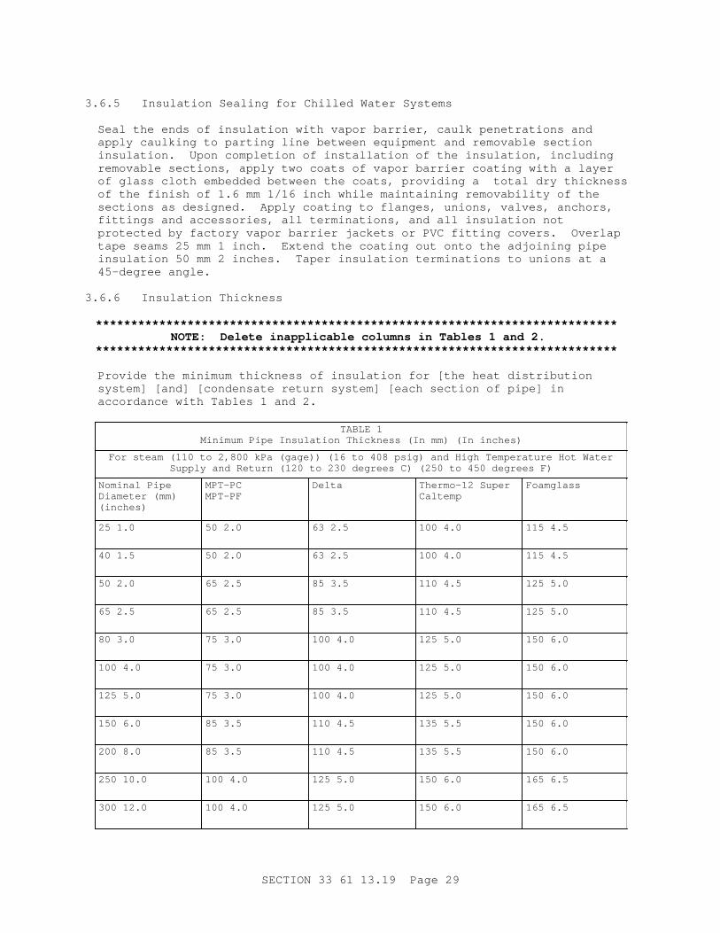
3. 6. 5 I nsul at i on Seal i ng f or Chi l l ed Wat er Syst ems
Seal t he ends of i nsul at i on wi t h vapor bar r i er , caul k penet r at i ons and appl y caul k i ng t o par t i ng l i ne bet ween equi pment and r emovabl e sect i on i nsul at i on. Upon compl et i on of i nst al l at i on of t he i nsul at i on, i nc l udi ng r emovabl e sect i ons, appl y t wo coat s of vapor bar r i er coat i ng wi t h a l ayer of gl ass c l ot h embedded bet ween t he coat s, pr ovi di ng a t ot al dr y t hi ckness of t he f i ni sh of 1. 6 mm 1/ 16 i nch whi l e mai nt ai ni ng r emovabi l i t y of t he sect i ons as desi gned. Appl y coat i ng t o f l anges, uni ons, val ves, anchor s, f i t t i ngs and accessor i es, al l t er mi nat i ons, and al l i nsul at i on not pr ot ect ed by f act or y vapor bar r i er j acket s or PVC f i t t i ng cover s. Over l ap t ape seams 25 mm 1 i nch. Ext end t he coat i ng out ont o t he adj oi ni ng pi pe i nsul at i on 50 mm 2 i nches. Taper i nsul at i on t er mi nat i ons t o uni ons at a 45- degr ee angl e.
3. 6. 6 I nsul at i on Thi ckness
**************************************************************************NOTE: Del et e i nappl i cabl e col umns i n Tabl es 1 and 2.
**************************************************************************
Pr ovi de t he mi ni mum t hi ckness of i nsul at i on f or [ t he heat di st r i but i on syst em] [ and] [ condensat e r et ur n syst em] [ each sect i on of pi pe] i n accor dance wi t h Tabl es 1 and 2.
TABLE 1Mi ni mum Pi pe I nsul at i on Thi ckness ( I n mm) ( I n i nches)
For st eam ( 110 t o 2, 800 kPa ( gage) ) ( 16 t o 408 psi g) and Hi gh Temper at ur e Hot Wat erSuppl y and Ret ur n ( 120 t o 230 degr ees C) ( 250 t o 450 degr ees F)
Nomi nal Pi pe Di amet er ( mm) (inches)
MPT-PCMPT-PF
Delta Ther mo- 12 Super Caltemp
Foamglass
25 1. 0 50 2. 0 63 2. 5 100 4. 0 115 4. 5
40 1. 5 50 2. 0 63 2. 5 100 4. 0 115 4. 5
50 2. 0 65 2. 5 85 3. 5 110 4. 5 125 5. 0
65 2. 5 65 2. 5 85 3. 5 110 4. 5 125 5. 0
80 3. 0 75 3. 0 100 4. 0 125 5. 0 150 6. 0
100 4. 0 75 3. 0 100 4. 0 125 5. 0 150 6. 0
125 5. 0 75 3. 0 100 4. 0 125 5. 0 150 6. 0
150 6. 0 85 3. 5 110 4. 5 135 5. 5 150 6. 0
200 8. 0 85 3. 5 110 4. 5 135 5. 5 150 6. 0
250 10. 0 100 4. 0 125 5. 0 150 6. 0 165 6. 5
300 12. 0 100 4. 0 125 5. 0 150 6. 0 165 6. 5
SECTI ON 33 61 13. 19 Page 29

TABLE 1Mi ni mum Pi pe I nsul at i on Thi ckness ( I n mm) ( I n i nches)
For st eam ( 110 t o 2, 800 kPa ( gage) ) ( 16 t o 408 psi g) and Hi gh Temper at ur e Hot Wat erSuppl y and Ret ur n ( 120 t o 230 degr ees C) ( 250 t o 450 degr ees F)
350 14. 0 100 4. 0 125 5. 0 150 6. 0 165 6. 5
400 16. 0 100 4. 0 125 5. 0 150 6. 0 165 6. 5
450 18. 0 100 4. 0 125 5. 0 150 6. 0 165 6. 5
TABLE 2Mi ni mum Pi pe I nsul at i on Thi ckness ( I n mm) ( I n i nches)
For Low Pr essur e St eam ( l ess t han 110 kPa ( gage) 16 psi g) , Condensat e Ret ur n and LowTemper at ur e Hot Wat er ( l ess t han 120 degr ees C 250 degr ees F)
Nomi nal Pi pe Di amet er ( mm) (inches)
MPT-PCMPT-PF
Delta Ther mo- 12 Super Caltemp
Foamglass
25 1. 0 40 1. 5 50 2. 0 80 3. 0 80 3. 0
40 1. 5 40 1. 5 50 2. 0 80 3. 0 80 3. 0
50 2. 0 40 1. 5 50 2. 0 80 3. 0 80 3. 0
65 2. 5 40 1. 5 50 2. 0 80 3. 0 80 3. 0
80 3. 0 50 2. 0 65 2. 5 85 3. 5 85 3. 5
100 4. 0 50 2. 0 65 2. 5 85 3. 5 85 3. 5
125 5. 0 50 2. 0 65 2. 5 85 3. 5 85 3. 5
150 6. 0 65 2. 5 80 3. 0 110 4. 5 110 4. 5
200 8. 0 65 2. 5 80 3. 0 110 4. 5 110 4. 5
250 10. 0 80 3. 0 100 4. 0 125 5. 0 125 5. 0
300 12. 0 80 3. 0 100 4. 0 125 5. 0 125 5. 0
350 14. 0 80 3. 0 100 4. 0 125 5. 0 125 5. 0
400 16. 0 80 3. 0 100 4. 0 125 5. 0 125 5. 0
450 18. 0 80 3. 0 100 4. 0 125 5. 0 125 5. 0
3. 7 VALVE MANHOLES AND ACCESSORI ES
**************************************************************************NOTE: Pr ovi de desi gn det ai l s on dr awi ngs of concr et e r ei nf or c i ng, s i ze, di mensi ons of val ve manhol e, pi pi ng ar r angement s, t ype of r emovabl e cover , val ve manhol e penet r at i ons, pi pe and
SECTI ON 33 61 13. 19 Page 30

equi pment suppor t s, et c.**************************************************************************
3. 7. 1 Pi pi ng and Equi pment i n Val ve Manhol es
Pr ovi de easy access i n val ve manhol es wi t hout st eppi ng on pi pi ng or equi pment , and al l ow suf f i c i ent wor ki ng ar ea f or mai nt enance wor k. Ref er t o dr awi ngs of pi pi ng and equi pment i n val ve manhol es f or i nst al l at i on and suppor t det ai l s . I nst al l al l gl obe, angl e and gat e val ves wi t h t he st ems hor i zont al or above.
Submi t Dat a Package 2 as r el at ed t o al l equi pment pr ovi ded f or t he pr oj ect i n accor dance wi t h Sect i on 01 78 23 OPERATI ON AND MAI NTENANCE DATA. Det ai l i n t he oper at i on manual s t he st ep- by- st ep pr ocedur es r equi r ed f or equi pment st ar t up, oper at i on, and shut down. I ncl ude i n t he oper at i on manual s t he manuf act ur er ' s name, model number , par t s l i s t , and br i ef descr i pt i on of al l equi pment and t hei r basi c oper at i ng f eat ur es. Li s t i n t he mai nt enance manual s r out i ne mai nt enance pr ocedur es, possi bl e br eakdowns and r epai r s, and t r oubl eshoot i ng gui des. I ncl ude i n t he mai nt enance manual s pi pi ng and equi pment l ayout and si mpl i f i ed wi r i ng and cont r ol di agr ams i ndi cat i ng l ocat i on of el ect r i cal component s wi t h t er mi nal s desi gnat ed f or wi r i ng, as installed.
3. 7. 2 Sump Pumps I nst al l at i on
**************************************************************************NOTE: Coor di nat e t hi s par agr aph wi t h t he speci f i ed r equi r ement s i n par agr aph SUMP PUMPS.
**************************************************************************
I nst al l sump pumps as i ndi cat ed, wi t h al l el ect r i cal connect i ons har d wi r ed. [ Connect moni t or i ng of each pump mot or and t he hi gh wat er al ar m t o t he Ener gy Moni t or i ng and Cont r ol Syst em ( EMCS) . Coor di nat e el ect r i cal r equi r ement s of EMCS wi t h Sect i on 26 20 00 I NTERI OR DI STRI BUTI ON SYSTEM] . Pr ovi de dedi cat ed el ect r i cal c i r cui t s t o t he sump pumps. Pr ovi de al l c i r cui t br eaker s and swi t ches i n t he el ect r i cal power di st r i but i on t o t he sump pumps wi t h t he capabi l i t y of bei ng l ocked i n t he " ON" posi t i on t o be s i gned as f ol l ows. St amp t he wor ds f or t he s i gn on a cor r osi on r esi st ant met al pl at e wi t h l et t er s 10 mm 3/ 8 i nch hi gh, and af f i x t he pl at e per manent l y near t he swi t ch or c i r cui t br eaker .
THI S CI RCUI T SUPPLI ES POWER TO THE ELECTRI C SUMP PUMPS I N THE UNDERGROUND DI STRI BUTI ON SYSTEM. THI S CI RCUI T MUST BE " ON" AT ALL TI MES; OTHERWI SE EXTENSI VE DAMAGE WI LL OCCUR TO THE UNDERGROUND HEAT DI STRI BUTI ON SYSTEM AND PREMATURE FAI LURE WI LL OCCUR.
3. 8 TESTS
Per f or m t est s of pi pi ng i n t he val ve manhol es as par t of t he t est i ng of t he di r ect bur i ed condui t syst em. I i ncl ude t he pi pi ng i n t he val ve manhol e i n t hese t est s and per f or m i n accor dance wi t h t he syst em suppl i er ' s Appr oved Br ochur e or t he cont r act speci f i cat i ons.
- - End of Sect i on - -
SECTI ON 33 61 13. 19 Page 31