Embed Size (px)
Citation preview

UBBINK SOLAR IN-ROOF SYSTEM
Installation guide
The integrated solar mounting system

UBBINK SOLAR IN-ROOF SYSTEM
Table of contents
Solar In-Roof System introduction p3
System components p4
Installation guide p5
1. Roof preparation p5
2. Install Ubiflex p6
3. Position the in-roof roll p7
4. Fixing the anchors p8
5. Position the angle brackets p9
6. Install the zinc side flashings p9
7. Slate roofs p10
8. Fixing the rails p11
9. Adjustment of the rails p12
10. Install PV modules p12
11. Position the expanding foam tape p13
12. Flat tiles and slates p14
13. Completing the photovoltaic field p14
14. Ubbink solar systems overview p15
2 I 3 Ubbink - Solar energy systems
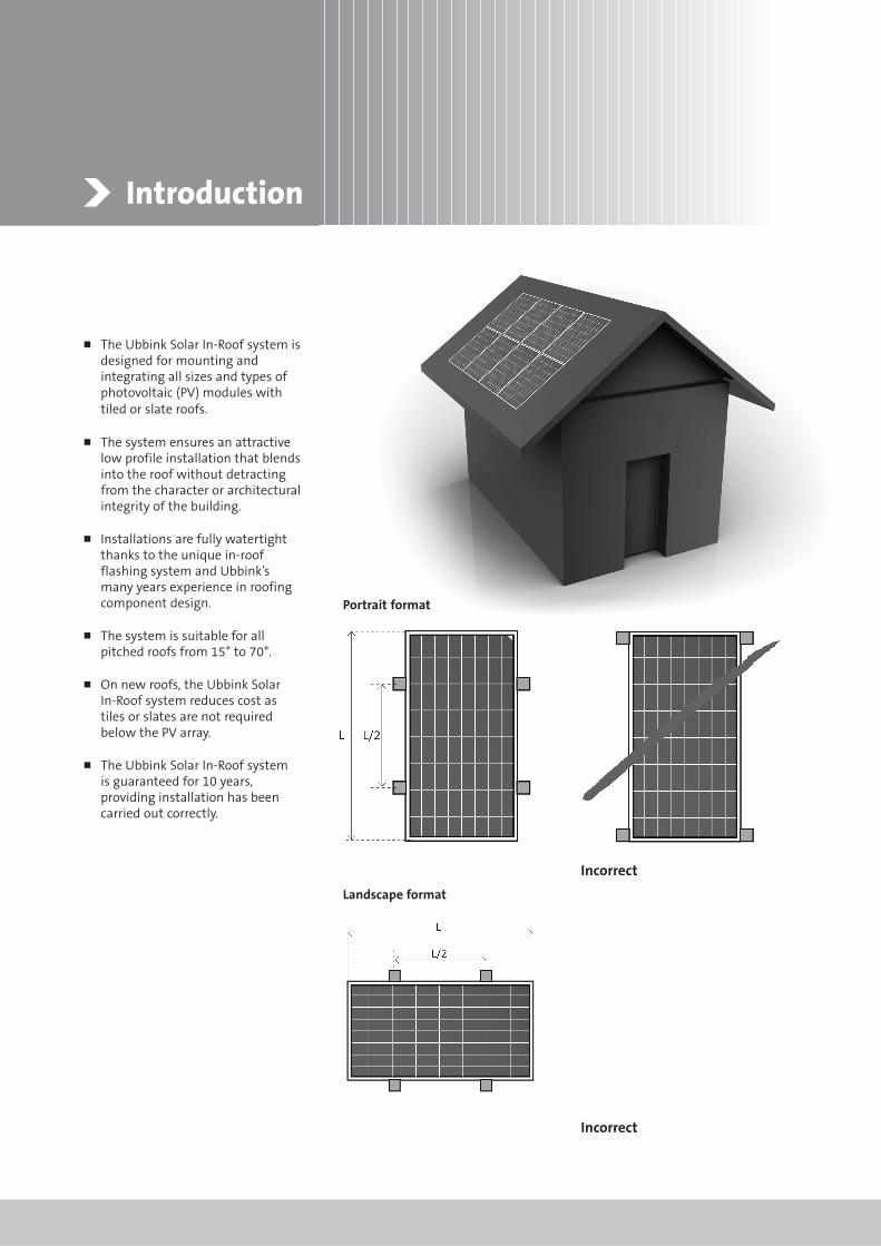
Introduction
� The Ubbink Solar In-Roof system isdesigned for mounting andintegrating all sizes and types ofphotovoltaic (PV) modules withtiled or slate roofs.
� The system ensures an attractivelow profile installation that blendsinto the roof without detractingfrom the character or architecturalintegrity of the building.
� Installations are fully watertightthanks to the unique in-roofflashing system and Ubbink’smany years experience in roofingcomponent design.
� The system is suitable for allpitched roofs from 15° to 70°.
� On new roofs, the Ubbink Solar In-Roof system reduces cost astiles or slates are not requiredbelow the PV array.
� The Ubbink Solar In-Roof system is guaranteed for 10 years,providing installation has beencarried out correctly.
Portrait format
Landscape format
Incorrect
Incorrect

4 I 5 Ubbink - Solar energy systems
System components
IN-ROOF ROLL
EXPANDING FOAM ROLL
SIDE FLASHING ALUMINIUM RAIL
ANCHOR
END CLAMP
ANGLE BRACKET MID CLAMP
RAIL CONNECTOR UBIFLEX 400MM (OPTIONAL)
WATERPROOF SCREWS
The above images are representative and may change accordingly.

Installation guide
1 Roof preparation
� Ensure correct tools are to hand:hacksaw; 13mm socket spanner;5mm Allen key; Torx T25 driver;rubber mallet; angle grinder;chalk line.
� Calculate the photovoltaic field(height x width) + 20mm spacingbetween modules.
� Remove the tiles / slates thatcover the area calculated above.
� Remove an additional column oftiles on both the right and lefthand side (2 rows for slates).
� Remove an additional row of tilesabove the calculated photovoltaicfield (2 rows for slates).
� Do not remove any additional tilesbelow the photovoltaic field (forslate leave the first row of hooks).
� Check the quality of the battens. If you are in even the slightestdoubt about their condition,always replace them. As preferredbest practice we always adviseplacing new battens alongside the old ones.
� Ideal batten spacing is 300mm;replacement or additional battensshould be the same thickness asthe existing battens.
Portrait format Landscape format
Width of field
Hei
ght
of f
ield
Hei
ght
of f
ield
Width of field
Slate roofRemove additional 2 columns on either side
and an additional 2 rows above thephotovoltaic field
Tile roofRemove additional column on either side
and an additional row above the photovoltaic field

6 I 7 Ubbink - Solar energy systems
� Use 400mm wide Ubiflex (for veryhigh profile tiles 500mm may berequired). This is available in black,grey or terracotta.
� 240mm above the batten holdingthe row of tiles below the arrayadd an additional batten over thewidth of the field. The size of theadditional batten should be theequivalent of the original battenspecification. A further additionalbatten is advisable immediatelybelow the other additional battenif the pitch is below 20°.
� With a 50mm overhang above, roll out and screw the top of theUbiflex to the newly installedbatten at 450mm centres.
� Fold back the 50mm overhang of Ubiflex.
� Fold back both right and left hand sides in the same manner.
� Carefully dress the Ubiflex overthe first row of tiles and stuckdown with Ubbink High Tackalong the leading edge. Avoidcreating areas where water might pond.
� Alternatively the Ubiflex can run450mm beyond each side of thephotovoltaic fields to form atraditional soaker detail.
2 Install Ubiflex
Ubiflex – black, grey or terracotta
240mm
20mm
20mmScrews
Ubiflex
The above images are representative and may change accordingly.

3 Position the in-roof roll
� Position the in-roof roll at the bottom left of the field.
� Position so the lugs at the topedge rest on a convenient battenso that the lower part of the rolloverlaps the Ubiflex by at least150mm or 200mm if the pitch isless than 20°.
� Unroll the in-roof roll across thephotovoltaic field being carefulnot to stretch and distort the rollprofiles otherwise the followingroll will not fit.
� If the in-roof roll is too long, cut tothe desired length and keep theoff cut for the next row.
� If the in-roof roll is too short,unroll it until the end and thenuse a second roll with a 250mmoverlap between the two rolls.
� The in-roof roll head laps shouldbe a minimum of 150mm or200mm if the pitch is less than20°, but centred to fill the photovoltaic field.
� Tack in place with a nail below lap,or if open fixing, use watertightscrews on the flat of the profile.
� Install cable for connectionthrough the overlap, three ridgeprofiles in.
NOTE: For slates,slip the in-roofroll into the first row of hooks leftin place.
In-roof roll lugs (do not stretch roll)
150mm
250mm

8 I 9 Ubbink - Solar energy systems
Portrait format
� Position the first anchor 200mmaway from the left hand side, so that a quarter of the PVmodule will fall between theanchor and the bottom of thephotovoltaic field. These are fixedto the batten using three of theprovided anchor screws peranchor.
� Position the subsequent anchorrows as follows: No more than amaximum of 900mm wide overthe length of the rows andapproximately half the length ofthe PV module for the distancebetween the heights of the rows.
4 Fixing the anchors
Fix the entire row of anchors at theirfirst position at the bottom of thephotovoltaic field.
Landscape format
� Position the first anchor 200mmabove the bottom of photovoltaicfield and a quarter of the PVmodule away from the lefthand side. These are fixed to thebatten using three of the providedanchor screws per anchor.
� Position the subsequent anchorrows as follows: No more than amaximum of 900mm widthbetween the height of the rowsand approximately half the lengthof the PV module for the distancebetween the anchors along thelength of the rows.
The above images are representative and may change accordingly.

5 Position the angle brackets
� Screw the angle brackets to theanchors (do not tighten).
� Place the hammerhead bolt andnut onto the angle bracket
� Place the side flashing so thatit covers the last crest of themerge roll.
� This flashing serves to makewatertight the position betweenthe merge roll and the tiles orslates. Very little of the flashingshould be visible once theinstallation is complete.
� Fixed on first batten then everyother batten.
The exact final position of the flashingis adjustable within the trough of themerge roll.
6 Install the side flashings
Side flashing
Side flashing
Last crest of the in-roof roll
Hammerhead bolt
Anchor
Angle bracket

10 I 11 Ubbink - Solar energy systems
� Slate roofs require that the Ubiflexflashing is positioned at the top ofthe system.
� Position the 400mm wide Ubiflexapproximately 200mm above thein-roof roll, with 20mm extendingpast the top batten. Unroll acrossthe whole width of the PV field,screwing to the batten at the topedge of the roll.
� Fold the top edge back by 20mm.
� Bend both left and right handsides back 20mm in the samemanner along two thirds of the height.
� Bend the top left and rightextremities in the same manner.
� Dress the bottom 200mmcarefully over the in-roof roll.
7 Slate roofs
20mm
20mm
200mm
The above images are representative and may change accordingly.

8 Fixing the rails
Portrait format
� To install photovoltaic modules inportrait format, the rails need to bepositioned horizontally.
Landscape format
� To install photovoltaic modules inlandscape format, the rails need tobe positioned vertically.
� Cut aluminium rails to length; referto component list produced witheach order.
� Assemble the full rail run lengthusing the rail connectors.
� Slide the first rail to the centre rivet by giving a light blow withthe mallet and then push intosecond rail.
� Position rails against the anglebrackets and tighten nut slightly.
� Centre the rails over the merge roll,horizontally for portrait andvertically centred for landscape.
� When installed vertically an 'endcap' should be used on both endsper rail.
Portrait format
Landscape format
Rail connector
Rail

12 I 13 Ubbink - Solar energy systems
9 Adjustment of the rails
� This stage is very important for thePV modules to be mounted correctly.
� Align the rails (vertically orhorizontally dependant on theorientation as specified on page 11)using the chalk line.
� Ensuring these alignments arecorrect will result in perfectalignment of the photovoltaic fieldand that it will be flat, well balancedand aesthetically pleasing.
� Once the rails are correctly aligned,tighten all the nuts and bolts.
� Always start at the bottom.
� Align end clamp at the end of therail and slide into position.
� Position the first PV module andtighten end clamp.
� Position the second PV modulebeside the first module.
� Fix this module into position, with mid clamp for portraitformat or end clamp for landscape format.
� Continue mounting the PVmodules in accordance withelectrical connection diagram.
10 Installing PV modules
End clamp
Mid clamp
End clamp
Mid clamp
The above images are representative and may change accordingly.

11 Positioning the expanding foam tape (for tiles only)
� Apply the expanding foam rollonto the side flashings on bothleft and right hand sides to theedges of the photovoltaic field.
� Also apply the expanding foamtape to the merge roll just abovethe photovoltaic field.
� The foam corner junction should be formed tightly butwithout overlaps.
Side flashing fixing behind the joint
Batten
Expanding foam tape
Expanding foam tape

13 Completing the photovoltaic field
� Fix first row of end clamps and mount first row of PV modules,connecting the module cables as you go.
� Modules should have a 20mm gap between them. The top partof a mid clamp makes a perfecttemporary spacer.
� Slide on mid clamps, add nextrow of modules and repeat until last row of end clamps required.
� When all modules are correctly adjusted and positioned, tighten clamps.
� Replace the rows of tiles / slates previously removed around the side and top of the photovoltaic field.
14 I 15 Ubbink - Solar energy systems
12 Flat tiles and slates
� The merge roll should finish justshort of the top batten, free to bendinto position under tile or slate.
� The outer lip on side flashing shouldbe turned in and flattened, allowingtile to butt onto flashing.
Allen bolt
Mid clamp
End clamp
The above images are representative and may change accordingly.

14 Ubbink solar mounting systems overview
Ubbink Solar In-Roof System
The Ubbink Solar In-Roof mountingsystem integrates PV modules into slateor tiled roofs, ensuring an attracive andlow profile appearance. The system isfully watertight and easy to install. TheUbbink Solar In-Roof mounting system istypically installed on new roofs where itreduces cost as tiles or slates are notrequired below the PV array.
Ubbink Solar On-Roof System
The Ubbink Solar On-Roof mountingsystem is simple, fast, economical andsuitable for all slate and tiled roofs. The PV modules are fixed to a mountingassembly just above the existing roof. TheUbbink Solar On-Roof mounting systemis typically installed on existing roofs.
Ubbink Solar Flat Roof System
The Ubbink Solar Flat Roof mountingsystem positions PV modules to facesouth at the optimal angle. This is amodular ballasted system that sits on theflat roof ensuring no roof penetrationfrom fixings through the roof membrane.This system can be fitted and positionedvery quickly on flat roof buildings up to25m high.

Ubbink (UK) LtdBorough RoadBrackleyNorthantsNN13 7TB
T. +44 1280 700211F. +44 1280 705332
www.ubbink.co.uk
Less energy, more comfortwww.ubbink.co.uk
www.ubbink.ie
Ubbink IrelandUnit 81, Cherry Orchard Industrial Estate,Ballyfermot, Dublin, Ireland.
T. +353 (0)1 626 2600, +353 (0)1 626 2558 F. +353 (0)1 626 2605