Embed Size (px)
Citation preview

Type HPC High Pressure Contact Switches � · / "\

General Information . . . . . . . . . . . . . . . . . . . . . . . . . . 3
Application
Equipment Use . . . . . . . . . . . . . . . . . . . . . . . . . . . . . II Top and Bottom Feed Switches . . . . . . . . . . . . . . . . II Integral Ground Fault and
Related Trip Time Curves . . . . . . . . . . . . . . . . . . I3
Product Selection
Catalog Numbers . . . . . . . . . . . . . . . . . . . . . . . . . . . . IS Access9ries . . . . . . . . . . . . . . . . . . . . . . . . . . . . . . . . . I9 Ground Break® Components . . . . . . . . . . . . . . . . . . 22
Application Data and
Outline Drawings . . . . . . . . . . . . . . . . . . . . . . . 24
Specifications
Detailed Specifications . . . . . . . . . . . . . . . . . . . . . . . 29 Guide Form Specifications . . . . . . . . . . . . . . . . . . . . 3I
2

UL Listed-Standard No. 977, "Fused Power Circuit Devices."
Features
• High interrupting capability-1 2X minimum make and break without fuses to insure complete coordination with Class L fuses and with ground fault tripping.
• Integral self.powered, zero-sequence ground fault protection provides reliable solid state ground fault sensing;
GE's Type HPC High Presure Contact Switches are butt-type, multiple contact fusible high-capacity interrupters for use as:
not dependent on control power.
• Top or bottom feed are same physical size for simplified bus and layout work and optimum flexibility for switchboard and panel builders.
• Compact and l ightweight for greater switchboard loading and lower shipping costs.
• High Durability High-dielectric strength, polyester glass reinforced insulating case for safe operation.
• High Interrupting Capability
Arc chute of unique conslruction suppresses arcs and cools gases rapidly, providing quick arc interruption and extended switch life.
• Extended Transient Voltage Withstandability
Integrally molded interphase partitions mesh with switch cover to completely isolate each pole.
• Extended Switch Life
Multiple, preloaded butt-type movable contact arms pivoted in a solid copper block require no maintenance.
• Positive "ON-OFF" Indication
Red (ON), Green (OFF), eliminates any question about the position of the switch contacts.
• Easy Operation-Quick Mode
Extra heavy duty, low torque rotary operated closing mechanism. L-handle 800-I600A; T-handle 2000-4000A.
• Emergency Open-Quick Break
Finger-tip "OFF" button instantly opens the switch contacts.
• Positive Door and Switch Interlocking-No Fuse Access Door Required
• Fuse Mounting Bolts with Captive Washers for Ease of Mounting Fuses
• Main Service Disconnects
• Feeder Disconnects
• Branch Circuit Disconnects
• Motor Circuit Disconnects
3

SOOA 1 200A and 1 600A 2000A
2500A 3000A 4000A
4

Top Feed
Bottom Feed
"Top feed" or "bottom feed" defines the physical position of the line and load terminals of the switch: at the top or at the bottom of the switch, depending on the application. The bottom feed or "line bottom" feature permits economical and simplified bus design or significantly less cable and cable bending when the power cables enter the switch enclosure or cubicle from ground or floor leveL Top and bottom feed devices are the same size.
Electric Trip Manual Trip
Manual Trip
Use the "Push Off' button. Select the manual switch when ground fault or remote tripping are not required.
Electric Trip
Specify "electric trip" (catalog numbers with suffix ET l or ET2). This permits tripping from a remotely located push button, providing an added degree of safety and convenience. Electrically tripped devices can also be manually tripped by the "Push Off' button. GE Ground Bus® components can be used with an electrically tripped switch to provide zone selective ground fault protection.
Integral Ground Fault
This unique system incorporates a zero-sequence current sensor and relay factor mounted as an integral part of the switch. It is self-powered and available with ground fault indicator and test functions. No control wiring is required except to tie in the "4th wire" neutral current sensor when applicable. Separate installation of the neutral current sensor is an added benefit of HPC with integral ground fault because it eliminates bringing the neutral busbar(s) out to the front of the switch and through the phase current sensor. The neutral sensor can therefore, be installed where most convenient.
5

In the early 1900's the equipment most commonly used for manual switching and disconnecting devices was the open knife switch. It consisted of a stationary 'jaw", a movable "blade" pivoting in a hinge post and, for fusible forms, two fuse holders. It carried current adequately, but left "something to be desired" from a safety standpoint as a load· make, load·break device because it relied on the operator to open or close the blade quickly. Early forms of "bolted· pressure" contact switches employed this basic open knife switch concept with a "mechanism" used to open and close. They improved the current·carrying ability by adding "bolted" blade/jaw joints; but as interrupters, they were in· adequate. Why? Because the "unbolting" of the joints and the large copper mass did not allow fast acceleration of the part· ing (or closing) blade . . . again a safety problem.
Open Knife Switch
GE's high pressure contact switch design improved on the original concept. GE uses high·conductivity silver/tungsten· carbide alloy contacts welded to multiple lower·mass arms which butt against stationary contacts welded on a copper pad. Each movable contact arm is spring·loaded against the stationary contact, achieving independent, low·resistance, high pressure 'joints".
HPC Switch Mechanism
6
An over·center toggle mechanism with high·energy springs achieves higher acceleration of parting (or closing) 'joints". This taster parting of arcing arms from the stationary members draws the arc more quickly into large arc quen· chers which cool and rapidly extinguish the arc. All GE HPC switches are capable of repeatedly making and breaking l 2X rated current at rated voltage (600V ac); UL requires break· ing 12X rated current for Class I ground fault use only. In fact, it is this fast·acting operation that, for operator safety, necessitates this high interrupting capability. If the switch 1s closed on a low level fault and immediately opened, the switch must be capable of clearing the fault (before the current·limiting fuse has blown).
What Is A Fused Power Circuit Device?
GE type HPC switches are fusible interrupters designed for high available fault current systems. They are suitable for use as main service disconnects, feeder disconnects, or branch circuit disconnects. They can be used only with NEMA Class L current·limiting fuses and when so employed are suitable f(>r use on systems capable of delivering up to 200,000 rms amperes symmetrical fault current at 600V ac, maximum.
They are UL listed in accordance with UL977, Standard f(>r Safety, Fused Power Circuit Devices.
Why HPC?
The HPC design provides additional safety while meeting the same requirements as the older, more traditional, bolted· pressure contact switches in which the blade and jaw com· bination is squeezed together in the fully closed position. UL Standard 977 fully recognizes both constructions. The HPC provides the added benefit of inherent high interrupting capability . . . it's designed·in.
Contact Assembly
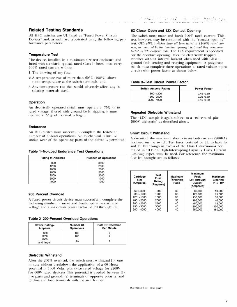
Related Testing Standards All HPC switche' are UL listed as "Fused Power Circuit Devices" and, as such, are type-tested using the following performance parameters:
Temperature Test
The device, installed in a minimum size test enclosure and fused with standard, typical, rated Class L fuses, must earn 100 % rated current without:
l . The blowing of any fuse,
�-A temperature rise of more than 60°C ( 1 OH°C) above room temperature at the switch terminals, and.
c). Am temperature rise that would ad\erseh affect am insulating materials used_
Operation
An clectricalh operated switch must operate at 759i- of its rated voltage; if used with ground Lntlt tripping, it must operate at :i59� of its rated voltage.
Endurance
An HPC: switch must successful!\ complete the followingnum ber of no-load operatiow,_ l\o mechanical L!ilurc m· undue wear of the operating parts of the deivce i' permitted.
Table 1-No-Load Endurance Test Operations
Rating In Amperes Number Of Operations
BOO 3500 1200 2500 1600 2000 2000 2000 2500 2000 3000 1000 4000 1000
200 Percent Overload
A fused power circuit device must successful!\ complete the following number of make and break operations at rated voltage and a maximum power factor of .70 through .HO.
Table 2-200-Percent Overload Operations
Device Rating- Number Of Rate Of Operation Amperes Operations Per Minute
BOO 100 2 1200 100 1 1600 50 1 and larger
Dielectric Withstand
After the 200 % overload, the switch must withstand for one minute without breakdown the application of a 60 Hertz potential of 1 000 Volts, plus twice rated voltage (or 2200V for 600V rated devices). This potential is applied between (I) live parts and ground, (2) terminals of opposite polarity, and (3) line and load terminals with the switch open.
6X Close-Open and 12X Contact Opening
The switch must make and break GOO % rated current. This test, however, may be combined with the "contact opening" test. Gr:'s HPC switches havr all been tested at 1200% rated current, as required by the "contact oj;ening" test, and they were completed as "close-open" tests. The l �X requirement is specified for the "contact opening" tests for electricallv tripped switches without integral lockout when used with Class I ground bult sensing and relaying equipment. A polyphase switch must complete three operations at rated voltage (ope11 circuit) with power bctor as shown below.
Table 3-Test Circuit Power Factor
Switch Ampere Rating Power Factor
B00-1200 0.45-0.50 1600-2500 0.25-0.30 3000-4000 0.15-0.20
Repeated Dielectric Withstand
The "1 2X" sample is again subject to a "twice-rated plus 1000\' dielectric" as described abm-e.
Short Circuit Withstand
A circuit of the maximum short circuit Emit current (�OOKA) is closed on the switch. Test fuses. certified bv UL to ha\T Ip and I�t let-through in excess of the Class L maximums permitted in ULI9HC High-Interrupting Capacity Fuses. Current Limiting Tvpes. must be used. For reference, the maximum fuse kt-throughs are as follows:
Test Cartridge
Fuse Maximum
Size Rating
Threshold (Amperes) Ratio
(Amperes)
601-BOO BOO 30 B01-1200 1200 30
1201-1600 1600 35 1601-2000 2000 35 2001-2500 2500 40 2501-3000 3000 40 3001-4000 4000 40
(Continued on next page)
Maximum Peak
Let-Through Current
(Amperes)
BO,OOO 120,000 150,000 165,000 1BO,OOO 200,000 250,000
Maximum Clearing (2 X 10³
10,000 15,000 30,000 40,000 75,000
100,000 150,000
7

After the short circuit withstand test, the ground fuse must not have blown; there shall not be any breakage which might impair the integrity of mounted live parts; the enclosure door shall not have blown open; and the switch must be capable of being opened by its manual means. Power factor for this test is 20 % maximum. The test circuit is shown in Figure 1 .
the test circuit is closed by closing the HPC switch. For de· vices rated 150,000 or 200,000 rms amperes symmetrical, the closing test must also be conducted at 1 00,000 rms amperes at rated voltage.
Repeat Dielectric Withstand
Circuit Closing Test
After the closing test, the dielectric test is repeated, except the potential is twice rated voltage-that is 1 2000 volts.
Using the same circuit as for the short circuit withstand test,
8
Circuit For Withstand And Closing Tests
Supply Rated Voltage 3 Phase-60 Hertz
X - Variable tap air-core reactor
R - Variable resistor
SW - Closing Switch-may be located as shown or ahead of limiting impedance
F - Enclosure fuse
D - Device under text
R5 - Coaxial shunts for metering current
C.L. - Current-limiting fuses used during test. To be installed in switches or mounted externally as shown
DF - Dummy Face
Common connection of outer shells of coaxial shunts may be grounded if no other grounds on the circuit.
Figure 1 .
Related Listing Standards And Recognition Authorities For HPC Switches
l . Listed by Underwriters' Laboratories, Inc. (UL) Standard for Safety No. 977, Fused Power Circuit Devices.
2. Certified by Canadian Standards Association (CSA). Appli· cable requirements are CSA Standard C22.2.
3. Approved by the City of New York, NY, Department of Public Works.
4. Approved by the State of California, Department of Indus· trial Relations, Division of Industrial Safety.
R
F
TEST CL --FUSES

Versatile The GE HPC switch utilizes a proven, oven·enter toggle type, mechanism as the heart of the design. This mechanism provides the needed function for service disconnects to interrupt fault currents up to 200,000 amperes symmetrical at 600 volts ac. The GE HPC switch was specifically designed to comply with the National Electrical Code Article 230-65, which requires service equipment and its overcurrent protective devices to have short-circuit current rating equal to or greater than the available short-circuit current as its supply terminals.
Built-in Ground Fault Protection The integral ground fault HPC switch provides system ground fault protection. The integral, solid state ground fault relay has a adjustable ground fault pickup point from 200 to 1 100 amperes in six steps and ground fault time delay settings of minimum, intermediate and maximum. It is comletely self-powered and has a mechanical ground fault indicator and test functions which simulate an actual ground fault. Testing can be done with or without tripping the switch. External 1 20 V ac control power (200 volt-amperes min.) must be provided for testing only.
Ratings-1 00% Equipment Ratings Continuous current ratings permit use at 100% of nameplate ratings with rated Class L fuses. Per UL Stndard 977, no derating is necesary and all HPC switches are UL listed to carry 100 % current when used in an appropriately sized ventilated enclosure.
Interrupting Capability-The HPC switches will fully coordinate with rated Class L fuses at all short circuit currents up to 200,000 amperes RMS symmetricaL Comparatively low level fault currents are the most common; it is very important that the switch, once closed on such a fault, be capable of clearing the fault since the fuse opening may be slower than the switch opening. Furthermore, these fault levels are often below the fuse threshold and the current-carrying effect of the fuse is minimaL GE manual, electric trip, or integral ground fault HPC switches, equipped with Class L fuses, are fully capable of being opened or closed on any fault current of 200,000 amperes symmetriacl or less at 600 VAC.
Easy Operation Closing
Manual closing. Turning the switch "on" sets the mechanism. No other function need be performed to assure that the HPC switch is charged for interruption.
Opening
Manual "Push Off' button, electric trip, or integral ground fault trip. The operating mechanism responds to a manual release immediately upon actuation of the "off' button. The electric trip form provides the additional means of tripping the switch a Ground Break® relay or from a remote location. The electric trip and integral ground fault trip meet the UL requirements for operation at 55% of rated voltage on ground fault systems and have a maximum unlatching time of three cycles. All three forms are UL listed under Subject 977-Fused Power Circuit Devices.
Figure 2. HPC's compact design and small handle eliminate the need for a separate fuse access door.
9

Systems Consideration Table 5 The HPC switch, in combination with Class L fuses, is designed for distribution systems having an available symmetrical fault current of up to 200,000 amperes at 600 volts ac. In addition, the switch is designed to close-in on and interrupt a wide range of currents, including normal switching duty currents and intermediate fault currents of at least 1 2 times the nameplate rating of the switch. This means full coordination with any UL listed rated size Class L fuse. Paragraph 3 1 . 1 of UL 977 only requires three 1 2X "interrup· tions" on contact opening operations at rated voltage for use with Class I ground fault sensing and relaying equipment. UL 977 does not, however, require "closing-in" on 1 2 times nameplate rated current.
4000A Switch Contact CLOSE-OPEN TestNo Fuses
Key to Oscillogram in Figure 3
a - Voltage timing trace (60 Hz)
b - "A") c - "B" Phase current d - "C"
e - "A") f - "B" Voltage across switch � - "C" contacts
Test Circuit-52,000 rms symmetrical, 600Vac, .2pf, 3 phase
SWITCH CONTACTS CLOSE HERE
Switch Rating
800 1200 1600
2000 2500
3000 4000
Actual Make And Break Current RMS Amperes Symmetrical
600V ac, 3-Phase
19,200 19,200 19,200
30,000 30,000
52,000 52,000
Figure 3.
Power Factor, o/o Max.
.50
.50
.30
.30
.30
.20
.20
SWITCH CONTACTS CLEAR HERE
Oscillogram of an actual close-open operation on a 52,000 rms, symmetrical available, 600 Vac, .2 pf, 3-phase circuit.
10

Equipment Use The 800-4000A HPC switches are available as manual trip switches, electric trip, or with integral ground fault protection (all are of top feed or bottom feed configuration)-all with optional accessirics. They are primarily intended for use as switchboard mains and feeders and for separate service interrupters. The versatile bottom feed construction (see Figure 4) permits line cables or busbars entering at floor level to be terminated directly to the line terminals of the switch without costly "looping" to get to the top of the switch. Sec Figure 4a. Similarly, by using one top feed and one bottom feed HPC switch as feeders, as shown in Figure 5, each feeder disconnect can be bussed directly from the feeder bus to the HPC switches without long runs of adapter bussing. See Figure 5a.
Today's more sophisticated, higher energy-demand systems and their inherently higher short-circuit fault current capability require a fused interrupter designed specifically for this purpose. The HPC switch fills this need.
Bottom-Feed Safety Simplified bus design achieved with bottom feed means: ( 1 ) easier bus maintenance, (2) fewer joints, (3) bus work is easily insulated and isolated for safer equipment.
Using Bottom-Feed HPC Switch
LOAD OR FEEDER
LOAD
Figure 4. Bottom feed service entrance equipment.
Using Bottom-Feed HPC Switch
Figure 5. Use of bottom-feed feeder disconnects simplifies switchboard construction and saves bussing.
Without Bottom-Feed HPC Switch
LINE
Figure 4a. Service entrance bus, or cables must be looped up to line terminals at top of switch (noted by bold lines).
Without Bottom-Feed HPC Switch
Figure Sa. Bold lines show additional bussing required with two top-feed switches.
11
12
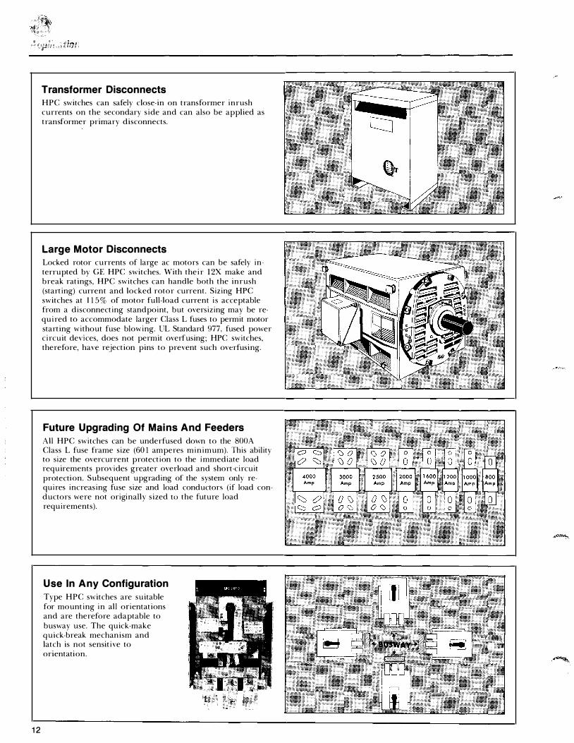
Transformer Disconnects HPC switches can safely close-in on transformer inrush currents on the secondary side and can also be applied as transformer primary disconnects.
Large Motor Disconnects Locked rotor currents of large ac motors can be safely interrupted by GE HPC switches. With their l 2X make and break ratings, HPC switches can handle both the inrush (starting) current and locked rotor current. Sizing HPC switches at 1 1 5 % of motor full-load current is acceptable from a disconnecting standpoint, but oversizing may be required to accommodate larger Class L fuses to permit motor starting without fuse blowing. UL Standard 977, fused power circuit devices, does not permit overfusing; HPC switches, therefore, have rejection pins to prevent such overfusing.
Future Upgrading Of Mains And Feeders All HPC switches can be underfused down to the SOOA Class L fuse frame size (60 1 amperes minimum). This ability to size the overcurrent protection to the immediate load requirements provides greater overload and short-circuit protection. Subsequent upgrading of the system only requires increasing fuse size and load conductors (if load conductors were not originally sized to the future load requirements).
Use In Any Configuration Type HPC switches are suitable for mounting in all orientations and are therefore adaptable to busway use. The quick-make quick-break mechanism and latch is not sensitive to orientation.
System Coordination And Selectivity HPC integral ground fault protection was developed specifically to coordinate with the various overcurrent and ground fault protective devices commonly used in today's modern distribution systems. Figure 8, page 1 4 is a reduced copy of the HPC integral ground fault time-current curves, GES-6 177. Curves on page 15 incorporate time-current curves for related protective devices. It is to be noted the ground fault trip curves are situated well to the left of the fuse curves indicating, for all levels of ground fault currents, the switch will be tripped by the ground fault sensing before the main fuse blows.
Likewise, Figure 9 shows that downstream branch circuit fus· ing will open on a ground fault current before the HPC ground fault sensing will trip the main disconnect. It is this "knee" in the ground fault curves that permits a 60A RK5 fuse and a 200A Class J fuse to clear the downstream branch circuit ground fault without tripping the main or feeder disconnects.
Thus, branch circuits using up to 60A-80A Class RK5 time delay fuses, or up to 200A-250A Class J fuses, will be cleared without the integral ground fault tripping the upstream (main or feeder) HPC switch. This degree of system selectivity and coordination cannot be surpassed with other systems except at the sacrifice of longer delay time.
For specific values of branch fusing which will coordinate with the integral ground fault curve, it is highly recommended a coordination study be undertaken using actual manufac· turer's total-clearing time curves and GES-61 77.
Fast Unlatching Time Minimum unlatching time of the HPC switch with integral ground fault protection is 0.03 seconds for ground fault currents in excess of 8 times the pick-up setting with the time delay set on minimum. For ground fault currents below 8 times the pick-up setting, the trip time increases inversely with the current. This inverse relationship for ground fault currents up to about eight times the pick-up setting produces the unique "knee" in the time-current curve.
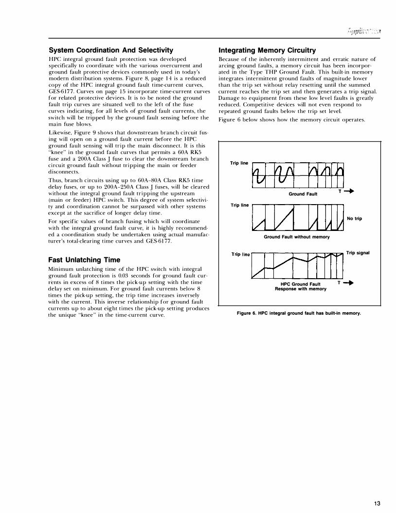
Integrating Memory Circuitry Because of the inherently intermittent and erratic nature of arcing ground faults, a memory circuit has been incorporated in the Type THP Ground Fault. This built-in memory integrates intermittent ground faults of magnitude lower than the trip set without relay resetting until the summed current reaches the trip set and then generates a trip signal. Damage to equipment from these low level faults is greatly reduced. Competitive devices will not even respond to repeated ground faults below the trip set level.
Figure 6 below shows how the memory circuit operates.
Trip line
Ground Fault
Trip line .. n-....... -.... 1.11---T"""---rn-T"""...,nn.-- .--........ l/1 v I l!1 lAJ;1 No trip
Ground Fault without memory
Trip ll•o� Trip,gMI
HPC Ground Fault T _,. Response with memory
Figure 6. HPC integral ground fault has built-in memory.
13

14
Trip-time Curves For Integral Ground Fault Function
! I 1 I 11 1000 4 ' . 11110 '" 0 0 70 '" ... .. 0 000
200
0 0 100
I I 70 .. 0 x.
� 40
" 0
! 2 0
0 • • 7 • ' • •
2
. .I �· �-7 •
.. . •
•
•
7
•
.0 ...
. 0
•
.0 2
1 ..
� N
Maximum Total Clearing Time A
� "
-� � �
� I'
Minimum Unlatching Time
. I .7 .1 .11 2 . . ' I 7
GENERAL . ELECTRIC I THPC/THPR Switch Ratings
800. 1 200. I 600. 2000, 2500. 3000. 4000 amperes
Voltage Rating 600 volts oc
Frequency Rating
Maximum
Nl'-Intermediate
_'\.
Minim':.m
. ..
MULTIPLES OF PICK·UP SETTING
30 40 so 101010108 -
" " " ['.._ I" � "" ""
'\. '\.
" 30 40 so 10 101010! MULTIPLES OF PICK-UP SETTING
HIGH PRESSURE CONTACT SWITCH
TYPE THP Integral Ground Fault Device
Ground Fault Plck·up and Delay
Time·current Curves
50/60 Hertz (Curves apply ol 50 60 Hertz or>d lrom 10 C To • 55 C amboenl'
f'-
-
; c
·� . ! � . . QU �0 �] 1i. Q. c
l GES·6177
Adjustments Ground Fault Untf Ptck-up Current 200. 300 400 600. 800. 1 1 00 amperes • l O% Delay Ttme Bands Ma:o:tmum, tnfermedtale and mmtmum
-1 ... ... 100 700 ... ... ... ... 200
1 00 .. u 70 u ..
1
1
.. .. "
.I .. .I
..
.. u
..

Coordination And Selectivity Of Downstream Overcurrent Devices
100 1,000
1 ,ooo.-----------
en c z 0 (.J LLI en z
TYPICAL SOA RK5 TIME
DELAY FUSE AVG. MELT TIME
HPC GROUND FAULT
MINIMUM UNLATCHING TIME
10,000 100,000
\ \ \ \
\ \ \ \ \
HPC GROUND FAULT
MAXIMUM TOTAL CLEARING TIME
TYPICAL CLASS L TOTAL CLEARING TIM
1200A
4000A
� \ \ \
\ \ \ \ \
The HPC Integral Ground Fault inverse time/constant time characteristic does not overlap branch circuit fuse curves, providing maximum c o ordin ation with downstre a m devices. Typical "Squ are Sh a p e" g ro u n d fault sensing methods do exhibit overlapping characteristics with downstream devices, thereby reducing systems selectivity and coordination.
--�10
-----·5
15

HPC SWITCH TERMINAL BLOCK
--------
� GROUND FAULT � I �OWERED LOGIC
INTEGRAL RELAY WITH TEST FUNCTION AND MECHANICAL GROUND FAULT INDICATOR
I I
��-t--t-' FLUX SHIFT TRIP SOLENOID
FLUX SHIFT TRIP INDICATOR
CUSTOMER WIRED
INTEGRAL 391 SENSOR
LOAD
NEUTRAL SENSOR (REQUIRED WHENEVER SYSTEM HAS SOLID NEUTRAL CONDUCTOR)
Figure 9. Block diagram
HPC Integral Ground Fault Test Procedures The reliability of the HPC integral ground fault system is excellent. However, since testing is so convenient, it is recommended that a test be performed monthly, or after the HPC switch has experienced a fault of any kind.
On-site Tests First connect l20V ac, 60 Hz external control power of at least 200 volt-amperes to terminals Land N as shown in Figure 9 above.
System Test Without Service Interruption (Can also be done with switch in "open" position if control power is then available.)
l . Push and hold silver "no trip" button.
2. Push red test button. (Indicator should pop out within two seconds.)
3. Release red test button after several seconds, regardless of test result. Then release silver button.
4. Push indicator flush to reset it.
System Test With Service Interruption
l. Push red test button. (Switch should open, and indicator should pop out with two seconds.)
2. Release red test button after several seconds, regardless of test result.
3. Push indicator flush to reset it.
4. Reclose switch to restore service.
16
Fourth Wire Sensor Mounting Instructions
For Split-core Sensors:
l . Bolt the two halves of the split core sensors together, using the hardware provided, and torque bolts to 70 inch pounds.
2. Attach jumper strap with hardware provided to both halves of split core sensor. Torque strap mounting screws to 20 inch pounds.
For Solid And Split-core Sensors:
3. Attach sensor to supporting brackets with a minimum of four bolts for the rectangular sensors and two bolts for the round sensors. bolt torque should not exceed 45 inch pounds.
Customer Settings For access to the customer adjustment knobs, remove screws retaining Lexan® window and lift off.
A coordination study of the specific electrical distribution syste
.m is the proper way to determine the customer settings
of pickup current and delay time. A compromise must usually be made between maximum continuity (both settings o� �aximum) and maximum safety (both settings on mimmum). Very often, main or feeder switches would be set at 600A ground fault pickup to be selective with lighting breakers, whereas branch circuit switches would be set at 200A pickup. The delay time setting would be minimum unless normal overloads or selectivity with downstream interrupters required more time delay.
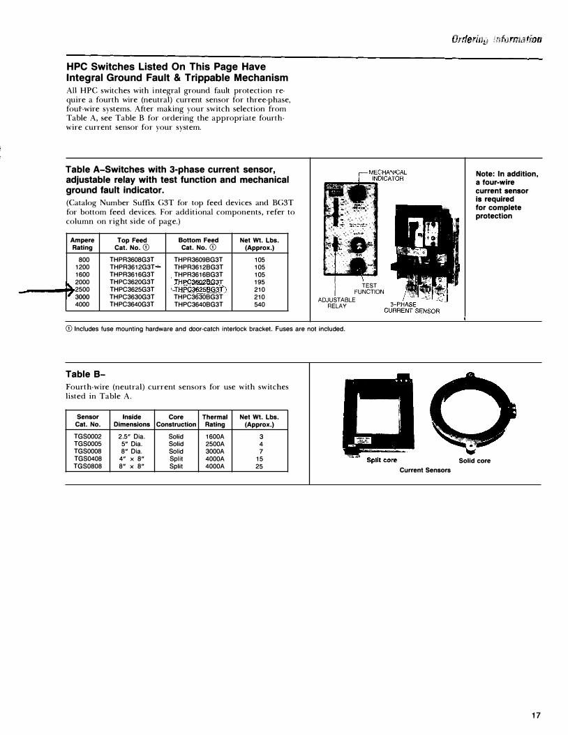
HPC Switches Listed On This Page Have Integral Ground Fault & Trippable Mechanism All HPC switches with integral ground fault protection require a fourth wire (neutral) current sensor for three-phase, four-wire systems. After making your switch selection from Table A, see Table B for ordering the appropriate fourthwire current sensor for your system.
Table A-Switches with 3-phase current sensor, adjustable relay with test function and mechanical ground fault indicator.
(Catalog Number Suffix G3T for top feed devices and BG3T for bottom feed devices. For additional components, refer to column on right side of page.)
Ampere Top Feed Bottom Feed Net Wt. Lbs. Rating Cat. No. CD Cat. No. CD (Approx.)
800 THPR3608G3T THPR3609BG3T 105 1200 THPR3612G3T"'- THPR3612BG3T 105 1600 THPR3616G3T , THPR3616BG3T 105 � 2000 THPC3620G3T J:HPC3602BG3T 195 2500 THPC3625G3T (.:rHf'Q_�® 210
I' 3ooo THPC3630G3T THPC3630BG3T 210 4000 THPC3640G3T THPC3640BG3T 540
TEST FUNCTION
ADJUSTABLE RELAY
CD Includes fuse mounting hardware and door-catch interlock bracket. Fuses are not included.
Table B-
Fourth-wire (neutral) current sensors for use with switches listed in Table A.
Sensor Inside Core Thermal Net Wt. Lbs. Cat. No. Dimensions Construction Rating (Approx.)
TGS0002 2.5" Dia. Solid 1600A 3 TGS0005 5" Dia. Solid 2500A 4 TGS0008 8" Dia. Solid 3000A 7 TGS0408 4" X 8" Split 4000A 15 TGS0808 8" X 8" Split 4000A 25
...
• ---
Current Sensors
Note: In addition, a four-wire current sensor is required for complete protection
Solid core
17

For Swithces Without Integral Ground Fault Protection
Table C-Switches with electric trip for use with Ground Break® components or for remote tripping application.
(Catalog Number Suffix ET l for Top Feed Devices and BETl for Bottom Feed Devices.)
Application
For resistance-grounded systems or where zone selective interlocking is required, electric trip HPC switches with Ground Break system components are recommended.
Requires 1 20 or 240V ac control power. For 480V ac operation use suffix ET2 or BET2 in place of ETl or BETl .
Ampere Top Feed Bottom Feed New Weight Lbs. Rating Cat. No. Q) ® Cat. No. Q) ® (Approx.)
800 THPR3608ET1 TH PR3608BET 1 75 1200 THPR3612ET1 THPR3612BET1 80 1600 THPR3616ET1 THPR3616BET1 80 2000 THPC3620ET1 THPC3620BET1 165 2500 THPC3625ET1 THPC3625BET1 180 3000 THPC3630ET1 THPC3630BET1 180 4000 THPC3640ET1 THPC3640BET1 429
Table 0-Manual Operation
HPC switches, manually operated, for feeder disconnects not requiring ground fault protection or remote tripping.
Ampere Top Feed Bottom Feed Net Weight Lbs. Rating Cat. No. Q) Cat. No. Q) (Approx.)
800 THPR3608 THPR3608B 75 1200 THPR3612 THPR3612B 80 1600 THPR3616 THPR3616B 80 2000 THPC3620 THPC3620B 165 2500 THPC3625 THPC3625B 180 3000 THPC3630 THPC3630B 180 4000 THPC3640 THPC3640B 429
Q) Includes fuse mounting hardware and door-catch interlock bracket. Fuses not included.
HPC with electric trip.
HPC manually operated
®Electric trip switch (suffix ET1 or BET1) requires 120 or 240 volts ac control power. For 480 volts ac operation, change switch Catalog Number suffix to ET2 (top feed) or BET2 (bottom feed).
18

The following UL listed accessories are available for use with 800-4000A HPC high pressure contact switches as indicated:
Internal Accessories Blown fuse protector Auxiliary switch elements
External Accessories Provision for Kirk Key Bus connection adapter Lug kits
Blown-fuse Protector Factory installed only. Provides single-phase protecton by tripping switch when a fuse blows or when switch is closed with a blown fuse or no fuse installed. Suitable for system voltage of 208 to 600Vac. Mounted internally. Does not provide protection of single-phasing of the power source.
Switch Ampere Rating Single-phase Protector
Catalog Number
800-1600A 2000-4000A
Auxiliary Switch
THPRFP THPCFP
Factory installed only-mounts internally. Provides remote indication of main contact position.
Switch elements are form "C", single-pole, double-throw. Leads are connected to externally mounted terminal block. Order one terminal block THPCB 1 for one or two switches; order two THPCBl for three or four switches. Specify and price switches and terminal blocks separately.
Switch element ratings: XI ampere at 250V de; Y2 ampere at 1 25V de; 6 ampere at 240V ac.
No. Of Switch Elements
1 2 3 4
Auxiliary Switch Catalog Number
For 800-1600A Swiches
TPAS2AB1L TPAS2AB2L TPAS1AB3L TPAS2AB4L
For 2000-4000A Switches
TSAS2AB1R TSAS2AB2R TSAS2AB3R TSAS2AB4R
Lug Kits-800-1 600A Switches Field-installed only. Kits consist of terminal adapter strap(s) and hardware for line or load end and do not include lugs. Choice of lug kits must be ordered separately from the table below.
For Use With Terminal Adapter
Cat. No. Lug Kits (CU-AL)
Switch Ampere
Adapter Cat. No. CD (1) #2-SOOMCM (1) 3/0-SOOMCM CU
Rating (2) #1/0-250MCM (1) 250-BOOMCM AL
800 THPCLUGA08 TPLUG106 TPLUG108
1200 TPLUGA16 ...... ... TPLUG108
1600 TPLUGA16 . . . . ..... TPLUG108
Max. Lugs Per Pole Line Or
Load End
3
6
6
T T
CD :n -< 0
CD ::::;; m CD ::::;; r- I r- r- :n z r- )> m c =i 0 0 0 � m m ::::;; :>\ r- I r- r- r- r- m =i m m m )> )> )> m m 0 0 )> )> 0 0 0 r-m )> O_j
Blown fuse protector
Auxiliary switch
0 0 0 0 .o
0 0
SOOA lug adapter
Without Terminal Adapter
Direct Mounting Lugs-Use Without Adpater
(4) 300-750MCM CU or (3) 300-750MCM CU, (4) 300-SOOMCM AL (3) 300-SOOMCM AL
Line Only Load Only
THPLUG308 . . . . . . . . . ....... ..
. ..... . . . TPLUG408 THPCLUG408
. . ..... .. TPLUG408 THPCLUG408
G) Also suitable for use with Anderson Versa-Crimp® Type VCEL, Cat. No's. VCEL-050-12H1 or VCEL-075-12H1.
19

Lug Kits-2000-4000A Switches
Field installed only. To terminate line and load cables. Must be used in conjunction with 2000-4000A bus·connection adaptor listed below.
Each lug kit includes lugs, straps and hardware for three· phase line or load connections. Each cable lug accommodates 1 -3/0 CU or 250MCM AL to 800MCM CU-AL. The table below indicates number of lugs per phase. Accepts Anderson Versa Crimp® when lugs are remolded from straps.
Ampere Rating Catalog Number No. Of Lugs
Per Phase
2000 TSLUG20 6 2500 TSLUG25 7 3000 TSLUG30 9 4000 TSLUG40 11
Bus-connection Adpator
Field installed only. May be used to adapt line and load ter· minals of switch to vertical or horizontal bus arrangements, or to other bus configurations. These required for line or load connections on three·phase bus.
Switch Ampere Rating
BOO 1200-1600
2000 2500 3000
4000
Bus-connection Adaptor Catalog Number
THPCOBFCA TP16FCA TS20FCA TS25FCA TS30FCA {(5) TS40FCA
(1) TS40LFCA
Provison For Customer Installation Of Key Interlock
Switch Ampere Rating Catalog Number No. Of Poles
BOO } ( '""" 1200
TPK01BCD 1
1600 TPK02 2 TPK03 3 '�l u 2500
THPCPGL 3000 4000
CD Provison Only-Requires customer to supply Kirk Key Interlock, Type F. Key removable with bolt extended. Bolt flush when withdrawn. Use only with bottom feed B00-1600A.
20
c�;r=:J 'I
�>
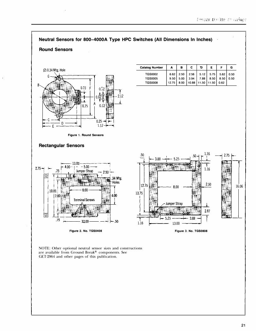
Neutral Sensors for 800-4000A Type HPC Switches (All Dimensions In Inches)
B
Round Sensors
(2) 0.34 Mtg. Hole G--��---------.
0.25 -l f-.1 1.12--H
Figure 1. Round Sensors
Rectangular Sensors
Catalog Number A B
TGS0002 6.62 2.50
TGS0005 9.50 5.00
TGS0008 12.75 8.00
.50
Tl�l-5.25 1.16 1--- 13.00
c 'D
2.56 5.12
3.94 7.88 10.88 11.50
Figure 2. No. TGS0408 Figure 3. No. TGS0808
NOTE: Other optional neutral sensor sizes and constructions are available from Ground Break® components. See GET-2964 and other pages of this publication.
E F G
5.75 5.62 0.50
8.50 8.50 0.50 11.50 0.62
-j 2.75 t-
1 16 .06
21

Ground Fault Protective Products for Resistance Or Solid-state ground ac Electrical Systems
Description The Ground Break system of solid-state ground fault signaling relays, sensors and monitor panels can be used with electric trip HPC switches. These components can be combined to provide zone-selective interlocking for optimum system selectivity. The built-in memory function integrates intermittent faults with time providing protection against low-level arcing faults. The components which comprise a complete system are :
Current Sensor
Solid- or split-core construction for easy installation, includes an integral test winding for checkout of the com plete system. A large variety of window sizes are available.
Solid-state Relay
Used in conjunction with devices having an electric trip, or shunt trip, this relay will sense ground currents and cause the interruptor to open when these currents reach a preselected value for a preselected length of time. Optional zone selective interlocking is available for a fully coordinated system. This type of relay initiates an instantaneous trip when a fault occurs in its own zone. In addition it will block upstream zone selective relays for a preset delay time to allow the down stream breaker to clear the fault.
Ground Break Components
Adjustable Solid-state Relays
Trip Range Zone
Monitor Panel
Provides a ground-fault indicator, control power indicator and TEST and RESET buttons. The control circuitry offers the ability to test the complete Ground Break system with or without tripping the interruptor.
Features • Instantaneous zone-selective trip for
optimum system coordination and protection.
• Heavy-duty design permits direct operation of electric trip and alarm devices without external relays.
• Dependable operation-solid-state relay, cast insulated sensor.
• Two NO contacts, one of which is electrically isolated from the electronic device.
• Output contact rating 5 amperes continuous, 30 amperes inrush, up to 240V ac or 1 25V de.
• Adjustable pickup and delay time.
• Spl it-core sensors easily adapt to new or existing equipment.
• Memory function for system protection against intermittent arcing faults.
How To Order
Specify appropriate relay, sensor and monitor panel catalog number from Table below. For additional application information, refer to GET-2964.
Monitor PanelsCD
With Standard With GF
Control Amperes Selective Indicator
Mechanical Window Voltage
Light Target GF Diameter
Catalog Catalog Indicator (Inches) LO HI Number Number Cat. No.
Cat. No.
120 Vac 5 60 TGSR06 TGSR06Z TGSMP TGSMA 2112 5
125 Vdc 5 60 TGSR06 TGSR06Z TGSMPA 8 48 Vdc 5 60 TGSR06B TGSR06BZ TGSMPB 32 Vdc 5 60 TGSR06C TGSR06CZ TGSMPC 4 X 8 24 Vdc 5 60 TGSR06D TGSR06DZ TGSMPD 4 X 18
4 X 24 4 X 32
120 Vac 100 1200 TGSR12 TGSR12Z TGSMP TGSMA 8 X 8 125 Vdc 100 1200 TGSR12 TGSR12Z TGSMPA 8 X 10
48 Vdc 100 1200 TGSR12B TGSR12BZ TGSMPB 8 X 18 32 Vdc 100 1200 TGSR12C TGSR12CZ TGSMPC 8 X 24 24 Vdc 100 1200 TGSR12D TGSR12DZ TGSMPD 8 X 32
8 X 38 11 X 13
CD Monitor panel requires 120 volts ac for test system function.
22
Figure 4. Monitor Panel
Figure 5. Solid-state Relay
Figure 6. Current Sensors
Current Sensors
Catalog Test Number
Construction Winding
TGS0002 Round-TGS0005 Yes
TGS0008 Solid Core
TGS0408 TGS0418 TGS0424 TGS0432 TGS0808 TGS0810 Rectangular Yes TGS0818 Split Core TGS0824 TGS0832 TGS0838 TGS1113

All Dimensions Are In Inches
Relay and Monitor Panel
Figure 1 . Relay
Round And Rectangular Sensors These sensors are suitable for use with integral ground fault HPC switches as the neutral current transformer when the system is single-phase, three-wire, or threephase, four-wire.
Dimensions Clearance of 1" must be maintained between all conductors and inside surfaces of the sensors, except as noted in Figures 5 and 8. Clearance reduced to 'h inch for TGS0005 and to zero for TGS0002.
Round Sensors (Figure 3)
Cat. No. A B c D E
TGS0002 6.62 2.50 2.56 5.12 5.75
TGS0005 9.50 5.00 3.94 7.88 8.50
TGS0008 12.75 8.00 5.44 10.88 11.50
Rectangular Sensors (Figures 4, 5, 6, 7, & 8)
Catalog No. Of
Mtg. A B Number
Holes
TGS0408 4 . . . .. ..... TGS0418 6 23.00 18.00 TGS0424 6 ;29.00 24.00 TGS0432 10 37.00 32.00 TGS0808 4 ..... ..... TGS0818 6 23.00 18.00 TGS0824 6 ;29.00 24.00 TGS0832 10 37.00 32.00 TGS0838 10 43.00 38.00 TGS1113 4 ..... . ....
F
5.62
8.50
11.50
c
. .... 2.12 5.12 0.62 .....
2.12 5.12 0.62 3.62 .....
G
0.50 0.50
0.62
Fig. No.
7 6 6 6 5 5 5 5 5 8
Figure 3. Round Sensor
Figure 5. Rectangular Sensor
Figure 7. No. TGS0408
Figure 2. Monitor Panel (flush-mounted)
Figure 4. No. TGS0808
Mtg. holes for TGS0432
Mtg. holes for TGS0418 TGS0424
Figure 6. Rectangular Sensor
Figure 8. No. TGS1113
23

The sketches and tables below provide a quick reference for overall sizes of all switches, 800-4000 amperes. More
ENCLOSURE FRONT
Figure 1.
Overall Estimating Dimensions-Figure 1 .
Switch
Ampere A B c D E F Rating CD
BOO 24.31 18.00 8.66 7.69 · · · · · · · · · · 4.96 1200 } 1600
26.72 18.00 8.66 7.69 4.76
2000 } 2500 36.00 19.2sCD 9.38 8.25 15.56 3000
4000 40.00® 22.380 11.12 9.24 12.75 (80) 18.19 7.75 (A&C0)
Application Information
Switch Ampere Rating Data
8j)0-1600A 2000- 2500A
Outline 139C4219
139C4114 139C4114 Drawing Sh. 2 Sh. 3
Approx. as lbs. 190 lbs. 205 lbs.
Shpg. Wt.® 115 lbs. 220 lbs. 235 lbs.
Approx. ?Sibs. 1651bs. 180 lbs. Net.Wt. ® 105 lbs. 195 lbs. 210 lbs.
Connectors THPCOBFCA® TS20FCA TS25FCA Cat. No. TP16FCA® (Optional) (Optional)
CD For Cat. No's. with suffix "B" (bottom feed), invert drawing.
® With integral ground fault, length is 42 inches.
0 With integral ground fault, overall width is 25.38 inches.
3000A
139C4114 Sh. 3
205 lbs.
235 lbs.
180 lbs. 210 lbs.
TS30FCA (Optional)
4000A
139C4114 Sh. 6
429 lbs.
464 lbs.
505 lbs. 540 lbs.
1-TS40LFCA 5-TS40FCA0
0 Included in price of 4000 A switch, but must be ordered separately.
®Ventilating openings can be in alternate locations but must provide equivalent ventilating area.
24
detailed dimensional information IS contained m the outlines that follow through page 28.
FROM LINE TO GROUND \)R TO INSULATION.
"F"_J L__ SWITCH _j L "F" l I WIDTH l I
MIN. HEIGHT
"C"
WIDTH "D" I MOUNTING
:0 "B"
I--MIN. ----j DEPTH "E" BASE MTG. BOLTS
(800-3000A HPC Only)
Figure 2.
Enclosure Dimensions, Volume And Ventialtion Requirements-Figure 2
Switch Ampere Rating
Data
BOOA 1200-
2000A 2500A 3000A 1600A
Min. Volume 8,400 11,100 28,000 28,000 30,000 (Cubic Inches)
"A" Min. Ventilation
23 63 63 172 172 Top and Bottom® (Square Inches)
"B" Min. Line to Grd. 2 2 2 2 2
(Inches)
"C" Min. Height 28 30 40 40 40
(Inches)
"D" Min. Line to Grd. 25 25 25 25 25
(Inches)
"E" Mounting Depth 8.66 8.66 9.38 9.38 9.38
(Inches)
"F" Min. to Gnd.
3.5 3.5 3 3 3 or Insulation (Inches)
®Second wt with integral ground-fault.
CD Overall width of 3000A switch with integral ground-fault is 23.75 inches.
® BOOA only (optional).
® 1200 and 1600A (optional).
4000A
54,650
189
9
52
30
11.12
3

Dimensions (for estimating only) 800-1 600 Amperes
NOTE "A"-To CLOSE switch, actuate handle once 1 20° counterclockwise. To OPEN switch, push OFF button or turn handle counterclockwise.
NOTE "B"-Typical 1kl 3 bolt for fuse connections supplied with switch.
NOTE "C"-Integral ground fault sensor, supplied with ground fault accessory using Cat. No. suffixes G3T and BG3T. Extends as shown.
NOTE "D"-Three (3) holes required for ground fault push buttons and target accessory with Cat. No. suffix ending in "T".
Switches with integral ground fault (Catalog No's. with suffix "G3T" or "BG3T")
s.oo--j .39 I 1-_i_<±>T ...L<±>
I 1.50 I 3.63 T <±>
-®_i_ 3.63 1 ' 1.50 _L
-fo,T -ft.T L I (3) 1.12 OIA.(MJN.) J I .39 HOLES REQ'D IN COVER FOR GROUND FAULT JI()ICATOR!. TEST BUTTONS
"Line-Top" Devices (Suffix G3T)
"Line-Bottom" Devices (Suffix BG3T)
HPC SWITCH ""AA"" BOOA 2.50
1200A 3.38 1 600A 3.38
Panelboard Door Cut-out for Top Feed Devices
Front Details
Panelboard Door Cut-out for Bottom Feed Devices
Front Detail
For Complete Details Order Outline Drawing
1 39C421 9-Sheet 1
25

26
Dimensions (for estimating only) 2000 Amperes
Top Feed
MOUNTIIIG , st.ll:FACE J
:\OTE "A"-To CLOSE switch, actuate handle 3 times 1 20° counterclockwise. To OPE:\ switch, push OFF button or turn handle counterclockwise.
:'\IOTE "B"-Typical 'l2 - 1 3 bolt for fuse connections sup· plied with switch .
! !
NOTE "C"-Integral ground fault sensor, supplied with ground fault accessory using Cat. No. suffixes G3T and BG3T. Extends as shown.
NOTE "D" -Three (3) holes required for ground fault push buttons and target accessory with Cat. No. suffix ending in "T".
For Complete Details Order Outline Drawing
1 39C41 1 4-Sheet 2
INTERLOCK BRACKET WELDED TO DOOR .
Bottom Feed
NOTE : THIS IS FOR 'LINE BOTTOM ' DEVICES WITH"B' SUFFIX .
LINE SHIELD
Panelboard Door Cut-out for Top Feed Devices
1.50
Front Detials (Invert for Bottom Feed Devices
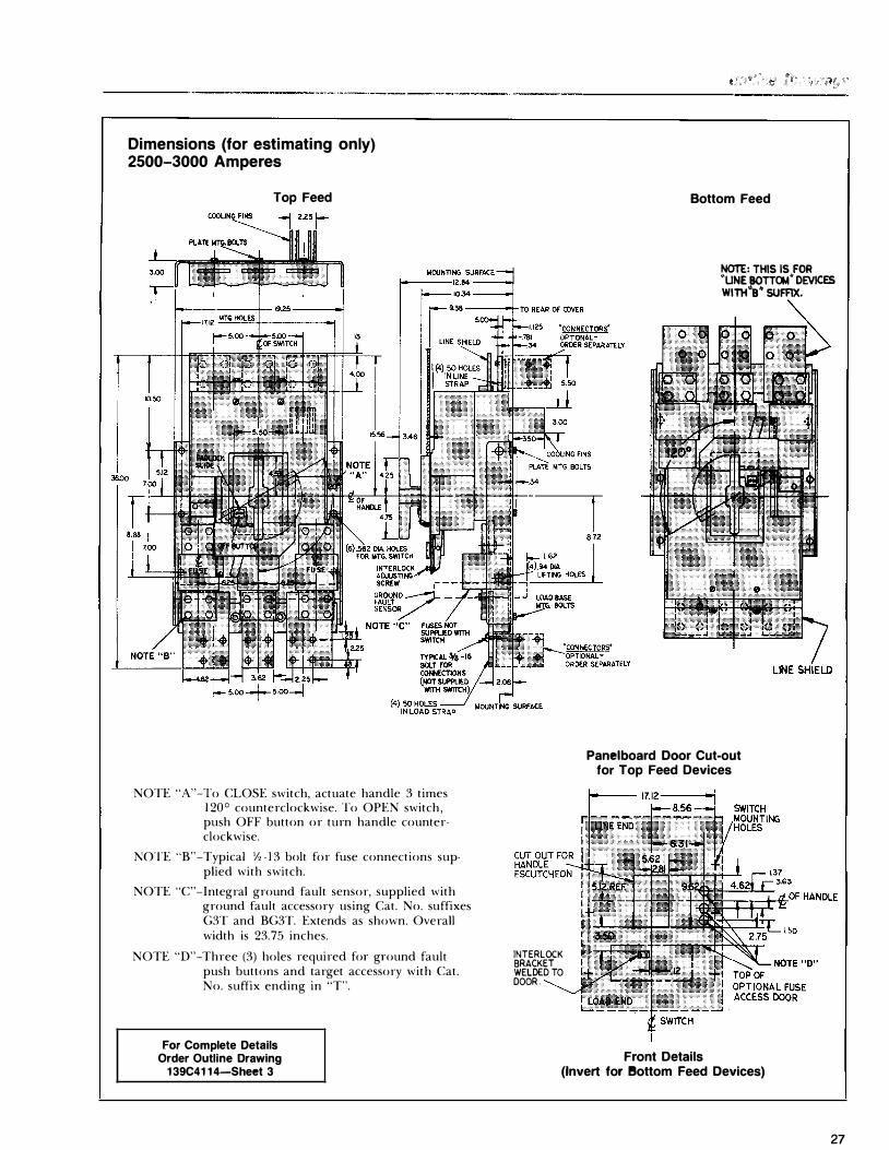
Dimensions (for estimating only) 2500-3000 Amperes
Top Feed
NOTE "A"-To CLOSE switch, actuate handle 3 times 1 20° counterclockwise. To OPEN switch, push OFF button or turn handle counter· clockwise.
NOTE "B"-Typical Yz · l 3 bolt for fuse connections sup· plied with switch.
NOTE "C"-Integral ground fault sensor, supplied with ground fault accessory using Cat. No. suffixes G3T and BG3T. Extends as shown. Overall width is 23.75 inches.
NOTE "D" -Three (3) holes required for ground fault push buttons and target accessory with Cat. No. suffix ending in "T".
For Complete Details Order Outline Drawing
1 39C41 1 4-Sheet 3
INTERLOCK BRACKET WELDED TO DOOR .
Bottom Feed
NOTE: THIS IS FOR ''UNE BOTT�" DEVICES Wlnt"s• SUFAX.
Panelboard Door Cut-out for Top Feed Devices
Front Details (Invert for l!lottom Feed Devices)
27
28
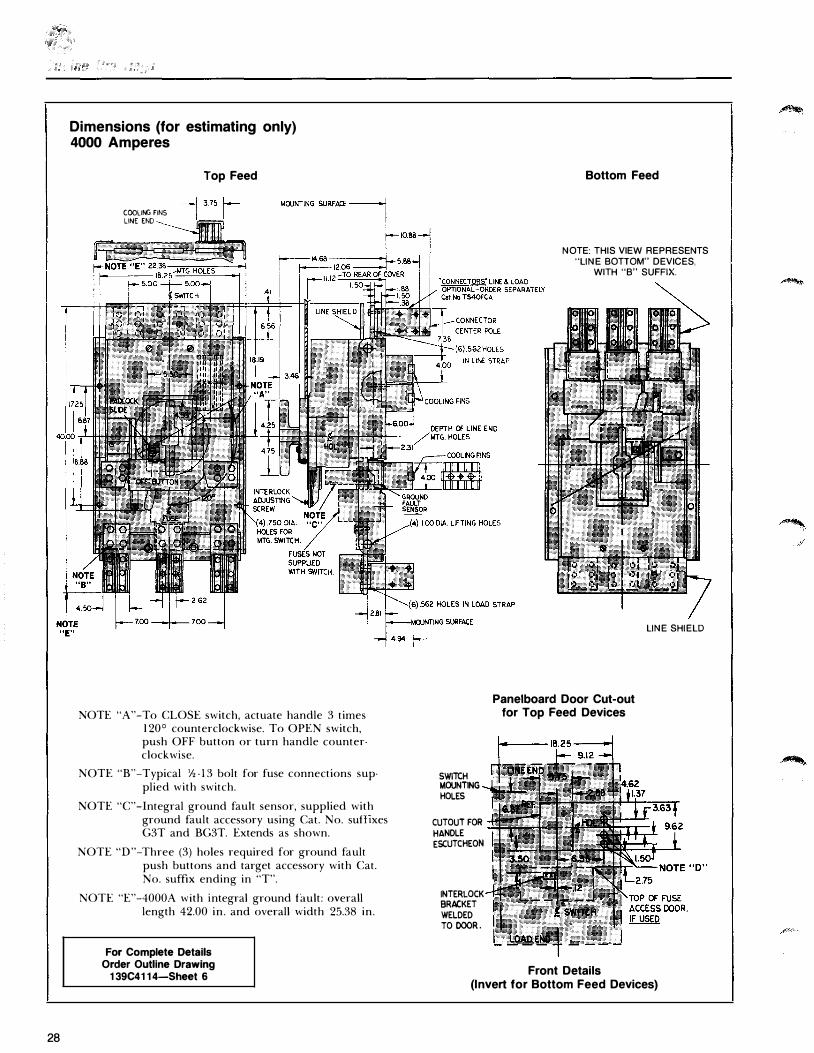
Dimensions (for estimating only) 4000 Amperes
COOLING FINS LINE END
Top Feed
NOTE "A"-To CLOSE switch, actuate handle 3 times 1 20° counterclockwise. To OPEN switch, push OFF button or turn handle counterclockwise.
NOTE "B"-Typical Y2 - 13 bolt for fuse connections supplied with switch.
NOTE "C"-Integral ground fault sensor, supplied with ground fault accessory using Cat. No. suflixes G3T and BG3T. Extends as shown.
NOTE "D"-Three (3) holes required for ground fault push buttons and target accessory with Cat. No. suffix ending in "T".
NOTE "E"-4000A with integral ground fault: overall length 42.00 in . and overall width 25.38 in.
For Complete Details Order Outline Drawing
1 39C41 1 4-Sheet 6
SWITCH MOUNTING HOLES
CUTOUT FOR HANDLE ESCUTCHEON
INTERLOCK BRACKET WELDED TO DOOR .
Bottom Feed
NOTE: THIS VIEW REPRESENTS "LINE BOTIOM" DEVICES,
WITH "B" SUFFIX.
Panelboard Door Cut-out for Top Feed Devices
Front Details
LINE SHIELD
(Invert for Bottom Feed Devices)

Type HPC Switches With and Without Integral Ground Fault Protection
Description Rating Remarks
Ampere Ratings 800, 1 200, 1 600, 2000, 2500, 3000, and 4000A.
Voltage Ratings 600V ac Maximum, 60 Hz. Can be used on any ac system up to 600V maximum.
Fusing Rated or smaller size Class L fuses. All switches can be underfused down to the lowest rating Class L fuse (60 1 A).
Shot Circuit Rating All switches are suitable for use on HPC switches have the same maximum circuits capable of delivering not short-circuit capability as UL Listed more than 200,000 rms amperes Class L fuses. symmetrical fault current at 600V ac maximum, ! -phase or 3-phase, .20 power factor minimum
Switch Interrupting Capability All switches will safely make and UL requires breaking 1 2X current on break 1 2 times rated current at devices for Class 1 ground fault use 600V ac, 3-phase, for a maximum of only. three interruptions.
Short Circuit Withstandability, Switch Test Fuse At 1 00KA I2t (amp.2-seconds) values based on actual Amperes-Squared-Seconds Ampere
pt X 1 03 I peak UL test-fuse lot certification at 1 00,000 Rating
800-1600 22,500 100,000 rms symmetrical, 600V ac, single-phase,
2000 36,880 1 23,000 .2 p.f. Although switch is UL listed at
2500-3000 1 1 2,000 1 88,000 200KA, prior to June 1 975 all fuse cer-4000 188,000 225,000 tificaktion tests were at 1 00KA.
Coordination of Fuse lpeak and Fuse & Fuse lp Switch Ip is that short-circuit current which Switch Interrupting Capability Switch (Approx.)
Interrupting Ratio would cause the fuse to melt in approxi-on Low-Level Faults
Rating Capability mately .25 seconds. The .25 second time 800 8,000 1 9,200 24 is representative of the fastest one can
1 200 9,500 1 9,200 1 6 1 600 1 4,000 1 9,200 1 2 turn o n HPC switch and quickly turn off 2000 1 9,000 30,000 1 5 with push-to-trip button and the fuse has 2500 24,000 30,000 1 2 not yet cleared. Values of current are for 3000 28,000 52,000 1 8 4000 40,000 52,000 1 3 time-delay Class L fuses.
29

Only For Switches With Integral Fault Protection
Description Rating Remarks
Current Transformer 800: 1 (Sensor) Ration
Integral Test Winding Ratio 700: 1
Integral Ground Fault Thermal rating of integrally mounted Thermal Rating 3-phase sensors is equal to the full,
continuous ampere rating of the switch . This current is the maximum continuous current that will not overheat the sensor.
Maximum Ground Fault Current 40,000 Amperes for 0.5 seconds. High I2t withstandability assures no dam· Rating 200,000 Amperes for 0.008 seconds. age to integral ground fault components.
Dielectric Windings to mgt. bushing-1 .5 kV Winding to CT window surface-2.2 kV Mounting bushings to CT window surface-2.2 k V
Insulation Cast epoxy-all sizes of integral sen- Cast epoxy provides a rugged con-sors and separate Ground Break® struction. fourth wire sensors.
Adjustable Ground Fault 200 to l OOA in six (6) steps, toler- Permits pickup settings to be coordinated Trip Range ance ± 1 0 % , but not exceeding throughout the system.
l 200A when set at l l OOA.
Delay Time Minimum-0.05 seconds. Minimum setting for minimum ground Intermediate-0.2 seconds. fault damage; maximum for greatest Maximum-0.4 seconds. coordination.
Power Dissipation None except during a ground fault. Integral ground fault relay is powered by the actual ground fault.
Control Power for l 20V ac source, 20 volt-amperes, min. Simulates ground fault for system check Ground Fault Trip Check Customer must provide control power.
Fourth Wire Neutral Sensor Sensor Inside These sensors must be ordered separately Construction Catalog No. Dimensions Type from switch. They are mounted by
TGS0002 2.5" dia. Solid Core customer in convenient location and
TGS0005 5" dia. Solid Core wired with # 1 4 AWG minimum wire TGS0008 8" dia. Solid Core size. Run should not exceed 1 00 feet TGS0408 4" X 8" Split Core and wires should not be harnessed with TGS0808 8" X 8" Split Core power conductors.
30

High Pressure Contact Switches (Fused Power Circuit Devices)
High pressure contact switches, GE Type HPC (800-4000A), shall be furnished and installed as indicated on the drawings.
Standards
The HPC switches shall be UL listed in accordance with Underwriters' Laboratories, Inc., Standard for Fused Power Circuit Devices, UL977, and shall bear the listing mark. They shall also be CSA certified.
Function
The HPC switch shall provide overcurrent and short circuit current protection with UL listed high·in terrupting current· limiting Class L fuses and shall be UL listed as suitable for use on circuits capable of delivering up to 200,000 amperes rms symmetrical at 600V ac maximum. The switch and fuses shall be fully coordinated at all current levels, up to and in· eluding the maximum short circuit current.
All HPC switches shall be rated for "making" and "breaking" 1 2X currents at 600V ac for at least three operations.
Construction
Fused power circuit devices shall be butt·type contact con· struction with multiple, spring·loaded main arms and an arc· ing arm per pole. The switch shall be in a molded insulating case and cover having integrally molded interphase partitions.
The HPC switch shall be rated ______ amperes at 600V ac.
UL listed Accessories shall be provided as follows:
- Integral, self·powered ground·fault protection with mechanical ground·fault indicator, test function, adjustable pick·up current and delay time with inverse and constant time characteristics, and phase·current sensor.
- Electric trip for use on ( 1 20) (240) (480) V ac control power.
- Blown·fuse protector.
- Provision for key interlock.
- Auxiliary switches with ( 1 ) (2) (3) (4) single·pole, double· throw elements.
HPC switches, when specified with ground fault protection, shall be Type THP integral ground fault with adjustable pick· up current and adjustable time delay setting. The ground fault system shall be self.powered, and shall not require an external control power source except for test purposes. The ground fault relay shall have an internal memory circuit which integrates intermittent arcing ground faults with time.
For systems requiring zone selective interlocking, HPC elec· tric trip switches and GE Ground·Break® components shall be used.
31

General Electric Company 4 1 Woodford A venue, Plainville, CT 06062
GET-62058 1 189 BLE © 7989 General Electric Company