Embed Size (px)
Citation preview
Tutorial 1
Questions
1. Why is it important to interface the manufacturing engineering requirements
with the design phase as early as possible?
2. What is difference between tolerance and allowance?
3. What is difference between accuracy and precision?
4. Explain how could you determine whether your ordinary bathroom scale is
linear and has good repeat accuracy assuming the scale is analog?
5. What are some unattractive features of destructive methods?
6. What is proof test and what assurances does it provide?
7. What are some factors that should be considered when selecting a
nondestructive testing method?
8. What is primary limitation of a visual inspection?
9. What is the primary materials related limitation of magnetic particle
inspection?
10. Why don’t standard tables exist detailing the natural variability at a given
process, such as rolling, extruding or turning?
11. How does the taguchi approach differ from the typical experimental
approach?
12. What are common reasons for sampling inspection rather than 100%
inspection
Problems
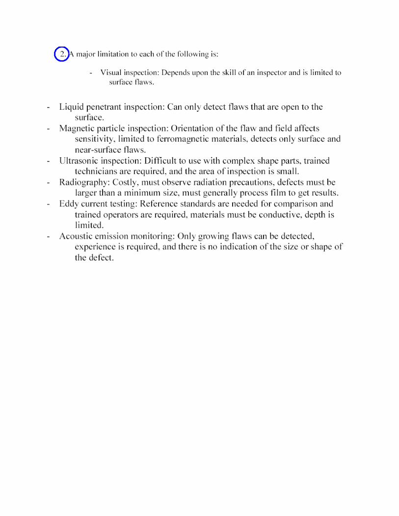
1. For each of the inspection methods listed, cite one major limitation to its use.
a. Visual inspection
b. Liquid penetrant inspection
c. Magnetic particle inspection
d. Ultrasonic inspection
e. Radiography
f. Eddy-current testing
g. Acoustic emission monitoring
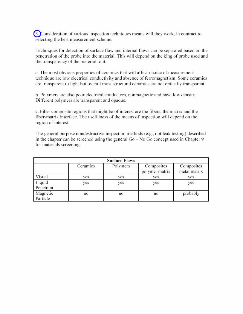
2. Which of the major nondestructive inspection methods might you want to
consider if you want to detect surface flaws and internal flaws in products
made from each of the following materials?
a. Ceramics
b. Polymers
c. Fiber-reinforced composites with (i) polymer matrix and
d. (ii) metal matrix (consider various fiber materials)
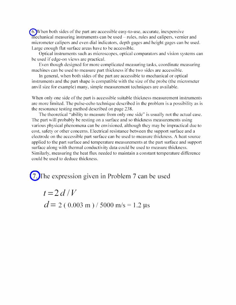
3. The pulse-echo ultrasonic technique can be used to determine the thickness of
a part or structure. By accurately measuring the time it takes for a short
ultrasonic pulse to travel through the thickness of a material, reflect from the
back or inside surface, and return to the transducer, the distance can be
calculated by:
d=Vt/2 where d = thickness of the test piece, V = velocity of sound in the material
being tested t = measured round trip time
What are some alternative means of measuring thickness? Briefly discuss their
relative pros and cons. Consider such features as geometric and material constraints,
and the ability to measure from one side only.
4. If , V for a particular metal is 5000 m/sec and a part made of that material is 3
mm thick, what is the transit time for the pulse to cross the material and
reflect back to the source/receptor? (Note: The transit time is a consideration
in evaluating equipment capabilities and may well influence cost!)
5. Determine the standard deviation and process mean for the data given for flof
ball diameters. A golf ball has a dimpled surface to improve flight accuracy
and distance. Its diameter is specified as 1.68 inches minimum by the
Professional Golf Association. Measurements were made with a 1 to 2 inch
micrometer. Golf balls are made by a process with a natural total tolerance of
6' approximately equal to 0.01 inches with an average size of 1.68 inch.
The data given for the golf balls (See chart below) was for good used golf balls
found on the golf course near one of the author's home. They were separated by
Titleist (TI), Pro Staff (PS), Top Flight (TF), Pinnacle (PI), and Dunlop (DU).

Sample No. Measurements of Diameter Xbar R
1 T1 1.683
1.675
1.682
1.680
1.6800 0.007
2 PS 1.681 1.6805 0.003
1.678
1.68 1
1.682
3 TF 1.676 1.6798 0.006
1.682
1.682
1.679
4 TF 1.677 1.679 0.003
1.680
1.680
1.679
5 TF 1.677 1.677 0.004
1.679
1.679
1.678
6 PI 1.679 1.6800 0.004
1.68 1
1.682
1.678
7 TI 1.678 1.6770 0.003
1.675
1.678
1.677
8 TF 1.681 1.6803 0.001
1.680
1.680
1.68 1
9 DU 1.676 1.6800 0.004
1.679
1.680
1.680
10 PS 1.677 1.6775 0.003
1.680
1.677
1.677
11 TF 1.678 1.6778 0.002
1.677
1.679
1.677
12 TF 1.675 1.6767 0.004
1.677
1.678
1.676

Tutorial 1
Answers
1. The least expensive time to make a change on the design is before the part is
being made. Putting the manufacturing engineering requirements into design
phase helps insure that the part can be economically fabricated.
2. The allowance determines the desired fit between mating part. Tolerance
takes into account the deviations from a desired dimension.
3. To determine the aim of the process one needs the measures of accuracy. To
determine the variability in a process one needs measures of precision.
Accuracy is measured by distribution means and precision is measured by
variances or standard deviations.
4. To determine the repeat accuracy, just step on the scale and step off many
times and take reading . Determining the linearity requires that you have a
set of standard weights which you can load on and load off say 10,50,90,130
etc pounds and plot linear loads verses readings
5. When destructive testing is employed, statistical methods must be used to
determine the probability. If certain test specimens are good, then the entire
production will be good. There always remains some degree of uncertainty
about the quality of the remaining products because they have never been
individually evaluated.
6. In a proof test, a product is subjected to loads of determined magnitude,
generally equal to or greater than the designed capacity. If the part remains
intact, then there is a reason to believe that it will perform adequately in the
absence of abuse of loads in excess of its rated level.
7. In selecting a non destructive method one should consider the advantages
and limitations of various techniques. Some can be performed on only
certain types of materials. Each limited in the type, size and orientation of
the flaws that can detect. Availability of the equipment, the cost of
operation, the need for skilled operators and the availability of a permanent
record are other considerations.
8. Visual inspection is limited to accessible surfaces of a product so no
information is provided relating to the interior structure.
9. Materials must be ferromagnetic in order to be examined by the magnetic
particle technique. Non ferrous metals, ceramics and polymers cannot be
inspected
10. Two identical machine tools doing exactly the same process will have
different amounts of process variability. The individual machines will have
different variability when the work material is changed and when also the
operator is changed. Thus it is necessary to gather data on the specific
machine tool during the process itself.
11. In a typical experimental approach one variable at a time is examined and all
the other variables are kept constant. In the taguchi approach all significant
variables are mixed and varied in the same experiment. The later approach
permits one to find the important interactions between dependent variables
as well as to evaluate the significance of each variable.
12. For 100% inspection
a. Not possible when the test is destructive.
b. Test is expensive compared to the cost of the item when items are
produced in great volumes

Question 5
Standard deviation and process mean for the data given for flof
MECH311
Tutorial 1-2
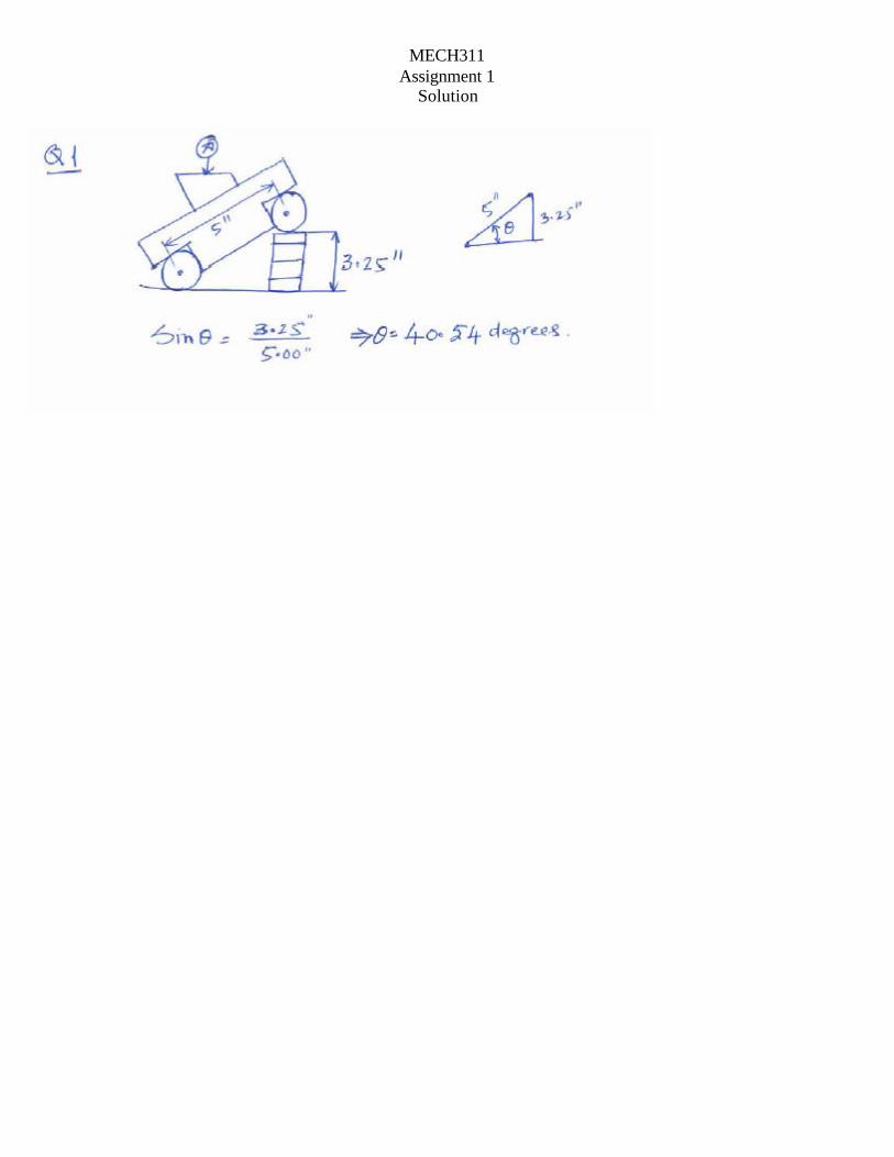
1. Assume you are the in-charge of production where you have to make a quick
angle measurement using a sinebar of 5” size (distance the centers of the
cylinders). When you dialed the indicator for zero reading, the height of the gage
blocks was found to be 3.25inches. What is the angle measured?
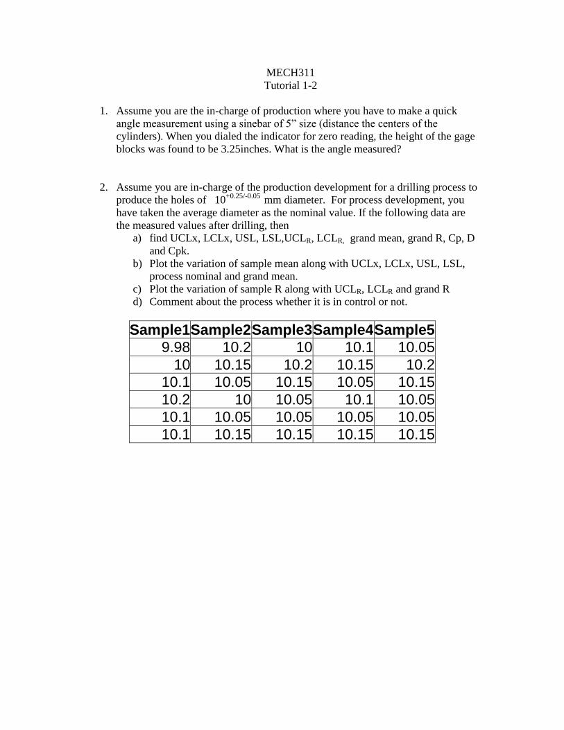
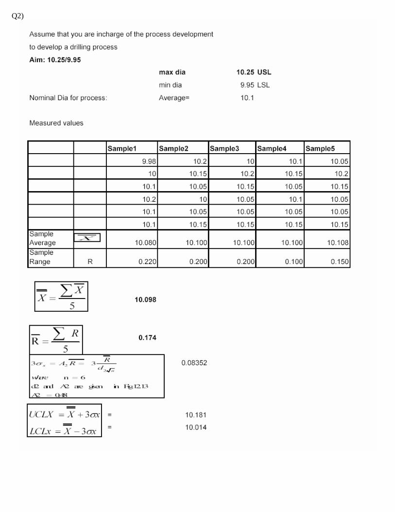
2. Assume you are in-charge of the production development for a drilling process to
produce the holes of 10+0.25/-0.05
mm diameter. For process development, you
have taken the average diameter as the nominal value. If the following data are
the measured values after drilling, then
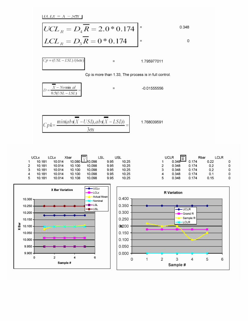
a) find UCLx, LCLx, USL, LSL,UCLR, LCLR, grand mean, grand R, Cp, D
and Cpk.
b) Plot the variation of sample mean along with UCLx, LCLx, USL, LSL,
process nominal and grand mean.
c) Plot the variation of sample R along with UCLR, LCLR and grand R
d) Comment about the process whether it is in control or not.
Sample1 Sample2 Sample3 Sample4 Sample5
9.98 10.2 10 10.1 10.05
10 10.15 10.2 10.15 10.2
10.1 10.05 10.15 10.05 10.15
10.2 10 10.05 10.1 10.05
10.1 10.05 10.05 10.05 10.05
10.1 10.15 10.15 10.15 10.15
MECH311
Assignment 1 Solution
Q2)

TUTORIAL 2
1) Tool work relationship in Turing: A) In turning the work piece rotates and the tool feed, parallel to the axis of rotation. 2) How does form turning differs from ordinary turning: A) In form turning the shape of the tool defines the shape of the surface, and the tool
ss feeded perpendicular to the axis of rotation (radial feed only).
3) Basic difference between facing and part-off A) In the part-off operation the work piece is separated in to two segments. In both
cut off and facing the tool feeds perpendicular to the axis of rotation. (radial feed) 4) What is swing of the lathe A) The swing is the maximum diameter of a work piece that can be rotated in a lathe 5) How is feed specified on a lathe a) in mm/rev 6) Identify the functions of lead screw and feed rod. a) The carriage is driven by either the feed rod or the lead screw .The lead screw
provides positive ratios between carriage movements and spindle rotation (threading). The feed provides automatic axial and radial feeds.
7) What will happen to the work piece when turned, if it is held between centers and
the centers are not exactly in line. A) After the work has been turned ,the surface will be tapered rather than being
cylindrical.
8) Why is it not advisable to hold hot rolled steel stock in a collete? a) The collect holding device is built to accommodate a specific size of the rod with
in tight tolerances. As the hot rolled bar has very course tolerances it will not suitable for collete.

For turning
V=12
** NDΠ surface feet per min(sfpm)
Dept of cut t=2
21 dd −
Cutting Time CT= NfrAL
**
A= over run allowance MRR= volume of metal removed per unit time
= time
vedvolumeremo
For shaping the cutting speed
V= RsNl s
*12**2
Rs=stroke ratio=cutting stroke angle/360 Ns=number of strokes per minute V=cutting speed MRR = volume of metal removed per unit time
MRR= CT
twl **
l=length ; w=width; d=dept of cut, fc: feed/stroke
CT=total length of the cut divided by feed rate =fcNs
W*
184
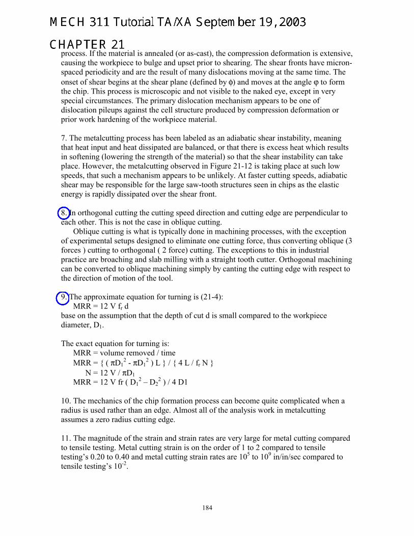
process. If the material is annealed (or as-cast), the compression deformation is extensive, causing the workpiece to bulge and upset prior to shearing. The shear fronts have micron-spaced periodicity and are the result of many dislocations moving at the same time. The onset of shear begins at the shear plane (defined by φ) and moves at the angle ϕ to form the chip. This process is microscopic and not visible to the naked eye, except in very special circumstances. The primary dislocation mechanism appears to be one of dislocation pileups against the cell structure produced by compression deformation or prior work hardening of the workpiece material. 7. The metalcutting process has been labeled as an adiabatic shear instability, meaning that heat input and heat dissipated are balanced, or that there is excess heat which results in softening (lowering the strength of the material) so that the shear instability can take place. However, the metalcutting observed in Figure 21-12 is taking place at such low speeds, that such a mechanism appears to be unlikely. At faster cutting speeds, adiabatic shear may be responsible for the large saw-tooth structures seen in chips as the elastic energy is rapidly dissipated over the shear front. 8. In orthogonal cutting the cutting speed direction and cutting edge are perpendicular to each other. This is not the case in oblique cutting.
Oblique cutting is what is typically done in machining processes, with the exception of experimental setups designed to eliminate one cutting force, thus converting oblique (3 forces ) cutting to orthogonal ( 2 force) cutting. The exceptions to this in industrial practice are broaching and slab milling with a straight tooth cutter. Orthogonal machining can be converted to oblique machining simply by canting the cutting edge with respect to the direction of motion of the tool. 9. The approximate equation for turning is (21-4): MRR = 12 V fr d base on the assumption that the depth of cut d is small compared to the workpiece diameter, D1. The exact equation for turning is: MRR = volume removed / time MRR = { ( πD1
2 - πD12 ) L } / { 4 L / fr N }
N = 12 V / πD1 MRR = 12 V fr ( D1
2 – D22 ) / 4 D1
10. The mechanics of the chip formation process can become quite complicated when a radius is used rather than an edge. Almost all of the analysis work in metalcutting assumes a zero radius cutting edge. 11. The magnitude of the strain and strain rates are very large for metal cutting compared to tensile testing. Metal cutting strain is on the order of 1 to 2 compared to tensile testing’s 0.20 to 0.40 and metal cutting strain rates are 105 to 109 in/in/sec compared to tensile testing’s 10-2.
185
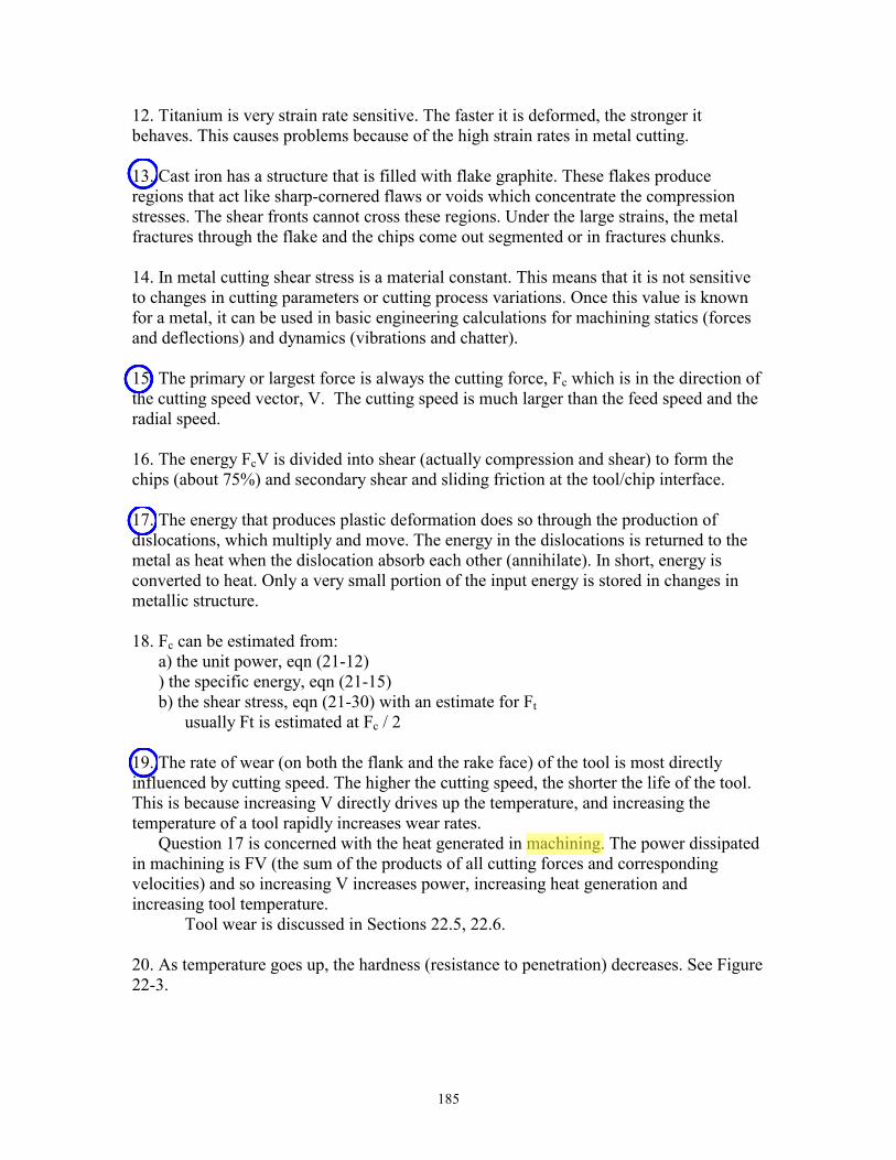
12. Titanium is very strain rate sensitive. The faster it is deformed, the stronger it behaves. This causes problems because of the high strain rates in metal cutting. 13. Cast iron has a structure that is filled with flake graphite. These flakes produce regions that act like sharp-cornered flaws or voids which concentrate the compression stresses. The shear fronts cannot cross these regions. Under the large strains, the metal fractures through the flake and the chips come out segmented or in fractures chunks. 14. In metal cutting shear stress is a material constant. This means that it is not sensitive to changes in cutting parameters or cutting process variations. Once this value is known for a metal, it can be used in basic engineering calculations for machining statics (forces and deflections) and dynamics (vibrations and chatter). 15. The primary or largest force is always the cutting force, Fc which is in the direction of the cutting speed vector, V. The cutting speed is much larger than the feed speed and the radial speed. 16. The energy FcV is divided into shear (actually compression and shear) to form the chips (about 75%) and secondary shear and sliding friction at the tool/chip interface. 17. The energy that produces plastic deformation does so through the production of dislocations, which multiply and move. The energy in the dislocations is returned to the metal as heat when the dislocation absorb each other (annihilate). In short, energy is converted to heat. Only a very small portion of the input energy is stored in changes in metallic structure. 18. Fc can be estimated from: a) the unit power, eqn (21-12) ) the specific energy, eqn (21-15) b) the shear stress, eqn (21-30) with an estimate for Ft usually Ft is estimated at Fc / 2 19. The rate of wear (on both the flank and the rake face) of the tool is most directly influenced by cutting speed. The higher the cutting speed, the shorter the life of the tool. This is because increasing V directly drives up the temperature, and increasing the temperature of a tool rapidly increases wear rates.
Question 17 is concerned with the heat generated in machining. The power dissipated in machining is FV (the sum of the products of all cutting forces and corresponding velocities) and so increasing V increases power, increasing heat generation and increasing tool temperature.
Tool wear is discussed in Sections 22.5, 22.6. 20. As temperature goes up, the hardness (resistance to penetration) decreases. See Figure 22-3.
188
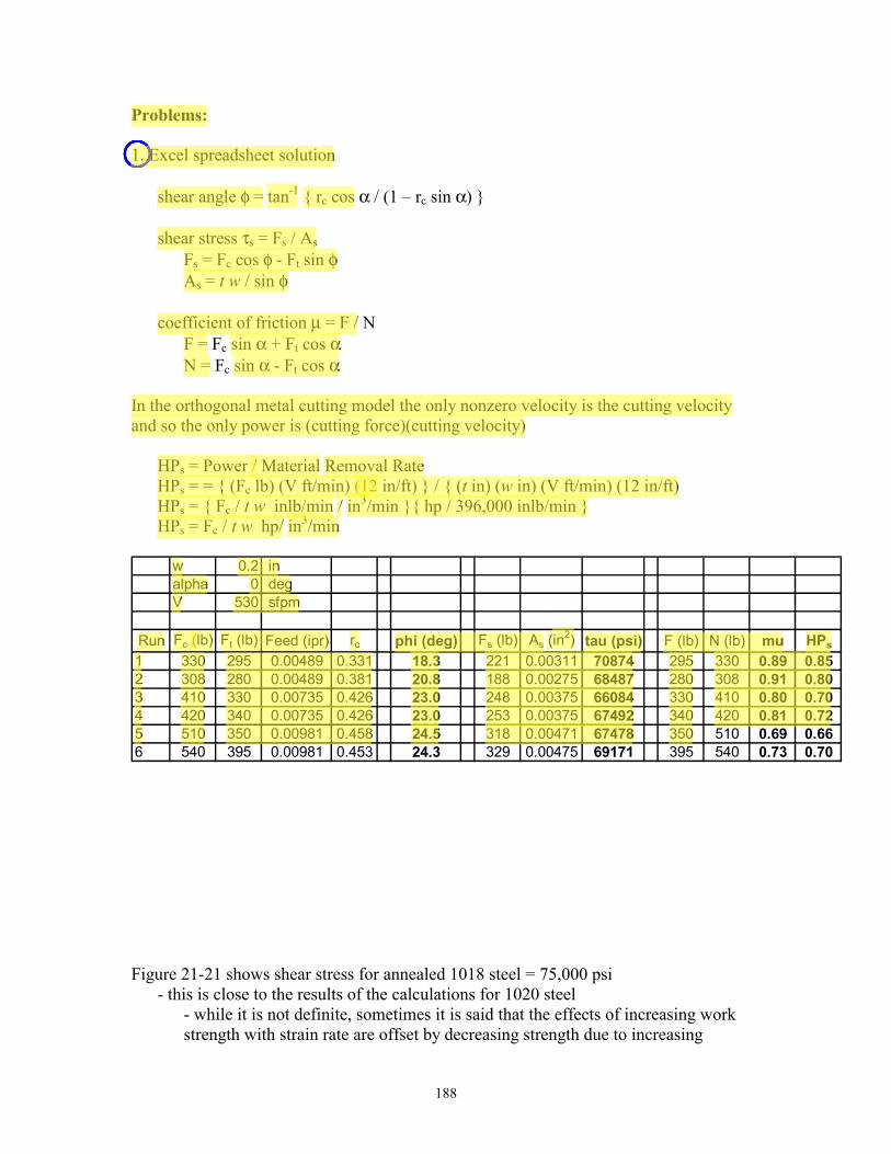
Problems: 1. Excel spreadsheet solution
shear angle φ = tan-1 { rc cos α / (1 – rc sin α) } shear stress τs = Fs / As Fs = Fc cos φ - Ft sin φ As = t w / sin φ coefficient of friction µ = F / N F = Fc sin α + Ft cos α N = Fc sin α - Ft cos α In the orthogonal metal cutting model the only nonzero velocity is the cutting velocity and so the only power is (cutting force)(cutting velocity) HPs = Power / Material Removal Rate HPs = = { (Fc lb) (V ft/min) (12 in/ft) } / { (t in) (w in) (V ft/min) (12 in/ft) HPs = { Fc / t w inlb/min / in3/min }{ hp / 396,000 inlb/min } HPs = Fc / t w hp/ in3/min
w 0.2 inalpha 0 degV 530 sfpm
Run Fc (lb) Ft (lb) Feed (ipr) rc phi (deg) Fs (lb) As (in2) tau (psi) F (lb) N (lb) mu HPs
1 330 295 0.00489 0.331 18.3 221 0.00311 70874 295 330 0.89 0.852 308 280 0.00489 0.381 20.8 188 0.00275 68487 280 308 0.91 0.803 410 330 0.00735 0.426 23.0 248 0.00375 66084 330 410 0.80 0.704 420 340 0.00735 0.426 23.0 253 0.00375 67492 340 420 0.81 0.725 510 350 0.00981 0.458 24.5 318 0.00471 67478 350 510 0.69 0.666 540 395 0.00981 0.453 24.3 329 0.00475 69171 395 540 0.73 0.70
Figure 21-21 shows shear stress for annealed 1018 steel = 75,000 psi - this is close to the results of the calculations for 1020 steel - while it is not definite, sometimes it is said that the effects of increasing work strength with strain rate are offset by decreasing strength due to increasing
189
temperature and the room temperature shear strength of the work can be used for approximate calculations of machining variables. The calculated unit power values of about 0.7 – 0.8 hp/in3/min seem lower than the values in Table 21-3. This is probably due to the simplifications in the orthogonal model of chip formation.
In actual machining there is a feed direction velocity that when multiplied by the feed direction force gives a power dissipation. Calculation of this power with typical values will show that it is negligible with respect to the cutting force power. 2. rc = t / tc
weight density = ρ = weight / volume = Wt / (lc wc tc ) with lc = chip length, wc = chip width, tc = chip thickness tc = Wt / ( lc wc ρ )
rc = t Wt / ( lc wc ρ ) Know Wt, lc, ρ
t is the uncut chip thickness in the orthogonal model and is the feed in conventional turning and should be known since a machining process was run to obtain the chip.
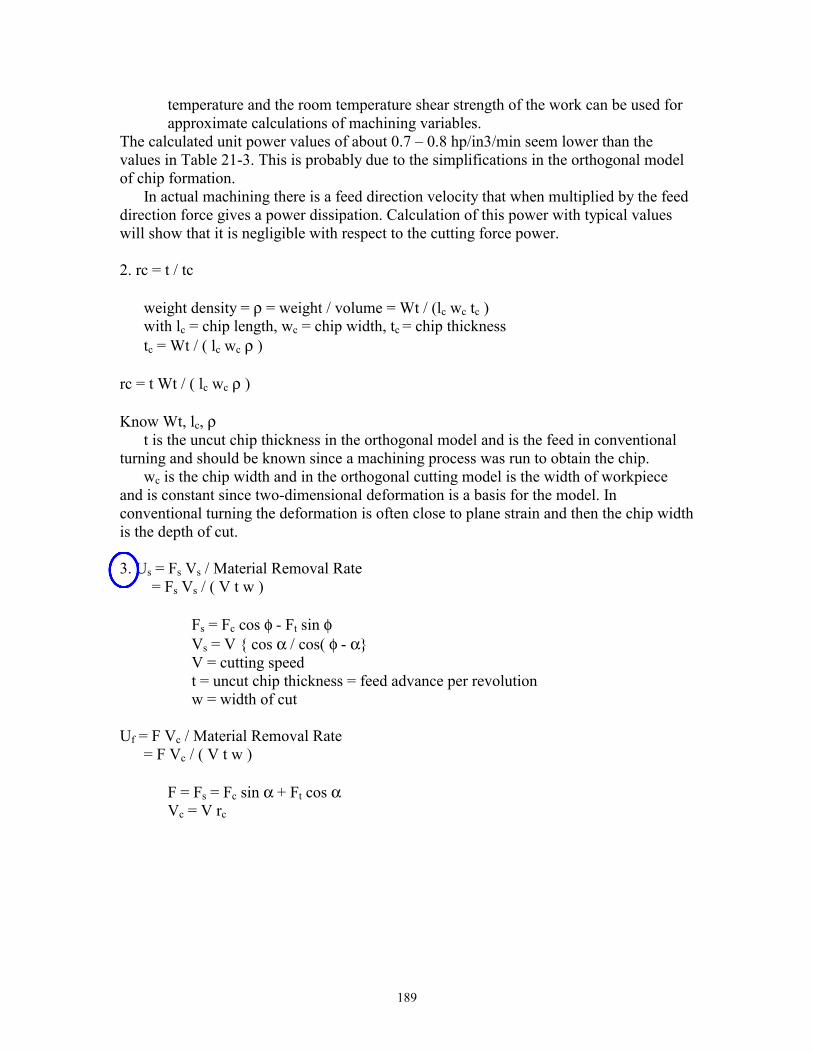
wc is the chip width and in the orthogonal cutting model is the width of workpiece and is constant since two-dimensional deformation is a basis for the model. In conventional turning the deformation is often close to plane strain and then the chip width is the depth of cut. 3. Us = Fs Vs / Material Removal Rate
= Fs Vs / ( V t w )
Fs = Fc cos φ - Ft sin φ Vs = V { cos α / cos( φ - α} V = cutting speed t = uncut chip thickness = feed advance per revolution w = width of cut
Uf = F Vc / Material Removal Rate = F Vc / ( V t w ) F = Fs = Fc sin α + Ft cos α Vc = V rc
190
w 0.2 inalpha 0 degV 530 sfpm
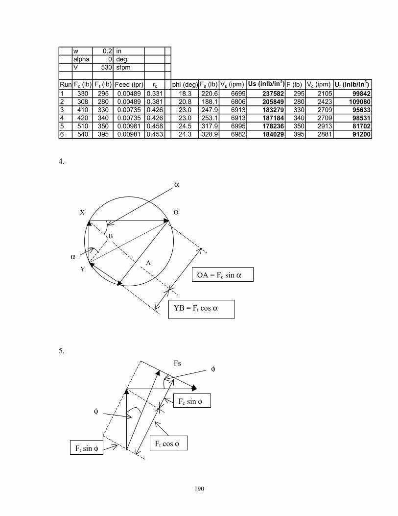
Run Fc (lb) Ft (lb) Feed (ipr) rc phi (deg) Fs (lb) Vs (ipm) Us (inlb/in3) F (lb) Vc (ipm) Uf (inlb/in3)1 330 295 0.00489 0.331 18.3 220.6 6699 237582 295 2105 998422 308 280 0.00489 0.381 20.8 188.1 6806 205849 280 2423 1090803 410 330 0.00735 0.426 23.0 247.9 6913 183279 330 2709 956334 420 340 0.00735 0.426 23.0 253.1 6913 187184 340 2709 985315 510 350 0.00981 0.458 24.5 317.9 6995 178236 350 2913 817026 540 395 0.00981 0.453 24.3 328.9 6982 184029 395 2881 91200 4.
5.
A
B
Y
X O
α
α
OA = Fc sin α
YB = Ft cos α
Fs
Ft cos φ
Fc sin φ
Ft sin φ
φ
φ

192
An alternative problem solution is to use tabulated values of unit machining power such as Table 21-3. For Iconel 700, HP = 1.4 hp/(in3/min) Power = F V in turning P = Fc V + Ft Vfeed + Fr Vr
in turning a straight shaft the radial velocity Vr = 0 the feed direction force Ft is given as Ft / 2 but this component of power will not be included since tool velocity in the feed direction is small compared to the cutting speed. e.g., even at 1000 rpm spindle speed
Vfeed = ( 1000 rev/min )( 0.020 in/rev ) = 20 in/min = 1.7 fpm Power = Fc V P = Fc V = HPs (Material Removal Rate) Fc = P / V MRR = V f d = ( 250 ft/min )( 0.020 in )( 0.250 in )( 12 in/ft ) MRR = 15 in3/min P = { 1.4 hp/(in3/min) } { 15 in3/min } = 21 hp V = 250 ft/min = 3,000 in/min Fc = { 21 hp / 3,000 in/min }{ 396,000 (inlb/min) / hp } = 2,772 lb 8. For rough machining typical ranges of cutting conditions are: Cutting speed, 200 sfpm to 800 sfpm Feed rate, 0.010 ipr to 0.085 ipr Depth of cut, 0.125 in to 0.675 in MRR = 12 V f d MRRmin = 12 ( 200 ft/min ) ( 0.010 in ) ( 0.125 in ) = 3 in3/min MRRmax = 12 ( 800 ) ( 0.085 ) ( 0.675 ) = 550 in3/min For finishing MRRmin = 12 ( 700 ft/min ) ( 0.005 in ) ( 0.0125 ) = 0.525 in3/min MRRmax = 12 ( 1600 ) ( 0.015 ) ( 0.0675 ) = 19.44 in3/min 9. HP = Fc V ftlb/min/ 33,000 ftlb/min/hp V can be obtained from the MRR MRR = 12 V fr d = 550 in3/min V = 550 in3/min { ( 12 ) ( .005 in ) ( 0.675 in ) V = 13,580 ft/min HP = ( 10,000 lb ) (13,500 ft/min ) / 33,000 ftlb/min/hp

193
HP = 4090 hp The 4000 hp value calls for investigation of this unreasonable number. Although the cutting speed seems high it might be possible. The difficulty is probably with the 10,000 lb “measured” force. 10. HPs = Power / MRR Power = 24 hp MRR = 550 in3/min HPs = 0.0436 hp/in3/min Table 21-3, Steel (200 BHN) HPs = 1.50 hp/in3/min & 0.73 hp/in3/min The calculated value is well out of the expected range. Case Study: No case study
194
CHAPTER 22
Review Questions 1. The most important material property for cutting tools is hardness. The tool must be harder than the material being machined to prevent rapid wearing and early failures. 2. Hot hardness is the ability to sustain hardness at elevated temperatures. See Figure 21-22. 3. Impact strength is a material property which reflects the ability of a material to resist sudden impact loads without failure. It is a combination of strength and ductility and is measured by the energy absorbing capability of the material. The two tests used for impact testing are the Charpy and the Izod Impact test. The general term for impact strength is toughness. 4. Many cutting tools experience impacts during routine cutting processes. Interrupted cuts are common in milling. Cutting tools may also impact on hard spots or hard surfaces of a material . 5. RIP is hot isostatic pressing, a powder metallurgy process used to make cutting tools, particularly carbides. See Chap. 16. 6. Primary considerations in tool selection include: What material is going to be machined, what process is going to be used, what are the cutting speeds, feeds, and depths of cut needed, what is the tool material, and what are lubricants going to be used. See Figure 22 - 2 for complete answer. 7. A hard, thin, wear-resistant coating is placed on a tough, strong, tool material. Such composites have good impact strength and good wear resistance. 8. Cermets are a relatively new cutting tool material compared to composed of ceramic materials in a metal binder. See Figure22-10 for a comparison of cermets to other tool materials. 9. CBN is manufactured by the same process used to make diamonds. The powder is used as a coating for carbide blanks in the same way poly-crystalline diamonds are made. CBN powder is sintered and compacted onto a carbide substrate, diced with a laser into segments and the segments brazed into pockets in a standard tungsten carbide insert. The CBN layer is about 0.020 inches thick. 10. F. W. Taylor developed the experiments which lead to the Taylor tool life equation, developed the principles of scientific management and stop watch time study, developed the tool grinder methodology for grinding specific angles on cutting tools, and is considered to be one of the founders of Industrial Engineering. He was also the first
195
United States tennis doubles champion, dispelling the myth he had bad eyesight. 11. Cast cobalt alloy tools would be made by investment casting, due to the high temperatures of the alloys. 12. The compacted powders are compressed into a solid of uniformly fine grains. If cobalt is used as a binder, the solid cobalt dissolves some tungsten carbide, then melts and fills the voids between the carbide grains. This step is called sintering. 13. When the cobalt powders melt and fill the voids between the carbide grains, they "cement" the carbide grains together. This is an old term still used in the cutting tool industry to describe sintered, powder metallurgy tools. 14. The ground inserts are more precise - have less variability from tool insert to tool insert -- so that there is very little difference between tools. This is important when changing tools in automatic equipment or rotating the insert in an indexing tool holder. Therefore, the tool does not have to be reset when the insert tip is changed. Pressed inserts may vary in size as much as .005 inches and may carry this size change into the process. 15. The chip groove is placed on the rake face directly behind cutting edge. Depending upon the depth of cut, the chip groove can make the land in front of the groove act as a controlled contact surface and modify the cutting process. It can cause the shear angle to increase and therefore reduce the power and cutting forces. It can also cause the chips to bend sharply and fracture into short segments which makes chip disposal easier. See Figure 22-9. 16. As shown in Figure 22-13, a groove forms at the outer edge of the cut during the machining of materials with a hard surface or a surface with hard particles in it. The groove is called the depth of cut line or the DCL since it forms at a distance from the cutting edge equal to the depth of cut. 17. a) High speed steel will deflect the most - smallest E b) Ceramic will resist penetration the most - hardest c) High speed steel is the most ductile d) Carbides are the strongest in compression. 18. Tools get hot and expand during machining. Different materials have different coefficients of expansion. The layers are graded with respect to thermal coefficients of expansion to reduce the probability of thermal cracking of the coats. Some layers are also used to promote bonding between the materials. 19. For high-speed steel, black oxide and nitriding are quite common but TiN of RSS is becoming very popular. Coating carbides with TiN and TiC and other materials is popular now using CvD. Aluminum oxide coating is becoming more popular. Ceramics are usually not coated or surface treated.
198
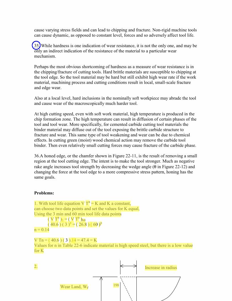
cause varying stress fields and can lead to chipping and fracture. Non-rigid machine tools can cause dynamic, as opposed to constant level, forces and so adversely affect tool life. 35. While hardness is one indication of wear resistance, it is not the only one, and may be only an indirect indication of the resistance of the material to a particular wear mechanism. Perhaps the most obvious shortcoming of hardness as a measure of wear resistance is in the chipping/fracture of cutting tools. Hard brittle materials are susceptible to chipping at the tool edge. So the tool material may be hard but still exhibit high wear rate if the work material, machining process and cutting conditions result in local, small-scale fracture and edge wear. Also at a local level, hard inclusions in the nominally soft workpiece may abrade the tool and cause wear of the macroscopically much harder tool. At high cutting speed, even with soft work material, high temperature is produced in the chip formation zone. The high temperature can result in diffusion of certain phases of the tool and tool wear. More specifically, for cemented carbide cutting tool materials the binder material may diffuse out of the tool exposing the brittle carbide structure to fracture and wear. This same type of tool weakening and wear can be due to chemical effects. In cutting green (moist) wood chemical action may remove the carbide tool binder. Then even relatively small cutting forces may cause fracture of the carbide phase. 36.A honed edge, or the chamfer shown in Figure 22-11, is the result of removing a small region at the tool cutting edge. The intent is to make the tool stronger. Much as negative rake angle increases tool strength by decreasing the wedge angle (θ in Figure 22-12) and changing the force at the tool edge to a more compressive stress pattern, honing has the same goals. Problems: 1. With tool life equation V Tn = K and K a constant, can choose two data points and set the values for K equal, Using the 3 min and 60 min tool life data points ( V Tn )3 = ( V Tn )60 ( 40.6 ) ( 3 )n = ( 26.8 ) ( 60 )n n = 0.14 V Tn = ( 40.6 ) ( 3 ).14 = 47.4 = K Values for n in Table 22-6 indicate material is high speed steel, but there is a low value for K 2.
Wear Land, Wf
Increase in radius
198
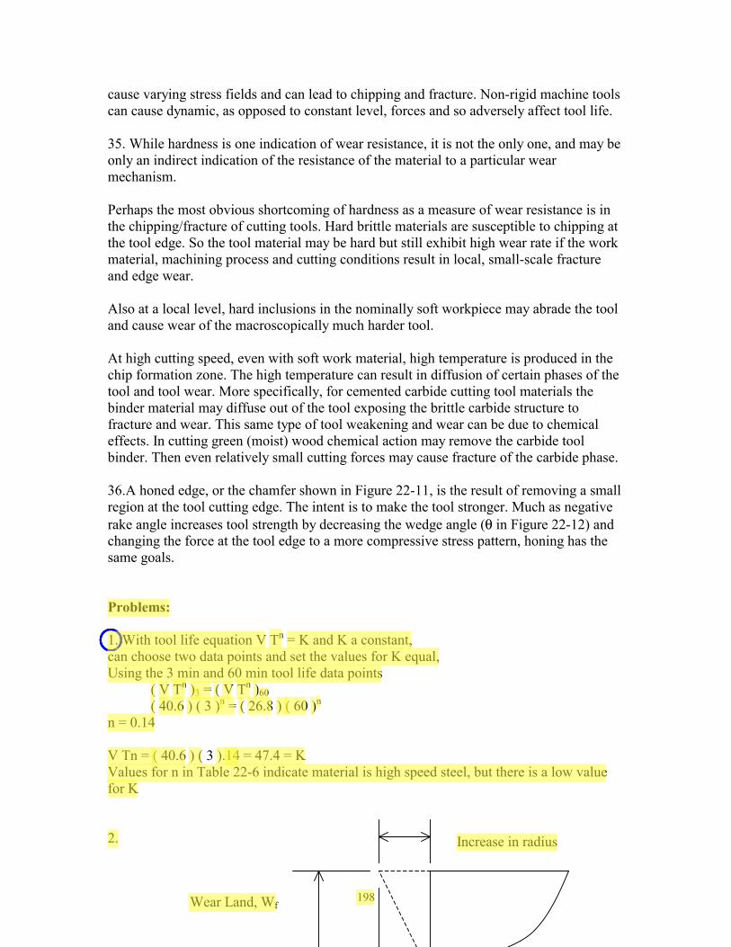
cause varying stress fields and can lead to chipping and fracture. Non-rigid machine tools can cause dynamic, as opposed to constant level, forces and so adversely affect tool life. 35. While hardness is one indication of wear resistance, it is not the only one, and may be only an indirect indication of the resistance of the material to a particular wear mechanism. Perhaps the most obvious shortcoming of hardness as a measure of wear resistance is in the chipping/fracture of cutting tools. Hard brittle materials are susceptible to chipping at the tool edge. So the tool material may be hard but still exhibit high wear rate if the work material, machining process and cutting conditions result in local, small-scale fracture and edge wear. Also at a local level, hard inclusions in the nominally soft workpiece may abrade the tool and cause wear of the macroscopically much harder tool. At high cutting speed, even with soft work material, high temperature is produced in the chip formation zone. The high temperature can result in diffusion of certain phases of the tool and tool wear. More specifically, for cemented carbide cutting tool materials the binder material may diffuse out of the tool exposing the brittle carbide structure to fracture and wear. This same type of tool weakening and wear can be due to chemical effects. In cutting green (moist) wood chemical action may remove the carbide tool binder. Then even relatively small cutting forces may cause fracture of the carbide phase. 36.A honed edge, or the chamfer shown in Figure 22-11, is the result of removing a small region at the tool cutting edge. The intent is to make the tool stronger. Much as negative rake angle increases tool strength by decreasing the wedge angle (θ in Figure 22-12) and changing the force at the tool edge to a more compressive stress pattern, honing has the same goals. Problems: 1. With tool life equation V Tn = K and K a constant, can choose two data points and set the values for K equal, Using the 3 min and 60 min tool life data points ( V Tn )3 = ( V Tn )60 ( 40.6 ) ( 3 )n = ( 26.8 ) ( 60 )n n = 0.14 V Tn = ( 40.6 ) ( 3 ).14 = 47.4 = K Values for n in Table 22-6 indicate material is high speed steel, but there is a low value for K 2.
Wear Land, Wf
Increase in radius
199
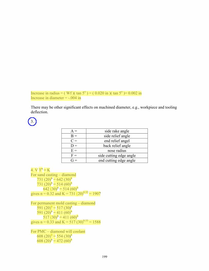
Increase in radius = ( Wf )( tan 5o ) = ( 0.020 in )( tan 5o )= 0.002 in Increase in diameter = -.004 in There may be other significant effects on machined diameter, e.g., workpiece and tooling deflection. 3.
A = side rake angle B = side relief angle C = end relief angel D = back relief angle E = nose radius F = side cutting edge angle G = end cutting edge angle
4. V Tn = K For sand casting – diamond
731 (20)n = 642 (30)n 731 (20)n = 514 (60)n
642 (30)n = 514 (60)n gives n = 0.32 and K = 731 (20)0.32 = 1907 For permanent mold casting – diamond
591 (20)n = 517 (30)n 591 (20)n = 411 (60)n
517 (30)n = 411 (60)n gives n = 0.33 and K = 517 (30)0.33 = 1588 For PMC – diamond will coolant
608 (20)n = 554 (30)n 608 (20)n = 472 (60)n
206
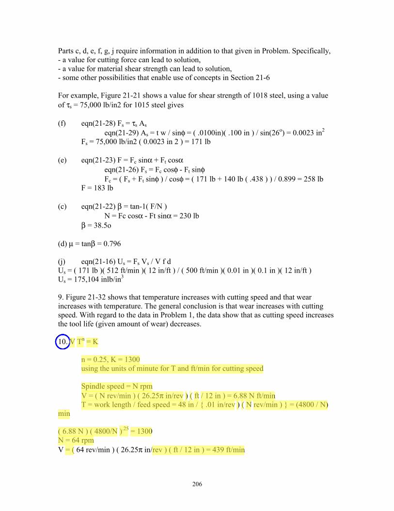
Parts c, d, e, f, g, j require information in addition to that given in Problem. Specifically, - a value for cutting force can lead to solution, - a value for material shear strength can lead to solution, - some other possibilities that enable use of concepts in Section 21-6 For example, Figure 21-21 shows a value for shear strength of 1018 steel, using a value of τs = 75,000 lb/in2 for 1015 steel gives (f) eqn(21-28) Fs = τs As eqn(21-29) As = t w / sinφ = ( .0100in)( .100 in ) / sin(26o) = 0.0023 in2 Fs = 75,000 lb/in2 ( 0.0023 in 2 ) = 171 lb (e) eqn(21-23) F = Fc sinα + Ft cosα eqn(21-26) Fs = Fc cosφ - Ft sinφ Fc = ( Fs + Ft sinφ ) / cosφ = ( 171 lb + 140 lb ( .438 ) ) / 0.899 = 258 lb F = 183 lb (c) eqn(21-22) β = tan-1( F/N ) N = Fc cosα - Ft sinα = 230 lb β = 38.5o (d) µ = tanβ = 0.796 (j) eqn(21-16) Us = Fs Vs / V f d Us = ( 171 lb )( 512 ft/min )( 12 in/ft ) / ( 500 ft/min )( 0.01 in )( 0.1 in )( 12 in/ft ) Us = 175,104 inlb/in3 9. Figure 21-32 shows that temperature increases with cutting speed and that wear increases with temperature. The general conclusion is that wear increases with cutting speed. With regard to the data in Problem 1, the data show that as cutting speed increases the tool life (given amount of wear) decreases. 10. V Tn = K n = 0.25, K = 1300 using the units of minute for T and ft/min for cutting speed Spindle speed = N rpm V = ( N rev/min ) ( 26.25π in/rev ) ( ft / 12 in ) = 6.88 N ft/min T = work length / feed speed = 48 in / { .01 in/rev ) ( N rev/min ) } = (4800 / N) min ( 6.88 N ) ( 4800/N ).25 = 1300 N = 64 rpm V = ( 64 rev/min ) ( 26.25π in/rev ) ( ft / 12 in ) = 439 ft/min

Tutorial 5:
Chapter 26: Problems 10, 11, 12 and 13 (Page 655)
Chapter 25: Problem 6, page 631.
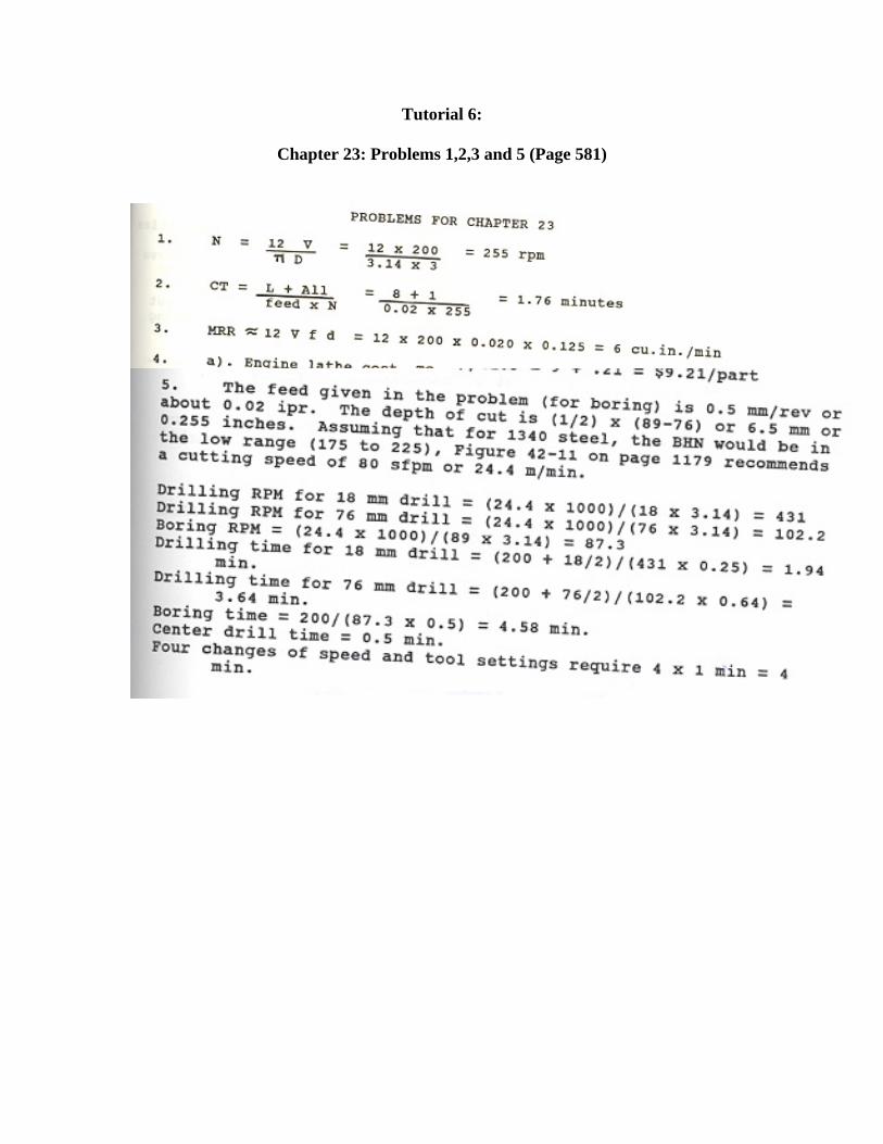
Tutorial 6:
Chapter 23: Problems 1,2,3 and 5 (Page 581)