Embed Size (px)
Citation preview

8/3/2019 Turkey Processing Plant Layout Guidelines
http://slidepdf.com/reader/full/turkey-processing-plant-layout-guidelines 1/29

8/3/2019 Turkey Processing Plant Layout Guidelines
http://slidepdf.com/reader/full/turkey-processing-plant-layout-guidelines 2/29

8/3/2019 Turkey Processing Plant Layout Guidelines
http://slidepdf.com/reader/full/turkey-processing-plant-layout-guidelines 3/29
GUIDELINES FOR TURKEY PROCESSINGPLANT LAYOUT
Marketing Research Report No. 1036
Agricultural Research Service
UNITED STATES DEPARTMENT OF AGRICULTUREIn Cooperation With
Department of Food Science and Technology
University of California, Davis

8/3/2019 Turkey Processing Plant Layout Guidelines
http://slidepdf.com/reader/full/turkey-processing-plant-layout-guidelines 4/29
8/3/2019 Turkey Processing Plant Layout Guidelines
http://slidepdf.com/reader/full/turkey-processing-plant-layout-guidelines 5/29
ACKNOWLEDGMENTS
The study, conducted and reported herein, was made possible through
cooperative effort of the University of California, Davis, Departmentsof Food
Science and Technology and Agricultural Engineering, and the AgriculturalResearch Service, U.S. Department of Agriculture.
Appreciation is expressed to inspection personnel of Animal and Plant
Health Inspection Service for their cooperation.The wholehearted cooperation of commercial plant personnel and manage-
ment, who helped to make this researchpossible,
has added greatly to the
meaningfulness of this report. Without their support, this research would not
have been possible.
The authors acknowledge the contributions of Thomas W. Tesche, and
George W. Mock, civil engineering students, University of California, Davis,
who prepared field notes on refrigeration and floor material tests.

8/3/2019 Turkey Processing Plant Layout Guidelines
http://slidepdf.com/reader/full/turkey-processing-plant-layout-guidelines 6/29
CONTENTSPage
Summary 1
Background 1
Systematic layout planning2
The facility layout3
Live bird receiving area 3
Slaughtering area 5
Scalding and defeathering 5
Scalding area 5
Defeathering area 1
Offal room 8
Eviscerating and chilling 8
Eviscerating area 8
Chilling area 10
Packaging 10
Shipping11
Offices and personnel facilities 12
Expansion of basic plant 12
Blast freezing area 12
Cold storage area 14
Further processing area ^ 14
Refrigeration system 18
Storage of packaging materials 18
Plant structure 19
Site location and plan 20
Additional regulatory requirements and considerations 22
Literature cited 22
May 1975
8/3/2019 Turkey Processing Plant Layout Guidelines
http://slidepdf.com/reader/full/turkey-processing-plant-layout-guidelines 7/29
GUIDELINES FOR TURKEY PROCESSINGPLANT LAYOUT
By W. L. SHUPE, research mechanical engineer, and E.W. SPANGLER, engineering technician (retired), AgriculturalResearch Service (ARS) t
Western Region, University ofCalifornia, Davis; JOHN A. HAMANN, Chief(retired),Dairy and
Poultry Products MarketingLaboratory, Agricultural MarketingResearchInstitute, ARS,Beltsville,Md.;BRANT, food technologist, University of California, Davis
SUMMARY
An efficient layout of a basic plant for proc-
essing whole, ready-to-cook turkeys and provisionfor further processing is developed and described
in this report. The intent is to assist plantoperators with layout and design features for
completely new plants as well as additions to, andrenovation of, existing facilities when productionrates are increased and new products are proc-essed.
Step-by-step_additions to the basic plant
(slaughter and evisceration operations) include
fast freezing, frozen storage, and further process-
ing of the whole carcass into convenience items.
This layout provides for efficient productflow
throughout the entire operation without inter-
fering with production or necessitating major
changes in any completed section of the plant if
and when the additions are made.
Planned production rates for this plant layout
vary from 160,000 pounds of turkey products per
day, using a single eviscerating line, up to
300,000 Ib/day when a double line is used, For
good manageability, a plant layout design should
provide for expansion and product diversification.
The major guidelines taken into account in pre-
paring the plant layout include the following:
(1) Where a specific operation is performed, each
area is arranged to permit efficient operation and
a direct flow of the product; (2) in the overall
plant layout, each area is connected in sequenceto allow smooth flow of products and materials
through the entire plant; and (3) provisions for
meeting regulatory requirements include (a)
product wholesomeness, (b) personnel health andsafety, (c) employee comfort and convenience, and
(d) plant maintenance.
BACKGROUND
Turkeys are a seasonal crop. A large percentageof the annual crop is slaughtered from early fall
through the holiday season. In the past, these
birds were marketed as whole turkeys onlyfirst as New York-dressed, later as ready-to-cook
(eviscerated) birds. If these were not all sold dur-
ing the holiday season, the balance was held in
commercial cold storage plants until they weremarketed as whole birds. In the early days, proc-
essing plants were designed for processing NewYork-dressed turkeys and generally shut downwhen the marketing season was over. The season
generally lasted from September to January.
Freezing and low temperature storage facilities
were provided by commercial cold storage houses.
With the advent of plants converting to ready-to-cook operations and U. S. Department of Ag-riculture (USDA) inspection for wholesomeness,it became possible to further process turkeys into
specialty items at times when the plants would
normally have been shut down. By further proc-
essing whole, ready-to-cook turkeys into conven-ience items such as turkey parts, boned turkeymeat, rolled roasts, frozen dinners, and pot pies
many turkey processing plants have becomeyear-round operations. These modern methods of
marketing turkeys have changed the plant from
the early day slaughterhouse into a modern foodprocessing facility. In accomplishing this complexstep, turkey processors greatly increased their
investment in facilities and equipment. In manycases, alterations and additions were made to ex-
isting structures. This usually required a plantshutdown during alteration, which, under today's
operating conditions, is inconvenient and costly.
Unfortunately, the layouts that resulted, in manycases, were inefficient.
Much progress has been made by processors,
researchers, and equipment manufacturers in
improving methods and equipment used in the
1
8/3/2019 Turkey Processing Plant Layout Guidelines
http://slidepdf.com/reader/full/turkey-processing-plant-layout-guidelines 8/29
MARKETING RESEARCH REPORT 1036, U.S. DEPARTMENT OF AGRICULTURE
industry. Compliance as to product wholesome-
ness and facility acceptability is now requiredunder the terms of the Poultry Products Inspec-
tion Act of 1957 (II),1
the Williams-Steiger Oc-cupational Safety and Health Act of 1970 (9), andthe Federal Water Pollution Control Act as
amended in 1972 (8). When planning new struc-
tures or remodeling existing facilities, plantmanagement has to meet the requirements set bythese laws while developing an efficient layoutfor processing operations. The intent of this re-
port is to assist plant operators with layout and
design features for completely new plants as well
as additions to, and renovation of, existingfacilities when production rates are increased and
new products are processed.
This information is based on studies made at a
number of turkey processing plants in the West-
ern United States and supplemented with re-
search data from earlier work reported in publi-
cationsby
the Agricultural Research Service, Ag-ricultural Marketing Service, and Animal andPlant Health Inspection Service (2, 7, 10, 12, 13).
SYSTEMATIC LAYOUT PLANNING
The basic factors to consider when planning anefficient industrial food processing plant layout
(4, 5, 6) are: (1) Nature of the raw materials andfinished products; (2) production rate for each
product; (3) number of work stations and area re-
quired for each operation; (4) location of specificwork areas in relation to one another; and (5)
structural design required for economic future
expansion with minimal disruption of operations.In addition to these considerations, location of
facilities auxiliary to the production operation,such as management offices and personnelamenities, should be conveniently located. Theseareas would include office space, restroom andtoilet facilities, and a lunchroom, which can be
planned for convenience without interfering with
plant operations.
To convert live turkeys into whole, ready-to-cook carcasses, the live birds are hung on a
shackle and moved through the entire process onoverhead monorail conveyors in an assembly line
type of operation. The first step in the operation is
to place the live bird on the conveyor at the
receiving dock. The steps that follow in sequenceare slaughter, scald, defeather, and wash. The de-
feathered and washed carcass is then transferredto the overhead eviscerating conveyor that car-
ries the bird through the eviscerating area in the
process of converting "it into the whole body,
ready-to-cook form. It is then chilled. This is fre-
quently done in an inline-type chiller that sub-
merges the bird in water and crushed ice as it is
moved forward and emerges ready for draining,
wrapping, or further processing.In establishing the most desirable production
rate for the plant, the most complex processingoperation value is used for a base. In a turkeyprocessing plant, more than 50 percent of the
lineworkers are involved with the evisceratingoperation. The optimum rate at which this opera-tion can be accomplished, as well as the rate atwhich the USDA inspector can adequately in-
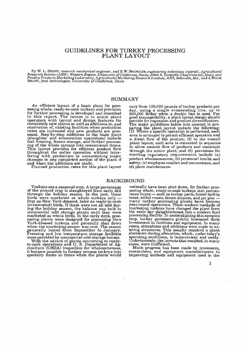
spect (11), controls the production rate. Apro-
duction rate of 300,000 pounds of dressed turkey
per day was selected for this report, based on re-
cent research (7) with optimum worker utiliza-
tion. Figure 1 shows the relationship of one activ-
ity area to another and of the space requirementsfor each in a turkey processing plant of this pro-duction rate. The diagram also shows product and
packaging materials flow lines, which are very
important and must be given considerable atten-
tion when planning the overall layout for an effi-
cient operation. Auxiliary or service areas are
also shown in this diagram and must be con-
sidered in the final plant layout.The use of scaled templates and a layout board
are useful tools in planning a layout. This methodoffers the designers a chance to
try many changesin arriving at the most efficient layouts without
making time-consuming changes in drawings.
Turkey processors who start with the preparationof whole, ready-to-cook, chilled birds and changeover to more complex operations by adding freez-
ing, cold storage, and further processing facilities
will benefit by this approach.
1Italic numbers in parentheses refer to Literature
Cited, p. 22. FIGURE I. Space relationship flow diagram.

8/3/2019 Turkey Processing Plant Layout Guidelines
http://slidepdf.com/reader/full/turkey-processing-plant-layout-guidelines 9/29
TURKEY PROCESSING PLANT LAYOUT
THE FACILITY LAYOUT
The basic plant layout shown in figure 2 illus-
trates the location and space requirements of thevarious areas for a plant processing 300,000
pounds. of whole, ready-to-cook turkey daily with
provisions for step-by-step additions to handle
rapid freezing, frozen and cold storage, andfurther processing. The first addition is the blast
freezer.2
Its capacity is 300,000 pounds, or one
day's production. The next addition is the cold
(35 F) and frozen (0) storage areas. A capacity of
3 million pounds, which is 10 days' production,was chosen arbitrarily. Marketing conditions
cause the storage capacity to vary greatly from
place to place.
The further processing area is the third addi-
tion planned. Further processed turkey productsare quite numerous and require a large assort-
ment of packaging materials, necessitating addi-
tional dry materials storage space. This storage
space is provided on the second floor over the
blast freezer addition (fig. 3).
A receiving dock for plant supplies and packag-ing materials is included in the third addition.
This eliminates crowding and confusion in the
product shipping area when further processedproducts are produced.The basic layout was developed with the fun-
damentals of systematic planning in mind. It con-
sists of major activity areas for live bird receiv-
ing, slaughtering and defeathering, eviscerating,
chilling, packaging, and shipping whole, ready-
to-cook birds. The auxiliary or service areas
such as live bird truck washing, boiler room,utilities room, offal handling, ice manufacturingand storage, offices, personnel facilities, and
packaging materials storage and makeup (fig.
1) have been placed in locations that permit asmooth product flow
through the facility. Thethree additions, blast freezing, frozen storage,and further processing (fig. 2), can be broughtabout without costly renovations to existing areasof operation or disruption of production. Thus,with minimal congestion, bottlenecks, and cross
traffic, live bird trucks unload at one aide of the
plant, supplies and packaging materials are re-
ceived on the other, offal trucks are loaded at the
rear, and the product is loaded at the front next to
the office.
For a smaller operation with a daily productionrate of 150,000 pounds, the basic plant for proc-
essing whole, ready-to-cook chilled birds can be
operated with a single eviscerating line and cor-
respondingly less slaughtering, scalding, and de-
feathering capacity. Structural dimensions of the
basic plant should not be reduced for this lower
production rate because relocating major equip-ment in these areas when production is increased
would be very costly and time consuming. Thethree additions can vary in dimensions best
suited to the needs established by area and
marketing requirements.
LIVE BIRD RECEIVING AREA
In the case-study plants observed in this re-
search, birds were transported to the processing
plant in vans inbattery-type cages permanently
attached to the vehicle, when the van first ar-
rives at the plant, it is weighed and then moves to
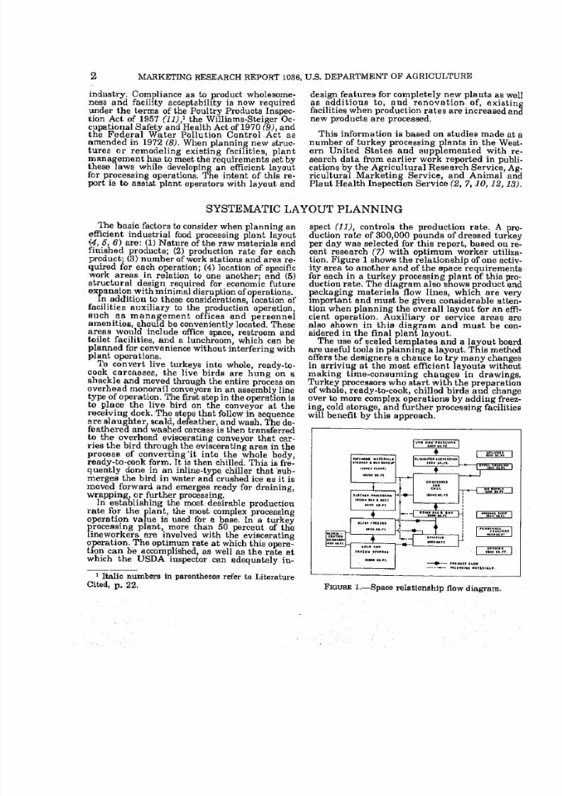
the unloading area (fig. 4), where adjustable
height conveyors and worker platforms provide
easy reach for workers while hanging birds in
shackles(fig.
5). An electric hoist and cable sys-
tem can position either side independently, allow-
ing for variations in work rates. Another methodof doing this can be accomplished by means of a
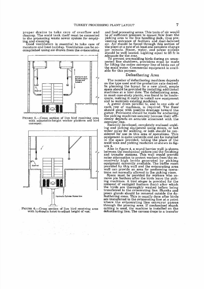
hydraulic hoist (fig. 6). The hoist raises the van to
initially, access is through a temporary doorway(not shown) in the shipping dock wall. After the secondaddition is completed, the door opening is moved to thecold storage room wall, and access to the freezer is
through a door from the freezer to the cooler, establish-
ing a vestibule effect for the freezer.
the desired height to permit workers on raised
platforms a convenient reach into each compart-ment level. The dock is wide enough to provide for
a walkway and permits unloading from both sides
of the truck. In addition, the dock is long enoughto accommodate double trailers in areas wheredoubles are used.
A van-washing area is provided for cleaningafter
unloading.The whole dock area should
becovered to provide shelter for workers, birds, and
equipment during inclement weather. Suction
fans are suggested for use over the center of the
dock area for ventilation and picking up the loose
feathers.
In the area between unloading birds from the
truck anddispatching birds, a clear area for
USDA ante mortem inspection and necessaryfacilities must be provided. A small office andrestroom for truckdrivers, receiving clerk, andother workers in this area of the plant, have been
provided in the office and personnel facilities sec-
tion of the plant (see p, 13),

8/3/2019 Turkey Processing Plant Layout Guidelines
http://slidepdf.com/reader/full/turkey-processing-plant-layout-guidelines 10/29
MARKETING RESEARCH REPORT 1036, U.S. DEPARTMENT OF AGRICULTURE

8/3/2019 Turkey Processing Plant Layout Guidelines
http://slidepdf.com/reader/full/turkey-processing-plant-layout-guidelines 11/29
TURKEY PROCESSING PLANT LAYOUT
SECTION A-A
BOX MAKEUP
C==}FLOOR WELLFOR
BOX CHUTE
BOX MAKE UPAND
STORAGE
1FLOOR WELLJ FORBOX CHUTE
BASIC PLANT
'Sliding door
ADDITION NO, I
DRY MATERIALS STORAGEOVERBLAST FREEZER
SCALE OF FEET
10 20 30 10 SO
FIGURE 3. Second floor layout and section view of part of basic plant and additions.
SLAUGHTERING AREABirds enter the blood tunnel (fig. 4) on the
overhead conveyor, hanging by their feet. It is
important to allow enough width (6 feet) in this
tunnel to prevent bruising by birds flapping
against walls. The blood tunnel should be of suffi-
cient length to allow ample bleeding time before
scalding. The actual length depends on line speedand the estimated time required for adequate
bleeding. USDA regulations require that blood
from the slaughter operation be confined effec-
tively. Since most local regulations prohibit
dumping blood into sewerlines, it is generally
disposed of after coagulation. Two methods of
doingthis
are used: (1) Coagulated blood is sweptinto a collection gutter and moved to the ofml
room by auger, or (2) a vacuum system, similar to
that used for lung removal, is used periodically to
suck coagulated blood from the gutter to the offal
room.
The ceiling, floor, and walls of the slaughterarea and blood tunnel must be washed down regu-
larly, necessitating the use of a glazed surface
that is impervious to moisture. Hot and cold
water outlets and steam must be provided at con-
venient locations for cleanup of the area. A spaceheater should be provided for the area to provideworker comfort in cold weather. Lighting equal to
30 footcandles (fc) at the slaughtering station and10 fc in the blood tunnel is suggested as sufficient.
Fans should be provided for adequate ventilationfor personnel in the tunnel and at the slaughter-
ing station.
SCALDING AND DEFEATHERING
Scalding Area
As' the birds leave the blood tunnel, they enter
the scald tank. The dimensions of this tank are
controlled by the line speed and time required for
loosening the feathers. The conveyor line can be
constructed so as to make one or more passes
through the tank, One pass requires a long, nar-
row tank, whereas two passes would reduce the
length, but add to the width. The dimensions ofthe space available for this purpose would be the
deciding factor as to the number of passes birds
make through the tank. Tanks are manufa,cturedin sections
allowingfor this dimensional varia-
tion. The floor in this area must be provided with

8/3/2019 Turkey Processing Plant Layout Guidelines
http://slidepdf.com/reader/full/turkey-processing-plant-layout-guidelines 12/29
MARKETING RESEARCH REPORT 1036, U.S. DEPARTMENT OF AGRICULTURE
8/3/2019 Turkey Processing Plant Layout Guidelines
http://slidepdf.com/reader/full/turkey-processing-plant-layout-guidelines 13/29
TURKEY PROCESSING PLANT LAYOUT
proper drains to take care of overflow and
cleanup. The scald tank itself must be connected
to the processing waste sewer system for empty-
ing and cleaning.
Good ventilation is essential to take care of
moisture and heat buildup. Ventilation can be ac-
complished using air drawn from the eviscerating
FIGURE 6. Cross section of live bird receiving area
with adjustable-height worker platform and bird
conveyor.
JA.FIGURE 6, Cross section of live bird receiving area
with hydraulic hoist to adjust height of van.
and food processing areas. This train of air would
be of sufficient pressure to ensure flow from the
picking area to the live handling dock, thus pre-
venting entrance of feathers and dust-ladened
air. Air should be forced through this section of
the plant at a rate of at least one complete change
per minute. Steam, water, and power outlets
should be well located. Lighting equal to 25 fc is
adequate for the area.
To prevent overscalding birds during an unex-
pected line shutdown, provisions must be madefor lifting the entire conveyor line of birds out of
the scald water. Commercial equipment is avail-
able for this purpose,
Defeathering Area
The number of defeathering machines dependson the type used and the production rate desired.
Inplanning
thelayout
for a newplant, amplespace should be provided for installing additional
machines at a later date. The defeathering area,in most case-study plants, was found to be inade-
quate, making it costly to install new equipmentand to maintain existing machines.
A gutter drain parallel to, and to one side of
each row of machines, is required. The floor
should slope with positive drainage toward the
gutter. Provisions should be made for anchoringthe picking machines securely because their effi-
ciency depends on accurate alinement with the
conveyor line.
Recently developed, completely enclosed scald-
ing and picking equipment using steam, or hot
waterspray
forscalding,
or both should be con-
sidered for use in this area of operations, This
equipment is quite versatile and can be installed
in the space provided, taking the place of the
scald tank and picking machines as shown in fig-
ure 4.
Also in figure 4, a sound barrier wall is shownbetween the mechanicalpickers and the finishingand transfer stations. This wall would providenoise attenuation to protect workers from the ex-
cessively high levels generated by picking
equipment currently available. The buffer room
provided by this wall and the eviscerating area
wall can provide an area for performing opera-tions not normally allowed in the picking room.
Spacemust be
providedfor workers who re-
move pin feathers after the birds leave the pick-
ing machines. A bird singer is provided for the
removal of vestigial feathers (hair) after whichthe birds are thoroughly washed before beingtransferred to the eviscerating line. Shanks and
preen glands should be removed outside the de-
feathering room. This is usually done after birds
are transferred to the eviscerating line at a pointwhere the eviscerating line conveyor passesthrough the pinning area. If mechanized shank
cutting is used, the machine is installed on the
defeathering line. The carcass drops to a transfer

8/3/2019 Turkey Processing Plant Layout Guidelines
http://slidepdf.com/reader/full/turkey-processing-plant-layout-guidelines 14/29
8 MARKETING RESEARCH REPORT 1036, U.S. DEPARTMENT OF AGRICULTURE
belt as the shanks are cut. The shanks continue
on and are mechanically released from the
shackle at any desirable locations as the shackle
returns to the live bird hanging area. The pinning
operation requires close inspection necessitating
good lighting. A minimum of 50 fc of light is re-
quired for this area. As in other areas, hot water
and steam outlets must be provided for cleanupoperations.
OFFAL ROOM
Approximately 20 percent of the live weight of
turkeysprocessed is discarded as inedible material
in the form of blood, feathers, viscera, feet, heads,
condemned carcasses, and parts. A plant proc-
essing 37,000 pounds of eviscerated turkeys per
hour accumulates about 7,500 pounds of offal
each hour. Facilities must be provided for rapid
removal of this waste to prevent creating a nui-
sance andcontaminating
edibleproducts.The offal room should be located adjacent to the
defeathering and the eviscerating areas. This al-
lows a minimum distance for moving feathers and
offal to the offal room. All gutters must be large
enough to handle the necessary volume of water3
and waste and sloped for effective movement of
waste product. Feather gutters require less slope
than offal gutters from the eviscerating area;
1-inch slope per 50 feet for feathers and 1-inch
slope per 19 feet for viscera are recommended.
Blood from the blood tunnel is usually combined
with the feathers for disposal. Feather disposal
gutters and viscera disposal gutters empty into
different mechanical separators in the offal room,where the solids are separated from the water.
Feathers and other offal are then conveyed to
separate, waiting trucks. As a water-conserving
measure, some of the water from the separatorscan be recirculated to assist in feather flowaway.The
truck-loading
area should be sloped to trap-
ped drains for carrying off seepage and washdownwater.
Two pits with floors dropped 3 to 4 feet, one for
feathers and one for other offal, are provided in
the offal room. This allows for sloping floor gutterdrains and for installing separators and pumps.The floors should be sloped toward the pits, and
the walls should be of moisture-impervious mat-
erial, as frequent washdown is required for sani-
tation.
EVISCERATING AND CHILLING
In plants preparing only whole, ready-to-cook
turkeys, 50 percent or more of the plant workers
work in the eviscerating area. Therefore, particu-
lar attention should be given to the design and
layout of work stations, aisle space, noise level,
ventilation, andproper placement of personnel
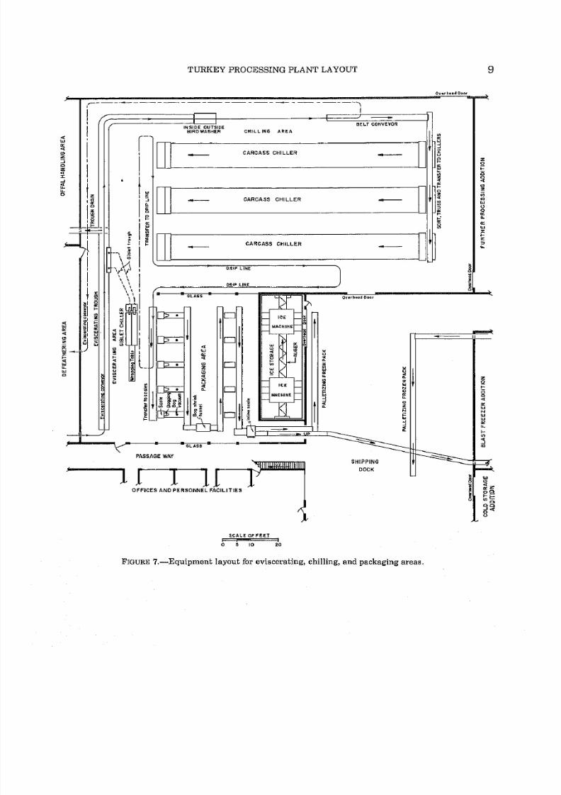
facilities. Figure 7 shows an efficient layout for
this area.
The eviscerated carcasses are chilled promptlyafter evisceration, Plants with further processing
operations do not truss4 birds that are to be cut
up. This requires that birds to be cut up be sepa-
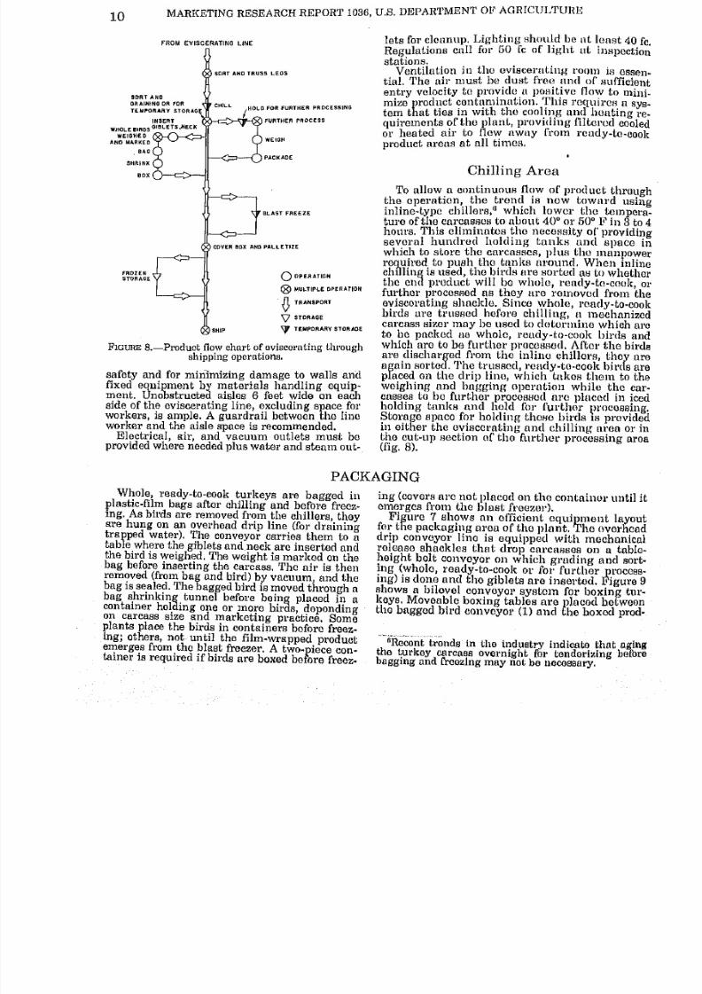
rated from the trussed birds before chilling. Fig-
ure 8 is a product flow chart, which identifies op-
erations fromeviscerating through shipping
and
shows the alternate routes the product may take
before reaching the shipping dock,
Eviscerating Area
The main equipment item in this area, is the
bird single or dual conveyor line, over a water-
Research is now underway to reduce water-use rates
by providing vacuum pickup of all offal and feathers.
flushed offal trough. (Dry removal of offal5 maytake the place of the water-flushed trough with-
out changing the layout, as shown in fig. 7.)
Hand-wash nozzels are required at each
3-foot-long work station along the line. Foot or
hip pedal-operated, self-closing-type valves are
recommended on hand-wash nozzles as a means of
conserving water.
The overhead monorail conveyor height should
be located so that the birds reach the tallest
workers at approximately their elbow height. Ad-
justable platforms can be used to elevate shorter
workers to the same height. Conveyor line wear
can be decreased and maintenance costs reduced
if horizontal and vertical curves are held to a
minimum.The line should be long enough to provide
3-foot-long work stations for each worker and 8
feet for inspection (including room for trimmers),
plus additional space for training new workers.
The offal trough should be wide enough to
accommodate the dual line even though a single
line is first contemplated. In case of expansion,
relocating or installing new equipment is expen-sive and necessitates a long period of shutdown.
Adequate aisle space is essential for personnel
4Whole, ready-to-cook birds are generally trussed.
6See footnote 3.
8/3/2019 Turkey Processing Plant Layout Guidelines
http://slidepdf.com/reader/full/turkey-processing-plant-layout-guidelines 15/29
TURKEY PROCESSING PLANT LAYOUT 9
OvihnJ Door
INSIDE OUTSIDEBIRD WASHER
BELT CONVEYOR
CHILLING AREA
I 5
CARCASS CHILLER
CARCASS CHILLER
CARCASS CHILLER
OHlP LINE
i
\
PASSAGE WAY
OFFICES AND PERSONNEL FACILITIES
SHIPPING
DOCK
SCALEOFFEET
B 10
FIGURE 7, Equipment layout for eviscerating, chilling, and packaging areas.
8/3/2019 Turkey Processing Plant Layout Guidelines
http://slidepdf.com/reader/full/turkey-processing-plant-layout-guidelines 16/29
10 MARKETING RESEARCH REPORT 1036, U.S. DEPARTMENT OF AGRICULTURE
FROM EVISCERATING LINE
SORT AND TRUSS LEGS
SORT ANDDRAINING OR FOR
TEMPORARY STORAO
INSERT
WHOLEB.RDSGI8LETS 'HECK
WEIGHED
AND MARKED
.BAG
SHRINK
HOLD FOR FURTHER PROCESSING
FURTHER PROCESS
^r BLAST FREEZE
COVER BOX AND PALLETIZE
r^ROZEN t-L,
STORAGE V{
UJ
i OPERATION
MULTIPLE OPERATION
TRANSPORT
STORAGE
TEMPORARY STORAGE
FIGURE 8. Product flow chart of sviacernting through
shipping operations.
safety and for minimizing damage to walls and
fixed equipment by materials handling equip-ment. Unobstructed aisles 6 feet wide on each
side of the eviscerating line, excluding space for
workers, is ample. A guardrail between the line
worker and the aisle space is recommended.
Electrical, air, and vacuum outlets must be
provided where needed plus water and steam out-
lets for cleanup. Lighting should bo at least 40 fc.
Regulations call for 60 fc of light ut inspection
stations.
Ventilation in the eviscerating room is essen-
tial. The air must be dust free and of sufficient
entry velocity to provide a positive (low to mini-
mizeproduct
contamination. This requires a sys-
tem that ties in with the cooling and heating re-
quirements of the plant, providing filtered cooled
or heated air to flow away from ready-to-cook
productareas at all times.
t
Chilling Area
To allow a continuous flow of product throughthe operation, the trend is now toward usinginline-type chillers," which lower the tempera-ture of the carcasses to about 40 or 60 F in 3 to 4
hours. This eliminates the necessity of providingseveral hundred holding tanks and space in
which to store the carcasses, plus the manpowerrequired to push the tanks around. When inline
chilling is used, the birds are sorted as to whetherthe end product will bo whole, ready-to-cook, or
further processed as they are removed from the
eviscerating shackle. Since whole, ready-to-cookbirds are trussed before chilling, a mechanizedcarcass sizer may be used to determine which are
to be packed as whole, reudy-to-cook birds andwhich are to be further processed. After the birds
are discharged from the inline chillers, they are
again sorted. The trussed, ready-to-cook birds are
placed on the drip lino, which takes them to the
weighing and bagging operation while the car-
casses to bo further processed are placed in iced
holding tanks and held for further processing.Storage space for holding these birds is providedin either the eviscerating and chilling area or in
the cut-up section of the further processing area
(fig. 8).
PACKAGING
Whole, ready-to-cook turkeys are bagged in
plastic-film bags after chilling and before freez-
ing. As birds are removed from the chillers, theyare hung on an overhead drip line (for drainingtrapped water). The conveyor carries them to atable where the giblets and neck are inserted andthe bird is weighed, The weight is marked on the
bag before inserting the carcass. The air is thenremoved (from bag and bird) by vacuum, and the
bag is sealed. The bagged bird is moved through a
bag shrinking tunnel before being placed in a
container holding one or more birds, dependingon carcass size and marketing practice. Someplants place the birds in containers before freez-
ing; others, not until the film-wrapped productemerges from the blast freezer. A two-piece con-tainer is required if birds are boxed before freez-
ing (covers arc not placed on the container until it
emerges from the blast freezer).
Figure 7 shows an efficient equipment layoutfor the packaging area of tho plant. The overhead
drip conveyor lino is equipped with mechanicalrelease shackles that drop carcasses on a table-
height belt conveyor on which grading and sort-
ing (whole, roady-to-cook or for further process-ing) is done and the giblets are inserted. Figure 9shows a bilevol conveyor system for boxing tur-
keys. Moveable boxing tables areplaced
betweentho bagged bird conveyor (1) and the boxed prod-
"Recont trends' in tho industry Indicate that agingthe turkey carcass overnight for tenderizing before
bagging ana freezing may not be necessary.

8/3/2019 Turkey Processing Plant Layout Guidelines
http://slidepdf.com/reader/full/turkey-processing-plant-layout-guidelines 17/29
8/3/2019 Turkey Processing Plant Layout Guidelines
http://slidepdf.com/reader/full/turkey-processing-plant-layout-guidelines 18/29
12 MARKETING RESEARCH REPORT 1036, U.S. DEPARTMENT OF AGRICULTURE
handling; (3) icing the boxes, if necessary; (4) clos-
ing boxes; (5) occasionally labeling; and (6) re-
cording weights.
The shipping dock, as planned, accommodates
five trucks. Space has been provided for making
up mixed orders of various products (whole,
ready-to-cook birds, chilled or frozen, and further
processed items) for the same shipment.
Truck-bed heights vary from 46 to 56 inches
when loaded and may be 6 to 8 inches higher
when empty. A 48-inch dock height has proved
satisfactory. Vertical clearance from ground to
roof should be a minimum of 14 feet. A roof over-
hang of at least 4 feet should be provided for
weather protection of the loading operation.
Overhead doors may be installed at the dock
openings if it is desirable to enclose the area.
The general office adjoins the order makeuparea of the shipping department and is provided
with windows, permitting management to ob-
serve operations.
OFFICES AND PERSONNEL FACILITIES
Pleasant comfortable surroundings contribute
greatly toward worker productivity and improve
quality ofworkmanship. In plants where pleasant
surroundings have been provided, employeemorale was observed to be much higher, resulting
in a reduction of labor turnover. Providing a
clean, well-lighted lunchroom; washrooms with
adequate easily cleaned toilet facilities; well-
equipped first-aid rooms; and an adequate park-
ing area, conveniently located, reflect
management's concern for employee welfare that
is proving effective in reducing absenteeism.
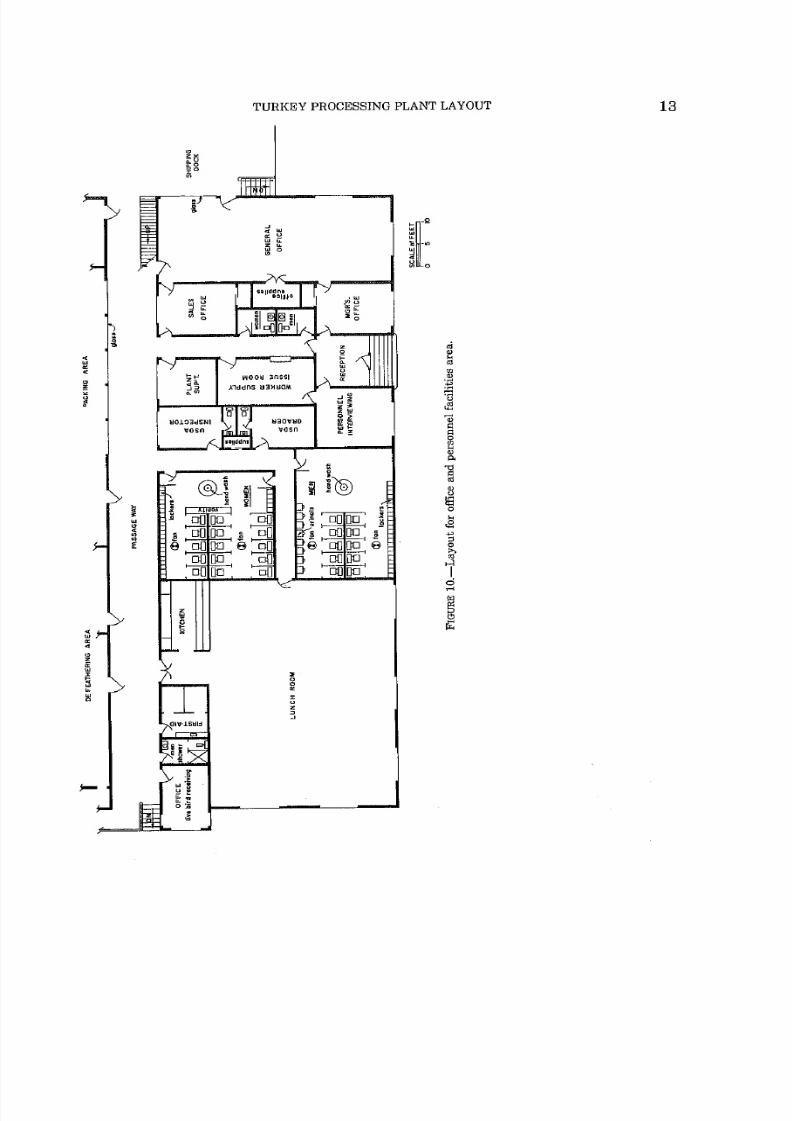
In developing the basic plant layout (fig. 2),
consideration was given to locating the employee
facility and office area portion of the plant con-
venient to the work areas, yet keeping all areas
for facilities auxiliary to processing operations
grouped together in the same wing of the overall
plant. This allows for surrounding the area withfour masonry-type load bearing walls and cover-
ing it with a clear span of roof structure. All in-
terior partitions may be of wood frame and dry
wall paneling. Ceilings are lightweight,
suspended-type panels. This allows for versatility
in the layout of this area, which would greatly
reduce costs of remodeling and renovation in the
future. Figure 10 is a suggested layout of em-
ployee facilities and offices in this area. Space is
shown for USDA inspector and grader offices. Air
conditioning, both heating and cooling, for
worker comfort is essential. Self-contained units
suspended from the ceiling may be used.
Washrooms include lockers for employees' per-
sonal belongings, handwashing facilities, and
toilet facilities. Regulations call for a minimum
number of toilets and other requirements tor
poultry processing plants. Separate personal
facilities have been provided for officeworkers. A
washroom with shower and toilet is provided near
the live bird receiving and slaughter areas for
workers in these areas.
Adequate ventilation must be provided in all
washrooms. This can be accomplished with buu*>
in ceiling fans or screened window openings it the
windows are located on exterior walls. Tinted
concrete floors and ceramic tile wainscoting for
walls are highlyrecommended for sanitation and
pleasing appearance. All fixtures should be of the
wall-hung type. Circular, foot-pedal controlled
wash fountains require less space and are easy to
keep clean. A few vanity-type lavatories with
wall mirrors are suggested for the women s rest
area. Good lighting, about 40 fc, is suggested. If
electrical outlets are provided, they should be
kept a safe distance from any water outlet and at
least 12 inches above floor level. Both hot and
cold water must be provided at washstands.
EXPANSION OF BASIC PLANT
In addingto the basic
plant,
as previously de-
scribed, blast freezing, cold storage, and further
processing areas can be added with minimum dis-
ruption to plant operations.
Blast Freezing Area
The first addition to the basic plant consists of
the blast freezing compartment, refrigeration
machinery room, the passageway alongside the
blast freezer, and additional dry materials stor-
age area on a second floor level above the freezer
(figs. 2 and 3). The passageway area serves as a
receiving dock for packaging materials and other
plant supplies before adding the further process-
ing additions.
Turkey products; whole, ready-to-cook birds;
and further processed items must be hard frozen
as rapidly as possible after chilling or processing
to maintain quality and minimize spoilage
hazards. This is best accomplished by directing a
-30 to -50 F blast of air, with a velocity of 400
to 500 ft/min, over the product. To allow the cold
air to circulate freely, the product is stacked on
racks with space between containers. In the past,
these racks were transported into the freezer and,
after the freezing compartment was filled, the
8/3/2019 Turkey Processing Plant Layout Guidelines
http://slidepdf.com/reader/full/turkey-processing-plant-layout-guidelines 19/29
TURKEY PROCESSING PLANT LAYOUT 13

8/3/2019 Turkey Processing Plant Layout Guidelines
http://slidepdf.com/reader/full/turkey-processing-plant-layout-guidelines 20/29
14 MARKETING RESEARCH REPORT 1036, U.S. DEPARTMENT OF AGRICULTURE
door was closed, and the refrigeration and fans
were turned on. When freezing was completed,the system was turned off, the door was opened,and the entire batch of product was removed. In
recent years, equipment manufacturers have de-
veloped mechanized conveyor systems that allow
a continuous inline-type product flow through the
fast freezing operation. One method used is illus-
trated in figure 11.
The product enters the freezer on a conveyorbelt. When it reaches a position in line with the
rack, it is mechanically pushed onto the rack
shelf. When the shelf is full, the rack rises to the
next shelf for loading. The loaded racks are then
moved slowly across the top section of the freezer,
lowered to the bottom section, then returned to
the starting point where the frozen product is
mechanically pushed onto the conveyor belt,
which carries it to the sorting and palletizingarea.
For an efficient operation, the blast freezer
must be of sufficient capacity to freeze the productat the same daily production rate as the eviscerat-
ing and chilling operations. This prevents a
bottleneck at this point in theproduction line, at
times when the entire production is to be frozen.
The blast freezer, as planned in this report,should be large enough to hold an entire day's
production with enough allowance for days of
high production, that is, if extra birds are proc-essed. The refrigerating equipment must be of
sufficient tonnage tocompletely freeze these birds
in a 24-hour period. This means that the workcrew that handles the frozen product should start
their daily shift 6 hours later than the work crewin the processing area. Figure 12 is a schematicsketch showing the 6-hour difference in startingtimes for the work crews.
Cold Storage Area
The cold storage addition consists of tworooms the frozen storage area held at F for
long-term storage of frozen product and thesmaller cold storage area held at 35 for short-term storage of chilled product. The 35 area also
serves as an anteroom for entering the frozen
storage area. This conserves on refrigeration forthe frozen storage room and minimizes moisture
buildup around door openings.
One of the most important structural featuresto consider when planning cold storage facilities
is the use of moisture-impervious materials for
walls, ceilings, and floors. If moisture penetratesthese surfaces, the insulating efficiency de-creases. Formation of ice crystals may cause
heaving of floor slabs and general breakdown ofother building materials. Doors for movement of
product in and out are another problem area. If
hinged wooden doors are used, they should becovered with metal and sealed to prevent mois-ture absorption and to protect the wood from
damage by handling equipment. The ideal
method of solving this problem in areas of heavyin and out traffic is the use of an air curtain.
Under these conditions, however, air curtain fans
tend to ice up if they are mounted inside the cold
room; therefore, outside mounting is called for.
The cold storage area, as planned in this report,has a ceiling height of 25 feet, allowing palletloads of product to be stacked four high (neces-
sitating the use of pallet racks) and leaving aminimum of 3 feet clearance about the stack for
air circulation. The use of pallet racks in storageareas eliminates carton damage caused by exces-sive weight at the bottom of the stack and toppledstacks. Pallet racks also permit first in, first out.rotation of product. Special attention must be
given to floor slab design when pallet racks are
used, as the product load becomes concentrated atthe four corners of the rack instead of
beingevenly distributed over the entire area the loadcovers.
The stacking layout (fig. 13) was planned withaccess aisles on both sides of the storage space toallow for first in, first out product movement. Theaisles also allow better air circulation around thestored product.
Safety precaution measures required in thisarea include provisions for: (1) A safety exit doorwith positive inside latch release, (2) an alarmsystem that can be activated from inside the
freezer, (3) sufficient light (10 to 20 fc) for clearvision for forklift operations, and (4) insulated
clothing for all employees who work in the freez-
ing areas.
Further Processing Area
With the addition of a furtherprocessing area
(fig. 14), the plant becomes a facility equipped to
efficiently perform all phases of processing opera-tions used in preparing turkey for today's com-plex marketing process. Further processing addsgreatly to the number of product forms, creatingthe necessity for providing a plant supplies andpackaging materials receiving dock. The additionhas also considered the need for additional spacefor USDA inspector's office in this area of theplant and, for further processed items, a qualitycontrol laboratory is suggested for quality sur-veillance.
The basic operations generally required infurther processing turkeys are boning or cuttingthe birds into parts or both. Figure 14 shows a
layout of the boning line and work stations for the
preparation of specialty items patterned after theone developed and tested in earlier research (3).
Ample space for temporary holding of whole car-
casses and cut-up parts has been provided. Theparts and cuts can be packaged and shipped orfrozen and then shipped; however, many plantsno longer stop at this point in further processing.
Therefore, space is provided for further proc-

8/3/2019 Turkey Processing Plant Layout Guidelines
http://slidepdf.com/reader/full/turkey-processing-plant-layout-guidelines 21/29
TURKEY PROCESSING PLANT LAYOUT15
*3
V
n
N:
a o
E

8/3/2019 Turkey Processing Plant Layout Guidelines
http://slidepdf.com/reader/full/turkey-processing-plant-layout-guidelines 22/29
16 MARKETING RESEARCH REPORT 1036, U.S. DEPARTMENT OP AGRICULTURE
essing into products, such as turkey rolls, steaks, ... nMl^ ul-
and pot pies; cooked items, such as casseroles andMIDNIGHT
heat-and-serve roasts; and others. The great vari-
ety_of equipment that may become involved and
variation in spacerequirements
for
such equip-ment are so great that no attempt has been madeto suggest an overall layout.Good lighting, a minimum of 40 fc, must be
provided in this area. A smooth floor, pitched to
trapped drains, is required. Water and steam out-lets must be placed at convenient locations for
cleanup and as required for hand washing by thefurther processing-room workers. Self-closing-type, foot-operated, hand-washing facilities arerecommended. Above floor level, electrical outletsin convenient, safe locations should be providedtor power tools and other electric-powered eauiD-ment.
^ F
NOON
6A.M.
PROCESSING CREWBOXING CREWBLAST FREEZING PRODUCT
FIGURE 12. Schematic illustration of time schedulesfor work crews when product is to be held in blastfreezer for 24-hour periods.
IBLAST FREEZER
1REFRIGERATIONMACHINES AREA
DDDDDDDDDDDDDDDDD
DD
FROZEN STORAGEO'F
J
IDaaa
~
n
FIGURE 13. Cold storage area layout.

8/3/2019 Turkey Processing Plant Layout Guidelines
http://slidepdf.com/reader/full/turkey-processing-plant-layout-guidelines 23/29
TURKEY PROCESSING PLANT LAYOUT
i . i
I &U04J&AO |OOJ )J30Q I
17
0p jo
tn
oK
(-.11.
O HI
Z)
O (9
O ZK. ffi
zo m
1-0IT Z
Q
-vaav oNmiHo B 9NiivaaosiA3-
8/3/2019 Turkey Processing Plant Layout Guidelines
http://slidepdf.com/reader/full/turkey-processing-plant-layout-guidelines 24/29
18 MARKETING RESEARCH REPORT 1036, U.S. DEPARTMENT OF AGRICULTURE
REFRIGERATION SYSTEM
An efficient refrigeration system is as impor- Generally, the amount of ice needed for the first
tant in the overall operationof processing turkeys stage of chilling is 1 pound of ice per pound of
as any other phase of the marketing operation turkey (1). For a plant operating at 300,000The moment the bird is slaughtered, body heat pounds of turkey per day this would amount to
loss begins and continues slowly through de- 150 tons per day of icemaking refrigeration
feathering and evisceration, then more rapidly capacity.
during washing (inside and out) of the bird, -the After cniilmg (if birds are to be held in frozentemperature ofthe water used ^ proceffling
isstorage), the birds are subject to blast freezing
low enough to accomplish some ohnS^ a"; that reduces the temperature of the whole turkey
tional refrigeration is required to provide piompt to Qo p Qr below> A ^ & te flt of ."g?
removal of the remaining body heat. driven by high flow rate fans in HIP mnm HP'Factors that must be considered in selecting an ^^ /
fl| re
n
f^a
e e Yn "aofdadequate cooling system for the end product
in-fr ^ Refrig^tfon of 160 tons s ?e
elude product heat load, exterior and interior heat ireds
to M h g^/ conditions neces-taad of the room, and diBtribution of the
ch^hng
fm,
&t
^^
g
ditoo^medium (water air or both). Product heat load is Associated with the refrigeration equipment aredependent on the temperature
of the buds whenfacilitiea for defrosting evaporator coils and au-
they enter the refrigeration ft^J^? tomatic controls for timing tL sequence of opera-is the heat transmitted through the walls flooi
tiong Qenerall ine|red re?rigeration sys-ceilmg, and doors, In addition, moisture temg f M be performance
Fn;Tntn\VaP^ brie
f
S
VP?ae
tion must SntenlBested over a period of time by &abk! equip-load. Other heat loads refrigeration
must contendfc sum)lie
.
ft jnotallaf ion qinrxa tv, rot* nfwith include heat entry and refrigerator, osses
travel^^to'JSTe^lriSd a
ning and installing the equipment for the system. _
Four different processes of cooling are involvedAft the
blast-freezing stage of refrigeration,in prepadnrrurkev^'for market. They are: (1)
thfProduct is stored at F or lower. This in-
O^^S^^?at^^^^ ice water, volyes the rapid circulation of refrigerated air
.(3) bias! freez1ngT(3) frozen storage, and (4) cold ^**%V ftlower at all times. This can be
storage (for holting of chilled product prior toJSedSffi nfcSXS^ air
fthro
f
u,?hP^
f -
shiument) Pir^f hndv heat must be quickly re- }mf
nexible plastic ducts, hung from the ceiling
mo^dM&m the trusses Ideally," the fiody^^the
air space above the stacks of product.
(ready-to-cook bird) temperature is reduced to 1 he fourth type of refrigeration requires a cold
40 F within 3 to 4 hours after slaughter. One storage room kept at 35 F. This cooler serves as
popular method of doing this involved inline-typean anteroom for the frozen storage area, which
chilling tanks that move the product through accomplishes three purposes: (1) Conserves re-
chilled or ice water Icemaking machines, located mgerated air from the frozen storage room, (2)
over the ice storage bin, continuously feed ice to prevents frost buildup at the freezer door open-
augers that supply the chillers from an overhead ings, and (d) provides refrigerated space for "fresh
system. (Since chip ice has a tendency to stick chilled or chill pack product. Refrigeration re-
together when stored, a worker or mechanical quirements of this area must be sufficient to bal-vibrator is required to break up the caked ice in- ance heat pickup from the outside.
termittently to provide the auger conveyor with a In designing the basic plant and additions, lay-continuous supply.) Chillers are available which out consideration was given to locating the re-
use chilled water, but no ice. Some chillers are trigeration machinery room close to all areas
jacketed, using direct expansionof refrigerant
to where refrigeration is required, yet locating it oncool the chill water.
an utside wall to help dissipate heat buildup.
STORAGE OF PACKAGING MATERIALS
When the product requires only one type of con- the packaging materials storage area can be rela-
tainer, such as when the entire output ofthe basic tively small. However, all aspects of dry storage,
plant is confined to ready-to-cook,whole birds, including space requirements, inventory control,

8/3/2019 Turkey Processing Plant Layout Guidelines
http://slidepdf.com/reader/full/turkey-processing-plant-layout-guidelines 25/29
TURKEY PROCESSING PLANT LAYOUT 19
materials handling, and capital investment, be-
'come complicated as plant volume increases andthe end
productis
preparedin
different forms.In this layout, the packaging materials storagearea is located on the second floor over the pack-aging and shipping areas and extends over the
blast freezer when this addition is made. Asshown in the basic layout (fig. 2), the dock where
supplies are received is located at the end of the
further processing addition after expansion hasbeen completed. In the basic plant, the shippingdock is used for receiving supplies. A portable,
inclined, power-driven conveyor is required for
transporting materials to the second floor storagearea. A stairway for workers is provided for ac-
cess to the area.
Box makeup is carried on in the packagingmaterials
storage area, and the made-up boxesare fed to the packaging operations below by
gravity chute. Approximate location and numberof floor openings for box chutes to the lower floor
level should be planned in advance of actual con-struction.
Packaging materials manufacturers generally
palletize large volume shipments for fast, easy
handling with lift trucks; therefore, processing
plants should provide for palletized handling of
these items. A forklift truck equipped with a
high-rise fork is an efficient method of elevating
materials to the upper floor. They can then be
moved into place with a pallet transporter that
remains there for servicing the area.
Ample lighting must be provided for inventory
of materials and for making up boxes with
mechanized equipment. Electrical outlets must
be provided for box makeup machines, portablepower tools, space heaters, and coolers.
PLANT STRUCTUREThe physical appearance of a properly planned
turkey-processing plant is attractive, with clean,well-balanced lines (fig. 15). The physical charac-
teristics of the building used to house turkey
processing operations differ from buildings in
most industries, because it requires movement of
a larger volume of perishable product, strict
sanitary requirements for processing, and diver-
sity of processing stages.The main floor level should be raised above the
natural grade to permit truck-bedheight
docks
and provide good drainage. Four feet above gradewas chosen because this is the average truck-bed
height. Raising the floor to this level also pro-vides space for access tunnels to drain lines,
waterlmes, and electrical conduits, while
minimizing the hazards of damage by flooding.
Practically all materials used in the structure
must be fireproof and impervious to moisture,which in general limits the structural materials
to concrete and steel. Monolithic-type concrete
floors are used in all plants. Floor maintenance is
a problem, especially so in the eviscerating and
further processing area. The large amount of
water used in these areas, along with the fat from
the bird being processed, creates a hazard for
workers.Epoxy-type, acid-resisting floor coatings
with fine, sharp aggregates added can be troweled
onto the concrete slab to create anonskid,
acid-
resisting surface. However, even after these pre-
cautions, the fatty acids and corrosive cleaningsolutions generally used cause rapid deteriora-
tion of the surface under normal traffic condi-
tions. This is an important factor in determiningamortization rates for the building.Hollow core masonry blocks of lightweight
FIGURE 15. Perspective sketch of turkey processing plant.

8/3/2019 Turkey Processing Plant Layout Guidelines
http://slidepdf.com/reader/full/turkey-processing-plant-layout-guidelines 26/29
20 MARKETING RESEARCH REPORT 1036, U.S. DEPARTMENT OF AGRICULTURE
aggregate (cinder block) are ideal for processingplant wall construction. Steel reinforcing, both
horizontal and vertical, may be installed where
necessary to provide strength for stresses thatmay occur in this type of construction. If walls
require moisture proofing, this can be accom-
plished with a coat of cement plaster or, in somecases, a brush coat of clear, moisture-proofingmaterial. Hollow masonry blocks are also an ideal
base for glazed tile, providing a surface that is
impervious to moisture and has proved to be the
wall surface most durable and easy to maintain.
Steel I-bearns may be used for roof supportmembers. The roof covering can be of steel sheets
or prestressed, lightweight, concrete panels. Theideal system to use for roof construction is pre-stressed concrete beam and panel-type construc-
tion.
In most areas, ceilings are required to be of
moisture-impervious surfaces. Plaster composedof portland cement and lightweight aggregate is
ideal for this purpose when applied over metal
lath. Metal divider bars may be exposed on the
surface between panels to prevent cracking.Recommended ceiling heights for different
op-eration areas in the model plant are shown in
figure 16. Overhead crawl space is provided over
areas where much duct work and piping is re-
quired.
_Soil, weather, and other environmental condi-
tions vary greatly in different areas as well as
local laws and building codes; all of which create
the necessity of engaging a professional struc-
tural engineering firm acquainted with these fac-
tors for design calculations.
D-24' |-
0-20'
NOHUStBUE SPACE
UCMBEKS
FIGURE 16. Recommended ceiling heights and their
relationship between areas and to overall plantheight.
SITE LOCATION AND PLANMany factors must be considered when select-
ing the plant site for a turkey processing opera-tion. Experience has proved that it is important to
locate: (1) Near the area where live birds are
grown since it is less costly to transport the
finished product than the live birds, especiallywhen weight loss (shrinkage) and mortality dur-
ing extreme weather conditions are considered;
(2) near a dependable and ample labor supply(much of the work can and is presently performed
by women); (3) in a nonresidential area to avoid
conflict with today's ecology-minded society that
may object to this type of facility near their
homes; and (4) in an area with adequate publicutilities that are reasonably priced. The require-
ments for minimum and maximum quantities of
electrical power, water, and gas must be estab-
lished. Auxiliary fuel oil reserve may be desirable
in ease of low gas supply or to serve as fuel for a
standby power source. Turkey processing re-
quires large amounts of water, most of which
must be ofpotable quality, This can be suppliedeither by public utility or plant-owned wells. In
many locations, plant-owned wells are the most
economical. If wells are used, the water qualitymust be certified by public health authorities.
Waste disposal is one of the big problems facingthe industry today. Some plants use public-owned
systems for disposal, others maintain their own.Oxidation ponds have proved to be effective andeconomical as a treatment in handling and treat-
ing sewage. Processing plants with operationsthat involve high biochemical oxygen demand(BOD) levels in the processing effluent have con-
structed their own treatment facilities. This con-
struction is essential in locations not suited to
lagooning or not having access to a public system.Solid waste (offal) handling is also a problem, Asolution requires byproduct rendering facilities,
either at the plant site for large operations or dis-
posal through a commercial rendering plantwhere the volume is small. Community services
(such as police and fire protection), taxes, trans-
portation facilities, all-weather roads, and qual-
ity of neighboring businesses should all influence
selection of the building site.
A 10-acre rectangular site was selected as aconvenient size (land area greater than five times
the plant area) for the plant site (fig. 17). If a
rendering plant, sewage treatment, and oxidation
pond are contemplated, the site would have to bemuch larger. If the plant is to be serviced by rail,

8/3/2019 Turkey Processing Plant Layout Guidelines
http://slidepdf.com/reader/full/turkey-processing-plant-layout-guidelines 27/29
TURKEY PROCESSING PLANT LAYOUT 21
V3UV OMIAI3D3M QMI8 3AI1
AVM3AIHQ i
0)
to
AVM3M0 I
8/3/2019 Turkey Processing Plant Layout Guidelines
http://slidepdf.com/reader/full/turkey-processing-plant-layout-guidelines 28/29
22 MARKETING RESEARCH REPORT 1036, U.S. DEPARTMENT OF AGRICULTURE
a spur or rail siding should run parallel to the
right side (as viewed in fig. 17) of the structure,
allowing the use of the dock for receiving plant
supplies and, if necessary, product loading to therailcars. Open land on two sides of the plant is
recommended for future expansion.Auto parking for 150 employees is conveniently
located at the left of the plant, whereas parkingfor visitors and management is located in front of
the plant, adjacent to the main entrance. Drive-
ways of ample width for both autos and trucks
provide access to the plant perimeter. A scale for
weighing both empty and loaded trucks is locatedbehind the plant and parking area. Nearby hold-
ing sheds provide weather protection for livebirds. Space behind the plant is for truck parking,auxiliary sheds, additional shop space, or unused
equipment storage.
ADDITIONAL REGULATORY REQUIREMENTS AND CONSIDERATIONS
In addition to the facilities, equipment, and
operating requirements called for under the Poul-
try Products Inspection Act, poultry processing
plants are now being required to meet the regula-
tions under the Occupational Safety and HealthAct as well as the restrictions placed on pollutionof the environment by the Environmental Protec-
tion Agency. By citing a few problems and possi-ble solutions, it is hoped that the poultry proc-essor will be assisted in meeting the new re-
quirements.Noise created by most conventional defeather-
ing equipment now in use generally exceeds the
allowable noise level. Approaches that can be
considered in dealing with this problem include:
(1) Replacing defeathering equipment with
equipment that muffles thelnoise; (2) reducingexposure time for workers involved by staggering
assignments to areas of lower' noise level; and (3)
as a temporary expedient, furnishing workerswith properly fitted ear muffs or earplugs,Another operation exceeding the current noiselevel is the removal of turkey lungs by vacuum.
Temporary remedial action cHn be taken by en-
closing the lung removal station with clearplas-
tic sheets and providing workers with earplugs,that they must wear, or rotating them in exposuretime with other workers. Other precautions that
are suggested include: (1) Establishing an active
employee safety committee, (2) following throughon safety committee reports and recommenda-
tions, (3) investigating and documenting all acci-
dents, (4) training employees in safety proceduresand job hazards, (5) requiring the immediatetreatment and protection of minor cuts againstinfection, (6) providing a medical attendant infirst-aid room, and (7) protecting employees fromobvious frequently overlooked hazards with ade-
quate machine guards, stair railings, electrical
wiring, switch insulation, floor drain covers,nonslip surfaces on walkways and at work sta-
tions, and lighting for stairways and halls.
In the area of pollution, most plants are con-fronted with an excessive BOD as well as a largevolume of processing effluent. Research onmethods and
equipment for vacuum pickup of all
poultry waste with only slight process change is
well underway and should be available soon. Inthe meantime, reduction in water-use rates bymore effective
spray rinse through the use of
proper nozzles (easily positioned and optimumdroplet size) at the bird and hand washing sta-
tions can reduce the total amount of water used,Careful training of eviscerating and cleanupcrews can reduce solids that are accidentallyadded to the effluent. Where local ordinancesprohibit the scatter of feathers and dust from livebird operations, poultry coops or batteries shouldbe cleaned out and washed after each trip, and thelive bird receiving dock and adjoining area shouldbe vacuumed continuously during live bird han-
dling operations.
LITERATURE CITED
(1) AMERICAN SOCIETY OF HEATING, REFRIGERATINGAND AIR-CONDITIONING ENGINEERS, INCORPORATED.
1971. GUIDE AND DATA BOOK, 1971APPLICATIONS. 656 pp. Amer. Soc,
Heating, Refrigerating and Air-
Conditioning Engin., Inc. New York,
(2) CHILDS, R, E., REED, M. J.fand HAMANN, J. A.
1970. GUIDELINES FOR POULTRY-PROCESSINGPLANT LAYOUTS. U.S. Dept. Agr.,Market. Res. Rpt. 878, 44 pp.
(3) HAMANN, J. A., SHUPE, w. L., SPANGLER, E. W.,and BRANT, A. W.
1973. IMPROVED METHODS AND EQUIPMENTFOR BONING TURKEYS. U.S. Dept.Agr., Agr. Res. Serv. ARS-NE-17, 10pp.
(4) MAYNARD, H. B.
1966. INDUSTRIAL ENGINEERING HANDBOOK.
/
1512 pp. McGraw-Hill. New York.(5) MOORE, J. M.
1959. PLANT LAYOUT AND DESIGN. 566 pp.The Macmillan Co. New York.

8/3/2019 Turkey Processing Plant Layout Guidelines
http://slidepdf.com/reader/full/turkey-processing-plant-layout-guidelines 29/29
TURKEY PROCESSING PLANT LAYOUT
(6) MUTHBR, R.
1964. SYSTEMATIC LAYOUT PLANNING. Ed. 6,
241 pp. Indus. Ed. Inst. Boston.
(7) SHUPE, W. L., SPANGLER, E. W., BRANT, A. W.,
and HAMANN, J. A.1973. METHODS AND EQUIPMENT FOR EVIS-
CERATING TURKEYS. U.S. Dept.
Agr., Market. Res. Rpt. 1006, 34 pp.
(8) UNITED STATES CONGRESS.
1972, FEDERAL WATER POLLUTION CONTROLACT. Amendments of 1972. P.L.
92-500, 62 pp.
1971. OCCUPATIONAL SAFETY AND HEALTHSTANDARDS. U.S. Fed. Register 36
(105); pt. 1910, 248 pp.
(10) UNITED STATES DEPARTMENT OF AGRICULTURE.1969. UNITED STATES INSPECTED MEATPACK-
ING PLANTS, A GUIDE TO CONSTRUC-TION, EQUIPMENT, AND LAYOUT. U.S.
Dept. Agr., Agr. Handb. 191, 73 pp.
1970. POULTRY INSPECTOR'S HANDBOOK. 139
pp. Washington, D.C.
1971. AGRICULTURAL STATISTICS 1971. 639
pp. Washington, D.C.
WALTERS, R. E.
1968. IMPROVED EQUIPMENT FOR WEIGHINGAND PACKING TURKEYS. U.S. Dept.
Agr., Agr. Res. Serv. ARS 52-24, 22
pp.
(11)
(12)
(13)