Embed Size (px)
Citation preview
SR13T-01
SR-2-STEERING TROUBLESHOOTING
1886Author: Date:
1997 SUPRA (RM502U)
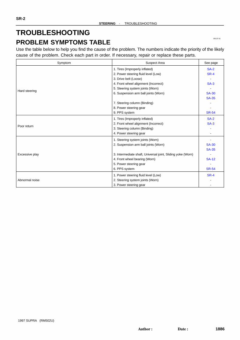
TROUBLESHOOTINGPROBLEM SYMPTOMS TABLEUse the table below to help you find the cause of the problem. The numbers indicate the priority of the likelycause of the problem. Check each part in order. If necessary, repair or replace these parts.
Symptom Suspect Area See page
Hard steering
1. Tires (Improperly inflated)
2. Power steering fluid level (Low)
3. Drive belt (Loose)
4. Front wheel alignment (Incorrect)
5. Steering system joints (Worn)
6. Suspension arm ball joints (Worn)
7. Steering column (Binding)
8. Power steering gear
9. PPS system
SA-2
SR-4
-
SA-3
-
SA-30
SA-35
-
-
SR-54
Poor return
1. Tires (Improperly inflated)
2. Front wheel alignment (Incorrect)
3. Steering column (Binding)
4. Power steering gear
SA-2
SA-3
-
-
Excessive play
1. Steering system joints (Worn)
2. Suspension arm ball joints (Worn)
3. Intermediate shaft, Universal joint, Sliding yoke (Worn)
4. Front wheel bearing (Worn)
5. Power steering gear
6. PPS system
-
SA-30
SA-35
-
SA-12
-
SR-54
Abnormal noise
1. Power steering fluid level (Low)
2. Steering system joints (Worn)
3. Power steering gear
SR-4
-
-

SR13U-01
R07281
Normal Abnormal
-STEERING POWER STEERING FLUIDSR-3
1887Author: Date:
1997 SUPRA (RM502U)
POWER STEERING FLUIDBLEEDING1. CHECK FLUID LEVEL
(See page SR-4 )2. JACK UP FRONT OF VEHICLE AND SUPPORT IT
WITH STANDS3. TURN STEERING WHEELWith the engine stopped, turn the steering wheel slowly fromlock to lock several times.NOTICE:Take care that some fluid remains in the oil reservoir.4. LOWER VEHICLE5. START ENGINERun the engine at idle for a few minutes.6. TURN STEERING WHEEL(a) With the engine at idling, turn the steering wheel to left or
right full lock and keep it there for 2-3 seconds, then turnthe wheel to the opposite full lock and keep it there for 2-3seconds.
(b) Repeat (a) several times.7. STOP ENGINE8. CHECK FOR FOAMING OR EMULSIFICATIONIf the system has to be bled twice specifically because of foam-ing or emulsification, check for fluid leaks in the system.9. CHECK FLUID LEVEL
(See page SR-4 )

SR13V-01
R00441
R07281
Normal Abnormal
R10552
5 mm (0.20 in.) or less
Engine Idling Engine Stopped
SR-4-STEERING POWER STEERING FLUID
1888Author: Date:
1997 SUPRA (RM502U)
INSPECTION1. CHECK FLUID LEVEL(a) Keep the vehicle level.
With the engine stopped, check the fluid level in the oilreservoir.
If necessary, add fluid.Fluid: ATF DEXRON ® II or III
HINT:Check that the fluid level is within the HOT LEVEL range on thedipstick of the reservoir cap. If the fluid is cold, check that it iswithin the COLD LEVEL range.(b) Start the engine and run it at idle.(c) Turn the steering wheel from lock to lock several times to
boost fluid temperature.Fluid temperature: 80 °C (176°F)
(d) Check for foaming or emulsification.If there is foaming or emulsification, bleed power steering sys-tem.(See page SR-3 )
(e) With the engine idling, measure the fluid level in the oilreservoir.
(f) Stop the engine.(g) Wait a few minutes and remeasure the fluid level in the
reservoir.Maximum fluid level rise: 5mm (0.20 in.)
If a problem is found, bleed power steering system.(See page SR-3 )(h) Check the fluid level.

Z16580
INSST SST
OUT
Pressure Feed TubeAttachment
PS Vane Pump
2JZ-GE: 2JZ-GTE:
AttachmentAttachmentPS Vane PumpAttachment
Pressure Feed Tube
-STEERING POWER STEERING FLUIDSR-5
1889Author: Date:
1997 SUPRA (RM502U)
2. CHECK STEERING FLUID PRESSURE(a) Disconnect the pressure feed tube from the PS vane
pump. (See page SR-26 )
(b) Connect SST over a new gasket, as shown below.SST 09640-10010 (09641-01010, 09641-01030,
09641-01060)NOTICE:Check that the valve of the SST is in the open position.
(c) Bleed the power steering system.(See page SR-3 )
(d) Start the engine and run it at idle.(e) Turn the steering wheel from lock to lock several times to
boost fluid temperature.Fluid temperature: 80 °C (176°F)
Z15498
PS Gear
OilReservior
PS VanePump
Closed
SST
Z15499
PS Gear
OilReservior
PS VanePump
SST
Open
Z15500
PS Gear
OilReservior
PS VanePump
SST
Open
SR-6-STEERING POWER STEERING FLUID
1890Author: Date:
1997 SUPRA (RM502U)
(f) With the engine idling, close the valve of the SST and ob-serve the reading on the SST.Minimum fluid pressure:7,355 kPa (75 kgf.cm 2, 1,067 psi)
NOTICE: Do not keep the valve closed for more than 10 se-
conds. Do not let the fluid temperature become too high.
(g) With the engine idling, open the valve fully.(h) Measure the fluid pressure at engine speeds of 1,000 rpm
and 3,000 rpm.Difference fluid pressure:490 kPa (5 kgf.cm 2, 71 psi) or less
NOTICE:Do not turn the steering wheel.
(i) With the engine idling and valve fully opened, turn thewheel to full lock.Minimum fluid pressure:7,355 kpa (75 kgf,cm 2, 1,067 psi)
NOTICE: Do not maintain lock position for more than 10 se-
conds. Do not let the fluid temperature become too high.
(j) Disconnect the SST.(k) Connect the pressure feed tube.
(See page SR-34 )(l) Bleed the power steering system.
(See page SR-3 )
Z13450
2JZ-GE:
2JZ-GTE:
SR0CK-01
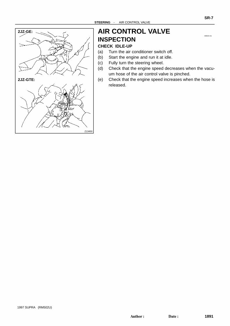
-STEERING AIR CONTROL VALVESR-7
1891Author: Date:
1997 SUPRA (RM502U)
AIR CONTROL VALVEINSPECTIONCHECK IDLE-UP(a) Turn the air conditioner switch off.(b) Start the engine and run it at idle.(c) Fully turn the steering wheel.(d) Check that the engine speed decreases when the vacu-
um hose of the air control valve is pinched.(e) Check that the engine speed increases when the hose is
released.

SR13W-01
R09732
W00625
PPS SolenoidConnector
SR-8-STEERING STEERING WHEEL
1892Author: Date:
1997 SUPRA (RM502U)
STEERING WHEELINSPECTION1. CHECK STEERING WHEEL FREEPLAYWith the vehicle stopped and tires pointed straight ahead, rockthe steering wheel gently back and forth with light finger pres-sure.Freeplay should not exceed the maximum.
Maximum freeplay: 30 mm (1.18 in.)
2. CHECK STEERING EFFORT(a) Center the steering wheel.(b) Remove the steering wheel pad.
(See page SR-1 1)(c) Start the engine and run it at idle.(d) Measure the steering effort in both directions.
Reference (Maximum): 6.9 N·m (70 kgf·cm, 61 in.·lbf)If steering effort is excessive, repair the power steering unit.HINT:Be sure to consider the tire type, pressure and contact surfacebefore making your diagnosis.
(e) Disconnect the PPS solenoid connector.(f) Measure the steering effort in both directions and check
that the steering effort exceeds the reference value in (d),and that the power assist is operating.
If steering effort is not heavier than (d), check the solenoid.(g) Connect the connector.(h) Torque the steering wheel set nut.
Torque: 35 N·m (360 kgf·cm, 26 ft·lbf)(i) Install the steering wheel pad.
(See page SR-21 )
SR13X-01
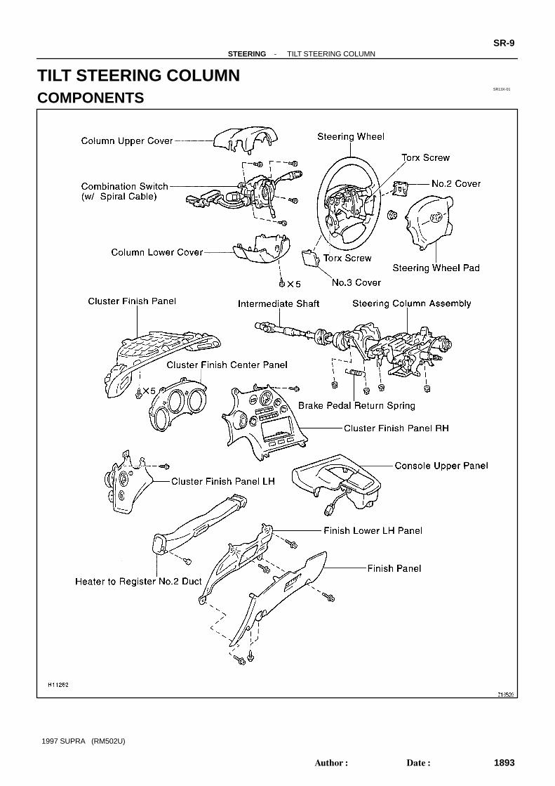
-STEERING TILT STEERING COLUMNSR-9
1893Author: Date:
1997 SUPRA (RM502U)
TILT STEERING COLUMNCOMPONENTS

SR-10-STEERING TILT STEERING COLUMN
1894Author: Date:
1997 SUPRA (RM502U)

SR13Y-01
-STEERING TILT STEERING COLUMNSR-1 1
1895Author: Date:
1997 SUPRA (RM502U)
REMOVAL1. REMOVE STEERING WHEEL PADNOTICE:If the airbag connector is disconnected with the ignitionswitch at ON or ACC, DTCs will be recorded. Never use air-bag parts from another vehicle. When replacing parts, re-place with new parts.
(a) Place the front wheels facing straight ahead.(b) Using a torx socket wrench, loosen the 2 torx screws.HINT:Loosen the 2 screws until the groove along the screw circumfer-ence catches on the screw case.
(c) Pull the pad out from the steering wheel and disconnectthe airbag connector.
CAUTION:When storing the pad, keep the upper surface of the padfacing upward. Never disassemble the pad.NOTICE:When removing the pad, take care not to pull the airbagwire harness.
2. REMOVE STEERING WHEEL(a) Disconnect the connector.(b) Remove the wheel set nut.(c) Place matchmarks on the wheel and main shaft.(d) Using SST, remove the wheel.
SST 09950-50010 (09951-05010, 09952-05010,09953-05020, 09954-05020)
3. REMOVE UPPER AND LOWER COLUMN COVERSRemove 5 screws.

R07283
A B
Matchmarks
SR-12-STEERING TILT STEERING COLUMN
1896Author: Date:
1997 SUPRA (RM502U)
4. REMOVE THESE PARTS:(See page BO-54 )
(a) Console upper panel(b) Cluster finish panel(c) Cluster finish panel RH(d) Cluster finish panel LH(e) Cluster finish center panel(f) Finish panel(g) Finish lower LH panel(h) Heater to register No.2 duct5. REMOVE COMBINATION SWITCH WITH SPIRAL
CABLE(a) Remove the 4 screws.(b) Disconnect the connectors and airbag connector.6. REMOVE SPIRAL CABLE
(See page BE-16 )NOTICE:Do not disassemble the cable or apply oil to it.7. DISCONNECT INTERMEDIATE SHAFT(a) Place matchmarks on the intermediate shaft and control
valve shaft.(b) Loosen bolt B and remove bolt A.8. REMOVE STEERING COLUMN ASSEMBLY(a) Remove the brake pedal return spring.(b) Disconnect the connectors.(c) Loosen the hole cover clamp.(d) Remove the 4 column assembly set nuts.

SR13Z-01
R07558
Matchmarks
R07559
ScrewExtractor
-STEERING TILT STEERING COLUMNSR-13
1897Author: Date:
1997 SUPRA (RM502U)
DISASSEMBLYNOTICE:When using a vise, do not overtighten it.1. REMOVE IGNITION KEY CYLINDER ILLUMINATION2. REMOVE INTERMEDIATE SHAFTRemove the bolt.
3. REMOVE SLIDING YOKE AND SHAFT THRUST STOP-PER
(a) Remove the bolt.(b) Shift the stopper.(c) Place matchmarks on the sliding yoke and main shaft.4. REMOVE COLUMN LOWER COVERLoosen the clamp.5. REMOVE COLUMN UPPER BRACKET AND COLUMN
UPPER CLAMP(a) Using a centering punch, mark the center of the 2 ta-
pered-head bolts.(b) Using a 4 - 5 mm (0.16 - 0.20 in.) drill, drill into the 2 ta-
pered-head bolts.
(c) Using a screw extractor, remove the 2 tapered-headbolts.
6. REMOVE WIRING HARNESS CLAMP AND COLUMNPROTECTOR
Remove the 2 screws.7. REMOVE COMPRESSION SPRING(a) Using a torx socket wrench, remove the screw.(b) Remove the 2 bushings from the spring.8. REMOVE 3 TENSION SPRINGS9. REMOVE STEERING DAMPERRemove the 2 bolts.10. REMOVE TURN SIGNAL BRACKETRemove the 2 bolts.

Z13448
HexagonWrench
R09495
Nut
Bolt
SST
Plate WasherTilt No.2 Bolt
R09496
SST
SST
SR-14-STEERING TILT STEERING COLUMN
1898Author: Date:
1997 SUPRA (RM502U)
11. Tilt Lever Side:REMOVE TILT LEVER RETAINER
Remove the nut and E-ring.12. Tilt Sub Lever Side:
REMOVE TILT LEVER RETAINER(a) Using a hexagon wrench (4 mm) to hold the tilt memory
bolt, remove the nut.(b) Remove the nut, washer and bolt.(c) Remove the nut, E-ring and spacer.(d) Remove the collar.(e) Temporarily install the bolt, washer and nut.13. REMOVE 2 TILT PAWL STOPPERS14. REMOVE 2 TILT PAWLS(a) Remove the bolt, nut and washer.(b) Remove the tilt lever assembly set bolt.15. REMOVE TILT LEVER, TILT SUB LEVER, TILT LEVER
ASSEMBLY AND TILT LEVER LOCK SHAFT16. REMOVE TILT MEMORY BOLT AND SQUARE NUTUsing a hexagon wrench (4 mm), remove the bolt.
17. REMOVE COLUMN UPPER TUBE WITH MAIN SHAFTASSEMBLY
(a) Set SST, the nut (10 mm nominal diameter, 1.25 mmpitch), plate washer (36 mm outer diameter) and bolt (10mm nominal diameter, 1.25 mm pitch, 50 mm length) tothe tilt No.2 bolt, as shown.SST 09910-00015 (09911-0001 1, 09912-00010)Reference:Nut 90170-10004Plate washer 90201-10201Bolt 91111-51050
(b) Remove the 2 tilt No.2 bolts by using the sliding hammeron SST.
(c) Remove the upper tube with the shaft assembly from thecolumn lower tube.
18. REMOVE MAIN SHAFT ASSEMBLY(a) Using SST, compress the compression spring.
SST 09950-40010 (09957-04010, 09958-04010)NOTICE:Do not bend the universal joint of the main shaft assemblymore than 20 °.(b) Using a snap ring expander, remove the snap ring.(c) Remove the main shaft assembly from the upper tube.(d) Remove the compression spring, thrust collar and bear-
ing from the main shaft.
-STEERING TILT STEERING COLUMNSR-15
1899Author: Date:
1997 SUPRA (RM502U)
19. REMOVE MAIN SHAFT COLLAR AND MAIN SHAFTBUSHING STOPPER
SR140-01
R11204
R11203
Screwdriver
Key Cylinder
R01835
SR-16-STEERING TILT STEERING COLUMN
1900Author: Date:
1997 SUPRA (RM502U)
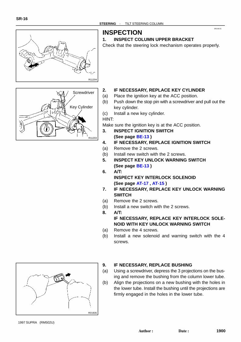
INSPECTION1. INSPECT COLUMN UPPER BRACKETCheck that the steering lock mechanism operates properly.
2. IF NECESSARY, REPLACE KEY CYLINDER(a) Place the ignition key at the ACC position.(b) Push down the stop pin with a screwdriver and pull out the
key cylinder.(c) Install a new key cylinder.HINT:Make sure the ignition key is at the ACC position.3. INSPECT IGNITION SWITCH
(See page BE-13 )4. IF NECESSARY, REPLACE IGNITION SWITCH(a) Remove the 2 screws.(b) Install new switch with the 2 screws.5. INSPECT KEY UNLOCK WARNING SWITCH
(See page BE-13 )6. A/T:
INSPECT KEY INTERLOCK SOLENOID(See page AT-17 , AT-15 )
7. IF NECESSARY, REPLACE KEY UNLOCK WARNINGSWITCH
(a) Remove the 2 screws.(b) Install a new switch with the 2 screws.8. A/T:
IF NECESSARY, REPLACE KEY INTERLOCK SOLE-NOID WITH KEY UNLOCK WARNING SWITCH
(a) Remove the 4 screws.(b) Install a new solenoid and warning switch with the 4
screws.
9. IF NECESSARY, REPLACE BUSHING(a) Using a screwdriver, depress the 3 projections on the bus-
ing and remove the bushing from the column lower tube.(b) Align the projections on a new bushing with the holes in
the lower tube. Install the bushing until the projections arefirmly engaged in the holes in the lower tube.

SR141-01
R09496
SST
SST
R07549
Hollow-Tipped
-STEERING TILT STEERING COLUMNSR-17
1901Author: Date:
1997 SUPRA (RM502U)
REASSEMBLYNOTICE:When using a vise, do not overtighten it.1. COAT MOLYBDENUM DISULFIDE LITHIUM BASE
GREASE(See page SR-9 )
2. INSTALL MAIN SHAFT BUSHING STOPPER ANDMAIN SHAFT COLLAR
3. INSTALL MAIN SHAFT ASSEMBLY(a) Install a new bearing.(b) Install the thrust collar and compression spring to the
shaft assembly.(c) Install the main shaft into the column upper tube.(d) Using SST, compress the compression spring.
SST 09950-40010 (09957-04010, 09958-04010)NOTICE:Do not bend the universal joint of the main shaft assemblymore than 20 °.(e) Using a snap ring expander, install a new snap ring.
4. SELECT 2 TILT NO.2 BOLTSSelect the bolt with the hollow-tipped thread end when the col-umn upper tube mark is 1, and the bolt with the plain thread endwhen the mark is 2.NOTICE:Select the bolt type to match each number marked in thesquares on the upper tube.5. INSTALL COLUMN UPPER TUBE WITH MAIN SHAFT
ASSEMBLY(a) Install the upper tube with the shaft assembly into the low-
er tube.

R07550
Z13449
Nut
Bolt
R07552
SR-18-STEERING TILT STEERING COLUMN
1902Author: Date:
1997 SUPRA (RM502U)
(b) Using a vise, press in the 2 tilt No.2 bolts.
6. INSTALL TILT MEMORY BOLT AND SQUARE NUT(a) Apply sealant to 2 or 3 threads of the bolt.
Sealant:Part No. 08833-00080, THREE BOND 1344,LOCTITE 242 or equivalent.
(b) Using a hexagon wrench (4 mm), install the shorter sideof the bolt to the nut.Torque: 6.4 N·m (65 kgf·cm, 56 in.·lbf)
7. INSTALL TILT LEVER LOCK SHAFT, TILT LEVER AS-SEMBLY, TILT SUB LEVER AND TILT LEVER
Temporarily tighten the tilt lever assembly set bolt.8. INSTALL 2 TILT PAWLS(a) Temporarily install the bolt, washer and nut.HINT:Install the pin of the pawl into the long hole of the tilt lever / tiltsub lever.(b) Torque the tilt lever assembly set bolt.
Torque: 4.7 N·m (48 kgf·cm, 42 in.·lbf)
9. ENGAGE AND ADJUST 2 TILT PAWLS(a) Engage the tilt sub lever side pawl to the center of the
ratchet.(b) Using a spanner (17 mm), while turning the collar, com-
pletely engage the tilt lever side pawl to the ratchet.NOTICE: Do not turn the collar after the tilt lever side pawl is en-
gaged. Keep the bolt and nut temporarily tightened.

Z16582
Tilt Pawl Stopper
Tilt Pawl Alignment Marks
R07555
-STEERING TILT STEERING COLUMNSR-19
1903Author: Date:
1997 SUPRA (RM502U)
10. SELECT 2 TILT PAWL STOPPERS(a) With the tilt pawl and ratchet engaged, install the stopper.(b) Check that the alignment marks on the stopper and pawl
align when the stopper is lightly rotated to the pawl side.(c) If the alignment marks do not align, select pawl stoppers
according to the following table.
Tilt sub lever side Tilt lever sideDimension ”A”
mm (in.)
1 A12.68 - 12.74
(0.4992 - 0.5016)
2 B12.61 - 12.67
(0.4965 - 0.4988)
3 C12.54 - 12.60
(0.4937 - 0.4961)
4 D12.47 - 12.53
(0.4909 - 0.4933)
5 E12.40 - 12.46
(0.4882 - 0.4906)
6 F12.33 - 12.39
(0.4854 - 0.4878)
7 G12.26 - 12.32
(0.4827 - 0.4850)
(d) After selecting the stopper, check that on both sides thepawl and ratchet are fully engaged.
11. INSTALL 2 TILT PAWL STOPPERS
12. Tilt Sub Lever Side:INSTALL TILT LEVER RETAINER
(a) Remove the bolt and nut.NOTICE:Take care not to turn the collar of the tilt sub lever side pawl.(b) Install the collar to the tilt memory bolt.(c) Install the retainer.(d) Install the bolt and washer, and torque the nut.HINT:Install the bolt so that the groove in the bolt shaft faces upward.
Torque: 5.9 N·m (60 kgf·cm, 52 in.·lbf)(e) Torque the nut of the tilt No.2 bolt side.
Torque: 15 N·m (150 kgf·cm, 11 ft·lbf)(f) Torque the nut of the memory bolt side.
Torque: 5.9 N·m (60 kgf·cm, 52 in.·lbf)(g) Install the spacer and a new E-ring.13. Tilt Lever Side:
INSTALL TILT LEVER RETAINER(a) Torque the nut.
Torque: 15 N·m (150 kgf·cm, 11 ft·lbf)

R07557
SR-20-STEERING TILT STEERING COLUMN
1904Author: Date:
1997 SUPRA (RM502U)
(b) Install a new E-ring.14. INSTALL TURN SIGNAL BRACKET(a) Apply sealant to 2 or 3 threads of the 2 bolts.
Sealant:Part No. 08833-00080, THREE BOND 1344,LOCTITE 242 or equivalent.
(b) Torque the 2 bolts.Torque: 8.8 N·m (90 kgf·cm, 78 in.·lbf)
15. INSTALL STEERING DAMPERTorque the 2 bolts.16. INSTALL 3 TENSION SPRINGS17. INSTALL COMPRESSION SPRING(a) Install the 2 bushings to the spring.(b) Apply sealant to 2 or 3 threads of the torx screw.
Sealant:Part No. 08833-00080, THREE BOND 1344,LOCTITE 242 or equivalent.
(c) Using a torx socket wrench, torque the screw.Torque: 6.4 N·m (65 kgf·cm, 56 in.·lbf)
18. INSTALL COLUMN PROTECTOR AND WIRING HAR-NESS CLAMP
Tighten the 2 screws.
19. INSTALL COLUMN UPPER BRACKET AND COLUMNUPPER CLAMP
Tighten 2 new tapered-head bolts until the bolt head breaks off.20. INSTALL COLUMN LOWER COVERTighten the clamp.21. INSTALL SHAFT THRUST STOPPER AND SLIDING
YOKE(a) Align the matchmarks on the yoke and main shaft.(b) Torque the bolt.
Torque: 35 N·m (360 kgf·cm, 26 ft·lbf)22. INSTALL INTERMEDIATE SHAFTTemporarily tighten the bolt.23. INSTALL IGNITION KEY CYLINDER ILLUMINATION24. CHECK TILT OPERATION

SR142-01
W02982
R07283
Matchmarks
A B
R05740
Red Mark
-STEERING TILT STEERING COLUMNSR-21
1905Author: Date:
1997 SUPRA (RM502U)
INSTALLATION1. INSTALL STEERING COLUMN ASSEMBLY(a) Torque the 4 column assembly set nuts.
Torque: 25 N·m (260 kgf·cm, 19 ft·lbf)(b) Connect the connectors.(c) Install the brake pedal return spring.(d) Tighten the hole cover clamp.
2. CONNECT INTERMEDIATE SHAFT(a) Align the matchmarks on the intermediate shaft and con-
trol valve shaft.(b) Torque the bolt A.
Torque: 35 N·m (360 kgf·cm, 26 ft·lbf)(c) Torque the bolt B.
Torque: 35 N·m (360 kgf·cm, 26 ft·lbf)3. INSTALL SPIRAL CABLE
(See page BE-16 )4. INSTALL COMBINATION SWITCH WITH SPIRAL
CABLE(a) Tighten the 4 screws.(b) Connect the connectors and airbag connector.5. INSTALL THESE PARTS:
(See page BO-59 )(a) Heater to Register No.2 duct(b) Finish lower LH panel(c) Finish panel(d) Cluster finish center panel(e) Cluster finish panel LH(f) Cluster finish panel RH(g) Cluster finish panel(h) Console upper panel6. INSTALL COLUMN UPPER AND LOWER COVERSTighten the 5 screws.
7. CENTER SPIRAL CABLE(a) Check that the front wheels are facing straight ahead.(b) Turn the spiral cable counterclockwise by hand until it be-
comes harder to turn the cable.(c) Rotate the spiral cable clockwise about 3 turns to align the
marks.HINT:The spiral cable will rotate about 3 turns to either left or right ofthe center.

SR-22-STEERING TILT STEERING COLUMN
1906Author: Date:
1997 SUPRA (RM502U)
8. INSTALL STEERING WHEEL(a) Align the matchmarks on the wheel and main shaft.(b) Torque the wheel set nut.
Torque: 35 N·m (360 kgf·cm, 26 ft·lbf)(c) Connect the connector.9. INSTALL STEERING WHEEL PADNOTICE:Make sure the pad is installed to the specified torque. If thepad has been dropped, or there are cracks, dents or otherdefects in the case or connector, replace the pad with a newone. When installing the pad, take care that the wiring doesnot interfere with other parts and is not pinched betweenother parts.(a) Connect the airbag connector.
(b) Install the pad after confirming that the circumference ofthe torx screw groove is caught on the screw case.
(c) Using a torx socket wrench, torque the 2 screws.Torque: 7.1 N·m (72 kgf·cm, 62 in.·lbf)
10. CHECK STEERING WHEEL CENTER POINT

SR143-01
Z18268
2JZ-GE:
PS Vane PumpAssembly
Oil Reservoir
Return Tube
Battery Clamp
Battery Cover
Terminal Terminal
Pressure Feed Tube
Air Control Valve
Gasket
Union Bolt
Drive Belt
Battery
Battery Carrier
Engine Under Coverx10
Non-reusable part
-STEERING POWER STEERING VANE PUMPSR-23
1907Author: Date:
1997 SUPRA (RM502U)
POWER STEERING VANE PUMPCOMPONENTS

Z18269
2JZ-GTE:
Battery Clamp
Battery Cover
Terminal Terminal
Battery
Pressure Feed Tube
GasketUnion Bolt
Drive Belt
Battery Carrier
Air Hose No.5
Oil Reservoir to Pump Hose
PS Vane Pump Assembly
Vane Pump Pulley
Engine Under Coverx10
Non-reusable part
SR-24-STEERING POWER STEERING VANE PUMP
1908Author: Date:
1997 SUPRA (RM502U)

Z19281
2JZ-GE and 2JZ-GTE:
Reservoir Cap
2JZ-GE:Oil Reservoir
2JZ-GTE:Suction Port Union
O-Ring
Flow Control Valve
Pressure PortUnion
Front Housing
Vane Pump Shaft
2JZ-GE:Vane Pump Pulley
O-Ring
Bearing Oil Seal
GasketSpring
O-Ring
Snap Ring
Snap Ring
O-Ring
Straight Pin
Rear Housing
Wave Washer
Side Plate
Cam RingVane Plate
Vane Pump Rotor
x10
Straight Pin
Non-reusable part: Power steering fluid
-STEERING POWER STEERING VANE PUMPSR-25
1909Author: Date:
1997 SUPRA (RM502U)

SR144-01
R06091
R07429
R07432
SR-26-STEERING POWER STEERING VANE PUMP
1910Author: Date:
1997 SUPRA (RM502U)
REMOVAL1. REMOVE ENGINE UNDER COVERRemove the 10 screws.2. REMOVE BATTERY(a) Disconnect the 2 terminals.(b) Remove the bolt, nut and battery clamp.(c) Remove the battery cover.(d) Remove the battery and battery carrier.3. 2JZ-GTE:
REMOVE AIR HOSE No.54. REMOVE DRIVE BELTLoosen the drive belt tension by turning the drive belt tensionerclockwise, and remove the drive belt.5. 2JZ-GTE:
DISCONNECT OIL RESERVOIR TO PUMP HOSERemove the clip and disconnect the hose.NOTICE:Take care not to spill fluid on the A/C compressor rotor.6. 2JZ-GE:
DISCONNECT RETURN TUBENOTICE:Take care not to spill fluid on the A/C compressor rotor.
7. 2JZ-GTE:REMOVE VANE PUMP PULLEY
Using SST to stop the pulley rotating, remove the nut.SST 09960-10010 (09962-01000, 09963-01000)
8. REMOVE PRESSURE FEED TUBEUsing a spanner (24 mm) to hold the pressure port union, re-move the union bolt and gasket.9. REMOVE PS VANE PUMP ASSEMBLYRemove the 2 pump assembly set bolts.

SR145-01
R06768
SST
R01151
Z06059
Vinyl Tape
-STEERING POWER STEERING VANE PUMPSR-27
1911Author: Date:
1997 SUPRA (RM502U)
DISASSEMBLYNOTICE:When using a vise, do not overtighten it.1. 2JZ-GE:
REMOVE VANE PUMP PULLEYUsing SST to stop the pulley rotating, remove the pulley set nut.
SST 09960-10010 (09962-01000, 09963-01000)
2. MEASURE PS VANE PUMP ROTATING TORQUE(a) Check that the pump rotates smoothly without abnormal
noise.(b) Temporarily install the pulley set nut, and using a torque
wrench, check the pump rotating torque.Rotating torque:0.2 N·m (2.5 kgf·cm, 2.2 in.·lbf) or less
3. 2JZ-GE:REMOVE OIL RESERVOIR
(a) Remove the 3 bolts.(b) Remove the O-ring from the reservoir.4. 2JZ-GTE:
REMOVE SUCTION PORT UNION(a) Remove the bolt.(b) Remove the O-ring from the union.5. REMOVE PRESSURE PORT UNION, FLOW CONTROL
VALVE AND SPRINGRemove the O-ring from the union.6. REMOVE REAR HOUSINGRemove the 2 bolts.7. REMOVE CAM RING, VANE PUMP ROTOR AND 10
VANE PLATESNOTICE:Be careful not to drop the vane plates.8. REMOVE 2 STRAIGHT PINS9. REMOVE GASKET
10. REMOVE VANE PUMP SHAFT WITH BEARING(a) Using snap ring pliers, remove the snap ring from the front
housing.(b) Wind vinyl tape on the serrated part of the shaft.(c) Using a press, press out the shaft with the bearing.

Z06062
SR-28-STEERING POWER STEERING VANE PUMP
1912Author: Date:
1997 SUPRA (RM502U)
11. REMOVE SIDE PLATE AND WAVE WASHER(a) Using a plastic hammer, tap the rear housing on the
shaded area untill the plate and washer come off.(b) Remove the 2 O-rings from the rear housing.
SR146-01
Z16583
Vane Pump Shaft
Bushing Front Housing
Z06061
Thickness
Height
Length
R10282
FeelerGauge
-STEERING POWER STEERING VANE PUMPSR-29
1913Author: Date:
1997 SUPRA (RM502U)
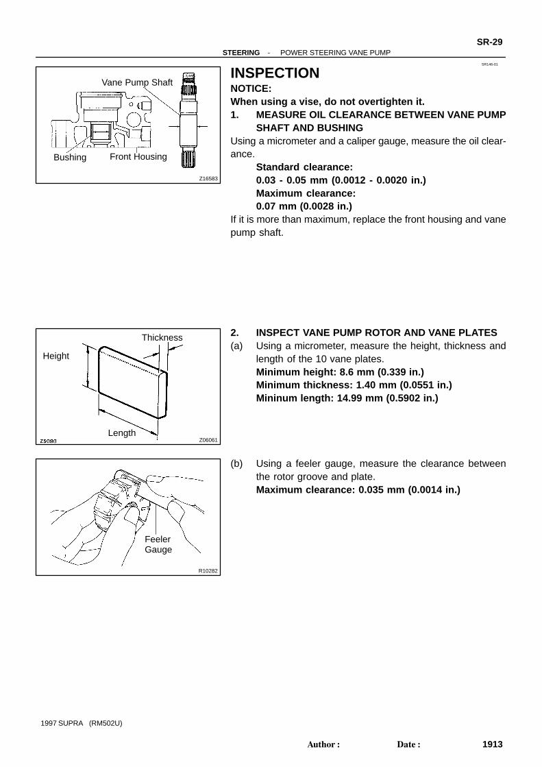
INSPECTIONNOTICE:When using a vise, do not overtighten it.1. MEASURE OIL CLEARANCE BETWEEN VANE PUMP
SHAFT AND BUSHINGUsing a micrometer and a caliper gauge, measure the oil clear-ance.
Standard clearance:0.03 - 0.05 mm (0.0012 - 0.0020 in.)Maximum clearance:0.07 mm (0.0028 in.)
If it is more than maximum, replace the front housing and vanepump shaft.
2. INSPECT VANE PUMP ROTOR AND VANE PLATES(a) Using a micrometer, measure the height, thickness and
length of the 10 vane plates.Minimum height: 8.6 mm (0.339 in.)Minimum thickness: 1.40 mm (0.0551 in.)Mininum length: 14.99 mm (0.5902 in.)
(b) Using a feeler gauge, measure the clearance betweenthe rotor groove and plate.Maximum clearance: 0.035 mm (0.0014 in.)

R13897Inscribed Mark
R07603
R07591
Compressed Air
R07600
InscribedMark
SR-30-STEERING POWER STEERING VANE PUMP
1914Author: Date:
1997 SUPRA (RM502U)
If it is more than the maximum, replace the plate and/or rotorwith one having the same mark stamped on the cam ring.
Inscribed mark:1, 2, 3, 4 or None
HINT:There are 5 vane plate lengths with the following rotor and camring marks:
Rotor and cam
ring mark
Vane plate part
number
Vane plate length
mm (in.)
None 44345-2601014.999-15.001
(0.59051-0.59059)
1 44345-2602014.997-14.999
(0.59043-0.59051)
2 44345-2603014.995-14.997
(0.59035-0.59043)
3 44345-2604014.993-14.995
(0.59027-0.59035)
4 44345-2605014.991-14.993
(0.59020-0.59027)
3. INSPECT FLOW CONTROL VALVE(a) Coat the valve with power steering fluid and check that it
falls smoothly into the valve hole by its own weight.
(b) Check the valve for leakage.Close one of the holes and apply 392 - 490 kPa (4 - 5 kgf/cm2, 57 - 71 psi) of compressed air into the opposite side,and confirm that air does not come out from the end holes.
If necessary, replace the valve with one having the same letteras inscribed on the front housing.
Inscribed mark:A, B, C, D, E or F

R08702
Calipers
Z08200
SST
Z06067
R13869
PressBearing
Removal Installation
-STEERING POWER STEERING VANE PUMPSR-31
1915Author: Date:
1997 SUPRA (RM502U)
4. INSPECT SPRINGUsing calipers, measure the free length of the spring.
Minimum free length: 33mm (1.30 in.)If it is not within the specification, replace the spring.
5. IF NECESSARY, REPLACE OIL SEAL(a) Using SST, tap out the oil seal.
SST 09631-10030NOTICE:Be careful not to damage the bushing of the front housing.
(b) Coat a new oil seal lip with power steering fluid.(c) Using a socket wrench (24 mm), press in the oil seal.NOTICE:Make sure to install the oil seal facing the correct direction.
6. IF NECESSARY, REPLACE BEARING(a) Using a press, press out the bearing.(b) Using a snap ring expander, remove the snap ring from
the vane pump shaft.NOTICE:Be careful not damage the vane pump shaft.(c) Using a snap ring expander, install a new snap ring.NOTICE:Be careful not damage the vane pump shaft.(d) Coat a new bearing with power steering fluid.(e) Using a press, press in the bearing.

SR147-01
Z06071
SST
Vinyl Tape
Z06072
Inscribed Mark
Z06073
InscribedMark
R01149
Round End
SR-32-STEERING POWER STEERING VANE PUMP
1916Author: Date:
1997 SUPRA (RM502U)
REASSEMBLYNOTICE:When using a vise, do not overtighten it.1. COAT WITH POWER STEERING FLUID
(See page SR-23 )2. INSTALL VANE PUMP SHAFT WITH BEARING(a) Wind vinyl tape on the serrated part of the shaft.(b) Using SST, press in the shaft with the bearing to the front
housing.SST 09608-04031
NOTICE:Be careful not to damage the oil seal.(c) Using snap ring pliers, install a new snap ring to the front
housing.3. INSTALL STRAIGHT PINSUsing a plastic hammer, drive in 2 new straight pins to the fronthousing.
4. INSTALL CAM RINGAlign the holes of the ring and straight pins, and install the ringwith the inscribed mark facing outward.
5. INSTALL VANE PUMP ROTORInstall the rotor with the inscribed mark facing outward.
6. INSTALL 10 VANE PLATESInstall the plate with the round end facing outward.7. INSTALL GASKETInstall a new gasket to the front housing.8. INSTALL SIDE PLATEAlign the holes of the plate and straight pins.

R01174
R06769
SST
-STEERING POWER STEERING VANE PUMPSR-33
1917Author: Date:
1997 SUPRA (RM502U)
9. INSTALL WAVE WASHERInstall the washer so that its protrusions fit into the slots in theside plate.10. INSTALL REAR HOUSING(a) Coat 2 new O-rings with power steering fluid and install
them to the housing.(b) Torque the 2 bolts.
Torque: 17 N·m (170 kgf·cm, 12 ft·lbf)11. INSTALL SPRING, FLOW CONTROL VALVE AND
PRESSURE PORT UNION(a) Coat a new O-ring with power steering fluid and install it
to the union.(b) Torque the union.
Torque: 83 N·m (850 kgf·cm, 61 ft·lbf)12. 2JZ-GTE:
INSTALL SUCTION PORT UNION(a) Coat a new O-ring with power steering fluid and install it
to the union.(b) Torque the bolt.
Torque: 13 N·m (130 kgf·cm, 9 ft·lbf)13. 2JZ-GE:
INSTALL OIL RESERVOIR(a) Coat a new O-ring with power steering fluid and install it
to the reservoir.(b) Torque the 3 bolts.
Torque:Front side bolt: 13 N·m (130 kgf·cm, 9 ft·lbf)Rear side bolts: 17 N·m (170 kgf·cm, 12 ft·lbf)
14. MEASURE PS VANE PUMP ROTATING TORQUE(See page SR-27 )
15. 2JZ-GE:INSTALL VANE PUMP PULLEY
Using SST to stop the pulley rotating, torque the nut.SST 09960-10010 (09962-01000, 09963-01000)Torque: 43 N·m (440 kgf·cm, 32 ft·lbf)

SR148-01
Z09176
Stopper
R07429
R06091
SR-34-STEERING POWER STEERING VANE PUMP
1918Author: Date:
1997 SUPRA (RM502U)
INSTALLATION1. INSTALL PS VANE PUMP ASSEMBLYTorque the 2 bolts.
Torque:RH side bolt: 39 N·m (400 kgf·cm, 29 ft·lbf)LH side bolt: 58 N·m (590 kgf·cm, 42 ft·lbf)
2. CONNECT PRESSURE FEED TUBEUsing a spanner (24 mm) to hold the pressure port union,torque the union bolt with a new gasket.HINT:Make sure that the stopper of the tube is touching the PS vanepump assembly as shown, before torquing the union bolt.
Torque: 49 N·m (500 kgf·cm, 36 ft·lbf)
3. 2JZ-GTE:INSTALL VANE PUMP PULLEY
Using SST to stop the pulley rotating, torque the nut.SST 09960-10010 (09962-01000, 09663-01000)Torque: 43 N·m (440 kgf·cm, 32 ft·lbf)
4. 2JZ-GE:CONNECT RETURN TUBE
5. 2JZ-GTE:CONNECT OIL RESERVOIR TO PUMP HOSE
Connect the hose and install the clip.6. INSTALL DRIVE BELTLoosen the drive belt tension by turning the drive belt tensionerclockwise, and install the drive belt.7. 2JZ-GTE:
INSTALL AIR HOSE No.58. INSTALL BATTERY(a) Install the battery carrier and battery.(b) Install the battery cover.(c) Install the battery clamp with bolt and nut.(d) Connect the 2 terminals.9. INSTALL ENGINE UNDER COVERInstall the 10 screws.10. BLEED POWER STEERING SYSTEM
(See page SR-3 )
SR149-01
R11266
Cotter Pin
Union Bolt
GasketReturn Tube
Union Bolt
Intermediate Shaft
Gasket
Pressure Feed Tube
Power Steering GearAssembly PPS Solenoid Connector
Rack Housing Bracket
Rack Housing Grommet
Cotter Pin
Front Suspension Member Protector
Engine Under Cover
x10
Non-reusable part
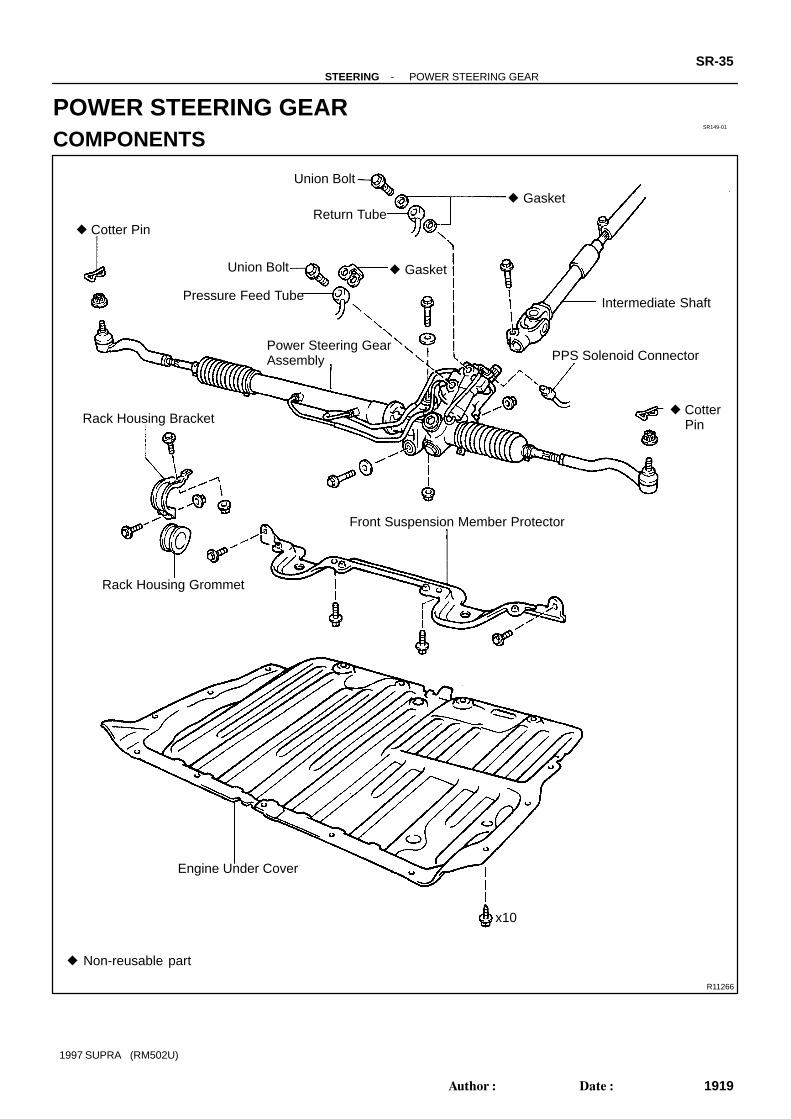
-STEERING POWER STEERING GEARSR-35
1919Author: Date:
1997 SUPRA (RM502U)
POWER STEERING GEARCOMPONENTS

SR-36-STEERING POWER STEERING GEAR
1920Author: Date:
1997 SUPRA (RM502U)

Z18140
Union Seat
Union Bolt
Gasket
Union Bolt
Gasket
Turn Pressure Tube
Dust Cover
Control Valve Housing
Pressure ControlValve Assembly
O-Ring
Oil Seal
O-Ring
Bearing
Teflon Ring
Connector Bracket
Solenoid Valve
Control Valve Assembly
Teflon Ring
O-Ring
Oil Seal
Bearing
Rack Housing
Non-reusable partMolybdenum disulfide lithium base greasePower Steering fluid
-STEERING POWER STEERING GEARSR-37
1921Author: Date:
1997 SUPRA (RM502U)

SR14A-01
SR-38-STEERING POWER STEERING GEAR
1922Author: Date:
1997 SUPRA (RM502U)
REMOVAL1. PLACE FRONT WHEELS FACING STRAIGHT AHEAD2. REMOVE STEERING WHEEL PAD
(See page SR-1 1)3. REMOVE STEERING WHEEL
(See page SR-1 1)4. REMOVE ENGINE UNDER COVERRemove the 10 bolts.5. REMOVE FR SUSPENSION MEMBER PROTECTORRemove the 4 bolts.6. DISCONNECT INTERMEDIATE SHAFT
(See page SR-1 1)7. DISCONNECT RH AND LH TIE ROD ENDS
(See page SA-12 )8. DISCONNECT PRESSURE FEED TUBERemove the union bolt and gasket.9. DISCONNECT RETURN TUBERemove the union bolt and 2 gaskets.10. DISCONNECT PPS SOLENOID CONNECTOR11. REMOVE RACK HOUSING BRACKET AND GROMMETRemove the 2 bolts and nuts.12. REMOVE PS GEAR ASSEMBLYRemove the 2 bolts and nuts.

SR14B-01
R06961
SST
R07510
SST
SR4371Matchmarks
Z06090
Chisel
R07107SST
-STEERING POWER STEERING GEARSR-39
1923Author: Date:
1997 SUPRA (RM502U)
DISASSEMBLYNOTICE:When using a vise, do not overtighten it.1. SECURE PS GEAR ASSEMBLY IN VISEUsing SST, secure the gear assembly in a vise.
SST 09612-00012
2. REMOVE 2 TURN PRESSURE TUBES(a) Remove the union bolt and 2 gaskets.(b) Using SST, remove the tube.
SST 09633-00020(c) Remove the 2 union seats from the rack housing.
3. REMOVE RH AND LH TIE ROD ENDS AND LOCKNUTS
Place matchmarks on the tie rod end and rack end, and loosenthe lock nut.4. REMOVE RH AND LH CLIPS, RACK BOOTS AND
CLAMPSNOTICE: Be careful not to damage the boot. Mark the RH and LH boots.
5. REMOVE RH AND LH RACK ENDS AND CLAW WASH-ERS
(a) Using a chisel and a hammer, unstake the washer.NOTICE:Avoid any impact to the steering rack.
(b) Using a spanner (22 mm) to hold the steering rack and us-ing SST, remove the rack end.SST 09922-10010
NOTICE: Use SST 09922-10010 in the direction shown in the il-
lustration. Mark the RH and LH rack ends.

R07108
SST
R07439
SST
Self-LockingNut
R07336
Vinyl Tape
R07099
Vinyl Tape
SR-40-STEERING POWER STEERING GEAR
1924Author: Date:
1997 SUPRA (RM502U)
6. REMOVE RACK GUIDE SPRING CAP LOCK NUTUsing SST, remove the nut.
SST 09922-10010NOTICE:Use SST 09922-10010 in the direction shown in the illustra-tion.7. REMOVE RACK GUIDE SPRING CAP, RACK GUIDE
SPRING, RACK GUIDE AND RACK GUIDE SEATUsing a hexagon wrench (24 mm), remove the cap.8. REMOVE RACK HOUSING CAP
9. REMOVE SELF- LOCKING NUT, BEARING ANDSPACER
Using SST to stop the control valve shaft rotating, remove thenut.
SST 09616-0001010. REMOVE DUST COVER
11. REMOVE CONTROL VALVE HOUSING WITH CON-TROL VALVE ASSEMBLY
(a) To prevent oil seal lip damage, wind vinyl tape on the ser-rated part of the control valve shaft.
(b) Using a hexagon wrench (6 mm), remove the 2 bolts.(c) Remove the O-ring from the housing.
12. REMOVE CONTROL VALVE ASSEMBLYUsing a plastic hammer, tap out the control valve.NOTICE:Be careful not to damage the oil seal lip.13. REMOVE CYLINDER END STOPPER AND 2 SPACERSUsing snap ring pliers, remove the snap ring from the rack hous-ing.

R07362
Press
Socket Wrench
Extension Bar
W00208
Press
SST
Spacer
SST
Oil Seal
-STEERING POWER STEERING GEARSR-41
1925Author: Date:
1997 SUPRA (RM502U)
14. REMOVE STEERING RACK AND OIL SEAL(a) Using an extension bar or brass bar and a press, press
out the rack with the oil seal.NOTICE:Take care not to drop the rack.(b) Remove the oil seal from the rack.
15. REMOVE OIL SEAL AND SPACERUsing SST, press out the oil seal and spacer.
SST 09950-60010 (09951-00280),09950-70010 (09951-07200)

SR14C-01
R10072
R07288
A
B
C
Bearing
SST
R07109
Cutouts
SST
Oil Seal
W00209
Press
SST
Oil SealSST
W00210
SST
Bearing
SR-42-STEERING POWER STEERING GEAR
1926Author: Date:
1997 SUPRA (RM502U)
INSPECTIONNOTICE:When using a vise, do not overtighten it.1. INSPECT STEERING RACK(a) Using a dial indicator, check the rack for runout and for
teeth wear or damage.Maximum runout: 0.30mm (0.018 in.)
(b) Check the back surface for wear or damage.
2. IF NECESSARY, REPLACE OIL SEAL AND BEARING(a) Set SST to the rack housing, as shown.
SST 09612-30012(b) Turn A clockwise and engage the tips of C on the bearing.(c) Using a spanner (8 mm), keep A fixed while turning nut B
clockwise, and remove the bearing.NOTICE:Be careful not to damage the rack housing.
(d) Using SST, remove the oil seal from the rack housing.SST 09612-30012
NOTICE:Be careful not to damage the rack housing.HINT:When using SST, apply the tips of SST to the cutouts in the rackhousing.
(e) Coat a new oil seal lip with power steering fluid.(f) Using SST, press in the oil seal.
SST 09950-60010 (09951-00280, 09951-00390,09952-06010), 09950-70010 (09951-07100)
NOTICE:Make sure to install the oil seal facing the correct direction.
(g) Using SST, press in the bearing.SST 09950-60010 (09951-00460),
09950-70010 (09951-07100)

W00211
SST
Oil Seal
Bearing
W00212
SST
Oil Seal Oil Seal
W00213
SST
Bearing
R10955
R06172
-STEERING POWER STEERING GEARSR-43
1927Author: Date:
1997 SUPRA (RM502U)
3. IF NECESSARY, REPLACE OIL SEAL AND BEARING(a) Using SST, press out the oil seal with the bearing from the
control valve housing.SST 09950-60010 (09951-00240),
09950-70010 (09951-07100)
(b) Coat a new oil seal lip with power steering fluid.(c) Using SST, press in the oil seal.
SST 09950-60010 (09951-00320),09950-70010 (09951-07200)
NOTICE:Make sure to install the oil seal facing the correct direction.
(d) Using SST, press in the bearing.SST 09950-60010 (09951-00340),
09950-70010 (09951-07200)
4. IF NECESSARY, REPLACE TEFLON RING AND O-RING
(a) Using a screwdriver, remove the teflon ring and O-ringfrom the steering rack.
NOTICE:Be careful not to damage the groove of the ring.(b) Coat a new O-ring with power steering fluid and install it.
(c) Expand a new teflon ring with your fingers.NOTICE:Be careful not to overexpand the ring.
Z06082
R11205
Screwdriver
Z06085
R11268
Screwdriver
SR-44-STEERING POWER STEERING GEAR
1928Author: Date:
1997 SUPRA (RM502U)
(d) Coat the ring with power steering fluid.(e) Install the ring to the rack, and snug it down with your fin-
gers.
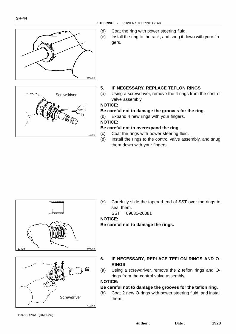
5. IF NECESSARY, REPLACE TEFLON RINGS(a) Using a screwdriver, remove the 4 rings from the control
valve assembly.NOTICE:Be careful not to damage the grooves for the ring.(b) Expand 4 new rings with your fingers.NOTICE:Be careful not to overexpand the ring.(c) Coat the rings with power steering fluid.(d) Install the rings to the control valve assembly, and snug
them down with your fingers.
(e) Carefully slide the tapered end of SST over the rings toseal them.SST 09631-20081
NOTICE:Be careful not to damage the rings.
6. IF NECESSARY, REPLACE TEFLON RINGS AND O-RINGS
(a) Using a screwdriver, remove the 2 teflon rings and O-rings from the control valve assembly.
NOTICE:Be careful not to damage the grooves for the teflon ring.(b) Coat 2 new O-rings with power steering fluid, and install
them.

-STEERING POWER STEERING GEARSR-45
1929Author: Date:
1997 SUPRA (RM502U)
(c) Expand 2 new teflon rings with your fingers.NOTICE:Be careful not to overexpand the teflon rings.(d) Coat the rings with power steering fluid.(e) Install the rings to the valve assembly, and snug them
down with your fingers.(f) Carefully slide the tapered end of SST over the teflon
rings to seal them.SST 09631-32020
NOTICE:Be careful not to damage the teflon rings.7. IF NECESSARY, REPLACE PRESSURE CONTROL
VALVE ASSEMBLY(a) Using a hexagon wrench (6 mm), remove the 3 bolts and
connector bracket.(b) Remove the 3 O-rings from the control valve housing.(c) Coat 3 new O-rings with power steering fluid, and install
them.(d) Using a hexagon wrench (6 mm), install a new pressure
control valve and connector bracket with the 3 bolts.Torque: 18 N·m (185 kgf·cm, 13 ft·lbf)

SR14D-01
W00214
Press SST Oil Seal
Spacer SST
W02101
Rack Teeth End
SST
SR-46-STEERING POWER STEERING GEAR
1930Author: Date:
1997 SUPRA (RM502U)
REASSEMBLYNOTICE:When using a vise, do not overtighten it.1. COAT WITH POWER STEERING FLUID OR MOLYBDE-
NUM DISULFIDE LITHIUM BASE GREASE (See pageSR-35 )
2. INSTALL SPACER AND OIL SEAL(a) Coat a new oil seal lip with power steering fluid.(b) Using SST, press in the oil seal.
SST 09950- 60010 (09951- 00240, 09951- 00400,09952-06010),09950-70010 (09951-07360)
NOTICE: Make sure to install the oil seal facing the correct
direction. Take care that the oil seal does not get reversed as
you install it.
3. INSTALL STEERING RACK(a) Install SST to the rack.
SST 09631-20102HINT:If necessary, scrape the burrs off the rack teeth end and bur-nish.(b) Coat SST with power steering fluid.(c) Install the rack into the rack housing.NOTICE:Be careful not to damage the oil seal lip.(d) Remove the SST.

SR4406
Vinyl Tape
W00215
SST
SR4392SST
W00216
Vinyl Tape
-STEERING POWER STEERING GEARSR-47
1931Author: Date:
1997 SUPRA (RM502U)
4. INSTALL OIL SEAL AND 2 SPACERS(a) To prevent oil seal lip damage, wind vinyl tape on the
steering rack, and apply power steering fluid.(b) Coat a new oil seal lip with power steering fluid.(c) Install the oil seal by pushing it into the rack housing with-
out tilting.NOTICE: Make sure to install the oil seal facing the correct
direction. Be careful not to damage the oil seal lip.
(d) Install the 2 spacers into the rack housing.
5. INSTALL CYLINDER END STOPPER(a) Using SST and a hammer, drive in the stopper.
SST 09950- 60010 (09951- 00270, 09951- 00340,09952-06010),9950-70010 (09951-07200)
(b) Using snap ring pliers, install the snap ring to the rackhousing.
6. AIR TIGHTNESS TEST(a) Install SST to the rack housing.
SST 09631-12071NOTICE:Do not install union seats.(b) Apply 53.3 kPa (400 mmHg, 15.75 in.Hg) of vacuum for
about 30 seconds.(c) Check that there is no change in the vacuum.If there is change in the vacuum, check the installation of the oilseals.7. INSTALL CONTROL VALVE ASSEMBLY(a) Coat the teflon rings with power steering fluid.(b) To prevent oil seal lip damage, wind vinyl tape on the ser-
rated part of the control valve shaft.(c) Install the valve assembly into the valve housing.NOTICE:Be careful not to damage the teflon rings and oil seal.

R07106
SST
W02626
12°
SR-48-STEERING POWER STEERING GEAR
1932Author: Date:
1997 SUPRA (RM502U)
8. INSTALL CONTROL VALVE HOUSING WITH CON-TROL VALVE ASSEMBLY
(a) Coat a new O-ring with power steering fluid, and installit to the housing.
(b) Using a hexagon wrench (6 mm), torque the 2 bolts.Torque: 18 N·m (185 kgf·cm, 13 ft·lbf)
9. INSTALL BEARING, SPACER AND SELF-LOCKINGNUT
Using SST to stop the control valve shaft rotating, torque a newnut.
SST 09616-00010Torque: 39 N·m (400 kgf·cm, 29 ft·lbf)
10. INSTALL RACK HOUSING CAP(a) Apply sealant to 2 or 3 threads of the cap.
Sealant:Part No. 08833-00080, THREE BOND 1344,LOCTITE 242 or equivalent
(b) Torque the cap.Torque: 69 N·m (700 kgf·cm, 50 ft·lbf)
11. INSTALL RACK GUIDE SEAT, RACK GUIDE SPRINGAND RACK GUIDE SPRING CAP
(a) Apply sealant to 2 or 3 threads of the cap.Sealant:Part No. 08833-00080, THREE BOND 1344,LOCTITE 242 or equivalent
(b) Temporarily install the cap.12. ADJUST TOTAL PRELOAD(a) To prevent the steering rack teeth from damaging the oil
seal lip, temporarily install the RH and LH rack ends.(b) Using a hexagon wrench (24 mm), torque the rack guide
spring cap.Torque: 25 N·m (250 kgf·cm, 18 ft·lbf)
(c) Using a hexagon wrench (24 mm), return the cap 12°.(d) Using SST, turn the control valve shaft right and left 1 or
2 times.SST 09616-00010
(e) Using a hexagon wrench (24 mm), loosen the cap until therack guide spring is not functioning.

W02627
SST
HexagonWrench
W02628
Hexagon Wrench
SST
Fulcrum Length
R07337
Groove
-STEERING POWER STEERING GEARSR-49
1933Author: Date:
1997 SUPRA (RM502U)
(f) Using SST, a torque wrench and hexagon wrench (24mm), tighten the cap until the preload is within the specifi-cation.SST 09616-00010Preload (turning):1.0 - 1.9 N·m (10 - 20 kgf·cm, 8.7 - 17.4 in.·lbf)
13. INSTALL RACK GUIDE SPRING CAP LOCK NUT(a) Apply sealant to 2 or 3 threads of the nut.
Sealant:Part No. 08833-00080, THREE BOND 1344,LOCTITE 242 or equivalent
(b) Using a hexagon wrench (24 mm) to hold the rack guidespring cap, and using SST, torque the nut.SST 09922-10010Torque: 50 N·m (513 kgf·cm, 37 ft·lbf)
NOTICE:Use SST 09922-10010 in the direction shown in the illustra-tion.HINT:Use a torque wrench with a fulcrum length of 345 mm (13.58in.).(c) Recheck the total preload.
Preload (turning):1.0 - 1.9 N·m (10 - 20 kgf·cm, 8.7 - 17.4 in.·lbf)
(d) Remove the RH and LH rack ends.14. INSTALL DUST COVER
15. INSTALL RH AND LH CLAW WASHERS AND RACKENDS
(a) Install a new claw washer, and temporarily install the rackend.
HINT:Align the claws of the washer with the steering rack grooves.
F04167
SST
Fulcrum Length
R06400
SR4664
R07474
Clip
Clamp
SR-50-STEERING POWER STEERING GEAR
1934Author: Date:
1997 SUPRA (RM502U)
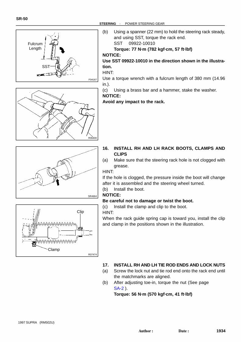
(b) Using a spanner (22 mm) to hold the steering rack steady,and using SST, torque the rack end.SST 09922-10010Torque: 77 N·m (782 kgf·cm, 57 ft·lbf)
NOTICE:Use SST 09922-10010 in the direction shown in the illustra-tion.HINT:Use a torque wrench with a fulcrum length of 380 mm (14.96in.).(c) Using a brass bar and a hammer, stake the washer.NOTICE:Avoid any impact to the rack.
16. INSTALL RH AND LH RACK BOOTS, CLAMPS ANDCLIPS
(a) Make sure that the steering rack hole is not clogged withgrease.
HINT:If the hole is clogged, the pressure inside the boot will changeafter it is assembled and the steering wheel turned.(b) Install the boot.NOTICE:Be careful not to damage or twist the boot.(c) Install the clamp and clip to the boot.HINT:When the rack guide spring cap is toward you, install the clipand clamp in the positions shown in the illustration.
17. INSTALL RH AND LH TIE ROD ENDS AND LOCK NUTS(a) Screw the lock nut and tie rod end onto the rack end until
the matchmarks are aligned.(b) After adjusting toe-in, torque the nut (See page
SA-2 ).Torque: 56 N·m (570 kgf·cm, 41 ft·lbf)
R07105SST Fulcrum Length
-STEERING POWER STEERING GEARSR-51
1935Author: Date:
1997 SUPRA (RM502U)
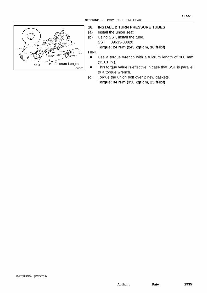
18. INSTALL 2 TURN PRESSURE TUBES(a) Install the union seat.(b) Using SST, install the tube.
SST 09633-00020Torque: 24 N·m (243 kgf·cm, 18 ft·lbf)
HINT: Use a torque wrench with a fulcrum length of 300 mm
(11.81 in.). This torque value is effective in case that SST is parallel
to a torque wrench.(c) Torque the union bolt over 2 new gaskets.
Torque: 34 N·m (350 kgf·cm, 25 ft·lbf)

SR14E-01
SR-52-STEERING POWER STEERING GEAR
1936Author: Date:
1997 SUPRA (RM502U)
INSTALLATION1. INSTALL PS GEAR ASSEMBLY(a) Temporarily install the 2 bolts and nuts.(b) After installing the rack housing bracket and grommet, torque the 2 bolts and nuts.
Torque: 75 N·m (770 kgf·cm, 55 ft·lbf)2. INSTALL RACK HOUSING BRACKET AND GROMMETTorque the 2 bolts and nuts.
Torque: 75 N·m (770 kgf·cm, 55 ft·lbf)3. CONNECT PPS SOLENOID CONNECTOR4. CONNECT PRESSURE FEED TUBETorque the union bolt over a new gasket.
Torque: 49 N·m (500 kgf·cm, 36 ft·lbf)5. CONNECT RETURN TUBETorque the union bolt over 2 new gaskets.
Torque: 49 N·m (500 kgf·cm, 36 ft·lbf)6. CONNECT RH AND LH TIE ROD ENDS (See page SA-17 )7. CONNECT INTERMEDIATE SHAFT (See page SR-21 )8. INSTALL FR SUSPENSION MEMBER PROTECTORTighten the 4 bolts.9. INSTALL ENGINE UNDER COVERInstall the 10 bolts.10. POSITION FRONT WHEELS FACING STRAIGHT AHEADHINT:Do it with the front of the vehicle jacked up.11. CENTER SPIRAL CABLE (See page SR-21 )12. INSTALL STEERING WHEEL(a) Align the matchmarks on the wheel and steering column main shaft.(b) Temporarily tighten the wheel set nut.(c) Connect the connector.13. BLEED POWER STEERING SYSTEM (See page SR-3 )14. CHECK STEERING WHEEL CENTER POINT15. TORQUE STEERING WHEEL SET NUT
Torque: 35 N·m (360 kgf·cm, 26 ft·lbf)16. INSTALL STEERING WHEEL PAD (See page SR-21 )17. CHECK FRONT WHEEL ALIGNMENT (See page SA-2 )

SR14F-01
F00595
PPS Solenoid Valve
PPS ECU
PPS ECUHeater to RegisterNo.5 Duct
Heater to RegisterNo.4 Duct
Instrument Panel Box
-STEERING PROGRESSIVE POWER STEERING (PPS)SR-53
1937Author: Date:
1997 SUPRA (RM502U)
PROGRESSIVE POWER STEERING (PPS)LOCATION

SR14G-01
F03098
Wire Harness Side:
SR4680
2 1
SR4681
2 1
SR-54-STEERING PROGRESSIVE POWER STEERING (PPS)
1938Author: Date:
1997 SUPRA (RM502U)
INSPECTION1. INSPECT ECU-IG FUSE (Instrument panel J/B)2. INSPECT PPS ECU CIRCUIT(a) Disconnect the PPS ECU connector.(b) Inspect the connector on wire harness side, as shown in
the illustration.
Tester connection Condition Specified condition
4 - Body ground Ignition switch ON Battery positive voltage
6 - Body ground Ignition switch ON Continuity
*5 - 6
Ignition switch ON.
Spin the rear wheel on one side with jacking or
lifting UP.
0 → 5 or more → 0
If the circuit is not as specified, check and replace the wire har-ness.*If the circuit is not as specified, inspect the speed sensor.
3. INSPECT PPS SOLENOID VALVE(a) Disconnect the PPS solenoid connector.(b) Measure the resistance between the terminals of the so-
lenoid 1 and 2.Resistance: 6 - 11 Ω
If it is not as specified, replace the pressure control valve withthe solenoid valve.
(c) Check the PPS solenoid operation.(1) Connect the battery positive terminal to the sole-
noid terminal 1.(2) Connect the battery negative terminal to the sole-
noid terminal 2.(3) Check that the solenoid makes a ”clicks” sound.
If it is faulty, replace the pressure control valve with the solenoidvalve.NOTICE: Do not apply voltage for more than 30 seconds to
avoid burning out the solenoid. If repeating this step, wait until the solenoid cools
down enough that it can be touched by hand.(d) Connect the PPS solenoid connector.

F03098
Wire Harness Side:
R07587
6 2
R07587
37 mph (60 km/h)
6 2
-STEERING PROGRESSIVE POWER STEERING (PPS)SR-55
1939Author: Date:
1997 SUPRA (RM502U)
(e) Inspect the PPS solenoid valve circuit.(1) Disconnect the PPS ECU connector.(2) Check continuity between the terminals of the con-
nector on wire harness side, as shown in the illustra-tion.
Tester connection Specified condition
1 - 6 No continuity
2 - 6 No continuity
If it is not as specified, repair or replace wire harness or connec-tor.
(3) Connect the PPS ECU connector.
4. INSPECT PPS ECU(a) Jack up the vehicle and support it on stands.(b) Start the engine.(c) Measure the voltage of ECU.
(1) Using a voltmeter, measure the voltage betweenECU terminals 2 and 6 while the engine is idling.
Standard voltage: 0.15 - 0.20 V
(2) Place the transmission in gear and while running atabout 62 mph (100 km/h), measure the voltage be-tween ECU terminals 2 and 6.
Standard voltage: 2JZ-GE: 0.06 - 0.17 v2JZ-GTE: 0.07 - 0.17 v
If no voltage, try another ECU for SUPRA.(d) Lower the vehicle.