Embed Size (px)
Citation preview

Symantec Corporation
NetBackup 5000
Release 1.3
Troubleshooting
Issue 02
Date 2011-03-21

Symantec Corporation
Symantec provides customers with comprehensive technical support and service. For any assistance, please contact our local office or company headquarters.
Symantec Corporation
Address: 350 Ellis St, Mountain View CA 94043
Website: http://www.symantec.com
Copyright © Symantec Corporation.2010-2011. All rights reserved.
No part of this document may be reproduced or transmitted in any form or by any means without prior written consent of Symantec Corporation.
Trademarks and Permissions
and other Symantec trademarks are trademarks of Symantec Corporation.
All other trademarks and trade names mentioned in this document are the property of their respective holders.
Notice
The purchased products, services and features are stipulated by the contract made between Symantec
and the customer. All or part of the products, services and features described in this document may not be
within the purchase scope or the usage scope. Unless otherwise specified in the contract, all statements,
information, and recommendations in this document are provided "AS IS" without warranties, guarantees
or representations of any kind, either express or implied.
The information in this document is subject to change without notice. Every effort has been made in the
preparation of this document to ensure accuracy of the contents, but all statements, information,
andrecommendations in this document do not constitute the warranty of any kind, express or implied.

NetBackup 5000
Troubleshooting Contents
Issue 02 (2011-03-21) Symantec Corporation i
Contents
About This Document .......................................................................................................... A.1.1-1
1 Safety Precautions ...................................................................................................................... 1-1
1.1 Warning and Safety Identifiers ...................................................................................................................... 1-1
1.2 ESD Prevention ............................................................................................................................................. 1-2
1.3 Short-Circuit Protection ................................................................................................................................ 1-3
1.4 Electrical Safety ............................................................................................................................................ 1-3
2 Troubleshooting Preparation ................................................................................................... 2-1
2.1 List of Tools and Instruments ........................................................................................................................ 2-1
2.2 Requirements on the Maintenance Personnel ................................................................................................ 2-2
2.3 Preparing Spare Parts .................................................................................................................................... 2-3
3 Principles and Methods of Troubleshooting ........................................................................ 3-1
3.1 Basic Principles ............................................................................................................................................. 3-1
3.2 Common Methods ......................................................................................................................................... 3-1
3.2.1 Alarm Analyzing Method ..................................................................................................................... 3-2
3.2.2 Replacement Method ........................................................................................................................... 3-2
4 Troubleshooting ......................................................................................................................... 4-1
4.1 Troubleshooting Process ............................................................................................................................... 4-1
4.2 Fault Classification ........................................................................................................................................ 4-5
4.3 Troubleshooting of Common Faults .............................................................................................................. 4-5
4.3.1 Power-on Failure .................................................................................................................................. 4-6
4.3.2 The memory size detected is less than the installed size .................................................................... 4-10
4.3.3 The disks detected is less than the installed ....................................................................................... 4-13
4.3.4 Fan Running/Alarm Indicator On and Red ........................................................................................ 4-16
4.3.5 Power Supply Alarm .......................................................................................................................... 4-20
4.3.6 Powered off Abnormally .................................................................................................................... 4-22
4.3.7 System Alarm Indicator On ................................................................................................................ 4-24
4.3.8 Operating System Boot Failure .......................................................................................................... 4-27
4.3.9 PD Manager Interface Slow to Respond ............................................................................................ 4-29
4.3.10 Second Node Auto-Discovery Failure.............................................................................................. 4-30
4.3.11 PD Manager Login Failure ................................................................................................................. 4-1
4.3.12 Failure of MSM Automatic Refreshing .............................................................................................. 4-1

Contents
NetBackup 5000
Troubleshooting
ii Symantec Corporation Issue 02 (2011-03-21)
4.3.13 Network Reconfiguration Failure ...................................................................................................... 4-2
4.3.14 PD Services Failure to Start Normally ............................................................................................... 4-5
4.3.15 No Response of the MSM Management Interface ............................................................................. 4-7
4.3.16 No CPU and Disk Information Displayed on ISM Interface ............................................................. 4-8
5 Replacing Parts ........................................................................................................................... 5-1
5.1 Preparations for Replacing Parts ................................................................................................................... 5-2
5.2 Precautions for Replacing Parts .................................................................................................................... 5-2
5.3 Replacing a Disk Module .............................................................................................................................. 5-3
5.4 Replacing a Fan Module ............................................................................................................................... 5-8
5.5 Replacing a Power Supply .......................................................................................................................... 5-14
5.6 Replacing a Mini SAS Cable ...................................................................................................................... 5-16
5.7 Replacing a RAID Card .............................................................................................................................. 5-22
5.8 Replacing a RAID Card battery .................................................................................................................. 5-27
5.9 Replacing a NIC .......................................................................................................................................... 5-29
5.10 Replacing a DIMM.................................................................................................................................... 5-32
5.11 Replacing a CPU ....................................................................................................................................... 5-36
5.12 Replacing chassis ...................................................................................................................................... 5-40
6 Case Collections ......................................................................................................................... 6-1
6.1 No Self-Check Interface of the RAID Card Is Displayed During the Self-Check Process of the NetBackup
5000 ..................................................................................................................................................................... 6-2
6.2 After the Device Is Powered On and MegaRAID Is Prompted, “F/W Initializing device 0%” Is
Displayed During the Self-Check Process of the RAID Card ............................................................................. 6-3
6.3 When the NetBackup 5000 Starts, the RAID Card Cannot Pass the Self-Check .......................................... 6-4
6.4 Slot Numbers of Hard Disks Are in Disorder ................................................................................................ 6-5
6.5 After the NetBackup 5000 Starts, “Invalid SAS topology detected” Is Displayed and the System Cannot
Be Accessed ........................................................................................................................................................ 6-6
6.6 The Service Network of the NetBackup 5000 Is Blocked ............................................................................. 6-7
6.7 The ISM Interface Cannot Be Logged In To ................................................................................................. 6-8
6.8 The IPMITOOL Fails to Connect the IPMI Port ........................................................................................... 6-8
6.9 After a Faulty Disk Is Replaced, the Alarm Persists .................................................................................... 6-10
6.10 The System Cannot Start and the Screen Is Black .................................................................................... 6-11
6.11 The Online Status Indicator of the Hard Disk Is Off ................................................................................. 6-13
6.12 Running the Install.VRTSat.sh Script Fails ............................................................................................... 6-13
6.13 WebBIOS Interface Can Not Enter ........................................................................................................... 6-15
7 Related Operations ...................................................................................................................... 7-1
7.1 Logging In to the System Monitoring Interface ............................................................................................ 7-1
7.2 Collecting Log Information ........................................................................................................................... 7-3
8 Monitoring from System Interface ......................................................................................... 8-1
8.1 Checking the CPU State ................................................................................................................................ 8-1
8.2 Viewing the Disk State .................................................................................................................................. 8-2
8.3 Check the RAID Group State ........................................................................................................................ 8-3

NetBackup 5000
Troubleshooting Contents
Issue 02 (2011-03-21) Symantec Corporation iii
8.4 Checking the Fan State .................................................................................................................................. 8-5
8.5 Checking the Power Supply State ................................................................................................................. 8-6
8.6 Viewing Hardware Alarms ............................................................................................................................ 8-7
9 Monitoring from MSM ............................................................................................................. 9-1
9.1 Monitoring MSM Events .............................................................................................................................. 9-1
9.2 Monitoring Controller ................................................................................................................................... 9-2
9.3 Monitoring Drives ......................................................................................................................................... 9-3
9.4 Monitoring Virtual Drives ............................................................................................................................. 9-4
9.5 Monitoring Battery Backup Units ................................................................................................................. 9-5
9.6 Monitoring Rebuilds and Other Processes .................................................................................................... 9-6
9.7 Events and Messages ..................................................................................................................................... 9-7
10 Monitoring from ISM ............................................................................................................ 10-1
10.1 Main Interface ........................................................................................................................................... 10-1
10.2 Device Info ................................................................................................................................................ 10-2
10.3 Sensor List ................................................................................................................................................. 10-3
10.4 Alarm Statistics ......................................................................................................................................... 10-4
10.5 Viewing Alarms ......................................................................................................................................... 10-5
10.6 Alarms type ............................................................................................................................................... 10-6
A How to Obtain Help .................................................................................................................. A-1
A.1 Preparations for Contacting Huawei Symantec ........................................................................................... A-1
A.1.1 Collecting Troubleshooting Information ............................................................................................ A-1
A.1.2 Making Debugging Preparations ........................................................................................................ A-2
A.2 How to Use the Document .......................................................................................................................... A-2
A.3 How to Obtain Help from Websites............................................................................................................. A-2
A.4 How to Contact Huawei Symantec .............................................................................................................. A-2
B Acronyms and Abbreviations ................................................................................................... 10-1


NetBackup 5000
Troubleshooting Figures
Issue 02 (2011-03-21) Symantec Corporation v
Figures
Figure 4-1 Troubleshooting process .................................................................................................................... 4-2
Figure 4-2 Location of the system power indicator ............................................................................................. 4-7
Figure 4-3 Location of the power running/alarm indicator ................................................................................. 4-8
Figure 4-4 Flow chart of troubleshooting power-on failure ................................................................................ 4-9
Figure 4-5 Flow chart of handling the fault that only part of the memory is detected ...................................... 4-11
Figure 4-6 Location of the memory sockets ...................................................................................................... 4-12
Figure 4-7 Location of the disk online indicator ............................................................................................... 4-13
Figure 4-8 Flow chart of handling the failure of finding all disks on the NetBackup 5000 monitoring interface 4-
14
Figure 4-9 Flow chart of handling the fault that the disk online indicator is on and red ................................... 4-15
Figure 4-10 Flow chart of handling the fault that the fan running/alarm indicator is on and red ...................... 4-17
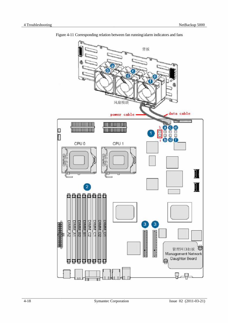
Figure 4-11 Corresponding relation between fan running/alarm indicators and fans ........................................ 4-18
Figure 4-12 Normal state of the fan connector .................................................................................................. 4-19
Figure 4-13 Flow chart of handling the power supply alarm ............................................................................ 4-21
Figure 4-14 Flow chart of handling improper power-off during the running of the device .............................. 4-23
Figure 4-15 Flow chart of handling the failure when the system alarm indicator is on .................................... 4-25
Figure 4-16 Installing the rear cover of the chassis ........................................................................................... 4-27
Figure 4-17 Flow chart of handling the operating system boot failure ............................................................. 4-28
Figure 4-18 Setting the boot devices in BIOS ................................................................................................... 4-29
Figure 4-19 Flow chart of handling the fault that the PD Manager is slow to respond ..................................... 4-30
Figure 4-20 Flow chart of handling the second node auto-discovery failure .................................................... 4-31
Figure 4-21 Error message .................................................................................................................................. 4-1
Figure 4-22 Flow chart of handling the fault that the PD Manager cannot be logged in to ................................ 4-2
Figure 4-23 Flow chart of handling the fault that the MSM cannot refresh automatically ................................. 4-1
Figure 4-24 Network reconfiguration .................................................................................................................. 4-3
Figure 4-25 Network reconfiguration failure ...................................................................................................... 4-3
Figure 4-26 Flow chart of troubleshooting network reconfiguration failure ....................................................... 4-4

Figures
NetBackup 5000
Troubleshooting
vi Symantec Corporation Issue 02 (2011-03-21)
Figure 4-27 Flow chart of handling the fault that PD services fail to start normally .......................................... 4-6
Figure 4-28 Flow chart of handling the fault that the MSM management interface does not respond ............... 4-7
Figure 4-29 ISM interface failing to display CPU and disk information ............................................................ 4-8
Figure 4-30 Flow chart of handling the ISM CPU and disk information display failure .................................... 4-9
Figure 4-31 Configuring the IPMI network ...................................................................................................... 4-10
Figure 4-32 Configuring System interface ........................................................................................................ 4-11
Figure 4-33 Displaying the CPU and disk information ..................................................................................... 4-11
Figure 5-1 Seagate logo....................................................................................................................................... 5-4
Figure 5-2 Wearing the ESD-preventive wrist strap with a plug ......................................................................... 5-4
Figure 5-3 Wearing the ESD-preventive wrist strap with a metal clip ................................................................ 5-5
Figure 5-4 Removing a disk module ................................................................................................................... 5-6
Figure 5-5 Installing a disk module ..................................................................................................................... 5-7
Figure 5-6 Getting the property of copyback function ........................................................................................ 5-8
Figure 5-7 Setting Replace Physical Drive ......................................................................................................... 5-8
Figure 5-8 Removing the NetBackup 5000 from the cabinet ............................................................................ 5-10
Figure 5-9 Removing the middle cover from the chassis .................................................................................. 5-11
Figure 5-10 Removing a fan module ................................................................................................................. 5-11
Figure 5-11 Installing a fan module .................................................................................................................. 5-12
Figure 5-12 Installing the middle cover of the chassis ...................................................................................... 5-12
Figure 5-13 Installing the NetBackup 5000 into the cabinet ............................................................................. 5-13
Figure 5-14 Removing a power supply ............................................................................................................. 5-15
Figure 5-15 Installing a power supply ............................................................................................................... 5-16
Figure 5-16 Removing the rear cover of the chassis ......................................................................................... 5-18
Figure 5-17 Removing a Mini SAS cable ......................................................................................................... 5-19
Figure 5-18 Installing a RAID card ................................................................................................................... 5-20
Figure 5-19 Installing the rear cover of the chassis ........................................................................................... 5-21
Figure 5-20 RAID card detect all disks ............................................................................................................. 5-22
Figure 5-21 Removing a RAID card ................................................................................................................. 5-24
Figure 5-22 Removing and installing the battery module of the RAID card .................................................... 5-25
Figure 5-23 Installing a RAID card ................................................................................................................... 5-26
Figure 5-24 RAID card detect the RAID configuration .................................................................................... 5-27
Figure 5-25 RAID card detect the VD configuration ........................................................................................ 5-27
Figure 5-26 Removing a NIC ............................................................................................................................ 5-30

NetBackup 5000
Troubleshooting Figures
Issue 02 (2011-03-21) Symantec Corporation vii
Figure 5-27 Installing a NIC ............................................................................................................................. 5-31
Figure 5-28 Removing a wind cover ................................................................................................................. 5-33
Figure 5-29 Removing a DIMM ....................................................................................................................... 5-34
Figure 5-30 Loosening a DIMM fixing clip ...................................................................................................... 5-34
Figure 5-31 Installing a DIMM ......................................................................................................................... 5-35
Figure 5-32 Installing a wind cover .................................................................................................................. 5-35
Figure 5-33 System post the memory size ........................................................................................................ 5-36
Figure 5-34 Removing a CPU cooling fin ......................................................................................................... 5-38
Figure 5-35 Installing a CPU cooling fin .......................................................................................................... 5-39
Figure 5-36 System post the CPU message ....................................................................................................... 5-39
Figure 5-37 IPMI IP address displayed on the system self-check Page ............................................................ 5-41
Figure 5-38 ipmitool directory ............................................................................. Error! Bookmark not defined.
Figure 5-39 Pressing Del during the system self-check ........................................ Error! Bookmark not defined.
Figure 5-40 Setting the IP address and subnet mask ............................................. Error! Bookmark not defined.
Figure 5-41 Choosing Send to BMC .................................................................... Error! Bookmark not defined.
Figure 5-42 Choosing Save Changes and Exit. ................................................... Error! Bookmark not defined.
Figure 5-43 Running the upgrade.EXE command .............................................. Error! Bookmark not defined.
Figure 5-44 Options under Welcome to BMC SOL ............................................ Error! Bookmark not defined.
Figure 5-45 Typing the password .......................................................................... Error! Bookmark not defined.
Figure 5-46 Modifying the zone setting ................................................................ Error! Bookmark not defined.
Figure 5-47 Checking the zone setting .................................................................. Error! Bookmark not defined.
Figure 5-48 YaST control center ....................................................................................................................... 5-43
Figure 5-49 Selecting Date and Time ................................................................................................................ 5-44
Figure 5-50 Setting the time zone ..................................................................................................................... 5-44
Figure 5-51 Setting the date and time ............................................................................................................... 5-45
Figure 5-52 Confirming the changes ................................................................................................................. 5-45
Figure 5-53 Config network card ...................................................................................................................... 5-46
Figure 5-54 Select network card ....................................................................................................................... 5-46
Figure 5-55 Edit network card IP address ......................................................................................................... 5-47
Figure 6-1 Checking the mini SAS cables .......................................................................................................... 6-5
Figure 6-2 Debugging serial port interface of the expansion board .................................................................. 6-10
Figure 6-3 Debugging serial port interface of the expansion board .................................................................. 6-11
Figure 6-4 80 port.............................................................................................................................................. 6-12

Figures
NetBackup 5000
Troubleshooting
viii Symantec Corporation Issue 02 (2011-03-21)
Figure 6-5 Failing to run the Install.VRTSat.sh script ...................................................................................... 6-14
Figure 6-6 Press Ctrl + H to enter WebBIOS interface ..................................................................................... 6-15
Figure 6-7 Press Del to enter BIOS interface .................................................................................................... 6-16
Figure 6-8 Choose Boot Settings Configuration ............................................................................................... 6-16
Figure 6-9 Choose Interrup 19 Capture ............................................................................................................. 6-17
Figure 6-10 Press Del to enter BIOS interface .................................................................................................. 6-17
Figure 7-1 Login Interface .................................................................................................................................. 7-2
Figure 7-2 Main interface of the NetBackup 5000 .............................................................................................. 7-2
Figure 7-3 System monitoring interface .............................................................................................................. 7-3
Figure 8-1 View CPU staus ................................................................................................................................. 8-2
Figure 8-2 View disk staus .................................................................................................................................. 8-3
Figure 8-3 View RAID staus ............................................................................................................................... 8-4
Figure 8-4 View FAN staus ................................................................................................................................. 8-5
Figure 8-5 View Power Supply staus .................................................................................................................. 8-6
Figure 8-6 View Hardware Alarms...................................................................................................................... 8-7
Figure 9-1 Event Information Window ............................................................................................................... 9-2
Figure 9-2 Shows the Controller Information ..................................................................................................... 9-3
Figure 9-3 Drive Information .............................................................................................................................. 9-4
Figure 9-4 Virtual Drive Properties ..................................................................................................................... 9-5
Figure 9-5 Battery Backup Unit Information ...................................................................................................... 9-6
Figure 9-6 Show Progress Window ..................................................................................................................... 9-7
Figure 10-1 Main interface of the ISM ............................................................................................................. 10-2
Figure 10-2 Querying the main information about the device .......................................................................... 10-3
Figure 10-3 Viewing the sensor information ..................................................................................................... 10-3
Figure 10-4 Alarm statistics .............................................................................................................................. 10-5
Figure 10-5 Viewing alarms .............................................................................................................................. 10-6

NetBackup 5000
Troubleshooting Tables
Issue 02 (2011-03-21) Symantec Corporation ix
Tables
Table 1-1 Identifiers and meanings ..................................................................................................................... 1-2
Table 2-1 List of tools and instruments for troubleshooting ................................................................................ 2-1
Table 4-1 Information about the status of indicators ........................................................................................... 4-2
Table 4-2 Memory installation checklist ........................................................................................................... 4-12
Table 4-3 Alarm information ............................................................................................................................. 4-24
Table 6-1 Corresponding relationship between the fault code and the fault cause ............................................ 6-12
Table 8-1 Description of parameters related to the CPU state ............................................................................. 8-2
Table 8-2 Description of parameters related to the disk state .............................................................................. 8-3
Table 8-3 Description of parameters related to the RAID group state ................................................................ 8-4
Table 8-4 Description of parameters related to the fan state ............................................................................... 8-5
Table 8-5 Description of parameters related to the power supply state ............................................................... 8-6
Table 8-6 Description of alarm parameters ......................................................................................................... 8-7
Table 8-7 Alarm information ............................................................................................................................... 8-8
Table 9-1 MSM Event Severity Levels ............................................................................................................... 9-2
Table 9-2 MSM Event Messages ......................................................................................................................... 9-7
Table 10-1 ISM Event Messages ....................................................................................................................... 10-6


NetBackup 5000
Issue 02 (2011-03-21) Symantec Corporation A.1.1-1
About This Document
Purpose This document describes the troubleshooting process and methods of the NetBackup 5000.
Related Versions The following table lists the product versions related to this document.
Product Name Version
NetBackup 5000 Release 1.3
Intended Audience This document is intended for:
Technical support engineers
Maintenance engineers
Organization This document is organized as follows.
Chapter Description
1 Safty Precautions Describes the safety precautions to be followed during
troubleshooting.
2 Troubleshooting Preparation Describes preparations before troubleshooting, such as
preparing spare parts and the list of tools and instruments,
and raising requirements on maintenance personnel.
3 Principles and Methods of
Locating Faults
Describes principles and common methods of locating
faults.
4 Troubleshooting Describes the troubleshooting process, fault classification,
and handling of common faults.

NetBackup 5000
A.1.1-2 Symantec Corporation Issue 02 (2011-03-21)
Chapter Description
5 Replacing Parts Describes preparations, precautions, and methods of
replacing components of the NetBackup 5000.
6 Related Operations Describes the related operations during the
troubleshooting process.
A How to obtain help Describes how to obtain the help from Huawei Symantec.
B Acronyms and abbreviations Describes the acronyms and abbreviations referred to in
this document.
Conventions
Symbol Conventions
The symbols that may be found in this document are defined as follows.
Symbol Description
Indicates a hazard with a high level of risk, which if not
avoided, will result in death or serious injury.
Indicates a hazard with a medium or low level of risk,
which if not avoided, could result in minor or moderate
injury.
Indicates a potentially hazardous situation, which if not
avoided, could result in equipment damage, data loss, and
performance degradation, or unexpected results.
Indicates a tip that may help you handle a fault or save
time.
Provides additional information to emphasize or
supplement important points of the main text.
General Conventions
The general conventions that may be found in this document are defined as follows.
Convention Description
Times New Roman Normal paragraphs are in Times New Roman.
Boldface Names of files, directories, folders, and users are in
boldface. For example, log in as user root.
Italic Book titles are in italics.

NetBackup 5000
Issue 02 (2011-03-21) Symantec Corporation A.1.1-3
Convention Description
Courier New Examples of information displayed on the screen are in
Courier New.
Command Conventions
The command conventions that may be found in this document are defined as follows.
Convention Description
Boldface The keywords of a command line are in boldface.
Italic Command arguments are in italics.
[ ] Items (keywords or arguments) in brackets [ ] are optional.
{ x | y | ... } Optional items are grouped in braces and separated by vertical
bars. One item is selected.
[ x | y | ... ] Optional items are grouped in braces and separated by vertical
bars. One item is selected or no item is selected.
{ x | y | ... }* Optional items are grouped in braces and separated by vertical
bars. A minimum of one item or a maximum of all items can be
selected.
[ x | y | ... ]* Optional items are grouped in brackets and separated by
vertical bars. Several items or no item can be selected.
GUI Conventions
The GUI conventions that may be found in this document are defined as follows.
Convention Description
Boldface Buttons, menus, parameters, tabs, windows, and dialog titles
are in boldface. For example, click OK.
> Multiple levels of a menu are in boldface and separated by the
">" signs. For example, choose File > Create > Folder.
Keyboard Conventions
The keyboard operations that may be found in this document are defined as follows.
Convention Description
Key Press the key. For example, press Enter and press Tab.

NetBackup 5000
A.1.1-4 Symantec Corporation Issue 02 (2011-03-21)
Convention Description
Key 1+Key 2 Press the keys concurrently. For example, pressing
Ctrl+Alt+A means the three keys should be pressed
concurrently.
Key 1, Key 2 Press the keys in turn. For example, pressing Alt, A means the
two keys should be pressed in turn.
Mouse Operations
The mouse operations that may be found in this document are defined as follows.
Action Description
Click Select and release the primary mouse button without moving
the pointer.
Double-click Press the primary mouse button twice continuously and quickly
without moving the pointer.
Drag Press and hold the primary mouse button and move the pointer
to a certain position.
Update History Updates between document issues are cumulative. Therefore, the latest document issue
contains all updates made in previous issues.
Updates in Issue 02 (2011-03-21)
The second commercial release. The updated contents are as follows.
Add all spare disks produced by Seagate only.
Add zone setting and checking procedure after replacing chassis.
Add the procedure of synchronizing BIOS time and BMC time.
Revise some link error.
Updates in Issue 01 (2010-04-02)
Initial commercial release.

NetBackup 5000 1 Safety Precautions
Issue 02 (2011-03-21) Symantec Corporation 1-1
1 Safety Precautions
About This Chapter This chapter describes the safety precautions to be followed during troubleshooting.
1.1 Warning and Safety Identifiers
When installing and maintaining the equipment, observe the precautions indicated by the
warning and safety identifiers to prevent personal injury or equipment damage.
1.2 ESD Prevention
When installing and maintaining the equipment, follow the safety precautions of ESD
prevention to ensure the safety of the human body and the device.
1.3 Short-Circuit Protection
When installing or maintaining the device, use and put the tools according to the regulations
to avoid short circuit caused by metallic tools.
1.4 Electrical Safety
When installing and maintaining the equipment, follow the electrical safety precautions to
avoid device damage or human injury.
1.1 Warning and Safety Identifiers When installing and maintaining the equipment, observe the precautions indicated by the
warning and safety identifiers to prevent personal injury or equipment damage.
Table 1-1 lists the warning and safety identifiers on the device and the meanings of the
identifiers.

1 Safety Precautions NetBackup 5000
1-2 Symantec Corporation Issue 02 (2011-03-21)
Table 1-1 Identifiers and meanings
Symbol Description
ESD prevention identifier
When performing operations at this area, you need to
take strict measures, such as wearing electrostatic
discharge (ESD) preventive gloves or an ESD-
preventive wrist strap, to avoid electrostatic injuries.
Subrack grounding identifier
Indicating the grounding position.
Warning identifier for removing or inserting the system
disks
Prompting that you cannot remove or insert the system
disks at will.
1.2 ESD Prevention When installing and maintaining the equipment, follow the safety precautions of ESD
prevention to ensure the safety of the human body and the device.
indicates an electrostatic sensitive area. When performing operations at this area,
you need to take strict measures, such as wearing an ESD-preventive wrist strap, ESD-
preventive gloves, and ESD-preventive clothes, to avoid personal injuries or device damages
caused by the static electricity.
To protect the devices, pay attention to the following during operations:
Do not touch the exposed device modules with bare hands because the static electricity
of the human body may damage the electrostatic sensitive elements on the circuit boards.
The electronic circuit is prone to ESD damages. When handling disks, especially raw
disks, you need to wear an ESD preventive-wrist strap, ESD-preventive gloves, and
ESD-preventive clothes. Besides, touch only the disk edges.
The ESD-preventive wrist strap can only prevent the devices from being damaged by the
static electricity of the human body. To prevent the devices from being damaged by the
static electricity of the clothes, you need to wear the ESD-preventive clothes.
To avoid personal injuries or device damages caused by the static electricity, you need to
wear ESD-preventive gloves or an ESD-preventive wrist strap before installation or
replacement.
When carrying or moving parts, a dedicated ESD-preventive bag is required.

NetBackup 5000 1 Safety Precautions
Issue 02 (2011-03-21) Symantec Corporation 1-1
1.3 Short-Circuit Protection When installing or maintaining the device, use and put the tools according to the regulations
to avoid short circuit caused by metallic tools.
Do not drop screws into the subrack or the device; otherwise, short circuit may occur.
1.4 Electrical Safety When installing and maintaining the equipment, follow the electrical safety precautions to
avoid device damage or human injury.
Power-on and Power-off
Before checking the installation and cable connection, ensure that the entire storage system is
powered off. Otherwise, if there is improper connection, your body or the device may be
damaged during the check.
During power-on, do not insert or remove the cable or field replaceable unit (FRU).
Otherwise, data may be lost.
After switching off the power supply, wait at least one minute before switching on the
power supply again.
Do not switch off or on the power supply before disks stop running. Otherwise, disks
may be damaged and data may be lost.
Troubleshooting
Do not touch the plugs of power cables and communication cables, for the electricity inside
the power cables and communication cables could result in electrical shock.

1 Safety Precautions NetBackup 5000
1-2 Symantec Corporation Issue 02 (2011-03-21)
When operating a device in the ESD-sensitive area, you must take ESD-preventive measures,
such as wearing an ESD-preventive wrist strap, ESD-preventive clothes, and ESD-preventive
gloves, to avoid device damage or human injuries caused by the static electricity.
Pay attention to the following items during troubleshooting:
Do not troubleshoot in the case of lightning.
Check that the power cables are intact and effective grounding measures are taken.
Keep the troubleshooting area clean and dry.

NetBackup 5000 2 Troubleshooting Preparation
Issue 02 (2011-03-21) Symantec Corporation 2-1
2 Troubleshooting Preparation
About This Chapter
This chapter describes preparations before troubleshooting, such as preparing the spare parts
and list of tools and instruments, and raising requirements on maintenance personnel.
2.1 List of Tools and Instruments
This section describes the list of tools and instruments.
2.2 Requirements on the Maintenance Personnel
This section describes the professional skills and knowledge that the maintenance personnel
should master.
2.3 Preparing Spare Parts
This section describes the spare parts that the field engineers should prepare.
2.1 List of Tools and Instruments This section describes the list of tools and instruments.
Table 2-1 lists the tools and instruments for troubleshooting.
Table 2-1 List of tools and instruments for troubleshooting
Tool Name Use
Optical power meter Used for measuring the optical power.
Network cable Used for replacing the faulty network cable.
Line tester Used for measuring the connection of the
network cables on the Ethernet.
Multimeter Used for testing the electrical parameters.
ESD-preventive wrist strap Avoiding damaging the ESSDs by the static
electricity of the body.

2 Troubleshooting Preparation NetBackup 5000
2-2 Symantec Corporation Issue 02 (2011-03-21)
Tool Name Use
ESD-preventive bag Protecting the components from
electrostatic discharge.
ESD-preventive clothes Avoiding damaging the ESSDs by the static
electricity of the body.
Philips screwdriver Used for dismantling screws on the device.
Tag Used for marking devices or cables.
2.2 Requirements on the Maintenance Personnel This section describes the professional skills and knowledge that the maintenance personnel
should master.
Professional Skills
Familiar with storage technologies, such as RAID, DAS, NAS, and SAN
Familiar with the iSCSI protocol and SAS protocol
Familiar with the Ethernet technology
Familiar with common operating systems
Familiar with common maintenance methods of the devices
Basic Operations
Able to operate various types of application servers
Able to operate data transmission devices that are related to the storage business
For example: Ethernet switches, FC switches, and routers
Common Test Meters
Optical power meter
Line tester
Multimeter
Storage Networking Information
Familiar with common storage networking modes
Familiar with the networking of the maintenance office
Familiar with the running status of the devices of the maintenance office
Collecting and Keeping the Field Data
Collects and keeps alarm information of the device
Collects and keeps event information of the device
Collects and keeps the operation log of the device
NetBackup 5000 2 Troubleshooting Preparation
Issue 02 (2011-03-21) Symantec Corporation 2-3
Collects and keeps performance data of the device
Collects and keeps configuration data of the device
Collects and keeps running application data of the device
2.3 Preparing Spare Parts
This section describes the spare parts that the field engineers should prepare.
Before knowing the field situation, the engineers should carry spare parts to the site. The
following spare parts can be carried:
Disk module
Fan module
Power supply
RAID card
NIC
DIMM
CPU
Chassis


NetBackup 5000 3 Principles and Methods of Troubleshooting
Issue 02 (2011-03-21) Symantec Corporation 3-1
3 Principles and Methods of Troubleshooting
About This Chapter
This chapter describes principles and common methods of troubleshooting.
3.1 Basic Principles
This section describes the basic principles of troubleshooting.
3.2 Common Methods
This section describes common methods of troubleshooting.
3.1 Basic Principles
This section describes the basic principles of troubleshooting.
When troubleshooting, observe the following principles:
Analyze the external factors and then the internal factors.
When troubleshooting, exclude the problem of the external devices first, such as the fault
of cables or devices and power interruption.
Analyze the alarms with common features and then alarms with exceptional features.
When analyzing an alarm, analyze whether the fault is common or exceptional first to
determine the impact range. Then analyze whether the fault occurs on one module or
multiple modules.
3.2 Common Methods
This section describes common methods of troubleshooting.
3.2.1 Alarm Analyzing Method
This section describes the alarm analyzing method.
3.2.2 Replacement Method

3 Principles and Methods of Troubleshooting NetBackup 5000
3-2 Symantec Corporation Issue 02 (2011-03-21)
This section describes how to locate faults through the replacement method.
3.2.1 Alarm Analyzing Method
This section describes the alarm analyzing method.
It is Symantec that supplements the details of the software alarm analyzing method.
Overview
When the system is faulty, a great amount of alarms are generated. By querying the alarms
and analyzing the performance data, you can basically determine the type and location of the
fault.
Application Scenario
If alarms can be normally collected, the alarm analyzing method applies to locating any fault.
Summary
By the alarm analyzing method, you can locate the fault or determine the cause for the fault,
or determine the cause for the fault by collaborating with other methods.
3.2.2 Replacement Method
This section describes how to troubleshooting through the replacement method.
Overview
The replacement method is to replace a part that may be faulty to reach the purpose of
locating and removing the fault. The part can be a cable, a power supply, or a fan module.
Application Scenario
The replacement method applies to troubleshoot the hardware. This method can quickly locate
faulty parts and has no special requirements on maintenance personnel. The limitation of the
replacement method lies in the preparation for the same spare parts; therefore, a full
preparation is required.
Summary
The replacement method is a practical method, because this method is advantageous to
locating the fault in detail and does not have high requirements on maintenance personnel.
To replace hardware, you need to make full preparations and observe the precautions. For details, see 5.1
Safety Precautions and 5.2 Precautions for Replacing Parts .

NetBackup 5000 4 Troubleshooting
Issue 02 (2011-03-21) Symantec Corporation 4-1
4 Troubleshooting
About This Chapter
This chapter describes the troubleshooting process, fault classification, and handling of
common faults.
4.1 Troubleshooting Process
This section describes the troubleshooting procedures, and how to acquire information and
obtain latest technical materials.
4.2 Fault Classification
This section describes how to classify the faults of the NetBackup 5000.
4.3 Troubleshooting of Common Faults
This section describes how to handle common faults.
4.1 Troubleshooting Process
This section describes the troubleshooting procedures, and how to acquire information and
obtain latest technical materials.
Flow Chart
Figure 4-1 shows the troubleshooting process.

4 Troubleshooting NetBackup 5000
4-2 Symantec Corporation Issue 02 (2011-03-21)
Figure 4-1 Troubleshooting process
Observing and Recording the Status of Indicators
Through the status of indicators, determine the faulty module.
Table 4-1 lists the information about the status of indicators.
Table 4-1 Information about the status of indicators
Indicator Location
Indicator Type Color Status Description
Chassis System power Green On The device is powered on.

NetBackup 5000 4 Troubleshooting
Issue 02 (2011-03-21) Symantec Corporation 4-3
Indicator Location
Indicator Type Color Status Description
indicator - Off
The device is powered
off.
System alarm
indicator
Red On
The device is out of
service, or an alarm is
generated on the device.
- Off The device is running
normally.
System location
indicator Orange On The device is located
a.
Disk module
Disk online indicator
Green On The disk is powered on
properly.
Red On
An alarm is generated on
the disk or the disk is
located a.
- Off The disk is powered on
improperly.
Disk read/write
indicator
Green Blinking Data is being transferred.
- Off No data is being
transferred.
power supply Power running/alarm
indicator
Green On The power supply works
properly.
Green Blinking
The power supply is
working normally and the
device is not switched on.
Orange On An alarm is generated on
the power supply.
- Off The power supply is
powered on improperly.
Mainboard Fan running/alarm
indicator
Green On The fan is working
normally.
Red On An alarm is generated on
the fan.
- Off The fan is powered on
improperly.
Rear panel
Link indicator of the
management
network port
Green On
The link to the
management network port
is normal.

4 Troubleshooting NetBackup 5000
4-4 Symantec Corporation Issue 02 (2011-03-21)
Indicator Location
Indicator Type Color Status Description
- Off
The link to the
management network port
is abnormal.
Active indicator of
the management
network port
Orange Blinking Data is being transferred.
- Off No data is being
transferred.
Link indicator of the
service network port
Green On
Data is transferred
between the NetBackup
5000 and the application
server (AS) at 1000
Mbit/s.
Orange On
Data is transferred
between the NetBackup
5000 and the AS at 100
Mbit/s.
- Off
Data is transferred
between the NetBackup
5000 and the AS at 10
Mbit/s or the link between
the NetBackup 5000 and
the AS is abnormal.
Active indicator of
the service network
port
Orange Blinking Data is being transferred.
- Off No data is being
transferred.
a: The location command is sent through the management system.
Logging In to the System Monitoring Interface
Log in to the system monitoring interface to view the alarm information, 7.1 “Logging In to
the System Monitoring Interface” shows the steps to log in to the system monitoring interface.
Locating the Fault
Fault location is the process of finding out the single cause for the fault among many possible
causes. By analyzing and comparing all possible causes, and then ruling out the impossible
factors, you can finally find out the cause for the fault.
For details on the methods of locating the fault, see 3.2 “Common Methods”.
Collecting Fault Information
When encountering some tricky faults, you can contact the Customer Service Center. Before
stating the faults to engineers, you are recommended to collect fault information for the
convenience of troubleshooting.

NetBackup 5000 4 Troubleshooting
Issue 02 (2011-03-21) Symantec Corporation 4-5
For details on requirements on collecting fault information, see To better solve the problem,
you need to collect troubleshooting information and make debugging preparations before
contacting Huawei Symantec.
A.1.1 Collecting Troubleshooting Information
You need to collect troubleshooting information before troubleshoot.
A.1.2 Making Debugging Preparations
When you contact Huawei Symantec for help, the technical support engineer of Huawei
Symantec might assist you to do certain operations to collect information about the fault or
rectify the fault directly.
Collecting Troubleshooting Information.
Obtaining Technical Support
You can obtain technical support by:
Reading documents. For details, see When you contact Huawei Symantec for help, the
technical support engineer of Huawei Symantec might assist you to do certain operations to
collect information about the fault or rectify the fault directly.
Before contacting Huawei Symantec for help, you need to prepare the boards, port modules,
screwdrivers, screws, cables for serial ports, network cables, and other required materials.
How to Use the Document.
Obtaining help from the website. For details, see How to Huawei Symantec provides guide
documents shipped with the device. The guide documents can be used to handle the common
problems occurring in daily maintenance or troubleshooting.
To better solve the problems, use the documents before you contact Huawei Symantec for
technical support.
How to Obtain Help from Websites.
Contacting Symantec. For details, see Huawei Symantec provides users with timely and
efficient technical support through the regional offices, secondary technical support system,
telephone technical support, remote technical support, and onsite technical support.
Contents of the Huawei Symantec technical support system are as follows:
Huawei Symantec headquarters technical support department
Regional office technical support center
Customer service center
Technical support website: http://www.Huaweisymantec.com
You can query how to contact the regional offices at http://www.Huaweisymantec.com.
How to Contact Huawei Symantec.
4.2 Fault Classification
This section describes how to classify the faults of the NetBackup 5000.
The faults of the NetBackup 5000 are classified into hardware faults and software faults.

4 Troubleshooting NetBackup 5000
4-6 Symantec Corporation Issue 02 (2011-03-21)
Hardware Faults
The common hardware faults include:
Faults during device installation
Faults during device running
The following measures can be taken to locate the hardware faults:
Check whether the device is properly installed.
Check whether the operating mode is properly set.
View device alarm message to determine the point of failure.
View the technical support documents delivered with the device.
Software Faults
The common software faults are provided by Symantec.
4.3 Troubleshooting of Common Faults
This section describes how to handle common faults.
4.3.1 Power-on Failure
This section describes how to troubleshoot power-on failure.
4.3.2 The memory size detected is less than the installed size
This section describes how to handle the fault that the memory size detected during BIOS
booting is less than the actual installed memory size.
4.3.3 The disks detected is less than the installed
This section describes how to handle the disks detected is less than the actual installed.
4.3.4 Fan Running/Alarm Indicator On and Red
This section describes how to handle the fault that the fan running/alarm indicator is on and
red.
4.3.5 Power Supply Alarm
This section describes how to handle the power supply alarm.
4.3.6 Powered off Abnormally
This section describes how to handle the fault that the NetBackup 5000 is powered off
abnormally.
4.3.7 System Alarm Indicator On
This section describes how to handle the fault that the system alarm indicator is on.
4.3.8 Operating System Boot Failure
This section describes how to handle the operating system boot failure.
4.3.9 PD Manager Interface Slow to Respond

NetBackup 5000 4 Troubleshooting
Issue 02 (2011-03-21) Symantec Corporation 4-7
This section describes how to handle the fault that the PD Manage interface is slow to respond.
4.3.10 Second Node Auto-Discovery Failure
This section describes how to handle the fault that the second NetBackup 5000 node cannot
be discovered automatically when you add that node to the existing NetBackup 5000.
4.3.11 PD Manager Login Failure
This section describes how to handle the fault that the PD Manager cannot be logged in to.
4.3.12 Failure of MSM Automatic Refreshing
This section describes how to handle the fault that the data cannot be refreshed after the
NetBackup 5000 is configured through the MSM client.
4.3.13 Network Reconfiguration Failure
This section describes how to handle the fault that the network configuration fails after the
initial configuration is cancelled.
4.3.14 PD Services Failure to Start Normally
This section describes how to handle the fault that PD services fail to start normally.
4.3.15 No Response of the MSM Management Interface
This section describes how to handle the fault that the MSM management interface does not
respond.
4.3.16 No CPU and Disk Information Displayed on ISM Interface
This section describes how to handle the fault that no CPU and disk information is displayed
on ISM management interface.
4.3.1 Power-on Failure
This section describes how to troubleshoot power-on failure.
Symptom
When you press the system power switch, the system power indicator is not on.
The system power indicator is located in the red square of Figure 4-2.

4 Troubleshooting NetBackup 5000
4-8 Symantec Corporation Issue 02 (2011-03-21)
Figure 4-2 Location of the system power indicator
Possible Causes
Possible causes for power-on failure are listed as follows:
1. The plug of the power supply is improperly inserted.
2. The power supply is not powered on.
When checking the power supply indicator status, the power running/alarm indicator is off, as
shown in Table 4-1. Figure 4-3 shows the location of the power running/alarm indicator.
Figure 4-3 Location of the power running/alarm indicator
1 power supply handle 2 power supply fan
3 Power running/alarm indicator 4 Power socket
5 power supply spring leaf

NetBackup 5000 4 Troubleshooting
Issue 02 (2011-03-21) Symantec Corporation 4-9
Fault Diagnosis
Figure 4-4 Flow chart of troubleshooting power-on failure
Procedure
Cause 1: The plug of the power supply is improperly inserted.
1. Reinsert the plug of the power supply.
2. Check the power running/alarm indicator.
− If the power running/alarm indicator blinks green, press the system power switch. If
the power running/alarm indicator is on, the fault is removed.
− If the power running/alarm indicator is orange, an alarm is generated on the power
supply. For details on handling alarms on the power supply, see 4.3.5 Power Supply
Alarm.
− If the power running/alarm indicator is still off, analyze the next cause.
Cause 2: The power supply is not powered on.
1. Switch on the external power socket of the NetBackup 5000, and power on the
NetBackup 5000.
2. Check the power running/alarm indicator.

4 Troubleshooting NetBackup 5000
4-10 Symantec Corporation Issue 02 (2011-03-21)
− If the power running/alarm indicator blinks green, press the system power switch. If
the power running/alarm indicator is on, the fault is removed.
− If the power running/alarm indicator is orange, an alarm is generated on the power
supply. For details on handling alarms on the power supply, see 4.3.5 Power Supply
Alarm.
− If the power running/alarm indicator is still off, contact the technical support
engineers.
3. If the measures above are noneffective, you should contact technical support engineers.
----End
Suggestion and Summary
If the types of the two CPUs installed on the mainboard are different, the device cannot be
powered on. Therefore, when you replace a CPU, you need to ensure that the type of the new
CPU and the other CPU is the same.
4.3.2 The memory size detected is less than the installed size
This section describes how to handle the fault that the memory size detected during BIOS
booting is less than the actual installed memory size.
Symptom
The memory size detected during BIOS booting is less than the installed memory size.
Possible Causes
Possible causes for detecting only part of the memory are listed as follows:
4. The DIMMs are located in incorrect slots.
5. The DIMMs are faulty.
6. The memory sockets are damaged.

NetBackup 5000 4 Troubleshooting
Issue 02 (2011-03-21) Symantec Corporation 4-11
Fault Diagnosis
Figure 4-5 Flow chart of handling the fault that only part of the memory is detected
Procedure
Cause 1: The DIMMs are installed into incorrect slots.
1. Before checking the DIMMs, power off the NetBackup 5000 and disconnect the
NetBackup 5000 from the power socket and external devices.
2. Check whether the DIMMs are in the correct slots as specified in Table 4-2. The memory
sockets in the main board of the NetBackup 5000 are located in the red square of Figure
4-6.

4 Troubleshooting NetBackup 5000
4-12 Symantec Corporation Issue 02 (2011-03-21)
Figure 4-6 Location of the memory sockets
Table 4-2 Memory installation checklist
Number of DIMMs
DIMM_A2
DIMM_A1
DIMM_B2
DIMM_B1
DIMM_C2
DIMM_C1
DIMM_D2
DIMM_D1
6 √ √ √ √ - √ - √
The columns with a "√" mark indicate the memory socket numbers with the DIMMs located.
1. If the DIMMs are not located in the correct slots, reinsert them into the correct memory
sockets.
2. If the DIMMs are located in the correct memory sockets, analyze the next cause.
3. After the DIMMs are reinserted, check the memory size in BIOS.
− If the detected memory size is the same as the installed memory size, the fault is
removed.
− If the fault persists, analyzing the next cause.
Cause 2: The DIMMs are faulty.
1. Replace all DIMMs with new ones.
− If no new DIMM can be detected by BIOS, analyze the next cause.
− If all the new DIMMs are detected by BIOS, replace one of the new DIMMs with an
old one, and check whether the old DIMM can be detected by BIOS. Repeat the
operations to locate the faulty DIMMs.
2. Replace the faulty DIMMs with new ones. If the memory size detected by BIOS is the
same as the installed memory size, the fault is removed.
3. If the fault persists, analyze the next cause.

NetBackup 5000 4 Troubleshooting
Issue 02 (2011-03-21) Symantec Corporation 4-13
Cause 3: The memory sockets are damaged.
1. Change the mainboard. For the detailed procedure for changing the mainboard, see 5.12
Replacing .
2. If the memory size detected by BIOS is the same as the installed memory size, the fault
is removed.
3. If the fault persists, contact the technical support engineers.
----End
4.3.3 The disks detected is less than the installed
This section describes how to handle the disks detected is less than the actual installed.
Symptom
1. On the appliance monitor interface as shown in Figure 4-7, less than the actual disks
detected.
2. The disk online indicator is on and red.
Figure 4-7 shows the disk online indicator.
Figure 4-7 Location of the disk online indicator
1 Disk online indicator 2 Disk read/write indicator

4 Troubleshooting NetBackup 5000
4-14 Symantec Corporation Issue 02 (2011-03-21)
Possible Causes
Symptom 1: On the NetBackup 5000 monitoring interface, only part of disks can be
found. Possible causes are listed as follows:
1. Disks are inserted improperly.
2. The mini SAS cables are reinserted improperly.
3. Disks are damaged.
Symptom 2: The disk online indicator is on and red. Possible causes are listed as follows:
1. Disks are inserted improperly.
2. The mini SAS cables are reinserted improperly.
3. Disks are damaged.
Fault Diagnosis
Symptom 1: Figure 4-8 shows the flow chart of handling the failure of finding all disks on the
NetBackup 5000 monitoring interface.
Figure 4-8 Flow chart of handling the failure of finding all disks on the NetBackup 5000
monitoring interface
Symptom 2: Figure 4-9 shows the flow chart of handling the fault that the disk online
indicator is on and red.

NetBackup 5000 4 Troubleshooting
Issue 02 (2011-03-21) Symantec Corporation 4-15
Figure 4-9 Flow chart of handling the fault that the disk online indicator is on and red
Procedure
Symptom 1: On the NetBackup 5000 monitoring interface, only part of disks can be
found.
Cause 1: Disks are inserted improperly.
1. Reinsert the disk module whose online indicator is off or on and red. For details on how
to reinsert a disk module, see 5.3 Replacing a Disk Module.
2. On the NetBackup 5000 monitoring interface, check whether all disks can be found.
− If all disks are found, the fault is removed.
− If the fault persists, analyze the next cause.
Cause 2: The mini SAS cables are reinserted improperly.
1. Before reinserting the mini SAS cables, press the reeds, and then insert the mini SAS
connector.
2. On the NetBackup 5000 monitoring interface, check whether all disks can be found.
− If all disks are found, the fault is removed.
− If the fault persists, analyzing the next cause.
Cause 3: Disks are damaged.
Replace the Disks. For details, see 5.3 Replacing a Disk Module.
Symptom 2: The disk online indicator is on and red.
Cause 1: Disks are inserted improperly.
1. Reinsert the disk module whose online indicator is off or on and red. For details on how
to reinsert a disk module, see 5.3 Replacing a Disk Module.

4 Troubleshooting NetBackup 5000
4-16 Symantec Corporation Issue 02 (2011-03-21)
2. Check the disk online indicator.
− If the disk online indicator is on and green, the fault is removed.
− If the disk online indicator is off or on and red, analyze the next cause.
Cause 2: The mini SAS cables are reinserted improperly.
1. Before reinserting the mini SAS cables, press the spring laminations, and then insert the
mini SAS connector.
2. Check the disk online indicator.
− If the disk online indicator is on and green, the fault is removed.
− If the disk online indicator is off or on and red, analyze the next cause.
Cause 3: Disks are damaged.
Replace the Disks. For details on how to reinsert a disk module, see 5.3 Replacing a Disk
Module.
----End
Suggestion and Summary
When connecting the mini SAS cables, ensure proper insertion and good contact. Do not
bend the connector of the mini SAS cable forcibly.
After installation, pull the mini SAS cable gently to make sure that the mini SAS cable is
connected firmly enough so that it cannot be pulled out easily.
4.3.4 Fan Running/Alarm Indicator On and Red
This section describes how to handle the fault that the fan running/alarm indicator is on and
red.
Symptom
The fan running/alarm indicator is on and red.
Possible Causes
1. The system power supply is switched off.
The fan is powered by the system power supply. If the system power supply is not
switched on, the fan running/alarm indicator is on and red.
2. The fan is inserted improperly, which bends the pin of the connector.
3. Data cables and power cables that connect the mainboard and the fan board are inserted
improperly.
4. The fan is faulty.

NetBackup 5000 4 Troubleshooting
Issue 02 (2011-03-21) Symantec Corporation 4-17
Fault Diagnosis
Figure 4-10 Flow chart of handling the fault that the fan running/alarm indicator is on and red
Procedure
Cause 1: The system power supply is not switched on.
1. Check whether the system power indicator on the front panel of the chassis is on.
− If the system power indicator is on, analyze the next cause.
− If the system power indicator is off, switch on the power supply.
2. If the fan running/alarm indicator is on and green after the power supply is switched on,
the fault is removed.
3. If the fault persists, analyze the next cause.
Cause 2: The fan is inserted improperly, which makes the pin of the connector bend.
1. Open the middle cover of the chassis. For details on how to disassemble the middle
cover of the chassis, see5.4 Step 4 to Step 6 in 5.4 “Replacing a Fan Module”.
2. Pull out the fan whose running/alarm indicator is on and red.
Figure 4-11 shows how fan running/alarm indicators correspond to fans.
4 Troubleshooting NetBackup 5000
4-18 Symantec Corporation Issue 02 (2011-03-21)
Figure 4-11 Corresponding relation between fan running/alarm indicators and fans

NetBackup 5000 4 Troubleshooting
Issue 02 (2011-03-21) Symantec Corporation 4-19
Eight fan running/alarm indicators are on the mainboard, as shown in Figure 4-11. Indicator h and i on
the left are not used in the NetBackup 5000 and always on and red. The other six indicator a, b, c, d, e,
and f correspond to fan a, b, c, d, e, and f respectively.
3. Check whether the pin of the connector on the fan board is bent.
− If the pin of the connector is bent, straighten it.
− If the pin of the connector is straight, go to the next step.
4. Check whether the connector of the fan is normal. The normal state of the fan connector
is shown in the red square of Figure 4-12.
Figure 4-12 Normal state of the fan connector
− If the connector of the fan is normal, go to the next step.
− If the connector of the fan is damaged, replace the fan module. For details on how to
replace the fan module, see 5.4 “Replacing a Fan Module”.
5. Insert the fan properly.
6. After reinserting the fan module, check whether the fan running/alarm indicator is
normal.
− If the fan running/alarm indicator is on and green, the fault is removed.
− If the fault persists, analyze the next cause.
Cause 3: Data cables and power cables that connect the mainboard and the fan board are
inserted improperly.
1. Check whether the data cable and power cable that connect the mainboard and the fan
board are inserted properly, as shown in Figure 4-11.
− If the data cable and power cable are inserted properly, analyze the next cause.
− If the data cable and power cable are inserted improperly, go to the next step.
2. Reinsert the data cable and power cable.
Before inserting the data cable and power cable, you need to power the device off.
− If the fan running/alarm indicator is on and green, the fault is removed.

4 Troubleshooting NetBackup 5000
4-20 Symantec Corporation Issue 02 (2011-03-21)
− If the fault persists, analyze the next cause.
Cause 4: Fans are faulty.
1. Check the fan status on the NetBackup 5000 monitoring interface. For details, see the
NetBackup 5000 Routine Maintenance guide.
2. Check Status of the fans in the system monitor interface.
− If Status of the fans is Device Absent, replace the fan module. For details on how to
replace a fan module, see 5.4 “Replacing a Fan Module”.
− If Status of the fans is Device Present, contact the technical support engineers.
3. After replacing the fan module, if the fan running/alarm indicator is on and green, the
fault is removed.
4. If the fault persists, contact the technical support engineers.
----End
4.3.5 Power Supply Alarm
This section describes how to handle the power supply alarm.
Symptom
The power running/alarm indicator is on and orange.
Possible Causes
1. The power supply is faulty.
2. The power supply is protected.
Fault Diagnosis
Figure 4-13 shows how to handle the fault that the power running/alarm indicator is orange.

NetBackup 5000 4 Troubleshooting
Issue 02 (2011-03-21) Symantec Corporation 4-21
Figure 4-13 Flow chart of handling the power supply alarm
Procedure
Cause 1: The power supply is faulty.
1. Confirm the number of power supplies whose running/alarm indicator is orange.
− If the running/alarm indicator of one power supply is orange and the running/alarm
indicators of the other power supply are on and green, the NetBackup 5000 runs
normally and you can go to the next step.
− If the running/alarm indicators of the two power supplies are orange, analyze the next
cause.
2. Reinsert the power supply whose running/alarm is orange.
− If the power running/alarm indicator is green, the fault is removed.
− If the fault persists, replace the power supply. For details on how to replace a power
supply, see 5.5 Replacing a Power Supply.
3. After replacing the power supply, if the power running/alarm indicator is on and green,
the fault is removed.
4. If the fault persists, contact the technical support engineers.
Cause 2: The power supply is protected.
1. Pull out all power cables of power supplies.
2. Contact the technical support engineers.

4 Troubleshooting NetBackup 5000
4-22 Symantec Corporation Issue 02 (2011-03-21)
Do not power on the NetBackup 5000 by switching on the system power supply again.
----End
4.3.6 Powered off Abnormally
This section describes how to handle the fault that the NetBackup 5000 is powered off
abnormally.
Symptom
When running, the NetBackup 5000 is powered off abnormally.
Possible Causes
1. The power supply is abnormal.
2. The power supply is faulty.
3. The CPU is overheating.
4. The fan module is faulty.
5. The ambient temperature is abnormal.

NetBackup 5000 4 Troubleshooting
Issue 02 (2011-03-21) Symantec Corporation 4-23
Fault Diagnosis
Figure 4-14 Flow chart of handling improper power-off during the running of the device
Procedure
Cause 1: The power supply is abnormal.
1. Reinsert the plug of the power supply to ensure that the plug is properly connected to the
socket of the power supply.
− If the device is properly powered on, the fault is removed.
− If the fault persists, analyze the next cause.
Cause 2: The power supply is faulty.
1. For details on how to handle power supply alarm, see 4.3.5 Power Supply Alarm.
2. If the device is properly powered on, the fault is removed.
Cause 3: The CPU is overheating.
1. Open the rear cover of the chassis. For details on how to disassemble the rear cover of
the chassis, see 5.6 Step 4 in 5.6 Replacing a Mini SAS Cable.
2. Remove the wind cover. For details on how to disassemble the wind cover, see 5.10 Step
5 in 5.10 Replacing a DIMM.
3. Tighten the screws of the CPU cooler.
− After the screws of the CPU cooler are tightened, if the device is properly powered
on, the fault is removed.

4 Troubleshooting NetBackup 5000
4-24 Symantec Corporation Issue 02 (2011-03-21)
− If the fault persists, analyze the next cause.
4. Reinstall the wind cover. For details on how to reinstall the wind cover, see 5.10
Replacing a DIMM.
− After the wind cover is reinstalled, if the device is properly powered on, the fault is
removed.
− If the fault persists, contact the technical support engineers.
Cause 4: The CPU is overheating due to a fan failure, and thus the device is powered off
for over temperature protection.
1. Check the fan running/alarm indicator.
− If the fan running/alarm indicator is on and green, analyze the next cause.
− If the fan running/alarm indicator is on and red, see 4.3.4 “Fan Running/Alarm
Indicator On and Red".
2. If the device is properly powered on, the fault is removed.
3. If the fault persists, contact the technical support engineers.
Cause 5: The ambient temperature is abnormal.
1. Adjust the ambient temperature.
2. If the fault persists, contact the technical support engineers.
----End
4.3.7 System Alarm Indicator On
This section describes how to handle the fault that the system alarm indicator is on.
Symptom
The system alarm indicator on the front panel of the chassis is on and the alarm buzzer keeps
buzzing.
Alarm Information
When the system alarm indicator is on, the alarm information of the NetBackup 5000 is
displayed on the monitoring interface, as shown in Table 4-3.
Table 4-3 Alarm information
Classification Type Device Description
Overtemperature
of the CPU core
Temperature CPU Upper non-critical
going high
Overtemperature
of the air intake
of the chassis
Temperature Air intake of the
chassis
Upper non-critical
going high
power supply
absence
Power Supply Power device Failure detected
Fan module
absence
Cooling Device Fan Device absent

NetBackup 5000 4 Troubleshooting
Issue 02 (2011-03-21) Symantec Corporation 4-25
Classification Type Device Description
Chassis intrusion Physical Security Chassis General chassis
intrusion
Possible Causes
1. The CPU or air intake is overheating.
2. The power supply is absent.
3. One or multiple fans are absent or faulty.
4. The chassis is intruded, because the middle or rear cover of the chassis is opened or
the chassis cover is improperly installed.
Fault Diagnosis
Figure 4-15 Flow chart of handling the failure when the system alarm indicator is on
Procedure
Cause 1: The CPU or air intake is overheating.
1. Contact the technical support engineers.
Cause 2: The power supply is absent.
4 Troubleshooting NetBackup 5000
4-26 Symantec Corporation Issue 02 (2011-03-21)
1. Check the power running/alarm indicator.
− If the power running/alarm indicator is off, it indicates that the power supply is
improperly powered on. See 2 to handle the fault.
− If the power running/alarm indicator is on and orange, indicating that the alarm is
generated on the power supply. See 3 to handle the fault.
− If the power running/alarm indicator is on and green, indicating that the power supply
runs properly. See 4 to handle the fault.
2. Reinsert the power cable to ensure that the power cable is properly connected to the
power socket.
3. Reinsert the power supply to ensure that the power supply is properly inserted. For
details on how to reinsert a power supply, see 5.5 .
4. According to the following, check whether the power supply is inserted into the proper
slot.
− If only one power supply is configured, insert the power supply in the middle power
slot.
− If two power supplies are configured, insert them in the middle and the lower two
power slots.
5. Check the system alarm information on the NetBackup 5000 system monitoring interface.
− If the alarm information is not displayed and the alarm indicator is off, the fault is
removed.
− If the alarm information is still displayed, replace the power supply. For details on
how to replace a power supply, see 5.5 .
Cause 3: A fan is absent.
1. Open the middle and rear cover of the chassis to check whether all the six fan indicators
(that are next to the buzzer) are on and green.
− If the indicators are red, it means that some fans are inserted improperly or faulty.
Handle this situation according to the method of handling the fault that the fan
running/alarm indicator is red. For details on how to handle the red fan alarm
indicator, see 4.3.4 Fan Running/Alarm Indicator On and Red.
Cause 4: The chassis is intruded, because the middle or rear cover of the chassis is
opened or installed improperly.
1. Check whether the middle and rear cover of the chassis are properly installed.
If the middle and rear cover of the chassis are properly installed, go to the next step.
If the middle or rear cover of the chassis is improperly installed,
− Install the middle cover of the chassis properly. See 5.4 Step 4 to Step 6 in 5.4 .
− Install the rear cover of the chassis properly.
1. Put the rear cover of the chassis on the top of the chassis and slightly backward, so
that the tabs on the two sides can be inserted into the hooks of the chassis and the
rear cover can be placed flatly on the chassis.
2. Pull the rear cover of the chassis to the direction of the disk module smoothly, and
place the rear cover properly, as shown in step (1) in Figure 4-16.
3. Fasten the two screws on the two sides of the rear cover of the chassis clockwise, as
shown in step (2) in Figure 4-16.
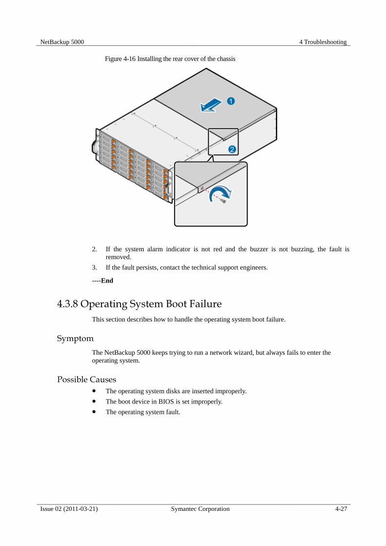
NetBackup 5000 4 Troubleshooting
Issue 02 (2011-03-21) Symantec Corporation 4-27
Figure 4-16 Installing the rear cover of the chassis
2. If the system alarm indicator is not red and the buzzer is not buzzing, the fault is
removed.
3. If the fault persists, contact the technical support engineers.
----End
4.3.8 Operating System Boot Failure
This section describes how to handle the operating system boot failure.
Symptom
The NetBackup 5000 keeps trying to run a network wizard, but always fails to enter the
operating system.
Possible Causes
The operating system disks are inserted improperly.
The boot device in BIOS is set improperly.
The operating system fault.

4 Troubleshooting NetBackup 5000
4-28 Symantec Corporation Issue 02 (2011-03-21)
Fault Diagnosis
Figure 4-17 Flow chart of handling the operating system boot failure
Procedure
Cause 1: The operating system disks are inserted improperly.
1. Reinsert the operating system disks. For details on how to reinstall the disk module, see
5.3 Replacing a Disk Module. Insert the operating system disks into the slot a and slot b
on the lower right corner of the NetBackup 5000.
2. After the disk module is reinstalled, if the NetBackup 5000 can enter the operating
system, the fault is removed.
3. If the fault persists, analyze the next cause.
Cause 2: The boot device setting in BIOS is improper.
1. Launch the NetBackup 5000 and press Del to enter the BIOS setting interface.
2. Select IPMIBoot.
3. Select RAID Card as 1st Boot Device, as shown in Figure 4-18.
4. Select Sent To BMC.

NetBackup 5000 4 Troubleshooting
Issue 02 (2011-03-21) Symantec Corporation 4-29
Figure 4-18 Setting the boot devices in BIOS
5. Exit BIOS by pressing F10. If the NetBackup 5000 boots from the system disk and
enters the operating system, the fault is removed.
6. If the fault persists, contact the technical support engineers.
Cause 3: The operating system fault.
1. Contact the technical support engineers.
----End
4.3.9 PD Manager Interface Slow to Respond
This section describes how to handle the fault that the PD Manage interface is slow to respond.
Symptom
1. The PD Manager interface is slow to respond when you log in.
2. After login, the function modules of the PD Manager responds slowly.
Possible Causes
The usage of system resources such as the CPU is high.
A name resolution error occurs.
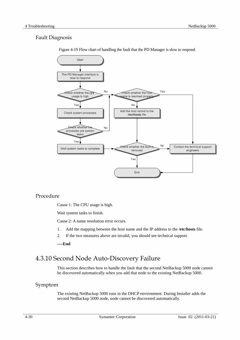
4 Troubleshooting NetBackup 5000
4-30 Symantec Corporation Issue 02 (2011-03-21)
Fault Diagnosis
Figure 4-19 Flow chart of handling the fault that the PD Manager is slow to respond
Procedure
Cause 1: The CPU usage is high.
Wait system tasks to finish.
Cause 2: A name resolution error occurs.
1. Add the mapping between the host name and the IP address to the /etc/hosts file.
2. If the two measures above are invalid, you should see technical support.
----End
4.3.10 Second Node Auto-Discovery Failure
This section describes how to handle the fault that the second NetBackup 5000 node cannot
be discovered automatically when you add that node to the existing NetBackup 5000.
Symptom
The existing NetBackup 5000 runs in the DHCP environment. During Installer adds the
second NetBackup 5000 node, node cannot be discovered automatically.
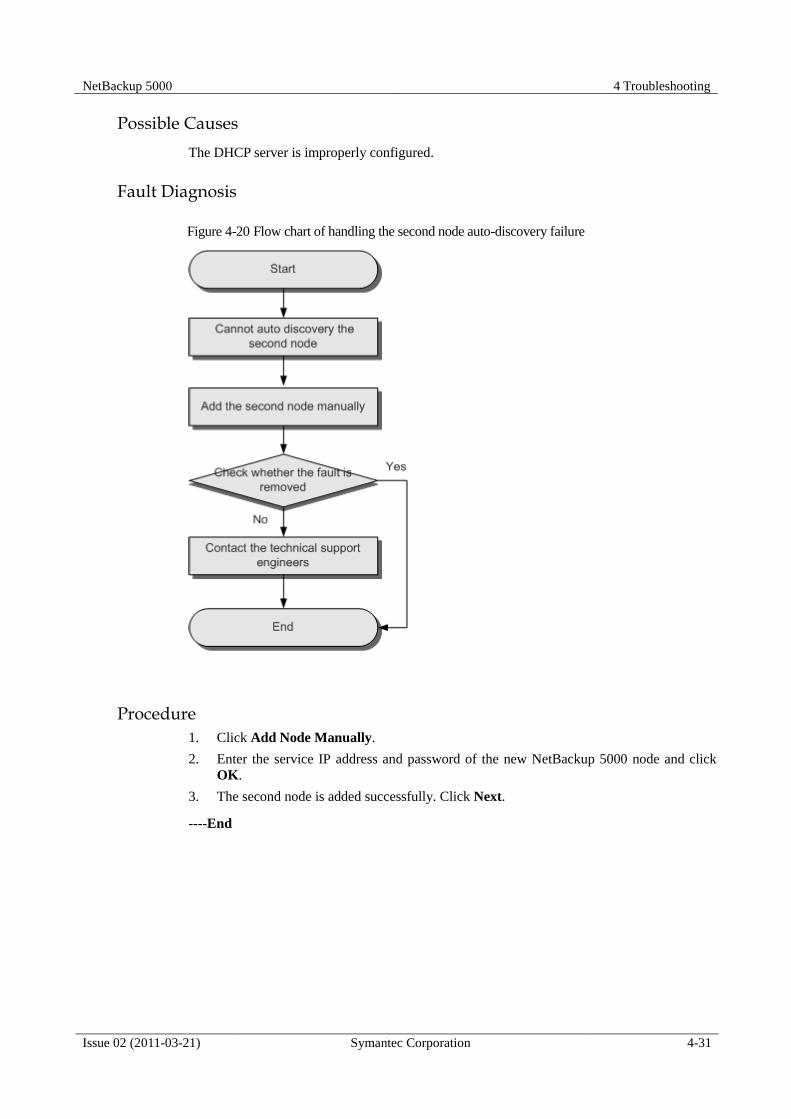
NetBackup 5000 4 Troubleshooting
Issue 02 (2011-03-21) Symantec Corporation 4-31
Possible Causes
The DHCP server is improperly configured.
Fault Diagnosis
Figure 4-20 Flow chart of handling the second node auto-discovery failure
Procedure
1. Click Add Node Manually.
2. Enter the service IP address and password of the new NetBackup 5000 node and click
OK.
3. The second node is added successfully. Click Next.
----End


NetBackup 5000 4 Troubleshooting
Issue 02 (2011-03-21) Symantec Corporation 4-1
4.3.11 PD Manager Login Failure
This section describes how to handle the fault that the PD Manager cannot be logged in to.
Symptom
When you want to log in to the PD Manager with an SPA node address, an error message,
instead of the login interface, is displayed.
Figure 4-21 Error message
Possible Causes
The related authentication in the NetBackup 5000 does not take effect.
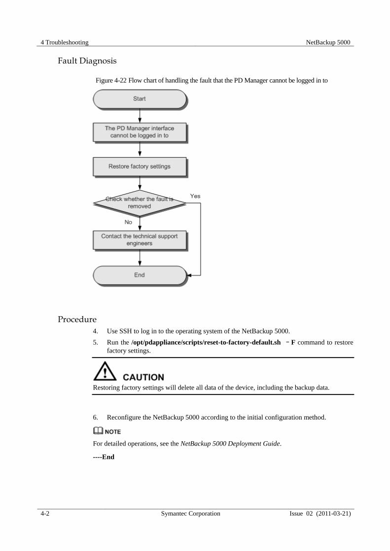
4 Troubleshooting NetBackup 5000
4-2 Symantec Corporation Issue 02 (2011-03-21)
Fault Diagnosis
Figure 4-22 Flow chart of handling the fault that the PD Manager cannot be logged in to
Procedure
4. Use SSH to log in to the operating system of the NetBackup 5000.
5. Run the /opt/pdappliance/scripts/reset-to-factory-default.sh –F command to restore
factory settings.
Restoring factory settings will delete all data of the device, including the backup data.
6. Reconfigure the NetBackup 5000 according to the initial configuration method.
For detailed operations, see the NetBackup 5000 Deployment Guide.
----End

NetBackup 5000 4 Troubleshooting
Issue 02 (2011-03-21) Symantec Corporation 4-1
4.3.12 Failure of MSM Automatic Refreshing
This section describes how to handle the fault that the data cannot be refreshed after the
NetBackup 5000 is configured through the MSM client.
Symptom
Symptom 1: After the MSM client connects to the NetBackup 5000, create a RAID
group and launch the initial operations, but the volume initialization process cannot be
refreshed dynamically.
Symptom 2: When you configure RAID cards, the MSM interface cannot refresh
dynamically.
Symptom 3: When you configure RAID cards, related operations cannot be viewed in
logs immediately.
Possible Causes
These symptoms exist on the Linux platform.
Fault Diagnosis
Figure 4-23 Flow chart of handling the fault that the MSM cannot refresh automatically

4 Troubleshooting NetBackup 5000
4-2 Symantec Corporation Issue 02 (2011-03-21)
Procedure
Symptom 1
1. On the RAID card management interface, choose Manage > Show Progress. The
Group Show Process window appears, on which you can view the initialization process.
2. To view the latest initialization process, close the Group Show Process window and
open it again.
Symptom 2
1. After completing the RAID card configuration, press F5 to refresh the MSM interface
manually.
Symptom 3
1. Close the current MSM interface.
2. Open the MSM interface again and re-log in to the related devices.
----End
4.3.13 Network Reconfiguration Failure
This section describes how to handle the fault that the network configuration fails after the
initial configuration is cancelled.
Symptom
Initialize the configuration with http:// 192.168.1.1/Installer and click Cancel during the
network initialization process, as shown in Figure 4-24.
The default management IP address is 192.168.1.1. If you change the IP address, use the new
IP address for configuration.

NetBackup 5000 4 Troubleshooting
Issue 02 (2011-03-21) Symantec Corporation 4-3
Figure 4-24 Network reconfiguration
When initialize the configuration with http://192.168.1.1/Installer again, the network
reconfiguration fails, as shown in Figure 4-25.
Figure 4-25 Network reconfiguration failure

4 Troubleshooting NetBackup 5000
4-4 Symantec Corporation Issue 02 (2011-03-21)
Possible Causes
Although the first configuration is cancelled on the interface, the initialization process may
still run in the background. If you run the initialization process again immediately, the second
initialization may fail.
Fault Diagnosis
Figure 4-26 Flow chart of troubleshooting network reconfiguration failure
Procedure
Method 1
1. Wait three to five minutes and perform reconfiguration.
Method 2

NetBackup 5000 4 Troubleshooting
Issue 02 (2011-03-21) Symantec Corporation 4-5
2. Use SSH to log in to the NetBackup 5000, restore factory settings with the
/opt/pdappliance/scripts/reset-to-factory-default.sh –F command, and launch the
initialization process again.
----End
4.3.14 PD Services Failure to Start Normally
This section describes how to handle the fault that PD services fail to start normally.
Symptom
After the service puredisk status command is run, some PD services are not in running state.
Possible Causes
The NetBackup 5000 is started after an improper shut down.

4 Troubleshooting NetBackup 5000
4-6 Symantec Corporation Issue 02 (2011-03-21)
Fault Diagnosis
Figure 4-27 Flow chart of handling the fault that PD services fail to start normally
Procedure
Method 1:
1. Use SSH to log in to the operating system of the NetBackup 5000.
2. Run the service puredisk restart command.
Method 2
1. Use SSH to log in to the operating system of the NetBackup 5000.
2. Run the reboot command.
----End

NetBackup 5000 4 Troubleshooting
Issue 02 (2011-03-21) Symantec Corporation 4-7
4.3.15 No Response of the MSM Management Interface
This section describes how to handle the fault that the MSM management interface does not
respond.
Symptom
When one of the system disks fail, hot spare disk A replaces the faulty system disk and
reconstructs with the normal system disk. If hot spare disk A fails during reconstructs, hot
spare disk B starts to reconstructs with the normal system disk. At this time, if you manage the
RAID card of the NetBackup 5000 through the MSM, the MSM management interface does
not respond. If you close and launch the MSM again, the MSM interface cannot connect to
the RAID cards of the NetBackup 5000.
Possible Causes
This fault is due to the defect of MSM management software for RAID cards.
Fault Diagnosis
Figure 4-28 Flow chart of handling the fault that the MSM management interface does not respond
Procedure
1. Use SSH to log in to the operating system of the NetBackup 5000.

4 Troubleshooting NetBackup 5000
4-8 Symantec Corporation Issue 02 (2011-03-21)
2. Remove the MSM from the NetBackup 5000 with the sh /usr/local/MegaRAID\
Storage\ Manager/uninstaller.sh command.
3. Upload the MSM installation file (a .zip file) to the NetBackup 5000 and decompress it
with the unzip 5.00-12_Linux_MSM.zip command.
4. Enter the MSM directory with the cd MSM command.
5. Decompress the MSM installation file with the tar -zxvf MSM_linux_installer-5.00-
12.tar.gz command.
6. Enter the disk directory with the cd disk command.
7. Launch automatic installation with the ./install.sh -s command.
----End
4.3.16 No CPU and Disk Information Displayed on ISM Interface
This section describes how to handle the fault that no CPU and disk information is displayed
on ISM management interface.
Symptom
Log in to the ISM management interface through Internet Explorer, and the following CPU
and disk information is displayed:
Can’t get CPU info, check if the SNMP Service is ON.
Can’t get disk info, check if the SNMP Service is ON.
Figure 4-29 ISM interface failing to display CPU and disk information
Possible Causes
The IPMI network port cannot communicate with the service network port.
The SNMP service is disabled.

NetBackup 5000 4 Troubleshooting
Issue 02 (2011-03-21) Symantec Corporation 4-9
Fault Diagnosis
Figure 4-30 Flow chart of handling the ISM CPU and disk information display failure
Procedure
1. Log in to the ISM management interface, click Set IPMI Network, and configure the IP
address of the IPMI network port so that the IPMI can communicate with the service port
of the NetBackup 5000, as shown in Figure 4-31.

4 Troubleshooting NetBackup 5000
4-10 Symantec Corporation Issue 02 (2011-03-21)
Figure 4-31 Configuring the IPMI network
2. Check whether the CPU and disk information can be displayed on the ISM management
interface. If not, go to the next step to enable the SNMP service of the NetBackup 5000.
3. Use SSH to log in to the NetBackup 5000 and replace the /etc/snmp/snmpd.conf with the
following snmpd.conf file.
4. Add port 161.
Run the vi /etc/puredisk/custom_iptables_rules command.
Add the following
udp 0.0.0.0/0 161
Behind these contents:
# e.g.: (example to accept snmp messages from 192.168.1.1)
# udp 192.168.1.1 161,162
5. Run the /opt/pdconfigure/scripts/installers/ChangeIPTables.sh command.
6. Log in to the ISM management interface, click Configure System, and confirm that the
RAID card status is Not installed, the operating system is Linux or Solaris, and the IP
address is the business IP address of NetBackup 5000 as shown in Figure 4-32.

NetBackup 5000 4 Troubleshooting
Issue 02 (2011-03-21) Symantec Corporation 4-11
Figure 4-32 Configuring System interface
7. At this time, the CPU and disk information can be displayed normally, as shown in
Figure 4-33.
Figure 4-33 Displaying the CPU and disk information
----End


NetBackup 5000 5 Replacing Parts
Issue 02 (2011-03-21) Symantec Corporation 5-1
5 Replacing Parts
About This Chapter
This chapter describes the preparations, precautions and procedures for replacing the client
replacement units (FRUs) of the NetBackup 5000.
5.1 Preparations for Replacing Parts
This section describes the preparations for replacing parts.
5.2 Precautions for Replacing Parts
This section describes the precautions for replacing parts.
5.3 Replacing a Disk Module
This section describes how to replace a disk module.
5.4 Replacing a Fan Module
This section describes how to replace a fan module.
5.5 Replacing a power supply
This section describes how to replace a power supply.
5.6 Replacing a RAID Card
This section describes how to replace a RAID card.
5.7 Replacing a NIC
This section describes how to replace a NIC.
5.8 Replacing an Expansion Board
This section describes how to replace an expansion board.
5.9 Replacing a Memory Bank
This section describes how to replace a memory bank.
5.10 Replacing a CPU
This section describes how to replace a central processing unit (CPU).
5.11 Replacing a Main Board

5 Replacing Parts NetBackup 5000
5-2 Symantec Corporation Issue 02 (2011-03-21)
This section describes how to replace a main board.
5.1 Preparations for Replacing Parts
This section describes the preparations for replacing parts.
Before installing or replacing parts, do as follows:
Confirm the feasibility of the operation.
− Ensure that the new parts are in good condition and free from defects such as
oxidation, chemical erosion, loose units, and shipment damage.
− Ensure that you have learned the operations and basic skills of installing and
replacing parts by reading this guide.
Prepare parts and tools.
− Prepare the parts for the installation and replacement.
− Prepare necessary tools such as Philips rewdriver and ESD-preventive wrist strap.
The provider offers the tool list, but you need to negotiate with the provider to decide
who provides the tools.
− When carrying or moving parts, use dedicated ESD-preventive plastic bags.
− In the routine maintenance for the NetBackup 5000, arrange and register the parts
properly and send the faulty ones for repair in time.
Confirm the target locations of the parts.
Find and label the cabinet and the NetBackup 5000 that house the parts to be replaced to
avoid improper operations.
For difficult or serious faults during parts replacement, contact the technical support engineers.
5.2 Precautions for Replacing Parts
This section describes the precautions for replacing parts.
Only professional maintenance personnel are allowed to remove the middle or rear cover
of the chassis to replace the parts in the system.
Before removing the middle or rear cover of the chassis to replace the parts in the system,
power off the NetBackup 5000 and disconnect the NetBackup 5000 from the power
sockets and external devices.
Powering off the NetBackup 5000 will affect the service running, so be cautious when
doing so.

NetBackup 5000 5 Replacing Parts
Issue 02 (2011-03-21) Symantec Corporation 5-3
Do not touch the connectors of power cables or communication cables. Otherwise, the human
body may get an electrical shock.
When replacing the parts, pay attention to the following:
Wear an ESD-preventive wrist strap, ESD-preventive gloves or ESD-preventive clothes
to prevent static electricity from injuring your body or damaging the device.
Tighten your sleeves or roll them above your elbow when replacing parts. For the safety
purpose, do not wear jewelry, watch, metal-frame glasses, or clothes with metal buttons.
Keep the area that houses the parts tidy.
Do not insert the parts forcibly; otherwise, too much force may damage the appearance
or the parts (such as pin bending or pin short circuit).
Ensure that the NetBackup 5000 is properly grounded.
5.3 Replacing a Disk Module
This section describes how to replace a disk module.
Impact on the System
Ensure that service data and system information on the disk to be replaced are backed up.
Prerequisite
The disk module for the replacement is available.
The disk module to be replaced is located.
Log collection, refer to 7.2 Collecting Log Information.
Tools and Materials
ESD-preventive gloves
ESD-preventive wrist strap
ESD-preventive clothes
ESD-preventive bag
Tag
Precaution
To avoid damaging the disk or the connector, be cautious to remove or install the disk
with even force.
When removing a disk, first pull the disk out of the slot. Wait at least 30 seconds before
completely pulling the disk out of the chassis.
When removing and inserting a disk, ensure that the interval is longer than one minute;
that is, after removing a disk, wait at least one minute before inserting the disk, or after
inserting a disk, wait at least one minute before removing the disk. In this way, the disk
will not be damaged.

5 Replacing Parts NetBackup 5000
5-4 Symantec Corporation Issue 02 (2011-03-21)
To avoid data loss, only replace the disk whose online status indicator is red.
Make sure the disk module for the replacement is produced by Seagate, the Seagate logo
is as shown in Figure 5-1.
Figure 5-1 Seagate logo
Procedure
Step 1 Wear ESD-preventive clothes, ESD-preventive wrist strap, and ESD-preventive gloves. To
wear the ESD-preventive wrist strap, do as follows:
1. Stretch your hand through the ESD-preventive wrist strap.
2. Fasten the buckle and ensure that the ESD-preventive wrist strap fully touches your skin.
An ESD-preventive wrist strap may carry a plug or metal clip.
− For the ESD-preventive wrist strap with a plug, insert the grounding connector of the
ESD-preventive wrist strap into the ESD socket of the cabinet, as shown in Figure 5-
2
Figure 5-2 Wearing the ESD-preventive wrist strap with a plug
− For the ESD-preventive wrist strap with a metal clip, clip the metal clip of the wrist
strap to the square hole on the side of the cabinet, as shown in Figure 5-3.

NetBackup 5000 5 Replacing Parts
Issue 02 (2011-03-21) Symantec Corporation 5-5
Figure 5-3 Wearing the ESD-preventive wrist strap with a metal clip
3. Ensure that the buckle of the ESD-preventive wrist strap is fastened and the grounding
connector is inserted tightly to the ESD jack or the metal clip is tightly clipped to the
square hole on the cabinet.
Step 2 Press the buckle on the handle to spring up the handle of the disk module, as shown in step (1)
in Figure 5-4.
Step 3 Open the handle, as shown in step (2) in Figure 5-4.
Step 4 Slowly pull out the disk module, as shown in step (3) in Figure 5-4.

5 Replacing Parts NetBackup 5000
5-6 Symantec Corporation Issue 02 (2011-03-21)
Figure 5-4 Removing a disk module
Step 5 Place the removed disk module into the ESD-preventive bag. The operation of removing the
disk module is complete.
Step 6 Take the disk module to be installed out of the ESD-preventive bag.
Step 7 Insert the disk module into an empty slot, as shown in step (1) in Figure 5-5.
Fully open the handle; otherwise the disk module cannot be completely inserted.
Step 8 Close the disk handle, as shown in step (2) in Figure 5-5.

NetBackup 5000 5 Replacing Parts
Issue 02 (2011-03-21) Symantec Corporation 5-7
Figure 5-5 Installing a disk module
Step 9 Check whether the installation is successful by observing the disk read/write indicator and
disk online indicator, as shown in Table 4-1.
If the disk read/write indicator blinks and the online indicator is on and green, it indicates
a successful installation.
If the disk online indicator is off, it indicates that the disk module may be improperly
installed. In this case, repeat Step 2 to Step 4 to remove the disk, wait one minute, and
reinstall the disk module.
If the disk read/write indicator is always off, it indicates that the disk module that is
installed is faulty. In this case, replace the disk module with a new one.
----End
Postrequisite
After the disk module is replaced, label the replaced disk module for the convenience of
subsequent handling. After the disk module is replaced, perform the following procedure:
1. Use SSH to log in to the operating system of the NetBackup 5000, the default login
credentials: root/root.
2. Run the /opt/MegaRAID/MegaCli/MegaCli64 -AdpgetProp CopyBackDsbl –a0
command to check whether the copyback function is enabled or not, if the value is
Enabled, skip Step 3, as shown in Figure 5-6.

5 Replacing Parts NetBackup 5000
5-8 Symantec Corporation Issue 02 (2011-03-21)
Figure 5-6 Getting the property of copyback function
3. Run the /opt/MegaRAID/MegaCli/MegaCli64 -AdpSetProp -CopyBackDsbl -0 –a0
command to enable copyback function.
4. Open the MSM software to connect the device whose disk module has been replaced.
5. Select the Physical in left pane.
6. Check the status of original Hotspare disks, if one of original Hotspare disks is
rebuilding, waiting for the rebuilding completed.
1. The original Hotspare disks are slot 2 and slot 3
2. The following steps should be done after the rebuilding is completed.
7. Click Manage--Refresh, if the status of the disk inserted newly is Replacing, skip
Postrequisite 8 and Postrequisite 9.
8. Select the disk rebuilt in the left pane, and click the mouse right key, select Replace
Physical Drive command, as shown in Figure 5-7.
Figure 5-7 Setting Replace Physical Drive
9. Click Manage--Refresh, make sure the disk status is Replacing.
Set the preceding operations through MegaRAID Storage Manager, MegaCLI or WebBIOS.
For details, see User’s Guide MegaRAID SAS Software.
----End
5.4 Replacing a Fan Module
This section describes how to replace a fan module.

NetBackup 5000 5 Replacing Parts
Issue 02 (2011-03-21) Symantec Corporation 5-9
Impact on the System
Only professional maintenance personnel are allowed to remove the middle or rear cover
of the chassis to replace the parts in the system.
Before removing the middle or rear cover of the chassis to replace the parts in the system,
power off the NetBackup 5000 and disconnect the NetBackup 5000 from the power
sockets and external devices.
Powering off the NetBackup 5000 will affect the service running, so be cautions when
doing so.
Before the fan module is replaced, the NetBackup 5000 needs to be powered off, so the
services of the NetBackup 5000 will be affected.
During the replacement of the fan module, the services of the NetBackup 5000 will be affected.
Therefore, it is recommended to replace the fan module when the service load is not heavy.
Prerequisite
The fan module for the replacement is available.
The fan module to be replaced is located.
Before replacing the fan module, power off the NetBackup 5000 and disconnect it from
the power sockets and external devices.
Tools and Materials
ESD-preventive gloves
ESD-preventive wrist strap
ESD-preventive clothes
ESD-preventive bag
Tag
Precaution
The NetBackup 5000 is supported by two power supplies. Cut off both of the power
supplies when powering off the NetBackup 5000.
The fan module is located in the middle of the chassis, so the middle cover of the chassis
needs to be removed before the replacement of the fan module.
Procedure
Step 1 Wear the ESD-preventive clothes, ESD-preventive wrist strap, and ESD-preventive
gloves. For details on how to wear the ESD-preventive wrist strap, see Wearing the
ESD-Preventive Wrist Strap in 5.3 “Replacing a Disk Module”.
Step 2 Power off the NetBackup 5000, and disconnect it from the power sockets and external
devices.

5 Replacing Parts NetBackup 5000
5-10 Symantec Corporation Issue 02 (2011-03-21)
Step 3 Smoothly pull the NetBackup 5000 out of the cabinet, and lay it onto a grounded and
ESD-free operating platform.
To remove the NetBackup 5000 from the cabinet, do as follows:
1. Loosen the four screws that are used to fix the NetBackup 5000 counterclockwise, as
shown in step (1) in Figure 5-8.
2. Hold the handles on both sides of the chassis and pull out the NetBackup 5000 slowly, as
shown in step (2) in Figure 5-8.
Figure 5-8 Removing the NetBackup 5000 from the cabinet
Step 4 Loosen the six screws on the middle cover of the chassis counterclockwise, as shown in step
(1) in Figure 5-9.
Step 5 Lightly lift the middle cover of the chassis, as shown in step (2) in Figure 5-9.
Step 6 Remove the middle cover from the chassis, as shown in step (3) in Figure 5-9.

NetBackup 5000 5 Replacing Parts
Issue 02 (2011-03-21) Symantec Corporation 5-11
Figure 5-9 Removing the middle cover from the chassis
Step 7 Press the spring leaf and hold the handle of the fan module, pull the fan module upward and
remove it from the chassis, as shown in Figure 5-10.
Figure 5-10 Removing a fan module
Step 8 Put the removed fan module into the ESD-preventive bag. The operation of removing the fan
module is complete.
Step 9 Take the fan module to be installed out of the ESD-preventive bag.
Step 10 Insert the fan module into the empty slot until it is tightly inserted, as shown in Figure 5-11.

5 Replacing Parts NetBackup 5000
5-12 Symantec Corporation Issue 02 (2011-03-21)
Figure 5-11 Installing a fan module
Step 11 Place the middle cover of the chassis in the corresponding place on the top of the NetBackup
5000 chassis, as shown in step (1) in Figure 5-12.
Step 12 Shut the middle cover of the chassis, as shown in step (2) in Figure 5-12.
Step 13 Fasten the six screws clockwise on the middle cover of the chassis, as shown in step (3) in
Figure 5-12.
Figure 5-12 Installing the middle cover of the chassis
Step 14 Install the NetBackup 5000 into the cabinet.
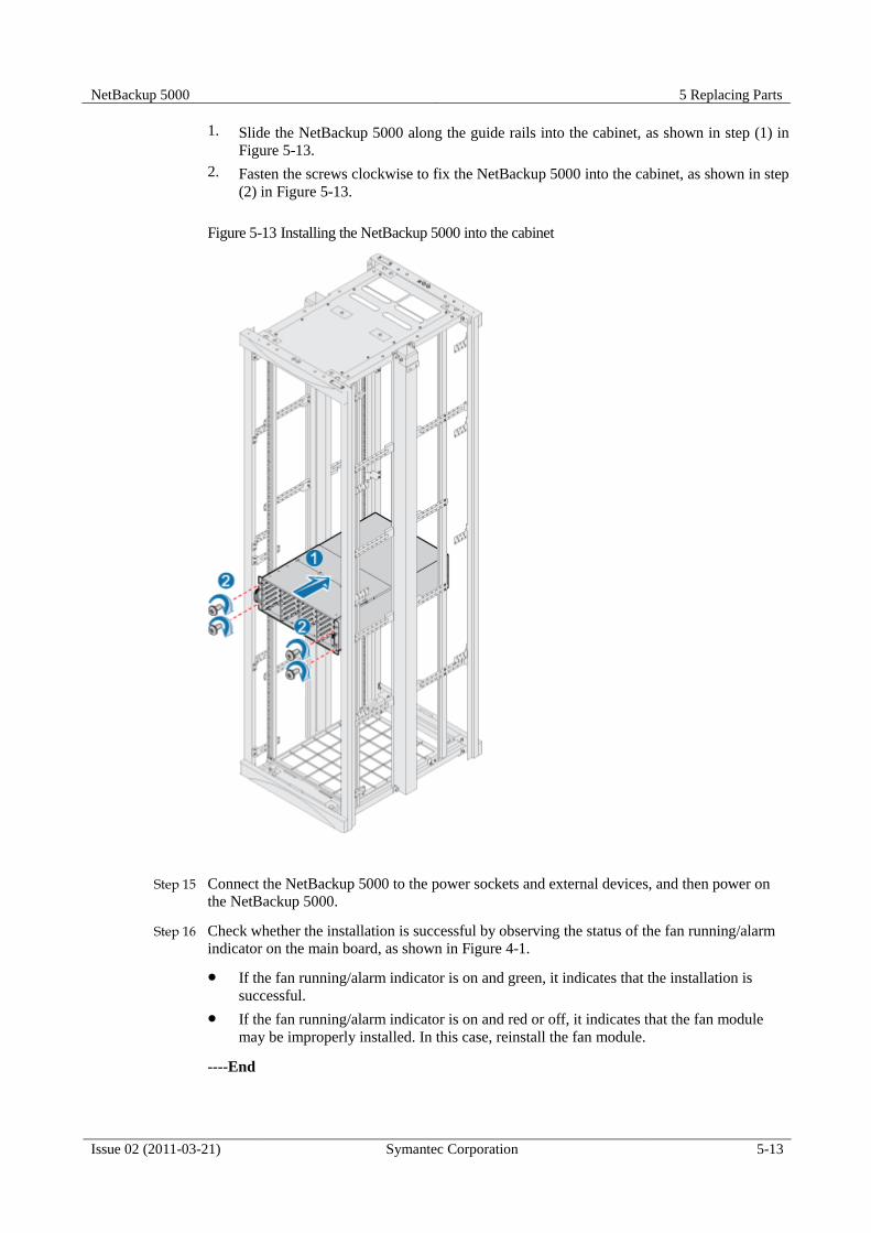
NetBackup 5000 5 Replacing Parts
Issue 02 (2011-03-21) Symantec Corporation 5-13
1. Slide the NetBackup 5000 along the guide rails into the cabinet, as shown in step (1) in
Figure 5-13.
2. Fasten the screws clockwise to fix the NetBackup 5000 into the cabinet, as shown in step
(2) in Figure 5-13.
Figure 5-13 Installing the NetBackup 5000 into the cabinet
Step 15 Connect the NetBackup 5000 to the power sockets and external devices, and then power on
the NetBackup 5000.
Step 16 Check whether the installation is successful by observing the status of the fan running/alarm
indicator on the main board, as shown in Figure 4-1.
If the fan running/alarm indicator is on and green, it indicates that the installation is
successful.
If the fan running/alarm indicator is on and red or off, it indicates that the fan module
may be improperly installed. In this case, reinstall the fan module.
----End

5 Replacing Parts NetBackup 5000
5-14 Symantec Corporation Issue 02 (2011-03-21)
Postrequisite
After the fan module is replaced, label the replaced fan module for the convenience of
subsequent operations.
5.5 Replacing a Power Supply
This section describes how to replace a power supply.
Impact on the System
During the power supply replacement, ensure that service data and system information are
backed up.
Prerequisite
The power supply for the replacement is available.
The power supply to be replaced is located.
Tools and Materials
ESD-preventive gloves
ESD-preventive wrist strap
ESD-preventive clothes
ESD-preventive bag
Tag
Precaution
Do not remove or insert the power supply forcibly; otherwise, too much force may
damage the physical appearance or plug-ins.
Remove the faulty power supply and install a new one within two minutes.
When installing a power supply, do not put your fingers on the handle of the power
supply; otherwise, your fingers may be clipped.
Procedure
Step 1 Wear ESD-preventive clothes, ESD-preventive wrist straps, and ESD-preventive
gloves. For details on how to wear the ESD-preventive wrist strap, see Wearing the
ESD-Preventive Wrist Strap in 5.3 “Replacing a Disk Module”.
Step 2 Locate the faulty power supply to be replaced by observing the status of the power
supply running/alarm indicator, as shown in Table 4-1.
Step 3 Press the power supply spring leaf and hold the power supply handle. Then slowly pull
the power supply out, as shown in steps (1) and (2) in Figure 5-14.

NetBackup 5000 5 Replacing Parts
Issue 02 (2011-03-21) Symantec Corporation 5-15
Figure 5-14 Removing a power supply
Step 4 Place the removed power supply into the ESD-preventive bag. The operation of
removing the power supply is complete.
Step 5 Take the power supply to be installed out of the ESD-preventive bag.
Step 6 Insert the power supply to the empty slot until it is fully placed, as shown in Figure 5-
15.

5 Replacing Parts NetBackup 5000
5-16 Symantec Corporation Issue 02 (2011-03-21)
Figure 5-15 Installing a power supply
Step 7 Connect the NetBackup 5000 to the power sockets.
Step 8 Check whether the installation is successful by observing the status of the power
running/alarm indicator, as shown in Table 4-1.
If the power running/alarm indicator is on and green, it indicates that the installation is
successful.
If the power running/alarm indicator is on and red or off, it indicates that the power
supply may be improperly installed. In this case, reinstall the power supply.
----End
Postrequisite
After the power supply is replaced, label the replaced power supply for the convenience of
subsequent operations.
5.6 Replacing a Mini SAS Cable
This section describes how to replace a Mini SAS (Serial Attached SCSI) Cable.
Impact on the System

NetBackup 5000 5 Replacing Parts
Issue 02 (2011-03-21) Symantec Corporation 5-17
Only professional maintenance personnel are allowed to remove the middle or rear cover
of the chassis to replace the parts in the system.
Before removing the middle or rear cover of the chassis to replace the parts in the system,
power off the NetBackup 5000 and disconnect the NetBackup 5000 from the power
sockets and external devices.
Powering off the NetBackup 5000 will affect the service running. Perform this operation
with caution!
Power off the NetBackup 5000 before replacing the Mini SAS cable; otherwise, the services
of the NetBackup 5000 may be affected
Prerequisite
The Mini SAS cable to be replaced is available
Before replacing the Mini SAS cable, power off the NetBackup 5000 and disconnect the
NetBackup 5000 from the power sockets and external devices.
Tools and Materials
Philips screwdriver
ESD-preventive gloves
ESD-preventive wrist strap
ESD-preventive clothes
ESD-preventive bag
Tag
Precaution
The NetBackup 5000 is supported by two power supplies. Cut off both of the power
supplies when powering off the NetBackup 5000.
Connect the RAID card to the expansion board by mini SAS cable in cross connection,
that is, one end of the mini SAS cable connects to the mini SAS connector at the left of
the RAID card and the other end connects to the mini SAS connector below the
expansion board.
When connecting the mini SAS cables, ensure proper connection; otherwise, you may
fail to find all the disks after replace the Mini SAS cable.
Procedure
Step 1 Wear the ESD-preventive clothes, ESD-preventive wrist strap, and ESD-preventive
gloves. For details on how to wear the ESD-preventive wrist strap, see Wearing the
ESD-Preventive Wrist Strap in 5.3 “Replacing a Disk Module”.
Step 2 Power off the NetBackup 5000 and disconnect the NetBackup 5000 from the power
sockets and external devices.
Step 3 Smoothly pull the NetBackup 5000 out of the cabinet, and lay the NetBackup 5000 on
a grounded and ESD-free operating platform. For details, see Step 3 in 5.4 “Replacing
a Fan Module”.

5 Replacing Parts NetBackup 5000
5-18 Symantec Corporation Issue 02 (2011-03-21)
Step 4 Open the rear cover of the chassis.
1. Loosen the two screws on the rear cover of the chassis counterclockwise, as shown in
step (1) in Figure 5-16.
2. Smoothly push the rear cover of the chassis to the back panel of the chassis and hold on
the two sides of the rear cover of the chassis to remove the rear cover from the
NetBackup 5000, as shown in step (2) in Figure 5-16.
Figure 5-16 Removing the rear cover of the chassis
Step 5 Pull out the mini SAS cable which connects the RAID card, as shown in step (1) in
Figure 5-17.
Step 6 Pull out the mini SAS cable which connects the expansion board, as shown in step (2)
in Figure 5-17..

NetBackup 5000 5 Replacing Parts
Issue 02 (2011-03-21) Symantec Corporation 5-19
Figure 5-17 Removing a Mini SAS cable
Step 7 Place the removed Mini SAS cable into the ESD-preventive bag. The operation of
removing the Mini SAS cable is complete.
Step 8 Take the Mini SAS cable to be installed out of the ESD-preventive bag.
Step 9 Connect the mini SAS cable to the expansion board, as shown in step (1) in Figure 5-
18.
Step 10 Connect the mini SAS cable to the RAID card, as shown in step (2) in Figure 5-18.

5 Replacing Parts NetBackup 5000
5-20 Symantec Corporation Issue 02 (2011-03-21)
Figure 5-18 Installing a RAID card
Step 11 Install the rear cover of the chassis.
1. Put the rear cover of the chassis on the top of the chassis and slightly backward, so that
the tabs on the two sides can be inserted into the hooks of the chassis and the rear cover
can be placed flatly on the chassis.
2. Smoothly push the rear cover of the chassis to the disk module until the rear cover is in
position, as shown in step (1) in Figure 5-19.
3. Fasten the two screws at the two sides of the rear cover of the chassis clockwise, as
shown in step (2) in Figure 5-19.

NetBackup 5000 5 Replacing Parts
Issue 02 (2011-03-21) Symantec Corporation 5-21
Figure 5-19 Installing the rear cover of the chassis
Step 12 Install the NetBackup 5000 into the cabinet. For details, see Step 14 in 5.4 “Replacing
a Fan Module”.
Step 13 After connecting the NetBackup 5000 to the power socket and external devices, power
on the NetBackup 5000.
----End
Postrequisite
After the Mini SAS cable is replaced, label the replaced Mini SAS cable for the convenience
of subsequent handling
After the Mini SAS cable is replaced, power on the device, make sure there have follow
message after RAID card self-test.

5 Replacing Parts NetBackup 5000
5-22 Symantec Corporation Issue 02 (2011-03-21)
Figure 5-20 RAID card detect all disks
----End
5.7 Replacing a RAID Card
This section describes how to replace a RAID card.
Impact on the System
Only professional maintenance personnel are allowed to remove the middle or rear cover
of the chassis to replace the parts in the system.
Before removing the middle or rear cover of the chassis to replace the parts in the system,
power off the NetBackup 5000 and disconnect the NetBackup 5000 from the power
sockets and external devices.
Powering off the NetBackup 5000 will affect the service running. Perform this operation
with caution!
Power off the NetBackup 5000 before replacing the RAID (Redundant Arrays of Independent
Disks) card; otherwise, the services of the NetBackup 5000 may be affected
Prerequisite
The RAID card to be replaced is available
Before replacing the RAID card, power off the NetBackup 5000 and disconnect the
NetBackup 5000 from the power sockets and external devices.
Tools and Materials
Philips screwdriver
ESD-preventive gloves
ESD-preventive wrist strap

NetBackup 5000 5 Replacing Parts
Issue 02 (2011-03-21) Symantec Corporation 5-23
ESD-preventive clothes
ESD-preventive bag
Tag
Precaution
The NetBackup 5000 is supported by two power supplies. Cut off both of the power
supplies when powering off the NetBackup 5000.
Connect the RAID card to the expansion board by a mini SAS cable in cross connection,
that is, one end of the mini SAS cable connects to the mini SAS connector at the left of
the RAID card and the other end connects to the mini SAS connector below the
expansion board.
When connecting the mini SAS cables, ensure proper connection; otherwise, you may
fail to find all the disks after installing the RAID card.
Procedure
Step 1 Wear the ESD-preventive clothes, ESD-preventive wrist strap, and ESD-preventive
gloves. For details on how to wear the ESD-preventive wrist strap, see Wearing the
ESD-Preventive Wrist Strap in 5.3 “Replacing a Disk Module”.
Step 2 Power off the NetBackup 5000 and disconnect the NetBackup 5000 from the power
sockets and external devices.
Step 3 Smoothly pull the NetBackup 5000 out of the cabinet, and lay the NetBackup 5000 on
a grounded and ESD-free operating platform. For details, see Step 3 in 5.4 “Replacing
a Fan Module”.
Step 4 Open the rear cover of the chassis. For details, see Step 4 in 5.6 “Replacing a Mini
SAS Cable”.
Step 5 Pull out the mini SAS cable which connects the RAID card, as shown in step (1) in
Figure 5-21.
Step 6 Loosen the screws that are used to fix the chassis counterclockwise, as shown in step
(2) in Figure 5-21.
Step 7 Remove the RAID card upward from the PCIe slot, as shown in step (3) in Figure 5-21.
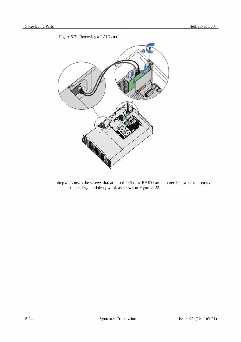
5 Replacing Parts NetBackup 5000
5-24 Symantec Corporation Issue 02 (2011-03-21)
Figure 5-21 Removing a RAID card
Step 8 Loosen the screws that are used to fix the RAID card counterclockwise and remove
the battery module upward, as shown in Figure 5-22.

NetBackup 5000 5 Replacing Parts
Issue 02 (2011-03-21) Symantec Corporation 5-25
Figure 5-22 Removing and installing the battery module of the RAID card
Step 9 Place the removed RAID card into the ESD-preventive bag. The operation of
removing the RAID card is complete.
Step 10 Take the RAID card to be installed out of the ESD-preventive bag.
Step 11 Aim the battery module at the J10 interface of the RAID card and then fasten the
screws clockwise, as shown in Figure 5-22.
Step 12 Aim at the PCIe slot and insert the RAID card to the PCIe slot downward vertically, as
shown in step (1) in Figure 5-23.
Step 13 Fasten the screws clockwise and fix the RAID card in the chassis, as shown in step (2)
in Figure 5-23.
Step 14 Connect the mini SAS cable to the RAID card, as shown in step (3) in Figure 5-23.
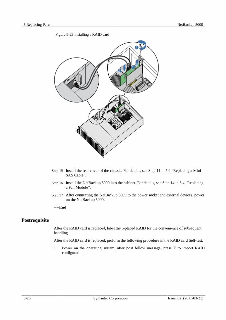
5 Replacing Parts NetBackup 5000
5-26 Symantec Corporation Issue 02 (2011-03-21)
Figure 5-23 Installing a RAID card
Step 15 Install the rear cover of the chassis. For details, see Step 11 in 5.6 “Replacing a Mini
SAS Cable”.
Step 16 Install the NetBackup 5000 into the cabinet. For details, see Step 14 in 5.4 “Replacing
a Fan Module”.
Step 17 After connecting the NetBackup 5000 to the power socket and external devices, power
on the NetBackup 5000.
----End
Postrequisite
After the RAID card is replaced, label the replaced RAID for the convenience of subsequent
handling
After the RAID card is replaced, perform the following procedure in the RAID card Self-test:
1. Power on the operating system, after post follow message, press F to import RAID
configuration;
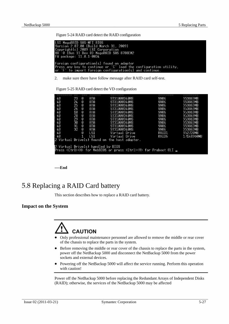
NetBackup 5000 5 Replacing Parts
Issue 02 (2011-03-21) Symantec Corporation 5-27
Figure 5-24 RAID card detect the RAID configuration
2. make sure there have follow message after RAID card self-test.
Figure 5-25 RAID card detect the VD configuration
----End
5.8 Replacing a RAID Card battery
This section describes how to replace a RAID card battery.
Impact on the System
Only professional maintenance personnel are allowed to remove the middle or rear cover
of the chassis to replace the parts in the system.
Before removing the middle or rear cover of the chassis to replace the parts in the system,
power off the NetBackup 5000 and disconnect the NetBackup 5000 from the power
sockets and external devices.
Powering off the NetBackup 5000 will affect the service running. Perform this operation
with caution!
Power off the NetBackup 5000 before replacing the Redundant Arrays of Independent Disks
(RAID); otherwise, the services of the NetBackup 5000 may be affected

5 Replacing Parts NetBackup 5000
5-28 Symantec Corporation Issue 02 (2011-03-21)
Prerequisite
The RAID card to be replaced is available
Before replacing the RAID card, power off the NetBackup 5000 and disconnect the
NetBackup 5000 from the power sockets and external devices.
Tools and Materials
Philips screwdriver
ESD-preventive gloves
ESD-preventive wrist strap
ESD-preventive clothes
ESD-preventive bag
Tag
Precaution
The NetBackup 5000 is supported by two power supplies. Cut off both of the power
supplies when powering off the NetBackup 5000.
Connect the RAID card to the expansion board by a mini SAS cable in cross connection,
that is, one end of the mini SAS cable connects to the mini SAS connector at the left of
the RAID card and the other end connects to the mini SAS connector below the
expansion board.
When connecting the mini SAS cables, ensure proper connection; otherwise, you may
fail to find all the disks after installing the RAID card.
Procedure
Step 1 Wear the ESD-preventive clothes, ESD-preventive wrist strap, and ESD-preventive
gloves. For details on how to wear the ESD-preventive wrist strap, see Wearing the
ESD-Preventive Wrist Strap in 5.3 “Replacing a Disk Module”.
Step 2 Power off the NetBackup 5000 and disconnect the NetBackup 5000 from the power
sockets and external devices.
Step 3 Smoothly pull the NetBackup 5000 out of the cabinet, and lay the NetBackup 5000 on
a grounded and ESD-free operating platform. For details, see Step 3 in 5.4 “Replacing
a Fan Module”.
Step 4 Open the rear cover of the chassis. For details, see Step 4 in 5.6 “Replacing a Mini
SAS Cable”.
Step 5 Pull out the mini SAS cable which connects the RAID card, remove the RAID card,
remove the RAID card battery. For details, see Step 5 to Step 8 in 5.7 “Replacing a
RAID Card”.
Step 6 Place the removed RAID card battery into the ESD-preventive bag. The operation of
removing the RAID card battery is complete.
Step 7 Take the RAID card battery to be installed out of the ESD-preventive bag.
Step 8 Install the RAID card battery, install the RAID card to PCIe-slot, connect the mini
SAS cable to the RAID card. For details, see Step 11 to Step 14 in 5.7 “Replacing a
RAID Card”.

NetBackup 5000 5 Replacing Parts
Issue 02 (2011-03-21) Symantec Corporation 5-29
Step 9 Install the rear cover of the chassis. For details, see Step 11 in 5.6 “Replacing a Mini
SAS Cable”.
Step 10 Install the NetBackup 5000 into the cabinet. For details, see Step 14 in 5.4 “Replacing
a Fan Module”.
Step 11 After connecting the NetBackup 5000 to the power socket and external devices, power
on the NetBackup 5000.
----End
Postrequisite
After the RAID card battery is replaced, label the replaced RAID battery for the convenience
of subsequent handling.
5.9 Replacing a NIC
This section describes how to replace a NIC.
Impact on the System
Only professional maintenance personnel are allowed to remove the middle or rear cover
of the chassis to replace the parts in the system.
Before removing the middle or rear cover of the chassis to replace the parts in the system,
power off the NetBackup 5000 and disconnect the NetBackup 5000 from the power
sockets and external devices.
Powering off the NetBackup 5000 will affect the service running. Perform this operation
with caution!
Power off the NetBackup 5000 before replacing the NIC; otherwise, the services of the
NetBackup 5000 may be affected
Prerequisite
The NIC to be replaced is available.
Before replacing the NIC, power off the NetBackup 5000 and disconnect it from the
power sockets and external devices.
Tools and Materials
Philips screwdriver
ESD-preventive gloves
ESD-preventive wrist strap
ESD-preventive clothes
ESD-preventive bag

5 Replacing Parts NetBackup 5000
5-30 Symantec Corporation Issue 02 (2011-03-21)
Tag
Precaution
The NetBackup 5000 is supported by two power supplies. Cut off both of the power supplies
when powering off the NetBackup 5000.
Procedure
Step 1 Wear the ESD-preventive clothes, ESD-preventive wrist strap, and ESD-preventive
gloves. For details on how to wear the ESD-preventive wrist strap, Wearing the ESD-
Preventive Wrist Strap in 5.3 “Replacing a Disk Module”.
Step 2 Power off the NetBackup 5000, and then disconnect the NetBackup 5000 from the
power sockets and external devices.
Step 3 Smoothly pull the NetBackup 5000 out of the cabinet, and lay the NetBackup 5000 on
a grounded and ESD-free operating platform. For details, Step 3 in 5.4 “Replacing a
Fan Module".
Step 4 Open the rear cover of the chassis. For details, see Step 4 in 5.6 “Replacing a Mini
SAS Cable”.
Step 5 Loosen the screws that are used to fix the chassis counterclockwise, as shown in step
(1) in Figure 5-26.
Step 6 Remove the NIC upward from the PCIe slot, as shown in step (2) in Figure 5-26.
Figure 5-26 Removing a NIC

NetBackup 5000 5 Replacing Parts
Issue 02 (2011-03-21) Symantec Corporation 5-31
Step 7 Place the removed NIC into the ESD-preventive bag. The operation of removing the
NIC is complete.
Step 8 Take the NIC to be installed out of the ESD-preventive bag.
Step 9 Aim at the PCIe slot and insert the NIC to the PCIe slot downward vertically, as
shown in step (1) in Figure 5-27.
Step 10 Fasten the screws clockwise and fix the NIC in the chassis, as shown in step (2) in
Figure 5-27.
Figure 5-27 Installing a NIC
Step 11 Install the rear cover of the chassis. For details, see Step 11 in 5.6 “Replacing a Mini
SAS Cable”.
Step 12 Install the NetBackup 5000 into the cabinet. For details, Step 14 in 5.4 “Replacing a
Fan Module".
Step 13 After connecting the NetBackup 5000 to the power socket and external devices, power
on the NetBackup 5000.
Step 14 Check whether the installation is successful by observing the status of the link/active
indicator of the NIC, as shown in Table 4-1.
If the link/active indicator is on and green, it indicates a successful installation.
If the link/active indicator is off, it indicates that the NIC may be improperly installed.
Pull out the NIC and install it again.
----End

5 Replacing Parts NetBackup 5000
5-32 Symantec Corporation Issue 02 (2011-03-21)
Postrequisite
After the NIC is replaced, label the replaced NIC for the convenience of subsequent handling.
5.10 Replacing a DIMM
This section describes how to replace a DIMM.
Impact on the System
Only professional maintenance personnel are allowed to remove the middle or rear cover
of the chassis to replace the parts in the system.
Before removing the middle or rear cover of the chassis to replace the parts in the system,
power off the NetBackup 5000 and disconnect the NetBackup 5000 from the power
sockets and external devices.
Powering off the NetBackup 5000 will affect the service running. Perform this operation
with caution!
Power off the NetBackup 5000 before replacing the DIMM; otherwise, the services of the
NetBackup 5000 may be affected.
Prerequisite
The DIMM to be replaced is available
The DIMM to be replaced is located.
Before replacing the DIMM, power off the NetBackup 5000 and disconnect it from the
power sockets and external devices.
Remove the wind cover before replacing the DIMM.
Tools and Materials
ESD-preventive gloves
ESD-preventive wrist strap
ESD-preventive clothes
ESD-preventive bag
Tag
Precaution
The NetBackup 5000 is supported by two power supplies. Cut off both of the power
supplies when powering off the NetBackup 5000.
Tear down the adhesive tape on the wind cover before removing the wind cover for the
first time.
Install the DIMM in only one direction. When DIMM cannot be fully inserted into the
slot, do not insert it forcibly; otherwise the DIMM and slot may be damaged.

NetBackup 5000 5 Replacing Parts
Issue 02 (2011-03-21) Symantec Corporation 5-33
Follow specific regulations when inserting more than one DIMM. For requirements on
installation, see the instructions on the back of the rear cover of the NetBackup 5000
chassis.
Procedure
Step 1 Wear the ESD-preventive clothes, ESD-preventive wrist strap, and ESD-preventive
gloves. For details on how to wear the ESD-preventive wrist strap, see Wearing the
ESD-Preventive Wrist Strap in 5.3 “Replacing a Disk Module”.
Step 2 Power off the NetBackup 5000 and disconnect the NetBackup 5000 from the power
sockets and external devices.
Step 3 Smoothly pull the NetBackup 5000 out of the cabinet, and lay the NetBackup 5000 on
a grounded and ESD-free operating platform. For details, see Step 3 in 5.4 “Replacing
a Fan Module".
Step 4 Open the rear cover of the chassis. For details, see Step 4 in 5.6 “Replacing a Mini
SAS Cable”.
Step 5 Remove the wind cover upward, as shown in Figure 5-28.
Figure 5-28 Removing a wind cover
Step 6 Open the DIMM fixing clip and part of the DIMM leaves the slot, as shown in step (1)
in Figure 5-29.
Step 7 Remove the DIMM upward vertically, as shown in step (2) in Figure 5-29.

5 Replacing Parts NetBackup 5000
5-34 Symantec Corporation Issue 02 (2011-03-21)
Figure 5-29 Removing a DIMM
Step 8 Place the removed DIMM into the ESD-preventive bag. The operation of removing
the DIMM is complete.
Step 9 Take the DIMM to be installed out of the ESD-preventive bag.
Step 10 Loosen the DIMM fixing clip, as shown in Figure 5-30.
Figure 5-30 Loosening a DIMM fixing clip
Step 11 Align the gap of the DIMM with the gap of the slot, insert the DIMM to the slot
downward vertically, and then naturally lock the DIMM by the fixing clip, as shown
in Figure 5-31.

NetBackup 5000 5 Replacing Parts
Issue 02 (2011-03-21) Symantec Corporation 5-35
Figure 5-31 Installing a DIMM
Step 12 Aim at the gap of the chassis and install the wind cover, as shown in Figure 5-32.
Figure 5-32 Installing a wind cover
Step 13 Install the rear cover of the chassis. For details, see Step 11 in 5.6 “Replacing a Mini
SAS Cable”.
Step 14 Install the NetBackup 5000 into the cabinet. For details, see Step 14 in 5.4 “Replacing
a Fan Module".
Step 15 After connecting the NetBackup 5000 to the power socket and external devices, power
on the NetBackup 5000.
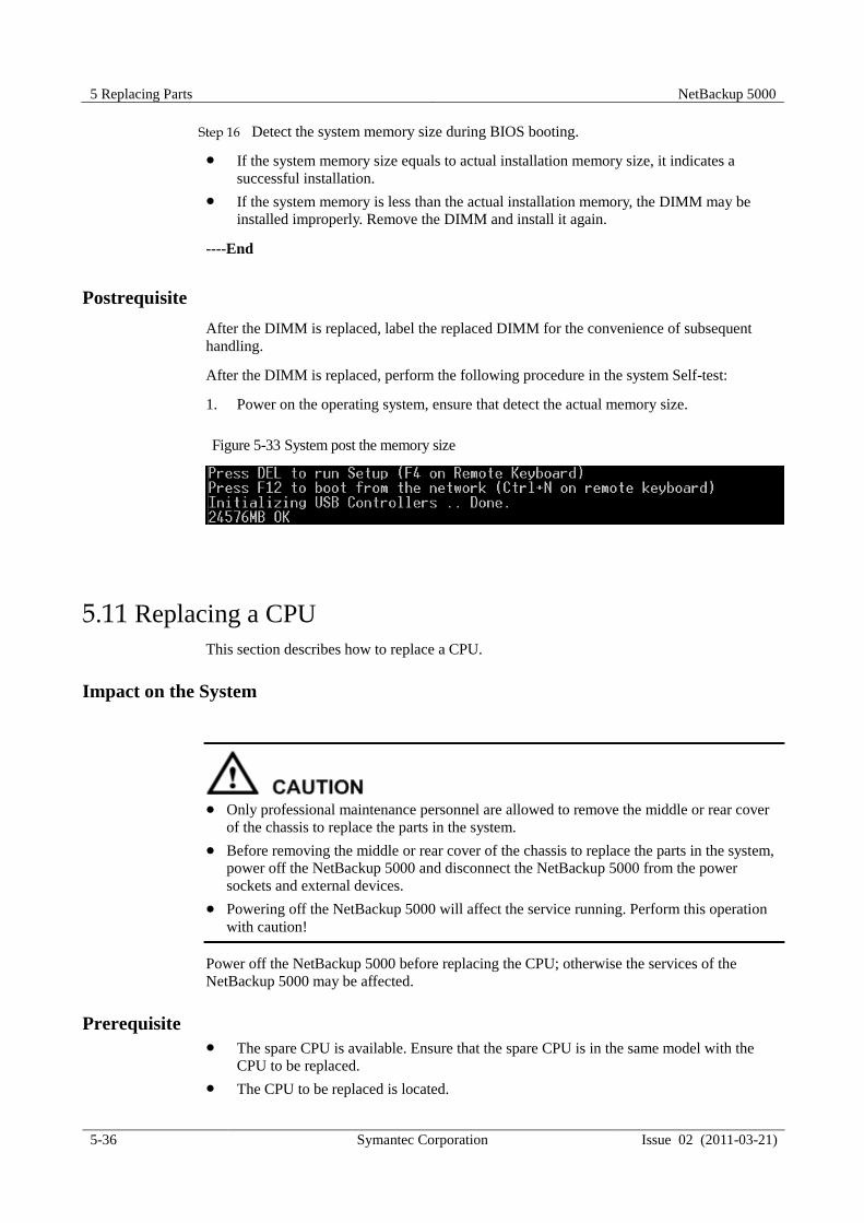
5 Replacing Parts NetBackup 5000
5-36 Symantec Corporation Issue 02 (2011-03-21)
Step 16 Detect the system memory size during BIOS booting.
If the system memory size equals to actual installation memory size, it indicates a
successful installation.
If the system memory is less than the actual installation memory, the DIMM may be
installed improperly. Remove the DIMM and install it again.
----End
Postrequisite
After the DIMM is replaced, label the replaced DIMM for the convenience of subsequent
handling.
After the DIMM is replaced, perform the following procedure in the system Self-test:
1. Power on the operating system, ensure that detect the actual memory size.
Figure 5-33 System post the memory size
5.11 Replacing a CPU
This section describes how to replace a CPU.
Impact on the System
Only professional maintenance personnel are allowed to remove the middle or rear cover
of the chassis to replace the parts in the system.
Before removing the middle or rear cover of the chassis to replace the parts in the system,
power off the NetBackup 5000 and disconnect the NetBackup 5000 from the power
sockets and external devices.
Powering off the NetBackup 5000 will affect the service running. Perform this operation
with caution!
Power off the NetBackup 5000 before replacing the CPU; otherwise the services of the
NetBackup 5000 may be affected.
Prerequisite
The spare CPU is available. Ensure that the spare CPU is in the same model with the
CPU to be replaced.
The CPU to be replaced is located.

NetBackup 5000 5 Replacing Parts
Issue 02 (2011-03-21) Symantec Corporation 5-37
Before replacing the CPU, power off the NetBackup 5000 and disconnect the NetBackup
5000 from the power sockets and external devices.
Tools and Materials
Philips screwdriver
ESD-preventive wrist strap
ESD-preventive clothes
ESD-preventive bag
Tag
Precaution
The NetBackup 5000 is supported by two power supplies. Cut off both of the power
supplies when powering off the NetBackup 5000.
Do not pry the CPU cooling fin during operation; otherwise the CPU and the cooling fin
will be damaged.
When replacing the CPU, wear only an ESD-preventive wrist strap, because wearing
ESD-preventive gloves may deform the CPU pin.
Procedure
Step 1 Wear ESD-preventive clothes and ESD-preventive wrist strap. For details on how to
wear the ESD-preventive wrist strap, see Wearing the ESD-Preventive Wrist Strap in
5.3 “Replacing a Disk Module”.
Step 2 Power off the NetBackup 5000 and disconnect the NetBackup 5000 from the power
sockets and external devices.
Step 3 Smoothly pull the NetBackup 5000 out of the cabinet, and lay the NetBackup 5000 on
a grounded and ESD-free operating platform. For details, see Step 3 in 5.4 “Replacing
a Fan Module”.
Step 4 Open the rear cover of the chassis. For details, see Step 4 in 5.6 “Replacing a Mini
SAS Cable”.
Step 5 Remove the wind cover above the CPU cooling fin. For details, see Step 5 in 5.10
“Replacing a DIMM”.
Step 6 Removing the CPU cooling fin.
1. Loosen the four captive screws on the CPU cooling fin counterclockwise, as shown in
step (1) in Figure 5-34.
2. Remove the CPU cooling fin, as shown in step (2) in Figure 5-34.

5 Replacing Parts NetBackup 5000
5-38 Symantec Corporation Issue 02 (2011-03-21)
Figure 5-34 Removing a CPU cooling fin
Step 7 Press the buckle over the CPU to spring up the buckle automatically.
Step 8 Slowly remove the CPU vertically upward.
Step 9 Place the removed CPU into the ESD-preventive bag. The operation of removing the
CPU is complete.
Step 10 Take the CPU to be installed out of the ESD-preventive bag.
Step 11 Press the buckle at the bottom of the CPU to spring up the buckle automatically.
Step 12 Aim the triangular symbol on the CPU at the triangular symbol on the bottom of the
CPU and insert the CPU vertically.
Step 13 Install the CPU cooling fin, as shown in step (1) and step (2) in Figure 5-35.
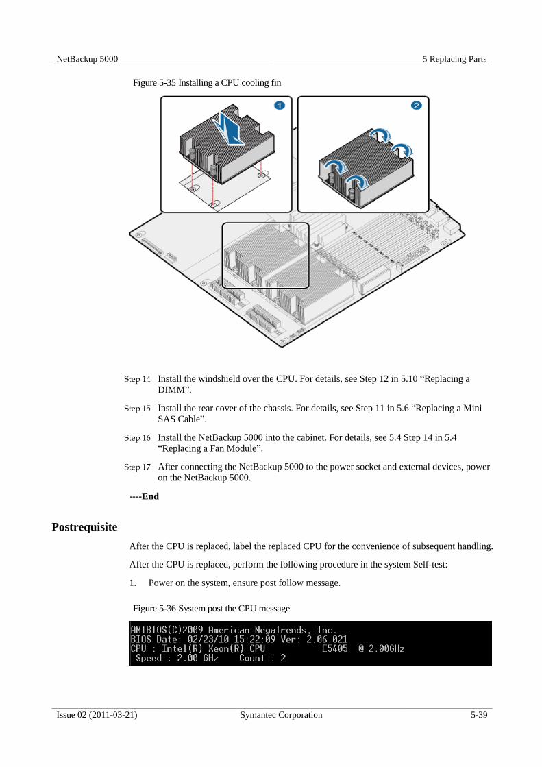
NetBackup 5000 5 Replacing Parts
Issue 02 (2011-03-21) Symantec Corporation 5-39
Figure 5-35 Installing a CPU cooling fin
Step 14 Install the windshield over the CPU. For details, see Step 12 in 5.10 “Replacing a
DIMM”.
Step 15 Install the rear cover of the chassis. For details, see Step 11 in 5.6 “Replacing a Mini
SAS Cable”.
Step 16 Install the NetBackup 5000 into the cabinet. For details, see 5.4 Step 14 in 5.4
“Replacing a Fan Module”.
Step 17 After connecting the NetBackup 5000 to the power socket and external devices, power
on the NetBackup 5000.
----End
Postrequisite
After the CPU is replaced, label the replaced CPU for the convenience of subsequent handling.
After the CPU is replaced, perform the following procedure in the system Self-test:
1. Power on the system, ensure post follow message.
Figure 5-36 System post the CPU message
5 Replacing Parts NetBackup 5000
5-40 Symantec Corporation Issue 02 (2011-03-21)
5.12 Replacing chassis
This section describes how to replace chassis.
Impact on the System
Only professional maintenance personnel are allowed to remove the middle or rear cover
of the chassis to replace the parts in the system.
Before removing the middle or rear cover of the chassis to replace the parts in the system,
power off the NetBackup 5000 and disconnect the NetBackup 5000 from the power
sockets and external devices.
Powering off the NetBackup 5000 will affect the service running. Perform this operation
with caution!
Power off the NetBackup 5000 before replacing the chassis; otherwise, the services of the
NetBackup 5000 may be affected.
Prerequisite
The chassis for replacing is available
The chassis to be replaced is located.
Record the original IPMI IP address of the chassis to be replaced
Step 1 Connect the NetBackup 5000 cabinet to the KVM.
Step 2 Press the Power button on the rear of the cabinet to power on the NetBackup 5000
Step 3 On the system self-check page, the IPMI IP address is displayed, as shown in Figure
5-37.
In this section, the following procedures use the IPMI IP address: 192.168.0.10 as an example.

NetBackup 5000 5 Replacing Parts
Issue 02 (2011-03-21) Symantec Corporation 5-41
Figure 5-37 IPMI IP address displayed on the system self-check Page
Step 4 Record the IP Address, Subnet Mask and GateWay.
Before replacing the chassis, power off the NetBackup 5000 and disconnect it from the
power sockets and external devices.
Tools and Materials
Philips screwdriver
ESD-preventive gloves
ESD-preventive wrist strap
ESD-preventive clothes
ESD-preventive bag
Tag
PC client (Windows)
Switch
IPMITOOL software
Precaution
The NetBackup 5000 is supported by two power supplies. Cut off both of the power
supplies when powering off the NetBackup 5000.
Do not pry the CPU cooling fin during operation; otherwise the CPU and the cooling fin
will be damaged.

5 Replacing Parts NetBackup 5000
5-42 Symantec Corporation Issue 02 (2011-03-21)
Procedure
Step 1 Wear the ESD-preventive clothes, ESD-preventive wrist strap, and ESD-preventive
gloves. For details on how to wear the ESD-preventive wrist strap, see Wearing the
ESD-Preventive Wrist Strap in 5.3 “Replacing a Disk Module”.
Step 2 Power off the NetBackup 5000 and disconnect the NetBackup 5000 from the power
sockets and external devices.
Step 3 Smoothly pull the NetBackup 5000 out of the cabinet, and lay the NetBackup 5000 on
a grounded and ESD-free operating platform. For details, see Step 3 in 5.4 “Replacing
a Fan Module”.
Step 4 Remove the disk modules. For details, see Step 2 to Step 4 in 5.3 “Replacing a Disk
Module”.
Step 5 Open the rear cover of the chassis. For details, see Step 4 in 5.6 “Replacing a Mini
SAS Cable”.
Step 6 Remove the wind cover over the CPU cooling fin. For details, see Step 5 in 5.10
“Replacing a DIMM”.
Step 7 Remove the DIMMs. For details, see Step 6 to Step 7 in 5.10 “Replacing a DIMM”.
Step 8 Remove the CPU and cooling fin. For details, see Step 6 to Step 8 in 5.11 “Replacing
a CPU”.
Step 9 Remove the RAID card. For details, see Step 5 to Step 6 in 5.7 “Replacing a RAID
Card”.
Step 10 Remove the NIC. For details, see Step 5 and Step 6 in 5.9 “Replacing a NIC”.
Step 11 Move the new NetBackup 5000 chassis on the operating platform.
Step 12 Install the RAID card. For details, see Step 12 to Step 14 in 5.7 “Replacing a RAID
Card”.
Step 13 Install the NIC. For details, see Step 8 to Step 10 in 5.9 “Replacing a NIC”.
Step 14 Connect the internal cables of the main board. For details, see the instructions on the
back of the rear cover of the NetBackup 5000 chassis.
Step 15 Install the CPU and cooling fin. For details, see Step 11 to Step 13 in 5.11 “Replacing
a CPU”.
Step 16 Install the DIMMs. For details, see Step 10 to Step 11 in 5.10 “Replacing a DIMM”.
Step 17 Install the windshield over the CPU. For details, see Step 12 in 5.10 “Replacing a
DIMM”.
Step 18 Install the rear cover of the chassis. For details, see Step 11 in 5.6 “Replacing a Mini
SAS Cable”.
Step 19 Install the disk modules. For details, see Step 7 to Step 8 in 5.3 Replacing a Disk
Module.
Step 20 Install the new NetBackup 5000 into the cabinet. For details, see Step 14 in 5.4
“Replacing a Fan Module”.
Step 21 Connecting the NetBackup 5000 to the power socket and the KVM.
Step 22 Press the Power button on the rear of the cabinet to power on the NetBackup 5000.

NetBackup 5000 5 Replacing Parts
Issue 02 (2011-03-21) Symantec Corporation 5-43
----End
Postrequisite
After the chassis is replaced, label the replaced chassis for the convenience of subsequent
handling.
After the chassis is replaced, perform the following procedure to set the time zone and date:
1. Connect the KVM on device, ensure CPU, memory and RAID card message is correct in
system self-test post;
2. Login with credentials: root/root.
3. Type yast at the command prompt to start the YaST control center.
Figure 5-38 YaST control center
4. Use the arrow keys to locate System and Date and Time, and then press Enter.

5 Replacing Parts NetBackup 5000
5-44 Symantec Corporation Issue 02 (2011-03-21)
Figure 5-39 Selecting Date and Time
5. On the Clock and Time Zone interface, Under Time and Date, select Change „, and
then press Enter.
Figure 5-40 Setting the time zone
6. In the Change System Date and Time interface, set the date and time as required, click
Apply, and then press Enter.

NetBackup 5000 5 Replacing Parts
Issue 02 (2011-03-21) Symantec Corporation 5-45
Figure 5-41 Setting the date and time
7. In the Clock and Time Zone interface, select Accept, and then press Enter.
Figure 5-42 Confirming the changes
8. Quit the YaST control center.
9. Type the following commands to setup IPMI time:
service ipmi start
ipmitool sel time set "mm/dd/yyyy hh:mm:ss"
10. Type yast at the command prompt to start the YaST control center.
11. Select Network Devices, and select Network Card.

5 Replacing Parts NetBackup 5000
5-46 Symantec Corporation Issue 02 (2011-03-21)
Figure 5-43 Config network card
12. Select the network card which have been replaced, select Edit to go on.
Figure 5-44 Select network card
13. Input the IP address and Subnet Mask field, select Next to finish configuration.

NetBackup 5000 5 Replacing Parts
Issue 02 (2011-03-21) Symantec Corporation 5-47
Figure 5-45 Edit network card IP address
14. Select Quit.
15. Run the reboot command to reboot the NetBackup 5000.
----End


NetBackup 5000 6 Case Collections
Issue 02 (2011-03-21) Symantec Corporation 6-1
6 Case Collections
About This Chapter
This chapter describes the case collections of the NetBackup 5000.
6.1 No Self-Check Interface of the RAID Card Is Displayed During the Self-Check Process of
the NetBackup 5000
This section describes how to handle the situation that no self-check interface of the RAID
card is displayed during the self-check process of the NetBackup 5000.
6.2 After the Device Is Powered On and MegaRAID Is Prompted, “F/W Initializing device
0%” Is Displayed During the Self-Check Process of the RAID Card
This section describes how to handle the situation that after the device is powered on and
MegaRAID is prompted, F/W Initializing device 0% is displayed during the self-check
process of the RAID card.
6.3 When the NetBackup 5000 Starts, the RAID Card Cannot Pass the Self-Check
This section describes how to handle the situation that the RAID card cannot pass the self-
check.
6.4 Slot Numbers of Hard Disks Are in Disorder
This section describes how to handle the situation that the slot numbers of hard disks are in
disorder.
6.5 After the NetBackup 5000 Starts, “Invalid SAS topology detected” Is Displayed and
the System Cannot Be Accessed
This section describes how to handle the situation that after the NetBackup 5000 starts,
“Invalid SAS topology detected" is displayed and the system cannot be accessed.
Error! Reference source not found.Error! Reference source not found.
This section describes how to handle the situation that the battery information of the
NetBackup 5000 cannot be displayed on the monitor interface.
6.6 The Service Network of the NetBackup 5000 Is Blocked
This section describes how to handle the situation that the service network of the NetBackup
5000 is blocked.

6 Case Collections NetBackup 5000
6-2 Symantec Corporation Issue 02 (2011-03-21)
6.7 The ISM Interface Cannot Be Logged In To
This section describes how to handle the situation that the ISM interface cannot be logged in
to.
6.8 The IPMITOOL Fails to Connect the IPMI Port
This section describes how to handle the situation that the IPMITOOL fails to connect the
IPMI port.
6.9 After a Faulty Disk Is Replaced, the Alarm Persists
This section describes how to handle the situation that after a faulty disk is replaced, the alarm
persists.
6.9 The System Cannot Start and the Screen Is Black
This section describes how to handle the situation that the system cannot start and the screen
is black.
6.11 The Online Status Indicator of the Hard Disk Is Off
This section describes how to handle the situation that the online status indicator of the hard
disk is off.
6.12 Running the Install.VRTSat.sh Script Fails
This section describes how to handle the situation that running Install.VRTSat.sh script fails.
6.1 No Self-Check Interface of the RAID Card Is Displayed During the Self-Check Process of the NetBackup 5000
This section describes how to handle the situation that no self-check interface of the RAID
card is displayed during the self-check process of the NetBackup 5000.
Case Source
This case is obtained from the device test in the equipment room.
Description
No self-check interface of the RAID card is displayed during the self-check process of the
NetBackup 5000.
Diagnosis Procedure
1. Reinsert the SAS cable that connects the RAID card and the expansion board and ensure
that the connection is proper.
2. Reinsert the RAID card and ensure that the RAID card is installed properly.
3. Power on the NetBackup 5000 again and perform the self-check.
Fault Location
If the problem persists after you follow the previous steps, the RAID card is damaged.

NetBackup 5000 6 Case Collections
Issue 02 (2011-03-21) Symantec Corporation 6-3
Troubleshooting Method
1. Replace the RAID card. For details, see 5.7 Replacing a RAID Card.
2. If the problem persists after you replace the RAID card, contact technical support
engineers.
----End
6.2 After the Device Is Powered On and MegaRAID Is
Prompted, “F/W Initializing device 0%” Is Displayed During the Self-Check Process of the RAID Card
This section describes how to handle the situation that after the device is powered on and
MegaRAID is prompted, "F/W Initializing device 0%” is displayed during the self-check
process of the RAID card.
Case Source
This case is obtained from the device test in the equipment room.
Description
After the device is powered on and MegaRAID is prompted, “F/W Initializing device 0%”
is displayed during the self-check process of the RAID card and the interface is stuck.
Diagnosis Procedure
1. Reinsert the SAS cable that connects the RAID card and the expansion board and ensure
that the connection is proper.
2. Reinsert the RAID card and ensure that the RAID card is installed properly.
3. Power on the NetBackup 5000 again and perform the self-check.
Fault Location
If the problem persists after you follow the previous steps, the RAID card is damaged.
Troubleshooting Method
Replace the RAID card. For details, see 5.6 “Replacing a RAID Card” If the problem
persists after you replace the RAID card, contact technical support engineers.
----End
6.3 When the NetBackup 5000 Starts, the RAID Card Cannot Pass the Self-Check
This section describes how to handle the situation that the RAID card cannot pass the self-
check.

6 Case Collections NetBackup 5000
6-4 Symantec Corporation Issue 02 (2011-03-21)
Case Source
This case is obtained from the device test in the equipment room.
Description
When the NetBackup 5000 starts, “F/W initializing device 100%” is displayed during the
self process of the LSI 8708EM2 RAID card. Then, the interface is stuck and the system
cannot start.
Diagnosis Procedure
1. Check whether there are faulty hard disks in the NetBackup 5000 slots. If there are,
replace the faulty ones. For details, see 5.3 Replacing a Disk Module.
2. Shut down and power off the NetBackup 5000, and then open the chassis cover to check
whether the cables are connected properly. If they are not, connect them again. (Note:
Port A and port B on the expansion board should be respectively connected to the ports
that are signed as PORTS 3-0 and PORTS 7-4 on the LSI8708EM2 RAID card, as
shown in Figure 6-1.)
Figure 6-1 Checking the mini SAS cables

NetBackup 5000 6 Case Collections
Issue 02 (2011-03-21) Symantec Corporation 6-5
Fault Location
If the problem persists after you follow the previous steps, the mini SAS cables are damaged.
Troubleshooting Method
Replace the mini SAS cables. For details, see 5.6 “Replacing a RAID Card”. If the
problem persists after you replace the mini SAS cables, contact technical support engineers.
----End
6.4 Slot Numbers of Hard Disks Are in Disorder
This section describes how to handle the situation that the slot numbers of hard disks are in
disorder.
Case Source
This case is obtained from the device test in the equipment room.
Description
When this fault appears, the RAID group is degraded and the hard disk settings cannot be
found in the RAID card logs. The slot numbers of the NetBackup 5000 range from 0 to 23.
When the RAID card is faulty, the slot numbers of the hard disks exceed this range or cannot
correspond to the hard disks.
Diagnosis Procedure
Enter the MSM or WebBios of the RAID card to check whether the hard disks are correctly
identified, slot numbers range from 0 to 23, and slot numbers correspond to the actual slots.
Fault Location
If the problem persists after you follow the previous steps, the RAID card is damaged.
Troubleshooting Method
Replace the RAID card. For details, see 5.6 “Replacing a RAID Card”. If the problem
persists after you replace the RAID card, contact technical support engineers.
----End
6.5 After the NetBackup 5000 Starts, “Invalid SAS
topology detected” Is Displayed and the System Cannot Be Accessed
This section describes how to handle the situation that after the NetBackup 5000 starts,
“Invalid SAS topology detected” is displayed and the system cannot be accessed.

6 Case Collections NetBackup 5000
6-6 Symantec Corporation Issue 02 (2011-03-21)
Case Source
This case is obtained from the device test in the equipment room.
Description
After the NetBackup 5000 starts and the following is displayed, the interface is stuck and the
system cannot be accessed.
“Invalid SAS topology detected, please check your cable configurations, repair the problem,
and restart your system”
Diagnosis Procedure
Reinsert the two mini SAS cables. For details, see “5.6 Replacing a RAID card”.
Reinsert the two mini SAS cables into the correct position.
Before removing or inserting the mini SAS cables, nip the pins of the plugs.
Fault Location
If the problem persists after you follow the previous steps, the mini SAS cables are damaged.
Troubleshooting Method
Replace the mini SAS cables. For details, see 5.6 “Replacing a RAID Card”. If the
problem persists after you replace the mini SAS cables, contact technical support engineers.
----End
6.6 The Service Network of the NetBackup 5000 Is Blocked
This section describes how to handle the situation that the service network of the NetBackup
5000 is blocked.
Case Source
This case is obtained from the device test in the equipment room.
Description
The service network of the NetBackup 5000 is blocked.
Diagnosis Procedure
1. Check whether the external network to which the switch, network cable, and application
server (AS) connect is normal.
2. Check whether the link indicator of the network port is on. If the link indicator is off,
reinsert the network cable to see whether the link indicator is on. Repeat this operation
for several times.

NetBackup 5000 6 Case Collections
Issue 02 (2011-03-21) Symantec Corporation 6-7
Fault Location
If the problem persists after you follow the previous steps, the network interface card (NIC) is
damaged.
Troubleshooting Method
Replace the NIC. For details, see 5.7 “Replacing a NIC”. If the problem persists after you
replace the NIC, contact technical support engineers.
----End
6.7 The ISM Interface Cannot Be Logged In To
This section describes how to handle the situation that the ISM interface cannot be logged in
to.
Case Source
This case is obtained from the device test in the equipment room.
Description
After you enter the IP address of the NetBackup 5000 management network port in the
address bar of the IE browser, the interface has no response and the ISM cannot be logged in
to.
Diagnosis Procedure
1. Run the ping IPMI-IP command to check whether the network can be pinged through.
2. Check whether the IP addresses of the PC and the management network port for the
NetBackup 5000 are in the same network segment. If they are not, add a route.
In the PC, enter route add subnet mask subnet mask gateway.
In the NetBackup 5000, enter route add-net subnet netmask subnet mask gw gateway.
3. Ensure that the BMC does not restart.
Fault Location
If the problem persists after you follow the previous steps, contact technical support engineers.
Troubleshooting Method
Handle this problem according to the diagnosis procedure.
----End
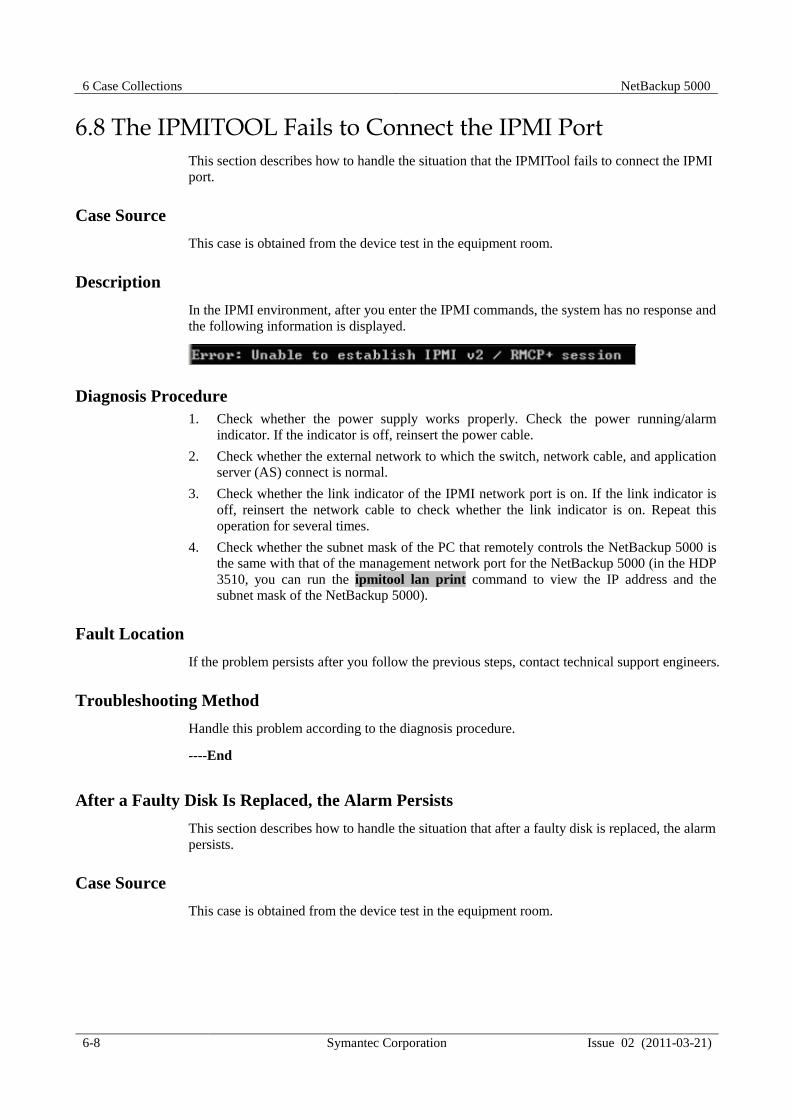
6 Case Collections NetBackup 5000
6-8 Symantec Corporation Issue 02 (2011-03-21)
6.8 The IPMITOOL Fails to Connect the IPMI Port This section describes how to handle the situation that the IPMITool fails to connect the IPMI
port.
Case Source
This case is obtained from the device test in the equipment room.
Description
In the IPMI environment, after you enter the IPMI commands, the system has no response and
the following information is displayed.
Diagnosis Procedure
1. Check whether the power supply works properly. Check the power running/alarm
indicator. If the indicator is off, reinsert the power cable.
2. Check whether the external network to which the switch, network cable, and application
server (AS) connect is normal.
3. Check whether the link indicator of the IPMI network port is on. If the link indicator is
off, reinsert the network cable to check whether the link indicator is on. Repeat this
operation for several times.
4. Check whether the subnet mask of the PC that remotely controls the NetBackup 5000 is
the same with that of the management network port for the NetBackup 5000 (in the HDP
3510, you can run the ipmitool lan print command to view the IP address and the
subnet mask of the NetBackup 5000).
Fault Location
If the problem persists after you follow the previous steps, contact technical support engineers.
Troubleshooting Method
Handle this problem according to the diagnosis procedure.
----End
After a Faulty Disk Is Replaced, the Alarm Persists
This section describes how to handle the situation that after a faulty disk is replaced, the alarm
persists.
Case Source
This case is obtained from the device test in the equipment room.

NetBackup 5000 6 Case Collections
Issue 02 (2011-03-21) Symantec Corporation 6-9
Description
During the normal running of the NetBackup 5000, the online indicator of the new hard disk
is still red on after you replace the faulty hard disk whose online indicator is red on.
Meanwhile, you cannot query the new hard disk on the system monitor interface.
Diagnosis Procedure
1. Run the upgrade.bat <IPMI ip> command, select the number button 4, and then enter
the password t3000diag. The following interface is displayed.
Figure 6-2 Debugging serial port interface of the expansion board
2. Run the porte <log_phyid> command to force the hard disk out of the self-protective
mode. (Note: log_phyid indicates the logical slot number. From left to right and from
top to bottom, the upper left slot is slot 0 and the lower right slot is slot 23.)
3. If the online status indicator of the new hard disk is green on, the fault is removed.
Fault Location
If the problem persists after you follow the previous steps, contact technical support engineers.
Troubleshooting Method
Handle this problem according to the diagnosis procedure.
----End
6.9 After a Faulty Disk Is Replaced, the Alarm Persists
Case Source
This section describes how to handle the situation that after a faulty disk is replaced, the alarm
persists.

6 Case Collections NetBackup 5000
6-10 Symantec Corporation Issue 02 (2011-03-21)
Description
During the normal running of the NetBackup 5000, the online indicator of the new hard disk
is still red on after you replace the faulty hard disk whose online indicator is red on.
Meanwhile, you cannot query the new hard disk on the system monitor interface
Diagnosis Procedure
1. Run the upgrade.bat <IPMI ip> command, select the number button 4, and then enter
the password t3000diag. The following interface is displayed.
Figure 6-3 Debugging serial port interface of the expansion board
2. Run the porte <log_phyid> command to force the hard disk out of the self-protective
mode. (Note: log_phyid indicates the logical slot numbers. From left to right and from
top to bottom, the upper left slot is slot 0 and the lower right slot is slot 23.
3. If the online indicator of the new hard disk is green on, the fault is removed.
Fault Location
If the problem persists after you follow the previous steps, contact technical support engineers.
Troubleshooting Method
Handle this problem according to the diagnosis procedure.
----End
6.10 The System Cannot Start and the Screen Is Black This section describes how to handle the situation that the system cannot start and the screen
is black.
Case Source
This case is obtained from the device test in the equipment room.

NetBackup 5000 6 Case Collections
Issue 02 (2011-03-21) Symantec Corporation 6-11
Description
The system cannot start and the screen is black.
Diagnosis Procedure
1. View 80 port LED. As shown in Figure 6-3, 80 port LED consists of eight LEDs,
indicating a 8-bit binary numeral. LED on indicates 1 and LED off indicates 0. The
LEDs near the board verge indicate high bit; the LEDs near the fan LED is low bit.
Figure 6-4 80 port
2. Covert the binary numeral to a hexadecimal numeral. According to Table 6-1 to find the
fault cause and remove the fault.
Table 6-1 Corresponding relationship between the fault code and the fault cause
Fault Code Fault Cause Corresponding Measure
00, D0 to D2 The CPU is inserted
improperly.
The CPU is faulty.
The socket of the CPU is
faulty.
Reinsert the CUP.
Replace the CPU.
Replace the
mainboard/chassis.
E6 The memory bar is inserted
improperly. Reinsert the memory bar.
E1, E* (starting with
E)
The memory bar is inserted
improperly.
The memory bar is inserted
into the wrong socket.
The socket of the memory bar
is faulty.
Reinsert the memory bar.
Insert the memory bar into
the right socket.
Replace the
mainboard/chassis.
AA The BIOS is not normal. The
BIOS may not be successfully
upgraded (which is caused
Refer to the Upgrade Guide to
upgrade the BIOS again.

6 Case Collections NetBackup 5000
6-12 Symantec Corporation Issue 02 (2011-03-21)
Fault Code Fault Cause Corresponding Measure
during the process of upgrading
the BIOS files).
Fault Location
If the problem persists after you follow the previous steps, contact technical support engineers.
Troubleshooting Method
Handle this problem according to the diagnosis procedure.
----End
6.11 The Online Status Indicator of the Hard Disk Is Off This section describes how to handle the situation that the online status indicator of the hard
disk is off.
Case Source
This case is obtained from the device test in the equipment room.
Description
The online status indicator of the hard disk is off.
Diagnosis Procedure
Check whether hard disks are inserted properly.
Fault Location
If the problem persists after you follow the previous steps, the online status indicator of the
hard disk is faulty.
Troubleshooting Method
Replace the chassis of the NetBackup 5000. If the problem persists after you replace the
chassis of the NetBackup 5000, contact technical support engineers.
----End
6.12 Running the Install.VRTSat.sh Script Fails
This section describes how to handle the situation that running the Install.VRTSat.sh script
fails.

NetBackup 5000 6 Case Collections
Issue 02 (2011-03-21) Symantec Corporation 6-13
Case Source
This case is obtained from the device test in the equipment room.
Description
When you initialize the system in FQDN mode, the following error is displayed on the
Network Reconfiguration interface.
Figure 6-5 Failing to run the Install.VRTSat.sh script
Diagnosis Procedure
During the start of Apache2 server, it queries the DNS to perform a reverse analysis, that is,
sending a request of resolving the IP address to a host name and querying this request on the
DNS. If the DNS does not respond to this request immediately (neither a positive response or
a negative one), that is, there is no response displayed on the Linux terminal, the response
times out, which leads to the failed start of the apache2 server. Ultimately, running the Install.
VRTSat.sh script fails.
Fault Location
The DNS does not provide reverse analysis.

6 Case Collections NetBackup 5000
6-14 Symantec Corporation Issue 02 (2011-03-21)
Troubleshooting Method
1. Create a reverse analysis on the DNS and then enter the Storage pool configuration
wizard interface. If the faulty persists, proceed to the next step.
2. Modify the /etc/resolv.conf configuration file and add the following “ options
timeout :1 attempts :1”.
----End
6.13 WebBIOS Interface Can Not Enter This section describes how to handle the situation that WebBIOS interface can not enter.
Case Source
This case is obtained from the device test in the equipment room.
Symptom
After the self-check of RAID card, two Virtual Drivers were detected. Press Ctrl + H, while
WebBIOS interface can not enter.
Figure 6-6 Press Ctrl + H to enter WebBIOS interface
Procedure
Step 1 Connect the NetBackup 5000 to the KVM.
Step 2 Reboot the operating system of NetBackup 5000.
Step 3 During the system self-check, press Del to enter the BIOS interface, as shown in Figure 6-7.

NetBackup 5000 6 Case Collections
Issue 02 (2011-03-21) Symantec Corporation 6-15
Figure 6-7 Press Del to enter BIOS interface
Step 4 On the BIOS interface, choose the IPMIBoot tab, as shown in Figure 6-8.
Figure 6-8 Choose Boot Settings Configuration
Step 5 On the IPMIBoot tab page, Press enter on the Boot Settings configuration, as shown in
Figure 6-8.

6 Case Collections NetBackup 5000
6-16 Symantec Corporation Issue 02 (2011-03-21)
Step 6 On the Boot Settings configuration tab page, use arrow keys to choose Interrupt 19
Capture to be Enabled, as shown in Figure 6-9.
Figure 6-9 Choose Interrup 19 Capture
Step 7 Press F10 to Save configuration changes and exit setup, and press Enter, as shown in
Figure 6-10.
Figure 6-10 Press Del to enter BIOS interface
The WebBIOS interface will be entered normally.

NetBackup 5000 7 Related Operations
Issue 02 (2011-03-21) Symantec Corporation 7-1
7 Related Operations
About This Chapter This section describes the related operations during the troubleshooting process.
7.1 Logging In to the System Monitoring Interface
This section describes how to log in to the NetBackup 5000 system monitoring interface.
7.2 Collecting Log Information
This section describes how to collecting log information.
7.1 Logging In to the System Monitoring Interface
This section describes how to log in to the NetBackup 5000 system monitoring interface.
Prerequisite
The IP address of the Windows PC to log in to the NetBackup 5000 should be in the same
network segment as that of the NetBackup 5000.
Procedure
Step 1 Open the IE browser on the Windows PC. Enter http://IP address in the address bar (the IP
address is the IP address of the service network port of theNetBackup 5000). Press Enter and
the login interface is displayed.
Set the security level if any when you log in to the PD Manange through the Internet Explorer according
to the tips.

7 Related Operations NetBackup 5000
7-2 Symantec Corporation Issue 02 (2011-03-21)
Figure 7-1 Login Interface
Step 2 Enter the user name and password respectively in the User Name and Password text boxes.
The default user name and password are respectively root and root.
Step 3 Click Log on and the main interface of the NetBackup 5000 is displayed.
Figure 7-2 Main interface of the NetBackup 5000
Step 4 Choose Monitor > System and enter the system monitoring interface.

NetBackup 5000 7 Related Operations
Issue 02 (2011-03-21) Symantec Corporation 7-3
Figure 7-3 System monitoring interface
Step 5 In the navigation tree, unfold the IP address node and check the hardware status.
----End
7.2 Collecting Log Information
This section describes how to collecting log information.
Prerequisite
Collecting log information requires login NetBackup 5000 by ssh client with root user.
Procedure
Collect the log information of PD software.
1. /opt/pdconfigure/scripts/support/PDgetlogs.sh
Collect the log of T3500
2. mkdir /var/log/NetBackup5000
3. ipmitool sel elist > /var/log/NetBackup5000/sel.log
4. ipmitool sdr elist > /var/log/NetBackup5000/sdr.log
Collect the log of MSM.
5. /opt/MegaRAID/MegaCli/MegaCli64 -adpeventlog – GetEvents -f
/var/log/NetBackup5000/RAIDCard.log -a0
6. /opt/MegaRAID/MegaCli/MegaCli64 -fwtermlog dsply -a0 >
/var/log/NetBackup5000/RAIDCardFw.log
----End

NetBackup 5000 8 Monitoring from System Interface
Issue 02 (2011-03-21) Symantec Corporation 8-1
8 Monitoring from System Interface
About This Chapter
This section describes the maintenance items on the management software, including viewing
alarms and querying hardware state.
8.1 Checking the CPU State
This section describes how to check the CPU state on the system monitoring interface.
8.2 Viewing the Disk State
This section describes how to check the disk state on the system monitoring interface.
8.3 Check the RAID Group State
This section describes how to check the RAID group state on the system monitoring interface.
8.4 Checking the Fan State
This section describes how to check the fan state on the system monitoring interface.
8.5 Checking the Power Supply State
This section describes how to check the power supply state on the system monitoring
interface.
Error! Reference source not found.Error! Reference source not found.
This section describes how to check the miscellaneous information on the system monitoring
interface.
8.6 Viewing Hardware Alarms
This section describes how to view hardware alarms on the system monitoring interface of the
management software.
8.1 Checking the CPU State This section describes how to check the CPU state on the system monitoring interface. By
checking the state of the CPU, you can know whether the CPU works normally.

8 Monitoring from System Interface NetBackup 5000
8-2 Symantec Corporation Issue 02 (2011-03-21)
If the CPU is in the Presence detected state, it indicates that the CPU runs normally.
Log in to the system monitoring interface. Expand the node in the navigation tree, and then
click CPU.
Figure 8-1 View CPU staus
ID-x indicates CPU x (the value of x is 1 or 2).
Table 8-1 Description of parameters related to the CPU state
Parameter Description
Status The state of the CPU.
Presence detected indicates that the CPU works normally.
Disabled indicates that the CPU is absent.
Voltage The voltage of the CPU.
8.2 Viewing the Disk State This section describes how to check the disk state on the system monitoring interface. By
checking the disk state, you can know whether the disk works normally.
The normal state of a system and data disk is Online.
The normal state of a hot spare disk is Hotspare.
Log in to the system monitoring interface.
Expand the node in the navigation tree, and then click Disk.

NetBackup 5000 8 Monitoring from System Interface
Issue 02 (2011-03-21) Symantec Corporation 8-3
Figure 8-2 View disk staus
Table 8-2 Description of parameters related to the disk state
Parameter Description
Slot Number The slot number of the disk.
NOTE
For details on the slot number of a disk, see "Panel" in the NetBackup 5000
Product Description.
Status The running state of the disk.
Online indicates that the disk is a member disk of a RAID group
and running normally.
Hotspare indicates that the disk is a hot spare disk.
Rebuild indicates that the disk is being reconstructed.
Unconfigured(good) indicates that the disk is not a member disk
of a RAID group and is running normally.
Capacity The disk capacity. Unit: GB.
Type The physical type of the disk. The type of disks in the NetBackup
5000 is SATA.
Enclosure ID The ID of the enclosure in which the disk is.
8.3 Check the RAID Group State This section describes how to check the RAID group state on the system monitoring interface.
By checking the RAID group state, you can know whether the RAID group works normally.
The normal state of a RAID Group is Optimal.

8 Monitoring from System Interface NetBackup 5000
8-4 Symantec Corporation Issue 02 (2011-03-21)
Log in to the system monitoring interface. Expand the node in the navigation tree, and then
click RAID.
Figure 8-3 View RAID staus
Table 8-3 Description of parameters related to the RAID group state
Parameter Description
Name The name of the RAID group.
Status A RAID group may be in the one of the following states:
Optimal indicates that the RAID group is normal.
Degraded indicates that the RAID group is degraded.
Capacity The capacity of the RAID group. Unit: GB.
Type The level of the RAID group.
The level of a RAID group that consists of data disks is RAID 6.
The level of a RAID group that consists of system disks is RAID
1.
Disks The disks included in the RAID group. The numbers displayed on
the interface are the slot numbers of the corresponding disks.

NetBackup 5000 8 Monitoring from System Interface
Issue 02 (2011-03-21) Symantec Corporation 8-5
8.4 Checking the Fan State This section describes how to check the fan state on the system monitoring interface. By
checking the fan state, you can know whether the fan works normally.
The normal state of a fan is Device Present.
Log in to the system monitoring interface. Expand the node in the navigation tree, and then
click Fan.
Figure 8-4 View FAN staus
ID-x indicates fan x (the value of x is an integer ranging from 1 to 6).
Table 8-4 Description of parameters related to the fan state
Parameter Description
Status The fan state.
Device Present indicates that the fan works normally.
Device Absent indicates that the fan works abnormally.
Speed The rotation speed of the fan.

8 Monitoring from System Interface NetBackup 5000
8-6 Symantec Corporation Issue 02 (2011-03-21)
8.5 Checking the Power Supply State This section describes how to check the power supply state on the system monitoring
interface. By checking the power supply state, you can know whether the power supply works
normally.
The normal state of a power supply is Presence detected.
Log in to the system monitoring interface. Expand the node in the navigation tree, and then
click Power Supply.
Figure 8-5 View Power Supply staus
Table 8-5 Description of parameters related to the power supply state
Parameter Description
Status The running state of the power supply.
Presence detected indicates that the power supply works
normally.
Failure detected indicates that the power supply is absent or
faulty.
Wattage The power value of the power supply. Unit: Watts.
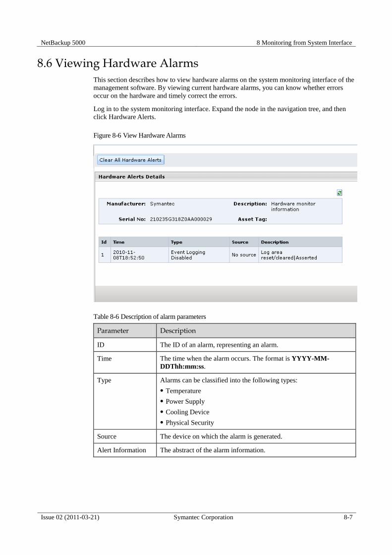
NetBackup 5000 8 Monitoring from System Interface
Issue 02 (2011-03-21) Symantec Corporation 8-7
8.6 Viewing Hardware Alarms This section describes how to view hardware alarms on the system monitoring interface of the
management software. By viewing current hardware alarms, you can know whether errors
occur on the hardware and timely correct the errors.
Log in to the system monitoring interface. Expand the node in the navigation tree, and then
click Hardware Alerts.
Figure 8-6 View Hardware Alarms
Table 8-6 Description of alarm parameters
Parameter Description
ID The ID of an alarm, representing an alarm.
Time The time when the alarm occurs. The format is YYYY-MM-
DDThh:mm:ss.
Type Alarms can be classified into the following types:
Temperature
Power Supply
Cooling Device
Physical Security
Source The device on which the alarm is generated.
Alert Information The abstract of the alarm information.

8 Monitoring from System Interface NetBackup 5000
8-8 Symantec Corporation Issue 02 (2011-03-21)
Table 8-7 Alarm information
Classification Type Device Description
Overtemperatur
e of the CPU
core
Temperature CPU Upper non-critical
going high
Overtemperatur
e of the air
intake of the
chassis
Temperature Air intake of the
chassis
Upper non-critical
going high
power supply
absence
Power supply Power device Failure detected
Fan module
absence
Cooling device Fan Device absent
Chassis
intrusion
Physical security Chassis General chassis
intrusion

NetBackup 5000 9 Monitoring from MSM
Issue 02 (2011-03-21) Symantec Corporation 9-1
9 Monitoring from MSM
About This Chapter
The MegaRAID Storage Manager software enables monitor the status of drives, virtual drives.
This chapter describes how to monitoring from MSM of the NetBackup 5000.
9.1 Monitoring MSM Events
This section describes how to monitoring MSM events.
9.2 Monitoring Controller
This section describes how to monitoring controller status.
9.3 Monitoring Drives
This section describes how to monitoring drives.
9.4 Monitoring Virtual Drives
This section describes how to monitoring virtual drives.
9.5 Monitoring Battery Backup Units
This section describes how to monitoring battery backup units.
9.6 Monitoring Rebuilds and Other Processes
This section describes how to monitoring rebuild and other processes.
9.7 Events and Messages
This section describes MSM events and messages.
9.1 Monitoring MSM Events This section describes how to monitoring MSM events.
MegaRAID Storage Manager software monitors the activity and performance of controller
and the drives. When an event occurs (such as the creation of a new virtual drive or the
removal of a drive) an event message appears in the log displayed at the bottom of the
MegaRAID Storage Manager window.

9 Monitoring from MSM NetBackup 5000
9-2 Symantec Corporation Issue 02 (2011-03-21)
Figure 9-1 Event Information Window
Each message that appears in the event log has a severity level that indicates the importance
of the event, a date and timestamp, and a brief description. Click an event to display the same
information in a window.
Table 9-1 MSM Event Severity Levels
Severity Level Meaning
Information Informational message. No user action is necessary.
Warning Some component might be close to a failure point.
Critical A component has failed, but the system has not lost data.
Fatal A component has failed, and data loss has occurred or will occur.
9.2 Monitoring Controller This section describes how to monitoring controller status.
When MegaRAID Storage Manager software is running, you can see the status of controller
in the left panel of the MegaRAID Storage Manager window. If the controller is operating
normally, the controller icon looks like this: . If the controller has failed, a small red circle
appears to the right of the icon.
To display complete controller information, click controller icon in the left panel of the
MegaRAID Storage Manager window, and click the Properties tab in the right panel.

NetBackup 5000 9 Monitoring from MSM
Issue 02 (2011-03-21) Symantec Corporation 9-3
Figure 9-2 Shows the Controller Information
The Rebuild Rate, Patrol Read Rate, Reconstruction Rate, Consistency Check Rate, and BGI
Rate (background initialization) are all user selectable.
The BBU Present field indicates whether a battery backup unit is installed.
The Alarm Present and Alarm Enabled fields indicate whether the controller has an alarm to
alert the user with an audible tone when there is an error or problem on the controller. There
are options on the controller Properties tab for silencing or disabling the alarm.
9.3 Monitoring Drives This section describes how to monitoring drives.
When MegaRAID Storage Manager software is running, you can see the status of all drives in
the left panel of the MegaRAID Storage Manager window. If the drive is operating normally,
its icon looks like this: . If the drive has failed, a small red circle appears to the right of the
icon, like this: .
To display complete drive information, click a drive icon in the left panel of the MegaRAID
Storage Manager window, and click the Properties tab in the right panel.
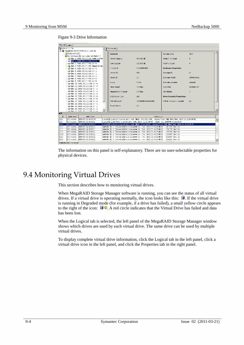
9 Monitoring from MSM NetBackup 5000
9-4 Symantec Corporation Issue 02 (2011-03-21)
Figure 9-3 Drive Information
The information on this panel is self-explanatory. There are no user-selectable properties for
physical devices.
9.4 Monitoring Virtual Drives This section describes how to monitoring virtual drives.
When MegaRAID Storage Manager software is running, you can see the status of all virtual
drives. If a virtual drive is operating normally, the icon looks like this: . If the virtual drive
is running in Degraded mode (for example, if a drive has failed), a small yellow circle appears
to the right of the icon: . A red circle indicates that the Virtual Drive has failed and data
has been lost.
When the Logical tab is selected, the left panel of the MegaRAID Storage Manager window
shows which drives are used by each virtual drive. The same drive can be used by multiple
virtual drives.
To display complete virtual drive information, click the Logical tab in the left panel, click a
virtual drive icon in the left panel, and click the Properties tab in the right panel.

NetBackup 5000 9 Monitoring from MSM
Issue 02 (2011-03-21) Symantec Corporation 9-5
Figure 9-4 Virtual Drive Properties
9.5 Monitoring Battery Backup Units This section describes how to monitoring battery backup units.
When MegaRAID Storage Manager software is running, you can monitor the status of all of
the BBUs connected to controllers in the server. If a BBU is operating normally, the icon
looks like this: . If it has failed, a red dot appears next to the icon.
To show the properties for a BBU, perform the following steps:
1. Click the Physical tab on the main menu to open the physical view.
2. Select the BBU icon in the left panel.
3. Click the Properties tab.
The BBU properties, such as the battery type, temperature, and voltage.

9 Monitoring from MSM NetBackup 5000
9-6 Symantec Corporation Issue 02 (2011-03-21)
Figure 9-5 Battery Backup Unit Information
The BBU properties include the following:
• The number of times the BBU has been recharged (Cycle Count)
• The full capacity of the BBU, plus the percentage of its current state of charge, and the
estimated time until it will be depleted
• The current BBU temperature, voltage, current, and remaining capacity
• If the battery is charging, the estimated time until it is fully charged
9.6 Monitoring Rebuilds and Other Processes This section describes how to monitoring rebuild and other processes.
MegaRAID Storage Manager software allows you to monitor the progress of rebuilds and
other lengthy processes in the Group Show Progress window. Open this window, by selecting
Manager->Show Progress on the menu bar.

NetBackup 5000 9 Monitoring from MSM
Issue 02 (2011-03-21) Symantec Corporation 9-7
Figure 9-6 Show Progress Window
Operations on virtual drives appear in the left panel of the Group Show Progress window, and
operations on drives appear in the right panel.
The following operations appear in this window:
• Background or foreground initialization of a virtual drive
• Rebuild
9.7 Events and Messages This section describes MSM events and messages.
This appendix lists the MegaRAID Storage Manager events that may appear in the event log.
MegaRAID Storage Manager software monitors the activity and performance of controller.
When an event occurs, such as the start of an initialization, an event message appears in the
log at the bottom of the MegaRAID Storage Manager window.
The event message descriptions include placeholders for specific values that are determined
when the event is generated. For example, in message No. 1 in the Event Messages table,
“%s” is replaced by the firmware version, which is read from the firmware when the event is
generated.
Table 9-2 MSM Event Messages
Number Type Event Text
0x0000 Information MegaRAID firmware initialization started (PCI
ID%04x/%04x/%04x/%04x)
0x0001 Information MegaRAID firmware version %s
0x0002 Fatal Unable to recover cache data from TBBU
0x0003 Information Cache data recovered from TBBU successfully
0x0004 Information Configuration cleared
0x0005 Warning Cluster down; communication with peer lost

9 Monitoring from MSM NetBackup 5000
9-8 Symantec Corporation Issue 02 (2011-03-21)
Number Type Event Text
0x0006 Information Virtual drive %s ownership changed from %02x to%02x
0x0007 Information Alarm disabled by user
0x0008 Information Alarm enabled by user
0x0009 Information Background initialization rate changed to %d%%
0x000a Fatal Controller cache discarded due to memory/battery problems
0x000b Fatal Unable to recover cache data due to configuration mismatch
0x000c Information Cache data recovered successfully
0x000d Fatal Controller cache discarded due to firmware version incompatibility
0x000e Information Consistency Check rate changed to %d%%
0x000f Fatal Fatal firmware error: %s
0x0010 Information Factory defaults restored
0x0011 Information Flash downloaded image corrupt
0x0012 Critical Flash erase error
0x0013 Critical Flash timeout during erase
0x0014 Critical Flash error
0x0015 Information Flashing image: %s
0x0016 Information Flash of new firmware image(s) complete
0x0017 Critical Flash programming error
0x0018 Critical Flash timeout during programming
0x0019 Critical Flash chip type unknown
0x001a Critical Flash command set unknown
0x001b Critical Flash verify failure
0x001c Information Flush rate changed to %d seconds
0x001d Information Hibernate command received from host
0x001e Information Event log cleared
0x001f Information Event log wrapped
0x0020 Fatal Multi-bit ECC error: ECAR=%x, ELOG=%x, (%s)
0x0021 Warning Single-bit ECC error: ECAR=%x, ELOG=%x, (%s)
0x0022 Fatal Not enough controller memory
0x0023 Information Patrol Read complete
0x0024 Information Patrol Read paused
0x0025 Information Patrol Read Rate changed to %d%%
0x0026 Information Patrol Read resumed
0x0027 Information Patrol Read started
0x0028 Information Rebuild rate changed to %d%%
0x0029 Information Drive group modification rate changed to %d%%
0x002a Information Shutdown command received from host
0x002b Information Test event: %s
0x002c Information Time established as %s; (%d seconds since power on)
0x002d Information User entered firmware debugger
0x002e Warning Background Initialization aborted on %s
0x002f Warning Background Initialization corrected medium error (%s at %lx
0x0030 Information Background Initialization completed on %s
0x0031 Fatal Background Initialization completed with uncorrectable errors on %s
0x0032 Fatal Background Initialization detected uncorrectable double medium
errors (%s at %lx on %s)
0x0033 Critical Background Initialization failed on %s
0x0034 Progress Background Initialization progress on %s is %s
0x0035 Information Background Initialization started on %s
0x0036 Information Policy change on %s from %s to %s
0x0038 Warning Consistency Check aborted on %s
0x0039 Warning Consistency Check corrected medium error (%s at %lx

NetBackup 5000 9 Monitoring from MSM
Issue 02 (2011-03-21) Symantec Corporation 9-9
Number Type Event Text
0x003a Information Consistency Check done on %s
0x003b Information Consistency Check done with corrections on %s
0x003c Fatal Consistency Check detected uncorrectable double medium errors (%s
at %lx on %s)
0x003d Critical Consistency Check failed on %s
0x003e Fatal Consistency Check completed with uncorrectable data on %s
0x003f Warning Consistency Check found inconsistent parity on %s at strip %lx
0x0040 Warning Consistency Check inconsistency logging disabled on %s (too many
inconsistencies)
0x0041 Progress Consistency Check progress on %s is %s
0x0042 Information Consistency Check started on %s
0x0043 Warning Initialization aborted on %s
0x0044 Critical Initialization failed on %s
0x0045 Progress Initialization progress on %s is %s
0x0046 Information Fast initialization started on %s
0x0047 Information Full initialization started on %s
0x0048 Information Initialization complete on %s
0x0049 Information LD Properties updated to %s (from %s)
0x004a Information Drive group modification complete on %s
0x004b Fatal Drive group modification of %s stopped due to unrecoverable errors
0x004c Fatal Reconstruct detected uncorrectable double medium errors (%s at %lx
on %s at %lx)
0x004d Progress Drive group modification progress on %s is %s
0x004e Information Drive group modification resumed on %s
0x004f Fatal Drive group modification resume of %s failed due to configuration
mismatch
0x0050 Information Modifying drive group started on %s
0x0051 Information State change on %s from %s to %s
0x0052 Information Drive Clear aborted on %s
0x0054 Progress Drive Clear progress on %s is %s
0x0055 Information Drive Clear started on %s
0x0056 Information Drive Clear completed on %s
0x0057 Warning Error on %s (Error %02x)
0x0058 Information Format complete on %s
0x0059 Information Format started on %s
0x005a Critical Hot Spare SMART polling failed on %s (Error %02x)
0x005b Information Drive inserted: %s
0x005c Warning Drive %s is not supported
0x005d Warning Patrol Read corrected medium error on %s at %lx
0x005e Progress Patrol Read progress on %s is %s
0x005f Fatal Patrol Read found an uncorrectable medium error on %s at %lx
0x0060 Critical Predictive failure: CDB: %s
0x0061 Fatal Patrol Read puncturing bad block on %s at %lx
0x0062 Information Rebuild aborted by user on %s
0x0063 Information Rebuild complete on %s
0x0064 Information Rebuild complete on %s
0x0065 Critical Rebuild failed on %s due to source drive error
0x0066 Critical Rebuild failed on %s due to target drive error
0x0067 Progress Rebuild progress on %s is %s
0x0068 Information Rebuild resumed on %s
0x0069 Information Rebuild started on %s
0x006a Information Rebuild automatically started on %s
0x006b Critical Rebuild stopped on %s due to loss of cluster ownership

9 Monitoring from MSM NetBackup 5000
9-10 Symantec Corporation Issue 02 (2011-03-21)
Number Type Event Text
0x006c Fatal Reassign write operation failed on %s at %lx
0x006d Fatal Unrecoverable medium error during rebuild on %s at %lx
0x006e Information Corrected medium error during recovery on %s at %lx
0x006f Fatal Unrecoverable medium error during recovery on %s at %lx
0x0070 Information Drive removed: %s
0x0071 Warning Unexpected sense: %s, CDB%s, Sense: %s
0x0072 Information State change on %s from %s to %s
0x0073 Information State change by user on %s from %s to %s
0x0074 Warning Redundant path to %s broken
0x0075 Information Redundant path to %s restored
0x0076 Information Dedicated Hot Spare Drive %s no longer useful due to deleted drive
group
0x0077 Critical SAS topology error: Loop detected
0x0078 Critical SAS topology error: Unaddressable device
0x0079 Critical SAS topology error: Multiple ports to the same SAS address
0x007a Critical SAS topology error: Expander error
0x007b Critical SAS topology error: SMP timeout
0x007c Critical SAS topology error: Out of route entries
0x007d Critical SAS topology error: Index not found
0x007e Critical SAS topology error: SMP function failed
0x007f Critical SAS topology error: SMP CRC error
0x0080 Critical SAS topology error: Multiple subtractive
0x0081 Critical SAS topology error: Table to table
0x0082 Critical SAS topology error: Multiple paths
0x0083 Fatal Unable to access device %s
0x0084 Information Dedicated Hot Spare created on %s (%s)
0x0085 Information Dedicated Hot Spare %s disabled
0x0086 Critical Dedicated Hot Spare %s no longer useful for all drive groups
0x0087 Information Global Hot Spare created on %s (%s)
0x0088 Information Global Hot Spare %s disabled
0x0089 Critical Global Hot Spare does not cover all drive groups
0x008a Information Created %s}
0x008b Information Deleted %s}
0x008c Information Marking LD %s inconsistent due to active writes at shutdown
0x008d Information Battery Present
0x008e Warning Battery Not Present
0x008f Information New Battery Detected
0x0090 Information Battery has been replaced
0x0091 Critical Battery temperature is high
0x0092 Warning Battery voltage low
0x0093 Information Battery started charging
0x0094 Information Battery is discharging
0x0095 Information Battery temperature is normal
0x0096 Fatal Battery needs to be replacement, SOH Bad
0x0097 Information Battery relearn started
0x0098 Information Battery relearn in progress
0x0099 Information Battery relearn completed
0x009a Critical Battery relearn timed out
0x009b Information Battery relearn pending: Battery is under charge
0x009c Information Battery relearn postponed
0x009d Information Battery relearn will start in 4 days
0x009e Information Battery relearn will start in 2 day

NetBackup 5000 9 Monitoring from MSM
Issue 02 (2011-03-21) Symantec Corporation 9-11
Number Type Event Text
0x009f Information Battery relearn will start in 1 day
0x00a0 Information Battery relearn will start in 5 hours
0x00a1 Information Battery removed
0x00a2 Information Current capacity of the battery is below threshold
0x00a3 Information Current capacity of the battery is above threshold
0x00a4 Information Enclosure (SES) discovered on %s
0x00a5 Information Enclosure (SAFTE) discovered on %s
0x00a6 Critical Enclosure %s communication lost
0x00a7 Information Enclosure %s communication restored
0x00a8 Critical Enclosure %s fan %d failed
0x00a9 Information Enclosure %s fan %d inserted
0x00aa Critical Enclosure %s fan %d removed
0x00ab Critical Enclosure %s power supply %d failed
0x00ac Information Enclosure %s power supply %d inserted
0x00ad Critical Enclosure %s power supply %d removed
0x00ae Critical Enclosure %s SIM %d failed
0x00af Information Enclosure %s SIM %d inserted
0x00b0 Critical Enclosure %s SIM %d removed
0x00b1 Warning Enclosure %s temperature sensor %d below warning threshold
0x00b2 Critical Enclosure %s temperature sensor %d below error threshold
0x00b3 Warning Enclosure %s temperature sensor %d above warning threshold
0x00b4 Critical Enclosure %s temperature sensor %d above error threshold
0x00b5 Critical Enclosure %s shutdown
0x00b6 Warning Enclosure %s not supported; too many enclosures connected to port
0x00b7 Critical Enclosure %s firmware mismatch
0x00b8 Warning Enclosure %s sensor %d bad
0x00b9 Critical Enclosure %s phy %d bad
0x00ba Critical Enclosure %s is unstable
0x00bb Critical Enclosure %s hardware error
0x00bc Critical Enclosure %s not responding
0x00bd Information SAS/SATA mixing not supported in enclosure; Drive %s disabled
0x00be Information Enclosure (SES) hotplug on %s was detected, but is not supported
0x00bf Information Clustering enabled
0x00c0 Information Clustering disabled
0x00c1 Information Drive too small to be used for auto-rebuild on %s
0x00c2 Information BBU enabled; changing WT virtual drives to WB
0x00c3 Warning BBU disabled; changing WB virtual drives to WT
0x00c4 Warning Bad block table on drive %s is 80% full
0x00c5 Fatal Bad block table on drive %s is full; unable to log block %lx
0x00c6 Information Consistency Check Aborted due to ownership loss on %s
0x00c7 Information Background Initialization (BGI) Aborted Due to Ownership Loss
on %s
0x00c8 Critical Battery/charger problems detected; SOH Bad
0x00c9 Warning Single-bit ECC error: ECAR=%x, ELOG=%x, (%s);warning
threshold exceeded
0x00ca Critical Single-bit ECC error: ECAR=%x, ELOG=%x, (%s);critical threshold
exceeded
0x00cb Critical Single-bit ECC error: ECAR=%x, ELOG=%x, (%s);further reporting
disabled
0x00cc Critical Enclosure %s Power supply %d switched off
0x00cd Information Enclosure %s Power supply %d switched on
0x00ce Critical Enclosure %s Power supply %d cable removed
0x00cf Information Enclosure %s Power supply %d cable inserted

9 Monitoring from MSM NetBackup 5000
9-12 Symantec Corporation Issue 02 (2011-03-21)
Number Type Event Text
0x00d0 Information Enclosure %s Fan %d returned to normal
0x00d1 Information BBU Retention test was initiated on previous boot
0x00d2 Information BBU Retention test passed
0x00d3 Critical BBU Retention test failed!
0x00d4 Information NVRAM Retention test was initiated on previous boot
0x00d5 Information NVRAM Retention test passed
0x00d6 Critical NVRAM Retention test failed!
0x00d7 Information %s test completed %d passes successfully
0x00d8 Critical %s test FAILED on %d pass. Fail data: errorOffset=%x
goodData=%x badData=%x
0x00d9 Information Self check diagnostics completed
0x00da Information Foreign Configuration detected
0x00db Information Foreign Configuration imported
0x00dc Information Foreign Configuration cleared
0x00dd Warning NVRAM is corrupt; reinitializing
0x00de Warning NVRAM mismatch occurred
0x00df Warning SAS wide port %d lost link on PHY %d
0x00e0 Information SAS wide port %d restored link on PHY %d
0x00e1 Warning SAS port %d, PHY %d has exceeded the allowed error rate
0x00e2 Warning Bad block reassigned on %s at %lx to %lx
0x00e3 Information Controller Hot Plug detected
0x00e4 Warning Enclosure %s temperature sensor %d differential detected
0x00e5 Information Drive test cannot start. No qualifying drives found
0x00e6 Information Time duration provided by host is not sufficient for self check
0x00e7 Information Marked Missing for %s on drive group %d row %d
0x00e8 Information Replaced Missing as %s on drive group %d row %d
0x00e9 Information Enclosure %s Temperature %d returned to normal
0x00ea Information Enclosure %s Firmware download in progress
0x00eb Warning Enclosure %s Firmware download failed
0x00ec Warning %s is not a certified drive
0x00ed Information Dirty cache data discarded by user
0x00ee Information Drives missing from configuration at boot
0x00ef Information Virtual drives (VDs) missing drives and will go offline at boot: %s
0x00f0 Information VDs missing at boot: %s
0x00f1 Information Previous configuration completely missing at boot
0x00f2 Information Battery charge complete
0x00f3 Information Enclosure %s fan %d speed changed
0x00f4 Information Dedicated spare %s imported as global due to missing arrays
0x00f5 Information %s rebuild not possible as SAS/SATA is not supported in an array
0x00f6 Information SEP %s has been rebooted as a part of enclosure firmware download.
SEP will be unavailable until this process completes.
0x00f7 Information Inserted PD: %s Info: %s
0x00f8 Information Removed PD: %s Info: %s
0x00f9 Information VD %s is now OPTIMAL
0x00fa Warning VD %s is now PARTIALLY DEGRADED
0x00fb Critical VD %s is now DEGRADED
0x00fc Fatal VD %s is now OFFLINE
0x00fd Warning Battery requires reconditioning; please initiate a LEARN cycle
0x00fe Warning VD %s disabled because RAID-5 is not supported by this RAID key
0x00ff Warning VD %s disabled because RAID-6 is not supported by this controller
0x0100 Warning VD %s disabled because SAS drives are not supported by this RAID
key
0x0101 Warning PD missing: %s

NetBackup 5000 9 Monitoring from MSM
Issue 02 (2011-03-21) Symantec Corporation 9-13
Number Type Event Text
0x0102 Warning Puncturing of LBAs enabled
0x0103 Warning Puncturing of LBAs disabled
0x0104 Critical Enclosure %s EMM %d not installed
0x0105 Information Package version %s
0x0106 Warning Global affinity Hot Spare %s commissioned in a different enclosure
0x0107 Warning Foreign configuration table overflow
0x0108 Warning Partial foreign configuration imported, PDs not imported:%s
0x0109 Information Connector %s is active
0x010a Information Board Revision %s
0x010b Warning Command timeout on PD %s, CDB:%s
0x010c Warning PD %s reset (Type %02x)
0x010d Warning VD bad block table on %s is 80% full
0x010e Fatal VD bad block table on %s is full; unable to log block %lx (on %s
at %lx)
0x010f Fatal Uncorrectable medium error logged for %s at %lx (on %s at %lx)
0x0110 Information VD medium error corrected on %s at %lx
0x0111 Warning Bad block table on PD %s is 100% full
0x0112 Warning VD bad block table on PD %s is 100% full
0x0113 Fatal Controller needs replacement, IOP is faulty
0x0114 Information CopyBack started on PD %s from PD %s
0x0115 Information CopyBack aborted on PD %s and src is PD %s
0x0116 Information CopyBack complete on PD %s from PD %s
0x0117 Progress CopyBack progress on PD %s is %s
0x0118 Information CopyBack resumed on PD %s from %s
0x0119 Information CopyBack automatically started on PD %s from %s
0x011a Critical CopyBack failed on PD %s due to source %s error
0x011b Warning Early Power off warning was unsuccessful
0x011c Information BBU FRU is %s
0x011d Information %s FRU is %s
0x011e Information Controller hardware revision ID %s
0x011f Warning Foreign import shall result in a backward incompatible upgrade of
configuration metadata
0x0120 Information Redundant path restored for PD %s
0x0121 Warning Redundant path broken for PD %s
0x0122 Information Redundant enclosure EMM %s inserted for EMM %s
0x0123 Information Redundant enclosure EMM %s removed for EMM %s
0x0124 Warning Patrol Read can't be started, as PDs are either not ONLINE, or are in a
VD with an active process, or are in an excluded VD
0x0125 Information Copyback aborted by user on PD %s and src is PD %s
0x0126 Critical Copyback aborted on hot spare %s from %s, as hot spare needed for
rebuild
0x0127 Warning Copyback aborted on PD %s from PD %s, as rebuild required in the
array
0x0128 Fatal Controller cache discarded for missing or offline VD %s When a VD
with cached data goes offline or missing during runtime, the cache for
the VD is discarded. Because the VD is offline, the cache cannot be
saved.
0x0129 Information Copyback cannot be started as PD %s is too small for src PD %s
0x012a Information Copyback cannot be started on PD %s from PD %s, as SAS/SATA is
not supported in an array
0x012b Information Microcode update started on PD %s
0x012c Information Microcode update completed on PD %s
0x012d Warning Microcode update timeout on PD %s

9 Monitoring from MSM NetBackup 5000
9-14 Symantec Corporation Issue 02 (2011-03-21)
Number Type Event Text
0x012e Warning Microcode update failed on PD %s
0x012f Information Controller properties changed
0x0130 Information Patrol Read properties changed
0x0131 Information CC Schedule properties changed
0x0132 Information Battery properties changed
0x0133 Warning Periodic Battery Relearn is pending. Please initiate manual learn cycle
as Automatic learn is not enabled
0x0134 Information Drive security key created
0x0135 Information Drive security key backed up
0x0136 Information Drive security key from escrow, verified
0x0137 Information Drive security key changed
0x0138 Warning Drive security key, re-key operation failed
0x0139 Warning Drive security key is invalid
0x013a Information Drive security key destroyed
0x013b Warning Drive security key from escrow is invalid
0x013c Information VD %s is now secured
0x013d Warning VD %s is partially secured
0x013e Information PD %s security activated
0x013f Information PD %s security disabled
0x0140 Information PD %s is reprovisioned
0x0141 Information PD %s security key changed
0x0142 Fatal Security subsystem problems detected for PD %s
0x0143 Fatal Controller cache pinned for missing or offline VD %s
0x0144 Fatal Controller cache pinned for missing or offline VDs: %s
0x0145 Information Controller cache discarded by user for VDs: %s
0x0146 Information Controller cache destaged for VD %s
0x0147 Warning Consistency Check started on an inconsistent VD %s
0x0148 Warning Drive security key failure, cannot access secured configuration
0x0149 Warning Drive security pass phrase from user is invalid
0x014a Warning Detected error with the remote battery connector cable
0x014b Information Power state change on PD %s from %s to %s
0x014c Information Enclosure %s element (SES code 0x%x) status changed
0x014d Information PD %s rebuild not possible as HDD/SSD mix is not supported in a
drive group
0x014e Information Copyback cannot be started on PD %s from %s, as HDD/SSD mix is
not supported in a drive group
0x014f Information VD bad block table on %s is cleared

NetBackup 5000 10 Monitoring from ISM
Issue 02 (2011-03-21) Symantec Corporation 10-1
10 Monitoring from ISM
About This Chapter
This chapter describes how to monitor the NetBackup 5000 device information, hardware
sensor and alarm from ISM.
10.1 Main Interface
This section describes the main interface of the ISM.
10.2 Device Info
This section describes the information about the device.
10.3 Sensor List
This section describes the information about the current sensor.
10.4 Alarm Statistics
This section describes how to query alarm statistics through the ISM.
10.5 Viewing Alarms
This section describes how to view alarms through the ISM.
10.6 Alarms type
This section describes ISM. alerms type.
10.1 Main Interface This section describes the main interface of the ISM.
Use web browser login the ISM with IP address is configured from system or BIOS.

10 Monitoring from ISM NetBackup 5000
10-2 Symantec Corporation Issue 02 (2011-03-21)
Figure 10-1 Main interface of the ISM
10.2 Device Info This section describes the information about the device.
Through this function, you can view the device information, CPU information, power supply
information, and fan information.
The device management of the ISM provides the function of querying the device information.
You can click Device Info in the navigation tree to query the device information.
The device information that can be queried through Device Info is listed.

NetBackup 5000 10 Monitoring from ISM
Issue 02 (2011-03-21) Symantec Corporation 10-3
Figure 10-2 Querying the main information about the device
10.3 Sensor List This section describes the information about the current sensor.
All the Administrator, Operator, and User users can view sensor information.
In the functional navigation tree, click Sensor List, and then go to the Sensor List interface.
Figure 10-3 Viewing the sensor information
The information about the current sensor includes ID, Sensor Name, Sensor Value, and Sensor
Status. The sensor status includes Normal, Alarm, Critical, and Disabled.

10 Monitoring from ISM NetBackup 5000
10-4 Symantec Corporation Issue 02 (2011-03-21)
The temperature of the CPU in the sensor list has a threshold. The value displayed by the system is the
difference between the actual temperature and the threshold.
The meanings of the parameters in the sensor list are described as follows:
The sensor information displayed on the interface varies with the version of the software.
Env_Temp0 indicates the temperature of air intake vent on the chassis. Env_Temp1 indicates the
temperature of air outtake vent on the chassis.
CPU0_Core_Rem indicates the temperature of the CPU0 kernel. CPU0_VCCP indicates monitoring
on the CPU0 voltage. CPU1_Core_Rem indicates the temperature of the CPU1 kernel.
CPU1_VCCP indicates monitoring on the CPU1 voltage.
VTT_1V1 indicates monitoring on the VTT_1V1 voltage. VCC_1V5_CORE indicates monitoring
on the VCC_1V5_CORE voltage.
VDD_1V5_FBD indicates monitoring on the 1.5 V voltage of the memory. VDD_1V8_FBD
indicates monitoring on the 1.8 V voltage of the memory. VCC_2V5_DDR indicates monitoring on
the VCC_2V5_DDR voltage.
1V8_AUX indicates the monitoring on the 1V8_AUX voltage. 1V0_AUX indicates the monitoring
on the 1V0_AUX voltage. VCC_1V8_VGA indicates monitoring on the 1.8 V voltage of the VGA.
VCC_1V2 indicates monitoring on the VCC_1V2 voltage. VTT_0V9 indicates monitoring on the
0.9 V voltage of the memory. 5V_AUX indicates the monitoring on the 5V_AUX voltage.
VCC5V_U indicates monitoring on the 5 V voltage of the USB. VSBY3.3 indicates monitoring on
the 3 V voltage of the VSBY3. VCC5v indicates monitoring on VCC5V voltage. VCC12v_2
indicates monitoring on VCC12V_2 voltage.
VSBY5V indicates monitoring on the 5 V voltage of the VSBY. VCC3V3 indicates monitoring on
the VCC3V3 voltage. BAT3Vindicates monitoring on the battery voltage. SYSTEM_RESTART
indicates querying the reason of starting or restarting the device.
Log_Disabled indicates whether the IPMI SEL log is available. ACPI_State indicates the query on
the status of the ACPI power supply. FANx_STATUS indicates the presence status of fan Number
x.(the value ranges from 1 to 6.)
FANx_RPM indicates the revs of fan Number x.(the value ranges from 1 to 6.) CI indicates the
reference point for chassis intrusion. CHASSISINTRUSION indicates the query on the chassis
intrusion event.
CPU0_Status indicates the presence status of the CPU0. CPU1_Status indicates the presence status
of the CPU1.
Power_Supply_2 indicates the presence status of the power supply Number 2. Power_Supply_3
indicates the presence status of the power supply Number 3. BMC_POST_ERROR indicates the
query on the BMC internal errors.
10.4 Alarm Statistics This section describes how to query alarm statistics through the ISM.
All Administrator, Operator, and User can query alarm statistics.
In the functional navigation tree, click Alarm Statistics, and then the Alarm Statistics interface
is displayed.

NetBackup 5000 10 Monitoring from ISM
Issue 02 (2011-03-21) Symantec Corporation 10-5
Figure 10-4 Alarm statistics
On the Alarm Statistics interface, you can query the following information about alarms
statistics:
Alarm version
Number of alarms
Maximum number of alarms
Free space (Bytes)
Latest adding time
Latest deleting time
10.5 Viewing Alarms This section describes how to view alarms through the ISM.
All the Administrator, Operator, and User can view alarms.
In the navigation tree, click View Alarms, and then the View Alarms interface is displayed.
The alerm time is base on UTC, not customer local time.
When use ipmitool or system interface to check alarms, the alarm time is correct.

10 Monitoring from ISM NetBackup 5000
10-6 Symantec Corporation Issue 02 (2011-03-21)
Figure 10-5 Viewing alarms
The details of an alarm include its sequence number, source, type, description, and time.
On the upper left side of the View Alarms interface, the number of alarms is displayed.
The number of alarms displayed on each page of the View Alarms interface can be set through Each
page displays. The value can be 20, 40, or 60.
The alarms are refreshed in every 20 seconds.
10.6 Alarms type This section describes ISM. alerms type.
Table 10-1 ISM Event Messages
Classifica
tion
Source Type Description
Power
supply
Power_Suppl
y_2
Power
Supply
Failure detected | Asserted
Power_Suppl
y_3
Power
Supply
Failure detected | Asserted
FAN FAN_A_STA
TUS
Cooling
Device
Device Absent|Asserted
FAN_B_STA
TUS
Cooling
Device
Device Absent|Asserted
FAN_C_STA
TUS
Cooling
Device
Device Absent|Asserted
FAN_D_STA
TUS
Cooling
Device
Device Absent|Asserted
FAN_E_STA
TUS
Cooling
Device
Device Absent|Asserted
FAN_F_STA
TUS
Cooling
Device
Device Absent|Asserted

NetBackup 5000 10 Monitoring from ISM
Issue 02 (2011-03-21) Symantec Corporation 10-7
Temperat
ure of the
CPU0
kernel
CPU0_Core_
Rem
Temperature Upper Non-Critical going high|Asserted
Upper Critical going high|Asserted
Upper Non-Recoverable going high|Asserted
Lower Non-Critical going low|Asserted
Lower Critical going low|Asserted
Lower Non-Recoverable going low|Asserted
Temperat
ure of the
CPU1
kernel
CPU1_Core_
Rem
Temperature Upper Non-Critical going high|Asserted
Upper Critical going high|Asserted
Upper Non-Recoverable going high|Asserted
Lower Non-Critical going low|Asserted
Lower Critical going low|Asserted
Lower Non-Recoverable going low|Asserted
Temperat
ure of air
intake
vent on
the
chassis
Env_Temp0 Temperature Upper Non-Critical going high|Asserted
Upper Critical going high|Asserted
Upper Non-Recoverable going high|Asserted
Lower Non-Critical going low|Asserted
Lower Critical going low|Asserted
Lower Non-Recoverable going low|Asserted
Temperat
ure of air
outtake
vent on
the
chassis
Env_Temp1 Temperature Upper Non-Critical going high|Asserted
Upper Critical going high|Asserted
Upper Non-Recoverable going high|Asserted
Lower Non-Critical going low|Asserted
Lower Critical going low|Asserted
Lower Non-Recoverable going low|Asserted
Temperat
ure of
expender
SCSI_Env_T
emp
Temperature Upper Non-Critical going high|Asserted
Upper Critical going high|Asserted
Upper Non-Recoverable going high|Asserted
Lower Non-Critical going low|Asserted
Lower Critical going low|Asserted
Lower Non-Recoverable going low|Asserted
Chassis
intrusion
CHASSISIN
TRUSION
Physical
Security
General Chassis intrusion|Asserted
Main
board
CPU0_VCCP Voltage Upper Non-Critical going high|Asserted
Upper Non-Recoverable going high|Asserted
Lower Non-Critical going low|Asserted
Lower Non-Recoverable going low|Asserted
CPU1_VCCP Voltage Upper Non-Critical going high|Asserted
Upper Non-Recoverable going high|Asserted
Lower Non-Critical going low|Asserted
Lower Non-Recoverable going low|Asserted
VTT_1V1 Voltage Upper Non-Critical going high|Asserted
Upper Non-Recoverable going high|Asserted
Lower Non-Critical going low|Asserted
Lower Non-Recoverable going low|Asserted
VCC_1V5_C Voltage Upper Non-Critical going high|Asserted

10 Monitoring from ISM NetBackup 5000
10-8 Symantec Corporation Issue 02 (2011-03-21)
ORE Upper Non-Recoverable going high|Asserted
Lower Non-Critical going low|Asserted
Lower Non-Recoverable going low|Asserted
VDD_1V5_F
BD
Voltage Upper Non-Critical going high|Asserted
Upper Non-Recoverable going high|Asserted
Lower Non-Critical going low|Asserted
Lower Non-Recoverable going low|Asserted
VDD_1V8_F
BD
Voltage Upper Non-Critical going high|Asserted
Upper Non-Recoverable going high|Asserted
Lower Non-Critical going low|Asserted
Lower Non-Recoverable going low|Asserted
VCC_2V5_D
DR
Voltage Upper Non-Critical going high|Asserted
Upper Non-Recoverable going high|Asserted
Lower Non-Critical going low|Asserted
Lower Non-Recoverable going low|Asserted
1V8_AUX Voltage Upper Non-Critical going high|Asserted
Upper Non-Recoverable going high|Asserted
Lower Non-Critical going low|Asserted
Lower Non-Recoverable going low|Asserted
1V0_AUX Voltage Upper Non-Critical going high|Asserted
Upper Non-Recoverable going high|Asserted
Lower Non-Critical going low|Asserted
Lower Non-Recoverable going low|Asserted
VCC_1V8_V
GA
Voltage Upper Non-Critical going high|Asserted
Upper Non-Recoverable going high|Asserted
Lower Non-Critical going low|Asserted
Lower Non-Recoverable going low|Asserted
VCC_1V2 Voltage Upper Non-Critical going high|Asserted
Upper Non-Recoverable going high|Asserted
Lower Non-Critical going low|Asserted
Lower Non-Recoverable going low|Asserted
VTT_0V9 Voltage Upper Non-Critical going high|Asserted
Upper Non-Recoverable going high|Asserted
Lower Non-Critical going low|Asserted
Lower Non-Recoverable going low|Asserted
5V_AUX Voltage Upper Non-Critical going high|Asserted
Upper Non-Recoverable going high|Asserted
Lower Non-Critical going low|Asserted
Lower Non-Recoverable going low|Asserted
VCC5V_U Voltage Upper Non-Critical going high|Asserted
Upper Non-Recoverable going high|Asserted
Lower Non-Critical going low|Asserted
Lower Non-Recoverable going low|Asserted
VSBY3.3 Voltage Upper Non-Critical going high|Asserted

NetBackup 5000 10 Monitoring from ISM
Issue 02 (2011-03-21) Symantec Corporation 10-9
Upper Critical going high|Asserted
Upper Non-Recoverable going high|Asserted
Lower Non-Critical going low|Asserted
Lower Critical going low|Asserted
Lower Non-Recoverable going low|Asserted
VCC5v Voltage Upper Non-Critical going high|Asserted
Upper Non-Recoverable going high|Asserted
Lower Non-Critical going low|Asserted
Lower Non-Recoverable going low|Asserted
VCC12v_2 Voltage Upper Non-Critical going high|Asserted
Upper Critical going high|Asserted
Upper Non-Recoverable going high|Asserted
Lower Non-Critical going low|Asserted
Lower Critical going low|Asserted
Lower Non-Recoverable going low|Asserted
VSBY5V Voltage Upper Non-Critical going high|Asserted
Upper Non-Recoverable going high|Asserted
Lower Non-Critical going low|Asserted
Lower Non-Recoverable going low|Asserted
VCC3V3 Voltage Upper Non-Critical going high|Asserted
Upper Critical going high|Asserted
Upper Non-Recoverable going high|Asserted
Lower Non-Critical going low|Asserted
Lower Critical going low|Asserted
Lower Non-Recoverable going low|Asserted
BAT3V Voltage Upper Non-Recoverable going high|Asserted
Lower Non-Recoverable going low|Asserted


NetBackup 5000 A How to Obtain Help
Issue 02 (2011-03-21) Symantec Corporation A-1
A How to Obtain Help
If a tough or critical problem persists in routine maintenance or troubleshooting, contact
Huawei Symantec for technical support.
A.1 Preparations For Contacting Huawei Symantec
To better solve the problem, you need to collect troubleshooting information and make
debugging preparations before contacting Huawei Symantec.
A.2 How to Use the Document
Huawei Symantec provides guide documents shipped with the device. The guide documents
can be used to handle the common problems occurring in daily maintenance or
troubleshooting.
A.3 How to Obtain Help from Website
Huawei Symantec provides users with timely and efficient technical support through the
regional offices, secondary technical support system, telephone technical support, remote
technical support, and onsite technical support.
A.4 How to Contact Huawei Symantec
Huawei Symantec Technologies Co., Ltd. provides customers with comprehensive technical
support and service. For any assistance, contact our local office or company headquarters.
A.1 Preparations for Contacting Huawei Symantec
To better solve the problem, you need to collect troubleshooting information and make
debugging preparations before contacting Huawei Symantec.
A.1.1 Collecting Troubleshooting Information
You need to collect troubleshooting information before troubleshoot.
A.1.2 Making Debugging Preparations
When you contact Huawei Symantec for help, the technical support engineer of Huawei
Symantec might assist you to do certain operations to collect information about the fault or
rectify the fault directly.
A.1.1 Collecting Troubleshooting Information
You need to collect necessary information for the troubleshooting.
You need to collect the following information:

A How to Obtain Help NetBackup 5000
A-2 Symantec Corporation Issue 02 (2011-03-21)
Detailed name and address of the customer
Contact person and telephone number
Time when the fault occurred
Detailed description of the fault phenomena
Device type, serial number and software version
Measures taken after the fault occurs and the related results
Fault level and required solution deadline
A.1.2 Making Debugging Preparations
When you contact Huawei Symantec for help, the technical support engineer of Huawei
Symantec might assist you to do certain operations to collect information about the fault or
rectify the fault directly.
Before contacting Huawei Symantec for help, you need to prepare the boards, port modules,
screwdrivers, screws, cables for serial ports, network cables, and other required materials.
A.2 How to Use the Document
Huawei Symantec provides guide documents shipped with the device. The guide documents
can be used to handle the common problems occurring in daily maintenance or
troubleshooting.
To better solve the problems, use the documents before you contact Huawei Symantec for
technical support.
A.3 How to Obtain Help from Websites
Huawei Symantec provides users with timely and efficient technical support through the
regional offices, secondary technical support system, telephone technical support, remote
technical support, and onsite technical support.
Contents of the Huawei Symantec technical support system are as follows:
Huawei Symantec headquarters technical support department
Regional office technical support center
Customer service center
Technical support website: http://www.Huaweisymantec.com
You can query how to contact the regional offices at http://www.Huaweisymantec.com.
A.4 How to Contact Huawei Symantec
Huawei Symantec Technologies Co., Ltd. provides customers with comprehensive technical
support and service. For any assistance, contact our local office or company headquarters.
Huawei Symantec Technologies Co., Ltd
Address: The West Zone Science Park of UESTC, No.88,Tianchen Road, Chengdu, 611731
P.R.China
Website: http://www.Huaweisymantec.com
Telephone number: 86-28-87897888

NetBackup 5000 A How to Obtain Help
Issue 02 (2011-03-21) Symantec Corporation A-3
Customer Service Center
Phone: 86-400-888-2333
Huawei Symantec Service fax: 86-28-87897555
Service E-mail: [email protected]


NetBackup 5000 B Acronyms and Abbreviations
Issue 02 (2011-03-21) Symantec Corporation 10-1
B Acronyms and Abbreviations
C
CPU Central Processing Unit
CRU Client Replacement Unit
E
ESD Electro Static Discharge
F
FC Fiber Channel
P
PCIe Peripheral Component Interconnect express
R
RAID Redundant Arrays of Independent Disks
S
SAS Serial Attached SCSI