Embed Size (px)
Citation preview
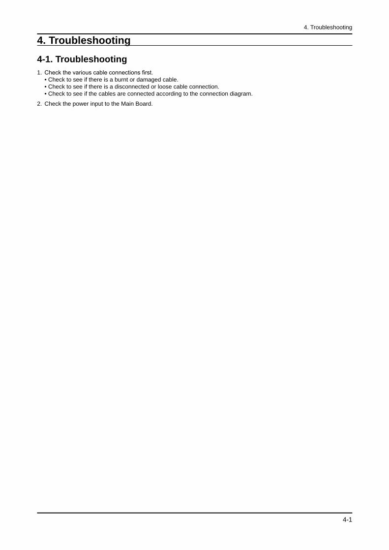
4-1
4. Troubleshooting
4. Troubleshooting
4-1. TroubleshootingCheck the various cable connections first. • Check to see if there is a burnt or damaged cable. • Check to see if there is a disconnected or loose cable connection. • Check to see if the cables are connected according to the connection diagram.
Check the power input to the Main Board.
1.
2.
4-2
4. Troubleshooting
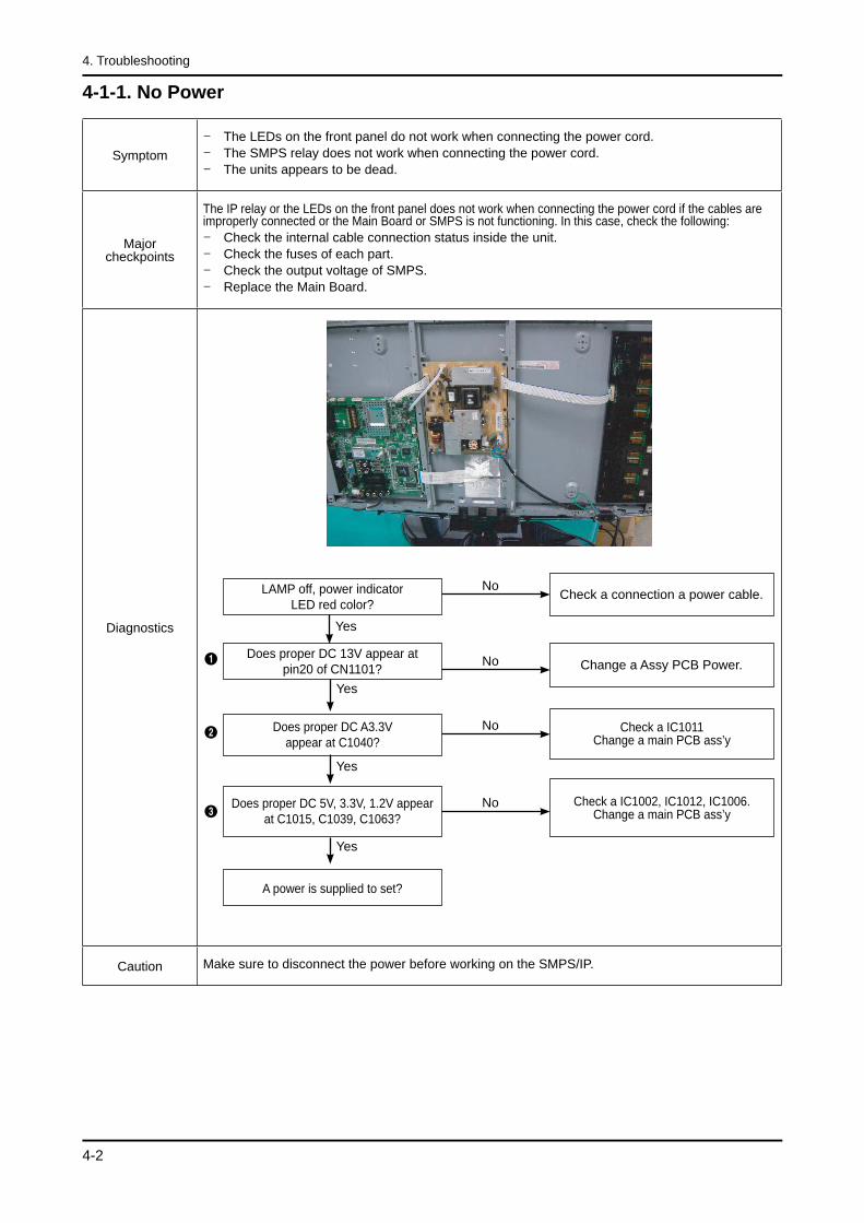
4-1-1. No Power
SymptomThe LEDs on the front panel do not work when connecting the power cord.The SMPS relay does not work when connecting the power cord.The units appears to be dead.
---
Major checkpoints
The IP relay or the LEDs on the front panel does not work when connecting the power cord if the cables are improperly connected or the Main Board or SMPS is not functioning. In this case, check the following:
Check the internal cable connection status inside the unit.Check the fuses of each part.Check the output voltage of SMPS.Replace the Main Board.
----
Diagnostics
Caution Make sure to disconnect the power before working on the SMPS/IP.
Does proper DC A3.3V appear at C1040?
Check a IC1011Change a main PCB ass’y
No
Yes
Does proper DC 5V, 3.3V, 1.2V appear at C1015, C1039, C1063?
No
Yes
LAMP off, power indicatorLED red color?
Yes
NoCheck a connection a power cable.
Does proper DC 13V appear at pin20 of CN1101? No
Yes
A power is supplied to set?
Change a Assy PCB Power.
Check a IC1002, IC1012, IC1006.Change a main PCB ass’y
1
2
3
4-3
4. Troubleshooting
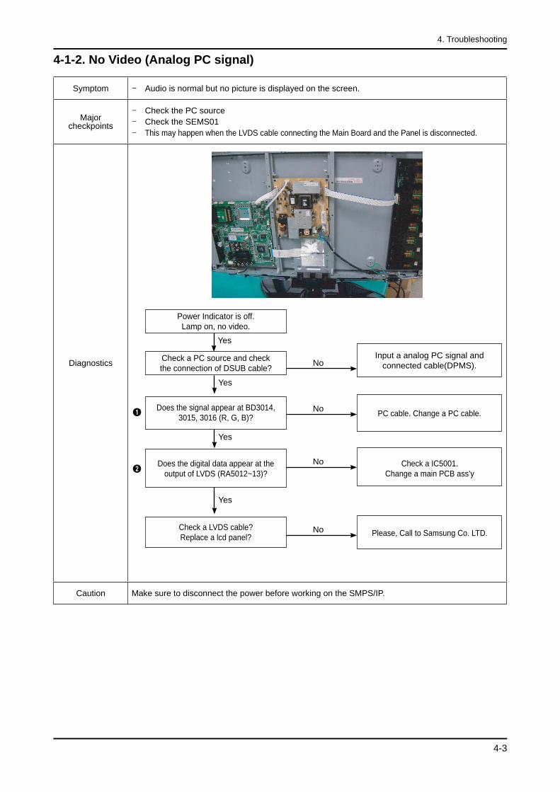
4-1-2. No Video (Analog PC signal)
Symptom Audio is normal but no picture is displayed on the screen.-
Major checkpoints
Check the PC sourceCheck the SEMS01This may happen when the LVDS cable connecting the Main Board and the Panel is disconnected.
-
-
-
Diagnostics
No PC cable. Change a PC cable.
NoDoes the digital data appear at the output of LVDS (RA5012~13)?
Power Indicator is off.Lamp on, no video.
NoCheck a PC source and checkthe connection of DSUB cable?
Check a IC5001.Change a main PCB ass’y
Yes
Does the signal appear at BD3014, 3015, 3016 (R, G, B)?
Please, Call to Samsung Co. LTD.NoCheck a LVDS cable?Replace a lcd panel?
Yes
Yes
Input a analog PC signal andconnected cable(DPMS).
Yes
1
2
Caution Make sure to disconnect the power before working on the SMPS/IP.
4-4
4. Troubleshooting
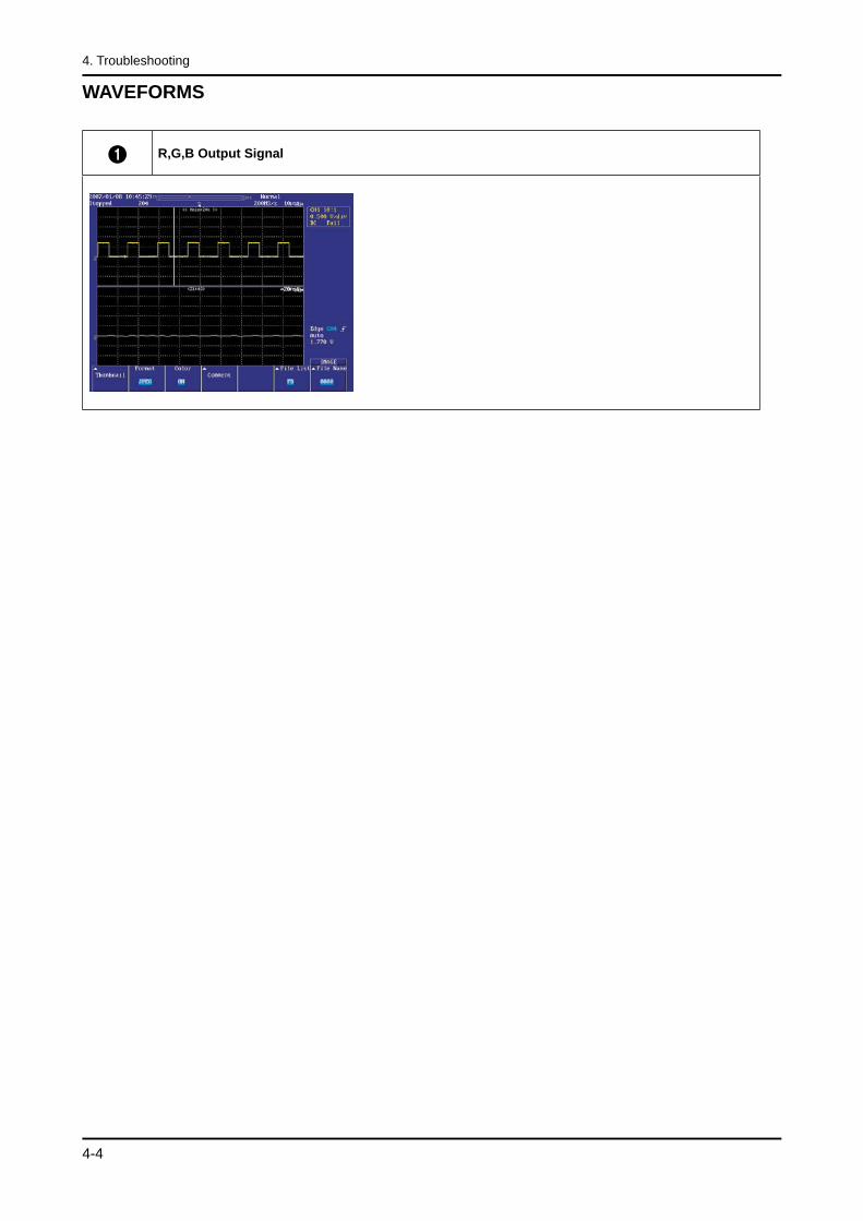
WAVEFORMS
1 R,G,B Output Signal

4-5
4. Troubleshooting
4-1-3. No Video (HDMI - Digital Signal)
Symptom Audio is normal but no picture is displayed on the screen.-
Major checkpoints
Check the HDMI sourceCheck the SEMS01This may happen when the LVDS cable connecting the Main Board and the Panel is disconnected.
-
-
-
Diagnostics
NoDoes the digital data appear at R5055~65?
Power Indicator is off.Lamp on, no video.
NoCheck the connectionof HDMI cable?
Check a IC3001.Change a main PCB ass’y.
Check a IC5001.Change a main PCB ass’y.
NoDoes the digital data appear at the Nooutput of LVDS (RA5012~14)?
NoPlease, Contact Tech support
Check the LVDS cable?Replace the LCD panel?
Yes
Yes
Input a HDMI cable.
Yes
Yes
2
3
1
Caution Make sure to disconnect the power before working on the SMPS/IP.
4-6
4. Troubleshooting
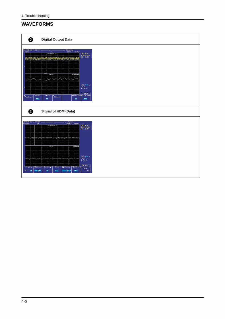
WAVEFORMS
2 Digital Output Data
3 Signal of HDMI(Data)

4-7
4. Troubleshooting
4-1-4. No Video (Tuner_CVBS)
Symptom Audio is normal but no picture is displayed on the screen.-
Major checkpoints
Check the Tuner CVBS sourceCheck the SEMS01This may happen when the LVDS cable connecting the Main Board and the Panel is disconnected.
-
-
-
Diagnostics
No Check a B+ voltage (#3 of Tuner) 5V, change a main PCB ass’y.
No
NoPower Indicator is off.Lamp on, no picure.
Yes
Change a main PCB ass’y.
Does the signal appear at L3001?
Does the signal appear at R3169 of IC2601?
NoPlease, Call to Samsung Co. LTD.
Check the LVDS cable?Replace the LCD panel?
Yes
Connect the RF cable andcheck RF signal.
Yes
1
2
Caution Make sure to disconnect the power before working on the SMPS/IP.
4-8
4. Troubleshooting
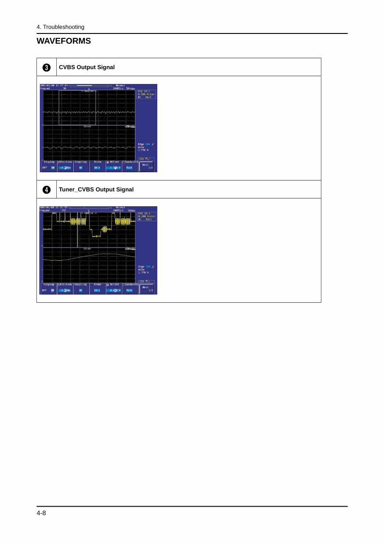
WAVEFORMS
3 CVBS Output Signal
4 Tuner_CVBS Output Signal
4-9
4. Troubleshooting
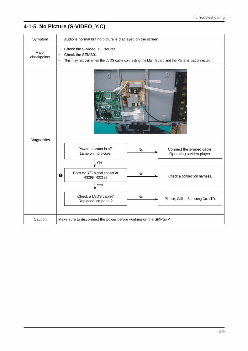
4-1-5. No Picture (S-VIDEO_Y,C)
Symptom Audio is normal but no picture is displayed on the screen.-
Major checkpoints
Check the S-Video_Y,C sourceCheck the SEMS01This may happen when the LVDS cable connecting the Main Board and the Panel is disconnected.
-
-
-
Diagnostics
No Check a connection harness.
NoPower Indicator is off.Lamp on, no picure.
Does the Y/C signal appear at R3299, R3219?
No Please, Call to Samsung Co. LTD.Check a LVDS cable?Replacea lcd panel?
Yes
Connect the s-video cable.Operating a video player.
1
Yes
Caution Make sure to disconnect the power before working on the SMPS/IP.
4-10
4. Troubleshooting
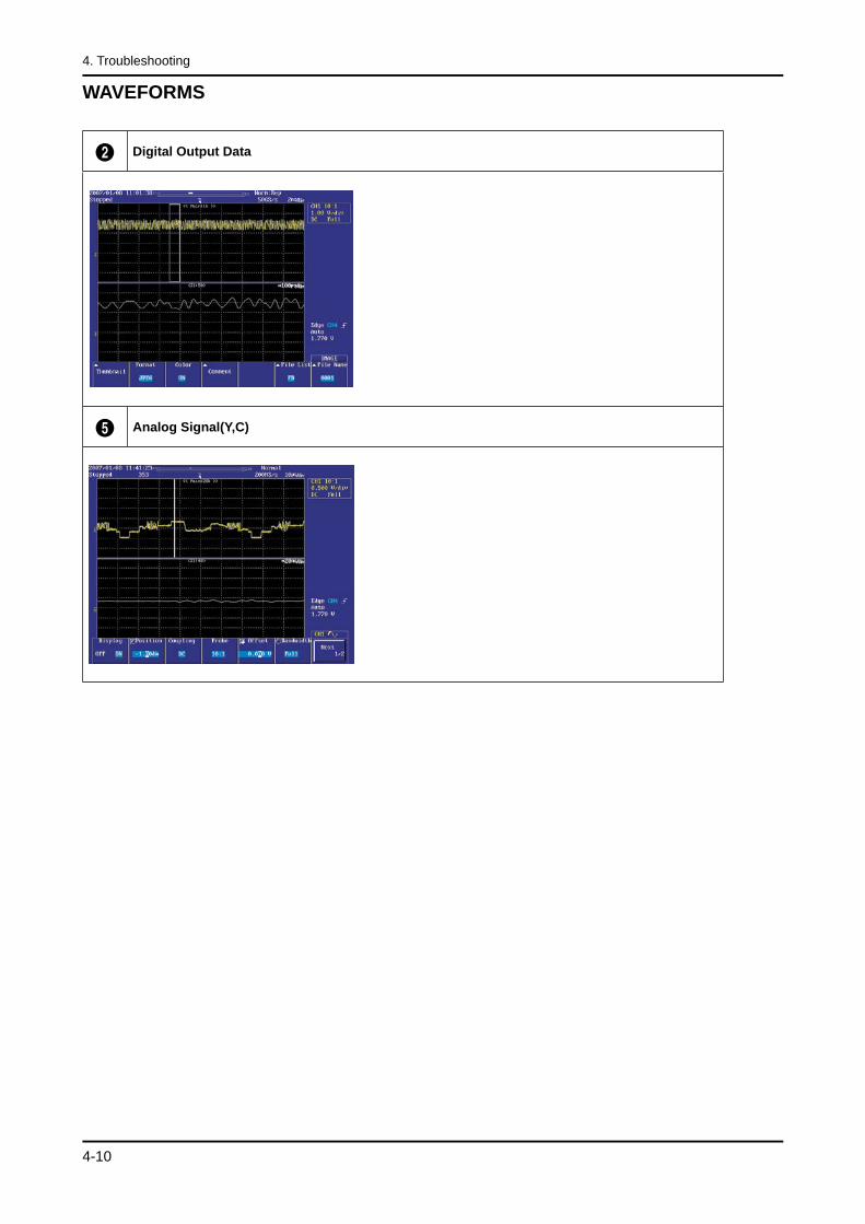
WAVEFORMS
2 Digital Output Data
5 Analog Signal(Y,C)
4-11
4. Troubleshooting
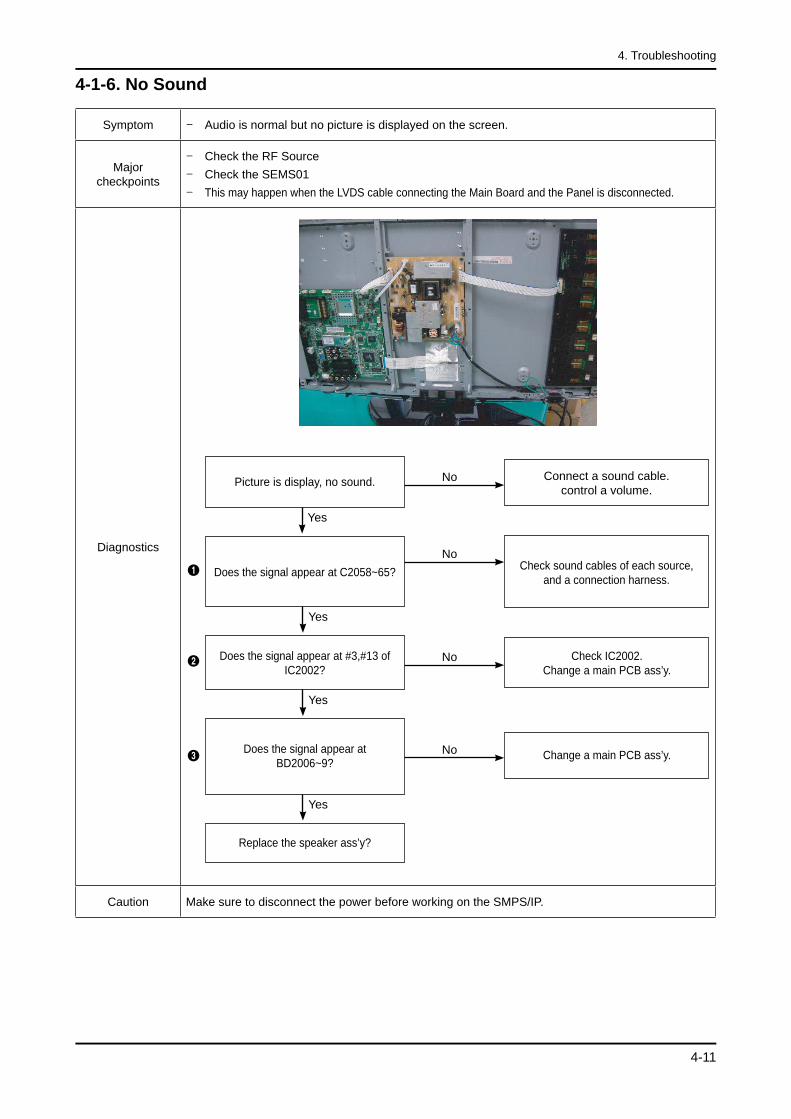
4-1-6. No Sound
Symptom Audio is normal but no picture is displayed on the screen.-
Major checkpoints
Check the RF SourceCheck the SEMS01This may happen when the LVDS cable connecting the Main Board and the Panel is disconnected.
-
-
-
Diagnostics
NoCheck sound cables of each source,
and a connection harness.
NoPicture is display, no sound.
Check IC2002. Change a main PCB ass’y.
No
Does the signal appear at C2058~65?
Does the signal appear at #3,#13 of IC2002?
Change a main PCB ass’y.NoDoes the signal appear atBD2006~9?
Replace the speaker ass’y?
Yes
Connect a sound cable.control a volume.
Yes
1
Yes
3
Yes
2
Caution Make sure to disconnect the power before working on the SMPS/IP.
4-12
4. Troubleshooting
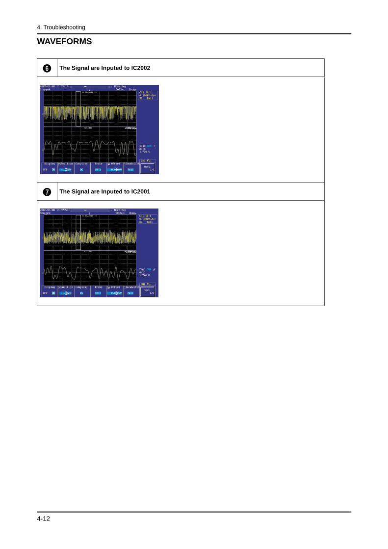
WAVEFORMS
6 The Signal are Inputed to IC2002
7 The Signal are Inputed to IC2001
4-13
4. Troubleshooting
4-2. Alignments and Adjustments
4-2-1. General Alignment InstuctionUsually, a color LCD-TV needs only slight touch-up adjustment upon installation. Check the basic characteristics such as height, horizontal and vertical sync.
Use the specified test equipment or its equivalent.
Correct impedance matching is essential.
Avoid overload. Excessive signal from a sweep generator might overload the front-end of the TV. When inserting signal markers, do not allow the marker generator to distort test result.
Connect the TV only to an AC power source with voltage and frequency as specified on the backcover nameplate.
Do not attempt to connect or disconnect any wire while the TV is turned on. Make sure that the power cord is disconnected before replacing any parts.
To protect against shock hazard, use an isolation transformer.
1.
2.
3.
4.
5.
6.
7.
4-14
4. Troubleshooting
4-3. Factory Mode Adjustments
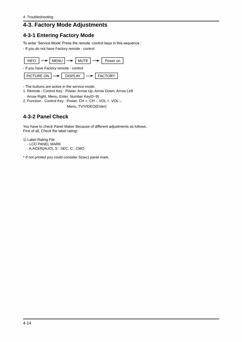
4-3-1 Entering Factory ModeTo enter ‘Service Mode’ Press the remote -control keys in this sequence :- If you do not have Factory remote - control
MENUINFO MUTE Power on
- If you have Factory remote - control
DISPLAYPICTURE ON FACTORY
- The buttons are active in the service mode. 1. Remote - Control Key : Power, Arrow Up, Arrow Down, Arrow Left Arrow Right, Menu, Enter, Number Key(0~9) 2. Function - Control Key : Power, CH +, CH -, VOL +, VOL -, Menu, TV/VIDEO(Enter)
4-3-2 Panel Check You have to check Panel Maker Because of different adjustments as follows.First of all, Check the label rating! 1) Label Rating File - LCD PANEL MARK A:ACER(AUO), S : SEC, C : CMO * If not printed you could consider S(sec) panel mark.
4-15
4. Troubleshooting
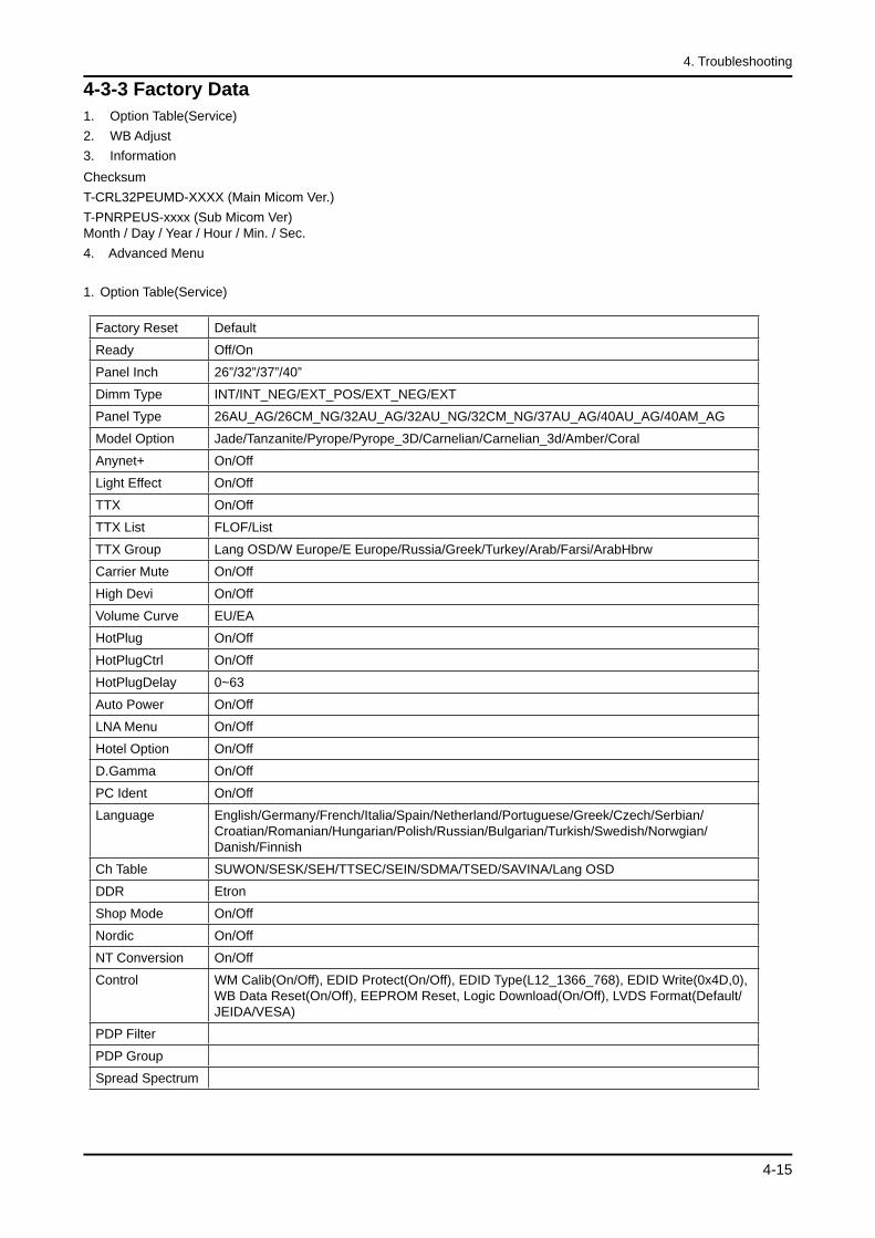
4-3-3 Factory Data Option Table(Service) WB Adjust Information
Checksum T-CRL32PEUMD-XXXX (Main Micom Ver.)T-PNRPEUS-xxxx (Sub Micom Ver) Month / Day / Year / Hour / Min. / Sec.4. Advanced Menu
Option Table(Service)
Factory Reset Default
Ready Off/On
Panel Inch 26”/32”/37”/40”
Dimm Type INT/INT_NEG/EXT_POS/EXT_NEG/EXT
Panel Type 26AU_AG/26CM_NG/32AU_AG/32AU_NG/32CM_NG/37AU_AG/40AU_AG/40AM_AG
Model Option Jade/Tanzanite/Pyrope/Pyrope_3D/Carnelian/Carnelian_3d/Amber/Coral
Anynet+ On/Off
Light Effect On/Off
TTX On/Off
TTX List FLOF/List
TTX Group Lang OSD/W Europe/E Europe/Russia/Greek/Turkey/Arab/Farsi/ArabHbrw
Carrier Mute On/Off
High Devi On/Off
Volume Curve EU/EA
HotPlug On/Off
HotPlugCtrl On/Off
HotPlugDelay 0~63
Auto Power On/Off
LNA Menu On/Off
Hotel Option On/Off
D.Gamma On/Off
PC Ident On/Off
Language English/Germany/French/Italia/Spain/Netherland/Portuguese/Greek/Czech/Serbian/Croatian/Romanian/Hungarian/Polish/Russian/Bulgarian/Turkish/Swedish/Norwgian/ Danish/Finnish
Ch Table SUWON/SESK/SEH/TTSEC/SEIN/SDMA/TSED/SAVINA/Lang OSD
DDR Etron
Shop Mode On/Off
Nordic On/Off
NT Conversion On/Off
Control WM Calib(On/Off), EDID Protect(On/Off), EDID Type(L12_1366_768), EDID Write(0x4D,0), WB Data Reset(On/Off), EEPROM Reset, Logic Download(On/Off), LVDS Format(Default/JEIDA/VESA)
PDP Filter
PDP Group
Spread Spectrum
1.2.3.
1.
4-16
4. Troubleshooting
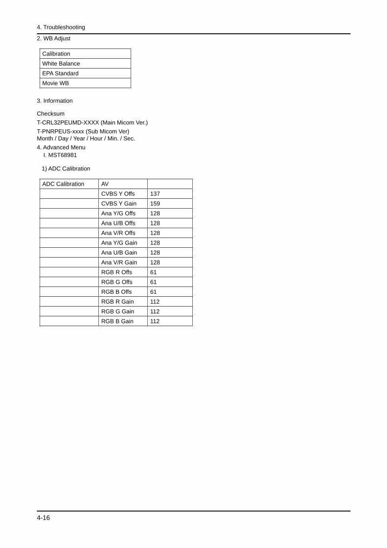
2. WB Adjust
Calibration
White Balance
EPA Standard
Movie WB
3. Information Checksum T-CRL32PEUMD-XXXX (Main Micom Ver.)T-PNRPEUS-xxxx (Sub Micom Ver) Month / Day / Year / Hour / Min. / Sec.4. Advanced Menu I. MST68981 1) ADC Calibration
ADC Calibration AV
CVBS Y Offs 137
CVBS Y Gain 159
Ana Y/G Offs 128
Ana U/B Offs 128
Ana V/R Offs 128
Ana Y/G Gain 128
Ana U/B Gain 128
Ana V/R Gain 128
RGB R Offs 61
RGB G Offs 61
RGB B Offs 61
RGB R Gain 112
RGB G Gain 112
RGB B Gain 112
4-17
4. Troubleshooting
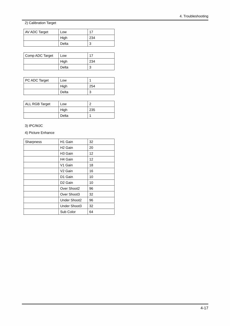
2) Calibration Target
AV ADC Target Low 17
High 234
Delta 3
Comp ADC Target Low 17
High 234
Delta 3
PC ADC Target Low 1
High 254
Delta 3
ALL RGB Target Low 2
High 235
Delta 1
3) IPC/MJC 4) Picture Enhance
Sharpness H1 Gain 32
H2 Gain 20
H3 Gain 12
H4 Gain 12
V1 Gain 18
V2 Gain 16
D1 Gain 10
D2 Gain 10
Over Shoot2 96
Over Shoot3 32
Under Shoot2 96
Under Shoot3 32
Sub Color 64
4-18
4. Troubleshooting
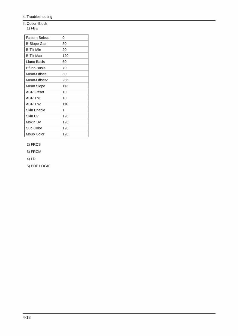
II. Option Block 1) FBE
Pattern Select 0
B-Slope Gain 80
B-Tilt Min 20
B-Tilt Max 120
Lfunc-Basis 60
Hfunc-Basis 70
Mean-Offset1 30
Mean-Offset2 235
Mean Slope 112
ACR Offset 10
ACR Th1 10
ACR Th2 110
Skin Enable 1
Skin Uv 128
Mskin Uv 128
Sub Color 128
Msub Color 128
2) FRCS 3) FRCM 4) LD 5) PDP LOGIC
4-19
4. Troubleshooting
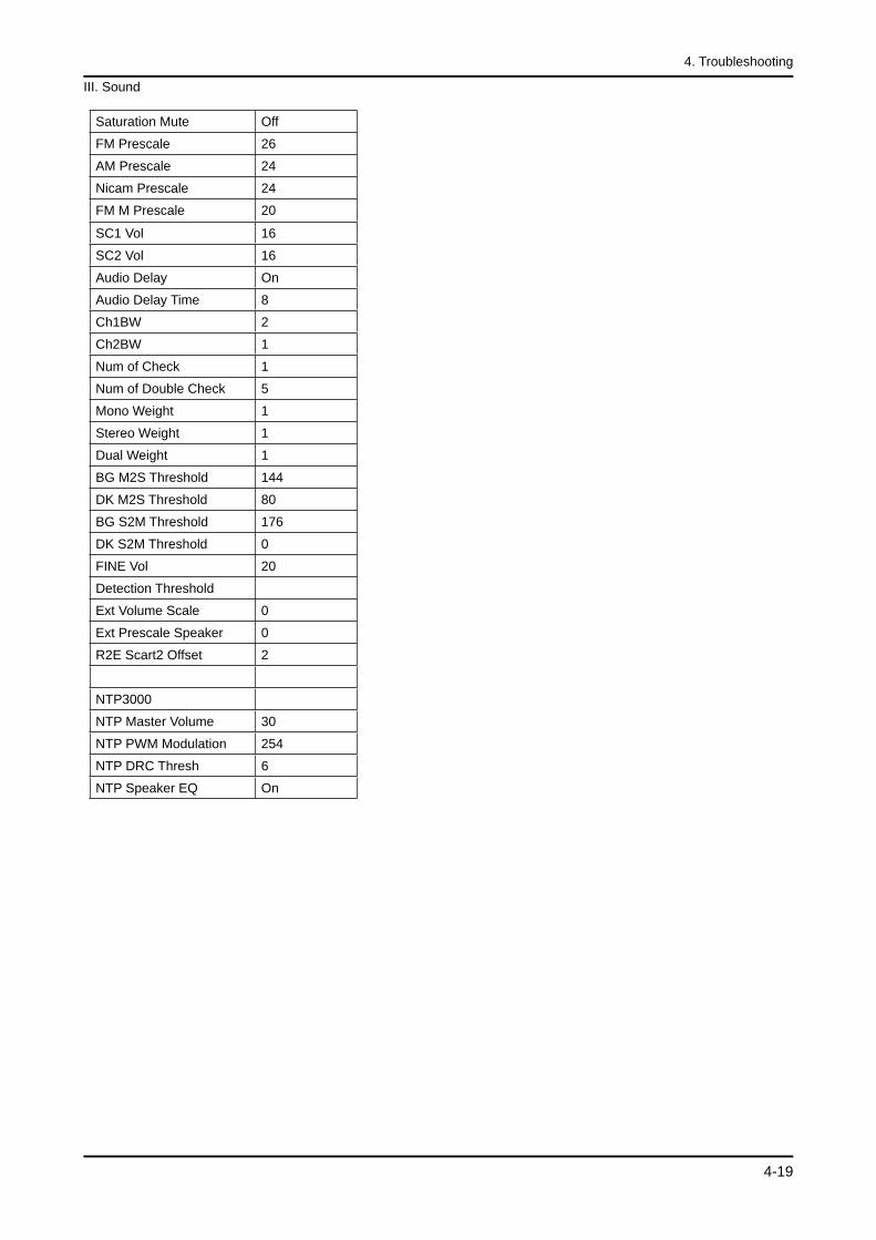
III. Sound
Saturation Mute Off
FM Prescale 26
AM Prescale 24
Nicam Prescale 24
FM M Prescale 20
SC1 Vol 16
SC2 Vol 16
Audio Delay On
Audio Delay Time 8
Ch1BW 2
Ch2BW 1
Num of Check 1
Num of Double Check 5
Mono Weight 1
Stereo Weight 1
Dual Weight 1
BG M2S Threshold 144
DK M2S Threshold 80
BG S2M Threshold 176
DK S2M Threshold 0
FINE Vol 20
Detection Threshold
Ext Volume Scale 0
Ext Prescale Speaker 0
R2E Scart2 Offset 2
NTP3000
NTP Master Volume 30
NTP PWM Modulation 254
NTP DRC Thresh 6
NTP Speaker EQ On
4-20
4. Troubleshooting
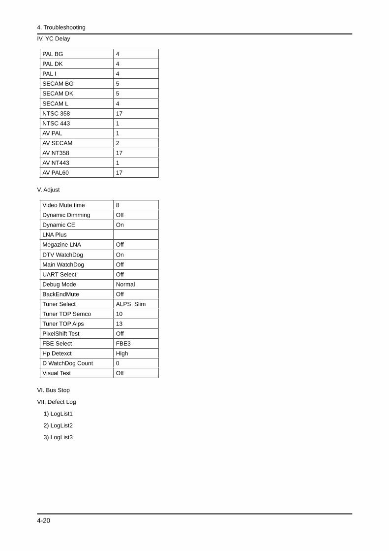
IV. YC Delay
PAL BG 4
PAL DK 4
PAL I 4
SECAM BG 5
SECAM DK 5
SECAM L 4
NTSC 358 17
NTSC 443 1
AV PAL 1
AV SECAM 2
AV NT358 17
AV NT443 1
AV PAL60 17
V. Adjust
Video Mute time 8
Dynamic Dimming Off
Dynamic CE On
LNA Plus
Megazine LNA Off
DTV WatchDog On
Main WatchDog Off
UART Select Off
Debug Mode Normal
BackEndMute Off
Tuner Select ALPS_Slim
Tuner TOP Semco 10
Tuner TOP Alps 13
PixelShift Test Off
FBE Select FBE3
Hp Detexct High
D WatchDog Count 0
Visual Test Off
VI. Bus Stop VII. Defect Log 1) LogList1 2) LogList2 3) LogList3
4-21
4. Troubleshooting
4-4. White Balance - Calibration
4-4-1 White Balance -Calibration
1. Calibration
AV CalibrationComp CalibrationPC CalibrationHDMI Calibration
4-4-2 Service Adjustment - You must perform Calibration in the Lattice Pattern before adjusting the White Balance.
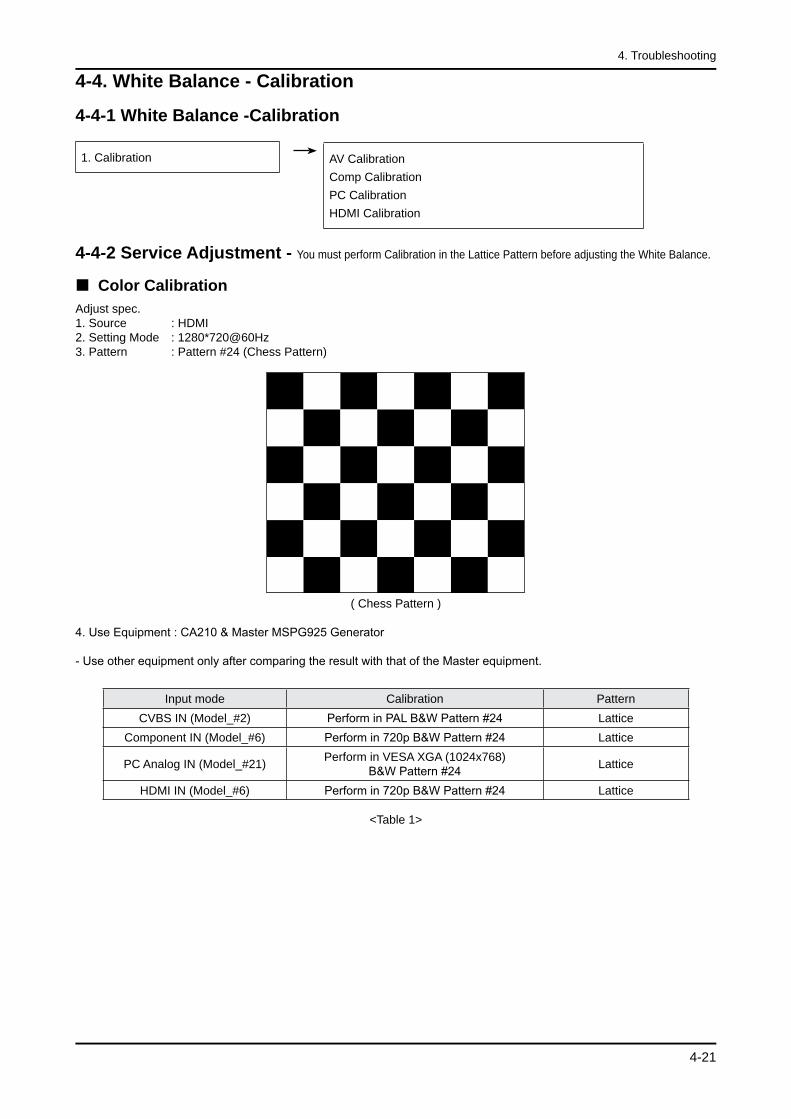
Color CalibrationAdjust spec.1. Source : HDMI2. Setting Mode : 1280*720@60Hz3. Pattern : Pattern #24 (Chess Pattern)
( Chess Pattern )
4. Use Equipment : CA210 & Master MSPG925 Generator
- Use other equipment only after comparing the result with that of the Master equipment.
Input mode Calibration PatternCVBS IN (Model_#2) Perform in PAL B&W Pattern #24 Lattice
Component IN (Model_#6) Perform in 720p B&W Pattern #24 Lattice
PC Analog IN (Model_#21) Perform in VESA XGA (1024x768)B&W Pattern #24 Lattice
HDMI IN (Model_#6) Perform in 720p B&W Pattern #24 Lattice
<Table 1>
4-22
4. Troubleshooting
Method of Color Calibration (AV)1) Apply the NTSC Lattice (N0. 3) pattern signal to the AV IN 1 port2) Press the Source key to switch to “AV1” mode3) Enter Service mode4) Select the “Calibration” menu5) Select the “AV Calibration” menu.6) In “AV Calibration Off” status, press the “ ” key to perform Calibration.7) When Calibration is complete, it returns to the high-level menu.8) You can see the change of the “AV Calibration” status from Failure to Success.
Method of Color Calibration (Component)1) Apply the 720p Lattice (N0. 6) pattern signal to the Component IN 1 port2) Press the Source key to switch to “Component1” mode3) Enter Service mode4) Select the “Calibration” menu5) Select the “Comp Calibration” menu.6) In “Comp Calibration Off” status, press the “ ” key to perform Calibration.7) When Calibration is complete, it returns to the high-level menu.8) You can see the change of the “Comp Calibration” status from Failure to Success.
Method of Color Calibration (PC)1) Apply the VESA XGA Lattice (N0. 21) pattern signal to the PC IN port2) Press the Source key to switch to “PC” mode3) Enter Service mode4) Select the “Calibration” menu5) Select the “PC Calibration” menu.6) In “PC Calibration Off” status, press the “ ” key to perform Calibration.7) When Calibration is complete, it returns to the high-level menu.8) You can see the change of the “PC Calibration” status from Failure to Success.
Method of Color Calibration (HDMI)1) Apply the 720p Lattice (N0. 6) pattern signal to the HDMI1/DVI IN port2) Press the Source key to switch to “HDMI1” mode3) Enter Service mode4) Select the “Calibration” menu5) Select the “HDMI Calibration” menu.6) In “HDMI Calibration Off” status, press the “ ” key to perform Calibration.7) When Calibration is complete, it returns to the high-level menu.8) You can see the change of the “HDMI Calibration” status from Failure to Success.
4-23
4. Troubleshooting
4-4-3 White Balance - Adjustment
3. W/B
(low light) (hight light)
Sub BrightR offsetG offsetB offset
Sub ContrastR gainG gainB gain
(W/B adjustment Condition refer next page)
4-5. White Ratio (Balance) Adjustment
You can adjust the white ratio in factory mode (1:Calibration, 3:White-Balance).
Since the adjustment value and the data value vary depending on the input source, you have to adjust these in CVBS, Component 1 and HDMI 1 modes.
The optimal values for each mode are configured by default. (Refer to Table 1, 2) It varies with Panel’s size and Specification.
1.
2.
3.
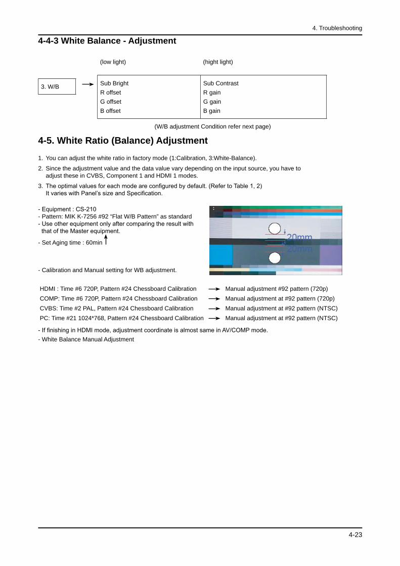
- Equipment : CS-210 - Pattern: MIK K-7256 #92 “Flat W/B Pattern” as standard - Use other equipment only after comparing the result with that of the Master equipment.
- Set Aging time : 60min
- Calibration and Manual setting for WB adjustment.
HDMI : Time #6 720P, Pattern #24 Chessboard Calibration Manual adjustment #92 pattern (720p) COMP: Time #6 720P, Pattern #24 Chessboard Calibration Manual adjustment at #92 pattern (720p) CVBS: Time #2 PAL, Pattern #24 Chessboard Calibration Manual adjustment at #92 pattern (NTSC) PC: Time #21 1024*768, Pattern #24 Chessboard Calibration Manual adjustment at #92 pattern (NTSC)
- If finishing in HDMI mode, adjustment coordinate is almost same in AV/COMP mode.- White Balance Manual Adjustment
4-24
4. Troubleshooting
CA-210x y Y(L) T(K) + MPCD
CVBS(NTSC)
H/L 272 287 -(Sub_CT:145) 11,000 (+10)
L/L 272 287 12.2cd/m2
(3.52 Ft - Sub_BR:128) 11,000 (+10)
COMP(720P)
H/L 272 287 -(Sub_CT:145) 11,000 (+10)
L/L 272 287 12.1cd/m2
(3.5 Ft - Sub_BR:128) 11,000 (+10)
HDMI(720P)
H/L 272 287 -(Sub_CT:145) 11,000 (+10)
L/L 272 287 12.0cd/m2
(3.5 Ft - Sub_BR:128) 11,000 (+10)
- Adjustment Specification White Balance : High light (±3), Low light (±5) Luminance : High light (±0.1Ft/L), Low light (±0.1Ft/L)
4-6. HOW TO UPGRADE
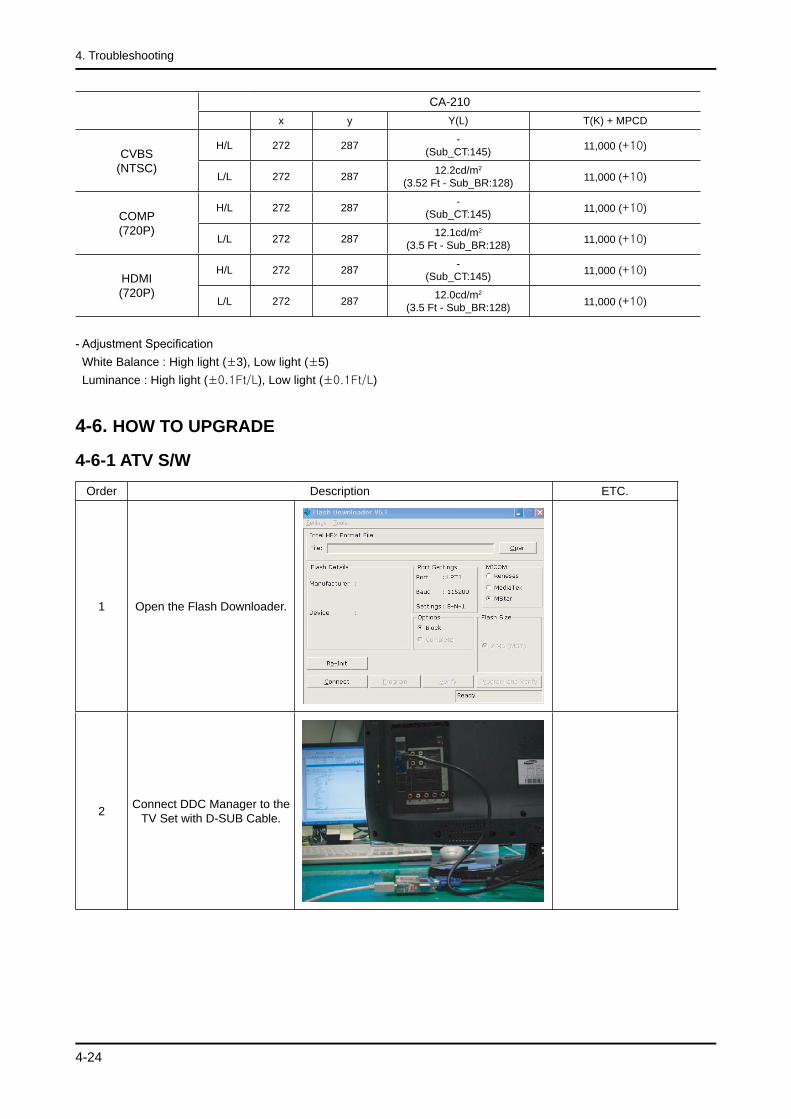
4-6-1 ATV S/WOrder Description ETC.
1 Open the Flash Downloader.
2 Connect DDC Manager to the TV Set with D-SUB Cable.
4-25
4. Troubleshooting
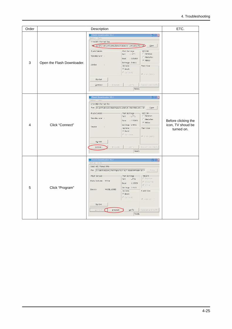
Order Description ETC.
3 Open the Flash Downloader.
4 Click “Connect”Before clicking the icon, TV shoud be
turned on.
5 Click “Program”
4-26
4. Troubleshooting
4-6-2 DTV S/W
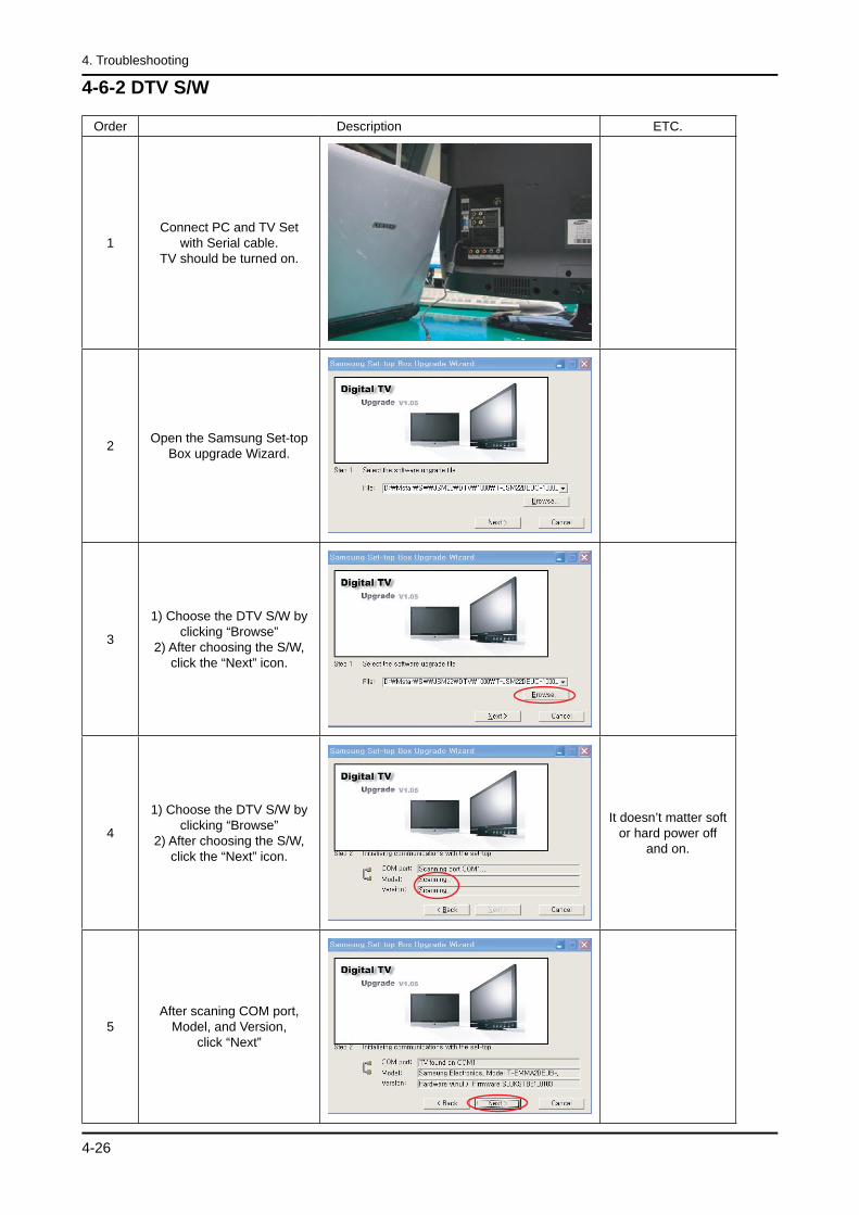
Order Description ETC.
1Connect PC and TV Set
with Serial cable. TV should be turned on.
2 Open the Samsung Set-top Box upgrade Wizard.
3
1) Choose the DTV S/W by clicking “Browse”
2) After choosing the S/W, click the “Next” icon.
4
1) Choose the DTV S/W by clicking “Browse”
2) After choosing the S/W, click the “Next” icon.
It doesn’t matter soft or hard power off
and on.
5After scaning COM port,
Model, and Version, click “Next”
4-27
4. Troubleshooting
4-6-3 After S/W Upgrade
How to Access Service Mode
Entering Factory Mode <Power OFF> → <INFO> → <MENU> → <MUTE> → <Power ON>
Factory DataOption Table(Service)
WB Adjust
Information
Advanced Menu If you want to enter here, press “0000”.
How to Initialize.Click “1. Option Table(Service)” → “Factory Reset” in Factory Menu. You can make every setting in Factory Initial Status.
1.
2.
3.
4.
4-28
4. Troubleshooting
Memo