Embed Size (px)
Citation preview

http://pik.sagepub.com/Dynamics
Engineers, Part K: Journal of Multi-body Proceedings of the Institution of Mechanical
http://pik.sagepub.com/content/228/1/19The online version of this article can be found at:
DOI: 10.1177/1464419313496559published online 30 August 2013
2014 228: 19 originallyProceedings of the Institution of Mechanical Engineers, Part K: Journal of Multi-body DynamicsM Mohammadpour, S Theodossiades, H Rahnejat and P Kelly
Transmission efficiency and noise, vibration and harshness refinement of differential hypoid gear pairs
Published by:
http://www.sagepublications.com
On behalf of:
Institution of Mechanical Engineers
can be found at:Proceedings of the Institution of Mechanical Engineers, Part K: Journal of Multi-body DynamicsAdditional services and information for
http://pik.sagepub.com/cgi/alertsEmail Alerts:
http://pik.sagepub.com/subscriptionsSubscriptions:
http://www.sagepub.com/journalsReprints.navReprints:
http://www.sagepub.com/journalsPermissions.navPermissions:
http://pik.sagepub.com/content/228/1/19.refs.htmlCitations:
What is This?
- Aug 30, 2013OnlineFirst Version of Record
- Feb 20, 2014Version of Record >>
at University of Stellenbosch on November 6, 2014pik.sagepub.comDownloaded from at University of Stellenbosch on November 6, 2014pik.sagepub.comDownloaded from

Original Article
Transmission efficiency and noise,vibration and harshness refinementof differential hypoid gear pairs
M Mohammadpour1, S Theodossiades1, H Rahnejat1 andP Kelly2
Abstract
This article presents a combined multi-body dynamics and lubricated contact mechanics model of vehicular differential
hypoid gear pairs, demonstrating the transient nature of transmission efficiency and noise, vibration and harshness
performance under various driving conditions. The contact of differential hypoid gears is subjected to mixed thermo-
elastohydrodynamic regime of lubrication. The coefficient of friction is obtained using an analytical approach for
non-Newtonian lubricant shear and supplemented by boundary interactions for thin films. Additionally, road data and
aerodynamic effects are used in the form of resisting torque applied to the output side of the gear pair. Sinusoidal engine
torque variation is also included to represent engine order torsional input resident on the pinion gear. Analysis results
are presented for New European Driving Cycle transience from low-speed city driving condition in second gear to
steady-state cruising in fourth gear for a light truck. It is shown that the New European Driving Cycle captures the
transmission efficiency characteristics of the differential hypoid gear pair under worst case scenario, with its underlying
implications for fuel efficiency and emissions. However, it fails to address the other key attribute, being the noise,
vibration and harshness performance. In the case of hypoid gears, the resultant noise, vibration and harshness charac-
teristics can be particularly annoying. It is concluded that broader transient manoeuvres encompassing New European
Driving Cycle are required for assessment, in order to obtain a balanced approach for transmission efficiency and noise,
vibration and harshness performance. This approach is undertaken in this article, which is not hitherto reported in the
literature.
Keywords
Multi-body dynamics, differential hypoid gears, transmission efficiency, noise, vibration and harshness
Date received: 18 February 2013; accepted: 28 May 2013
Introduction
The high load-carrying capacity, usually required ofthe final drive, constitutes partially conforming mesh-ing teeth pairs at relatively high loads. This require-ment brings about the use of hypoid gear pairgeometry, which presents gradual changes in thegeometry of an elliptical contact footprint betweenthe teeth flanks. Therefore, since the inception of theautomobile, the differential hypoid gear pairs withtheir orthogonal axes have become the final drive fea-ture in all vehicles. They are one of the most import-ant elements of the drive train system, particularly inthe current trend towards better fuel efficiency,enhanced power and improved noise, vibration andharshness (NVH) refinement.
Most research works on gearing systems are dedi-cated to the dynamics of parallel axis transmissions,with only limited investigations reported for thedynamics of non-parallel axes gears, such as hypoid
and bevel gears.1–5 This dearth of analysis has beendue to the complexity of their contact kinematics andmeshing characteristics.
The hypoid gear teeth pairs form elliptical contactfootprints and are often subjected to high loads of theorder of several kilonewtons, particularly in the caseof commercial vehicles. The regime of lubricationis usually elastohydrodynamic with a thin film oflubricant being crucial for reducing friction, thus pro-viding enhanced transmission efficiency and reducedNVH.6,7 NVH refinement is increasingly regarded by
Proc IMechE Part K:
J Multi-body Dynamics
2014, Vol. 228(1) 19–33
! IMechE 2013
Reprints and permissions:
sagepub.co.uk/journalsPermissions.nav
DOI: 10.1177/1464419313496559
pik.sagepub.com
1Wolfson School of Mechanical and Manufacturing Engineering,
Loughborough University, Loughborough, UK2Ford Werke GmbH, Cologne, Germany
Corresponding author:
H Rahnejat, Wolfson School of Mechanical and Manufacturing
Engineering, Loughborough University, Ashby Road, Loughborough
LE11 3TU, UK.
Email: [email protected]
at University of Stellenbosch on November 6, 2014pik.sagepub.comDownloaded from
vehicle customers as a key attribute, particularly withregard to disconcerting noises, such as transmissionrattle,8,9 axle whine6,10,11 and the metallic high fre-quency clonk phenomenon in rear wheel drive vehi-cles.12,13 The high frequency NVH responses requirethe inclusion of component flexibility into the impul-sive transient analysis.13
Thus far, most reported dynamic models considerdry contact analysis, which is an unrealistic assump-tion with regard to the estimation of friction. A recentwork by Karagiannis et al.6 presented a dynamicmodel of hypoid gears, focusing on the torsionalvibrations of a differential gear pair under realisticloading conditions. They considered a quasi-staticanalytical elastohydrodynamic lubrication (EHL)analysis, taking into account the non-Newtonianshear of thin lubricant films and generated heat,thus estimating contact friction. They also includedthe effect of dynamic transmission error (DTE).A more detailed numerical solution for the lubricatedcontact with the resultant transmission efficiency isprovided by Mohammadpour et al.7
The main difficulty in the study of EHL of hypoidgears is their complex meshing geometry, which isobtained in the studies by both Karagiannis et al.6
and Mohammadpour et al.7 using tooth contact ana-lysis (TCA).14–16 This approach is applied, using theCALYX commercial software.17 In order to study thedynamics of the gear pair, realistic data, particularlyestimation of the dynamic load is required.6,7
This article presents a multi-body dynamics modelof differential hypoid gear pairs, demonstrating theinteractions between gear pair dynamics and NVHwith friction in the elastohydrodynamic teeth pairconjunctions during meshing. The multi-body modelcomprises a 2 degree of freedom torsional modeldeveloped in the ADAMS multi-body environment.The coefficient of friction is calculated using the avail-able analytical formulae for thin non-Newtonian filmsin lubricated conjunctions. Additionally, road dataand aerodynamic effects are included in the form ofresistance applied to the output side of the gear pair(i.e. originating from the road wheels). The usualsinusoidal variation in engine torque (as the resultof engine order vibrations) is also included in themodel.6
A thin lubricant film is formed during most of themeshing cycle.7 Thus, mixed regime of lubrication isprevalent. The Greenwood and Tripp18 model is usedto take into account the effect of any interactions ofthe ubiquitous asperities on the contiguous contactingmeshing teeth surfaces. The film thickness and ineffi-ciency have been calculated in conjunction with geardynamics and the NVH behaviour of the gear pair.The study integrates the tribological efficiency ofhypoid gears with multi-body dynamics of the finaldrive system, incorporating road wheel traction andvehicle inertial dynamics. The main contributionof this article is the development of a combined
dynamics and tribological model in order to takeinto account the interactions between key differentialsystem attributes. These are NVH refinement and effi-ciency. This approach has not been hitherto reportedin the literature.
Model description
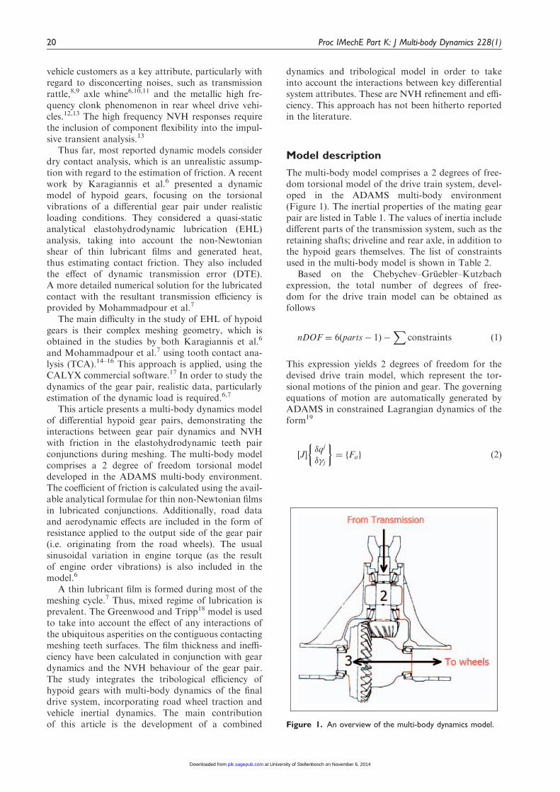
The multi-body model comprises a 2 degrees of free-dom torsional model of the drive train system, devel-oped in the ADAMS multi-body environment(Figure 1). The inertial properties of the mating gearpair are listed in Table 1. The values of inertia includedifferent parts of the transmission system, such as theretaining shafts; driveline and rear axle, in addition tothe hypoid gears themselves. The list of constraintsused in the multi-body model is shown in Table 2.
Based on the Chebychev–Gruebler–Kutzbachexpression, the total number of degrees of free-dom for the drive train model can be obtained asfollows
nDOF ¼ 6 parts� 1ð Þ �X
constraints ð1Þ
This expression yields 2 degrees of freedom for thedevised drive train model, which represent the tor-sional motions of the pinion and gear. The governingequations of motion are automatically generated byADAMS in constrained Lagrangian dynamics of theform19
J½ ��qj
��j
� �¼ Faf g ð2Þ
Figure 1. An overview of the multi-body dynamics model.
20 Proc IMechE Part K: J Multi-body Dynamics 228(1)
at University of Stellenbosch on November 6, 2014pik.sagepub.comDownloaded from
where qj� �¼ x, y, z, , �,�� �T
are the generalisedEulerian co-ordinates and J½ � is the Jacobian matrixof the form
J½ � ¼
@K
@ _qjþ@U
@qj
� �@Cik
@�j
� �
@Cik
@qj
� �0½ �
266664
377775
where j refers to co-ordinates i, k � pð pinionÞ,gð gearÞ, K is the kinetic energy and U the potentialenergy. Thus, the generalised Eulerian resistive forcesare Fqj ¼ �
@U@qj, which in the cases of bodies i, k in this
example are
F i ¼ km f lð Þcm _ i ð3Þ
where i, k 2 p, g, km is the dynamic meshing stiffnessobtained through TCA,6 cm is the structural dampingcoefficient and
f lð Þ ¼
l� b l5b
0 �b5 l5 b
lþ b l4� b
8><>: ð4Þ
l denotes the spatial line of approach between themeshing teeth pairs (l / qi 2 x, y, z). This is theDTE; hence
l ¼
Z t
0
Rp pdt�
Z t
0
Rg gdt ð5Þ
�j are unknown Lagrange multipliers and Cik are con-straint functions for joints in the multi-body systemfor the pinion and gear. These are revolute jointed to
the ground (rear axle) for parts i, resulting in the con-straint functions
xi ¼ 0yi ¼ 0zi ¼ 0
sin �i sin ’i ¼ 0sin �i cos’i ¼ 0
ð6Þ
The applied forces Fai are the torques resident on thepinion and the gear, as well as the contribution due toflank friction as
Fai ¼ Ti þ Tfri ð7Þ
The resisting torque applied to the wheels is due totraction, which comprises vehicle inertia (motiveforce), rolling resistance, aerodynamic interactionand grading20
Tg ¼ rwX
F ð8Þ
where rw is the laden wheel radius andP
F isobtained from the vehicle longitudinal dynamics asthe remaining degree of freedom in the analysis
XF ¼ ma ¼ Ra þ Rrl þ Rg ð9Þ
where
Ra ¼�
2CDAfV
2 ð10Þ
Rrl ¼ frlW ð11Þ
and
frl ¼ 0:01 1þV
147
� ð12Þ
The demanded instantaneous input torque (on thepinion) is obtained as
Tp ¼Rp
RgTg 1þ 0:1 cos 2RtAp
� �ð13Þ
The sinusoidal variation as the result of engine ordervibration is represented in equation (13) as 10% oscil-lations about the nominal engine speed as its secondharmonic for the four-cylinder four-stroke configur-ation,19 subject of this study. With manoeuvres onnominally flat terrains, the grading contribution isignored.
The flank friction between pairs of meshing gearteeth contributes to the applied forcing (equation(7)). A thin elastohydrodynamic lubricant film is usu-ally formed in the conjunctions of the meshingteeth pairs of the differential hypoid gears. Thesethin lubricant films are subject to non-Newtonian
Table 2. List of constraints in the multi-body model.
Part I Part J Constraint type
Number of
constraints
Pinion Ground Revolute 5
Gear Ground Revolute 5
Table 1. Inertial part list.
Part number Part name Inertia (kg m2)
1 Ground —–
2 Pinion 1734� 10�6
3 Gear 5.81� 10�2
Mohammadpour et al. 21
at University of Stellenbosch on November 6, 2014pik.sagepub.comDownloaded from
viscous shear, supplemented by any asperity inter-actions (boundary friction as the result of any directcontact of surfaces)
Tfri ¼ Rifr ð14Þ
where the flank friction is obtained as
fr ¼ fv þ fb ð15Þ
The viscous friction is calculated using
fr ¼ �Wi ð16Þ
Evans and Johnson21 presented an analytical–experi-mental expression for the coefficient of friction basedon the prevailing regime of lubrication. In fullyflooded lubricated contacts, friction is due to shearstress of the lubricant film. Based on the prevailingconditions, the shear behaviour of lubricant canreside in one of the following four regimes of lubrica-tion: (a) linear viscous or Newtonian; (b) non-linearviscous or non-Newtonian; (c) visco-elastic and (d)elasto-plastic. Usually in machine elements the elasticterm is negligible22 and viscous models can definethe behaviour of the lubricant. In addition, theNewtonian behaviour can be considered as a simpli-fied form of the overall behaviour of lubricant undernon-Newtonian shear. Then, regime (b) (i.e. non-Newtonian) can be used for most of the conditionsencountered. Equation (17) is obtained by consideringthis overall behaviour of the lubricant. Then, theshear stress grows with shear rate in a non-linearmanner and decreases due to any temperature riseand the ensuing reduction in lubricant viscosity.These effects have been investigated by Crook.23
Johnson and Greenwood24 have used the sameapproach. Equation (17) embodies their approach inorder to take into account the thermal effects andpressure dependence of lubricant rheological stateunder non-Newtonian shear
� ¼ 0:87�0 þ 1:740�p
ln1:2
0hco
2 _K01þ 9:6&
!1=20@
1Að17Þ
where
� ¼4
�
_K
hco=R0P
E0R0K0�0c0U0
� 1=2
ð18Þ
To obtain boundary friction, the Greenwood andTripp18 model is used. This model assumes aGaussian distribution of asperity heights, with amean radius of curvature for an asperity summit.
The area Aa of asperity contact and the load carriedPa may be estimated as
Aa ¼ �2 ��ð Þ
2AF2 �ð Þ ð19Þ
Pa ¼8ffiffiffi2p
15� ��ð Þ
2
ffiffiffi�
�
rE0AF5
2�ð Þ ð20Þ
In these formulae, A is the apparent contact area, isthe density of asperity peaks per unit area of contactand � is the average summit radius of the curvature ofasperities. The statistical functions F2 and F5/2, givenbelow, are dependent on the Stribeck’s oil film par-ameter �¼ h/�
� ¼ffiffiffiffiffiffiffiffiffiffiffiffiffiffiffiffi�21 þ �
22
qð21Þ
where �1 and �2 are the average asperity heights of thetwo contiguous contacting surfaces, respectively.
The film thickness h is obtained from the extrapo-lated expression obtained numerically by Chittendenet al.25 for an elliptical point contact with angledlubricant flow entrainment into the conjunction
h�c0 ¼ 4:31U�0:68
G�:49
W��0:073
1� exp �1:23Rs
Re
� 2=3" #( )
ð22Þ
where the non-dimensional groups are
W� ¼�Wj
2ErRe2U� ¼
�0uj4ErRe
G� ¼2
�Er�ð Þ and
1
Re¼
cos2�
Rzxþsin2�
Rzy,1
Rs¼
sin2�
Rzxþcos2�
Rzy
The statistical functions F2 �ð Þ and F52ð�Þ are defined as
Fn �ð Þ ¼1ffiffiffiffiffiffi2�p
Z 00
�
s� �ð Þnes
2=2ds ð23Þ
According to Teodorescu et al.26 the results of numer-ical integration for these functions of interest andtheir least square fittings yield
F 5=2ð Þ �ð Þ ¼ �0:1922�3 þ 0:721�2 � 1:0649�þ 0:6163
ð24Þ
F2 �ð Þ ¼ �0:116�3 þ 0:4862�2 � 0:7949�þ 0:4999
ð25Þ
According to Greenwood and Tripp,18 the roughnessparameter �� is reasonably constant with a value of0.03–0.05 for steel surfaces while the ratio �
�, which is ameasure of average asperity slope is in the range 10�4
to 10�2 (this being a representation of the
22 Proc IMechE Part K: J Multi-body Dynamics 228(1)
at University of Stellenbosch on November 6, 2014pik.sagepub.comDownloaded from

average asperity slope22). Assuming �1 ¼ �2, then ��¼ 0.040–0.070 and with an average value of ��¼ 0.055, the asperity contact area Aa becomes
Aa ¼ 0:0298AF2 �ð Þ ð26Þ
Considering the same data and assuming ��¼ 0.001,
the load carried by the asperities becomes
Pa ¼ 0:000227E�AF52�ð Þ ð27Þ
The boundary shear is obtained as
b ¼ L0 þ �0Pa ð28Þ
where a thin adsorbed film at the summit of an oppos-ing asperity pair acts in non-Newtonian shear atasperity pressure Pa ¼
Fa
Aa. Thus
fb ¼ bAa ð29Þ
It is necessary to calculate the contact load Wi for allthe simultaneousmeshing teeth pairs, which is requiredfor both equations (16) and (22). This is obtainedthrough TCA. The method is outlined in detail byLitvin and Fuentes.14 Other data for the model are
Table 6. Physical properties of the lubricant and solids.
Pressure viscosity coefficient (a) (Pa�1) 2.383� 10�8
Lubricant atmospheric dynamic viscosity
at 40�C (0) (Pa s)
0.195
Atmospheric dynamic viscosity
at 100�C (0Þ(Pa.s)
0.0171
Lubricant Eyring shear stress 0 (MPa) 2
L0 (MPa) 2.3
Pressure-induced shear coefficient (�0) 0.08
Heat capacity of fluid (J/kg K) 0.14
Thermal conductivity of fluid (W/m K) 2000
Modulus of elasticity of contacting
solids (GPa)
210
Poisson’s ratio of contacting solids (–) 0.3
Density of contacting solids (kg/m3) 7850
Thermal conductivity of contacting
solids (W/m K)
46
Heat capacity of contacting solids (J/kg K) 470
Table 4. Gear parameters.
Parameter name Gear
Number of teeth 36
Face-width (mm) 29.999
Face angle (�) 59.653
Pitch angle (�) 59.653
Root angle (�) 59.653
Spiral angle (�) 27.601
Pitch apex (mm) 8.987
Face apex (mm) 10.948
Outer cone distance (mm) 95.598
Offset (mm) 24
Sense (hand) Left
Table 3. Pinion parameters.
Parameter name Pinion
Number of teeth 13
Face-width (mm) 33.851
Face angle (�) 29.056
Pitch angle (�) 29.056
Root angle (�) 29.056
Spiral angle (�) 45.989
Pitch apex (mm) �9.085
Face apex (mm) 1.368
Outer cone distance (mm) 83.084
Sense (hand) Right
Table 5. Input operating conditions.
Parameter Value
Af (frontal area) 2.2 m2
fr l (coefficient of rolling resistance) 0.0166
CD (drag coefficient) 0.33
� (air density) 1.22 kg/m3
W (vehicle weight) 1300 kg
Tyre (type) P205/65R15 BSW
Second gear ratio 2.038:1
Third gear ratio 1.281:1
4th gear ratio 0.951:1
Surface roughness of solids 0.5 mm
Figure 2. Flank load on subsequent teeth.
Mohammadpour et al. 23
at University of Stellenbosch on November 6, 2014pik.sagepub.comDownloaded from

also obtained through TCA, including the instantan-eous contact radii of curvature of the pinion and gearteeth surfaces and the variation of contact stiffnessduring the meshing cycle. At any instant of time inthe differential hypoid gears, several teeth pairs are incontact in order to carry the high torques generated.TCA calculates the load share per pair of teeth duringany meshing cycle, as well as the corresponding mesh-ing stiffness and the static transmission error.
The geometrical, kinematic and load data requiredfor the EHL and efficiency analysis are also obtainedfrom the TCA. The contact load per teeth pair is afunction of the dynamic response of the system.However, its distribution among teeth pairs in simul-taneous contact is defined quasi-statically. A load dis-tribution factor is calculated as a function of thepinion angle for all such contacts. This is the ratioof the applied load Wj on a given flank under
Figure 3. A typical part of the NEDC.
NEDC: New European Driving Cycle.
Figure 4. Vehicle speed from NEDC condition to highway driving.
NEDC: New European Driving Cycle.
24 Proc IMechE Part K: J Multi-body Dynamics 228(1)
at University of Stellenbosch on November 6, 2014pik.sagepub.comDownloaded from
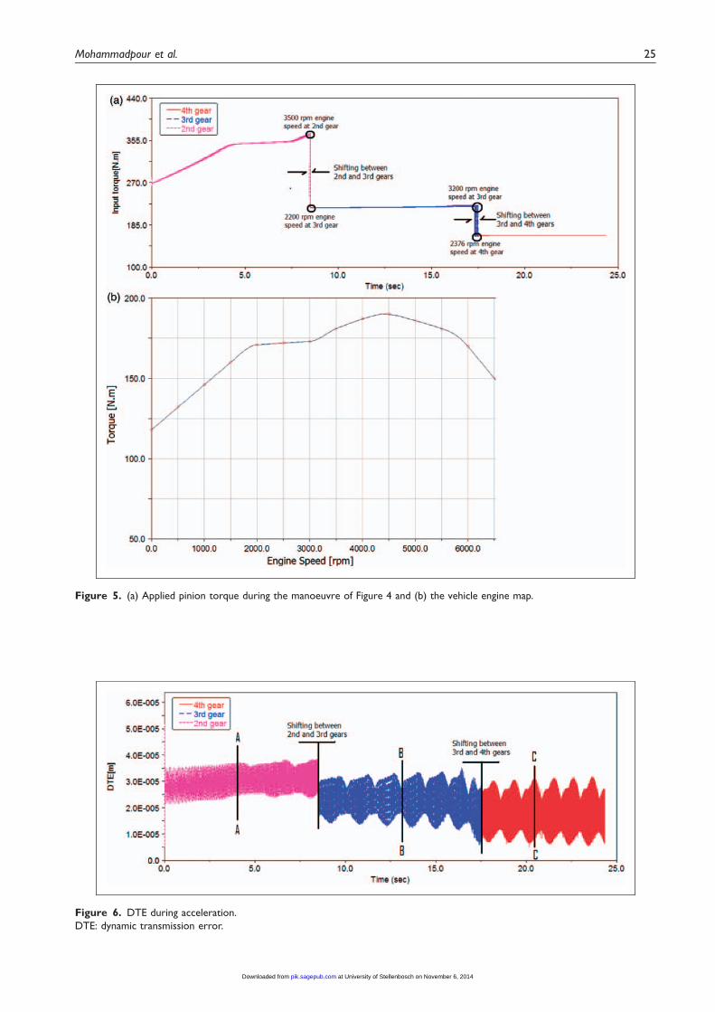
Figure 5. (a) Applied pinion torque during the manoeuvre of Figure 4 and (b) the vehicle engine map.
Figure 6. DTE during acceleration.
DTE: dynamic transmission error.
Mohammadpour et al. 25
at University of Stellenbosch on November 6, 2014pik.sagepub.comDownloaded from

(a)- Wavelet of response for second gear (transient NEDC) and time history of section A-A
fm
fe
fm- fe
fm+ fe
2×fm
3×fm
(b)- Wavelet of response for third gear (transition to highway driving) and time history of section B-B
fm
fe
fm- fe
f m+ fe
2×fm
3×fm
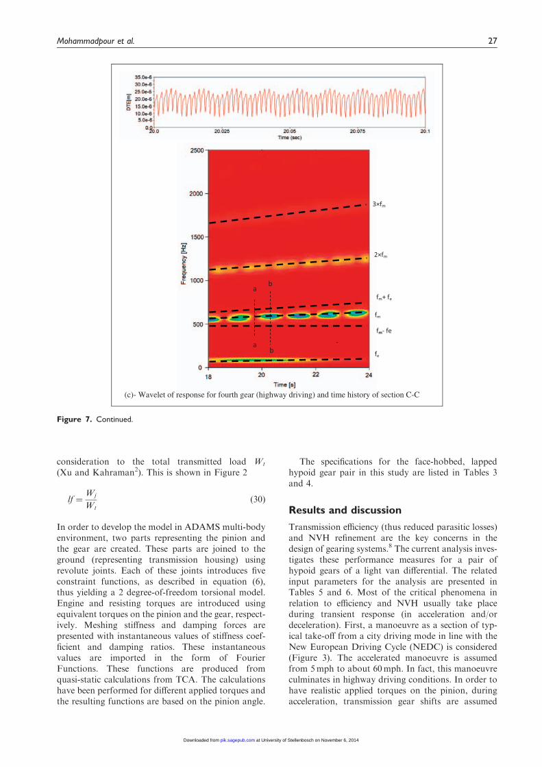
Figure 7. DTE and its spectral content from city to highway driving conditions.
DTE: dynamic transmission error.
26 Proc IMechE Part K: J Multi-body Dynamics 228(1)
at University of Stellenbosch on November 6, 2014pik.sagepub.comDownloaded from
consideration to the total transmitted load Wt
(Xu and Kahraman2). This is shown in Figure 2
lf ¼Wj
Wtð30Þ
In order to develop the model in ADAMS multi-bodyenvironment, two parts representing the pinion andthe gear are created. These parts are joined to theground (representing transmission housing) usingrevolute joints. Each of these joints introduces fiveconstraint functions, as described in equation (6),thus yielding a 2 degree-of-freedom torsional model.Engine and resisting torques are introduced usingequivalent torques on the pinion and the gear, respect-ively. Meshing stiffness and damping forces arepresented with instantaneous values of stiffness coef-ficient and damping ratios. These instantaneousvalues are imported in the form of FourierFunctions. These functions are produced fromquasi-static calculations from TCA. The calculationshave been performed for different applied torques andthe resulting functions are based on the pinion angle.
The specifications for the face-hobbed, lappedhypoid gear pair in this study are listed in Tables 3and 4.
Results and discussion
Transmission efficiency (thus reduced parasitic losses)and NVH refinement are the key concerns in thedesign of gearing systems.8 The current analysis inves-tigates these performance measures for a pair ofhypoid gears of a light van differential. The relatedinput parameters for the analysis are presented inTables 5 and 6. Most of the critical phenomena inrelation to efficiency and NVH usually take placeduring transient response (in acceleration and/ordeceleration). First, a manoeuvre as a section of typ-ical take-off from a city driving mode in line with theNew European Driving Cycle (NEDC) is considered(Figure 3). The accelerated manoeuvre is assumedfrom 5mph to about 60mph. In fact, this manoeuvreculminates in highway driving conditions. In order tohave realistic applied torques on the pinion, duringacceleration, transmission gear shifts are assumed
(c)- Wavelet of response for fourth gear (highway driving) and time history of section C-C
a b
a b
fm
fe
fm- fe
fm+ fe
2×fm
3×fm
Figure 7. Continued.
Mohammadpour et al. 27
at University of Stellenbosch on November 6, 2014pik.sagepub.comDownloaded from
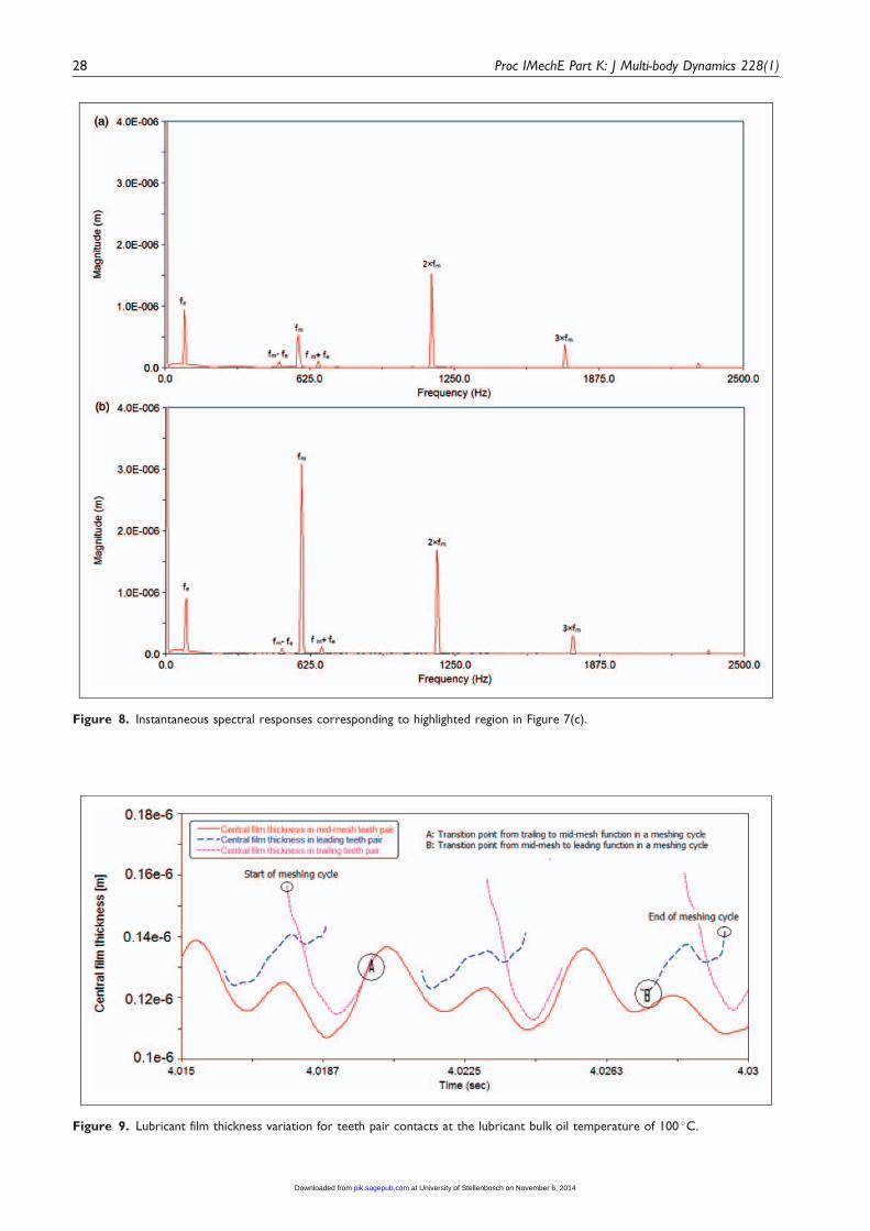
Figure 8. Instantaneous spectral responses corresponding to highlighted region in Figure 7(c).
Figure 9. Lubricant film thickness variation for teeth pair contacts at the lubricant bulk oil temperature of 100 �C.
28 Proc IMechE Part K: J Multi-body Dynamics 228(1)
at University of Stellenbosch on November 6, 2014pik.sagepub.comDownloaded from
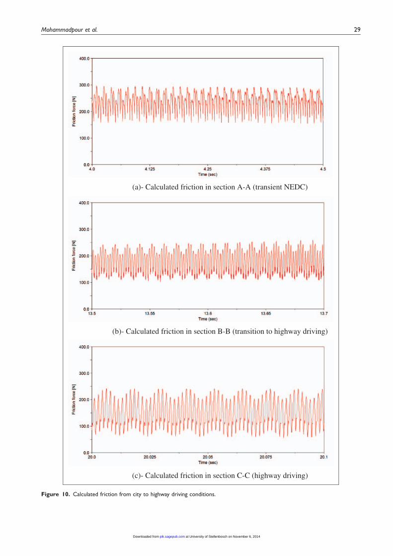
(a)- Calculated friction in section A-A (transient NEDC)
(b)- Calculated friction in section B-B (transition to highway driving)
(c)- Calculated friction in section C-C (highway driving)
Figure 10. Calculated friction from city to highway driving conditions.
Mohammadpour et al. 29
at University of Stellenbosch on November 6, 2014pik.sagepub.comDownloaded from

between second and third gears at 3500 r/min andbetween third and fourth gears at 3200 r/min. Then,acceleration continues up to 3000 r/min engine speed.The calculated speed of vehicle during this process ispresented in Figure 4. For all calculations, 60% wideopen throttle torque is assumed.
The calculated applied torque, Tp (equation (13)),on the pinion is shown in Figure 5(a). This is thetorque variation for the engine map (Figure 5(b))for the gear shifts corresponding to the conditionsin Figure 4.
The predicted DTE during the specified manoeuvreis shown in Figure 6. There are three distinct regionsin the DTE characteristic response shown in Figure 6.These comprise a transient part of the NEDC, markedby the typical instantaneous A-A response, the even-tual highway driving condition C-C and the transitionperiod, regarded as an off-NEDC manoeuvre,represented by the instantaneous response B-B.Figure 7(a)–(c) show the localised time histories inthe above regions (A-A, B-B and C-C) with their cor-responding wavelet plots. Two spectral contributionsdominate the signal in all cases. One is the meshingfrequency, fm, and the other is the forcing frequency(second engine order torsional vibration, resident onthe transmission output shaft of the simulated four-stroke, four-cylinder engine), fe ¼
12� 2RtAp
�(see
equation (13)). Also, note the small modulation effectsbetween these frequencies, fm� fe and fmþ fe as wellas harmonics of the meshing frequency. All spectralcontributions are subject to a gradually increasing fre-quency value owing to the accelerative nature of themanoeuvre (curvilinear characteristic loci). Of note isthe intermittency in the nature of response amplitudeat the meshing frequency (repetitive regions of riseand fall in amplitude in the characteristic locus ofthe meshing frequency), particularly at the highervehicle speeds. Figure 8 shows two spectra of vibra-tion at close instances during meshing (marked
by lines a-a and b-b in Figure 7(c)). Physical interpret-ation of this is amplitude perturbation at the meshingfrequency because of changes in lubricated contactdynamics (slide-roll speed ratio and lubricant reactionthrough mesh). This oscillatory behaviour is known tocause pressure perturbations, which can emanate asnoise. This phenomenon is quite similar to transmis-sion drive rattle condition (with partial loading),8
which causes teeth pair oscillations within the confineof their backlash. For axle whine condition, Koroniaset al.10 noted that diminished amplitude contributionat the meshing frequency or conversely an increasedcontribution at the forcing frequency (engine ordervibration) results in the axle whine phenomenon.The results here conform to their findings: (a) waveletof response for second gear (transient NEDC) andtime history of section A-A; (b) wavelet of responsefor third gear (transition to highway driving) and timehistory of section B-B and (c) wavelet of response forfourth gear (highway driving) and time history of sec-tion C-C.
To obtain flank friction, it is important to calculatethe lubricant film thickness in the conjunctions ofmating meshing gear teeth pairs. At any instant oftime, three pairs of teeth are in simultaneous mesh.The load share per teeth pair, Wj, is obtained fromequation (30) and used together with the instantan-eous contact kinematics, uj (obtained through TCA)and the lubricant rheological parameters (listed inTable 6) in equation (22) to obtain the instantaneousteeth pair lubricant film thickness. This is shown inFigure 9, where the three teeth pairs in simultaneouscontact are denoted by the leading, middle and trail-ing contacting teeth pairs. Note the thin film thicknessof the order of 0.1–0.15 mm, which results in oil filmparameter ratio �5 3, indicating a mixed regime oflubrication, where a percentage area of contact experi-ences direct surface interactions (boundary friction).Furthermore, such thin films at relatively high shear
Figure 11. Transmission inefficiency during acceleration.
30 Proc IMechE Part K: J Multi-body Dynamics 228(1)
at University of Stellenbosch on November 6, 2014pik.sagepub.comDownloaded from
promote non-Newtonian viscous shear, which is thereason for employing equations (17) and (18).
The friction per contacting meshing teeth pairs isobtained using equations (15), (16) and (29). Figure 10shows the flank friction for the same conditions asthose in Figure 7. With an assumed fully floodedlubrication condition, a thicker film is formed inteeth-pair conjunctions through mesh. This decreasesthe viscous shear stress, as well as reducing the con-tribution due to any boundary interactions. Thus,friction reduces at higher speeds as the lubricated con-junction is subjected to elastohydrodynamic regime oflubrication and the lubricant film thickness is insensi-tive to load.22 Conditions that correspond to reducedfriction promote increased residual vibratory energy.Figure 10(a)–(c) shows decreased average friction withincreased vehicle speed, a trend that is inverselyrelated to Figure 7(a)–(c). Thus, differential efficiencyand NVH refinement are contradictory desired attri-butes. The defined NEDC cycle is motivated by fuelefficiency and reduced emissions; thus, it is basedupon low driving speeds, where frictional losses aremore pronounced, without regard to NVH refine-ment. However, various NVH phenomena have pro-gressively become key vehicle customer concerns, aswell as potential sources of warranty claims.10,12
The trend of improved transmission efficiencywith increased vehicle speed is further depictedin Figure 11, which corresponds to the drivingmanoeuvre presented in Figure 5. The transmission
inefficiency is defined as " ¼
PjPfj
T! � 100, where
Pfj ¼ frj� uj is the frictional power loss, � uj is thesliding velocity of teeth pairs j, T and ! are piniontorque and angular velocity, respectively. Figure 11shows that the transmission inefficiency due to differ-ential hypoid gear pair at higher engine speedsaccounts for a mere 1–2% of all the power trainlosses, which is nevertheless quite significant. At lowspeeds, representative of the transient accelerativepart of the NEDC cycle, the transmission inefficiencycan be significantly higher, as shown in Figure 11.These predictions are in line with findings of otherresearchers. For hypoid gears, there have been scoringtests and efficiency measurements by Naruse et al.27
and approximation of power loss for hypoid gears asa combination of spiral bevel gears and a worm gearby Buckingham.28 These studies have indicated trans-mission inefficiency in the order of 2–4%. A morecomprehensive analysis is carried out by Xu et al.,29
who used a combination of TCA and thermo-elastohydrodynamics of hypoid gear pairs to predictthe coefficient of friction. For an assumed lubricantNewtonian behaviour, the transmission mechanicalinefficiency was predicted to be in the range 2–3%.Recently an experimental investigation of axle effi-ciency has been presented by Hurley,30 indicating anoverall efficiency of 2–8% for a range of speeds andtorques.
Conclusions
The results of the analyses indicate that transient testssuch as those described in this article are more repre-sentative when studying combined transmission effi-ciency and NVH refinement, rather than the NEDC,which is heavily focussed only on the assessment offuel efficiency and resulting emissions. The linkbetween NVH refinement and transmission efficiencyhas been investigated. It is shown that NVH perform-ance deteriorates during transient accelerative motion,which at high speeds improves the chance of lubricantfilm formation and decreases transmission ineffi-ciency. The converse is true at low-speed steady-state driving conditions that form the main part ofthe NEDC.
In conclusion, compliance with directives setthrough NEDC is just one trend in the future devel-opments, the other is NVH refinement, which is pro-gressively viewed as a measure of quality.
Funding
The authors would like to express their gratitude to FordMotor Company for support of this research project.
Acknowledgement
The authors thank the Advanced Numerical Solutions Inc.
for access to the TCA tool CALYX.
References
1. Kolivand M and Kahraman A. A loaddistribution model for hypoid gears using ease-off topo-
graphy and shell theory. Mech Mach Theory 2009; 44:1848–1865.
2. Xu H and Kahraman A. Prediction of friction-relatedpower losses of hypoid gear pairs. Proc IMechE, Part
J: J Engineering Tribology 2007; 221: 387–400.3. Cheng Y and Lim TC. Vibration analysis of hypoid
transmission applying an exact geometry based gear
mesh theory. J Sound Vib 2001; 240(3): 519–543.4. Cheng Y and Lim TC. Dynamics of hypoid gear trans-
mission with non-linear time-varying mesh characteris-
tics. J Mech Des 2003; 125: 373–382.5. Wang J, Lim TC and Li M. Dynamics of a hypoid gear
pair considering the effects of time-varying mesh para-meters and backlash nonlinearity. J Sound Vib 2007;
229(2): 287–310.6. Karagiannis Y, Theodossiades S and Rahnejat H. On the
dynamics of lubricated hypoid gears. Mech Mach Theory
2012; 48: 94–120.7. Mohammadpour M, Theodossiades S and Rahnejat H.
Elastohydrodynamic lubrication of hypoid gears at high
loads. Proc IMechE, Part J: J Engineering Tribology2012; 226(3): 183–198.
8. De la Cruz M, Theodossiades S and Rahnejat H. An
investigation of manual transmission drive rattle. ProcIMechE, Part K: J Multi-body Dynamics 2010; 224(2):167–181.
Mohammadpour et al. 31
at University of Stellenbosch on November 6, 2014pik.sagepub.comDownloaded from
9. Tangasawi O, Theodossiades S and Rahnejat H. Lightlyloaded lubricated impacts: idle gear rattle. J Sound Vib2007; 308(3-5): 418–430.
10. Koronias G, Theodossiades S, Rahnejat H, et al.Axle whine phenomenon in light trucks: a combinednumerical and experimental investigation. Proc
IMechE, Part D: J Automobile Engineering 2011;225(7): 885–894.
11. Kim SJ and Lee SK. Experimental identification of a
gear whine noise in the axle system of a passenger van.Int J Automotive Technol 2007; 8(1): 75–82.
12. Menday MT, Rahnejat H and Ebrahimi M. Clonk: anonomatopoeic response in torsional impact of automo-
tive drivelines. Proc IMechE, Part D: J AutomobileEngineering 1999; 213(4): 349–357.
13. Theodossiades S, Gnanakumarr M, Menday MT, et al.
Mode identification in impact-induced high-frequencyvehicular driveline vibrations using an elasto-multi-body dynamics approach. Proc IMechE, Part K: J
Multi-body Dynamics 2004; 218(2): 81–94.14. Litvin FL and Fuentes A. Gear geometry and applied
theory. 2nd ed. New York: Cambridge University Press,
2004.15. Simon V. Load distribution in hypoid gears. J Mech
Des 2000; 122: 529–535.16. Simon V. FEM stress analysis in hypoid gears. Mech
Mach Theory 2000; 35: 1197–1220.17. Vijayakar SM. Calyx Hypoid Gear Model, User
Manual. Hilliard, Ohio, USA: Advanced Numerical
Solution Inc.18. Greenwood JA and Tripp JH. The contact of two nom-
inally flat rough surfaces. Proc Instn Mech Engrs 185:
1970625–1971633.19. Rahnejat H. Multi-body dynamics: vehicles, machines
and mechanisms. UK: Professional EngineeringPublishing (IMechE) and PA, USA: Society of
Automotive Engineers (joint publishers), 1998.20. Gillespie TD. Fundamentals of vehicle dynamics. PA,
USA: Society of Automotive Engineering, Inc, 1992.
21. Evans CR and Johnson KL. Regimes of traction inelastohydrodynamic lubrication. Proc Instn MechEngrs 1986; 200(C5): 313–324.
22. Gohar R and Rahnejat H. Fundamentals of tribology.London: Imperial College Press, 2008.
23. Crook AW. The lubrication of rollers III: a
theoretical discussion of friction and the temperaturesin the oil film. Proc R Soc Lond 1961; 254(1040):237–258.
24. Johnson KL and Greenwood JA. Thermal analysis of
an Eyring fluid in EHD traction. Wear 1980; 61:353–374.
25. Chittenden RJ, Dowson D, Dunn JF, et al. A theore-
tical analysis of the isothermal elastohydrodynamiclubrication of concentrated contacts. II. Generalcase, with lubricant entrainment along either principal
axis of the Hertzian contact ellipse or at some inter-mediate angle. Proc R Soc Lond Ser A 1985; 397:271–294.
26. Teodorescu M, Taraza D, Henein NA, et al. Simplified
elasto-hydrodynamic friction model of the cam-to-tappet contact. SAE technical paper 2003; 1271–1283.
27. Naruse C, Haizuka S, Nemoto R, et al. Limiting loads
for scoring and frictional loss of hypoid gear. BullJSME 1986; 29(253): 2271–2280.
28. Buckingham E. Efficiencies of gears. In: Analyticalmechanics of gears. New York: Dover, 1963,pp.395–425.
29. Xu H, Kahraman A and Houser DR. A model to pre-dict friction losses of hypoid gears. AGMA TechnicalPaper 05FTM06 2005.
30. Hurley J. The contact of two nominally flat rough sur-faces. MSc Thesis, Ohio State University, USA, 2009.
Appendix
Notation
a Vehicle accelerationA Apparent contact areaAa Asperity contact areaAf Vehicle frontal areaAp Instantaneous pinion angleb Half gear backlashc0 Solid thermal capacityCD Drag coefficientE0 Er
�Ep Young’s modulus of elasticity of pinion
wheel materialEr Reduced elastic modulus of the contact:
�=ð1� �2p=EpÞ þ ð1� �2w Ew
�Ew Young’s modulus of elasticity of gear
wheel materialfb Boundary friction contributionfr Total flank frictionfrl Coefficient of rolling resistancef� Viscous friction contributionh� Dimensionless film thickness, h� ¼ h=R
0
hco Central contact film thickness_K Lubricant conductivityK0 Surface solid conductivitym Vehicle massnDOF Number of independent degrees of
freedom�p Average pressurepa Asperity pressurePa Asperity load sharePf Frictional power lossrw Laden tyre radiusR0 Equivalent radius of contactRa Aerodynamic resistanceRg Gravitational resistance due to
gradabilityRp, Rg Pinion and gear contact radiiRrl Rolling resistanceRt Transmission ratiot TimeTfrp, Tfrg Frictional moments at pinion and gearTp, Tg Externally applied torques to the pinion
and gearuj Instantaneous speed of lubricant
entraining motion per teeth pair�u Contact sliding velocityV Vehicle speed (mph)W Vehicle weightWj Contact load per meshing teeth pair
32 Proc IMechE Part K: J Multi-body Dynamics 228(1)
at University of Stellenbosch on November 6, 2014pik.sagepub.comDownloaded from
Greeks
� Lubricant pressure-viscosity coefficient0 Lubricant dynamic viscosity at atmo-
spheric pressure� Angle of lubricant entrainment into the
contact� Stribeck’s oil film parameter�0 Pressure-induced shear coefficient� Coefficient of friction�w Poisson’s ratio of the gear wheel
material�p Poisson’s ratio of the pinion gear
material� Density of air�0 Solid surface density
� Average surface roughness of contact-ing surfaces
0 Eyring shear stressL0 Limiting shear stress! Instantaneous angular velocity of the
pinion
Subscripts
b Denotes boundary contributiong Denotes the gear wheelj Refers to a teeth pair in meshp Denotes the pinionv Refers to viscous shear
Mohammadpour et al. 33
at University of Stellenbosch on November 6, 2014pik.sagepub.comDownloaded from