Embed Size (px)
Citation preview

Page 1 2-May-06 Toothpick 3.0.00009 DS380-8 © FlexiPanel Ltd Patents apply and/or pending www.FlexiPanel.com
FlexiPanel
ToothpickTM
PIC with integral Bluetooth and Toothpick Services firmware layer
phone and module not to scale
Summary Toothpick is a PIC microcontroller and BlueMatik radio combination, preloaded with Toothpick Services firmware providing FlexiPanel user interface server, wireless field programming and Toothpick Slave for optional external host control.
Hardware Features
• FCC / CE / IC certified Class 1 Bluetooth V1.1 radio, 100m range, integral antenna
• 128Kbyte Flash, 3.5K RAM, 1K EPROM up to 512Kbyte I2C external memory
• 12 × 10-bit A to D converter
• 5 × 10-bit PWM outputs
• Serial UART, I2C and SPI communications
• 2 interrupts
• 20MHz and 32KHz oscillators
• Low dropout 400mA power regulator
• 45 x 22 mm through-hole mount, suitable for breadboards
TxD - RxD
AN0 - AN11
CCP1 - CCP5
SDA - SDO - SCL
INT0 - INT1
20MHz 32768Hz
RedGreen Pushbutton
Vin
PIC18LF6720
LDO 5V reg400mA
Bluematik
moduleBluetooth
Vdd
Toothpick Services Features
• FlexiPanel server – creates user interfaces on computers, PDAs, cellphones with no development needed on remote devices
• Wireless field programming lets developers distribute firmware upgrades electronically
• System services including: Bluetooth communications, interrupt and memory management, sleep-safe real time clock with daylight savings time / day-of-week calculator
Operating Modes
• Pre-tested Firmware Solutions ready for immediate standalone operation:
- HappyTerminalTM TTL Terminal Emulator - OpenToothTM Bluetooth device sensor - DARC-ITM Data acquisition and remote
control managed via Bluetooth - DARC-IITM Data acquisition and remote
control with FlexiPanel User Interface
• Toothpick Slave where Toothpick is controlled by a host processor via a serial link.
• Standalone Toothpick programmable in C for low-cost, customized standalone operation.
Ordering Information
Part No Description TOOTHPICK Toothpick 28-pin Dual-in-Line package evaluation version TOOTHPICK-xxx Toothpick 28-pin Dual-in-Line package – Custom firmware xxx
Manufactured to ISO9001:2000

Page 2 2-May-06 Toothpick 3.0.00009 DS380-8 © FlexiPanel Ltd Patents apply and/or pending www.FlexiPanel.com
Toothpick
Summary ........................................................................................................1 Mechanical Data ............................................................................................3 Pin Descriptions ............................................................................................4 Technical Specifications...............................................................................5 Schematic Diagram .......................................................................................6 Overview.........................................................................................................7 Hardware Design ...........................................................................................8 Application Development Guide ................................................................10 Programming ToothPIC ..............................................................................12 Hello World Bitstream Firmware Solution ................................................16 Hello World FlexiPanel Firmware Solution ...............................................20 BlueMatik Diagnostic Firmware Solution..................................................26 ToothPIC Diagnostic Firmware Solution...................................................28 DARC-I Firmware Solution..........................................................................34 DARC-II Firmware Solution.........................................................................37 HappyTerminal Firmware Solution ............................................................42 OpenTooth Firmware Solution...................................................................45 ToothPIC Slave Firmware Solution............................................................48 Guide to ToothPIC Slave Development.....................................................55 Guide To MPLAB C18 Development..........................................................76 Designing User Interfaces ..........................................................................78 ToothPIC Services Reference ....................................................................80 Development Kit Inventory .......................................................................121 Revision History ........................................................................................122 Glossary and Notation ..............................................................................123 Legal Notices .............................................................................................125 Contact Details ..........................................................................................126
Name Change Notice
Toothpick was previously marketed under the name ToothPIC. Since across-the-board name changes including directory names, etc, might introduce errors, references to the old name may appear in this technical documentation and related files.

Page 3 2-May-06 Toothpick 3.0.00009 DS380-8 © FlexiPanel Ltd Patents apply and/or pending www.FlexiPanel.com
Mechanical Data
CCP5
SCL
Vss
Vdd
NMCLR
SDA
Vin
antenna
row pitch 17.78 (0.7 inch)
pin pitch2.54mm(0.1 inch)
width 19.65
45
offset1.27mm
Main board PCB pad layout
hole dia 1mm
2.54mm
1.75mm x 1.75mm
Avoid PCB tracks and components close to antenna.
Ideally, locate on the edge of the main board.
5.5 4 6
Side view
Dimensions in mm unless otherwise stated
AN5
AN10
AN11
AN4
AN3
AN6
AN8
AN7
AN2
AN1
SDO
CCP1
CCP3
CCP2
CCP4
TxD
AN9
RxD
AN0
INT1/PGC
INT0/PGD
LED Pushbutton LED
20MHz
32kHz
18LF6720
Externalantennaconnector
Notes: Ensure the area where the module is mounted has a solid ground plane. To remove the module from an IC socket or breadboard, lever it out using a screwdriver against the pin headers at the sides. Levering from either end may damage components.

Page 4 2-May-06 Toothpick 3.0.00009 DS380-8 © FlexiPanel Ltd Patents apply and/or pending www.FlexiPanel.com
Pin Descriptions
Pin Name Description AN0 Analog input / digital I/O AN1 Analog input / digital I/O AN2 Analog input / analog negative voltage reference input / digital I/O AN3 Analog input / analog positive voltage reference input / digital I/O AN4 Analog input / digital I/O AN5 Analog input / digital I/O AN6 Analog input / digital I/O AN7 Analog input / digital I/O AN8 Analog input / digital I/O AN9 Analog input / digital I/O AN10 Analog input / digital I/O AN11 Analog input / digital I/O CCP1 Capture / compare / pulse width modulation I/O CCP2 Capture / compare / pulse width modulation I/O CCP3 Capture / compare / pulse width modulation I/O CCP4 Capture / compare / pulse width modulation I/O CCP5 Capture / compare / pulse width modulation I/O INT0 Interrupt pin / programming pin / digital I/O INT1 Interrupt pin / programming pin / digital I/O NMCLR Reset input / programming pin (may be left unconnected) RxD UART serial data input / digital I/O SCL I2C clock / SPI clock / digital I/O SDA I2C data / SPI data input / digital I/O SDO SPI data output / digital I/O / counter input / open drain output TxD UART serial data output / digital I/O Vdd Regulated +5V power input / output (note 1,2) Vin Unregulated power input 5 – 10V (note 1,2) Vss Power ground reference
1. Either (i) regulated power should be provided on Vdd and Vin left unconnected or (ii) unregulated power should be provided on Vin and Vdd may be used as a regulated power output.
2. If internal regulator is used, total current draw on all outputs (including Vdd if used as a power output) shall not exceed 130mA

Page 5 2-May-06 Toothpick 3.0.00009 DS380-8 © FlexiPanel Ltd Patents apply and/or pending www.FlexiPanel.com
Technical Specifications Physical
Max operating temperature -20ºC to +75 ºC Max storage temperature -30ºC to +85 ºC Dimensions L × W × H 45mm × 20mm × 10mm excluding pins
Electrical
Supply Voltage (unregulated) 5V to 10V Supply Voltage (regulated) 4.5V to 5.5V Peak power requirement excluding draw on I/O pins 270mA Typical current, sleep mode <10µA est Typical current, unconnected slave mode 20mA Typical current, unconnected master mode 120mA Typical current, connected, not communicating 40mA Typical current, during transmit 250mA Typical current, during receive 80mA Maximum current on any I/O pin 25mA Maximum total current on all I/O pins 200mA Max voltage on I/O pins -0.5V to +5.5V
Please consult the documentation for the PIC18LF6720 available from Microchip Technology (www.microchip.com) for further technical characteristics of the I/O pins.
Radio
Max RF output power Class I = 100mW = +20dBm RF frequency range 2402MHz to 2480MHz RF channels 79 Frequency hopping 1600 Hz Range 100m nominal Communication latency, µP to µP via two BlueMatik radios
30ms to 50ms
Maximum data rate 50-90 Kbaud depending on conditions Pairing method Unit link key
Please consult the documentation for the BlueMatik available from FlexiPanel Ltd (www.FlexiPanel.com) for further technical characteristics of the Bluetooth radio. Bluetooth qualification & logos and trademarks
The radio has been pre-qualified and is listed in the Bluetooth Qualified Products as B00524. FlexiPanel Ltd is registered as an Adopter Member with the Bluetooth SIG, Inc. OEMs wishing to re-brand FlexiPanel Ltd Bluetooth products and use the Bluetooth Logos and trademarks must also register as Adopter Members. Membership is free, refer to www.bluetooth.org for details.
FCC, CE and IC modular approval
The radio has ‘modular approval’ for USA, Canada and certain European countries, provided the existing integral antenna is used. The CE mark on the module indicates that it does not require further R&TTE certification. The exterior of the product should be marked as follows:
Contains Transmitter Module FCC ID: CWTUGPZ1 Contains Transmitter Module IC: 1788F-UGPZ1

Page 6 2-May-06 Toothpick 3.0.00009 DS380-8 © FlexiPanel Ltd Patents apply and/or pending www.FlexiPanel.com
Schematic Diagram
PIC18LF6720
Vin
NMCLR
LDO 5V reg400mA
Gnd
Vout Vin
Vss
Vdd
Vss
Vdd
HUMRE2
RxDRC6
ResetRE3
On/OffRD7
CTSRD6
RTSRB2
MUMRB5
TxD
20MHz 32768Hz
RedGreen
Vss
Vss
Vdd
Vdd
NMCLR
RB4
RC7
RD4RE5 RB3
RC0RC1OSC1 OSC2
SDO
T0CKI
INT1/PGC PGC
RB1
INT0/PGD PGD
RB0
SCL RC3
SDA RC4
CCP5 RG4
CCP4 RG3
CCP3 RG0
CCP2 RE7
CCP1 RC2
RxD RG2
TxD RG1
AN0 - AN11 AN0 - AN1112
Vss
VddAVdd
AVss
RC5
1K
4K7
1K
47K
22pF 22pF 22pF 22pF
100nF 1uF
BlueMatik
module
1uF
10K
4k7 4k7
BSS138N2 x
8k1
8k1
8k1
8k1
8k1
BluetoothSurface Mount
The BlueMatik Bluetooth radio is also available separately from FlexiPanel Ltd. For detailed information, consult the BlueMatik technical specification available from www.FlexiPanel.com.

Page 7 2-May-06 Toothpick 3.0.00009 DS380-8 © FlexiPanel Ltd Patents apply and/or pending www.FlexiPanel.com
Overview
Prefer to learn by doing? Head straight to the “Hello World” Firmware Solutions.
ToothPIC combines a PIC18LF6720 microcontroller and a BlueMatik Bluetooth radio, and is preloaded with ToothPIC Services including FlexiPanel user interface server, wireless field programming and ToothPIC Slave host-controlled operation.
Application Development
There are four ways to develop an application using ToothPIC:
1. Use a pre-compiled Standalone Firmware Solution such as:
- OpenToothTM Bluetooth device sensor - Data acquisition and remote control with
bitstream interface - Data acquisition and remote control with
FlexiPanel service 2. Use the ToothPIC Slave Firmware Solution to
allow ToothPIC to be controlled by a host processor.
3. Applications can be developed in C using MPLAB C18 from Microchip Inc. This allows the developer to take advantage of the ToothPIC Services provided by FlexiPanel Ltd.
4. Applications can be developed using any suitable microcontroller development system such as Hi-Tech or CCS, although the ToothPIC Services will no longer be available.
Firmware Solutions, including the ToothPIC Slave, are relatively straightforward and suitable for most skill levels. In general, source code is provided for Firmware Solutions so that developers may inspect the programming techniques employed and use them as starting-points for customized solutions.
Technical support for one-off, hobbyist and student projects is limited to Firmware Solutions and ToothPIC Slave.
Development using MPLAB C18 and/or other development systems minimizes cost but is relatively advanced and full proficiency with the development system is a necessity.
The Bluetooth radio used in ToothPIC is the same component as used in FlexiPanel Ltd’s BlueMatik and LinkMatik Bluetooth serial bridge modules.
Wireless Field Programming
ToothPIC’s wireless field programmer allows both developer code and ToothPIC Services to be upgraded using any Bluetooth-equipped PC. Developers can distribute products and then at a later date provide firmware upgrades to customers as required.
FlexiPanel User Interface Server
The FlexiPanel User Interface server takes advantage of FlexiPanel Ltd’s unique user interface protocol. Remote devices such as PCs, PDAs and cellphones can connect to ToothPIC using a freely available FlexiPanel Client software layer. Once connected, the FlexiPanel Server tells the remote device what controls to display on its user interface. Both the user and ToothPIC can then modify the user interface controls as required.
Developer’s Product
ToothPIC
Remote Device
FlexiPanel Client S/W
User Interface
Bluetooth FlexiPanel Server
In effect, the FlexiPanel User Interface server allows ToothPIC to provide high quality user interfaces without incurring the component cost. The Bluetooth link allows ToothPIC to be controlled while remaining out of view or out of reach, improving enclosure costs, aesthetic design and safety.
User interfaces are designed using FlexiPanel Ltd’s free FlexiPanel Designer software. This creates user interface specifications which are then programmed into ToothPIC via Bluetooth or compiled directly into the firmware.
ToothPIC is available as a surface mount chipset to minimize labor costs for quantity production. These can be pre-loaded with developer firmware.

Page 8 2-May-06 Toothpick 3.0.00009 DS380-8 © FlexiPanel Ltd Patents apply and/or pending www.FlexiPanel.com
Hardware Design Mechanical drawings, technical specifications and electrical schematics are provided at the beginning of this document.
Power Regulation
ToothPIC power consumption is dominated by the BlueMatik radio, whose peak current consumption is 250mA during transmission. Average current consumption will be considerably lower and will depend on Bluetooth usage. When the ToothPIC module is turned off, the 18F6720 typically draws 20mA (plus I/O pin current drain) when clocked with the 20MHz oscillator and 50µA with the 32kHz oscillator.
ToothPIC may be powered with a 5V regulated input to the Vdd pin. Maximum regulated supply voltage is 5.5V. Minimum rated voltage is 4.5V. In practice, ToothPIC will operate effectively down to 3V although Class I Bluetooth performance is not guaranteed.
Alternatively, an unregulated input between 5V or 10V may be applied to the Vin pin where it will be regulated by a 400mA regulator. In this second case, the Vdd pin functions as a 5V regulated power source for external circuitry. In this case, the total current draw in all I/O pins including Vdd must not exceed 130mA. The power regulator is a low-dropout type and will operate as an unregulated power source below 5V.
A 1µF tantalum capacitor is provided between Vin and Vss and a 100nF tantalum capacitor is provided between Vdd and Vss.
PIC18LF6720 Microprocessor
The PIC18LF6720 microprocessor is a standard component available from Microchip Technology Inc which has been preloaded with the ToothPIC Services. For detailed information about this component, consult the specific product information available at www.microchip.com.
BlueMatik Bluetooth Radio
The PIN code, unless otherwise specified, is 0000 (four zeroes).
The BlueMatik Bluetooth Radio component is also available as a separate product line from FlexiPanel Ltd. For detailed information about this component, consult the specific product
information available at www.FlexiPanel.com. The BlueMatik documentation includes source code to allow various remote devices to connect to it, and also gives detailed examples of how to use the AT Command set.
The radio has regulatory approval for USA, Canada and certain European countries as described in the BlueMatik documentation. The key regulatory points are:
• Approval applies only if the existing, unmodified integral antenna is used.
• The exterior of the product should be marked as follows:
Contains Transmitter Module FCC ID: CWTUGPZ1 Contains Transmitter Module IC:1788F-UGPZ1
• The CE mark on the module indicates that it does not require further R&TTE certification.
The radio is a 2.4GHz Class I Bluetooth device with an integral antenna. To achieve 100m range, the corresponding Bluetooth device must also be Class I.
The radio module has a socket for attaching an external antenna via the on-board Hirose U.FL series connector (type Murata MM8430). To use this connector, first remove the surface mount component between the connector and the integral antenna. Depending on the type of connector and the mounting orientation, the PCB cutout size may need to be increased to provide access to the connector. The product will require re-certification if an external antenna is used.
During design, consider the RF characteristics of the environment surrounding the module. Experiment with the location and orientation of the antenna and avoid locating it near conducting materials (e.g. metal, water). Ideally, mount the module so that the antenna overhangs the edge of the board with no components or metal within 4cm to the left or right.
ToothPIC is usually supplied with the BlueMatik module glued in place. Nevertheless, care should be taken to not to apply any rotational force on the BlueMatik module as this may damage its connections to the main board.
ToothPIC can also be supplied with the BlueMatik as an optional clip-on component. This might have applications where the Bluetooth radio is only required for factory configuration.

Page 9 2-May-06 Toothpick 3.0.00009 DS380-8 © FlexiPanel Ltd Patents apply and/or pending www.FlexiPanel.com
Peripheral Components
In addition to the main components already detailed, ToothPIC includes:
• A 20MHz oscillator main system clock.
• A 32768kHz oscillator providing a real time clock and a low power alternate system clock. The BlueMatik radio will not be useable in the low power mode.
• Voltage level shifting components between the PIC18LF6720 and BlueMatik powered by I/O pin RB4.
• A green LED connected to pin RE5.
• A red LED connected to pin RD4.
• A de-bounced active low pushbutton on I/O pin RB3.
Direct pin connections to the I/O pins shown in the schematic diagram. Note that RB0/PGD, RB1/PGC and RC5/T0CKI are tied together and each pair should never be configured as conflicting outputs. RB0/PGD and/or RB1/PGC may be simultaneously switched to provide 50mA outputs.

Page 10 2-May-06 Toothpick 3.0.00009 DS380-8 © FlexiPanel Ltd Patents apply and/or pending www.FlexiPanel.com
Application Development Guide
Prefer to learn by doing? Head straight to the “Hello World” Firmware Solutions.
There are four ways to develop an application using ToothPIC:
1. Use a pre-compiled standalone Firmware Solution provided by FlexiPanel Ltd or a third-party can be loaded directly into ToothPIC. Firmware Solutions include:
- OpenToothTM Bluetooth device sensor - Data acquisition and remote control with
bitstream interface - Data acquisition and remote control with
FlexiPanel service 2. Use ToothPIC Slave Firmware Solution to
allow ToothPIC to be controlled by a host processor.
3. Applications can be developed using C using MPLAB C18 from Microchip Inc. This allows the developer to take advantage of the ToothPIC Services provided by FlexiPanel Ltd.
4. Applications can be developed using any suitable microcontroller development system such as Hi-Tech or CCS, although the ToothPIC Services may no longer be available.
Technical support for one-off, hobbyist and student projects is limited to Firmware Solutions and ToothPIC Slave.
If the application uses the FlexiPanel User Interface Server, the user interface is designed using FlexiPanel Designer software. This is detailed in section Designing User Interfaces.
- User interfaces for Firmware Solutions with modifiable user interfaces are programmed into ToothPIC directly using the Bluetooth link.
- User interfaces for applications developed using C18 are encoded as a computer-generated files to be included in the development project.
Standalone Firmware Solutions
Standalone Firmware Solutions require no programming or external microcontrollers. They are detailed in their individual Firmware Solutions
sections. They are compiled using MPLAB C18 and source code is included in the Development Kit so developers can use them as starting points for their own applications.
To load a precompiled, standalone Firmware Solution, read Using Service Packs in the Wireless Field Programming section.
Development Using ToothPIC Slave
ToothPIC Slave Firmware Solution does not require ToothPIC to be programmed. It is controlled using an external microcontroller via a serial interface.
ToothPIC Slave allows ToothPIC to be customized quickly in using the microcontroller of the developer’s choice. At a later date, the external processor code can be migrated into ToothPIC using MPLAB C18 to achieve cost reductions without requiring a board redesign.
To load the ToothPIC Slave Firmware Solution, read Using Service Packs in the Wireless Field Programming section.
Development Using MPLAB C18
Applications developed using MPLAB C18 can take advantage of the ToothPIC Services which are pre-loaded when the product is shipped. This is described in detail in the section MPLAB C18 Application Development Guide.
Development using C18 or any other development system requires a steeper learning curve than Firmware Solutions or ToothPIC Slave. It may make sense to develop a product initially using an external processor and then, as cost reduction becomes more important, porting into ToothPIC afterwards. The external host components can then simply be dropped from the bill of materials – no product redesign is required.
FlexiPanel Ltd can provide porting services if required.
During development, ToothPIC can be programmed either conventionally using In Circuit Programming or using the wireless field programmer. Conventional programming makes debugging easier.
In production, Wireless Field Programming reduces costs. After sale, product upgrades can be distributed electronically for customers to upgrade themselves.

Page 11 2-May-06 Toothpick 3.0.00009 DS380-8 © FlexiPanel Ltd Patents apply and/or pending www.FlexiPanel.com
Alternative Development Systems
ToothPIC applications can be developed using PIC development environments other than MPLAB, although complete erasure of the pre-loaded ToothPIC Services will be necessary. FlexiPanel Ltd will only have limited ability to support customers programming it in this way.
Since ToothPIC Services, communication with BlueMatik will be via the AT command set. The AT Commands required to control BlueMatik from the PIC are detailed in the BlueMatik documentation available at www.FlexiPanel.com.
Security Considerations
Some concerns about Bluetooth security have been raised when it was discovered that the software on some mobile phones and PDAs did not enable the security features inherent in Bluetooth.
As far as is known, BlueMatik is secure against hacking provided the security features it provides, such as Authentication are implemented correctly.
During application development, the developer should consider the possibly of hacking and use the security features provided. Users should be assumed to be lazy and/or unaware of the need for security: it should be designed into the application.
FlexiPanel Ltd provides the ToothPIC Services library exclusively for use with ToothPIC products that it supplies. It will only work with Bluetooth components supplied by us. Any attempt to reverse engineer the library to make it compatible with other Bluetooth components is illegal. To protect against reverse engineering, some of the copy protection features in the ToothPIC only trigger under certain conditions. If the ToothPIC Services library is used with Bluetooth components that are not supplied by us, it may work initially but ‘self destruct’ at a later date. Use of such features minimizes costs to our legitimate customers.

Page 12 2-May-06 Toothpick 3.0.00009 DS380-8 © FlexiPanel Ltd Patents apply and/or pending www.FlexiPanel.com
Programming ToothPIC Wireless Field Programming
Using Service Packs
To use a Service Pack to load a Firmware Solution or product upgrade, you will need a Bluetooth-enabled Windows computer or Pocket PC. Start the program and a dialog box will appear similar to the one shown below. Programming is as follows:
1. Power up ToothPIC with the pushbutton held down. The red and green LEDs will flash simultaneously to indicate that it is ready to be programmed. Press the button again if you want to return to normal operation.
2. Using the Bluetooth software on your computer, search for ToothPIC and make a serial connection to it. The Bluetooth software will tell you which COM port it is using and you should enter the COM port number in the box provided.
3. Press the update button to start programming. The red and green LEDs will flash alternately during programming. The progress bar will flash three times when programming is complete. ToothPIC will then reset itself and start running the new Firmware Solution.
Upgrading ToothPIC Services Using Service Packs
From time to time ToothPIC Services may be upgraded. If developing using MPLAB, these upgrades will take the form of a new ToothPIC304.lib file. If developing using Firmware Solutions, the upgrade will take the form of a service pack as described above, with the following differences:
• You will get a message during programming that ToothPIC has reset and is waiting for you to reconnect. Reconnect as specified in step 2 above and press OK. It will take longer than usual for the connection to complete.
• If for some reason you do not complete the upgrade, restart the ToothPIC Services upgrade from the beginning.
• Your firmware solution will be overwritten so you must reload the Firmware Solution you wish to use.
1. Power-up with the button down so the LEDs flash
2. Connect using Bluetooth and enter the COM port used
3. Press Update and monitor progress on the meter

Page 13 2-May-06 Toothpick 3.0.00009 DS380-8 © FlexiPanel Ltd Patents apply and/or pending www.FlexiPanel.com
Programming with FlexiPanel Designer
The FlexiPanel Designer application has some wireless field programming capabilities specifically for customizing Firmware Solutions. This is documented separately in FlexiPanel Designer. It can also create Service Packs for Windows and Pocket PC which you can distribute to allow customers and engineers to upgrade firmware themselves.
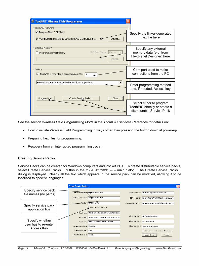
Programming with ToothPIC WFP
ToothPICWFP.exe is used for wireless field programming from Hex data files created by development environments such as MPLAB C18. It can also create Service Packs for Windows and Pocket PC which you can distribute to allow customers and engineers to upgrade firmware themselves.
ToothPICWFP.exe is in the Development Kit. To use it, you will need a Bluetooth-enabled Windows computer. Start the program and a dialog box will appear similar to the one shown below. Program as follows:
1. Specify the hex file you wish to use for programming in the box labeled Firmware.
2. If you have external I2C memory connected to ToothPIC and you wish to program it, specify the hex file in the box labeled External Memory. Select 100kHz or 400kHz clock speed as appropriate for the type of memory used.
FlexiPanel Designer creates external I2C memory hex files if you specify external storage in the user interface.
3. If you have an external host processor connected to ToothPIC and you wish to program it, specify the hex file in the box labeled External Host Processor. Select the host type as appropriate. Ensure that the external host processor is connected for field programming operation.
FlexiPanel Designer creates hex files for BASIC Stamp. Microchip Technology MPLAB products create hex files for PIC products. Specify INHX32 hex file format.
4. Power up ToothPIC with the pushbutton held down. The red and green LEDs will flash simultaneously to indicate that it is ready to be programmed. Press the button again if you want to return to normal operation.
5. Using the Bluetooth software on your computer, search for ToothPIC and make a serial connection to it. The Bluetooth software will tell you which COM port it is using and you should enter the COM port number in the box provided. Specify ‘Enter programming mode at power-up’ for programming method.
6. Press the update button to start programming. The red and green LEDs will flash alternately during programming. The status box will read “Programming succeeded“ when it is finished. ToothPIC will then reset itself and start running the new firmware.
ToothPIC may continue to operate in an ICD-2 debug mode if it was previously doing so.
Page 14 2-May-06 Toothpick 3.0.00009 DS380-8 © FlexiPanel Ltd Patents apply and/or pending www.FlexiPanel.com
See the section Wireless Field Programming Mode in the ToothPIC Services Reference for details on:
• How to initiate Wireless Field Programming in ways other than pressing the button down at power-up.
• Preparing hex files for programming.
• Recovery from an interrupted programming cycle.
Creating Service Packs
Service Packs can be created for Windows computers and Pocket PCs. To create distributable service packs, select Create Service Packs… button in the ToothPICWFP.exe main dialog. The Create Service Packs… dialog is displayed. Nearly all the text which appears in the service pack can be modified, allowing it to be localized to specific languages.
.
Specify the linker-generated hex file here
Enter programming method and, if needed, Access key
Select either to program ToothPIC directly or create a
distributable Service Pack
Specify service pack file names (no paths)
Specify service pack application title
Specify whether user has to re-enter
Access Key
Com port used to make connections from the PC
Specify any external memory data (e.g. from
FlexiPanel Designer) here

Page 15 2-May-06 Toothpick 3.0.00009 DS380-8 © FlexiPanel Ltd Patents apply and/or pending www.FlexiPanel.com
When the Create Now… button is pressed, the “raw” service pack applications SPW.exe (Windows) and SPP.exe (Pocket PC) are copied to the file names you specify and then the hex data is appended on the end in a way that the service packs can read. SPW.exe and SPP.exe are in the Development Kit and must be in the same directory as the Wireless Field Programmer application. The service packs will be created in the same folder as the original firmware .hex file
The service packs applications may be executed on Windows and Pocket PC computers as described in the section Using Service Packs.
Conventional Device Programming
To program ToothPIC using conventional in-circuit programming, pin NMCLR functions as programming pin Vpp, pin INT0 functions as PGD and INT1 functions as PGC.
Service pack About dialog with custom
text (Windows)

Page 16 2-May-06 Toothpick 3.0.00009 DS380-8 © FlexiPanel Ltd Patents apply and/or pending www.FlexiPanel.com
Hello World Bitstream Firmware Solution Description
The Hello World Bitstream firmware solution is a simple tutorial to demonstrate how ToothPIC can be used and programmed for binary communication using Bluetooth.
Hello World Bitstream is straightforward. A Windows PC running HyperTerminal connects to ToothPIC via Bluetooth. (HyperTerminal is a Windows application for sending and receiving ASCII data to and from COM ports such as the Bluetooth COM port.)
As data is typed into HyperTerminal, it is sent to ToothPIC. ToothPIC ignores it unless it is an ‘H’ or a ‘W’. If it is an ‘H’, it replies with the word ‘Hello’. If it is a ‘W’, it replies with the word ‘World’.
Executing the Finished Application
(Throughout this section, use the four zeroes default PIN code 0000 if required.)
Hello World Bitstream is supplied as a Service Pack application which must be ‘Field Programmed’ into ToothPIC. This takes a few seconds and requires either a Windows PC or a Pocket PC with Bluetooth. The procedure is as follows:
1. Select either the HelloWorldBitWin.exe (Windows) or HelloWorldBitPPC.exe (Pocket PC) service pack from the development kit. If necessary, transfer the file to the computer which you will use to Field Program ToothPIC.
2. Power-up the ToothPIC with the on-board pushbutton held down. After initialization, the on-board LEDs will flash simultaneously.
3. Start running the Service Pack and connect from the computer to the ToothPIC using Bluetooth.
4. Enter the COM port used to connect to the ToothPIC in the box provided.
5. Press the Update button. Programming takes about 10 seconds. When the progress bar is full, field programming is complete.
Once loaded, the application will start executing immediately. To experiment with the application, follow these steps:
1. Check the green LED is flashing regularly. This indicates the application is operating correctly.
2. Connect to ToothPIC by creating a Bluetooth serial connection to it from a Windows PC. The red LED will come on when the connection is made.
3. Start Windows HyperTerminal and create a connection using the COM port used to connect to ToothPIC. The baud rate settings will likely be ignored by the computer’s Bluetooth driver, so you can keep the default settings.
4. Type characters into HyperTerminal. Usually nothing will happen except if an ‘H’ or a ‘W’ are typed. the words ‘Hello’ or ‘World’ will then appear respectively.

Page 17 2-May-06 Toothpick 3.0.00009 DS380-8 © FlexiPanel Ltd Patents apply and/or pending www.FlexiPanel.com
Application Development in MPLAB
To examine the code for this application, you will need to be familiar with the Microchip Technology MPLAB development environment and C18 compiler. The MPLAB development environment and C18 compiler must be obtained separately from Microchip Technology Inc or one of its distributors.
A debugger or programmer will also be required. For product development, the Microchip ICD-2 in-circuit debugger is recommended. For programming, the following connections must be made between the ICD2 debugger and ToothPIC
Pin name on ToothPIC Name in MicroChip’s Terminology Vss Vss Vdd Vdd
NMCLR NMCLR INT0/PGC PGC INT1/PGD PGD
The cable from the debugger to the ToothPIC needs to be short. An adapter cable is available for connecting directly from the ICD2 to a ToothPIC plugged into a breadboard – see the Ordering Information section.
The following steps explain how to create the MPLAB project from scratch. You can alternatively load the project HelloWorldBit.mcw (found in the Development Kit) into MPLAB
1. Create a project named in MPLAB with the following characteristics:
• Device PIC18F6720 • HS oscillator configuration • Watchdog timer off • Watchdog timer postscaler 1:128 • Power-up timer on • Oscillator switch enabled • CCP2 Mux RE7 • Table Write Protect 00200-03FFF enabled • Table Write Protect 04000-08FFF enabled • Table Write Protect 08000-0BFFF enabled • Table Write Protect 00000-001FF enabled • Large Code Model • Large Data Model • Multi-Bank Stack Model
If you forget any of these, the project will still compile, but it won’t run correctly. Note, in particular, the last three items may result in behavior that seems right at first but may later behave unexpectedly, making debugging difficult. Please check these have been set before calling technical support.
2. Copy the following files from the Development Kit directory to your project directory and include them in the project:
• ToothPIC.h, the ToothPIC Services header file in the development kit main directory. • ToothPicMath304.o, the ToothPIC math libraries object file in the development kit main
directory. • ToothPIC304.lib, the ToothPIC Services library in the development kit main directory. • ToothPIC304.lkr, the ToothPIC linker script in the development kit main directory.
The above files contain the information about ToothPIC Services and are included in all applications. They do not need to be modified from their original form.

Page 18 2-May-06 Toothpick 3.0.00009 DS380-8 © FlexiPanel Ltd Patents apply and/or pending www.FlexiPanel.com
3. Open the file ToothPIC303.c in development kit main directory and save it in your project directory. This file allows you to customize the ToothPIC Services for this specific application. In this case the only modification required is to change the device name. Replace the line:
rom unsigned char pLocalName[LOCALNAMELEN] = "ToothPIC 3.0";
with the line:
rom unsigned char pLocalName[LOCALNAMELEN] = "Hello World Bit";
Note the many other settings in the file: PIN codes, device classes, etc. You can modify the values but it is very important that you do not modify the order or the size of these variable declarations. This is because during Wireless Field Programming, your application code gets updated but the ToothPIC Services do not.
4. Open the file Main.c which is in the development kit main directory and save it in your project directory with the name HelloWorldBit.c. This file is an ‘empty shell’ main application containing all the functions you need to provide code for in your application. The ‘empty shell’ simply flashes LEDs to indicate whether or not it is functioning correctly. Note how it contains a main function which initializes and then runs in an infinite loop. The functions HighInterrupt, LowInterrupt, ErrorStatus, BMTEvent and FxPEvent are ‘callbacks’ which are called by ToothPIC services when certain events occur. For example, the LowInterrupt is called once per second with the interrupt flag SWI_Tick set. Main.c clears the flag – if it did not, ToothPIC would keep calling LowInterrupt because it would assume that the interrupt had not yet been serviced.
5. The first change to be made to HelloWorldBit.c is to tell the BlueMatik radio to enter slave mode so other devices can connect to it. Since this will also be necessary after each disconnection, the static variable InSlaveMode will keep track of whether the slave mode command needs to be send. Place the following line at the beginning of the file before the main declaration:
Bool InSlaveMode = False; // false if we need to send a BMTC_Slave command
and insert the following code inside the infinite loop of the main function:
if (!InSlaveMode) { BMTCommand( BMTC_Slave, 0, 0 ); // Start BlueMatik binary service AwaitBMTOK; InSlaveMode = True; }
This will put the radio in slave mode whenever the flag InSlaveMode is not set.
6. If a remote device connects to ToothPIC and then disconnects, ToothPIC will no longer be in slave mode, so it needs to be put back into slave mode again. To do this, a BMTE_Disco message is sent to the BMTEvent callback when the remote device disconnects. At the same time, we will trap the BMTE_Connect message and light the red LED when a remote device is connected. Add the following code to the BMTEvent callback function:
if ( EventID==BMTE_Connect ) { // turn on red led during connection LedRed = LedRedOn; } if ( EventID==BMTE_Disco ) { // turn off red led after disconnection LedRed = LedRedOff; // re-enter slave mode

Page 19 2-May-06 Toothpick 3.0.00009 DS380-8 © FlexiPanel Ltd Patents apply and/or pending www.FlexiPanel.com
InSlaveMode = False; }
Note how the InSlaveMode ‘semaphore’ is set inside the interrupt and slave mode is re-entered from the main loop. This is because functions which require a response from BlueMatik (such as AwaitBMTOK in this case) will only process that response in an interrupt. If you don’t leave this interrupt first, the response will never be processed. (See the section on Semaphores for more details.)
7. Finally, add the code which sends the text Hello and World when the H and W characters are received. Add the following lines at the beginning of the file before the main declaration:
rom unsigned char * szHello = "Hello\r\n"; rom unsigned char * szWorld = "World\r\n";
When data is received from the remote device, it is put in the receive buffer and then the LowInterrupt callback is called with the flag SWI_BMTData set. Add the following code to process the interrupt:
if (IsSWI( SWI_BMTData ) ) { unsigned char ch = *BMTRxCh; // if the received character is an 'H', say hello if (ch=='h' || ch=='H') { BMTTransmit( szHello, 0, 7, 255 ); } // if the received character is an 'W', say world if (ch=='w' || ch=='W') { BMTTransmit( szWorld, 0, 7, 255 ); } // remove the character from the receive buffer BMTRxAdvanceCh; ClearSWI( SWI_BMTData ); // Clear interrupt flag return; }
This code transmits Hello or World as you would expect, but also does two other things. First, it calls the macro BMTRxAdvanceCh which removes the character from the receive buffer after it has been processed (or ignored). Second, it clears the software interrupt flag SWI_BMTData.
The application should now function correctly. Compile it and load it into ToothPIC. By setting breakpoints in a debugger, you can trap events to see the code being processed. Remember that if you are stopped at a breakpoint, ToothPIC will no longer process information coming from BlueMatik.

Page 20 2-May-06 Toothpick 3.0.00009 DS380-8 © FlexiPanel Ltd Patents apply and/or pending www.FlexiPanel.com
Hello World FlexiPanel Firmware Solution Description
The Hello World FlexiPanel firmware solution is a simple tutorial to demonstrate how ToothPIC can be used and programmed for use with FlexiPanel User Interface services. It is assumed that you have completed the Hello World Bitstream tutorial.
Hello World FlexiPanel is straightforward. It provides a user interface with a button and a message text area. The message text will initially say Hello. When you press the button, the text toggles between Hello and World.
Executing the Finished Application
(Throughout this section, use the four zeroes default PIN code 0000 if required.)
Hello World FlexiPanel is supplied as a Service Pack application which must be ‘Field Programmed’ into ToothPIC. This takes a few seconds and requires either a Windows PC or a Pocket PC with Bluetooth. The procedure is as follows:
1. Select either the HelloWorldFxPWin.exe (Windows) or HelloWorldFxPPPC.exe (Pocket PC) service pack from the development kit. If necessary, transfer the file to the computer which you will use to Field Program ToothPIC.
2. Power-up the ToothPIC with the on-board pushbutton held down. After initialization, the on-board LEDs will flash simultaneously.
3. Start running the Service Pack and connect from the computer to the ToothPIC using Bluetooth.
4. Enter the COM port used to connect to the ToothPIC in the box provided.
5. Press the Update button. Programming takes about 10 seconds. When the progress bar is full, field programming is complete.
Once loaded, the application will start executing immediately. To experiment with the application, follow these steps:
5. Download from www.FlexiPanel.com FlexiPanel Client software for Windows, Pocket PC, Smartphone or Java phone. Install as required.
6. Check the green LED on ToothPIC is flashing regularly. This indicates the application is operating correctly.
7. Connect to ToothPIC from the FlexiPanel Client as described in the instructions for the client. The red LED will come on when the connection is made and the button and text box user interface will appear on the FlexiPanel client.
8. Press the Change Text to change between the Hello

Page 21 2-May-06 Toothpick 3.0.00009 DS380-8 © FlexiPanel Ltd Patents apply and/or pending www.FlexiPanel.com
and World texts. The application won’t win any beauty contests, but as a tutorial it must be kept simple. Clickable image controls produce the ‘coolest’ user interfaces if you have the time to develop appropriate graphics for the application.
User Interface Development in FlexiPanel Designer
Before developing the application in MPLAB, create the user interface in FlexiPanel Designer. It is good practice to do this first as the result is a more user-friendly application. The following steps create the user interface:
1. Download FlexiPanel Designer from www.FlexiPanel.com and start the application.
2. In the Target Device menu, set the target device to ToothPIC.
3. In the Insert menu, select Insert Control > Insert Text. You have created a text control. By default it is fixed, meaning the user cannot modify it, and has a maximum of 16 characters. In the properties list box on the right, change the Control Properties > Data Storage type to RAM. This is because we will be modifying the contents frequently and we don’t care if the value is lost if power is removed. In the same properties list, change the Initial text to Hello. Note the variety of controls which are possible – right up to sophisticated controls such as matrices (charts) and images.
4. In the Insert menu, select Insert Control > Insert Button. You have created a button control. In the properties list box on the right, change the Control Properties > Title to Change Text. Note how the controls you have created are displayed in the list in the central section of the screen. The Control Name is how you will refer to controls in your application code; the ID value it creates is how ToothPIC services refers to controls internally.
5. The controls have been ‘logically’ defined. If you stopped at this stage, the controls would be perfectly useable on any FlexiPanel client device. However, you may wish to improve the layout on certain platforms such as Windows and Pocket PC. In the properties list box on the right, select Pocket PC properties. The screen appearance will change to show the layout of controls of the Pocket PC. Drag the controls as shown in the following diagrams. (Click on the + to move a control and the arrow to resize it.)

Page 22 2-May-06 Toothpick 3.0.00009 DS380-8 © FlexiPanel Ltd Patents apply and/or pending www.FlexiPanel.com
Before After
The Prev, Next and First navigations are not needed because all the controls fit in a single screen. That is why they have been dragged off-screen and thus out of view. The other controls have been repositioned.
6. The text control is large so the font size need so be increased. Select the control by clicking on it so that it turns blue. Then in the properties list on the right, make the following changes / checks:
Font bold Yes Font size 40 Height Check it’s at least 51 Justify Center Show Border Yes Width Check it’s at least 181
7. In the properties list box on the right, select Windows properties and then set the Screen Height property to 300 and the Screen Width property to 240. Drag the controls and modify the text control as before. (There are no navigation or close buttons in the Windows Client.)
Before After
8. In the properties list box on the right, select FlexiPanel Server properties and then set the Device Name to Hello World FxP. Note the Force Layout option. Keep this set to Yes during development so that FlexiPanel Clients always read the latest user interface layout information. Change it to No for production to stop FlexiPanel Designer appending a unique number to the end of the Device Name. (It has to do this in order to tell the Clients to reload user interface data.)

Page 23 2-May-06 Toothpick 3.0.00009 DS380-8 © FlexiPanel Ltd Patents apply and/or pending www.FlexiPanel.com
9. Save the file as HelloWorldFxPRes.FxP in the project directory for this application. The Res at the end of the filename is generally used to indicate that it, and the files it creates, contain user interface resources.
10. In the Target Device menu, select Create C Code... FlexiPanel Designer will create a HelloWorldRes.h header file and a HelloWorldRes.c source code file which you should save in the project directory. The C code contains the user interface data to be stored in ToothPIC program memory. (You may need to change the #include “ToothPIC.h” path if the file is not in the same directory as your project.) The header file contains computer-generated macros to make it easier to access the controls from your application code.
11. The user interface is now complete. Note that one of the Target Devices you can select is Simulation. This allows you to test user interfaces directly from within FlexiPanel Designer. The aim of this tutorial has not been to produce the most aesthetically pleasing user interface, and you can see there is plenty of scope for improvement, particularly if image controls are used.
Application Development in MPLAB
The following steps explain how to create the MPLAB project from scratch. You can alternatively simply load the project HelloWorldBit.mcw (found in the Development Kit) into MPLAB
1. Create a project named in MPLAB with the following characteristics:
• Device PIC18F6720 • HS oscillator configuration • Watchdog timer off • Watchdog timer postscaler 1:128 • Power-up timer on • Oscillator switch enabled • CCP2 Mux RE7 • Table Write Protect 00200-03FFF enabled • Table Write Protect 04000-08FFF enabled • Table Write Protect 08000-0BFFF enabled • Table Write Protect 00000-001FF enabled • Large Code Model • Large Data Model • Multi-Bank Stack Model
If you forget any of these, the project will still compile, but it won’t run correctly. Note, in particular, the last three items may result in behavior that seems right at first but may later behave unexpectedly, making debugging difficult. Please check these have been set before calling technical support.
2. Copy the following files from the Development Kit directory to your project directory and include them in the project:
• ToothPIC.h, the ToothPIC Services header file in the development kit main directory. • ToothPicMath304.o, the ToothPIC math libraries object file in the development kit main
directory. • ToothPIC304.lib, the ToothPIC Services library in the development kit main directory. • ToothPIC304.lkr, the ToothPIC linker script in the development kit main directory.
The above files contain the information about ToothPIC Services and are included in all applications. They do not need to be modified from their original form.
3. Also include in the project the files HelloWorldRes.h and HelloWorldRes.c, generated by FlexiPanel Designer. The C code contains the user interface data to be stored in ToothPIC program

Page 24 2-May-06 Toothpick 3.0.00009 DS380-8 © FlexiPanel Ltd Patents apply and/or pending www.FlexiPanel.com
memory. The header file contains computer-generated macros to make it easier to access the controls from your application code.
4. Open the file ToothPIC303.c in the development kit main directory and save it in your project directory. This file allows you to customize the ToothPIC Services for this specific application. In this case the only modification required is to change the device name. At the beginning of the file, #include the file HelloWorldRes.h created by FlexiPanel Designer. The code will then begin as follows:
#define __ToothPIC_c__ #include "ToothPIC.h" #include <p18f6720.h> // If programming a FlexiPanel UI from FlexiPanel Designer using data files, // include the header file Designer creates, (comment out otherwise) #include "HelloWorldRes.h"
5. Open the file Main.c development kit main directory and save it in your project directory with the name HelloWorldFxP.c. This file is an ‘empty shell’ main application containing all the functions you need to provide code for in your application. At the beginning of the file, #include the file HelloWorldRes.h created by FlexiPanel Designer. Also create static text variables for the words “Hello and World, so that the code begins as follows:
#include "ToothPIC.h" #include <p18f6720.h> #include "HelloWorldRes.h" rom unsigned char * szHello = "Hello\r\n"; rom unsigned char * szWorld = "World\r\n";
6. During initialization, the FlexiPanel User Interface server must be started. Unlike regular BlueMatik
slave mode, this does not need to be re-started each time a device disconnects so the code is simpler. Place the following lines immediately prior to the start of the infinite look in the main function:
FxPCommand( FxPC_Start, 0, 0 ); // Start FlexiPanel service AwaitBMTOK; // Service operating, no client
7. Events that happen to the FlexiPanel server are reported in the FxPEvent callback. Add the following lines to the callback function so that the red LED comes on when a verified client connects:
if ( EventID==FxPE_Connect ) { // turn off red led during connection LedRed = LedRedOn; } if ( EventID==FxPE_Disco ) { // turn off red led after disconnection LedRed = LedRedOff;
}
8. Finally, code must be added to process the event when the ChangeText button is pressed. Add the following lines to the callback function:
// Check for control events if ( EventID==FxPE_ClntUpdate ) { // If the button was pressed... if (*((unsigned short*) pData) == ID_Change_Text_2) { // Is the current text value Hello or World? if (pText1_1[0] == 'H') { // set the text value to World and update the client

Page 25 2-May-06 Toothpick 3.0.00009 DS380-8 © FlexiPanel Ltd Patents apply and/or pending www.FlexiPanel.com
SetUp_Text1_1( szWorld, 0 ) ; } else { // set the text value to Hello and update the client SetUp_Text1_1( szHello, 0 ) ; } } }
Many macros from HelloWorldRes.h were used in this last piece of code. The macros generated will depend on the control types and where the data is stored. Inspect the file HelloWorldRes.h to see the macros available for the controls you have created. In particular, note the following:
• The FxPE_ClntUpdate event signals that a control has been modified by the user.
• The ID_Change_Text_2 ID value, defined in HelloWorldRes.h, is used to identify that the Change Text button has been modified. The _xxx suffix (_2 in this case) is added to ensure all control ID definitions are unique even if their title is the same. The ID value definitions such as ID_Change_Text_2 will not change (so long as you do not change the control title), although the underlying ID values will as you add and remove controls from the user interface.
• The pText1_1 pointer, defined in HelloWorldRes.h, may be used to access the control data. In this case, because the pointer is a RAM pointer, you can use it for reading or writing the value. If it was a ROM pointer, you could use it for reading only. If the control was stored in external memory, no pointer would be defined at all. Set_ and Get_ macros are defined for all controls and you can always access the control values using those macros.
• The SetUp_Text1_1 macro, defined in HelloWorldRes.h, is used to set the value of the control and then send the updated value to the remote client. It has two arguments - the first is if the source data is a ROM pointer, the second is if the source data is a RAM pointer. The unused argument must be set to zero.
The application should now function correctly. Compile it and load it into ToothPIC. By setting breakpoints in a debugger, you can trap events to see the code being processed. Remember that if you are stopped at a breakpoint, ToothPIC will no longer process information coming from BlueMatik. With FlexiPanel service in operation, you may wish to turn off pings if they are enabled on the Client to stop it sending ping messages while ToothPIC is at a breakpoint.

Page 26 2-May-06 Toothpick 3.0.00009 DS380-8 © FlexiPanel Ltd Patents apply and/or pending www.FlexiPanel.com
BlueMatik Diagnostic Firmware Solution This section assumes you have followed the Hello World Firmware Solution tutorials.
Description
The BlueMatik Diagnostic firmware solution is what we use to re-test the low-level ToothPIC Services communication with the BlueMatik radio module. The source code also provides good examples of how to use these low-level ToothPIC Services.
BlueMatik Diagnostic runs tests by communicating with its partner application, BlueMatikTestWin.exe, which must be run on a Windows computer. The source code for the BlueMatikTestWin.exe is included in the development kit but is not discussed in great detail here. For more in-depth source code for remote devices connecting to FlexiPanel Ltd’s Bluetooth products, consult the documentation for our BlueMatik and/or LinkMatik products.
BlueMatik Diagnostic checks master and slave connections, security, device enquiry, bulk data transfer, link quality and signal strength. Please note that failure to complete these diagnostic tests does not necessarily mean that ToothPIC is not functioning correctly; the fault may lie elsewhere. In particular, take care to verify the COM ports and security settings of the Bluetooth driver on the Windows PC.
Executing the Finished Application
BlueMatik Diagnostic is supplied as a Service Pack application which must be ‘Field Programmed’ into ToothPIC. This takes a few seconds and requires either a Windows PC or a Pocket PC with Bluetooth. The procedure is as follows:
1. Select either the BlueMatikTestSPWin.exe (Windows) or BlueMatikTestSPPPC.exe (Pocket PC) service pack from the development kit. If necessary, transfer the file to the computer which you’ll use for Field Programming.
2. Power-up the ToothPIC with the on-board pushbutton held down. After initialization, the on-board LEDs will flash simultaneously.
3. Start running the Service Pack and connect from the computer to the ToothPIC using Bluetooth, using the PIN code 0000 if required.
4. Enter the COM port used to connect to the ToothPIC in the box provided.
5. Press the Update button. Programming takes about 10 seconds. When the progress bar is full, field programming is complete.
Once loaded, the application will start executing immediately. To experiment with the application, follow these steps:
6. Start running BlueMatikTestPC.exe on the Windows PC and enter the outgoing and incoming COM port numbers as prompted.
7. When prompted, and not before, make a serial Bluetooth connection from the Windows PC to ToothPIC.

Page 27 2-May-06 Toothpick 3.0.00009 DS380-8 © FlexiPanel Ltd Patents apply and/or pending www.FlexiPanel.com
8. The remainder of the test is automatic and should end with the message ToothPIC test SUCCEEDED.
Application Development in MPLAB
The application code for ToothPIC firmware solution is relatively simple. Both the MPLAB (ToothPIC) and Visual C++ (Windows) projects are available for inspection in the development kit. The most important ToothPIC file is the application source code file BlueMatikTest.c. The corresponding Windows file is BlueMatikTestWin.cpp. The key features of the source code are discussed below.
Connection Testing and Device Enquiry
First, the Windows computer creates a connection without security. Then ToothPIC creates a connection by exchanging PIN codes and becomes ‘trusted’ (a.k.a. ‘paired’ or ‘bonded’). The user will be prompted for the PIN code and 0000 must be entered. Then it disconnects and tries to connect to a Bluetooth address that doesn’t exist, giving up after 5 seconds. The reason for this test is to check that failure to connect generates no problems. Then ToothPIC performs a device enquiry for 10 seconds and stores the device names found.
Data Transfer
ToothPIC then reconnects to the Windows computer. This time the devices are paired so it can connect without asking for the PIN again. First it reports the Bluetooth devices found. Then it measures the transfer time for 100kbits of data first in one direction then the other. This is not just to measure transfer rates but also to verify that data is not corrupted or lost due to handshaking errors.
Signal Strength Measurement
Finally, ToothPIC sends the Link Quality and Signal Strength commands to verify that they both function correctly. Due to the automatic gain control of the radio, these statistics really only provide an indication of signal quality when the quality is poor.

Page 28 2-May-06 Toothpick 3.0.00009 DS380-8 © FlexiPanel Ltd Patents apply and/or pending www.FlexiPanel.com
ToothPIC Diagnostic Firmware Solution This section assumes you have followed the Hello World Firmware Solution tutorials.
Description
The ToothPIC Diagnostic firmware solution is what we use to re-test the high-level ToothPIC Services when we make changes to them. The source code also provides good examples of how to use the ToothPIC Services and FlexiPanel controls.
ToothPIC Diagnostic is a multi-dialog application, with each dialog testing a different set of functions. We have included some ‘placeholder’ dialog pages for services we expect to add in product updates. For the moment, these dialogs are not functional.
Executing the Finished Application
ToothPIC Diagnostic is supplied as a Service Pack application which must be ‘Field Programmed’ into ToothPIC. This takes a few seconds and requires either a Windows PC or a Pocket PC with Bluetooth. The procedure is as follows:
1. Select either the ToothPICTestWin.exe (Windows) or ToothPICTestPPC.exe (Pocket PC) service pack from the development kit. If necessary, transfer the file to the computer which you will use to Field Program ToothPIC.
2. Power-up the ToothPIC with the on-board pushbutton held down. After initialization, the on-board LEDs will flash simultaneously.
3. Start running the Service Pack and connect from the computer to the ToothPIC using Bluetooth.
4. Enter the COM port used to connect to the ToothPIC in the box provided.
5. Press the Update button. Programming takes about 30 seconds. When the progress bar is full, field programming is complete.
Once loaded, the application will start executing immediately. To experiment with the application, follow these steps:
6. If you have not already done so, download from www.FlexiPanel.com FlexiPanel Client software for Windows, Pocket PC, Smartphone or Java phone. Install as required.
7. Check the green LED on ToothPIC is flashing regularly. This indicates the application is operating correctly.
8. Connect to ToothPIC from the FlexiPanel Client as described in the instructions for the client. The red LED will come on when the connection is made and the Choose Test Dialog will appear on the FlexiPanel client. The controls are transmitted before the formatting information, so the first time you connect, the controls may look a bit odd for a couple of seconds.
9. Select Real Time Clock from the Choose Test list and press Run Test. You can set the real time clock time and date using the editable date-time controls. When you do so, the fixed time control and

Page 29 2-May-06 Toothpick 3.0.00009 DS380-8 © FlexiPanel Ltd Patents apply and/or pending www.FlexiPanel.com
the day-of-week calculation will be updated. You can also change the Daylight Savings Time rules and, if the appropriate time is set, watch the date and time advance or retard. (See the Real Time Clock section of the ToothPIC Services Reference for exact details of when the clock changes.) The Refresh SecFrac button and the modifiable number control below it allow you to read and write the 1/32768ths of a second. Press End Test when you have finished this test and each of the following tests.
10. Select Analog to Digital from the Choose Test list and press Run Test. Select which input to measure and see the result in the voltage display. If the pins are unconnected, you will be measuring stray voltages which are liable to fluctuate.
11. Make sure the I/O pins are unconnected. Then select Test Digital Outputs from the Choose Test list and press Run Test. Press the latching buttons to set the outputs high or low and use a multimeter to check the voltages. (SDA and SDO will not work because these pins are configured for I2C.)
12. Select Test Digital Inputs from the Choose Test list and press Run Test. A red background color indicates the input is ‘high’ and gray indicates the input is ‘low’. If the pins are unconnected, you will be measuring stray voltages which will fluctuate.
13. Make sure the I/O pins are unconnected. Then select Test Parallel Outputs from the Choose Test list and press Run Test. These are the same as the regular digital outputs except the values change simultaneously. This is useful when transmitting parallel data or if you need to tie several outputs together to drive loads greater than 25mA.
14. Select Test Parallel Inputs from the Choose Test list and press Run Test. These are the same as the regular digital inputs except the values are measured simultaneously.
15. Select LED + Pushbutton Test from the Choose Test list and press Run Test. You can control the LEDs and make various message boxes appear by pressing the ToothPIC pushbutton.
16. Select Memory test from the Choose Test list and press Run Test. Read and write to memory. Note that if no external memory is connected, you will get a memory failure error if you try and read or write to it. Also, don’t write to a memory location unless you are sure that ToothPIC isn’t using it!
17. Select Slider & Progress Bar from the Choose Test list and press Run Test. When you move the slider, the progress bar moves. These controls are not available on all clients and you may find that all you see are a modifiable and a non-modifiable number

Page 30 2-May-06 Toothpick 3.0.00009 DS380-8 © FlexiPanel Ltd Patents apply and/or pending www.FlexiPanel.com
control instead.
18. Select Miscellaneous Controls from the Choose Test list and press Run Test. If you press Go to URL and the computer you are using is web-enabled, you will be taken to www.FlexiPanel.com. If you press Display File, ToothPIC will upload two web pages stored internally – all you need is a web browser to see these pages. However, If you have many web pages, you may need to add external memory.
19. Two identical image controls with the FlexiPanel logo are displayed. The first on the left displays a message when you click on it. The second uses ‘overlay’ storage type, so it actually uses the same source data as the other image control. This is very useful if you use the same image in several dialogs of your user interface. If you have many images, you may need to add external memory.
20. Enter the password 1234 in the password control. This makes the List, XY, Labels and Time section controls appear.
21. Press List Section to see the List-style matrix control depicted as a table. This is useful for matrix data which doesn’t really have an X-axis. Press List Section again to return to the main Miscellaneous Controls dialog (and for the other matrix controls, too.)
22. Press List Section to see the List style control depicted as a table. This is useful for matrix data which doesn’t really have an X-axis. Press List Section again to return to the main Miscellaneous Controls dialog (and for the other matrix controls, too.).
23. Press Labels Section to see the Labels matrix control depicted as a column chart. This is useful for matrix data which has a category-style X-axis. On some clients, you can click on the chart to zoom it up, see a table of values or save the data to a file.
24. Press XY Section to see the XY style control depicted as a points chart. This is useful for matrix data which has a numerical X-axis. On some clients, you can click on the chart to zoom it up, see a table of values or save the data to a file.
25. Press Time Section to see the Date-Time matrix control depicted as a line chart. This is useful for matrix data which has a time-style X-axis. Note how a new value is appended to the chart every five seconds. On some clients, you can click on the chart to zoom it up, see a table of values or save the data to a file.

Page 31 2-May-06 Toothpick 3.0.00009 DS380-8 © FlexiPanel Ltd Patents apply and/or pending www.FlexiPanel.com
User Interface Development in FlexiPanel Designer
If you open the file ToothPICTestRes.FxP in FlexiPanel Designer, you will see that this user interface has over 160 controls spread over 15 dialogs. Note how all the dialogs are all in one list and the boundary between dialogs is indicated by the indentation of the control name in the list. A new dialog is created simply by creating the first control in the dialog and then specifying Yes for its New Dialog property.
Note also the properties list for the image control as depicted in the graphic below. The graphic, which must be in GIF format, is loaded in by double-clicking on the Image Data control. In the individual client layout settings, you can choose to stretch or tile it as required. This is useful for using images for backgrounds, etc. The Data Storage is set to Overlay and the Data Overlay Control is set to the other image control. This means that the control will use the same storage location as the other image control.
Application Development in MPLAB
The application code for the ToothPIC Diagnostic firmware solution is extensive and the entire project is available for inspection in the development kit. The most important files to note are the application source code file ToothPICTest.c and the Designer-generated macros header file ToothPICTestRes.h. The key features of the source code are discussed below.
Initialization
When the application starts, the external memory is initialized, the FlexiPanel server is initialized and the list, labels and XY matrix controls are initialized with data. Note how the pRowCounter_ pointer macro is used to set the number of rows of the matrix which are displayed.

Page 32 2-May-06 Toothpick 3.0.00009 DS380-8 © FlexiPanel Ltd Patents apply and/or pending www.FlexiPanel.com
Main Program Loop
In the main program loop, the green LED is flashed every 250ms, provided the LED test is not running. If the test to be run is one of the analog or digital input tests, the input value is read and the relevant control is updated.
High Interrupt
No high priority interrupts are expected nor provided for.
Low Interrupt
Two types of low priority interrupts are expected: when the clock ticks and when the pushbutton is pressed.
Every second, a SWI_Tick software interrupt will be received. When it is, the controls in the Real Time Clock dialog are updated. Note that the DT_Edit_8 modifiable Date-Time control does not require updating because in FlexiPanel Designer it was specified as ‘linked’ to the Real Time Clock. This means that ToothPIC automatically updates it when the clock ticks and conversely updates the Real Time Clock if the user modifies the control. Every five seconds, a row of data is appended to the time matrix control. Note how the FxPC_PartUpdate command is used rather than the FxPC_Update command to send the new data to the client. This saves ToothPIC from having to resend the entire matrix – it just sends the new row of data instead.
When the pushbutton is pressed, the appropriate message box is displayed. If a response is expected, this is processed elsewhere – in the FxPEvent callback.
In both cases, the final step is to clear the interrupt flag. If the flag is cleared earlier, it allows another low priority interrupt to occur. While this is possible, great care needs to be exercised to avoid stack overflow.
ErrorStatus and BMTEvent
No errors are expected. However, it is always possible that ToothPIC will enter an unanticipated state and generate an error. During development, it is best to set a breakpoint so we can inspect what caused the error. For product release, it is obviously better to enter a failsafe state and/or reset.
FlexiPanel Server Events
If a client connects or disconnects, the red LED is updated accordingly. If the close button is pressed, ToothPIC disconnects from the client.
If the Run Test button is pressed, the FxPC_SetDialog command is used to show the appropriate dialog to the test and the analog or digital I/O pins and pushbutton interrupt are configured as needed. If the test requires sampling the inputs regularly, the MSF_TestsRunning semaphore is raised so that the tests are run in the main program loop. If any End Test button is pressed, ToothPIC returns to the Choose Test dialog.
Real Time Clock Dialog: If the date is changed, ToothPIC recalculates the day of week; if the daylight savings time or summer time controls are changed, the real time clock’s daylight savings time event is updated; if the seconds fraction controls are operated, ToothPIC retrieves or sets the time as appropriate.
Digital Outputs / Parallel Outputs / LED Test Dialogs: If any of the controls are changed, the outputs are changed accordingly.
Memory test: If any of the Set Value or Get Value buttons are pressed, the memory location is retrieved or modified.
Slider & progress test: If the slider control is adjusted, the progress control is updated. Note that the value does not need to be copied from the slider to the progress control since they use the same storage locations.

Page 33 2-May-06 Toothpick 3.0.00009 DS380-8 © FlexiPanel Ltd Patents apply and/or pending www.FlexiPanel.com
Miscellaneous Ctls: If the image control is clicked, a message is displayed. Note that the password and section controls are handled automatically by ToothPIC Services.
Finally, if a message box was created by pressing the ToothPIC button, a FxPE_MsgResp may be generated when one of its response buttons is pressed. The button number is displayed in a number control.

Page 34 2-May-06 Toothpick 3.0.00009 DS380-8 © FlexiPanel Ltd Patents apply and/or pending www.FlexiPanel.com
DARC-I Firmware Solution The DARC-I Firmware Solution allows ToothPIC to operate as a standalone Data Acquisition and Remote Control (DARC) device. It is controlled by a remote device, using the Bluetooth link, using a simple set of serial commands. No development is required on the ToothPIC.
Description
DARC-I is an example of a Data Acquisition and Remote Control application using ToothPIC. I/O is configured from the Remote Device. The basic commands, which may be sent in binary or ASCII hexadecimal format, are:
Command Summary Command Effect Reset Disconnects and resets Configure DARC-I Configures DARC-I (security, log rates, PWM, A/D, clock…) Configure I/O Configures I/O Set I/O Sets an I/O value Get I/O Requests an I/O value Read Memory Reads from memory locations Write Memory Writes to memory locations Stream Data Streams data samples to remote device Get Data Frame Stores a sequence of data samples in memory at higher speeds Log Data Logs data records to memory at specific times.
The DARC-I Firmware Solution will be sufficient for basic data acquisition, logging and remote control. For customized applications, the DARC-I Firmware Solution may be used as proof-of-principle. Later, the C source code can be modified to achieve specific goals such as power saving modes or faster data acquisition. Very often the changes required for customizing DARC-I are simple and it will probably make more sense for FlexiPanel Ltd to make these changes for you if you are not familiar with the MPLAB development environment.
Executing the Evaluation Version
The DARC-I Evaluation Version is a fully documented commercial product. The documentation is included in the development kit as the file DARC-I.pdf. Follow the instructions in that documentation to execute and explore the product.
The documentation is of interest in itself because it gives an indication of important elements which should be included in commercial products using DARC-I. In particular, note:
• Patents apply and/or pending – all products incorporating ToothPIC are implicitly protected by FlexiPanel’s patents and patent applications.
• Field-Programming Instructions – demonstrating this advanced feature of the product which relieves you of the need to manage multiple product lines each with different firmware.
• Antenna position guidance. • Current requirements – since peak current requirement is relatively high. • FCC / CE / IC Modular Approval – device labeling requirements.
Customization in MPLAB
If you wish to customize the DARC-I module, you will need to modify it using the MPLAB development environment. If you have not already done so, please study the Hello World applications.

Page 35 2-May-06 Toothpick 3.0.00009 DS380-8 © FlexiPanel Ltd Patents apply and/or pending www.FlexiPanel.com
The application code for the ToothPIC DARC-I firmware solution is extensive and the entire project is available for inspection in the development kit. The most important file to note is the application source code file DARC-I.c. The key features of the source code are discussed below.
Static Declarations
ROM and RAM spaces provided for the user are reserved using static variables such as pFxPRAM000 and p010000. This prevents the linker from using them for other purposes. The sample record array record is declared statically for storing one record of data since this is faster than allocating it dynamically on the stack.
Initialization
When the application starts, settings are read from ROM and static variables are initialized. Then external memory and security settings are enabled as required. Finally, both LEDs are flashed to provide visual confirmation that the module is running.
Main Program Loop
The main program loop does nothing except put the BlueMatik module into slave mode if the application has just initialized or if a remote device disconnects.
High Interrupt
No high priority interrupts are provided for. The only high priority interrupt expected is data from BlueMatik, and ToothPIC Services manages that automatically.
Low Interrupt
Several types of low priority interrupts are expected:
• When timer 4 overflows, which it may be configured to do every 200µs. . • When the real time clock ticks each second. • When the BlueMatik receive buffer has received a new byte. • When a software interrupt is raised to indicate that a complete command is awaiting processing.
When timer 4 overflows, the interrupt flag is immediately cleared. This allows the timer to interrupt again when the next overflow occurs. This is not normally regarded as good practice since it is difficult to plan for multiple interrupts making the stack overflow. However, in this case, we next detect whether a second interrupt has been received while the previous one is still being processed; if it has, the ‘overflow’ error semaphore is set and the timer is disabled. The interrupt processing routine then decrements a countdown clock and, when it reaches zero, takes samples and stores or streams the data as necessary.
Every second, a SWI_Tick software interrupt will be received. When it is, the real time clock is compared to the LogRate variable and, if due, a sample is taken and stored in memory.
When the BlueMatik receive buffer is updated, DARC-I first checks whether streaming is in process. If it is, it will be interpreted as the instruction to stop streaming. Otherwise, it is interpreted as a partial or complete command and is inspected for obvious errors. If there are any, or all the bytes of a command have been received, a software interrupt is raised to process the command.
When the software interrupt is raised indicating that a complete command is awaiting processing, it is processed as appropriate.
ErrorStatus
No errors are expected. If an error occurs, the auxiliary function InternalError() performs whatever task is supposed to be performed in the event of an error.
Page 36 2-May-06 Toothpick 3.0.00009 DS380-8 © FlexiPanel Ltd Patents apply and/or pending www.FlexiPanel.com
BMTEvent
Errors are handled in the same way as for ErrorStatus. If a device connects, the initialization message is sent. If a device disconnects a flag is raised to tell the main program loop to re-enter BlueMatik slave mode.
FlexiPanel Server Events
The FlexiPanel User Interface server is not used.
Command Processing Functions
7 command processing functions are provided:
• ConfigDarcCmd() for processing Configure DARC-I commands. • ConfigIOCmd() for processing Configure I/O commands. • SetIOCmd() for processing Set I/O commands. • GetIOCmd() for processing Get I/O commands. • GetMemCmd() for processing Get Memory commands. • GetMemCmd() for processing Set Memory commands. • StreamFrameCmd() for processing Stream and Frame commands.
While these functions are extensive, their functions are self-evident.
Auxiliary Functions
Auxiliary functions are provided for:
• Signaling an error. • Sending responses to the remote device in binary or ASCII. • Converting from ASCII to binary and vice versa. • Including and excluding inputs from the sample record set. • Analog to digital conversion. • Deciding where to store the next sample record in memory. • Measuring inputs and storing the result in the sample record array record.
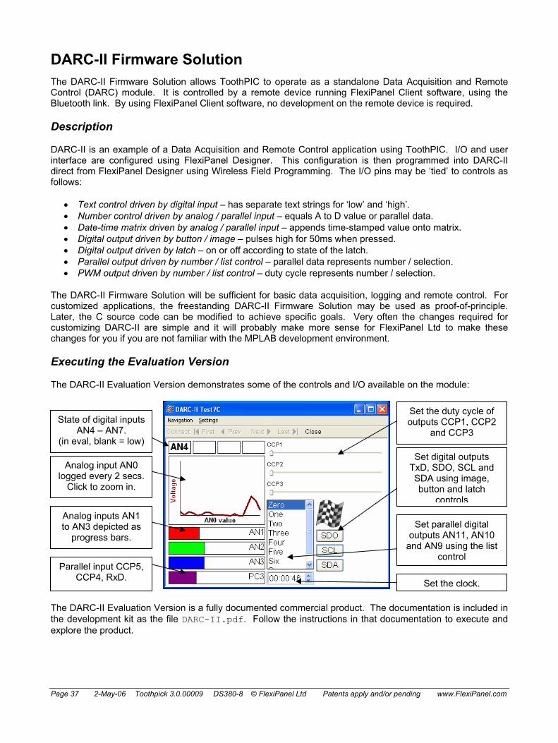
Page 37 2-May-06 Toothpick 3.0.00009 DS380-8 © FlexiPanel Ltd Patents apply and/or pending www.FlexiPanel.com
DARC-II Firmware Solution The DARC-II Firmware Solution allows ToothPIC to operate as a standalone Data Acquisition and Remote Control (DARC) module. It is controlled by a remote device running FlexiPanel Client software, using the Bluetooth link. By using FlexiPanel Client software, no development on the remote device is required.
Description
DARC-II is an example of a Data Acquisition and Remote Control application using ToothPIC. I/O and user interface are configured using FlexiPanel Designer. This configuration is then programmed into DARC-II direct from FlexiPanel Designer using Wireless Field Programming. The I/O pins may be ‘tied’ to controls as follows:
• Text control driven by digital input – has separate text strings for ‘low’ and ‘high’. • Number control driven by analog / parallel input – equals A to D value or parallel data. • Date-time matrix driven by analog / parallel input – appends time-stamped value onto matrix. • Digital output driven by button / image – pulses high for 50ms when pressed. • Digital output driven by latch – on or off according to state of the latch. • Parallel output driven by number / list control – parallel data represents number / selection. • PWM output driven by number / list control – duty cycle represents number / selection.
The DARC-II Firmware Solution will be sufficient for basic data acquisition, logging and remote control. For customized applications, the freestanding DARC-II Firmware Solution may be used as proof-of-principle. Later, the C source code can be modified to achieve specific goals. Very often the changes required for customizing DARC-II are simple and it will probably make more sense for FlexiPanel Ltd to make these changes for you if you are not familiar with the MPLAB development environment.
Executing the Evaluation Version
The DARC-II Evaluation Version demonstrates some of the controls and I/O available on the module:
The DARC-II Evaluation Version is a fully documented commercial product. The documentation is included in the development kit as the file DARC-II.pdf. Follow the instructions in that documentation to execute and explore the product.
Set the duty cycle of outputs CCP1, CCP2
and CCP3
Set digital outputs TxD, SDO, SCL and SDA using image, button and latch
controls
Set parallel digital outputs AN11, AN10
and AN9 using the list control
Set the clock.
State of digital inputs AN4 – AN7.
(in eval, blank = low)
Analog input AN0 logged every 2 secs.
Click to zoom in.
Analog inputs AN1 to AN3 depicted as
progress bars.
Parallel input CCP5, CCP4, RxD.

Page 38 2-May-06 Toothpick 3.0.00009 DS380-8 © FlexiPanel Ltd Patents apply and/or pending www.FlexiPanel.com
The documentation is of interest in itself because it gives an indication of important elements which should be included in commercial products using DARC-II. In particular, note:
• Patents apply and/or pending – all products incorporating ToothPIC are implicitly protected by FlexiPanel’s patents and patent applications.
• Field-Programming Instructions – demonstrating this advanced feature of the product which relieves you of the need to manage multiple product lines each with different firmware.
• Antenna position guidance. • Current requirements – since peak current requirement is relatively high. • FCC / CE / IC Modular Approval – device labeling requirements.
Customization in MPLAB
The standard DARC-II Firmware Solution can do the following:
• Configure the I/O. • Provide a user interface. • Link the user interface controls directly to the I/O.
If you wish to customize the DARC-II module further, you will need to use the MPLAB development environment. If you have not already done so, please study the Hello World applications.
Migrating to MPLAB
The following instructions allow you to migrate the Evaluation Application solution to the MPLAB development environment.
1. The application code for the DARC-II firmware solution is extensive and the entire project is in the development kit. In MPLAB, open the project DARC-II.mcw. This relevant files in the project are:
DARC-II.c – Main application code which you will be customizing. DARCIIConfig.c – A data structure containing the default I/O configuration. DARCIIDefaultRes.c – Default user interface code which just contains the text ‘DARC-II’. DARCIIDefaultRes.h – Default user interface macros. ToothPIC.h – General ToothPIC macros.
When you configure DARC-II wirelessly using FlexiPanel Designer, it overwrites the data in DARCIIConfig.c and DARCIIDefaultRes.c with the configuration you specify.
2. If the files were compiled as they are, the user interface would be the default user interface, which just contains the text ‘DARC-II’. To replace this with the DARCIITestRes.FxP user interface in the evaluation version example:
• Open DARCIITestRes.FxP in FlexiPanel Designer. • In the Target Device menu, select ToothPIC. • In the Target Device menu, select Create C Code. The C files DARCIITestRes.c and
DARCIITestRes.h are created. • Remove DARCIIDefaultRes.c and DARCIIDefaultRes.h from the project. • Add DARCIITestRes.c and DARCIITestRes.h to the project.

Page 39 2-May-06 Toothpick 3.0.00009 DS380-8 © FlexiPanel Ltd Patents apply and/or pending www.FlexiPanel.com
3. To customize the I/O configuration, you will need to modify the I/O configuration data structure initialized in DARCIIConfig.c and described in detail in DARCIIConfig.h. Rather than modify the DARCIIConfig.c file directly, it is better to overwrite the data during program initialization. This allows you to use the macros in DARCIITestRes.h so that if you add or delete controls, the control ID information is automatically updated. (The SetBytes function only writes to Flash memory if the values are different from the desired values, so this will not exhaust the Flash memory.) To customize the I/O configuration, open the file DARC-II.c and insert the following lines at the beginning of the main() function (or copy them from the file DARC-II Customized.c file in the development kit):
// main program #include "DARCIITestRes.h" rom unsigned char szMyName[] = "My Product Title"; void main( void ) { unsigned char cVal; PulseClearCountDown = 0; RefeshInputsNow = 0; // if no BlueMatik, flash red led rapidly while ((ToothPICSemaphores&TPSF_BMTEXISTS)==0) { LedRed = ~LedRed; msDelay(50); } // customize DARCcfg cVal = 0x55; // indicates config data has been initialized SetBytes( STR_ROM00, (ADD)&DARCcfg.Initialized, 0, &cVal, 1 ); // device name SetBytes( STR_ROM00, (ADD)DARCcfg.ServerName, szMyName, 0, MAXNAMELENGTHINCZ ); // four analog channels, AN0 to AN3 cVal = 0x04; SetBytes( STR_ROM00, (ADD)&DARCcfg.nAnalogChannel, 0, &cVal, 1 ); // configure I/O; note default values are zeroes so if a value is zero, / we don't bother altering it // DARCcfg.h explains the cVal values being used cVal = 0x01; // output SetBytes( STR_ROM00, (ADD)&DARCcfg.PinFuncAN9, 0, &cVal, 1 ); SetBytes( STR_ROM00, (ADD)&DARCcfg.PinFuncAN10, 0, &cVal, 1 ); SetBytes( STR_ROM00, (ADD)&DARCcfg.PinFuncAN11, 0, &cVal, 1 ); SetBytes( STR_ROM00, (ADD)&DARCcfg.PinFuncTxD, 0, &cVal, 1 ); SetBytes( STR_ROM00, (ADD)&DARCcfg.PinFuncSCL, 0, &cVal, 1 ); SetBytes( STR_ROM00, (ADD)&DARCcfg.PinFuncSDA, 0, &cVal, 1 ); SetBytes( STR_ROM00, (ADD)&DARCcfg.PinFuncSDO, 0, &cVal, 1 ); cVal = 0x02; // PWM output SetBytes( STR_ROM00, (ADD)&DARCcfg.PinFuncCCP1, 0, &cVal, 1 ); SetBytes( STR_ROM00, (ADD)&DARCcfg.PinFuncCCP2, 0, &cVal, 1 ); SetBytes( STR_ROM00, (ADD)&DARCcfg.PinFuncCCP3, 0, &cVal, 1 ); cVal = 0x03; // Parallel A and Parallal C are both 3-bits wide SetBytes( STR_ROM00, (ADD)&DARCcfg.ParallelA, 0, &cVal, 1 ); SetBytes( STR_ROM00, (ADD)&DARCcfg.ParallelC, 0, &cVal, 1 ); cVal = 0x02; // Timebase is 3.2us ( SetBytes( STR_ROM00, (ADD)&DARCcfg.ParallelA, 0, &cVal, 1 ); cVal = 0xFF; // PWM period is (0xFF + 1) = 256 Timebase units SetBytes( STR_ROM00, (ADD)&DARCcfg.PWMPeriod, 0, &cVal, 1 ); cVal = 0x05; // Refresh every two seconds SetBytes( STR_ROM00, (ADD)&DARCcfg.RefreshRate, 0, &cVal, 1 ); // link controls to I/O cVal = TFP_BILT_TxD; SetBytes( STR_ROM00, (ADD)&DARCcfg.ToFromPin[ID_TxD_1B], 0, &cVal, 1 ); cVal = TFP_BILT_SDO; SetBytes( STR_ROM00, (ADD)&DARCcfg.ToFromPin[ID_SDO_7], 0, &cVal, 1 ); cVal = TFP_BILT_SDA; SetBytes( STR_ROM00, (ADD)&DARCcfg.ToFromPin[ID_SDA_8], 0, &cVal, 1 ); cVal = TFP_BILT_SCL; SetBytes( STR_ROM00, (ADD)&DARCcfg.ToFromPin[ID_SCL_9], 0, &cVal, 1 ); cVal = TFP_NDTM_AN0; SetBytes( STR_ROM00, (ADD)&DARCcfg.ToFromPin[ID_AN0_18], 0, &cVal, 1 ); cVal = TFP_NDTM_AN1; SetBytes( STR_ROM00, (ADD)&DARCcfg.ToFromPin[ID_AN1_C], 0, &cVal, 1 ); cVal = TFP_NDTM_AN2; SetBytes( STR_ROM00, (ADD)&DARCcfg.ToFromPin[ID_AN2_D], 0, &cVal, 1 ); cVal = TFP_NDTM_AN3; SetBytes( STR_ROM00, (ADD)&DARCcfg.ToFromPin[ID_AN3_E], 0, &cVal, 1 ); cVal = TFP_NDTM_ParallelC;

Page 40 2-May-06 Toothpick 3.0.00009 DS380-8 © FlexiPanel Ltd Patents apply and/or pending www.FlexiPanel.com
SetBytes( STR_ROM00, (ADD)&DARCcfg.ToFromPin[ID_PC3_F], 0, &cVal, 1 ); cVal = TFP_L_ParallelA; SetBytes( STR_ROM00, (ADD)&DARCcfg.ToFromPin[ID_PC3_F], 0, &cVal, 1 ); cVal = ID_CCP1_11; SetBytes( STR_ROM00, (ADD)&DARCcfg.ToFromPin[TFP_NDTM_CCP1], 0, &cVal, 1 ); cVal = ID_CCP2_12; SetBytes( STR_ROM00, (ADD)&DARCcfg.ToFromPin[TFP_NDTM_CCP2], 0, &cVal, 1 ); cVal = ID_CCP3_13; SetBytes( STR_ROM00, (ADD)&DARCcfg.ToFromPin[TFP_NDTM_CCP3], 0, &cVal, 1 ); cVal = TFP_BILT_AN4; SetBytes( STR_ROM00, (ADD)&DARCcfg.ToFromPin[ID_AN4_14], 0, &cVal, 1 ); cVal = TFP_BILT_AN5; SetBytes( STR_ROM00, (ADD)&DARCcfg.ToFromPin[ID_AN5_15], 0, &cVal, 1 ); cVal = TFP_BILT_AN6; SetBytes( STR_ROM00, (ADD)&DARCcfg.ToFromPin[ID_AN6_16], 0, &cVal, 1 ); cVal = TFP_BILT_AN7; SetBytes( STR_ROM00, (ADD)&DARCcfg.ToFromPin[ID_AN7_17], 0, &cVal, 1 ); // if darc data has been programmed, set name and pin code // new name only appears in device discovery after ToothPIC reset if (DARCcfg.Initialized==0x55) { SetBytes( STR_ROM00, (ADD)pLocalName, DARCcfg.ServerName, 0,MAXNAMELENGTHINCZ); SetBytes( STR_ROM00, (ADD)pszPIN, DARCcfg.PINCode, 0, MAXPINLENGTHINCZ ); }
4. Compile the code and program it into the ToothPIC.
The version of DARC-II that you have created should perform in exactly the same way as the example in the Evaluation Version, except that now you can modify the rest of the code as you wish. The key features of the source code are described below.
Initialization
After variables are initialized, the I/O and Bluetooth security are set as specified by the DARCcfg data structure. The FlexiPanel user interface server is started. Finally, the function RefreshInputs() is called to correctly set the state of any controls which are driven by the state of the I/O pins.
Main Program Loop
In the main program loop, the software determines whether the semaphore PulseClearCountDown has been raised to request that it clears, after a 50ms pause, any I/O pins which are configured for pulse output. If the semaphore is raised at any time while it is counting up to 50ms, is starts its 50ms delay count again. This ensures that if two pins are pulsed in rapid succession, both pulses will be at least 50ms long. If the semaphore was not raised at all, DARC-II simply waits 50ms. Either way, the delay is probably 50ms, possibly a bit more.
If the refresh rate is 100ms, 200ms or 500ms, DARC-II waits the specified time (less the 50ms already waited) and calls RefreshInputs()to update the inputs. If the refresh rate is longer than this, the LowInterrupt callback will raise the semaphore RefeshInputsNow if it is time to refresh the inputs. In this case, DARC-II inspects the semaphore to decide whether to call RefreshInputs().
High Interrupt
No high priority interrupts are expected nor provided for.
Low Interrupt
One type of low priority interrupts is provided for: when the clock ticks.
Every second, a SWI_Tick software interrupt will be received. DARC-II inverts the green LED to show that is it working correctly. Note that this is not infallible indication since, if the main program loop hangs, SWI_Tick software interrupts will probably still be generated correctly.
Next DARC-II decides whether it is time to raise the RefeshInputsNow semaphore and does so if required.

Page 41 2-May-06 Toothpick 3.0.00009 DS380-8 © FlexiPanel Ltd Patents apply and/or pending www.FlexiPanel.com
Finally, the SWI_Tick software interrupt is cleared.
ErrorStatus
If the client disconnects ungracefully, for example by going out of range, a general error (code 0x0F) may be generated because BlueMatik will not know what to do with the data DARC-II is giving it. During development, it is best to set a breakpoint so we can confirm what caused the error. For product release, it is obviously better to reset immediately.
BMTEvent
Errors are handled in the same way as for ErrorStatus, although no errors are expected.
FlexiPanel Server Events
If a FlexiPanel Client connects, a FxPE_Connected event is generated and DARC-II lights the red LED.
If a FlexiPanel Client disconnects, a FxPE_Disco event is generated and DARC-II turns off the red LED.
If a FlexiPanel Client modifies a control, a FxPE_ClntUpdate event is generated and DARC-II calls the function ControlChanged().
ControlChanged()
The ControlChanged() function identifies which control has changed and decides whether an output needs to be changed. Since DARC-II Evaluation Version will not know in advance what I/O setup exists, it must derive the information from the DARCcfg data structure. Equally, since it will not know in advance what controls exist, it cannot use any macros generated by the FlexiPanel Designer header file. It needs to use the pDevD, pDlgD and pCtlD data structures defined in ToothPIC.h to discover what controls exist.
RefreshInputs()
The RefreshInputs() function polls the state of the inputs and decides whether any control values need to be changed. As with ControlChanged(), the DARC-II Evaluation Version will not know in advance what I/O setup or user interface controls exist, so it must derive the information from the DARCcfg, pDevD, pDlgD and pCtlD data structures.
The RefreshInputs() function uses the FxPC_MultiUpdate message to send the updated controls to the FlexiPanel client to reduce communication time.
Auxiliary Functions
Auxiliary functions are provided for:
• Setting output pins according to the state of controls. • Retrieving the state of input pins.

Page 42 2-May-06 Toothpick 3.0.00009 DS380-8 © FlexiPanel Ltd Patents apply and/or pending www.FlexiPanel.com
HappyTerminal Firmware Solution Description
HappyTerminal is an example of a commercial application using ToothPIC. It is a terminal emulator for monitoring and injecting TTL-level serial data in digital electronic circuits and prototypes. It uses the FlexiPanel User Interface Server so that any Bluetooth-equipped Windows PC or Pocket PC can act as the user interface. HappyTerminal features in the September 2005 edition of Circuit Cellar.
Executing the Finished Application
The HappyTerminal firmware solution is a fully documented commercial product. The documentation is included in the development kit as the file HappyTerminal.pdf. Follow the instructions in the documentation to execute and explore the product. Note how the documentation includes:
• 1-page summary with ordering information – Allows the front page to be used as an information leaflet. • Pin descriptions – Summarizing the function of each pin. • Configuration guide – Including very simple schematic diagrams, as many users may be beginners. • Usage guide – Indicating how to operate HappyTerminal. • Settings guide – Indicating how to change from the default settings. • Mechanical data – To assist in PCB layout. • Technical specifications. • FCC / CE / IC Modular Approval – device labeling requirements. • Patents apply and/or pending – All products incorporating ToothPIC are implicitly protected by
FlexiPanel’s patents and patent applications.
User Interface Development in FlexiPanel Designer
The User Interface is defined in the file HappyTerminalRes.FxP. The main screen is actually composed of 20 individual text controls for the main blue portion of the screen and 20 individual text controls for the debug portion of the screen. Settings data is stored in EE memory so that it is retained when power is removed.
In the Pocket PC layout, the Debug controls overlay the main text controls. In the Windows layout, the Debug controls are placed to the right of the main text controls. This is because Windows is less reliable in placing child windows correctly. No attempt has been made to make the user interface suitable for Smartphone and Java phones because the user interface is too complex.
A separate settings dialog is used to adjust HappyTerminal configuration.
Application Development in MPLAB
If you wish to customize the HappyTerminal firmware, you will need to use the MPLAB development environment. If you have not already done so, please first read the section Guide To MPLAB C18 Development and study the Hello World firmware solutions.
The application code for the HappyTerminal firmware solution is extensive and the entire project is in the development kit. The most important files to note are the application source code file HappyTerminal.c and the Designer-generated macros header file HappyTerminalRes.h. The key features of the source code are discussed below.
Static variables and Declarations
Prior to the main() function in HappyTerminal.c:
• Static variables are declared, including a receive buffer to store bytes as they are received but before they have been processed.

Page 43 2-May-06 Toothpick 3.0.00009 DS380-8 © FlexiPanel Ltd Patents apply and/or pending www.FlexiPanel.com
• The I/O pins and semaphore flags are #defined.
Initialization
When the application starts, the FlexiPanel server is initialized. Then the current settings are read from the settings controls and the UART is initialized.
Main Program Loop
In the main program loop, the software flashes the green LED.
If an error is detected, the Red LED is allowed to remain lit for half a second; then, the UART is reset and the LED is extinguished.
High Interrupt
If a character is received, a high interrupt is generated. HappyTerminal stores the data in the receive buffer and sets the SWI_SWI1 software interrupt flag indicating that there is received data to be processed.
Low Interrupt
Two types of low priority interrupts are provided for: when the clock ticks and if the SWI_SWI1 software interrupt flag is raised.
Every second, a SWI_Tick software interrupt will be received. HappyTerminal simply clears the flag and returns.
The SWI_SWI1 software interrupt will be raised whenever there is data in the receive buffer to be processed. HappyTerminal transfers the data to the main screen in ASCII mode or Debug mode as appropriate.
ErrorStatus
No errors are expected. However, it is always possible that ToothPIC will enter an unanticipated state and generate an error. During development, it is best to set a breakpoint so that we can inspect what caused the error. For product release, it is obviously better to enter a failsafe state and/or reset.
BMTEvent
Errors are handled in the same way as for ErrorStatus.
FlexiPanel Server Events
If a FlexiPanel Client disconnects, a FxPE_Disco event is generated and HappyTerminal returns to the main screen if it was displaying the Settings screen.
If a FlexiPanel Client modifies a control, a FxPE_ClntUpdate event is generated and HappyTerminal deals with the information as would be expected. In particular, note:
Settings OK button. When pressed, the UART is reconfigured. If receive mode has been switched between Debug and ASCII, a new line is started.
Transmit edit OK button. When pressed, the data is read from the edit box, interpreted as ASCII or hexadecimal, and transmitted. The edit text is then cleared. If two-byte hexadecimal data was expected but the data cannot be interpreted as such, transmission will be aborted and the word Error will be written to the Transmit Edit text control.

Page 44 2-May-06 Toothpick 3.0.00009 DS380-8 © FlexiPanel Ltd Patents apply and/or pending www.FlexiPanel.com
If the FlexiPanel Server switches dialogs, a FxPE_NewDialog event is generated. This is used to show or hide the green Debug mode text controls, since control properties can only be modified on the client, not the server.
Auxiliary Functions
Auxiliary functions are provided for:
• Configuring the UART based on the values of the controls in the Settings dialog. • Hiding or showing the green Debug mode text controls. • Starting a new line in the main screen. • Transmitting a byte and echoing it if necessary.

Page 45 2-May-06 Toothpick 3.0.00009 DS380-8 © FlexiPanel Ltd Patents apply and/or pending www.FlexiPanel.com
OpenTooth Firmware Solution Description
OpenTooth is an example of a commercial application using ToothPIC. OpenTooth detects and recognizes Bluetooth devices within a 10m range, allowing OEMs to add Bluetooth capability to access control products. Typical applications include:
• Manual lock release – pulses relay when trusted device present and button pressed. • Automatic lock release – pulses relay while trusted device present. • Alarm deactivation – relay energizes while trusted device present. • Wiegand “card reader" – if button pressed, sends Wiegand codes of all devices present. • Personnel location tracker – sends Wiegand codes of all devices present at regular intervals.
Executing the Finished Application
The OpenTooth product is a fully documented commercial product. The documentation is included in the development kit as the file OpenTooth.pdf. Follow the instructions in that documentation to execute and explore the product.
The documentation is of interest in itself because it gives an indication of important elements which should be included in commercial products using OpenTooth. In particular, note:
• Patents apply and/or pending – all products incorporating ToothPIC are implicitly protected by FlexiPanel’s patents and patent applications.
• Field-Programming Instructions – demonstrating this advanced feature of the products which relieves you of the need to manage multiple product lines each with different firmware.
• Frequently Asked Questions – relating to safety, privacy and security. Always better to answer these questions before your customers ask them.
• Antenna position guidance. • Current requirements – since peak current requirement is relatively high. • FCC / CE / IC Modular Approval – device labeling requirements.
User Interface Development in FlexiPanel Designer
The User Interface is defined in the file OpenToothRes.FxP. The user interface design is quite big but not unusual. The ‘Access Log’ table and ‘Manual’ files button is used to provide an example of how to implement them. In practice, either would probably benefit from more external memory.
Application Development in MPLAB
If you wish to customize the OpenTooth module, you will need to use the MPLAB development environment. If you have not already done so, please first read the section Guide To MPLAB C18 Development.
The application code for the OpenTooth firmware solution is extensive and the entire project is in the development kit. The most important files to note are the application source code file OpenTooth.c and the Designer-generated macros header file OpenToothRes.h. The key features of the source code are discussed below.
Static variables and Declarations
Prior to the main() function in OpenTooth.c:
• Static variables are declared.

Page 46 2-May-06 Toothpick 3.0.00009 DS380-8 © FlexiPanel Ltd Patents apply and/or pending www.FlexiPanel.com
• The I/O pins, semaphore flags, relay trigger modes, Weigand data modes and access log modes are #defined.
• Two structures are defined for Bluetooth devices. UserEntry2 is used to store the results of device enquiry, contains the Bluetooth address and the device name. UserEntry10 is used to store registered users, also stores expiry data and timed access information.
• Two UserEntry2 arrays of devices are declared for device enquiry. pInquiryTable stores the devices while device inquiry is in progress. When device enquiry is complete, pInquiryTable is copied to pVicinityTable, which is a record of the all the devices found in the last complete inquiry.
• One UserEntry10 array is declared called pUserList which stores the registered users. This is held in ROM memory from 0x01C000.
Initialization
When the application starts, the I/O is initialized and Bluetooth security is set to authenticated and encrypted. The authentication PIN is set to the pin used to access the FlexiPanel user interface.
Main Program Loop
In the main program loop, the software detects whether the pushbutton has been pressed. If it has, it identifies whether this is a short press, a series of short presses or a long press.
The action taken on a short press depends on how OpenTooth is configured. If automatic triggering mode is configured, it will start the ‘sleep’ mode because a user is staying in the vicinity. If manual triggering mode is configured, the relay is triggered if a trusted device is in the vicinity. If in Weigand card reader mode, it will transmit Weigand data.
If there have been five short presses, OpenTooth enters ‘new user’ mode where it lets a new user pair with it. To do this it sets the PIN to the ‘new user’ PIN, cancels any current enquiry cycle and goes into slave mode. While in ‘new user’ mode, it will wait 5 minutes for a new user to connect. If they do not do so, OpenTooth resets.
If there was a long press, OpenTooth enters ‘setup’ mode where it lets a FlexiPanel client connect to it. To do this it cancels any current enquiry cycle and starts the FlexiPanel server. While in ‘setup’’ mode, it will wait 5 minutes for a FlexiPanel client to connect. If they do not do so, OpenTooth resets.
If none of the above pushbutton events occur, OpenTooth will start a device enquiry to scan for devices. This will result in a BMTE_Found for each device found and a BMTE_OK event when the scan is complete.
If a once-per-minute semaphore is raised to start an expired users check, OpenTooth checks all registered users to decide whether any have expired. If they have, it deletes them from the table of registered users.
High Interrupt
No high priority interrupts are expected nor provided for.
Low Interrupt
Two types of low priority interrupts are provided for: when the clock ticks and if data is received from a remote device.
Every second, a SWI_Tick software interrupt will be received. OpenTooth first checks that the ‘In DST no’ flag is up to date. Then, if the seconds value is zero, a semaphore will be raised so that, in the main program loop, an expired users check will be executed.
It is possible that a malevolent user might try to connect to OpenTooth in ‘new user’ mode and then try to send data to it. This will generate a SWI_BMTData software interrupt and OpenTooth immediately resets.

Page 47 2-May-06 Toothpick 3.0.00009 DS380-8 © FlexiPanel Ltd Patents apply and/or pending www.FlexiPanel.com
ErrorStatus
Controls may be updated while the FlexiPanel server is not operating. This is not a problem in itself but it does generate ERR_NOFLEXIPANELSERVICE warning which needs to be ignored.
No other errors are expected. However, it is always possible that ToothPIC will enter an unanticipated state and generate an error. During development, it is best to set a breakpoint so that we can inspect what caused the error. For product release, it is obviously better to enter a failsafe state and/or reset.
BMTEvent
Errors are handled in the same way as for ErrorStatus.
If a device is found during a device inquiry, a BMTE_Found event is generated and OpenTooth adds the device to the ‘new devices’ table pInquiryTable. If it is a trusted device the ‘trusted device in the vicinity’ flag is raised and the relay and Weigand outputs are triggered as appropriate.
If a device inquiry cycle completes, a BMTE_OK event is generated and OpenTooth copies the table pInquiryTable to the ‘devices in the vicinity’ table, pVicinityTable. If no trusted devices are in the vicinity, the ‘trusted device in the vicinity’ flag is lowered and the relay output is cleared if appropriate.
It is possible that a malevolent user might try to connect to OpenTooth in ‘new user’ mode and then try to send data to it. This will generate a BMTE_Connect software interrupt and OpenTooth immediately resets.
If a user successfully pairs in ‘new user’ mode, a BMTE_Paired event is generated. OpenTooth adds the new user to the list of registered users, pUserList. The pairing does not actually tell us the device’s name, so we might need to use the name ‘anonymous’; however, if it was around in the previous device inquiry cycle, its name will be in pVicinityTable and the name found there will be used.
FlexiPanel Server Events
If a FlexiPanel Client connects, a FxPE_Connected event is generated and OpenTooth lights the LED.
If a FlexiPanel Client disconnects, a FxPE_Disco event is generated and OpenTooth resets to resume normal operation.
If a FlexiPanel Client modifies a control, a FxPE_ClntUpdate event is generated and OpenTooth deals with the information as would be expected.
Auxiliary Functions
Auxiliary functions are provided for:
• Converting from binary to ASCII hexadecimal characters. • Updating the Modify Users dialog. • Updating the Registered Users dialog. • Checking whether a trusted user is allowed access at this time of day and day of week. • Pulsing the relay. • Logging data to the access log. • Adding or modifying a user in the list of registered users. • Transmitting data in Weigand format. Note that WEIG_5V and WEIG_0V are #defined assuming drive
transistors will the outputs. These will have to be modified if no drive transistors are used.

Page 48 2-May-06 Toothpick 3.0.00009 DS380-8 © FlexiPanel Ltd Patents apply and/or pending www.FlexiPanel.com
ToothPIC Slave Firmware Solution Slave mode is a serial interface providing access to ToothPIC Services and I/O. This allows developers to use an external microcontroller to customize their application rather than having to learn the MPLAB development environment and PIC microcontrollers in depth.
BlueMatik uses the term ‘slave mode’ in a different sense, where the Bluetooth radio is in a discoverable and connectable state. The firmware solution always referred to by its full name, ‘ToothPIC Slave’.
Description
ToothPIC Slave is intended for rapid development of ToothPIC applications without the need to be familiar with the MPLAB development environment. At a later date, the complete application can be migrated to the ToothPIC and the host controller is simply omitted from the bill of materials – not even the PCB layout need to be changed.
ToothPIC Slave understands commands for:
• System reset. • General configuration. • I/O configuration. • Setting an output value. • Reading an input value. • Managing Bluetooth connections. • Sending and receiving Bluetooth data. • FlexiPanel User Interface Server management. • Sending and receiving user interface control information. • Reading and writing to memory locations. • Real time clock control.
Commands generate responses from ToothPIC Slave. In addition, unsolicited responses may occur, for example if a user modifies a control. For this reason, a response message queue is implemented. The host can manage the flow of messages by one of: (i) having a sufficiently large buffer to store all incoming messages, (ii) using hardware flow control to request messages one at a time, or (iii) using a ‘ready for next response message’ command.
Initializing ToothPIC Slave
The ToothPIC Slave Firmware Solution must be ‘Field Programmed’ into the ToothPIC. This takes a few seconds and requires either a Windows PC or a Pocket PC with Bluetooth. The procedure is as follows. If required use the default PIN code 0000.
1. Download the ToothPIC Development Kit from www.flexipanel.com and locate the ToothPIC Slave Service Pack ToothPICSlaveWin.exe (Windows) or ToothPICSlavePPC.exe (Pocket PC).
2. Power-up the ToothPIC Slave with the on-board pushbutton held down. The on-board LEDs will flash simultaneously.
3. Start running the ToothPIC Slave Service Pack and connect from the computer to the ToothPIC using Bluetooth.

Page 49 2-May-06 Toothpick 3.0.00009 DS380-8 © FlexiPanel Ltd Patents apply and/or pending www.FlexiPanel.com
4. Enter the COM port used to connect to the ToothPIC in the box provided.
5. Press the Update button. Programming takes about 30 seconds. When the progress bar is full, field programming is complete.
If you have not yet connected the host controller, the red LED may illuminate indicating a serial receive error. The red LED error indicator is self-resetting and will extinguish after half a second when you have correctly connected the stamp. You may also get this indication if the host’s baud rate is wrong.
A Quick Tour
To evaluate ToothPIC slave, you are going to be the host. ToothPIC is intended to respond to binary commands, but it can also accept the same commands if typed in ASCII hexadecimal. To send typed ASCII hexadecimal commands to ToothPIC Slave, you will need to connect it to a terminal emulator. The instructions which follow assume you will use the HyperTerminal program which comes bundled free with the Windows operating system. You will need a Windows PC with a serial port (or USB serial port adapter).
6. The serial outputs of ToothPIC are TTL level and need to be converted to RS232 level. For this, we recommend a MAX233 level converter because all voltage doubling components are integrated into the circuit. Follow the this reference schematic or provide some other circuit:
ToothPIC
Vdd
Vss
CTS
RTS
RxD
TxD
Vss
Vss
MAX233T1in
R1out
Vdd
Slave
Vdd
1uF
T1in T1out
T2outT2in
R2in
R1in
R2out19
4
5
18
20
3
20
1
DB9 (Female)connector
12
17
PIN numbers for MAX233 DIP package. SO package pin numbers differ.
11
15
16 10 6 9
7
1
2
3
4
5
6
7
8
9
Pin 5
Pin 2
Pin 3
Pin 8
Pin 7
Circuit is for a DCE configured device for direct connection to DTE device such as a Windows PC.
If you do not have a MAX233, you can use any circuit you wish so long as RxD and TxD are level translated fully duplex.
When initialized, ToothPIC has no CTS and RTS flow control and you should connect just (i) R2out to T2in.If you later enable flow control, connect (ii) R2out to CTS and (iii) T2in to RTS as shown instead.
See text below regarding i, ii and iii.
ii
iii i
7. The ToothPIC Slave defaults are deliberately chosen to permit connection to HyperTerminal ‘straight out of the box’. Once physically connected, start HyperTerminal and select the following settings:
• Connect using COM port as appropriate. • 9600 baud (bits per second). • 8 data bits, no parity, 1 stop bit • No flow control. (You enable it later after you have enabled Flow Control on the ToothPIC.) • (In Properties > ASCII Setup) Send line ends with line feeds. • Echo characters locally.
8. Power up the ToothPIC. After a couple of seconds the LEDs will flash and HyperTerminal should display the following initialization message:
10536E61766620332E302E3030303032
9. As a first test, we will set an I/O pin as an output and set it high. Connect an LED with a current limiting resistor to pin AN11 so that it would light if the pin were high.
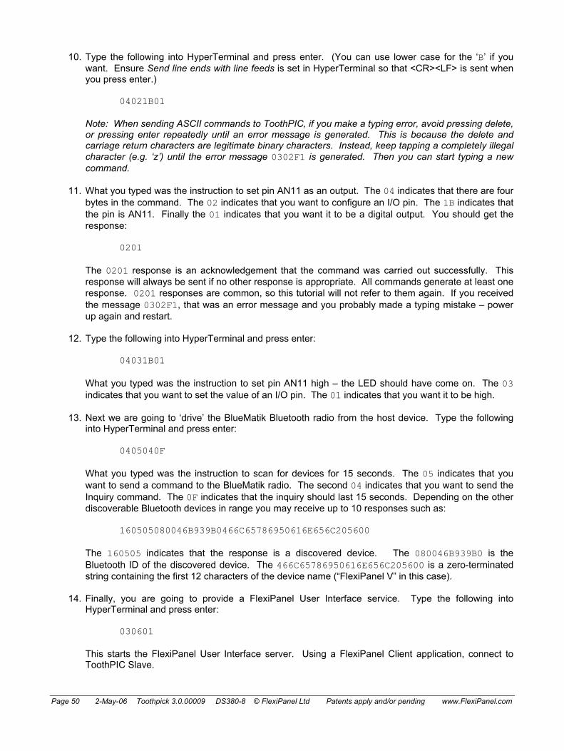
Page 50 2-May-06 Toothpick 3.0.00009 DS380-8 © FlexiPanel Ltd Patents apply and/or pending www.FlexiPanel.com
10. Type the following into HyperTerminal and press enter. (You can use lower case for the ‘B’ if you want. Ensure Send line ends with line feeds is set in HyperTerminal so that <CR><LF> is sent when you press enter.)
04021B01
Note: When sending ASCII commands to ToothPIC, if you make a typing error, avoid pressing delete, or pressing enter repeatedly until an error message is generated. This is because the delete and carriage return characters are legitimate binary characters. Instead, keep tapping a completely illegal character (e.g. ‘z’) until the error message 0302F1 is generated. Then you can start typing a new command.
11. What you typed was the instruction to set pin AN11 as an output. The 04 indicates that there are four bytes in the command. The 02 indicates that you want to configure an I/O pin. The 1B indicates that the pin is AN11. Finally the 01 indicates that you want it to be a digital output. You should get the response:
0201
The 0201 response is an acknowledgement that the command was carried out successfully. This response will always be sent if no other response is appropriate. All commands generate at least one response. 0201 responses are common, so this tutorial will not refer to them again. If you received the message 0302F1, that was an error message and you probably made a typing mistake – power up again and restart.
12. Type the following into HyperTerminal and press enter:
04031B01
What you typed was the instruction to set pin AN11 high – the LED should have come on. The 03 indicates that you want to set the value of an I/O pin. The 01 indicates that you want it to be high.
13. Next we are going to ‘drive’ the BlueMatik Bluetooth radio from the host device. Type the following into HyperTerminal and press enter:
0405040F
What you typed was the instruction to scan for devices for 15 seconds. The 05 indicates that you want to send a command to the BlueMatik radio. The second 04 indicates that you want to send the Inquiry command. The 0F indicates that the inquiry should last 15 seconds. Depending on the other discoverable Bluetooth devices in range you may receive up to 10 responses such as:
160505080046B939B0466C65786950616E656C205600
The 160505 indicates that the response is a discovered device. The 080046B939B0 is the Bluetooth ID of the discovered device. The 466C65786950616E656C205600 is a zero-terminated string containing the first 12 characters of the device name (“FlexiPanel V” in this case).
14. Finally, you are going to provide a FlexiPanel User Interface service. Type the following into HyperTerminal and press enter:
030601
This starts the FlexiPanel User Interface server. Using a FlexiPanel Client application, connect to ToothPIC Slave.

Page 51 2-May-06 Toothpick 3.0.00009 DS380-8 © FlexiPanel Ltd Patents apply and/or pending www.FlexiPanel.com
15. When you successfully connect, you will see a very simple User Interface as shown in the graphic on the right. It contains only the words ‘ToothPIC Slave’. In HyperTerminal, you should see the following responses:
090503080046B939B0 (Last 12 chars will differ.)
030601
The 09050308 message is from BlueMatik and indicates that a Bluetooth device has connected. The last 12 characters are the Bluetooth ID of the device. The 030601 message is from the FlexiPanel server and indicates that the device is a FlexiPanel Client.
16. This user interface is a bit dull, so we will now program a more interesting User Interface into ToothPIC Slave. Run the FlexiPanel Designer application and open the file SlaveTestRes.FxP from the development kit. This is exactly the same as the DARCIITestRes.FxP example used in the DARC-II firmware solution, except that the target has been set to ToothPIC Slave. If you want to know more about what all the settings mean and how the file was created, follow the tutorial in the DARC-II module product documentation.
17. Power-up the ToothPIC Slave with the pushbutton pressed down. The LEDs will flash rapidly, indicating that it is allowing itself to be configured. Connect to the module from your Windows PC and make a note of the COM port that Bluetooth uses. In FlexiPanel Designer menu, select View > ToothPIC Slave Properties and, in the properties list on the right, find the property ‘Programming COM Port’ and set the value to the COM port that Bluetooth is using. In FlexiPanel Designer menu, select Target Device > Program ToothPIC Slave from the menu. The user interface will be programmed into the ToothPIC Slave.
18. When programming is complete, ToothPIC Slave will automatically reset and you will see the initialization message again in the HyperTerminal window. Set the application name and restart the FlexiPanel Service again by typing into HyperTerminal the following:
030601
and then connect to ToothPIC again from a FlexiPanel client. The User Interface will be the same as the DARC-II module. If you modify any controls, you will get corresponding responses in the HyperTerminal window. Type the following into HyperTerminal:
060D00050000 060D0005FF03 060D0005FF01
Observe how you just added rows to the matrix control.
That completes the quick tour. For more information on commands, etc, refer to the section Guide to

Page 52 2-May-06 Toothpick 3.0.00009 DS380-8 © FlexiPanel Ltd Patents apply and/or pending www.FlexiPanel.com
ToothPIC Slave Development.
Migration to MPLAB
The ToothPIC Slave Firmware Solution can do most things that ToothPIC is capable of. You may, however, wish to customize it either to migrate your host controller application inside ToothPIC or to access specialized PIC functions.
To make customization possible, we have made the C source code freely available for you to customize. To do this you will need to know how to program microcontrollers in C and also be familiar with Microchip Technology’s MPLAB development environment.
Since many customization requirements are relatively simple, we offer a paid-for customization service to commercial developers who are not familiar with programming in the MPLAB development environment. Please contact us for details.
The following instructions allow you to migrate the Evaluation Application solution to the MPLAB development environment. If you have not already done so, please study the Hello World applications to understand how interaction with ToothPIC Services works. The relevant code is in the file Slave.c in the Development Kit.
User Interface
If you customize the application, it is easiest to program the user interface by setting ToothPIC MPLAB as the Designer target and including the files generated by FlexiPanel Designer in the project in place of SlaveDefaultRes.c and SlaveDefaultRes.h. The header file will contain useful macros which get updated if control IDs change.
Because the ToothPIC Slave Firmware Solution does not know the User Interface information in advance, the required memory needed to be reserved for it. Therefore you may remove the lines:
#pragma romdata Section_010000 = 0x0101D7 rom unsigned char p010000[0x3E29]; // first 0x01D7 Bytes in SlaveDefaultRes.h #pragma romdata Section_014000 = 0x014000 rom unsigned char p014000[0x4000]; #pragma romdata Section_018000 = 0x018000 rom unsigned char p018000[0x4000]; #pragma romdata Section_01C000 = 0x01C000 rom unsigned char p01C000[0x3000]; #pragma romdata
and also the lines:
#pragma udata TP_UIRAM000 // located at 0x100 - 0x1FF unsigned char pFxPRAM000B[0xFF]; #pragma udata TP_UIRAM100 // located at 0x200 - 0x1FF unsigned char pFxPRAM100[0x100]; #pragma udata TP_UIRAM200 // located at 0x300 - 0x1FF unsigned char pFxPRAM200[0x100]; #pragma udata TP_UIRAM300 // located at 0x400 - 0x8FF unsigned char pFxPRAM300[0x100]; #pragma udata TP_UIRAM400 // located at 0x500 - 0x8FF unsigned char pFxPRAM400[0x100]; #pragma udata TP_UIRAM500 // located at 0x600 - 0x8FF unsigned char pFxPRAM500[0x100]; #pragma udata TP_UIRAM600 // located at 0x700 - 0x8FF unsigned char pFxPRAM600[0x100]; #pragma udata TP_UIRAM700 // located at 0x800 - 0x8FF unsigned char pFxPRAM700[0x100]; #pragma udata
However, you must reserve space for your message queue just below 0x900, otherwise the linker might try to use the memory. The following example allocates enough memory for a message queue of 11 messages of 22 bytes:
#pragma udata MESSAGESTACK=0x80E // located at 0x80E - 0x8FF unsigned char pMessage[0xF2]; #pragma udata

Page 53 2-May-06 Toothpick 3.0.00009 DS380-8 © FlexiPanel Ltd Patents apply and/or pending www.FlexiPanel.com
Initialization
ToothPIC Slave reads permanently stored settings from EE memory. Then it initializes the following:
• Message queue. • Serial port for communication with the host. • Flow control. • External memory, if required. • Bluetooth security.
After variables are initialized, the I/O and Bluetooth security are set as specified by the DARCcfg data structure. The FlexiPanel user interface server is started. Finally, the LEDs are flashed and the initialization string transmitted to show that initialization is complete.
Main Program Loop
There is nothing in the main program loop. All the required processing takes place in interrupts. If you want to port your host controller into the ToothPIC, you can do whatever you like here and/or in the callback routines.
High Interrupt
The high priority interrupt is used to add incoming bytes to the receive buffer. This is placed in high priority interrupt because no other task may prevent it from being read before the next byte arrives. If the entire command has been received, the software interrupt SWI_SWI1 is raised so that the command is processed in the low priority interrupt.
Low Interrupt
Six types of low priority interrupts are provided for:
• Restarting transmission if the CTS pin goes low. • Loading the next byte into the UART once the current byte has started being sent. • Clearing the SWI_Tick interrupt. • Processing commands as they are received. • Pulling a message off the message queue and transmitting it. • Reading raw data received from a non-FlexiPanel remote device and transmitting it to the host.
Note the use of two software interrupts. This allows one interrupt to trigger another safely.
ErrorStatus
No errors are expected. If an error occurs, the auxiliary function InternalError() performs whatever task is supposed to be performed in the event of an error.
BMTEvent
Errors are handled in the same way as for ErrorStatus. Most other events are converted to responses to send to the host and are added to the message queue.
FlexiPanel Server Events
FlexiPanel Server Events converted to responses to send to the host and are added to the message queue.

Page 54 2-May-06 Toothpick 3.0.00009 DS380-8 © FlexiPanel Ltd Patents apply and/or pending www.FlexiPanel.com
Message Queue Management
AppendToMessage() concatenates a string onto a message being constructed at the tail of the message queue. AddMessageToQueue() then advances the queue and raises software interrupt SWI_SWI2 to signal that a message requires transmission.
SendNextMessage() pulls a message off the queue, loads it into the transmit buffer and starts transmitting it.
Command Processing Functions
13 command processing functions are provided:
• ConfigSlvCmd() for processing Configure Slave commands. • ConfigIOCmd() for processing Configure I/O commands. • SetIOCmd() for processing Set I/O commands. • GetIOCmd() for processing Get I/O commands. • BMTCmd() for processing BlueMatik commands. • FxPCmd() for processing FlexiPanel Server commands. • GetFxPInfoCmd() for processing User Interface Info commands. • GetCtlCmd() for processing Get Control Data commands. • SetCtlPropsCmd() for processing Set Control Props commands. • SetCtlCmd() for processing Set Control Data commands. • SetRowCmd() for processing Set Row, Append Row and Log Row commands. • GetMemCmd() for processing Get Memory commands. • GetMemCmd() for processing Set Memory commands.
While these functions are extensive, their functions are self-evident.
Auxiliary Functions
Auxiliary functions are provided for:
• Signaling an error. • Converting from ASCII hexadecimal to binary. • Sending an 0201 (“OK”) response. • Sending DateTime response. • Transmitting IO values responses. • Converting from Control ID to a control array index value.

Page 55 2-May-06 Toothpick 3.0.00009 DS380-8 © FlexiPanel Ltd Patents apply and/or pending www.FlexiPanel.com
Guide to ToothPIC Slave Development HyperTerminal Setup
The easiest way to experiment with ToothPIC Slave is to connect it to a terminal emulator such as HyperTerminal, which is bundled with the Windows operating systems. Notes on how to do this are given in the section ToothPIC Slave Firmware Solution.
Note: When sending ASCII commands to ToothPIC, if you make a typing error, avoid pressing delete, or pressing enter repeatedly until an error message is generated. This is because the delete and carriage return characters are legitimate binary characters. Instead, keep tapping a completely illegal character (e.g. ‘z’) until the error message 0302F1 is generated. Then you can start typing a new command.
BASIC Stamp Host Setup
ToothPIC can be connected directly to BASIC Stamp using any data pins. To send data at 9600 baud to ToothPIC, use the following BASIC command (substitute RxDpin, RTSpin with the actual pins used):
SEROUT RxDpin\RTSpin, 240, [Command]
To receive data at 9600 baud from ToothPIC, use the following BASIC command (substitute TxDpin, CTSpin with the actual pins used):
SERIN TxDpin\CTSpin, 240, [Response buffer]
The BASIC Stamp doesn’t buffer data so you will need to call SERIN regularly to avoid the ToothPIC Slave’s message queue from overflowing. You can use the INT1 is DATA configuration command to set INT1 as an output which is high whenever messages are in the queue waiting to be processed, and low otherwise.
PIC Host Microcontroller Setup
Another UART-equipped PIC can be connected directly to the ToothPIC Slave. Simply cross over the connections (i.e. connect RxD to TxD, CTS to RTS, etc). The sample code provided for the ToothPIC Slave firmware solution shows how to write interrupt-driven, buffered serial I/O and you can copy from it to develop your application code.
External memory
External memory may be used as described in the Memory Management section of the ToothPIC services reference. This memory may then be allocated to the FlexiPanel Server or accessed using the Get Data and Set Data commands. Use the Config Slave (I2C Memory Setup) command to set up the SDA and SCL pins.
Adding a FlexiPanel User Interface
FlexiPanel User Interfaces can be written to ToothPIC Slave at any time using FlexiPanel Designer as shown in the Quick Tour section of the ToothPIC Slave Firmware Solution. The RAM space is limited to 0x800 bytes less the number of bytes required for the message queue (22 bytes per message). The Flash ROM space is limited to 0xE000 bytes.
Beware that control ID value may change if you insert a dialog or a control earlier in FlexiPanel Designer’s control list. You may therefore wish to define constants in your host controller code to simplify changes to ID values. It is also good practice to complete a user interface design as much as possible before coding. This is not for the sake of easier coding; it is because the result is more intuitive to the user.

Page 56 2-May-06 Toothpick 3.0.00009 DS380-8 © FlexiPanel Ltd Patents apply and/or pending www.FlexiPanel.com
Caution using ROM for modifiable control data
Writing to Flash ROM memory causes the PIC CPU clock to be suspended for about 2ms. During this period, any incoming ASCII characters may be lost if the UART interrupt cannot be responded to. Avoid using ROM for data modifiable by the FlexiPanel Client unless the UART speed is 2400 baud or less. RAM, EE and External memory have no such limitations.
Commands
Binary commands may be up to 22 bytes long; ASCII commands 48 bytes. The first byte is the command length byte, equal to the total number of bytes in the message. The second byte is the command byte, which indicates how the remainder of the message should be interpreted.
Commands can be in either ASCII or binary and the two formats can be mixed freely. In ASCII format, each byte is transmitted as two hexadecimal digits (upper or lower case) and the entire command must be followed by a <CR><LF> pair (i.e. the control characters 0x0D and 0x0A).
If the Responses anytime property is set, all commands generate a response. This will be the OK response if no other response is appropriate.
Only one command can be processed at once. While it is being processed, the RTS pin will go high and no further messages should be sent. To know when the previous command has completed, observe the state of the RTS pin or wait for a response to be sent. Only then send another command.
Command Summary Command Command
Byte Effect
Reset 0x00 Resets ToothPIC Configure Slave 0x01 Configures ToothPIC Slave Configure I/O 0x02 Configures I/O Set I/O 0x03 Sets an I/O value Get I/O 0x04 Requests an I/O value BlueMatik Command 0x05 Sends a command to the BlueMatik radio FlexiPanel Command 0x06 Sends a command to the FlexiPanel server User Interface Info 0x07 Gets user interface information Get Control Data 0x08 Gets the value of a control Set Control Props 0x09 Sets a control’s properties Set Control Data 0x0A Sets the value of a control Set Row 0x0B Sets a row of a matrix control Append Row 0x0C Appends a row of a matrix control Log Row 0x0D Appends a time-stamped row of a matrix control Read Memory 0x0E Reads from memory locations Write Memory 0x0F Writes to memory locations Set Message 0x40 Requests the next message (if “messages anytime”
mode is not enabled)
Reset Command
The command byte 0x00 instructs the ToothPIC to reset. Additionally, a command length byte of zero will generate an immediate reset (and will not wait for <CR><LF> if in ASCII format).
Reset Command Examples Reset (binary) 0x02 0x00 Reset (ASCII) “0200<CR><LF>” Reset (binary) 0x00 Reset (ASCII) “00”

Page 57 2-May-06 Toothpick 3.0.00009 DS380-8 © FlexiPanel Ltd Patents apply and/or pending www.FlexiPanel.com
Configure ToothPIC Slave Command
The command byte 0x01 configures the general properties of the ToothPIC Slave. The byte after the command byte is the Property Byte, which specifies the exact property being set. The remaining bytes represent the new property value, as follows:
Configure ToothPIC Slave Command Properties Property Byte Property Remaining Byte(s) 0x01 Security level* 00 = None (default)
01 = Authentication 02 = Authentication and encryption
0x02 Baud rate* 01 = 1220 baud 02 = 2400 baud 03 = 4800 baud 04 = 9600 baud (default) 05 = 19200 baud 06 = 38400 baud 07 = 57600 baud 08 = 115200 baud
0x03 Authentication PIN* Zero terminated ASCII pin code (maximum 16 characters plus zero terminator)
0x04 Device name* Zero terminated ASCII device name (maximum 16 characters plus zero terminator)
0x05 Flow control* 00 = None (default) 01 = CTS on INT1, RTS on INT0 02 = CTS on INT1, RTS on SDO 03 = CTS on INT1, RTS on CCP1 04 = CTS on INT1, RTS on AN11 05 = CTS on INT1, RTS on SCL 10 = CTS on INT1, no RTS
0x06 Host has Rx buffer* 00 = CTS must be strictly observed FF = Host can accept one more byte after
CTS goes high 0x07 Response queue
length* 1 byte = number of responses that can be queued (see notes)
0x08 Initialization response*
00 = No initialization response FF = Generate an initialization response
(default) 0x09 Responses
anytime* 00 = Transmits responses only in reply to a
GetResponse command FF = Transmits responses immediately
(default) 0x0A ASCII responses* 00 = Generates binary responses
FF = Generates ASCII responses (default) 0x0B On internal error…* 01 = Flash error number, reset on button
press 02 = Reset immediately 03 = Send unsolicited error response to
host (default) 0x0C I2C memory setup* 00 = No I2C memory (default)
01 = I2C memory with 100kHz clock speed 02 = I2C memory with 400kHz clock speed

Page 58 2-May-06 Toothpick 3.0.00009 DS380-8 © FlexiPanel Ltd Patents apply and/or pending www.FlexiPanel.com
Configure ToothPIC Slave Command Properties Property Byte Property Remaining Byte(s) 0x0D Device class* 3-byte device class value as defined in
ToothPIC Settings section of ToothPIC Services (default = ToothPIC default)
0x0E INT0 is Data* 00 = INT0 is not specially configured (default)
FF = INT0 is high output if messages are queued waiting for a GetResponse command or CTS flow control, low otherwise.
0x41 Daylight Savings 1-byte DSTEvent value as defined in Real Time Clock section of ToothPIC Services Reference (00 = None, default)
0x42 Set Date / Time 8-byte DateTimeU value as defined in Date Time Values section of ToothPIC Services Reference. (Day of week is ignored.)
0x43 Request Date / Time
No additional bytes. Generates a Date Time response immediately.
Notes:
Items marked *: Items marked * are stored permanently in EE or Flash memory. With the exception of the PIN code, these changes will not take effect until after the device next resets. If required, the default values can be restored by reloading the ToothPIC Slave Firmware Solution using Wireless Field Programming.
Host has Rx buffer: ToothPIC can operate more efficiently if it can pre-load the next byte into the transmit buffer while the current byte is being transmitted. However, if CTS goes high, it will be too late to stop the byte being sent. Therefore if the host has no receive buffer and cannot accept this last byte after it has placed CTS high, Host has Rx buffer should be set to zero. This is primarily intended for use with BASIC Stamps.
Response queue length: The number of messages which can be queued up at a time. If the queue fills up before the host can process the messages, a Queue Full Error response will be placed at the top of the queue and it must be assumed that other responses may have been lost. The minimum permitted queue length is 2. The maximum depends on the storage requirements for the FlexiPanel User Interface data, if any. Each response in the queue requires 0x16 bytes. The total queue byte requirement, plus any RAM data used by the FlexiPanel User Interface, must not exceed 0x800 bytes. It is up to you to check this; ToothPIC cannot do it for you. If Responses Anytime is disabled, 0201 OK responses will not be added to the queue.
Responses anytime: If you disable Responses Anytime, responses will not be sent unless an 0240 Get Message command is sent.
INT0 is Data: If you use this you should not use INT0 as an RTS pin. The Data pin will be high while there are responses in the queue awaiting an 0240 Get Message. If Responses Anytime is disabled, 0201 OK responses will not send the Data pin high. The Data pin will also go high during initialization for at least 500ms and then go low when ToothPIC slave is ready to receive messages.
Initialization response: If Initialization response is set, the initialization response will be sent irrespective of the Responses anytime property.
Configure ToothPIC Slave Command Examples Set authentication security (binary) 0x04 0x01 0x01 0x01 Set authentication security (ASCII) “04010101<CR><LF>” Set 19200 baud (ASCII) “04010205<CR><LF>” Set PIN 1234 (ASCII) “0801033132333400<CR><LF>” Set device name Fred (ASCII) “0801044672656400<CR><LF>”
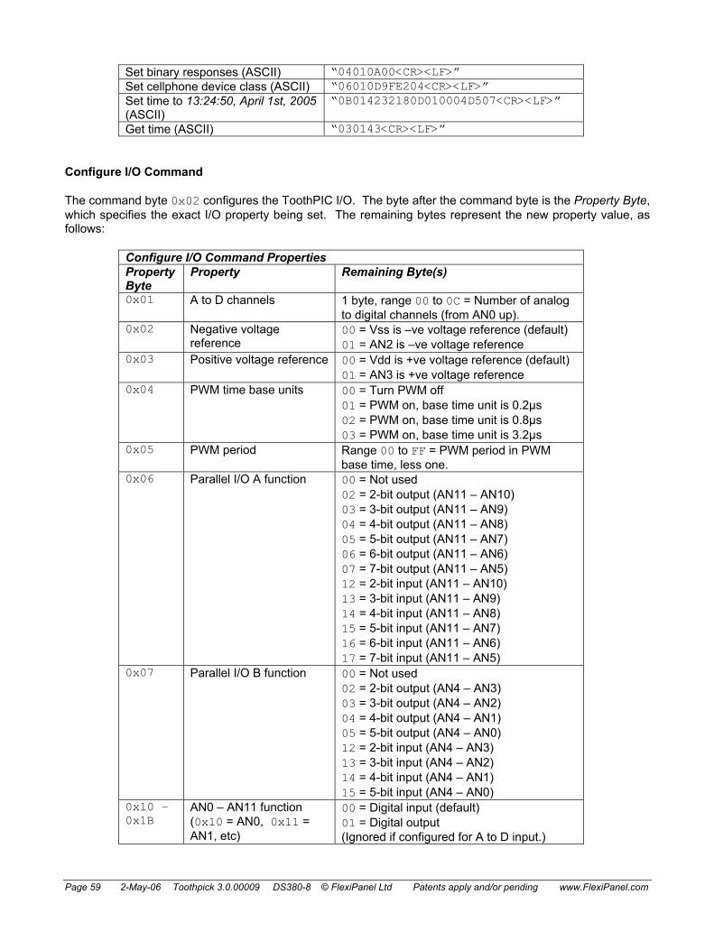
Page 59 2-May-06 Toothpick 3.0.00009 DS380-8 © FlexiPanel Ltd Patents apply and/or pending www.FlexiPanel.com
Set binary responses (ASCII) “04010A00<CR><LF>” Set cellphone device class (ASCII) “06010D9FE204<CR><LF>” Set time to 13:24:50, April 1st, 2005 (ASCII)
“0B014232180D010004D507<CR><LF>”
Get time (ASCII) “030143<CR><LF>”
Configure I/O Command
The command byte 0x02 configures the ToothPIC I/O. The byte after the command byte is the Property Byte, which specifies the exact I/O property being set. The remaining bytes represent the new property value, as follows:
Configure I/O Command Properties Property Byte
Property Remaining Byte(s)
0x01 A to D channels 1 byte, range 00 to 0C = Number of analog to digital channels (from AN0 up).
0x02 Negative voltage reference
00 = Vss is –ve voltage reference (default) 01 = AN2 is –ve voltage reference
0x03 Positive voltage reference 00 = Vdd is +ve voltage reference (default) 01 = AN3 is +ve voltage reference
0x04 PWM time base units 00 = Turn PWM off 01 = PWM on, base time unit is 0.2µs 02 = PWM on, base time unit is 0.8µs 03 = PWM on, base time unit is 3.2µs
0x05 PWM period Range 00 to FF = PWM period in PWM base time, less one.
0x06 Parallel I/O A function 00 = Not used 02 = 2-bit output (AN11 – AN10) 03 = 3-bit output (AN11 – AN9) 04 = 4-bit output (AN11 – AN8) 05 = 5-bit output (AN11 – AN7) 06 = 6-bit output (AN11 – AN6) 07 = 7-bit output (AN11 – AN5) 12 = 2-bit input (AN11 – AN10) 13 = 3-bit input (AN11 – AN9) 14 = 4-bit input (AN11 – AN8) 15 = 5-bit input (AN11 – AN7) 16 = 6-bit input (AN11 – AN6) 17 = 7-bit input (AN11 – AN5)
0x07 Parallel I/O B function 00 = Not used 02 = 2-bit output (AN4 – AN3) 03 = 3-bit output (AN4 – AN2) 04 = 4-bit output (AN4 – AN1) 05 = 5-bit output (AN4 – AN0) 12 = 2-bit input (AN4 – AN3) 13 = 3-bit input (AN4 – AN2) 14 = 4-bit input (AN4 – AN1) 15 = 5-bit input (AN4 – AN0)
0x10 – 0x1B
AN0 – AN11 function (0x10 = AN0, 0x11 = AN1, etc)
00 = Digital input (default) 01 = Digital output (Ignored if configured for A to D input.)

Page 60 2-May-06 Toothpick 3.0.00009 DS380-8 © FlexiPanel Ltd Patents apply and/or pending www.FlexiPanel.com
Configure I/O Command Properties Property Byte
Property Remaining Byte(s)
0x1C – 0x20
CCP1 – CCP5 function 00 = Digital input (default) 01 = Digital output 02 = PWM output
0x21 – 0x22
INT0 – INT1 function 00 = Digital input (default) 01 = Digital output
0x23 SCL function As INT0 0x24 SDA function As INT0 0x25 SDO function As INT0
Notes:
I/O pin functions: Pin specifications are ignored for AN inputs if the A to D channels property dictates that they should be A to D inputs. I/O pin functions must not be sent for pins used for parallel I/O, external memory and flow control purposes.
Parallel I/O: Pins are modified or read at exactly the same instant.
PWM base time units: Base time units for PWM values. PWM period is in PWM base time units (1 to 256). PWM duty cycle is in quarter PWM base time units (0 to 1023). PWM time base units turns PWM outputs on or off, so during initialization, set up period and initial output values first.
Configure I/O Command Examples Set AN0 – AN4 as A to D pins (binary) 0x04 0x02 0x01 0x05 Set AN0 – AN4 as A to D pins (ASCII) “04020105<CR><LF>” Set: PWM time base 3.2µs PWM period as 256 (=1220Hz) CCP2 pin as PWM (binary)
0x04 0x02 0x04 0x03 0x04 0x02 0x05 0xFF 0x04 0x02 0x1D 0x02
Set I/O Command
The command byte 0x03 sets a ToothPIC I/O output value. The byte after the command byte is the Property Byte, which specifies the exact I/O value being set. The remaining bytes represent the new I/O value, as follows:
Set I/O Command Properties Property Byte Property Remaining Byte(s) 0x06 Parallel I/O A output Range 00 to 7F = new value 0x07 Parallel I/O B output Range 00 to 1F = new value 0x10 – 0x1B AN0 – AN11 output 00 = low
01 = high 0x1C – 0x20 CCP1 – CCP5 output If digital, as AN0 – AN11.
If PWM, range 0000 to 03FF. (Both bytes must be specified.)
0x21 – 0x22 INT0 – INT1 output As AN0 0x23 SCL output As AN0 0x24 SDA output As AN0 0x25 SDO output As AN0 0x30 Green LED 00 = off
01 = on 0x31 Red LED 00 = off
01 = on

Page 61 2-May-06 Toothpick 3.0.00009 DS380-8 © FlexiPanel Ltd Patents apply and/or pending www.FlexiPanel.com
If the pin is not already configured as an output, the value will be ignored. I/O pin value commands must not be sent for pins used for external memory and flow control purposes.
Set I/O Command Examples Set AN10 as high (binary) 0x04 0x03 0x1A 0x01 Set AN10 as high (ASCII) “04031A01<CR><LF>” Set CCP2 as 33% duty cycle (binary) 0x04 0x03 0x1D 0x01 0x55
Get I/O Command
The command byte 0x04 requests a ToothPIC I/O value. The byte after the command byte is the Property Byte, which specifies the exact I/O value being requested. The value will be read and transmitted as an I/O value response.
Get I/O Command Properties Property Byte Property 0x06 Parallel I/O A input 0x07 Parallel I/O B input 0x10 – 0x1B AN0 – AN11 input 0x1C – 0x20 CCP1 – CCP5 input 0x21 – 0x22 INT0 – INT1 input 0x23 SCL input 0x24 SDA input 0x25 SDO input 0x30 Green LED 0x31 Red LED 0x32 Pushbutton
If the pin is configured as digital output, the result will be the current output value. If the pin is configured as CCP output, the result will be unpredictable. I/O pin value commands must not be sent for pins used for external memory and flow control purposes.
Get I/O Command Examples Get AN10 (binary) 0x03 0x04 0x1A Get AN10 (ASCII) “03041A<CR><LF>” Get CCP2 (binary) 0x03 0x04 0x1D
BlueMatik Command
The command byte 0x05 is for the BlueMatik Commands, which are sent directly to the Bluetooth radio. They allow device discovery, connection, transmission of raw data etc. The byte after the command byte is the Property Byte, which specifies the BlueMatik Property being modified. The remaining bytes represent any data associated with the command.
BlueMatik Command Properties Property Byte
Property Remaining Byte(s)
0x01 Enter slave mode None 0x02 Connect in master mode 6-byte Bluetooth device ID to connect to 0x03 Disconnect None 0x04 Inquire 1 byte inquiry duration in seconds, range
0x02 to 0x3C 0x06 Enquire link quality None 0x07 Enquire signal strength None 0x08 Enter sniff mode None

Page 62 2-May-06 Toothpick 3.0.00009 DS380-8 © FlexiPanel Ltd Patents apply and/or pending www.FlexiPanel.com
BlueMatik Command Properties Property Byte
Property Remaining Byte(s)
0x09 Exit sniff mode None 0x0A Enter hold mode None 0x0B Cancel None 0x10 Transmit raw data Up to 19 bytes of raw data
Notes:
Enter Slave Mode: Device becomes discoverable and connectable. The immediate response will be an OK response. When a device connects, a Connect Bluematik Response will be generated.
Connect in Master Mode: Device looks for a specific device to connect to. The immediate response will be an OK response. When a device connects, a Connect Bluematik Response will be generated. If no connect response is generated, the device is not found and you should issue a Cancel command.
Cancel: Cancels a Slave, Master or Inquiry command which has not yet completed connecting / inquiry.
For further information: The BlueMatik commands are discussed in detail in the ToothPIC Services reference.
FlexiPanel Server Commands
The command byte 0x06 is for the FlexiPanel Server Commands, which are sent directly to the FlexiPanel Server. They control the FlexiPanel User Interface service provided by ToothPIC. The user interface must first be programmed from FlexiPanel Designer as described in the above section Adding a FlexiPanel User Interface.
BlueMatik commands and FlexiPanel commands cannot be intermixed. BlueMatik must be idle when the FlexiPanel service is started and no further BlueMatik commands may be sent until after the Finish command has been sent.
The byte after the command byte is the Property Byte, which specifies the FlexiPanel Server Property being modified. The remaining bytes represent any data associated with the command.
FlexiPanel Server Properties Property Byte
Property Remaining Byte(s)
0x01 Start FlexiPanel service None 0x02 Finish FlexiPanel service None 0x03 Set Dialog 1 byte new dialog index number 0x04 Disconnect None 0x09 Initialize Data None
Notes:
Set Dialog: Displays a particular dialog. Dialogs are indexed in the order in which they are listed in FlexiPanel Designer, starting from 0x00.
Disconnect: Disconnects a particular client but does not end FlexiPanel service. Another client may connect.
Initialize Data: Data will already be initialized when the FlexiPanel service starts. This command allows the initial settings to be restored.

Page 63 2-May-06 Toothpick 3.0.00009 DS380-8 © FlexiPanel Ltd Patents apply and/or pending www.FlexiPanel.com
User Interface Info Commands
The command byte 0x07 is for the User Interface Info, which allows the host to read information about the user interface which has been programmed into ToothPIC by FlexiPanel Designer. The user interface must first be programmed from FlexiPanel Designer as described in the above section Adding a FlexiPanel User Interface.
The byte after the command byte is the Property Byte, which specifies the User Interface Info Property being modified. The remaining bytes represent any data associated with the command. Each general and dialog info commands will receive one User Interface Info Response; control info commands will receive two. Note that since the ToothPIC Slave firmware solution does not know in advance what the user interface looks like, if you ask a meaningless question you may get a meaningless response rather than an error.
User Interface Info Properties Property Byte
Property Remaining Byte(s)
0x01 General Info None 0x02 Dialog Info Dialog index 0x03 Control Info Control ID
Note: The two bytes after the command byte are the Control ID. This is the value displayed in FlexiPanel Designer under heading ID in the main controls list. Beware that this ID may change if you insert a dialog or a control earlier in the control list. You may therefore wish to define constants in your host controller code to simplify changes to ID values.
Get Control Data Command
The Get Control Data Command byte 0x08 retrieves the value of a control. The user interface must first be programmed from FlexiPanel Designer as described in the above section Adding a FlexiPanel User Interface. The FlexiPanel Server does not need to be running in order to get or set values.
The two bytes after the command byte are the Control ID. This is the value displayed in FlexiPanel Designer under heading ID in the main controls list. Beware that this ID may change if you insert a dialog or a control earlier in the control list. You may therefore wish to define constants in your host controller code to simplify changes to ID values.
Each Get Control Data Command will receive at least one Control Data Response. If the storage required for the control is greater than 16 bytes, multiple Control Data Response bytes will be received.
Get Control Data Command Examples Get control 0x1234 (binary) 0x04 0x08 0x12 0x34 Get control 0x1234 (ASCII) “04081234<CR><LF>”
Set Control Props Command
The Set Control Props Command byte 0x09 sends control properties information to the client. Properties are modified on the client only, not in the server. A client must therefore be connected for these properties to take effect. When a new client connects, the properties will have to be sent again.
The entire command is always 12 bytes long. The two bytes after the command byte are the Control ID. This is the value displayed in FlexiPanel Designer under heading ID in the main controls list. Beware that this ID may change if you insert a dialog or a control earlier in the control list. You may therefore wish to define constants in your host controller code to simplify changes to ID values.
The subsequent 4 bytes of the command specify the new properties. The following properties may be bitwise-ORed together:

Page 64 2-May-06 Toothpick 3.0.00009 DS380-8 © FlexiPanel Ltd Patents apply and/or pending www.FlexiPanel.com
Properties of Message Controls (A message can only be displayed if its dialog is visible.) To display a message control 0x00 0x00 0x00 0x00
To modify the message control’s properties without displaying it.
0x01 0x00 0x00 0x00
No icon 0x00 0x00 0x01 0x00 Stop icon 0x00 0x00 0x02 0x00 Exclamation icon 0x00 0x00 0x03 0x00 Question icon 0x00 0x00 0x04 0x00 Information icon 0x00 0x00 0x05 0x00 No button response message required 0x00 0x00 0x00 0x00 OK button (V3 clients only) 0x00 0x00 0x10 0x00 OK, Cancel buttons (V3 clients only) 0x00 0x00 0x20 0x00 Retry, Cancel buttons (V3 clients only) 0x00 0x00 0x30 0x00 Yes, No buttons (V3 clients only) 0x00 0x00 0x40 0x00 Yes, No, Cancel buttons (V3 clients only) 0x00 0x00 0x50 0x00 Abort, Retry, Ignore buttons (V3 clients only) 0x00 0x00 0x60 0x00
Properties of Other Controls Ensure control is visible on client screen 0x10 0x00 0x00 0x00 If the control color properties are to be set 0x40 0x00 0x00 0x00
The final 4 bytes of the command specify the new control color. The RGB values, each in the range 0x00 to 0xFF, are sent as the bytes 0xRR 0xGG 0xBB 0x00.
Set Control Properties Command Examples Show a message control 0x0B03, info icon, Yes / No buttons (binary)
0x0C 0x09 0x0B 0x03 0x00 0x45 0x00 0x00 0x00 0x00 0x00 0x00
Make control 0x0003 onscreen and red.
0x0C 0x09 0x00 0x03 0x50 0x00 0x00 0x00 0xFF 0x00 0x00 0x00
Set Control Data Command
The Set Control Data Command byte 0x0A sets the value of a control. The user interface must first be programmed from FlexiPanel Designer as described in the above section Adding a FlexiPanel User Interface. The FlexiPanel Server does not need to be running in order to get or set values. For matrix controls, one of the Set / Append / Log Row commands is preferred.
The two bytes after the command byte are the Control ID. This is the value displayed in FlexiPanel Designer under heading ID in the main controls list. Beware that this ID may change if you insert a dialog or a control earlier in the control list. You may therefore wish to define constants in your host controller code to simplify changes to ID values.
The next two bytes are the control offset (little-endian) and the remaining bytes are the new control data. For controls whose data length is 16 bytes or less, the control offset should be zero. For controls whose length is 17 bytes or greater, it will be necessary to update the data using multiple Set Control Data Commands, each with different control offset values. The control offset indicates where the new control data are to be placed within the control’s data field. If multiple Set Control Data Commands are sent for a control, ensure that the last, and only the last, has a control offset of zero. This indicates that the control data update is complete and the new data can be transmitted to the client.
The data types for the various controls are as follows:
Control Data Types Control Data type description.

Page 65 2-May-06 Toothpick 3.0.00009 DS380-8 © FlexiPanel Ltd Patents apply and/or pending www.FlexiPanel.com
Control Data Types Control Data type description. Blob Binary data object – size specified in FlexiPanel Designer. Button No data. Date-Time 8-byte DateTimeU data structure. Files No data. Image No data. Latch 1 byte, 0x00 for off, 0xFF for on. List 4 bytes, little-endian, zero-based index of the selected item. Matrix Extensive – see ToothPIC Services Reference. Message No data. Number 4 bytes, little-endian, signed integer. Password 1 byte, 0x00 for closed, 0xFF for open. Section 1 byte, 0x00 for closed, 0xFF for open. Text ASCII or Unicode text – size specified in FlexiPanel Designer.
Set Control Data Command Examples Set list or number control 0x0002 to the value 0x00000005
0x0A 0x0A 0x00 0x02 0x00 0x00 0x05 0x00 0x00 0x00
Set text control 0x0705 to the value “ABCDEFGHIJKLMNOPQRSTUVWXYZ” Note zero terminator and little-endian offset value. First 16 bytes sent last to ensure that all control data are updated on the client simultaneously.
0x11 0x0A 0x07 0x05 0x10 0x00 0x51 0x52 0x53 0x54 0x55 0x56 0x57 0x58 0x59 0x5A 0x00 0x16 0x0A 0x07 0x05 0x00 0x00 0x41 0x42 0x43 0x44 0x45 0x46 0x47 0x48 0x49 0x4A 0x4B 0x4C 0x4D 0x4E 0x4F 0x50
Set Row Command
The Set Row Data Command byte 0x0B sets a single row of data on a matrix control. The user interface must first be programmed from FlexiPanel Designer as described in the above section Adding a FlexiPanel User Interface. The FlexiPanel Server does not need to be running in order to get or set values.
The two bytes after the command byte are the matrix Control ID. This is the value displayed in FlexiPanel Designer under heading ID in the main controls list. Beware that this ID may change if you insert a dialog or a control earlier in the control list. You may therefore wish to define constants in your host controller code to simplify changes to ID values.
The next two bytes are the row number to be set (little-endian). The first row is row zero. No row should be set unless all row numbers preceding have been previously set. The Set Row Command should not be given on any matrix which has previously received an Append Row or Log Row command.
If the matrix is a Date-Time matrix, the next 8 bytes are the date-time axis data; otherwise, if it is an XY matrix with n bytes per X-axis value, the next n bytes are the X-axis data.
The remaining rows are the data for each cell in the row. The number of bytes of data should equal the number of bytes per cell multiplied by the number of columns.
Unlike the Append Row and Log Row commands, it is quite probable that you will wish to update more than one row at a time, and only transmit the result to the client when all rows have been updated. For this reason, the client is not updated unless a Set Row command is sent containing no X or Y or row index data (i.e. just the first four bytes of the command).

Page 66 2-May-06 Toothpick 3.0.00009 DS380-8 © FlexiPanel Ltd Patents apply and/or pending www.FlexiPanel.com
Set Row Command Example (X Axis is 2 bytes, 3 columns of 1 byte each) Set matrix 0x0002 row 6 to (X=33, 6, 7, 8) 0x0B 0x0B 0x00 0x02 0x06 0x00
0x21 0x00 0x06 0x07 0x08 Set matrix 0x0002 row 4 to (X=22, 3, 4, 5) 0x0B 0x0B 0x00 0x02 0x04 0x00
0x16 0x00 0x06 0x07 0x08 Send result to client 0x04 0x0B 0x00 0x02
Append Row Command
The Append Row Data Command byte 0x0C appends a row onto the end of a matrix control. The user interface must first be programmed from FlexiPanel Designer as described in the above section Adding a FlexiPanel User Interface. The FlexiPanel Server does not need to be running in order to get or set values.
The two bytes after the command byte are the matrix Control ID. This is the value displayed in FlexiPanel Designer under heading ID in the main controls list. Beware that this ID may change if you insert a dialog or a control earlier in the control list. You may therefore wish to define constants in your host controller code to simplify changes to ID values.
The row data will be appended onto the bottom of the matrix. If the matrix is full, the top row will be discarded.
If the matrix is a Date-Time matrix, the next 8 bytes are the date-time axis data; otherwise, if it is an XY matrix with n bytes per X-axis value, the next n bytes are the X-axis data.
The remaining rows are the data for each cell in the row. The number of bytes of data should equal the number of bytes per cell multiplied by the number of columns.
The updated row will be immediately transmitted to the client, if connected.
Append Row Command Example (X Axis is 2 bytes, 3 columns of 1 byte each) Append (X=33, 6, 7, 8) to matrix 0x0002
0x09 0x0C 0x00 0x02 0x21 0x00 0x06 0x07 0x08
Log Row Command
The Log Row Data Command byte 0x0D appends a row onto the end of a Date-Time matrix control, using the current value of the real time clock as the Date-Time axis data. The user interface must first be programmed from FlexiPanel Designer as described in the above section Adding a FlexiPanel User Interface. The FlexiPanel Server does not need to be running in order to get or set values.
The two bytes after the command byte are the matrix Control ID. This is the value displayed in FlexiPanel Designer under heading ID in the main controls list. Beware that this ID may change if you insert a dialog or a control earlier in the control list. You may therefore wish to define constants in your host controller code to simplify changes to ID values.
The row data will be appended onto the bottom of the matrix. If the matrix is full, the top row will be discarded.
The remaining rows are the data for each cell in the row. The number of bytes of data should equal the number of bytes per cell multiplied by the number of columns.
The updated row will be immediately transmitted to the client, if connected.
Log Row Command Example (X Axis is date-time, 3 columns of 1 byte each) Append (6, 7, 8) to matrix 0x0002 0x07 0x0D 0x00 0x02 0x06 0x07 0x08

Page 67 2-May-06 Toothpick 3.0.00009 DS380-8 © FlexiPanel Ltd Patents apply and/or pending www.FlexiPanel.com
Get Memory Command
The Get Memory Data Command byte 0x0E retrieves data from internal or external memory. Very little error checking is done with this command, so it should be used with care.
The byte after the command byte is the mStr memory storage type as defined in the Memory Management section of the ToothPIC Services Reference. The next two bytes are the Addr memory address (little-endian) as defined in the Memory Management section of the ToothPIC Services Reference.
The final byte is the number of bytes required, up to 17 bytes.
Each Get Memory Command will receive exactly one Got Memory Response.
Get Control Data Command Example Get 4 bytes of EE memory from 0x0123 0x06 0x0E 0x03 0x23 0x01 0x04
Set Memory Command
The Set Memory Data Command byte 0x0F sets data in internal or external memory. Very little error checking is done with this command, so it should be used with care. It is your responsibility to ensure that you do not overwrite important memory regions. Overwriting ROM00 locations is not permitted; neither is writing to ROM01 location 0xE000 or higher.
The byte after the command byte is the mStr memory storage type as defined in the Memory Management section of the ToothPIC Services Reference. The next two bytes are the Addr memory address (little-endian) as defined in the Memory Management section of the ToothPIC Services Reference.
The remaining bytes are the data to be written to memory mStr starting at location Addr. Up to 17 bytes may be written per Set Memory command.
Set Memory Command Example Set EE memory from 0x0123 with the values 0x05 0x06 0x07 0x08.
0x09 0x0F 0x03 0x23 0x01 0x05 0x06 0x07 0x08
Memory Map
The following memory areas are accessible:
Type mStr value
Lower address
limit
Upper address
limit
Also used by
RAM (volatile) 0x02 0x100 0x8FF User interface (from 0x100 up). Message queue (from 0x8FF down).
EE 0x03 0x000 0x3FF User interface (from 0x0000 up). Configuration settings 0x3E0-0x3FF
EXT0 external memory (I2C addr 0xB0/0xB1)
0x10 0x0000 IC limit User interface (from 0x0000 up).
EXT1 external memory (I2C addr 0xB2/0xB3)
0x11 0x0000 IC limit User interface (from 0x0000 up).
EXT2 external memory (I2C addr 0xB4/0xB5)
0x12 0x0000 IC limit User interface (from 0x0000 up).
EXT3 external memory (I2C addr 0xB6/0xB7)
0x13 0x0000 IC limit User interface (from 0x0000 up).

Page 68 2-May-06 Toothpick 3.0.00009 DS380-8 © FlexiPanel Ltd Patents apply and/or pending www.FlexiPanel.com
Type mStr value
Lower address
limit
Upper address
limit
Also used by
EXT4 external memory (I2C addr 0xB8/0xB9)
0x14 0x0000 IC limit User interface (from 0x0000 up).
EXT5 external memory (I2C addr 0xBA/0xBB)
0x15 0x0000 IC limit User interface (from 0x0000 up).
EXT6 external memory (I2C addr 0xBC/0xBD)
0x16 0x0000 IC limit User interface (from 0x0000 up).
EXT7 external memory (I2C addr 0xBE/0xBF)
0x17 0x0000 IC limit User interface (from 0x0000 up).
Upper ROM block (0x01xxxx)
0x81 0x0000 0xDFFF User interface (from 0x0000 up).
This memory is free for you to use, other than as follows:
• Designer.exe requires memory for the user interface as specified at the beginning of the computer-generated file it creates.
• RAM locations from 0x8FF downwards are used by the message queue, 0x16 bytes per message. For example, by default, 0x20 messages can be queued, so 0x640 to 0x8FF are used for the message queue.
• EE locations 0x3E0 to 0x3FF are used to store configuration settings.
If your user interface uses a large quantity of EE or RAM memory, you must also take care that you do not overwrite the message queue or the configuration settings. FlexiPanel Designer down not know these are already allocated and it will not warn you about this.
You can inspect values outside the address limits specified. However, writing to these addresses may cause the ToothPIC to malfunction.
Breakpoint Command
The command byte 0x10 instructs the ToothPIC to flash its LEDs, allowing the host to indicate that an error has occurred. It there is no response and no further commands should be sent without resetting the ToothPIC.
The byte after the command byte is a FlashVal value. This value is used to control how the LEDs flash. The number is flashed as follows:
- As many green and red simultaneous flashes as the hundreds digit of FlashVal
- As many red flashes as the tens digit of FlashVal
- As many green flashes as the units digit of FlashVal
or
- Three green and red simultaneous flashes if FlashVal is zero
Breakpoint Command Examples Flash 201 (binary) 0x03 0x10 0xC9

Page 69 2-May-06 Toothpick 3.0.00009 DS380-8 © FlexiPanel Ltd Patents apply and/or pending www.FlexiPanel.com
Get Message Command
The command byte 0x40 instructs the ToothPIC to send the next response in the queue, presuming the Responses anytime property is not set. If there are no more responses, the OK response will be sent.
Get Message Command Examples Get Message (binary) 0x02 0x40 Get Message (ASCII) “0240<CR><LF>”
Responses
Binary responses may be up to 22 bytes long; ASCII responses 48 bytes. The first byte is the response length byte, equal to the total number of bytes in the message. The second byte is the response byte, which indicates how the remainder of the message should be interpreted.
Responses may be in either ASCII or binary as specified by the ASCII responses property. In ASCII format, each byte is transmitted as two hexadecimal digits and the entire command will be preceded and followed by a <CR><LF> pair (i.e. the control characters 0x0D and 0x0A).
If the Responses anytime property is set, all commands generate a response. This will be the OK response if no other response is appropriate.
Some responses are unsolicited (see following table). If you put ToothPIC into a state where an unsolicited message may be generated, be warned that it may occur at any time. In particular, do not assume that a message sent to ToothPIC will be immediately responded to with the response to that message; unsolicited responses may be received first.
Command Summary Response (* = unsolicited)
Response Byte
Interpretation
OK 0x01 Acknowledges completion of previous command Error (*) 0x02 Reports an error. (Can be unsolicited depending on
On internal error… configuration setting.) Date Time 0x03 Reports the time and date I/O Value 0x04 The value of the requested I/O pin BlueMatik Response*
0x05 The BlueMatik radio reports that an event occurred
FlexiPanel Response*
0x06 The FlexiPanel server reports that an event occurs
User Info 0x07 The value of the requested user interface information Control Data 0x08 The value of the requested control Got Memory 0x09 The value of the requested memory location Initialization* 0x53 A message sent to indicate initialization is complete
OK Response
The response byte 0x01 indicates that the previous command has been processed and another command may be sent.
OK Response Examples OK (binary) 0x02 0x01 OK (ASCII) “<CR><LF>0201<CR><LF>”

Page 70 2-May-06 Toothpick 3.0.00009 DS380-8 © FlexiPanel Ltd Patents apply and/or pending www.FlexiPanel.com
Error Response
The response byte 0x02 indicates that an error has occurred. The byte after the response byte is the Error Byte, which specifies the exact error that occurred:
Error Response Error Values Error Byte Error Name Interpretation 0xF0 Queue full The message queue filled up and some
messages were lost 0xF1 Not understood The previous command was not understood 0xF2 Ping Fail A FxPE_PingFail ping failure occurred
In addition, if the On internal error… property specifies that internal errors should be reported to the host, the error byte may equal any of the ErrorStatus, BMTE_Error, BMTE_Warning error values.
Error Response Examples Queue full (binary) 0x03 0x02 0xF0 Not understood (ASCII) “<CR><LF>0302F1<CR><LF>” ErrorStatus error Memory Failure (binary)
0x03 0x02 0x0B
General BlueMatik error (ASCII)
“<CR><LF>03020F<CR><LF>”
Date Time Response
The response byte 0x03 reports the current date and time to the host. The 8 bytes after the response byte are the date and time in DateTimeU format.
Date Time Response Examples – 13:24:50, Friday, April 1st, 2005 Date Time (binary) 0x0A 0x03 0x32 0x18 0x0D 0x01 0x05 0x04
0xD5 0x07 Date Time (ASCII) “<CR><LF>0A0332180D010504D507<CR><LF>”
I/O Value Response
The response byte 0x04 reports an I/O input value to the host. The first byte after the response byte indicates which value is being reported and matches those used in the Get I/O Command. The remaining byte(s) will contain the reported value. The size will vary according to data type as shown in the examples below.
I/O Value Response Examples SDO digital input high (binary) 0x04 0x04 0x25 0x01 SDO digital input low (ASCII) “<CR><LF>04042500<CR><LF>” AN3 analog input 0x234 (range 0 to 1023) (ASCII)
“<CR><LF>0504130234<CR><LF>”
Parallel A (7-bit) analog input 0x14 (range 0 to 31) (ASCII)
“<CR><LF>04040614<CR><LF>”

Page 71 2-May-06 Toothpick 3.0.00009 DS380-8 © FlexiPanel Ltd Patents apply and/or pending www.FlexiPanel.com
BlueMatik Response
The response byte 0x05 reports a response from the BlueMatik radio. The first byte after the response byte is the Response Value that indicates which response is being reported. The remaining byte(s) will contain any associated data.
BlueMatik Responses Response Value
Response Meaning
Associated Data Interpretation
0x03 Connect 6-byte Bluetooth ID of remote device
A connection has been established.
0x04 Disconnect None The remote device terminated the connection
0x05 Found 6-byte Bluetooth ID of remote device, then first 12 bytes of name and zero terminator
A remote device was discovered during inquiry. (Ignore any data send after name zero terminator.)
0x06 Paired 6-byte Bluetooth ID of remote device
A remote device successfully paired with this device
0x07 LinkQ 1-byte link quality Response to link quality request 0x08 Signal 1-byte signal strength Response to signal strength request0x09 Low Power None The low power mode changed 0x10 Receive raw data Up to 19 bytes Raw data received
For more details on any of these responses, consult the BlueMatik Events section of the ToothPIC Services Reference section.
BlueMatik Response Examples Device 12:34:56:78:90:AB connected (ASCII)
“<CR><LF>0905031234567890AB<CR><LF>”
Link quality (Binary) 0x04 0x05 0x07 0xFF
FlexiPanel Server Response
The response byte 0x06 reports a response from the FlexiPanel Server. The first byte after the response byte is the Response Value that indicates which response is being reported. The remaining byte(s) will contain any associated data.
FlexiPanel Server Responses Response Value
Response Meaning
Associated Data Interpretation
0x01 Connect None A client connected 0x02 Disconnect None A client disconnected 0x04 Client Update 2-byte control ID Client modified a control 0x07 Message
Response 1-byte index number of response
The client selected an option in a message box. (V3 clients only)
For the Client Update message, the Control ID is the value displayed in FlexiPanel Designer under heading ID in the main controls list. Beware that this ID may change if you insert a dialog or a control earlier in the control list. You may therefore wish to define constants in your host controller code to simplify changes to ID values.
For more details on any of these responses, consult the FlexiPanel User Interface Server Events section of the ToothPIC Services Reference.
FlexiPanel Server Response Examples Device connected (ASCII) “<CR><LF>030601<CR><LF>”

Page 72 2-May-06 Toothpick 3.0.00009 DS380-8 © FlexiPanel Ltd Patents apply and/or pending www.FlexiPanel.com
Client modified control 0x0002 (Binary) 0x05 0x06 0x04 0x00 0x02
User Interface Info Response
The response byte 0x07 is a response to a User Interface Info command. The first byte after the response byte is the Response Value that indicates which response is being reported. The remaining byte(s) will contain associated data.
User Interface Info Responses Response Value
Response Meaning
Associated Data (2-byte integers except control ID are are little-endian.)
0x01 General Info First 16 bytes of bqFxPData data structure as described in ToothPIC.h
0x02 Dialog Info First byte is Dialog ID; then next 4 bytes are bqFxPDlgData data structure as described in ToothPIC.h
0x03 Control Info I First byte is Control ID; then next 4 bytes are bqFxPDlgData data structure as described in ToothPIC.h
0x04 Control Info II First byte is Control ID; then next 4 bytes are bqFxPDlgData data structure as described in ToothPIC.h
For the Client Update message, the Control ID is the value displayed in FlexiPanel Designer under the heading ID in the main controls list. Note that this ID may change if you insert a dialog or a control earlier in the control list. You may therefore wish to define constants in your host controller code to simplify changes to ID values.
Control Data Response
Control Data Response byte 0x08 is a response to a Get Control Data command. The two bytes after the response byte are the Control ID.
If the control value comprises more than 16 bytes, it will be necessary to send multiple control data response messages to convey the information. The two bytes after the Control ID are therefore the data offset (little-endian) of this particular response: 0x0000 for the first response, 0x0010 for the second and so on. The remaining byte(s) will contain associated data.
For the Client Update message, the Control ID is the value displayed in FlexiPanel Designer under the heading ID in the main controls list. Note that this ID may change if you insert a dialog or a control earlier in the control list. You may therefore wish to define constants in your host controller code to simplify changes to ID values.
The data types for the various controls are as follows:
Control Data Types Control Data type description. Blob Binary data object – size specified in FlexiPanel Designer. Button No data. Date-Time 8-byte DateTimeU data structure. Files No data. Image No data. Latch 1 byte, 0x00 for off, 0xFF for on. List 4 bytes, little-endian, zero-based index of the selected item. Matrix Extensive – see ToothPIC Services Reference. Message No data. Number 4 bytes, little-endian, signed integer. Password 1 byte, 0x00 for closed, 0xFF for open.

Page 73 2-May-06 Toothpick 3.0.00009 DS380-8 © FlexiPanel Ltd Patents apply and/or pending www.FlexiPanel.com
Control Data Types Section 1 byte, 0x00 for closed, 0xFF for open. Text ASCII or Unicode text – size specified in FlexiPanel Designer.
Got Memory Response
Control Data Response byte 0x09 is a response to a Get Memory Data command.
The byte after the command byte is the mStr memory storage type as defined in the Memory Management section of the ToothPIC Services Reference. The next two bytes are the Addr memory address (little-endian) as defined in the Memory Management section of the ToothPIC Services Reference.
The remaining bytes are the data read from memory mStr starting at location Addr, as requested
Got Memory Response Example Report EE memory from 0x0123 being values 0x05 0x06 0x07 0x08.
0x09 0x09 0x03 0x23 0x01 0x05 0x06 0x07 0x08
Initialization Response
The initialization response byte 0x53 indicates that the ToothPIC Slave has initialized correctly. The 16 bytes of the response including the response length byte will be comprised the of bytes 0x10, 0x53, 0x6E, 0x61, 0x76, 0x66, 0x20 followed by the ToothPIC Services version number as ASCII characters.
Initialization Response Examples – Version 3.0.00002 Initialization complete (binary)
0x10 then “Slave 3.0.00002”
Initialization complete (ASCII)
“<CR><LF>10536E61766620332E302E3030303032<CR><LF>”
Command / Response User Guide
The following tables of groups of commands and responses show how to achieve common tasks with ToothPIC Slave. The responses are examples and may differ.
Initialization Response Meaning 10536E61766620332E302E3030303032 Initialization successful, version 3.0.00002
Setting SDO as digital output Command Response Meaning 04022501 0201 Set SDO to output 04032501 0201 Set output value to high
Setting SDO as digital input Command Response Meaning 04022300 0201 Set SCL to input 030423 04042300 Get input value, result 0x00 = low

Page 74 2-May-06 Toothpick 3.0.00009 DS380-8 © FlexiPanel Ltd Patents apply and/or pending www.FlexiPanel.com
Setting CCP1 as CCP output Command Response Meaning 04020403 0201 Set PWM time base to 3.2µs 040205FF 0201 Set PWM period to (0xFF+1) x 3.2µs = 819.2µs (1220Hz) 04021C02 0201 Set CCP1 to PWM output 05031C01FF 0201 Set duty cycle to 0x01FF x (3.2µs / 4) = 408.8µs
Setting AN11 as analog input Command Response Meaning 04020102 0201 Set AN0 and AN1 as analog inputs 030411 05041103EB Read AN1
Setting AN11, AN10, AN9 as parallel output Command Response Meaning 04020603 0201 Set parallel output A to 3-bit 04030605 0201 Set output to 0x05 = 101 binary
Setting AN11, AN10, AN9 as parallel input Command Response Meaning 04020613 0201 Set parallel input A to 3-bit 030406 04040603 Read input value, result 0x03 = 011 binary
Bluetooth slave mode connection Command Response Meaning 030501 0201 Enters slave mode 090503080046B939B0 Remote device with ID 80:00:46:B9:39:B0
connects 08051048656C6C6F †Remote device sent ASCII Hello 030504 †Remote device disconnected
† Note that the master / slave distinction merely refers to which device establishes the connection. Both devices may send data to the other. Either device may choose to disconnect; in addition, automatic disconnection will occur if they go out of range of each other. BlueMatik commands generating an OK response (0201) should not be regarded as complete until the OK response is generated.
Bluetooth inquiry & master mode connection Command Response Meaning 0405040F (Busy - No immediate
response) Do device inquiry for 0x0F seconds
160505080046B939B0466C65786950616E656C205600
Remote device with ID 80:00:46:B9:39:B0 found, name begins “FlexiPanel”
16050500043E80C44B506F636B65745F504300656C00
Remote device with ID 80:00:46:B9:39:B0 found, name begins “Pocket_PC”
030504 End of device inquiry (command complete) 0905028000 46B939B0
090502800046B939B0 Connect to remote device with ID 00:04:3E:80:C4:4B; connection successful
0805104865 6C6C6F
0201 †Send ASCII “Hello” to remote device.
030506 0201 030507FF
Enquire link quality Quality is reasonably good
030503 030504 0201
†Disconnect from remote device

Page 75 2-May-06 Toothpick 3.0.00009 DS380-8 © FlexiPanel Ltd Patents apply and/or pending www.FlexiPanel.com
FlexiPanel Server (with PMTestRes.FxP User Interface loaded) Command Response Meaning 030601 0201 Start FlexiPanel UI Service 09050300043E80C44B BlueMatik reports remote device connected. 030601 FlexiPanel Service reports FlexiPanel Client
connected. Choose Test dialog displayed. (Choose Load Recommended Layout from menu if layout unusual.)
04060301 0201 Show dialog 0x01 (Test Real Time Clock) 0506040109 End test button (ID = 0x0109) pressed 030602 0201
030504 End FlexiPanel service. BlueMatik reports client disconnecting
User Interface Info (with PMTestRes.FxP User Interface loaded) Command Response Meaning 030701 1307011002AA0006000
ABA6000450888420000User interface general information
04070202 0707020D0004BA User interface dialog 0x02 information 0507030204 130703000100FF4001F
FFF000100FF10013A01 0F0704000100FF00011900000100FF
User interface control 0x0204 information Response part I Response part II
Control Data Responses (with PMTestRes.FxP User Interface loaded) Command Response Meaning 04080102 0E080102000000
36160D020CD407 Fixed date-time control 0x0102 initial value (8 bytes of data)
04080101 1608010100005465737420 5265616C2054696D652043 0B08010110006C6F636B00
Control 0x0101 (“Test real time clock”) text; first 16 bytes of ASCII text Remaining bytes of ASCII text

Page 76 2-May-06 Toothpick 3.0.00009 DS380-8 © FlexiPanel Ltd Patents apply and/or pending www.FlexiPanel.com
Guide To MPLAB C18 Development The developer should be proficient in developing C applications for PIC18 series devices using MPLAB and C18 before expecting to benefit from this section.
Development Environment
The MPLAB development environment and C18 compiler must be obtained separately from Microchip Technology Inc or one of its distributors.
A debugger or programmer will also be required. For product development, the Microchip ICD-2 in-circuit debugger is recommended. For programming, the following connections must be made between the ICD2 debugger and ToothPIC:
ToothPIC pin ICD2 Connection
Vss Vss Vdd Vdd
NMCLR NMCLR INT0/PGC PGC INT1/PGD PGD
The cable from the debugger to the ToothPIC needs to be short. An adapter cable is available for connecting directly from the ICD2 to a ToothPIC plugged into a breadboard – see the Ordering Information section.
1. Starting Point Selection
Choose the Firmware Solution which is closest to the application you wish to develop. Use the Hello World example if none of the others are appropriate.
Make sure you can successfully compile the source code and load it into ToothPIC before proceeding to step 2.
If you prefer to start a new project rather than working from a firmware solution, be sure to specify:
• HS oscillator configuration • Watchdog timer off • Watchdog timer postscaler 1:128 • Power-up timer on • Oscillator switch enabled • CCP2 Mux RE7
• Table Write Protect 00200-03FFF enabled
• Table Write Protect 04000-08FFF enabled
• Table Write Protect 08000-0BFFF enabled
• Table Write Protect 00000-001FF enabled
• Large Code Model • Large Data Model • Multi-Bank Stack Model
2. User Interface Design
If the FlexiPanel User Interface server is used, the user interface dialogs should be designed using FlexiPanel Designer. Do this first to ensure the interface is user-friendly.
Assuming you are modifying the source code for an existing Firmware Solution, start with the .FxP source file for that solution. The output of FlexiPanel Designer will be a .c source file and a .h header file, plus a .hex data file if external memory is used.
3. Project Building
Create an MPLAB project including the following files:
• The .c and .h files generated by FlexiPanel Designer, if applicable.
• The file ToothPIC.h, which assists in linking to the ToothPIC Services.
• The file ToothPIC303.c which contains the user-modifiable portion of the ToothPIC Services.
• The file ToothPIC304.lib which contains the proprietary portion of the ToothPIC Services.
• The file ToothPicMath304.o which contains the math functions which must be resident in the protected ToothPIC services memory area.
• The stack and data initialization code c018ibk.c only if you need to make modifications to it. If you omit it, the linker will use the standard initialization code c018ibk.o provided in ToothPIC304.lib.

Page 77 2-May-06 Toothpick 3.0.00009 DS380-8 © FlexiPanel Ltd Patents apply and/or pending www.FlexiPanel.com
• The linker script ToothPIC304.lkr, which allocates memory, including that required for in-circuit debugging if needed.
• Application-specific .c and .h files, e.g. those that come with a specific Firmware Solution.
4. Application-Specific Coding
Write or modify the application-specific program. The following functions must be provided, even if they return immediately:
main(), the execution entry point HiInterrupt(), the fast interrupt handler LoInterrupt(), the slow interrupt handler ErrorStatus(), the Services error callback BMEvent(), the BlueMatik callback FxPEvent(), the FlexiPanel UI callback
5. ToothPIC Programming
ToothPIC is programmed with the executable code, either using the Wireless Field Programmer or using MPLAB with a conventional in-circuit programming device such as the ICD-2 debugger.
Once the developer function main() begins, events may interrupt control-of-flow, such as data being received via Bluetooth. Therefore developer-code execution times are not
guaranteed unless interrupts are suspended. Equally, callbacks may occur at any time during the normal flow of developer code. Therefore the use of Semaphores should be clearly understood. Refer to the Semaphores, sub-section of the ToothPIC Services Reference.
6. Debugging
The code is debugged using an in-circuit debugger such as MPLAB ICD-2.
• During debugging, remember that time-critical events may be missed if a breakpoint is reached. In particular, any serial data sent from BlueMatik will then be lost. At the very least, disable pings if you are using the FlexiPanel Server to stop the client from disconnecting.
7. Production Programming
Wireless Field Programming or conventional in-circuit programming may be used in production. For low-volume production, Wireless Field Programming avoids the need for a programming connector. In high volumes (>100 units per order), FlexiPanel Ltd can supply ToothPIC pre-loaded with your code as required.

Page 78 2-May-06 Toothpick 3.0.00009 DS380-8 © FlexiPanel Ltd Patents apply and/or pending www.FlexiPanel.com
Designing User Interfaces
Refer to the DARC-II Firmware Solution for a graphical tutorial on the FlexiPanel Designer software.
FlexiPanel User Interfaces are designed with FlexiPanel Designer. This is software freely available from www.FlexiPanel.com. FlexiPanel Designer can also simulate user interfaces on remote client devices.
This section provides an overview of the user interface designs possible with ToothPIC. For full details, consult the FlexiPanel Designer software documentation.
If a custom application is being developed using MPLAB C18 then the user interface is transferred to ToothPIC as computer-generated C files which are included during compilation.
If a user interface is being developed for a Firmware Solution such as the Serial Adapter or DARC module, it is programmed directly from FlexiPanel Designer into ToothPIC using a Bluetooth connection.
FlexiPanel Bluetooth Protocol
FlexiPanel client devices can connect to the FlexiPanel BASIC Stamp Programmer (the ‘Server’) at any time. Once connected, the server tells the client to show the user interface on its display. Both the client and the BASIC Stamp can modify the user interface controls at any time.
The client or ToothPIC may choose to disconnect. Additionally, the link may be dropped if the devices go out of range of each other. The state of the controls is retained by the server so that if the client reconnects, or another client connects, the control panel will be in the same state as it was when it was last modified.
Devices incorporating FlexiPanel Servers must be designed taking into account the possibility of a dropped connection. Specifically, no action should be taken which relies on a client’s ability to maintain a connection. If FlexiPanel is used to operate machinery, for example, the ToothPIC should provide a failsafe mode in case the connection is dropped.
The communication standard used by ToothPIC in order to communicate with clients is FlexiPanel Protocol 3.0. Some client software may use
FlexiPanel Protocol 2.3, which cannot display Image controls.
Introduction to FlexiPanel Controls
A variety of control types are provided by FlexiPanel. These include controls familiar to Windows users and others that are particularly appropriate for FlexiPanel technology.
FlexiPanel clients are required to provide all the requested controls in some form or other. Since the user interface may vary from one FlexiPanel client to another, the appearance may vary.
If the developer expects a device to be used in conjunction with a specific type of FlexiPanel client (e.g. Pocket PC), the appearance on those devices may be specified in more detail from within FlexiPanel Designer.
Some controls are either modifiable or non-modifiable. If a control is non-modifiable, the server may change its value but the client may not.
Dialogs
Controls are arranged in groups called dialogs and ToothPIC can switch between dialogs as required.
Text Control
The text control contains a text string. It will have a fixed maximum length, specified when the control is created.
A text control may have password style, in which case the text entered in the control is not readable by the user.
Button Control
A button control registers when a button is pressed.
Latch Control
A latch control stores a binary (on/off) value. Latches may be arranged in groups so that when one latch is turned on the others are turned off.
Password Control
A password control stores a password and has an open and closed state. In the closed state, the user must enter the password to set it to the open state.

Page 79 2-May-06 Toothpick 3.0.00009 DS380-8 © FlexiPanel Ltd Patents apply and/or pending www.FlexiPanel.com
In the open state, the password control may be returned to the closed state at any time.
It is possible to specify that password may be modified by the user once the control is in the open state. A master password may also be provided.
Other controls may be directly linked to the password control so that they are only visible when the password is open.
Passwords are limited to 17 Unicode characters or 34 ASCII characters, including zero terminator.
Number Control
A number control stores a numeric value. It is essentially a signed four-byte integer, but its decimal place may be shifted left or right in order to represent any floating-point value.
Matrix Control
A matrix control stores an array of numbers. These might be displayed as a table or a chart. In this release of FlexiPanel, the values are not modifiable by the client.
List Control
A list control allows one item to be selected from a list. The contents of the list may not be modified.
Section Control
A section control acts like a pop-up menu. Controls enclosed within a section control are only visible when the section control is opened.
Controls enclosed inside a closed section control are not transmitted to the client, thereby minimizing communication time.
Section controls predate the dialog facility in ToothPIC. In general, Dialog controls are a more flexible method for managing user interface appearance.
DateTime Control
A DateTime control stores a DateTime value, i.e. second, minute, hour, date, day-of-week, month and year.
The Real Time Clock option allows one Date Time control to be updated by the FlexiPanel Programmer’s on-board Real Time Clock. To
keep the communications burden moderate, the clock is updated only every five seconds. If this control’s values are modified by a client or ToothPIC, the Real Time Clock’s time is updated accordingly.
Message Control
A message control displays a message on request. If the client is Protocol 3.0 compatible, the message can have a response, e.g. OK or Cancel.
Blob Control
The blob (Binary Large Object) control allows client and server to pass binary objects to each other. It is intended primarily for future expansion and customization. Due to the limitations of some client devices, a client is not obliged to support all features associated with this control; some clients may simply ignore it.
In this release of FlexiPanel, the only use of the blob object is to pass the name of a URL (i.e. web page address) to the client.
Files Control
The files control allows ToothPIC to send files to the Client. The primary use of this feature is to pass HTML files (and related images) so a web browser on the client could display the files. Since the files are stored on ToothPIC, an internet connection is not required.
The files control is intended to allow ToothPIC to upload an instruction manual to the client. In practice, the files might amount to tens or hundreds of kilobytes, so external memory would be required.
Image Control
The image control displays a rectangular image on the client screen. Currently the images are non-modifiable and must be in GIF format. To reduce storage requirements, 16-color GIFs are recommended. Image controls can be made ‘clickable’ and can be treated as buttons.
Image controls were introduced with FlexiPanel version 3.0. If the client connected is version 2, the image control will not be transmitted. Some clients (such as phones) may not be able to display the image and may just depict it as a button, labeled with the control’s name, instead of the image.

Page 80 2-May-06 Toothpick 3.0.00009 DS380-8 © FlexiPanel Ltd Patents apply and/or pending www.FlexiPanel.com
ToothPIC Services Reference ToothPIC Services are pre-installed in the protected memory region 0x0000 to 0xBFFF and are not available if you choose to overwrite this memory. Certain functions are more suited to inline compilation and are macros defined in the file ToothPIC.h.
Examples of the use of most services can be seen in the BlueMatik Diagnostic and ToothPIC Diagnostic Firmware Solutions.
Analog I/O
ToothPIC’s PIC18LF6720 microcontroller supports 12 channels of 10-bit analog to digital conversion. The ToothPIC Diagnostic Firmware Solution provides an example of its use.
The following macros are defined in ToothPIC.h:
Definition Function ADConverterOn10bit Turn on A to D converter for 10-bit data conversion ADConverterOn8bit Turn on A to D converter for 8-bit data conversion ADConverterOff Turn off A to D converter VRefNegIsVss Sets negative voltage reference to Vss VRefNegIsAN2 Sets negative voltage reference to AN2 VRefPosIsVdd Sets positive voltage reference to Vdd VRefPosIsAN3 Sets positive voltage reference to AN3 SetAnalogNone Sets all ADx pins as digital I/O SetAnalogAD0 Sets AD0 as analog input and all other ADx pins as digital I/O SetAnalogAD0toAD1 Sets AD0 and AD1 as analog and all other ADx pins as digital I/O SetAnalogAD0toAD2 Sets AD0 to AD2 as analog and all other ADx pins as digital I/O SetAnalogAD0toAD3 Sets AD0 to AD3 as analog and all other ADx pins as digital I/O SetAnalogAD0toAD4 Sets AD0 to AD4 as analog and all other ADx pins as digital I/O SetAnalogAD0toAD5 Sets AD0 to AD5 as analog and all other ADx pins as digital I/O SetAnalogAD0toAD6 Sets AD0 to AD6 as analog and all other ADx pins as digital I/O SetAnalogAD0toAD7 Sets AD0 to AD7 as analog and all other ADx pins as digital I/O SetAnalogAD0toAD8 Sets AD0 to AD8 as analog and all other ADx pins as digital I/O SetAnalogAD0toAD9 Sets AD0 to AD9 as analog and all other ADx pins as digital I/O SetAnalogAD0toAD10 Sets AD0 to AD10 as analog and AD11 pins as digital I/O SetAnalogAD0toAD11 Sets AD0 to AD11 as analog inputs SetADChan( ch ) Selects ADch pin for A to D conversion. A delay is required
between selecting the channel and starting conversion. As a rule of thumb, call CyclesDelay16plus16times( 9 ) or consult PIC18LF6720 microcontroller documentation
StartAtoD Starts A to D conversion AtoDInProgress Nonzero until A to D conversion is finished AwaitAtoDComplete Does not continue until A to D conversion is finished GetADResult8bit(uData) Places 8-bit A to D result in uData GetADResult10bit(uData) Places 10-bit A to D result in uData
Example:
// Initialization SetAnalogAD0toAD11;
ADConverterOn10bit; VRefNegIsVss; VRefPosIsVdd; // Conversion
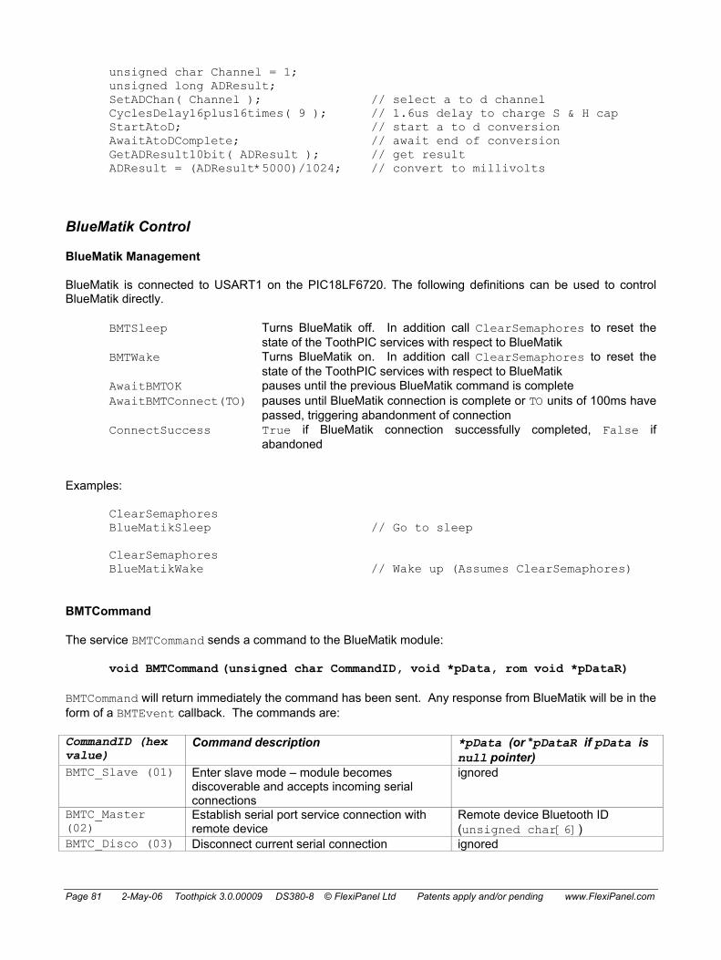
Page 81 2-May-06 Toothpick 3.0.00009 DS380-8 © FlexiPanel Ltd Patents apply and/or pending www.FlexiPanel.com
unsigned char Channel = 1; unsigned long ADResult; SetADChan( Channel ); // select a to d channel CyclesDelay16plus16times( 9 ); // 1.6us delay to charge S & H cap StartAtoD; // start a to d conversion AwaitAtoDComplete; // await end of conversion GetADResult10bit( ADResult ); // get result ADResult = (ADResult*5000)/1024; // convert to millivolts
BlueMatik Control
BlueMatik Management
BlueMatik is connected to USART1 on the PIC18LF6720. The following definitions can be used to control BlueMatik directly.
BMTSleep Turns BlueMatik off. In addition call ClearSemaphores to reset the state of the ToothPIC services with respect to BlueMatik
BMTWake Turns BlueMatik on. In addition call ClearSemaphores to reset the state of the ToothPIC services with respect to BlueMatik
AwaitBMTOK pauses until the previous BlueMatik command is complete AwaitBMTConnect(TO) pauses until BlueMatik connection is complete or TO units of 100ms have
passed, triggering abandonment of connection ConnectSuccess True if BlueMatik connection successfully completed, False if
abandoned
Examples:
ClearSemaphores BlueMatikSleep // Go to sleep ClearSemaphores BlueMatikWake // Wake up (Assumes ClearSemaphores)
BMTCommand
The service BMTCommand sends a command to the BlueMatik module:
void BMTCommand (unsigned char CommandID, void *pData, rom void *pDataR)
BMTCommand will return immediately the command has been sent. Any response from BlueMatik will be in the form of a BMTEvent callback. The commands are:
CommandID (hex value)
Command description *pData (or *pDataR if pData is null pointer)
BMTC_Slave (01) Enter slave mode – module becomes discoverable and accepts incoming serial connections
ignored
BMTC_Master (02)
Establish serial port service connection with remote device
Remote device Bluetooth ID (unsigned char[6])
BMTC_Disco (03) Disconnect current serial connection ignored

Page 82 2-May-06 Toothpick 3.0.00009 DS380-8 © FlexiPanel Ltd Patents apply and/or pending www.FlexiPanel.com
CommandID (hex value)
Command description *pData (or *pDataR if pData is null pointer)
BMTC_Inquire (04)
Search for other Bluetooth devices. Each device found generates a BMTE_Found event. Finally a BMTE_OK event generated.
inquiry duration in seconds as ASCII hexadecimal (zero terminated char[]), range 02 to 3C
BMTC_Security (05)
Sets security level to none (Sec_None), authentication (Sec_Auth) or authentication and encryption (Sec_AuthEncr)
security level as ASCII digit (zero terminated char[]) – see examples below
BMTC_Hold (0A) Enter hold mode. ignored BMTC_Sniff (08) Enter sniff mode. ignored BMTC_SniffX (09)
Exit sniff mode. ignored
BMTC_Signal (07)
Enquire link signal strength. ignored
BMTC_LinkQ (06) Enquire link quality. ignored BMTC_Cancel (0B)
Cancel the current BMTC_Slave, BMTC_Master or BMTC_Inquire command.
ignored
BMTC_Reset (0C) Reset BlueMatik. ignored BMTC_WFP (0D) Enter Wireless Field Programming mode. ignored BMTC_General (FF)
Send arbitrary command to BlueMatik as described in BlueMatik documentation.
ASCII command (zero terminated char[])
Examples:
BMTCommand( BMTC_Slave, 0, 0 ); // Enter slave mode AwaitBMTConnect( 0 ); // No timeout
unsigned char pBTAddr[] = { 0x01, 0x23, 0x45, 0x67, 0x89, 0xAB };
BMTCommand( BMTC_Master, (void *) pBTAddr, 0 ); // Connect to device AwaitBMTConnect( 50 ); // 5 sec timeout
if (!ConnectSuccess) {...}; // Test connection timeout BMTCommand( BMTC_Disco, 0, 0 ); // Disconnect AwaitBMTOK;
BMTCommand( BMTC_Sniff, 0, 0 ); // Enter Sniff mode AwaitBMTOK;
BMTCommand( BMTC_LinkQ, 0, 0 ); // Enquire link quality AwaitBMTOK; // Creates BMTE_LinkQ event
// set device class to camera rom static unsigned short long CamDevClass =
Dev_Imaging | ImDev_Display | ImDev_Camera | Svc_Capture; BMTCommand( BMTC_DevClass, 0, &CamDevClass );
AwaitBMTOK;
BMTCommand( BMTC_Inquire, 0, (rom void *)"A" ); // 10 second inquiry AwaitBMTOK;
BMTCommand( BMTC_Security, 0, Sec_AuthEncr ); // Authentication and AwaitBMTOK; // encryption (default)
// Set hold parameters (max, min, hex units of 0.625ms) BMTCommand( BMTC_General, 0, (rom void *)"AT+BSHP=200,80\r" );

Page 83 2-May-06 Toothpick 3.0.00009 DS380-8 © FlexiPanel Ltd Patents apply and/or pending www.FlexiPanel.com
AwaitBMTOK;
Notes:
BMTC_Inquire: Inquiry time is a tradeoff between speed and finding all devices. Searching for other devices using the BMTC_Inquire command will not necessarily find all available devices if the inquiry time is too short.
Bluetooth ID: The Bluetooth ID structure unsigned char[6] contains the non-significant address part (2 bytes, MSB first), followed by the upper address part (1 byte), followed by the lower address part (3 bytes, MSB first). Big-endian format (i.e. MSB first) is used in a departure from the C18 standard so that the array linearly matches the 01:23:45:67:89:AB form of Bluetooth address notation.
BMTC_Slave: In slave mode, BlueMatik becomes discoverable and it waits for a remote device to connect to it. When a master connects, a BMTE_Connect event occurs and the ToothPIC public data pRemoteBTAddr will contain the Bluetooth address of the master. If the master disconnects, a BMTE_Disco event is generated, the contents of pRemoteBTAddr will be cleared and BlueMatik the exits slave mode. To stay in slave mode and await another connection from a remote device, it is necessary to re-enter slave mode. You will need to use a semaphore to do this. See the Reset State
The following macros are defined to help you determine what caused the last reset. If none are true, the last reset was a hardware reset applied to the NMCLR pin.
ResetOrWakeEventWasPowerOn
ResetOrWakeEventWasStackOverflow
ResetOrWakeEventWasStackUnderflow
ResetOrWakeEventWasSoftwareReset
ResetOrWakeEventWasInterrtuptOrNMCLRDuringSleep
ResetOrWakeEventWasWDTReset
ResetOrWakeEventWasWDTWakeup
ResetOrWakeEventWasBrownOut Semaphores section for this exact example. Don’t send any data to BlueMatik until you get confirmation that the connection was successful using AwaitBMTConnect and ConnectSuccess.
ToothPIC also uses the term ‘slave mode’ in a different sense, where theToothPIC module is controlled by a host processor which via a conventional TTL serial connection. The firmware solution always referred to by its full name, ‘ToothPIC Slave’.
BMTC_Master: In master mode, BlueMatik actively attempts to connect to the remote device specified by the remote device ID. When connection is complete, a BMTE_Connect event occurs and the ToothPIC public data pRemoteBTAddr will contain the Bluetooth address of the remote device. Then when master or slave disconnects, a BMTE_Disco event is generated, the contents of pRemoteBTAddr will be cleared and BlueMatik then exits master mode. Don’t send any data to BlueMatik until you get confirmation that the connection was successful using AwaitBMTConnect and ConnectSuccess.
BMTC_Hold, BMTC_HoldX, BMTC_Sniff, BMTC_SniffX: The BlueMatik module supports two power saving modes, Hold and Sniff, as described in the section Power Saving. They apply only when a connection exists. To change from the default Hold and Sniff settings, consult the BlueMatik documentation and set the required values using the BMTC_General command.
BMTC_Signal, BMTC_LinkQ: The BMTC_Signal and BMTC_LinkQ commands give an idea of the signal strength and quality. The return values via the BMTE_Signal and BMTE_LinkQ BlueMatik events. The BMTE_Signal return value indicates the signal strength as follows:
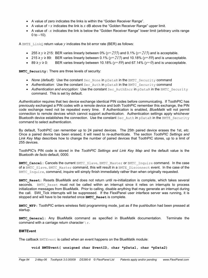
Page 84 2-May-06 Toothpick 3.0.00009 DS380-8 © FlexiPanel Ltd Patents apply and/or pending www.FlexiPanel.com
• A value of zero indicates the links is within the “Golden Receiver Range”. • A value of +x indicates the link is x dB above the “Golden Receiver Range” upper limit. • A value of –x indicates the link is below the “Golden Receiver Range” lower limit (arbitrary units range
0 to –10).
A BMTE_LinkQ return value y indicates the bit error rate (BER) as follows:
• 255 ≥ y ≥ 215: BER varies linearly between 0% (y=255) and 0.1% (y=215) and is acceptable. • 215 ≥ y ≥ 89: BER varies linearly between 0.1% (y=215) and 10.18% (y=89) and is unacceptable. • 89 ≥ y ≥ 0: BER varies linearly between 10.18% (y=89) and 67.14% (y=0) and is unacceptable.
BMTC_Security: There are three levels of security:
• None (default): Use the constant Sec_None in pDataR in the BMTC_Security command • Authentication: Use the constant Sec_Auth in pDataR in the BMTC_Security command • Authentication and encryption: Use the constant Sec_AuthEncr in pDataR in the BMTC_Security
command. This is set by default. Authentication requires that two device exchange identical PIN codes before communicating. If ToothPIC has previously exchanged a PIN codes with a remote device and both ToothPIC remember this exchange, the PIN code exchange need not be repeated every time. If Authentication is enabled, BlueMatik will not permit connection to remote devices which cannot support authentication. Authentication settings apply whichever Bluetooth device establishes the connection. Use the constant Sec_Auth in pDataR in the BMTE_Security command to select authentication.
By default, ToothPIC can remember up to 24 paired devices. The 25th paired device erases the 1st, etc. Once a paired device has been erased, it will need to re-authenticate. The section ToothPIC Settings and Link Key Map describes how to change the number of paired devices that ToothPIC stores, up to a limit of 255 devices.
ToothPIC's PIN code is stored in the ToothPIC Settings and Link Key Map and the default value is the Bluetooth de facto default, 0000.
BMTC_Cancel: Cancels the current BMTC_Slave, BMTC_Master or BMTC_Inquire command. In the case of a BMTC_Slave, BMTC_Master command, this will result in a BMTE_Disconnect event. In the case of the BMTC_Inquire, command, inquire will simply finish immediately rather than when originally requested.
BMTC_Reset: Resets BlueMatik and does not return until re-initialization is complete, which takes several seconds. BMTC_Reset must not be called within an interrupt since it relies on interrupts to process initialization messages from BlueMatik. Prior to calling, disable anything that may generate an interrupt during the call. SWI_Tick interrupts will be suppressed. If the FlexiPanel user interface server was running, it is stopped and will have to be restarted once BMTC_Reset is complete.
BMTC_WFP: ToothPIC enters wireless field programming mode, just as if the pushbutton had been pressed at startup.
BMTC_General: Any BlueMatik command as specified in BlueMatik documentation. Terminate the command with a carriage return character \r.
BMTEvent
The callback BMTEvent is called when an event happens on the BlueMatik module:
void BMTEvent( unsigned char EventID, char *pData1, char *pData2)

Page 85 2-May-06 Toothpick 3.0.00009 DS380-8 © FlexiPanel Ltd Patents apply and/or pending www.FlexiPanel.com
EventID identifies the event that happens. pData1 and pData2 may contain related information depending on the nature of the event:
EventID (hex value)
Event description *pData1 *pData2
BMTE_OK (00) Command completed OK
Not used Not used
BMTE_Error (01) Error message Error code (unsigned char) Not used BMTE_Warning (02)
BlueMatik warning message
Warning code (unsigned char)
Not used
BMTE_Connect (03)
Connection established Remote device Bluetooth ID (unsigned char[6])
Not used
BMTE_Disco (04) Connection terminated Not used Not used BMTE_Found (05) Device found during
inquiry. One event per device found.
Remote device’s Bluetooth ID (unsigned char[6])
Remote device’s name (zero terminated char[])
BMTE_Paired (06) New remote device successfully paired and added to pair list
Remote device’s Bluetooth ID (unsigned char[6])
Not used
BMTE_LinkQ (07) Link quality result Signal strength 0 to 255 (unsigned char)
Not used
BMTE_Signal (08) Signal strength result Signal strength –128 to 127 (char)
Not used
BMTE_LoPower (09)
Low power mode changed
Low power mode 0 to 2 (char) Low power mode interval (int16)
BMTE_Modem (0A) Modem status message from remote device
Modem status 0x00 to 0x1F (unsigned char)
Break signal 0x00 to 0xFF (unsigned char)
BMTE_HostProgram (0B)
WFP host program message received
Not used Not used
BMTE_General (FF)
Other response, e.g. from BMTE_General command
Response text (zero terminated char[])
Not used
Example:
void BMTEvent( unsigned char EventID, void *pData1, void *pData2 ) { // error or warning if ( EventID==BMTE_Error || ( EventID==BMTE_Error) #ifdef RELEASE_VERSION
Reset(); // unanticipated error - reset #else
Breakpoint( *((unsigned char*)pData1) ); // flash error number #endif // store link quality in uch if ( EventID==BMTE_LinkQ ) uch = *(unsigned char *) pData1; }
Notes:
BMTEvent may be called at any time, so care should be taken if modifying static values other than semaphores which are also used by your main code.

Page 86 2-May-06 Toothpick 3.0.00009 DS380-8 © FlexiPanel Ltd Patents apply and/or pending www.FlexiPanel.com
For forward compatibility, ignore any undocumented BMTE_ events rather than generating an error. This allows us to add new events in future without upsetting existing firmware.
BMTE_Disco: The BlueMatik transmit buffer is reset if a disconnect message is received.
BMTE_Modem: If the remote device sends a modem status message, a BMTE_Modem event is generated. The value of *pData1 is a bitwise-OR combination of the following:
Bitwise-OR value Meaning 0x01 RTC (Ready to communicate) 0x02 RTR (Ready to receive) 0x04 IC (Incoming call) 0x08 DV (Data valid) 0x10 FC (Flow control)
The value of *pData2 is a bitwise-OR combination of the following:
Bitwise-OR value Meaning 0x40 Remaining *pData2 fields are valid 0x0F Length of break signal in units of 200ms
Note that the extent to which remote devices support modem status messages may vary. The break signal is optional.
BMTE_HostProgram: Reserved for FlexiPanel Ltd use.
BMTE_General: Any other response from BlueMatik, usually as a result of a BMTC_General command.
BMTE_Warning and BMTE_Error do not trigger the ErrorStatus callback. However, a BMTE_OK event is issued after the BMTE_Warning and BMTE_Error event and also the ProcessingATCommand is cleared so that AwaitBMTOK does not block. This way execution can continue if possible.
The error and warning error codes are described in detail the BlueMatik documentation, but briefly, the most likely are:
Error code (hex) (decimal) Error description 0F 15 General error – see note below 10 16 Connection attempt while module not idle 11 17 Operation can’t be performed while active connection exists 12 18 Inquiry attempt while module not idle 15 21 Command unexpected or out of context 17 23 Command requires active serial connection 18 24 Operation cannot be cancelled – see note below 19 25 BlueMatik Link Database Error 1C 28 Flash memory too fragmented – perform BlueMatik reset
Warning code (hex) (decimal) Warning description 80 128 Sniff mode not enabled on BlueMatik 81 129 Hold mode not enabled on BlueMatik 82 130 No low power modes enabled on BlueMatik 83 131 Remote device does not support sniff mode 84 132 Remote device does not support hold mode 85 133 No low power modes supported on remote device 86 134 Low power mode has not changed

Page 87 2-May-06 Toothpick 3.0.00009 DS380-8 © FlexiPanel Ltd Patents apply and/or pending www.FlexiPanel.com
Error code 0x0F (general error), is generated when BlueMatik responds with an error message but specifies no error number. If custom commands are being sent, it probably means that a command was not understood. Error code 0x0F can also be generated (i) on disconnection if both sides attempt to initiate the disconnection, or (ii) if data is sent before a connection was established or after it was closed (since BlueMatik will try to interpret this data as a command). Note in particular that if a remote device disconnects while ToothPIC is trying to send it data, a general error be generated. The correct response to this is to perform a BMTC_Reset command to return BlueMatik to a known state. See any of the firmware solutions for an example of how this is done.
BlueMatik Serial Communications
NOTE: As of ToothPIC 3.0.00005, the transmit buffer is not used and BMTTransmit will not return until the data has been transmitted.
BlueMatik serial communications services allow you to send data to and receive data from Bluetooth devices that BlueMatik is connected to. These services are not compatible with the FlexiPanel User Interface services – you can use one or the other, but not both at the same time.
ToothPIC implements buffered I/O with fixed buffers of 256 bytes.
• RAM locations 0x800 to 0x8FF are reserved for the transmit buffer • RAM locations 0x900 to 0x9FF are reserved for the receive buffer
ToothPIC employs the buffers as circular buffers and the following variables and macros are defined in ToothPIC.h:
Definition Function BMTRxStart Any data remaining in the buffer starts at pRxBuff[BMTRxStart]. BMTRxEnd Any data remaining in the buffer ends at pRxBuff[BMTRxEnd], having
wrapped around from the end to the beginning if necessary. BMTRxNChar Number of characters in the receive buffer BMTRxEmpty True if the receive buffer is empty ResetBMTRx Resets state of receive buffer (all data will be lost) BMTTxStart Any data remaining in the buffer starts at pTxBuff[BMTTxStart]. BMTTxEnd Any data remaining in the buffer ends at pTxBuff[BMTTxEnd], having
wrapped around from the end to the beginning if necessary. BMTTxNChar Number of characters remaining in the transmit buffer BMTTxSpace Number of spare bytes in the transmit buffer (max 255) BMTTxEmpty True if the transmit buffer is empty ResetBMTTx Resets state of transmit buffer (all data will be lost)
To read and write data, the following macros and services are provided:
BMTTransmit
NOTE: As of ToothPIC 3.0.00005, BMTTransmit does not use the transmit buffer and it will not return until the data has been transmitted.
The BMTTransmit service transmits serial data.
Bool BMTTransmit( unsigned char *pTxDataR, unsigned char *pTxData, unsigned char nBytes, unsigned char msTimeOut )

Page 88 2-May-06 Toothpick 3.0.00009 DS380-8 © FlexiPanel Ltd Patents apply and/or pending www.FlexiPanel.com
If there is enough available space, nBytes of data is placed in the buffer and the function returns immediately with the value True. If pTxDataR is non-zero, the data is sourced from that ROM address; otherwise it is sourced from the RAM address pTxData. If the transmit buffer does not contain sufficient space for nBytes, it will wait for up to msTimeOut milliseconds for sufficient space. If at the end of that period there is still insufficient space, BMTTransmit will return with the value False, without adding any data to the transmit buffer; in addition, if msTimeOut was an odd number, a ERR_TXTIMEOUT error status event will be generated before returning. If msTimeOut is zero, BMTTransmit will not return until sufficient space is available in the buffer.
The BlueMatik transmit buffer is reset if the remote device disconnects.
BMTTxAdvance, BMTTxAdvanceCh
BMTTxAdvance( unsigned char i ) BMTTxAdvanceCh
The BMTAdvance macro advances the transmit buffer end pointer BMTTxEnd by i bytes. The BMTAdvanceCh macro advances the transmit buffer end pointer BMTTxEnd by 1 byte. Transmission will take place as soon as possible. They are high-speed macros and no buffer overrun checks are made. Use the BMTTxWaitBytes macro or BMTRxEmpty value to wait until there is room for more data in the transmit buffer. i must be of type unsigned char – this is a macro and no type casting is done.
The BlueMatik transmit buffer is reset if the remote device disconnects.
As of ToothPIC 3.0.00005, BMTTxAdvance and BMTTxAdvanceCh have not been fully implemented and the BMTTransmit macro should be used instead.
BMTTxLoc, BMTTxCh
unsigned char * BMTTxLoc( unsigned char i ) unsigned char * BMTTxCh
The BMTTxLoc(i) macro is a pointer to the memory location of the ith character in the transmit buffer after the end point BMTTxEnd, accounting for the fact that the buffer is circular. The BMTTxCh macro is a pointer to the memory location of the transmit buffer end point BMTTxEnd. i must be of type unsigned char – this is a macro and no type casting is done. i is zero-based, so BMTTxLoc(0) so is the next vacant position in the transmit buffer.
BMTTxLoc / BMTTxCh and BMTTdvance / BMTTxAdvanceCh provide a memory- and time-efficient way of writing data into the buffer for transmission. They are high-speed macros and no buffer overrun checks are made. Use the BMTTxWaitBytes macro value to wait until there is room for more data in the transmit buffer.
Examples:
BMTTxWaitBytes(1); // Wait for space *BMTTxCh = 'A'; // Put character in buffer BMTTxAdvanceCh; // Transmit char i; BMTTxWaitBytes(26); for ( i=0; i<26; i++ )
*BMTTxLoc(i) = 'A' + i; // Whole alphabet BMTTxAdvance(26); As of ToothPIC 3.0.00005, BMTTxLoc and BMTTxCh have not been fully implemented and the BMTTransmit macro should be used instead.

Page 89 2-May-06 Toothpick 3.0.00009 DS380-8 © FlexiPanel Ltd Patents apply and/or pending www.FlexiPanel.com
BMTTxWaitBytes
void BMTTxWaitBytes( unsigned char i ) The BMTTxWaitBytes(i) macro waits until there is space in the transmit buffer to add i characters. It can be called before BMTTxAdvance to avoid buffer overrun. i must be of type unsigned char – this is a macro and no type casting is done.
As of ToothPIC 3.0.00005, BMTTxWaitBytes has not been fully implemented and the BMTTransmit macro only should be used.
BMTReceive
Bool BMTReceive( unsigned char *pRxData, unsigned char nBytes, unsigned char msTimeOut )
BMTReceive service takes nBytes of serial data from the receive buffer and places them in pRxData. If it does so successfully, the return value is True. If the receive buffer does not contain sufficient data nBytes, it will wait for up to msTimeOut milliseconds for sufficient data. If at the end of that period there is still insufficient data, BMTReceive will return with the value False, leaving the receive buffer and pRxData untouched; in addition, if msTimeOut was an odd number, a ERR_RXTIMEOUT error status event will be generated before returning. If msTimeOut is zero, BMTReceive will not return until sufficient data is in the buffer.
BMTRxAdvance, BMTRxAdvanceCh
BMTRxAdvance( unsigned char i ) BMTRxAdvanceCh
The BMTAdvance macro advances the receive buffer start pointer BMTRxStart by i bytes. The BMTAdvanceCh macro advances the receive buffer start pointer BMTRxStart by 1 byte. They are high-speed macros and no buffer underrun checks are made. Use the BMTRxWaitBytes macro or BMTRxEmpty value to test whether there is any data to receive. i must be of type unsigned char – this is a macro and no type casting is done.
Examples: if (!BMTRxEmpty) { char ch; ch = *BMTRxCh; // Fetch a character BMTRxAdvanceCh; }
BMTRxLoc, BMTRxLoc
unsigned char * BMTRxLoc( unsigned char i ) The BMTRxLoc(i) macros is a pointer to the memory location of the ith character in the receive buffer after the start point BMTRxStart, accounting for the fact that the buffer is circular. i must be of type unsigned char – this is a macro and no type casting is done.
BMTRxLoc / BMTRxCh and BMTRxAdvance / BMTRxAdvanceCh provide a memory- and time-efficient way of reading and discarding data in the buffer. They are high-speed macros and no buffer underrun checks are made. Use the BMTRxWaitBytes macro or BMTRxEmpty value to test whether there is any data to receive. i is zero-based, so BMTRxLoc(0) so is the next character to be read from the receive buffer.

Page 90 2-May-06 Toothpick 3.0.00009 DS380-8 © FlexiPanel Ltd Patents apply and/or pending www.FlexiPanel.com
BMTRxWaitBytes
void BMTRxWaitBytes( unsigned char i ) The BMTRxWaitBytes(i) macro waits until there are i characters in the receive buffer. It can be called before BMTRxAdvance to avoid buffer underrun. . i must be of type unsigned char – this is a macro and no type casting is done.
Bluetooth Device Classes
The 3-byte Bluetooth device class, specified in the ToothPIC Settings and Link Key Map as the variable DeviceClass, determines what the module claims to be when other Bluetooth devices ask it. It affects the icon that appears on other Bluetooth devices and may affect the device discovery function. In particular some mobile phones only look for certain sub classes, e.g. headsets.
The device class consists of three elements: the services available, the major device class and the minor device class. BlueMatik can be programmed to claim to be capable of any number of services, however exactly one Major Class must be specified. The minor device class is an optional addition, defining a subset of the major device class.
Services and Major Device Class
The first two bytes of the device class contain the services information and the major device class. They are calculated by bitwise-ORing together as many services that are required and the one Major Device Class required. (ToothPIC.h provides definitions for these values.)
Byte A Byte B Description Data Type 0x00 0x20 Limited discovery mode (default) 0x01 0x00 Positioning 0x02 0x00 Network (default) 0x04 0x00 Rendering 0x08 0x00 Capturing 0x10 0x00 Object transfer (default) 0x20 0x00 Audio 0x40 0x00 Telephony (default) 0x80 0x00 Information
Services
0x00 0x01 Computer 0x00 0x02 Phone (default) 0x00 0x03 LAN 0x00 0x04 AV 0x00 0x05 Peripheral 0x00 0x06 Imaging 0x00 0x1F Uncategorized 0x00 0x00 Miscellaneous Device Class
Device Major Class
Example
If BlueMatik is required to claim network and object transfer and information services, and appear as a peripheral then the device configuration bytes are:

Page 91 2-May-06 Toothpick 3.0.00009 DS380-8 © FlexiPanel Ltd Patents apply and/or pending www.FlexiPanel.com
Byte A Byte B
0x02 (0000 0010) 0x00 (0000 0000) Network Services
0x10 (0001 0000) 0x00 (0000 0000) Object transfer Services
0x80 (1000 0000) 0x00 (0000 0000) Information Services
0x00 (0000 0000) 0x05 (0000 0101) Peripheral Device Major Class
Resulting bytes (bitwise OR together the above)
Byte A Byte B
0x92 1001 0010 0x05 0000 0101
Minor device class
The last byte defines the minor device class. Its interpretation depends on the major device class specified as follows. (ToothPIC.h provides definitions for these values.)
Byte C Computer Major Class
Phone Major Class
LAN Major Class
AV Major Class
0x00 Other Other LAN 0% utilized Other 0x04 Desktop Cellphone (default) Wearable headset 0x08 Server Cordless phone Hands free device 0x0C Laptop Smartphone 0x10 Handheld Gateway / modem Microphone 0x14 Palm-sized ISDN Loudspeaker 0x18 Wearable Headphones 0x1C Walkman 0x20 LAN 1-17% utilized Car audio 0x24 Set top box 0x28 Hi-Fi 0x2C VCR 0x30 Video camera 0x34 Camcorder 0x38 Monitor 0x3C Monitor with audio 0x40 LAN 17-33% utilized Conferencing device 0x48 Toy 0x60 LAN 33-50% utilized 0x80 LAN 50-67% utilized 0xA0 LAN 67-83% utilized 0xC0 LAN 83-99% utilized 0xE0 LAN 100% utilized
Byte C Peripheral Device Class Bitwise-OR together one † value and
one ‡ value
Imaging Device Class Bitwise-OR together as many values as apply
Uncategorized / Miscellaneous Device
Class 0x00 No keyboard or pointing device † Uncategorized /
Miscellaneous 0x00 Other ‡ 0x04 Joystick 0x08 Gamepad ‡ 0x0C Remote control ‡

Page 92 2-May-06 Toothpick 3.0.00009 DS380-8 © FlexiPanel Ltd Patents apply and/or pending www.FlexiPanel.com
0x10 Sensing device ‡ Display 0x14 Digitizer ‡ 0x18 Card reader‡ 0x1C 0x20 Camera 0x40 Keyboard but no pointing device † Scanner 0x80 Pointing device but no keyboard † Printer 0xC0 Keyboard and pointing device †
Callbacks
When events occur that ToothPIC wants to tell you about, it calls a callback function. Callbacks are functions which you must provide, even if you do nothing in them. The “Hello World” Firmware Solutions show the minimum your application needs to do in terms of callback functions.
Callbacks generally occur while ToothPIC is servicing a low-priority interrupt. Therefore your callback function can’t do anything which relies on interrupts being responded to. This includes functions such as AwaitBMTOK, which require interpretation of incoming serial data from BlueMatik. It does not include most BMTCommands and FxPCommands which transmit data only. (The exception is BMTReset, which cannot be called from within a callback.) If necessary, set a semaphore inside the callback then return from the callback function. From inside your main code, inspect the semaphore value frequently and respond appropriately when it is set. (See the Semaphores section for an example.)
The callback functions are ErrorStatus, BMTEvent and FxPEvent.
ErrorStatus
ErrorStatus( unsigned char ErrNum )
Called if an error happens. Unless otherwise documented, errors are viewed as fatal and if you return from ErrorStatus() results may be unpredictable, particularly if ErrorStatus or any of the functions it calls use static variables. ErrNum indicates the exact nature of the error and will be one of the following:
Name Value Explanation ERR_BMTATBUFFOVERRUN 0x01 AT response received before the previous one was
processed. ERR_BMTFRAME 0x02 Framing error on BlueMatik UART. Most likely the
clock speed is wrong or a BlueMatik with incorrect default baud rate has been installed.
ERR_BMTOVERRUN 0x03 BlueMatik input overrun – previous received character was not added to buffer by the time the next character was received.
ERR_NOBLUEMATIK 0x04 BlueMatik not initialized yet. May not be installed. ERR_WAITINGPREV 0x05 Still awaiting completion of previous command ERR_BMTBUFFOVERRUN 0x06 BlueMatik receive buffer overrun – no room left in
receive buffer ERR_FLEXIPANELSERVICE 0x07 Operation not possible because FlexiPanel user
interface service is in operation ERR_NOFLEXIPANELSERVICE 0x08
Operation not possible because FlexiPanel user interface service is not in operation
ERR_RXTIMEOUT 0x09 BMTReceive timed out and the timeout value was odd (i.e. not even). If you return from ErrorStatus(), results BMTReceive will return with return value False.
ERR_TXTIMEOUT 0x0A BMTTransmit timed out and the timeout value was odd (i.e. not even). If you return from

Page 93 2-May-06 Toothpick 3.0.00009 DS380-8 © FlexiPanel Ltd Patents apply and/or pending www.FlexiPanel.com
ErrorStatus(), results BMTReceive will return with return value False.
ERR_MEMORYFAILURE 0x0B SetBytes attempted to write verifiably to nonvolatile memory 100 times and failed.
ERR_ARGUMENTINERROR 0x0C An argument passed to ToothPIC function does not make sense.
BMTEvent
BMTEvent(unsigned char *ResponseID, unsigned char *BTAddr, char *szName)
Called when an event happens on the BlueMatik module. Detailed in the BlueMatik section.
FxPEvent
void FxPEvent( unsigned char EventID, char *pData)
Called when a FlexiPanel user interface event happens. Detailed in the FlexiPanel Server section.
Comparators
The PIC18LF6720’s Dual Analog Comparators are available for developer use on certain ANx pins. The following macros are provided in ToothPIC.h:
Macro Effect CmpsOff Comparators not configured CmpsBuffer Digital output AN7 equals value of digital input AN11,
Digital output AN6 equals value of digital input AN9 (also AN10 outputs 2.5V)
CmpsInvert AN7 outputs the digital inverse of input AN11, AN6 outputs the digital inverse of input AN9 (also AN10 outputs 2.5V)
SetCmpsIntOnChange (iPriority)
PIR2bits.CMIF generated if AN11 or AN9 changes state (must be cleared in software). Set iPriority to 1 for high priority, 0 for low priority.
Configuration Settings
ToothPIC assumes the following configuration settings on the PIC18LF6720:
• HS oscillator configuration • Watchdog timer off • Watchdog timer postscaler 1:128 • Power-up timer on • Oscillator switch enabled • CCP2 Mux RE7 • Table Write Protect 00200-03FFF enabled • Table Write Protect 04000-08FFF enabled • Table Write Protect 08000-0BFFF enabled • Table Write Protect 00000-001FF enabled

Page 94 2-May-06 Toothpick 3.0.00009 DS380-8 © FlexiPanel Ltd Patents apply and/or pending www.FlexiPanel.com
Count, Capture and Compare
The PIC18LF6720’s Capture and Compare I/O are available for developer use on the CCP pins. Developers will need to consult PIC18LF6720 documentation to use this feature.
The PIC18LF6720’s Timer0 Counter is also available for developer use. Developers will need to consult PIC18LF6720 documentation to use this feature.
Copy Protection
For product releases, you are advised to set the copy protect bits so that it is difficult to copy your firmware.
FlexiPanel Ltd provides the ToothPIC Services library exclusively for use with ToothPIC products that it supplies. It will only work with Bluetooth components supplied by us. Any attempt to reverse engineer the library to make it compatible with other Bluetooth components is illegal. To protect against reverse engineering, some of the copy protection features in the ToothPIC only trigger under certain conditions. If the ToothPIC Services library is used with Bluetooth components that are not supplied by us, it may work initially but ‘self destruct’ at a later date. Use of such features minimizes costs to our legitimate customers.
Date-Time Values
The real time clock, date time controls and the matrix control (date-time X axis style) use the 8-byte DateTimeU structure defined in ToothPIC.h. It consists of the following fields:
Field name Datatype Contains Range sec byte Second 0 – 59 min byte Minute 0 – 59 hour byte Hour 0 – 23 date byte Date 1 – 31 dow byte Day of
week 0 – 6 Sunday to Saturday respectively 7 = Unknown
month byte Month 1 – 12 year uint16 Year 0 – 65535
Depending on the interpretation of the structure, not all date-time fields need be valid. For example, a date-time field may represent a birthday, in which case only date and month would be valid; an alarm time, in which hour and minute are valid, etc.
A CalcDayOfWeek function is provided in ToothPIC.h to calculate the day of week for any given date. (See Utility Functions section.)
Digital I/O (Bitwise)
All pins except Vin, Vdd, Vss and NMCLR may be configured as single bit digital I/O provided they are not used for another function.
Pin Direction setting variable Value storing variable AN0 DirAN0 AN0Pin AN1 DirAN1 AN1Pin AN2 DirAN2 AN2Pin AN3 DirAN3 AN3Pin AN4 DirAN4 AN4Pin AN5 DirAN5 AN5Pin AN6 DirAN6 AN6Pin AN7 DirAN7 AN7Pin AN8 DirAN8 AN8Pin AN9 DirAN9 AN9Pin

Page 95 2-May-06 Toothpick 3.0.00009 DS380-8 © FlexiPanel Ltd Patents apply and/or pending www.FlexiPanel.com
Pin Direction setting variable Value storing variable AN10 DirAN10 AN10Pin AN11 DirAN11 AN11Pin CCP1 DirCCP1 CCP1Pin CCP2 DirCCP2 CCP2Pin CCP3 DirCCP3 CCP3Pin CCP4 DirCCP4 CCP4Pin CCP5 DirCCP5 CCP5Pin INT0 DirINT0 INT0Pin INT1 DirINT1 INT1Pin RxD DirRxD RxDPin SCL DirSCL SCLPin SDA DirSDA SDOPin SDO DirSDO SDAPin TxD DirTxD TxDPin
To set or read the I/O direction, set the direction setting variable as appropriate using the constants DirInput and DirOutput. For example:
DirRxD = DirInput; // RxD is a digital input
DirTxD = DirOutput; // TxD is a digital ouput
To retrieve an input or output value, or set an output value, use the value storing variable as appropriate, for example:
if ( RxDPin == 1 ) // if RxD is at logic 1
TxDPin = 0; // set TxD to logic 0
Digital I/O (Parallel)
Parallel I/O reads or sets multiple I/O bits in one instruction. The following can provide parallel I/O provided the pins are not used for another function. Only one each of PAx, PBx and PCx may be used at a time.
Name Bits Pins (MSB first) Direction setting function
Value setting function
Value getting variable
PA7 7 AN11 – AN5 DirPA7( char ) SetPA7( char ) GetPA7 PA6 6 AN11 – AN6 DirPA6( char ) SetPA6( char ) GetPA6 PA5 5 AN11 – AN7 DirPA5( char ) SetPA5( char ) GetPA5 PA4 4 AN11 – AN8 DirPA4( char ) SetPA4( char ) GetPA4 PA3 3 AN11 – AN9 DirPA3( char ) SetPA3( char ) GetPA3 PA2 2 AN11,AN10 DirPA2( char ) SetPA2( char ) GetPA2 PB5 5 AN4 – AN0 DirPB5( char ) SetPB5( char ) GetPB5 PB4 4 AN4 – AN1 DirPB4( char ) SetPB4( char ) GetPB4 PB3 3 AN4 – AN2 DirPB3( char ) SetPB3( char ) GetPB3 PB2 2 AN4,AN3 DirPB2( char ) SetPB2( char ) GetPB2 PC5 5 CCP5,CCP4,RxD,TxD,CCP3 DirPC5( char ) SetPC5( char ) GetPC5 PC4 4 CCP5,CCP4,RxD,TxD DirPC4( char ) SetPC4( char ) GetPC4 PC3 3 CCP5,CCP4,RxD DirPC3( char ) SetPC3( char ) GetPC3 PC2 2 CCP5,CCP4 DirPC2( char ) SetPC2( char ) GetPC2
To set or read the I/O direction, set the direction setting function as appropriate using the constants DirParInput and DirParOutput. For example:
DirPA7( DirParInput ); // Set up PA7 digital input

Page 96 2-May-06 Toothpick 3.0.00009 DS380-8 © FlexiPanel Ltd Patents apply and/or pending www.FlexiPanel.com
DirPC4( DirParOutput ); // Set up PC4 digital output
To retrieve an input or output value, use the value getting variable as appropriate, for example:
if ( GetPB3 == 0x03 ) // if AN1 is 0, AN2 is 1, AN3 is 1, // e.g. binary 011 = 0x03
To set an output value, use the value getting function as appropriate, for example:
SetPA4( 0x09 ); // set AN8 to 1, AN9 to 0, AN10 to 0, AN11 to 1 // e.g. binary 1001 = 0x09
FlexiPanel Server
Overview
The FlexiPanel server allows remote devices such as Windows PCs, handhelds and cell phones to display user interfaces (UIs) on its behalf. It uses the FlexiPanel Bluetooth Protocol to transmit the required UI to the remote device. The remote device needs to run the FlexiPanel Client software which is freely available from FlexiPanel Ltd. The Client software does not require customization, since the UI specifications are stored on the server, and transmitted to the client when it connects. The server is not concerned about the type of client which connects – it treats them equally.
The UI specification is compiled using FlexiPanel Designer software which is freely available from FlexiPanel Ltd. It is stored from memory location 0x010000 onwards. (The linker will fit the developer’s code around it.)
To set and retrieve control values, macros are defined in the header file generated by FlexiPanel Designer.
FxPCommand
The service FxPCommand sends a command to the FlexiPanel server:
void FxPCommand(unsigned char CommandID, unsigned short IDVal, void * iVal) FxPCommand will return immediately the command has been processed. Asynchronous responses from the FlexiPanel user interface server will be in the form of FxPEvent callbacks. The commands are:
CommandID (hex value) Command description IDVal pVal FxPC_Start (01) Starts FlexiPanel server ignored ignored FxPC_Finish (02) ignored ignored FxPC_SetDialog (03) Selects a new dialog to display Dialog index number
(high byte ignored) ignored
FxPC_Disco (04) Disconnects currently connected remote device
ignored ignored
FxPC_CtlUpdate (05) Refreshes the value of a control on the client
ID of updated control ignored
FxPC_PartUpdate (06) Refreshes the value of a single matrix row on the client
ID of updated control Row number (short cast to void *)
FxPC_SetProps (07) Sets control properties and color
ID of updated control New properties (unsigned long *)
FxPC_InitData (09) (Re-) initializes control data ignored ignored FxPC_MultiUpdate (0A) Prepares to send multiple
FxPC_CtlUpdate updates in a single message
Number of FxPC_CtlUpdate commands to follow
ignored
FxPC_MultiPartUpdate (0B)
Prepares to send multiple FxPC_PartUpdate updates in
Number of FxPC_PartUpdate
ignored

Page 97 2-May-06 Toothpick 3.0.00009 DS380-8 © FlexiPanel Ltd Patents apply and/or pending www.FlexiPanel.com
CommandID (hex value) Command description IDVal pVal a single message commands to follow
FxPC_MultiPropsUpdate (0C)
Prepares to send multiple FxPC_SetProps updates in a single message
Number of FxPC_SetProps commands to follow
ignored
Examples:
FxPCommand( FxPC_Start, 0, 0 ); // Start FlexiPanel service AwaitBMTOK( 0 ); // Service operating, no client
Notes:
ERR_TXTIMEOUT: If this error is generated a serious transmission failure occurred and ToothPIC has entered an unpredictable state. For robust performance, reset if this error is received while the FlexiPanel server is running.
Use with BMTCommand: No communication can be made using BlueMatik while the FlexiPanel server is running except via the FlexiPanel server. No other connection should be established or device inquiry made while the FlexiPanel server is operating. Name, security and encryption should be set up before the FlexiPanel server is started. Link quality and signal strength may be enquired at any time. Low power modes may be requested at any time (the FlexiPanel service does not invoke them itself).
FxPC_Start: Starts FlexiPanel service. Responds with BMTE_OK event when the server has started, with BMTE_Connect when any remote device connects and with FxPE_Connect when the remote device identifies itself as a FlexiPanel client.
FxPC_SetDialog: FlexiPanel Designer permits multiple dialogs to be defined for ToothPIC using the New Dialog control property. FxPC_SetDialog selects the dialog that is displayed. The dialog index numbers start at zero. For convenience, DlgID_ ID numbers are defined in the header file generated by FlexiPanel Designer. The new dialog will automatically be sent to the client if a client is connected. FxPC_SetDialog may be called prior to FxPC_Start. If not, FxPC_Start will default to the first dialog. Returns when request has been registered and updates the client in the next available software interrupt slot. No event is generated to confirm the result.
FxPC_CtlUpdate: Sends the new value of a modified control to the client. The contents should be modified beforehand using the macros defined in the header file generated by FlexiPanel Designer. If you have several controls which you wish to appear to update simultaneously, modify all values first and then send a FxPC_CtlUpdate for each control afterwards. If the change is simple, the client will be updated immediately. If complete retransmission of the dialog is required because a section or password changed, the client is updated in the next available software interrupt slot. No event is generated to confirm the result.
If FxPC_CtlUpdate is called for a section or password control, certain other controls may appear or disappear so the entire dialog will likely be resent automatically by the FlexiPanel server.
Most of the macros defined in FlexiPanel Designer for accessing the control values are self-evident and the worked examples sections provide examples of their use. The following example is for a list control:
// List5 control (05 - List) #define ID_List5_5 0x0005 // the ID of the control // Get_List5_5( pLong ) gets List5 value. pLong must be pointer to 4-byte signed integer // if the value could fit into a short or char, you could get fewer bytes #define Get_List5_5( pLong ) GetBytes( STR_RAM, 0x002C, pLong, sizeof(long) ) // plList5_5 is an unsigned long RAM pointer which may also be used to set or get the value #define plList5_5 ((unsigned long*)0x012C)

Page 98 2-May-06 Toothpick 3.0.00009 DS380-8 © FlexiPanel Ltd Patents apply and/or pending www.FlexiPanel.com
// Set_List5_5( pRLong, pLong ) sets List5 value. pRULong must be rom pointer to 4-byte signed integer // or pULong must be pointer to 4-byte signed integer, the other pointer must be zero #define Set_List5_5( pRLong, pULong ) SetBytes( STR_RAM, 0x002C, pRULong, pULong, sizeof(long) ) // SetUp_List5_5( pRLong, pLong ) sets List5 value and automatically updates client if connected #define SetUp_List5_5( pRLong, pLong ) { Set_List5_5( pRLong, pLong );
FxPCommand( FxPC_CtlUpdate, ID_List5_5, 0 ); } // NumItem_List5_5 is the number of items in the list #define NumItem_List5_5 3
The ID will always be specified. For most controls, a Get_ function is always provided to retrieve the data, a Set_ function to set the data value and a SetUp_ function to set the value and update the value on the client at the same time. If the data is directly accessible as a pointer, a pointer is also provided. (Bear in mind that you cannot set the value referenced by a ROM pointer – you need to use the Set_ macro.) Examples:
// increment list selection by Get_ and SetUp_ macros long lVal; Get_List5_5( &lVal ); lVal = lVal + 1; SetUp_List5_5( &lVal ); // increment list selection by pointer macros *plList5_5 = *plList5_5 + 1; FxPCommand( FxPC_CtlUpdate, ID_List5_5, 0 );
The Matrix control value is more complex and is composed of three parts: (i) the cell values, (ii) the row value (XY and Date-Time types only), (iii) the Matrix Row Counter. The Cell values are set using the Set_Cell macro, etc; the row value, if appropriate, is set using the Set_Row macro, etc.
The Matrix Row Counter indicates the number of rows of data which contain meaningful values and is accessed using the Set_RowCounter macro, etc. It is initialized to zero. When you add data to a matrix row, you must set the value of the Row Counter also. Do not set it to a new value until all the data in that row are valid. You can also append data to the matrix in a first-in first-out (FIFO) fashion. To do this, set the data in the row value indicated by the AppendRow_ macro. Then instead of modifying the Row Counter directly, execute the NextAppendRow_ macro to move the row pointer on to the next position. When the matrix is full, the Row Counter value becomes negative indicating to the client that all values are valid and offset in a circular buffer fashion. Examples:
// setting the values of a labels style control short Row, Col; char cVal; long lVal; for (Row = 0; Row < MaxRow_Matrix3_3; Row++) { for (Col = 0; Col < NumCol_Matrix3_3; Col++) { cVal = Row + Col * 10; Set_Matrix3_3_Cell( 0, &cVal, Row, Col ); } } lVal = MaxRow_Matrix3_3; Set_Matrix3_3_RowCounter( 0, &lVal ); // appending a value to a DateTime style control char cVal = 123; Set_Matrix4_4_Cell( 0, & cVal, AppendRow_Matrix4_4, 0 ); Set_Matrix4_4_Row( 0, &RealTimeClock, AppendRow_Matrix4_4 ); NextAppendRow_Matrix4_4; FxPCommand( FxPC_CtlUpdate, ID_Matrix4_4 );
FxPC_PartUpdate: Sends a single row of matrix data to the client. The row data should be modified beforehand using the macros defined in the header file generated by FlexiPanel Designer. Part updates are only possible from version 3 of the FlexiPanel Protocol. If the client device is version 2, a full update will automatically be sent instead. The following example shows FxPC_PartUpdate used for data logging to a matrix.
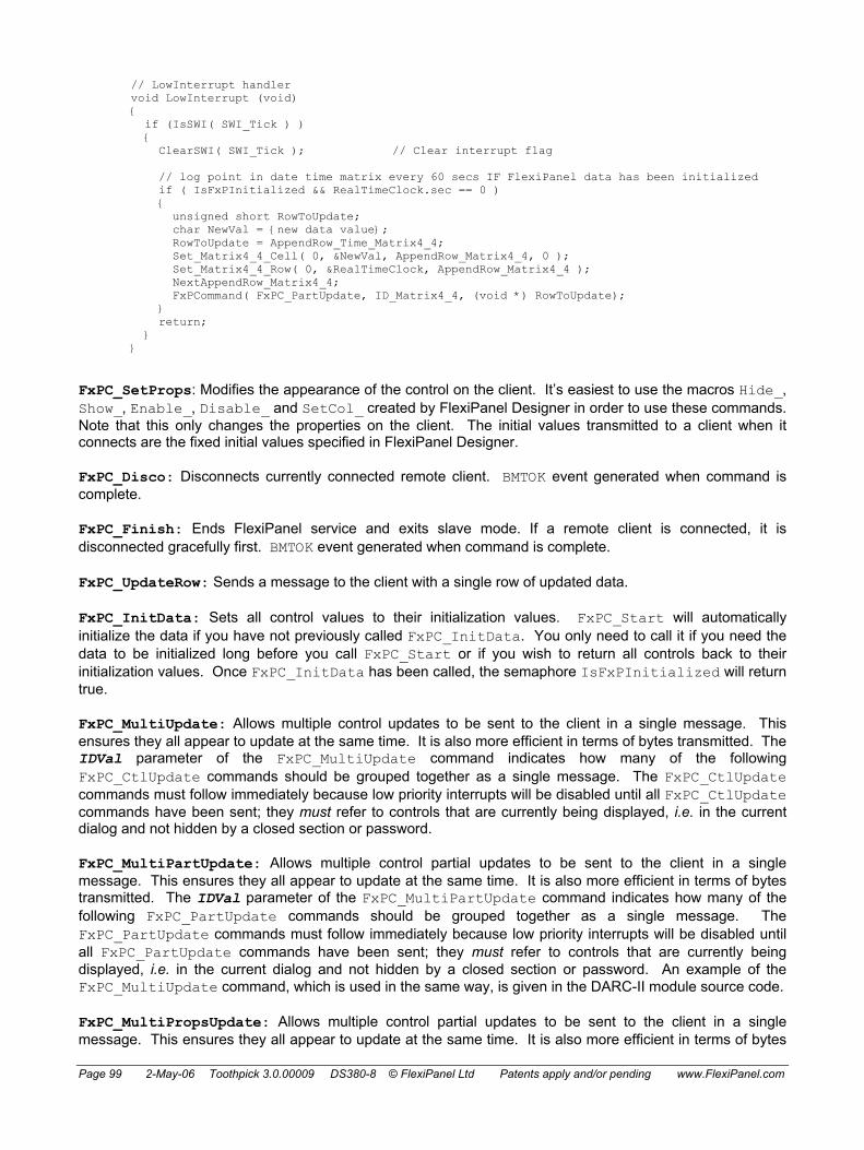
Page 99 2-May-06 Toothpick 3.0.00009 DS380-8 © FlexiPanel Ltd Patents apply and/or pending www.FlexiPanel.com
// LowInterrupt handler void LowInterrupt (void) {
if (IsSWI( SWI_Tick ) ) { ClearSWI( SWI_Tick ); // Clear interrupt flag // log point in date time matrix every 60 secs IF FlexiPanel data has been initialized if ( IsFxPInitialized && RealTimeClock.sec == 0 ) { unsigned short RowToUpdate;
char NewVal = {new data value}; RowToUpdate = AppendRow_Time_Matrix4_4;
Set_Matrix4_4_Cell( 0, &NewVal, AppendRow_Matrix4_4, 0 ); Set_Matrix4_4_Row( 0, &RealTimeClock, AppendRow_Matrix4_4 ); NextAppendRow_Matrix4_4; FxPCommand( FxPC_PartUpdate, ID_Matrix4_4, (void *) RowToUpdate); } return; }
}
FxPC_SetProps: Modifies the appearance of the control on the client. It’s easiest to use the macros Hide_, Show_, Enable_, Disable_ and SetCol_ created by FlexiPanel Designer in order to use these commands. Note that this only changes the properties on the client. The initial values transmitted to a client when it connects are the fixed initial values specified in FlexiPanel Designer.
FxPC_Disco: Disconnects currently connected remote client. BMTOK event generated when command is complete.
FxPC_Finish: Ends FlexiPanel service and exits slave mode. If a remote client is connected, it is disconnected gracefully first. BMTOK event generated when command is complete.
FxPC_UpdateRow: Sends a message to the client with a single row of updated data.
FxPC_InitData: Sets all control values to their initialization values. FxPC_Start will automatically initialize the data if you have not previously called FxPC_InitData. You only need to call it if you need the data to be initialized long before you call FxPC_Start or if you wish to return all controls back to their initialization values. Once FxPC_InitData has been called, the semaphore IsFxPInitialized will return true.
FxPC_MultiUpdate: Allows multiple control updates to be sent to the client in a single message. This ensures they all appear to update at the same time. It is also more efficient in terms of bytes transmitted. The IDVal parameter of the FxPC_MultiUpdate command indicates how many of the following FxPC_CtlUpdate commands should be grouped together as a single message. The FxPC_CtlUpdate commands must follow immediately because low priority interrupts will be disabled until all FxPC_CtlUpdate commands have been sent; they must refer to controls that are currently being displayed, i.e. in the current dialog and not hidden by a closed section or password.
FxPC_MultiPartUpdate: Allows multiple control partial updates to be sent to the client in a single message. This ensures they all appear to update at the same time. It is also more efficient in terms of bytes transmitted. The IDVal parameter of the FxPC_MultiPartUpdate command indicates how many of the following FxPC_PartUpdate commands should be grouped together as a single message. The FxPC_PartUpdate commands must follow immediately because low priority interrupts will be disabled until all FxPC_PartUpdate commands have been sent; they must refer to controls that are currently being displayed, i.e. in the current dialog and not hidden by a closed section or password. An example of the FxPC_MultiUpdate command, which is used in the same way, is given in the DARC-II module source code.
FxPC_MultiPropsUpdate: Allows multiple control partial updates to be sent to the client in a single message. This ensures they all appear to update at the same time. It is also more efficient in terms of bytes

Page 100 2-May-06 Toothpick 3.0.00009 DS380-8 © FlexiPanel Ltd Patents apply and/or pending www.FlexiPanel.com
transmitted. The IDVal parameter of the FxPC_MultiPropsUpdate command indicates how many of the following FxPC_SetProps commands should be grouped together as a single message. The FxPC_SetProps commands must follow immediately because low priority interrupts will be disabled until all FxPC_SetProps commands have been sent; they must refer to controls that are currently being displayed, i.e. in the current dialog and not hidden by a closed section or password. An example of the FxPC_MultiUpdate command, which is used in the same way, is given in the DARC-II module source code.
FxPEvent
The callback FxPEvent is called when an event happens on the BlueMatik module:
void FxPEvent( unsigned char EventID, char *pData)
ResponseID identifies the event that happens. pData may contain related information depending on the nature of the event:
EventID (hex value) Event description *pData FxPE_Connect (01) FlexiPanel client connected null pointer FxPE_Ack (03) FlexiPanel acknowledge
message null pointer
FxPE_ClntUpdate (04) Client updated a control Control ID (unsigned long) FxPE_Disco (02) FlexiPanel client
disconnected 0xFF if willful disconnection by client 0x00 if Bluetooth connection lost (unsigned char) – see note below
FxPE_PingReply (05) Ping reply received null pointer FxPE_PingFail (06) Ping failed null pointer – see note below FxPE_MsgResp (07) Response from message box Response value (unsigned char) FxPE_NewDialog (08) A new dialog has just been
displayed Zero-based index of dialog displayed (unsigned char by value)
Example:
void FxPEvent( unsigned char EventID, void *pData ) { // connection if ( EventID == FxP_Connect )
{ // Do client connected stuff
} // disconnection if ( EventID == FxP_Disco )
{ // Ensure I am in a safe mode EnterFailSafeMode();
} }
Notes:
For forward compatibility, ignore any undocumented FxPE_ events rather than generating an error. This allows us to add new events in future without upsetting existing firmware.
FxPEvent may be called from the low priority interrupt, so you should save any other static variables (other than WREG, STATUS, BSR, PROD, MATH_DATA ) used by the functions called by FxPEvent.
FxPE_Connect: Event is generated after connecting device has been verified as a FlexiPanel compatible device but before any messages are sent to it.

Page 101 2-May-06 Toothpick 3.0.00009 DS380-8 © FlexiPanel Ltd Patents apply and/or pending www.FlexiPanel.com
FxPE_Ack: Event is generated if remote device acknowledges messages sent by ToothPIC. Acknowledge messages are only generated if the MTF_AckPlease server flag is set. This flag is specified as the option Request Acknowledge in FlexiPanel Designer.
FxPE_Disco: Event is generated after a verified FlexiPanel compatible device is electing to disconnect. If the disconnect is at ToothPIC’s request (through the FxPC_Finish command), this message will not be received. In either case, a BMTE_Disco event will be generated and then BlueMatik is placed into slave mode again ready for another FlexiPanel device to connect.
FxPE_Disco / FxPE_PingFail: If the Bluetooth connection is lost due to the remote device powering down or going out of range, the FxPE_Disco event usually occurs with *pData result code 0x00. However, it is possible that a FxPE_PingFail may occur instead; for example if the FlexiPanel client software closes (or hangs) but the underlying Bluetooth connection still exists or hasn’t finished closing. In either case, ToothPIC should enter a failsafe mode immediately if operating machinery, etc.
FxPE_PingReply: Pings provide a failsafe method of ensuring that the FlexiPanel server, the Bluetooth connection and the remote client are all functioning correctly. If this feature selected in the FlexiPanel server settings in FlexiPanel Designer, the server will send a ‘ping’ message to the client every few seconds. If the client replies, a FxPE_PingReply event is generated and confirming all is functioning correctly. If no reply is received by the time the next ‘ping’ is due to be sent, a FxPE_PingFail is generated. Most malfunctions would generate a FxPE_PingFail within a few seconds; a hardware or software malfunction in the RTC clock loop would result in neither FxPE_PingReply or FxPE_PingFail events being generated.
FxPE_ClntUpdate: Event is generated for each control that FlexiPanel client updates, each time it is updated. For button and image controls, this message indicates that the button has been pressed.
FxPE_MsgResp: Event is generated if the user pressed a button on a message box. The data value is the 1-based index of the button pressed. For example, if the message box is of Yes/No/Cancel style, the data value is 1 for Yes, 2 for No and 3 for Cancel.
FxPE_NewDialog: Generated after a new dialog has just been sent to the client. The main use for this message is to follow up the new dialog information with specific control properties information, such as control visibility. See the HappyTerminal Firmware Solution for an example of its use.
Get_CtlNm( pData ) macro
The macro Get_CtlNm(unsigned char * pData), where CtlNm represents a control name, is defined for each relevant control in the header file generated by FlexiPanel Designer. It retrieves the value of the control and stores it at pData. Refer to the header file comments immediately preceding the macro definition for notes on usage, particularly regarding buffer size requirements.
SetUp_CtlNm( pRData, pData ) macro
The macro SetUp_CtlNm( rom unsigned char * pData , unsigned char * pData), where CtlNm represents a control name, is defined for each relevant control in the header file generated by FlexiPanel Designer. It sets the value of the control to the value pointed to by pRData or pData (whichever is non zero). It then executes a FxPE_ClntUpdate command to update the client with the new value. Refer to the header file comments immediately preceding the macro definition for notes on usage.
Set_CtlNm( pRData, pData ) macro
The macro SetUp_CtlNm( rom unsigned char * pData, unsigned char * pData), where CtlNm represents a control name, is defined for each relevant control in the header file generated by FlexiPanel Designer. It sets the value of the control to the value pointed to by pRData or pData (whichever is non zero). However, it does not send a message to update the client with the value. You would only use this in preference to SetUp_CtlNm if you wished changes on several controls to appear to be simultaneous.

Page 102 2-May-06 Toothpick 3.0.00009 DS380-8 © FlexiPanel Ltd Patents apply and/or pending www.FlexiPanel.com
Since the FxPE_ClntUpdate command is not called, you must call it in quick succession for each control, once all the control values have been modified. Refer to the header file comments immediately preceding the macro definition for notes on usage.
pDevD, pDlgD and pCtlD macros
The file ToothPIC.h provides three data structures as alternative ways to access the information in the FlexiPanel User Interface memory section. These are:
• One bqFxPData data structure relating to the FlexiPanel Server overall. • One bqFxPDlgData data structure for each dialog in the user interface. • One bqFxPCtlData data structure for each control in the user interface.
The file ToothPIC.h explains the contents of the data structures in more detail. The pDevD, pDlgD and pCtlD macros provide pointers to these data structures as follows:
• pDevD is a pointer to the bqFxPData data structure. • pDlgD is a pointer to the array of bqFxPDlgData data structures, one for each dialog. • pCtlD is a pointer to the array of bqFxPCtlData data structures, one for each control.
Initialization
Upon reset, ToothPIC performs a few initialization functions and then passes control to the address 0x00C000. Assuming ToothPIC304.lkr and c018itp.o are used as supplied, c018itp.o then initializes RAM data and then calls main(). If main returns to c018itp.o, it is called again in an infinite loop. The source code c018itp.c is provided in the software development kit and differs from c018itp.c provided with the C18 compiler only in that _entry_scn is relocated to 0x00C000.
ToothPIC performs the following initialization functions:
• Initializes the software stack. • Sets LEDs as outputs, off. • Sets interrupt system to prioritized interrupts. • Enables high and low priority interrupts. • A/D converter is turned off and inputs are set to digital. • Comparators are turned off. • Timer 2 is configured as a low priority interrupt triggered by software flags. • Sets pushbutton as input creating high priority interrupt on button down • ToothPIC software version number is written to pVersionStr. • If initialization was due to a power-on reset, the RealTimeClock value is set to the value RESETTIME
specified in the ToothPIC settings and link key map. Similarly the DSTEvent variable is set to the value DSTDEFAULT.
• If the ToothPICSettings flag BQS_RealTimeClock is set, the real time clock is started. (This is the last instruction executed before passing control to c018itp.c.)
• BlueMatik presence is determined. If BlueMatik is attached, the following steps occur: • BlueMatik module is reset. • Serial service, master/slave switch, sniff mode and hold mode are enabled on BlueMatik. • UART1 initialized for communication with BlueMatik at 115.2kbps. • BlueMatik send and receive buffers initialized. • If the pushbutton is down ToothPIC enters wireless field programming mode. • The local BlueMatik Bluetooth address is written to ROM location pLocalBTAddr. • BlueMatik device name is set to the value stored at ROM location pLocalName.

Page 103 2-May-06 Toothpick 3.0.00009 DS380-8 © FlexiPanel Ltd Patents apply and/or pending www.FlexiPanel.com
• Serial port service is registered in BlueMatik Service Discovery Database. • Semaphore BKSF_BMTEXISTS is set.
Note that the clock time is not changed if initialization is due to a software reset, so the module can use the software reset to return to a known state without the real time clock being re-initialized.
If the button was pressed at power-up, ToothPIC will enter wireless field programming mode. If not, control then passes to c018itp.c, which initializes C static variables and reinitializes the stack. Finally, c018itp.c passes control to the developer function main().
Interrupts
Interrupt Management
High and low priority interrupts are provided on the PIC18LF6720. In ToothPIC, the high priority interrupt is preserved for urgent, extremely quick tasks such as taking a byte received from a UART and placing it in a buffer. This must be done quickly because another byte may be received soon after. You should do nothing in a high priority interrupt which takes much time because other high priority interrupts will have to wait until your task is complete. The BlueMatik UART (USART1) operates at 115kBaud and so no high priority task should task more than around 80µs (400 instruction cycles).
Low priority interrupts are for tasks which must be completed before the main program can continue. They may take as long as they like, however, because a high priority interrupt event will still be handled immediately.
CAUTION: MPLAB permits low priority interrupt processing to be ‘nested’ by clearing the GIEF interrupt flag or by using the macro EnableLowInts from within an interrupt. However, this is not permitted with ToothPIC Services as the interrupts generated by ToothPIC services are not expecting it. Therefore, to protect critical code from being interrupted, you should only re-enable low priority interrupts if they were previously enabled, e.g.
unsigned char LIS = LowIntState; DisableLowInts; --- your critical code --- if (LIS) EnableLowInts;
Interrupt Handlers
You must provide the following two interrupt handling functions:
void LowInterrupt( void )
void HighInterrupt( void )
They will be called if an interrupt occurs which does not concern the ToothPIC operating system.
The following registers will be saved while servicing a high priority interrupt: WREG, STATUS, BSR. ErrorStatus may be called from the High Priority interrupt. The effect of returning from a call to ErrorStatus may be unpredictable if ErrorStatus or any of the functions it calls uses static variables.
The following registers will be saved while servicing a low priority interrupt: WREG, STATUS, BSR, PROD, MATH_DATA, .tmp_data, TBLPTR, TABLAT. The size of .tmp_data is fixed at ToothPIC Services compile time and is set to 20 bytes. If the compiler requires more .tmp_data space it is usually due to complicated expressions. These can be broken down to a series of smaller ones.

Page 104 2-May-06 Toothpick 3.0.00009 DS380-8 © FlexiPanel Ltd Patents apply and/or pending www.FlexiPanel.com
BMTEvent and FxPEvent may be called from the Low Priority interrupt, so you should save any other static variables used by the functions calls by BMTEvent and FxPEvent.
Software Interrupts
If you have a long task which requires a high priority interrupt for some reason, you can use a software interrupt to trigger a low priority interrupt upon completion of the high priority interrupt. For example, the BlueMatik UART interrupt handler quickly stores each received byte in a buffer. Then it decides whether the received byte is the last byte of an AT message from BlueMatik. If it is, a software interrupt is used to trigger a low priority interrupt which then interprets the command. The command can then be interpreted at leisure and high priority interrupt events will still be handled immediately.
The PIC18LF6720 instruction set does not provide a software interrupt instruction, so Timer 2 is configured to generate an immediate low priority interrupt. The public data byte SWIflags is used to record which event generated the interrupt. The bit flags are:
bit value SWI_Flag bit field Function 0x01 SWI_ATResponse Internal use – responding to BlueMatik AT message 0x02 SWI_FxPData Internal use – responding to FlexiPanel message 0x04 SWI_BMTData BlueMatik data received 0x08 SWI_RestartSlave Starts BlueMatik slave mode 0x10 SWI_RefreshDialog Resends dialog info to client 0x20 SWI_Tick Called once a second by the real time clock 0x40 SWI_SWI2 Free for developer use 0x80 SWI_SWI1 Free for developer use
The FlexiPanel server uses SWI_RestartSlave and SWI_RefreshDialog but the developer is also free to do so.
The SWI_Tick interrupt may miss beats if other low priority interrupts take longer than a second to process. The RealTimeClock clock values will, however, remain correct since these are incremented in a high priority interrupt by the ToothPIC Services.
The following variables and macros are defined in ToothPIC.h and/or ToothPIC303.c:
Definition Function SWIflags Bit fields indicate cause of interrupt SWIInit Initializes Timer 2 for software interrupt this is called for you
before main() is called SetSWI( SWI_Flag ) Triggers software interrupt SWI_Flag IsSWI( IntFlag ) True if software interrupt SWI_Flag was triggered ClearSWI( SWI_Flag ) Clears interrupt SWI_Flag.
Examples:
SetSWI( SWI_SWI1 ); // interrupt SWI_SWI1 will occur ASAP
// low priority interrupt handler void LowInterrupt (void) {
if (IsSWI( SWI_BMTData ) ) { ClearSWI( SWI_BMTData ); // Clear interrupt flag // process new data; // can return now - if other interrupt flags are set,

Page 105 2-May-06 Toothpick 3.0.00009 DS380-8 © FlexiPanel Ltd Patents apply and/or pending www.FlexiPanel.com
// LowInterrupt will be called again return; }
}
Hardware Interrupts
Pins INT0 and INT1 of the PIC18LF6720 may be configured to generate hardware interrupts – consult Microchip Technology documentation for more details. Note that using the INT0 and INT1 pins as interrupts is difficult if in circuit debugging is used, since these pins are also connected to the debug pins RB6 and RB7. If necessary, you can set the comparators to generate interrupts if AN11 or AN9 change state using the SetCmpsIntOnChange(iPriority) macro. (See the section on comparators for details.) The following macros are defined for processing hardware interrupts:
SetPrioritizedInts Set high and low priority interrupts (default) EnableHighInts Enable high priority interrupts EnableLowInts Enable low priority interrupts (see caution above) DisableHighInts Disable high priority interrupts DisableLowInts Disable low priority interrupts LowIntState Non-zero if low priority interrupts enabled IntRB0 Non-zero if RB0 edge interrupt flag raised IntRB1 Non-zero if RB1 edge interrupt flag raised IntRB2 Non-zero if RB2 edge interrupt flag raised IntRB3 Non-zero if RB3 edge interrupt flag raised IntRB4toRB7 Non-zero if IntRB4toRB7 interrupt on change flag raised IntTimer0 Non-zero if Timer0 interrupt flag raised IntTimer1 Non-zero if Timer1 interrupt flag raised IntTimer2 Non-zero if Timer2 interrupt flag raised IntTimer3 Non-zero if Timer3 interrupt flag raised IntTimer4 Non-zero if Timer4 interrupt flag raised IntCCP1 Non-zero if CCP1 interrupt flag raised IntCCP2 Non-zero if CCP2 interrupt flag raised IntCCP3 Non-zero if CCP3 interrupt flag raised IntCCP4 Non-zero if CCP4 interrupt flag raised IntCCP5 Non-zero if CCP5 interrupt flag raised IntPSP Non-zero if PSP interrupt flag raised IntA2D Non-zero if A to D interrupt flag raised IntSSP Non-zero if MSSP interrupt flag raised IntComparator Non-zero if comparator interrupt flag raised IntEE Non-zero if EEPROM interrupt flag raised IntBusCrash Non-zero if I2C bus collision interrupt flag raised IntLowVolt Non-zero if LVD interrupt flag raised IntRxD1 Non-zero if UART1 RxD interrupt flag raised IntTxD1 Non-zero if UART1 TxD interrupt flag raised IntRxD2 Non-zero if UART2 RxD interrupt flag raised IntTxD2 Non-zero if UART2 TxD interrupt flag raised
I2C Synchronous Serial I/O
The I2C Synchronous Serial I/O is available for developer use on the SDA and SCL pins. The Hardware Peripheral Library provided with C18 provides I2C functions.

Page 106 2-May-06 Toothpick 3.0.00009 DS380-8 © FlexiPanel Ltd Patents apply and/or pending www.FlexiPanel.com
Low Voltage Detect
The PIC18LF6720’s Low Voltage Detect is available for developer use on the AN4 pin. Developers will need to consult PIC18LF6720 documentation to use this feature.
Memory Managment
Overview
ToothPIC provides functions for reading and writing data to RAM, ROM, EE and External memory. A storage type flag specifies which type of memory is to be written to or read.
GetBytes
The service GetBytes retrieves nBytes bytes of data from memory mStr at address Addr and places them in the buffer pData:
void GetBytes(unsigned char mStr, unsigned short Addr, void *pData, unsigned short nBytes)
SetBytes
The service SetBytes sets nBytes bytes of data in memory mStr at address Addr to the values specified by buffer pRData if it is non-zero, or pData otherwise:
void SetBytes(unsigned char mStr, unsigned short Addr, rom void *pDataR, void *pData, unsigned short nBytes)
SetBytes reads existing non-volatile memory before writing and does not re-write it if it is already correct. This extends memory life. SetBytes will verify non-volatile memory after writing. If the verify fails, the SetBytes will retry a total of 100 times. If it still fails, it calls ErrorStatus() with error ERR_MEMORYFAILURE.
Storage type flag mStr #define value Memory type Addr address range
STR_ROM 0x01 Treated as STR_ROM01 (exists mainly for backward compatibility)
0x0000 – 0xFFFF
STR_RAM 0x02 Internal RAM locations 0x0100 to 0x9FF 0x0000 – 0x08FF STR_EE 0x03 Internal EE locations 0x0000 to 0x03FF 0x0000 – 0x03FF STR_EXT0 0x10 External memory I2C address 0xB0 / 0xB1 0x0000 – IC limit STR_EXT1 0x11 External memory I2C address 0xB2 / 0xB3 0x0000 – IC limit STR_EXT2 0x12 External memory I2C address 0xB4 / 0xB5 0x0000 – IC limit STR_EXT3 0x13 External memory I2C address 0xB6 / 0xB7 0x0000 – IC limit STR_EXT4 0x14 External memory I2C address 0xB8 / 0xB9 0x0000 – IC limit STR_EXT5 0x15 External memory I2C address 0xBA / 0xBB 0x0000 – IC limit STR_EXT6 0x16 External memory I2C address 0xBC / 0xBD 0x0000 – IC limit STR_EXT7 0x17 External memory I2C address 0xBE / 0xBF 0x0000 – IC limit STR_ROM00 0x80 Internal Flash locations 0x00C000 to
0x00FFFF 0xC000 – 0xFFFF
STR_ROM01 0x81 Internal Flash locations 0x010000 to 0x01FFFF
0x0000 – 0xFFFF
Notes:
STR_RAM: Internal RAM locations 0x0100 to 0x9FF are mapped to the Addr values 0x000 to 0x8FF. The FlexiPanel server allocates for itself as much of this memory as it requires for user interface variable storage

Page 107 2-May-06 Toothpick 3.0.00009 DS380-8 © FlexiPanel Ltd Patents apply and/or pending www.FlexiPanel.com
starting at RAM location 0x0100 (i.e. Addr = 0x0000). The developer may read from and write to the remaining locations as desired, provided the memory is protected so that the linker does not assign the desired memory locations. To tell the linker you wish to reserve a section of RAM for your own use, create a protected DATABANK section in the linker script ToothPIC304.lkr.
Other RAM locations are not accessible using the memory manager.
STR_ROM: Internal ROM locations 0x000000 to 0x00BFFF are not accessible to prevent overwriting of the ToothPIC OS. A write may take a few milliseconds as described in Microchip Technology’s documentation. During this time, interrupts are turned off and communication with BlueMatik is automatically suspended. Any other services which require a fast response (such as asynchronous serial I/O) should be suspended during a write operation to ROM. Internal ROM is rewriteable approximately 100,000 times. However, bear in mind that in each call to SetBytes an entire 64-byte block of memory is erased and re-written. For maximum lifetime, send an entire array of data rather than calling the function repeatedly for each byte of data in an array.
STR_EE: Internal EEPROM locations 0x0000 to 0x03FF are rewriteable approximately 1 million times.
STR_EXTx: Up to eight external I2C memory devices may be placed on the I2C lines and accessed automatically using the SetBytes and GetBytes functions. External memory access has been tested with Microchip Technology 24Cxxx series EEPROM devices and external I2C memory devices should use the same I2C communications format. Setting up external I2C memory is as follows, with reference to the figure:
ToothPIC
SDA
SCL SCL
SDA
A0
A1
A2
Vdd
Vss
4k7 4k7
I2C memory
To other I2Cdevices
1. Connect the Vdd, Vss , SDA and SCL lines for all memory devices.
2. Provide 4K7 pullup resistors for SDA and SCL.
3. Hardwire each I2C memory device address line A0-A2 to Vcc or Vss to specify separate storage addresses as in the following table.
Storage address A2 A1 A0 STR_EXT0 Vss Vss Vss STR_EXT1 Vss Vss Vdd STR_EXT2 Vss Vdd Vss STR_EXT3 Vss Vdd Vdd STR_EXT4 Vdd Vss Vss STR_EXT5 Vdd Vss Vdd STR_EXT6 Vdd Vdd Vss STR_EXT7 Vdd Vdd Vdd
4. Add the I2C memory initialization code I2CMemInit100kHz or I2CMemInit400kHz to your
initialization code. I2CMemInit400kHz is faster but limited to devices which can operate at this speed.

Page 108 2-May-06 Toothpick 3.0.00009 DS380-8 © FlexiPanel Ltd Patents apply and/or pending www.FlexiPanel.com
5. Call GetBytes and SetBytes as required.
During calls to GetBytes and SetBytes for I2C memory, interrupts are turned off and communication with BlueMatik is automatically suspended, just in case FlexiPanel server processing requires access to external memory. Other I2C I/O would require similar suspension of interrupts and BlueMatik communication.
If a recoverable attempt is made to read or write nonexistent I2C memory, the ErrorStatus() callback will be called with error value ERR_MEMORYFAILURE. (If SDA or SCL are incorrectly configured or lack pullup resistors, GetBytes and SetBytes may never return or call ErrorStatus.)
Memory Map and Linker Scripts
The linker script ToothPIC304.lkr tells the linker how to allocate ROM and RAM memory. The RAM memory is arranged as follows:
RAM location Function 0x00 to 0x13 MATH_DATA section used by C18 math libraries 0x14 to 0x1E _LowInterrupt_tmp section used by C18 0x1F to 0x30 _HiInterrupt_tmp section used by C18 0x31 to 0x44 .tmpdata section used by C18 0x45 to 0x0FF Developer use 0x100 to 0xyyy FlexiPanel User Interface (to 0xyyy, as required) 0xyyy+1 to 0x9FF For developer use 0xA00 to 0xAFF BlueMatik transmit buffer 0xB00 to 0xBFF BlueMatik receive buffer 0xC00 to 0xCFF ToothPIC internal use 0xD00 to 0xEF3 C stack 0xEF4 to 0xEFF dbgspr debug variables if MPLAB in circuit debugger used,
otherwise for developer use 0xF60 to 0xFFF Access RAM for developer use
Please note that the .tmpdata section cannot be increased because the high interrupt handler would not be able to cache the data fast enough to process UART interrupts from BlueMatik. If you get linker errors saying that .tmpdata is too small, break up long expressions into smaller units.
The Flash ROM memory is arranged as follows:
ROM Location Function 0x00000 to 0x0007F ToothPIC vectors 0x00080 to 0x0BFFF ToothPIC OS 0x0C000 to 0x0C07F ToothPIC callback vectors 0x0C080 to 0x0D7FF ToothPIC settings and link key map (any spare space
taken by developer code) 0x0D800 to 0x0FFFF Developer code 0x10000 to 0x1zzzz FlexiPanel User Interface (zzzz bytes, as required) 0x1zzzz+1 to 0x1FDC0 Developer code 0x1FDC0 to 0x1FFFF MPLAB debug code if used (otherwise for developer
code) The FlexiPanel User Interface RAM and ROM sections are as large as required and the remaining space above them will be automatically allocated by the linker for developer use. The amount of RAM and ROM used is indicated in the .h file generated by FlexiPanel Designer, e.g.:
//------------------------------------------------------------------------------------------- // // DARCIIDefaultRes.c // // ToothPIC User Interface data file generated by FlexiPanel Designer

Page 109 2-May-06 Toothpick 3.0.00009 DS380-8 © FlexiPanel Ltd Patents apply and/or pending www.FlexiPanel.com
// // Created at 17:46:56 on 3/22/05 // // ROM allocation: 0x010000 to 0x0101D6 // RAM allocation: 0x0100 to 0x0101 // //-------------------------------------------------------------------------------------------
The file ToothPIC.h defines in more detail the arrangement of information in the FlexiPanel User Interface section. It comprises:
• One bqFxPData data structure relating to the FlexiPanel Server overall. • One bqFxPDlgData data structure for each dialog in the user interface. • One bqFxPCtlData data structure for each control in the user interface.
The file ToothPIC.h explains the contents of the data structures in more detail.
The linker script will ensure that the linker automatically places the developer code as specified. It is good practice to compile it into small sections to ensure the linker can fit it in around the fixed memory allocation.
Memory Model
ToothPIC Services assume the following C18 compiler memory model settings:
• Large code model (>64Kbytes)
• Large data model (all RAM banks)
• Multi-bank stack model
Operation Without BlueMatik Installed
The BlueMatik module is designed to be removable so that, to reduce cost, it may be detached from ToothPIC after programming. If ToothPIC initializes without a BlueMatik module attached, semaphore BKSF_BMTEXISTS will be clear.
The BlueMatik connector is designed only for limited insertions and removals. The connector is rated at 50 insertions; however, stress on the copper tracks may occur earlier. When removing a BlueMatik module, use a steady levering motion perpendicular to the board and be sure not to twist it in the plane of the board. The sockets we use on our test rigs tend to wear out after 100-200 insertions and after a module has been removed roughly.
Power Saving
Oscillator Control
The configuration bits are set to HS and Oscillator Switch Enable is on. To switch clock speeds, use the following definitions:
Osc32kHzInit Initializes 32kHz oscillator SetSpeed5MIPs Switches to high speed (5MIPs / 20MHz) SetSpeed8192IPs Switches to low speed (8192IPs) Is8192IPs True if in low speed mode
Examples:
Osc32kHzInit;

Page 110 2-May-06 Toothpick 3.0.00009 DS380-8 © FlexiPanel Ltd Patents apply and/or pending www.FlexiPanel.com
SetSpeed8192IPs; // Enter low speed mode if (~Is8192IPs) msDelay( 1 ) ; // If high speed, wait 1ms
To control the BlueMatik sleep mode, use the following definitions:
BlueMatikSleep Turns BlueMatik off (cannot receive) BlueMatikWake Turns BlueMatik back on
Examples:
BlueMatikSleep // Put BlueMatik to sleep
Hold mode
Hold mode is a power saving mode for the BlueMatik module while a connection is present. It is notice given by one or other Bluetooth device that communication will be suspended for a negotiated hold interval. Once suspended, communication does not restart until the hold interval over.
To enter hold mode, use the BMTC_Hold BlueMatik command. BlueMatik will automatically exit Hold mode at the end of the hold interval; to re-enter hold mode, issue the BMTC_Hold mode command again. Appropriate BMTE_LoPower events will be generated upon entry and exit of hold mode. The remote Bluetooth device may also request hold mode, which will also generate BMTE_LoPower events.
To set the hold interval, use the BMTC_General command as in the following example:
// Set hold parameters (max, min, hex units of 625us) BMTCommand( BMTC_General, 0, (rom void *)"AT+BSHP=0200,0080\r" ); AwaitBMTOK;
The first argument is the maximum negotiable hold interval; the second is the minimum negotiable hold interval. Both are four-digit hexadecimal numbers representing the time of the hold interval in units of 625µS. The actual interval negotiated is indicated by the BMTE_LoPower event.
The default minimum and maximum values are both 0x0100 i.e. 160ms which is designed to be hardly noticeable by a user.
Once set up, hold mode is transparent to the developer.
Sniff mode
Sniff mode is a power saving mode for the BlueMatik module while a connection is present. It is essentially an agreement that communication can only resume in specific time slots. Once in sniff mode, a connection remains in sniff mode until either party decides to exit. Three time-period parameters, Tinterval, Tattempt and Ttimeout, govern the sniff mode behavior as follows:
• Time is divided into sniff intervals of length Tinterval.
• Communication may only resume in the first Tattempt time units of the sniff interval.
• If communication does resume, it may continue right up to the end of the sniff interval. However, if resumed communication ceases at any time for longer than Ttimeout time units, communication must stay ceased until the start of the next sniff interval.

Page 111 2-May-06 Toothpick 3.0.00009 DS380-8 © FlexiPanel Ltd Patents apply and/or pending www.FlexiPanel.com
To enter sniff mode, use the BMTC_Sniff BlueMatik command. To exit sniff mode, use the BMTC_SniffX BlueMatik command. Appropriate BMTE_LoPower events will be generated upon entry and exit of sniff mode. The remote Bluetooth device may also request entry or exit of sniff mode, which will also generate BMTE_LoPower events.
To set the sniff parameters, use the BMTC_General command as in the following example:
// Set sniff parameters (max, min, attempt, timeout, hex units of 625us) BMTCommand( BMTC_General, 0, (rom void *)"AT+BSNP=0200,0080,0008,0008\r" ); AwaitBMTOK;
The first argument is the maximum negotiable Tinterval; the second is the minimum negotiable Tinterval; the third is Tattempt; the fourth is Ttimeout. All are four-digit hexadecimal numbers representing the time of the hold interval in units of 625µS.
As a rule of thumb, Tattempt and Ttimeout may as well be equal and about 2% to 5% of Tinterval. The default values are: minimum and maximum Ttimeout are both 0x0100, i.e. 160ms; Tattempt and Ttimeout are both 0x0008, i.e. 5ms (3% of Tinterval).
Once set up, sniff mode is transparent to the developer.
Park mode
A Park mode exists within the Bluetooth protocol, but it is not supported by BlueMatik.
Pushbutton and LED functions
To control and read the LEDs and the pushbutton, use the following definitions:
InitPBandLEDs Initializes LEDs to off outputs and pushbutton to input LedGreen Green LED state LedGreenOn Green LED on LedGreenOff Green LED off LedGreen Red LED state LedGreenOn Red LED on LedGreenOff Red LED off PushButton Pushbutton state PushButtonOn Nonzero if Pushbutton pressed, zero otherwise PushButtonOff Zero if Pushbutton pressed, nonzero otherwise
Pulse Width Modulation
The PIC18LF6720’s PWM outputs are available for developer use on the CCP pins. The Hardware Peripheral Library provided with C18 provides PWM functions.
Real Time Clock
If BQS_RealTimeClock is set in the ToothPICSettings flags, timer 1 is initialized for use as a real time clock. The developer may override this setting by clearing this flag. This will have the following effects:
• The real time clock will not advance. • Pings will not be sent to FlexiPanel clients. • The software interrupt SWI_Tick will never be generated by the real time clock.

Page 112 2-May-06 Toothpick 3.0.00009 DS380-8 © FlexiPanel Ltd Patents apply and/or pending www.FlexiPanel.com
The current time is stored in the DateTimeU structure (see the section Date-Time Values) named RealTimeClock. The timer 1 counts at a rate of 32768Hz and then generates a high interrupt every second. During the high interrupt, the ToothPIC OS updates the RealTimeClock structure and then generates a SWI_Tick software interrupt which the developer should clear. The following variables and macros are defined:
Name Description RealTimeClock.sec Second (0-59) RealTimeClock.min Minute (0-59) RealTimeClock.hour Hour (0-23) RealTimeClock.date Date (1-31) RealTimeClock.dow Bits 0-2: Day of week (0 – 6 Sunday to Saturday respectively; 7 =
Unknown) RealTimeClock.month Month (1-12) RealTimeClock.year Year (0-65536) SuspendT1Int Disables timer interrupt; call immediately prior to modifying
RealTimeClock values. ResumeT1Int Enables timer interrupt; call immediately after modifying
RealTimeClock values. SetSecFracs( sF ) Sets the fractions of a second to the unsigned short value sF (0-32767) GetSecFracs( sF ) Writes the fractions of a second to the unsigned short sF (0-32767) ClearSecFracs Sets the fractions of a second to zero In FlexiPanel Designer, one Date-Time control can be tied to the real time clock. If it is, ToothPIC will:
• Automatically update the control value every second. • If the ToothPICSettings flag BQS_ClientTick is set, automatically update the client with the
new control value every second. • Automatically update the real time clock time if the user changes the control’s time.
The BQS_ClientTick flag may be cleared if the developer wishes to arrange to update the client less frequently. A utility exists in ToothPIC.h to automatically calculate the day of the week given the date, month and year. This is detailed in the Utility Services section. Daylight Savings Time adjustments are implemented. Daylight Savings Time rules vary from region to region. The variable DSTEvent defines an event which the Real Time Clock will check for each hour. If the event occurs, the clock is changed and the DSTEvent event is exchanged for its seasonal converse: (Bit 6 is set for Summer and clear for Winter.) On power-up DSTEvent is initialized to DSTDEFAULT as defined in ToothPIC.h. It can thereafter be modified at will. The DSTEvent Daylight Savings Time events are defined in the following table. Please note that Daylight Savings Time data for some countries may become out of date as laws change. We rely on customer feedback to keep this information up to date. Countries in the tropics do not implement Daylight Savings Time. If a specific day of the week is specified, the event is triggered on the first corresponding day on or after the date specified. We have put considerable effort into compiling this data and we disclose it for customer reference only. It remains our copyright and its reproduction or use without our prior consent is not permitted. DSTEvent Value
#defined as… Month Date Day of week
Hour Action taken
0 DST_NONE n/a n/a n/a n/a None 1 DST_AUSTRALIA 10 25 Sunday 0 Hour advanced 1 33 DST_AUSTRALIA_SUMMER 3 25 Sunday 1 Hour retarded by 1 2 DST_BAHAMAS 4 1 Sunday 0 Hour advanced 1 34 DST_BAHAMAS_SUMMER 10 25 Sunday 1 Hour retarded by 1 3 DST_BRAZIL 11 1 Sunday 0 Hour advanced 1

Page 113 2-May-06 Toothpick 3.0.00009 DS380-8 © FlexiPanel Ltd Patents apply and/or pending www.FlexiPanel.com
DSTEvent Value
#defined as… Month Date Day of week
Hour Action taken
35 DST_BRAZIL_SUMMER 2 15 Sunday 1 Hour retarded by 1 4 DST_CANADA 4 1 Sunday 0 Hour advanced 1 36 DST_CANADA_SUMMER 10 25 Sunday 1 Hour retarded by 1 5 DST_CHILE 10 8 Saturday 0 Hour advanced 1 37 DST_CHILE_SUMMER 3 8 Saturday 1 Hour retarded by 1 6 DST_CUBA 4 1 Any 0 Hour advanced 1 38 DST_CUBA_SUMMER 10 25 Sunday 1 Hour retarded by 1 7 DST_E_EUROPE 3 25 Sunday 0 Hour advanced 1 39 DST_E_EUROPE_SUMMER 10 25 Sunday 1 Hour retarded by 1 8 DST_EGYPT 4 24 Friday 0 Hour advanced 1 40 DST_EGYPT_SUMMER 9 24 Thursday 1 Hour retarded by 1 9 DST_FALKLANDS 9 8 Sunday 0 Hour advanced 1 41 DST_FALKLANDS_SUMMER 4 6 Sunday 1 Hour retarded by 1 10 DST_GREENLAND 3 25 Sunday 1 Hour advanced 1 42 DST_GREENLAND_SUMMER 10 25 Sunday 2 Hour retarded by 1 11 DST_IRAN 1 1 Any 0 Hour advanced 1 43 DST_IRAN_SUMMER 7 1 Any 1 Hour retarded by 1 12 DST_IRAQ 4 1 Any 0 Hour advanced 1 44 DST_IRAQ_SUMMER 10 1 Any 1 Hour retarded by 1 13 DST_ISRAEL 4 1 Friday 0 Hour advanced 1 45 DST_ISRAEL_SUMMER 9 1 Friday 1 Hour retarded by 1 14 DST_KIRGISTAN 3 25 Sunday 0 Hour advanced 1 46 DST_KIRGISTAN_SUMMER 10 25 Sunday 1 Hour retarded by 1 15 DST_LEBANON 3 25 Sunday 0 Hour advanced 1 47 DST_LEBANON_SUMMER 10 25 Sunday 1 Hour retarded by 1 16 DST_MEXICO 4 1 Sunday 0 Hour advanced 1 48 DST_MEXICO_SUMMER 10 25 Sunday 1 Hour retarded by 1 17 DST_NAMIBIA 9 1 Sunday 0 Hour advanced 1 49 DST_NAMIBIA_SUMMER 4 1 Sunday 1 Hour retarded by 1 18 DST_NEWZEALAND 10 1 Sunday 0 Hour advanced 1 50 DST_NEWZEALAND_SUMMER 3 15 Sunday 1 Hour retarded by 1 19 DST_PALESTINE 4 15 Friday 0 Hour advanced 1 51 DST_PALESTINE_SUMMER 10 15 Friday 1 Hour retarded by 1 20 DST_PARAGUAY 9 1 Sunday 0 Hour advanced 1 52 DST_PARAGUAY_SUMMER 4 1 Sunday 1 Hour retarded by 1 21 DST_RUSSIA 3 25 Sunday 2 Hour advanced 2 53 DST_RUSSIA_SUMMER 10 25 Sunday 4 Hour retarded by 2 22 DST_SYRIA 4 1 Any 0 Hour advanced 1 54 DST_SYRIA_SUMMER 10 1 Any 1 Hour retarded by 1 23 DST_TASMANIA 10 1 Sunday 0 Hour advanced 1 55 DST_TASMANIA_SUMMER 3 1 Sunday 1 Hour retarded by 1 24 DST_TONGA 11 1 Sunday 0 Hour advanced 1 56 DST_TONGA_SUMMER 1 25 Sunday 1 Hour retarded by 1 25 DST_USA 4 1 Sunday 0 Hour advanced 1 57 DST_USA_SUMMER 10 25 Sunday 1 Hour retarded by 1 26 DST_W_EUROPE 3 25 Sunday 1 Hour advanced 1 58 DST_W_EUROPE_SUMMER 10 25 Sunday 2 Hour retarded by 1
Reset State
The following macros are defined to help you determine what caused the last reset. If none are true, the last reset was a hardware reset applied to the NMCLR pin.
ResetOrWakeEventWasPowerOn

Page 114 2-May-06 Toothpick 3.0.00009 DS380-8 © FlexiPanel Ltd Patents apply and/or pending www.FlexiPanel.com
ResetOrWakeEventWasStackOverflow
ResetOrWakeEventWasStackUnderflow
ResetOrWakeEventWasSoftwareReset
ResetOrWakeEventWasInterrtuptOrNMCLRDuringSleep
ResetOrWakeEventWasWDTReset
ResetOrWakeEventWasWDTWakeup
ResetOrWakeEventWasBrownOut
Semaphores
Only one high-priority and one low-priority interrupt can be serviced at a time. If you try to do something from within an interrupt service routine which relies on an interrupt of the same or lower level being responded to, the processor will hang because the second interrupt call will never be serviced.
Callbacks generally occur from within a low priority interrupt, and this is where you are most likely to encounter this problem. You can’t do anything inside a callback function which relies on low priority interrupts being responded to. This includes functions such as AwaitBMTOK, which require interpretation of incoming serial data from BlueMatik. It does not include most BMTCommands and FxPCommands which transmit data only. (The exception is BMTReset, which cannot be called from within a callback.)
The solution is to use Semaphores. A semaphore is a global variable which you set inside the interrupt service routine before promptly returning from interrupt. From inside your main code, inspect the semaphore value frequently and respond appropriately when it is set.
In addition to your own semaphores, ToothPIC OS provides certain semaphores which it uses to communicate the current state of the ToothPIC OS. You may inspect these logical values but you should not modify them except by calling ClearSemaphores in when initializing BlueMatik. The semaphores and macros are defined in ToothPIC.h.
Semaphore / Macro Function BlueMatikExists BlueMatik module is attached and has completed initialization. ProcessingATCommand BlueMatik is still processing an AT function AwaitInitOK Waits until BlueMatikInitOK is set AwaitBMTOK Waits until ProcessingATCommand is clear IsConnected Raised while remote device is connected to BlueMatik InFxPMode Raised while FlexiPanel user interface service is operating FxPDeviceConnected Raised while FlexiPanel compatible is connected IsFxPInitialized Raised once FlexiPanel control data has been initialized and
is valid The following example puts BlueMatik into slave mode when two semaphores are raised: the BlueMatikInitOK ToothPIC semaphore and a developer-defined StartSlave semaphore which is raised on initialization and whenever a master disconnects.
Bool StartSlave = True; // Semaphore void main( void ) { while ( 1 ) { if (BlueMatikInitOK && StartSlave) // Test semaphores { BMTCommand( BMTC_Slave, 0, 0 ); // Go into slave mode AwaitConnect(0);

Page 115 2-May-06 Toothpick 3.0.00009 DS380-8 © FlexiPanel Ltd Patents apply and/or pending www.FlexiPanel.com
StartSlave = False; } } } void BMTEvent( unsigned char EventID, void *pData1, void *pData2 ) { if ( EventID==BMTE_Disco ) { StartSlave = True; // Raise semaphore to } // restart slave mode }
Serial UART
The PIC18LF6720’s USART2 is available for developer use. The following macros are provided in ToothPIC.h to aid its use:
Semaphore / Macro Function InitUART Initializes UART (see note below) UARTFrameErr UART frame error flag UARTOverrunErr UART overrun error flag UARTEnable Receive enable flag UARTTxEnable Transmit enable flag UARTRxIntFlag Receive interrupt flag UARTTxIntFlag Transmit interrupt flag UARTRxIntEnable Receive interrupt enable flag UARTIntAfterTx Enable interrupt on transmission complete UARTCnclIntAfterTx Disable interrupt on transmission complete UARTChIn Received byte (reading this value clears UARTRxIntFlag ) UARTChOut Transmit byte (setting this value starts transmission) UARTNotTxmitting Transmission (not) in progress flag
InitUART(BRGVal,BRGHighVal) initializes the UART with high priority receive interrupt. The baud rate arguments can be one of the following:
Baud rate BRGVal (#define) BRGHighVal 1220 SPBaudBrghZero1220 0 2400 SPBaudBrghZero2400 0 4800 SPBaudBrghZero4800 0 9600 SPBaudBrghOne9600 1 19200 SPBaudBrghOne19200 1 38400 SPBaudBrghOne38400 1 57600 SPBaudBrghOne57600 1 115200 SPBaudBrghOne115200 1
Other baud rates may be obtained by consulting Microchip Technology documentation. Examples of the use of these macros is given in the HappyTerminal and ToothPIC Slave Firmware Solutions.
SPI Synchronous Serial I/O
The PIC18LF6720’s SPI Synchronous Serial I/O is available for developer use on the SDO, SDA and SCL pins. The Hardware Peripheral Library provided with C18 provides SPI functions.

Page 116 2-May-06 Toothpick 3.0.00009 DS380-8 © FlexiPanel Ltd Patents apply and/or pending www.FlexiPanel.com
Timers
Timer 0
Timer 0 is not used by ToothPIC and is free for developer use. The Hardware Peripheral Library provided with C18 contains libraries for operating Timer 0.
Timer 1
If BQS_RealTimeClock is set in the ToothPICSettings flags, timer 1 is initialized for use as a real time clock. The developer may override this setting by clearing this flag. This will have the following effects:
• The real time clock will not advance. • Pings will not be sent to FlexiPanel clients. • The software interrupt SWI_Tick will never be generated by the real time clock.
Timer 2
Timer 2 is used to generate software interrupts and may not be used for any other purpose.
Timer 3
Timer 3 is not used by ToothPIC and is free for developer use. The Hardware Peripheral Library provided with C18 contains libraries for operating Timer 3.
Timer 4
Timer 4 is not used by ToothPIC and is free for developer use. The Hardware Peripheral Library provided with C18 contains libraries for operating Timer 4
ToothPIC Public Data
The file ToothPIC303.c defines shared areas of ToothPIC’s RAM memory known as the ToothPIC Public Data. The data in this area has a fixed meaning and may be accessed at any time to interrogate the state of ToothPIC. The shared areas of memory in ToothPIC303.c should only be modified with special care.
unsigned char ToothPICSemaphores Semaphores (see Semaphores section) unsigned char SWIflags Software interrupt flags (see Software Interrupts section) unsigned char BMTRxStart Receive buffer start (see BlueMatik Serial Communications) unsigned char BMTRxEnd Receive buffer end (see BlueMatik Serial Communications) unsigned char BMTTxStart Transmit buffer start (see BlueMatik Serial Communications) unsigned char BMTTxEnd Transmit buffer end (see BlueMatik Serial Communications) unsigned char pRemoteBTAddr Remote device Bluetooth address, length BTADDRLEN (see
BlueMatik Serial Communications section)
ToothPIC Settings and Link Key Map
The file ToothPIC303.c defines shared areas of ToothPIC’s memory known as the ToothPIC Settings and Link Key Map. In this area you can customize the ToothPIC Services. Definitions for this area of memory appear in ToothPIC303.c after the line:
#pragma romdata TOOTHPIC_SETTINGS_AND_LINK_KEY_MAP
You can customize the following:

Page 117 2-May-06 Toothpick 3.0.00009 DS380-8 © FlexiPanel Ltd Patents apply and/or pending www.FlexiPanel.com
• Select behavioral settings by setting ToothPICSettings to a bitwise-OR combination the following:
BQS_RealTimeClock Initialize real time clock (RTC) on startup BQS_ClientTick If control is tied to RTC, update client every second BQS_RegisterHeadsetServices Allows all mobile phones to “see” ToothPIC
• Modify pLocalName to the name you want BlueMatik to use as its device name. You can also change this value at runtime and the change will be updated next time ToothPIC is reset.
• Set RESETTIME to the time you would like the Real Time Clock to initialize to on reset.
• Set DSTDEFAULT to the default Daylight Savings Time style.
• Modify LINKKEYMAX to the number of paired devices which may be stored at a time, up to a maximum of 255.
• Modify pszPIN to the authentication PIN code you require. pszPIN must be a zero terminated string of 16 characters or less (not including zero terminator). Bear in mind some devices (phones) can only enter PIN codes with digits 0-9. To disable authentication, use the BMTC_Security command– do not set the PIN to zero length. This is because a remote device may require a PIN even if ToothPIC doesn’t. The default PIN code is the Bluetooth de facto default value, 0000.
• Set 3-byte DeviceClass to the Bluetooth Device Class which most accurately describes the product. See the section on Bluetooth Device Classes.
Trace Macros
The trace macros store data in a section of 256 bytes of RAM memory. You can then inspect the values later using and In-Circuit Debugger.
SetupRAMTrace( pStartAddress )
SetupRAMTrace initializes the trace memory start address as pStartAddress and sets the trace pointer to zero.
RAMTrace ( ByteVal )
RAMTrace writes ByteVal to the memory location indicated by the trace pointer and then increments the trace pointer. If the trace pointer reaches 256, it is set to zero again and the start of the trace memory will be re-written.
FillRAMTraceMem ( FillVal )
FillRAMTraceMem initializes the trace memory with the value FillVal.
Utility Services
Utility services do not require interrupts to function and may be safely called from within a callback function.
Bool variable

Page 118 2-May-06 Toothpick 3.0.00009 DS380-8 © FlexiPanel Ltd Patents apply and/or pending www.FlexiPanel.com
Bool is defined as unsigned char. Corresponding True (0xFF) and False (0x00) constants are also defined.
Breakpoint( unsigned char FlashVal )
The Breakpoint function provides a low-level debugging breakpoint-and-watch and error reporting service.
Breakpoint will flash the LEDs in the following manner according to FlashVal:
- As many green and red simultaneous flashes as the hundreds digit of FlashVal
- As many red flashes as the tens digit of FlashVal
- As many green flashes as the units digit of FlashVal
or
- Three green and red simultaneous flashes if FlashVal is zero
After a short delay, the sequence will repeat. Provided default pushbutton interrupt handling has not been overridden, Breakpoint will return to the calling routine when the pushbutton is briefly pressed and released.
Example:
char ReceivedByte = 10; Breakpoint( ReceivedByte ); // report the value of ReceivedByte
CalcDayOfWeek( unsigned char& DayOfWeek, unsigned char Year, unsigned char Month, unsigned char Date )
Returns the day of week in DayOfWeek given the Year, Month and Date. The calculation is based on the Gregorian calendar which was adopted variously between 1582 and 1919. Use of this algorithm for dates before 1920 requires good understanding of Gregorian / Julian calendars. This utility is #defined in order to minimize overheads; however, it remains copyright of FlexiPanel Ltd and is provided only for use with its products unless permission is otherwise granted.
CyclesDelay3p2plus3p2times( unsigned char DelayLen )
CyclesDelay16plus16times provides a delay of exactly (DelayLen+1) multiples of 16 instruction cycles. At normal 20MHz operating speed, this is exactly (DelayLen+1) multiples of 3.2µs.
Example:
CyclesDelay3p2plus3p2times( 4 ); // (4+1)*16 = 80 cycle delay or 16us
msDelay( unsigned char ms )
msDelay provides a delay of (slightly over) 1 to 255 milliseconds, as specified by the ms argument. Works correctly even at 8192IPs clock speed.
Example:
msDelay( 10 ); // 10ms delay

Page 119 2-May-06 Toothpick 3.0.00009 DS380-8 © FlexiPanel Ltd Patents apply and/or pending www.FlexiPanel.com
Vector Map
ToothPIC uses the following vector addresses. They are set up for you correctly in the linker stub file ToothPIC.o which is automatically linked in by the linker script. The source code ToothPIC303.c is provided in the software development kit.
0x000000 ToothPIC initialization (calls 0x00C000 when done) 0x000008 ToothPIC high priority interrupt handling (calls 0x00C008 when done) 0x000018 ToothPIC low priority interrupt handling (calls 0x00C018 when done) 0x000030 function void msDelay( unsigned char ms ) 0x000038 function void Breakpoint( unsigned char FlashVal ) 0x000038 function void BMTCommand( unsigned char CommandID ) 0x00C000 c018itp.c RAM data initialization (calls main() when done) 0x00C008 developer high priority interrupt callback (calls developer function HighInterrupt()
immediately) 0x00C018 developer low priority interrupt callback (calls developer function LowInterrupt()
immediately) 0x00C030 error handler callback (calls developer function ErrorStatus() immediately) 0x00C038 BlueMatik event callback (calls developer function BMTEvent() immediately) 0x00C040 FlexiPanel; Server event callback (calls developer function FxPEvent() immediately)
Wireless Field Programming Mode
Wireless field programming (WFP) is a facility to allow you to program ToothPIC via Bluetooth. A separate Windows software application, ToothPICWFP.exe, is used for wireless field programming. The program is also able to create Service Packs (specialized .exe files for either Windows and/or Pocket PC) which you can distribute to allow customers and engineers to upgrade your firmware themselves.
Bluetooth communication time is negligible compared to the time it takes to write to Flash memory, so wireless field programming is almost as fast as regular programming.
If you plan to use Microchip’s in-circuit debugger, bear in mind that the debug executive (memory locations 0x01FDC0 to 0x01FFFF) will not be programmed; however, neither will these locations be erased.
ToothPIC can enter WFP mode in one of two different ways:
• If the pushbutton is held down when ToothPIC initializes (“Hard-WFP”). The PIC code, if required is four zeroes “0000”.
• If BMTCommand is called specifying the command BMTC_WFP (“Developer-WFP”).
When placed in “WFP-ready” mode by Hard-WFP or Developer-WFP, the LEDs will flash rapidly simultaneously while waiting for the Wireless Field Programmer to begin programming.
Once WFP has begun, the LEDs will flash rapidly alternately until programming is complete and/or fails. Whichever outcome, ToothPIC will then reset.
If the wireless field programming sequence is interrupted mid-process, the developer code may be corrupted. This unlikely unless power is lost or one of the devices goes out of range. Recovery is possible by re-entering WFP mode using Hard-WFP and reprogramming.
By default, the access key is not required for Hard-WFP. It can be enabled by specifying the ToothPIC setting BKS_AccessKeyOnHardProgram. This may, however, make it difficult to re-enter WFP after a corrupt programming cycle and wired programming may be the only option.

Page 120 2-May-06 Toothpick 3.0.00009 DS380-8 © FlexiPanel Ltd Patents apply and/or pending www.FlexiPanel.com
FlexiPanel Ltd has built in the capability for the ToothPIC Services to be updated using Service Packs. Since this involves the ToothPIC Services updating itself, it may be difficult to recover from an interrupted programming cycle.
Author’s note: WFP has great advantages but one or two unexpected drawbacks. I was delighted to be able to reprogram my ToothPIC using just my laptop during a 3-hour stopover at Turino Airport recently. Someone in the airport, however, must have been alarmed at the sight of a wiry prototyping board with flashing lights – the Italian police demanded a full explanation of what it was before I was allowed to take it onto the plane. My wife is not too happy that I can take ToothPICs on holiday with me either!
Programming with ToothPICWFP.exe
The application ToothPICWFP.exe may be used to program ToothPIC and any external memory connected to it. It takes as its input data hex files in the INHX32 Intel format, which is optionally created from MPLAB and other development environments.
If FlexiPanel Designer is used to create a user interface which allocates external I2C memory, it will also create a file in the INHX32 Intel format.
The hex file memory areas are mapped as follows:
Hex file memory address Destination in ToothPIC 0x000000 to 0x01FFFFF Flash ROM 0x000000 to 0x01FFFFF 0x030000 to 0x03FFFFF Configuration bits – ignored. 0x0E0000 to 0x0E07FFF External I2C memory address STR_EXT0 0x0E1000 to 0x0E17FFF External I2C memory address STR_EXT1
0x0E7000 to 0x0E77FFF External I2C memory address STR_EXT7 0x0F0000 to 0x0F003FF EE memory 0x000 to 0x3FF

Page 121 2-May-06 Toothpick 3.0.00009 DS380-8 © FlexiPanel Ltd Patents apply and/or pending www.FlexiPanel.com
Development Kit Inventory The ToothPIC Development Kit contains:
1. The files Main.c, ToothPIC.h, HopCodes.h, ToothPIC303.c, ToothPicMath304.o, ToothPIC304.lib, c018itp.c and ToothPIC304.lkr, which are required for MPLAB-based applications development.
2. In the ToothPIC WFP subdirectory, wireless field applications ToothPICWFP.exe, SPW.exe, and SPP.exe.
3. In the ToothPIC 3.x.xxxxx Service Packs subdirectory, service packs for the latest version of ToothPIC.
4. In the HelloWorldBit subdirectory, service packs and source code files for the Hello World Bitstream Firmware Solution.
5. In the HelloWorldFxP subdirectory, service packs and source code files for the Hello World FlexiPanel Firmware Solution.
6. In the BlueMatikTestFxP subdirectory, service packs and source code files for the BlueMatik Diagnostic Firmware Solution.
7. In the ToothPICTestFxP subdirectory, service packs and source code files for the ToothPIC Diagnostic Firmware Solution.
8. In the DARC-I subdirectory, the documentation DARC-I.pdf, service packs and source code files for the DARC-I Firmware Solution.
9. In the DARC-II subdirectory, the documentation DARC-II.pdf, service packs and source code files for the DARC-II Firmware Solution.
10. In the OpenTooth subdirectory, the documentation OpenTooth.pdf, service packs and source code files for the OpenTooth Firmware Solution.
11. In the ToothPIC Slave subdirectory, service packs and source code files for the ToothPIC Slave Firmware Solution.
12. In the HTerm subdirectory, service packs and source code files for the HappyTerminal Firmware Solution.
13. This documentation, ToothPIC.pdf.
FlexiPanel Designer and FlexiPanel Client software should be downloaded separately from www.FlexiPanel.com.
The MPLAB development environment must be bought separately from Microchip Technology Inc (www.microchip.com) or one of its distributors.

Page 122 2-May-06 Toothpick 3.0.00009 DS380-8 © FlexiPanel Ltd Patents apply and/or pending www.FlexiPanel.com
Revision History Version Date Major revisions 3.0.00001 10-Mar-05 Initial release
DARC-II firmware solution added 3.0.00002 28-Mar-05 ToothPIC Services upgrade tool added (upgrade from V3.0.00001 required)
3.0.00003 30-Mar-05 ToothPIC Slave firmware solution added DARC-I firmware solution added Multiple BMTE_Connect messages suppressed SetBytes error writing to ROM00 / ROM01 location 0xFFC0 – fixed
3.0.00004 06-Apr-05
Linker script modified - (upgrade from V3.0.00001/2/3 required) 15-Apr-05 BMTE_Modem event added
BMTE_HostProgram event added Trace macros added UART macros added Comparator macros added Data pin added to ToothPIC Slave
5-May-05
Process profile message processing improved – sometimes causing ping fail previously
7-May-05 FxPE_NewDialog event added 8-May-05 HappyTerminal firmware solution added 21-May-05 WFP made secure against accidental programming – upgrade to
V3.0.00005 required to use WFP 3-Jun-05 ToothPIC Slave ANx pin input response too long - corrected
3.0.00005
18-Jun-05 BMTC_Reset command added 28-Feb-06 Libraries updated for Microchip C18 compiler v3.01 28-Feb-06 Toothpick Slave/Stamp Edition PIN code & Device name error
corrected 2-Mar-06 Pin code is 0000 always during WFP
3.0.00006
2-Mar-06 Write protect enabled on 0x00000 - 0x0BFFF 3.0.00007 21-Mar-06 Libraries updated for compatibility with C18 v3.02 3.0.00008 21-Mar-06 PIN code storage error corrected (affected 3.0.00006 and 3.0.00007
only) 3.0.00008 29-Apr-06 Access key feature removed
Soft program feature removed Safe Bluetooth name and PIN during WFP
Please note the following with ToothPIC release 3.0.00009:
• Phone clients are fully functional to FlexiPanel Protocol V2.3 only.
• BlueMatik transmission is not buffered, but the buffer memory locations remain reserved. This will probably not be implemented until we have some customer feedback on this feature. Let us know if you would like buffering enabled and we will prioritize this.
• Designer creation of service packs not yet implemented.

Page 123 2-May-06 Toothpick 3.0.00009 DS380-8 © FlexiPanel Ltd Patents apply and/or pending www.FlexiPanel.com
Glossary and Notation Hex Notation
Throughout this document, numbers with an ‘0x’ prefix should be assumed to be in hex. For example, 0xFF is completely equivalent to decimal 255.
In some partners’ documentation, a ‘$’ prefix is used in place of an ‘0x’ prefix. ‘$FF’ is equivalent to ‘0xFF’ and decimal 255.
In some partners’ documentation, a ‘H’ suffix is used in place of an ‘0x’ prefix. ‘FFH’ is equivalent to ‘0xFF’ and decimal 255.
Data Types
Data types are C standard data types; no floating point is used. C standard notation and calling conventions are assumed. Integers are explicitly defined as:
bool – unsigned char, zero for false, otherwise true
byte – 8 bit unsigned integer
int16 – 16 bit signed integer
int32 – 32 bit signed integer
signed char – 8 bit signed integer
uint16 – 16 bit unsigned integer
uint32 – 32 bit unsigned integer
unsigned char – 8 bit unsigned integer
word – 16 bit unsigned integer
Glossary
> symbol – Navigation drilldown to a particular item in a piece of software. A list of phrases separated by > symbols means: go to the program, menu or tab indicated by the first phrase, look for the second phrase and select it, look for the third phrase and select it, etc, until you find the item at the end of the list.
Big-Endian – see Endian.
Buffer – A linear region of memory designed for storing data entering from or departing to a communications channel.
Circular buffer – A ‘first-in-first-out’ buffer which wraps around. It has a start pointer indicating when the next byte is to be dispatched (i.e. read or transmitted) and an end pointer indicating the last piece of data to be dispatched. The start pointer advances when its data is dispatched; the end pointer advances when new data arrives. When either pointer reaches the end of the buffer it starts at the beginning again. If the end pointer catches up with the start pointer, the buffer is full and a buffer overrun occurs.
<CR> – The ASCII carriage return character 0x0D.
CTS – ‘Clear to Send’ flow control input to a DTE serial device to tell it that it is OK to transmit on its TxD line. In FlexiPanel 3.0 documentation, all devices are DTE devices and CTS on one device is connected to RTS on the corresponding device.
DTE – ‘Data Terminal Emulator’. A serial device whose TxD line is a data output, RxD line is a data input, etc. In FlexiPanel 3.0 documentation, all devices are treated as DTE devices. A PC’s serial port is DTE. The opposite is DCE.
DCE – ‘Data Circuit Equipment’. A serial device whose TxD line is a data input, RxD line is a data output, etc. In FlexiPanel 3.0 documentation, all devices are treated as DTE devices, not DCE devices.
FlexiPanel client – Hardware or software that creates a control panel when requested to by a FlexiPanel server.
Endian – Refers to the order in which multibyte integers are stored and/or transmitted. In Little-Endian format, bytes are in increasing order of significance, least significant byte first. In Big-Endian format, bytes are in increasing order of significance, most significant byte first. In general, Flexipanel Ltd uses little-endian format, but there are exceptions.
FlexiPanel server – Hardware or software that requests a control panel to be created on a FlexiPanel client.
IC – Integrated Circuit.
KIPS – thousand instruction cycles per second.
<LF> – The ASCII line feed character 0x0A.
Little-Endian – see Endian.

Page 124 2-May-06 Toothpick 3.0.00009 DS380-8 © FlexiPanel Ltd Patents apply and/or pending www.FlexiPanel.com
LSB – least significant bit or byte, depending on context.
MIPS – million instruction cycles per second.
MSB – most significant bit or byte, depending on context.
OS – Operating System.
Overrun – A circular buffer overruns if an attempt is made to add more data to it when it is full (see definition of circular buffer).
PWM – Pulse Width Modulation.
RTS – ‘Request to Send’ flow control output from a DTE serial device to indicate that it is OK to send it data on its RxD line. In FlexiPanel 3.0 documentation, all devices are DTE devices and RTS on one device is connected to CTS on the corresponding device.
RxD – ‘Receive Data’ serial input to a DTE serial device. In FlexiPanel 3.0 documentation, all devices are DTE devices and RxD on one device is connected to TxD on the corresponding device.
RxD – ‘Transmit Data’ serial output from a DTE serial device. In FlexiPanel 3.0 documentation, all devices are DTE devices and TxD on one device is connected to RxD on the corresponding device.
Underrun – A circular buffer underruns if an attempt is made to dispatch data from it when it is empty.
Unicode – Two-byte integer array representing text characters. ASCII characters keep the same values in the Unicode character set.
User – The person using the finished product (as opposed to the Developer).
Zero Terminator – A zero-valued character used to indicate the end of a string of characters.

Page 125 2-May-06 Toothpick 3.0.00009 DS380-8 © FlexiPanel Ltd Patents apply and/or pending www.FlexiPanel.com
Legal Notices If any of this is not clear, contact FlexiPanel Ltd for clarification.
General
FlexiPanel technology should not be used in life critical devices without the permission FlexiPanel Ltd.
FlexiPanel Ltd makes every effort to ensure, but cannot warrant, that its products and documentation are without errors and omissions. However FlexiPanel Ltd does not accept liability for consequent loss or injury as a result of using its products or interpreting its documentation. FlexiPanel Ltd will not be responsible for any third party patent infringements arising from the use of its products.
FlexiPanel Ltd reserves the right to make changes to its technology and documentation in order to improve reliability, function or design.
Software Libraries
FlexiPanel Ltd provides software such as the ToothPIC Services exclusively for use with products made by FlexiPanel Ltd. It is not permitted to use the libraries except with products made by FlexiPanel Ltd. It is not permitted to reverse engineer the security features designed to
ensure that the library only works with products made by FlexiPanel Ltd.
Bluetooth Trademark
The Bluetooth trademarks are owned by Bluetooth SIG, Inc., U.S.A.
FlexiPanel Protocol
The FlexiPanel protocol and the products which use it are protected by pending patents and copyright law.
The FlexiPanel protocol allows servers to create user interfaces on remote clients.
Client software and products are freely distributable as far as we are concerned and you can do with them what you like. You can also freely produce your own client software and products which use the FlexiPanel protocol.
We make a living from licensing the FlexiPanel servers and providers of FlexiPanel server products must pay us an agreed license fee. If you buy FlexiPanel hardware products from FlexiPanel Ltd, this license is implicit. You may, under license, also make your own hardware or software FlexiPanel server products – contact us for details.

Page 126 2-May-06 Toothpick 3.0.00009 DS380-8 © FlexiPanel Ltd Patents apply and/or pending www.FlexiPanel.com
Contact Details
Sales
ToothPIC is manufactured and distributed by
R F Solutions Ltd Unit 21, Cliffe Industrial Estate, Lewes, E. Sussex BN8 6JL, United Kingdom email : [email protected] http://www.rfsolutions.co.uk Tel: +44 (0)1273 898 000 Fax: +44 (0)1273 480 661
Technical Information and Customization Contact Details
ToothPIC is owned and designed by FlexiPanel Ltd. For technical support, contact FlexiPanel Ltd:
FlexiPanel
FlexiPanel Ltd Suite 120, Westbourne Studios 242 Acklam Road London W10 5JJ, United Kingdom www.flexipanel.com Tel +44 (0) 20 7524 7774 email: [email protected]