Embed Size (px)
Citation preview

it
ea * MOSE
193 921 . Ca 024. 390.
.TITLE Military Curricu_a for Vocational & TechnicalEducation. U90 Frame COnstruction I.
XSTIrLJrIN Naval ::46nstruction Trainlng Center, Fort auenemerqCalif.: Ohio State Oniy.', Columbus. NAtional Centerfor Pesearch in lbodaticinal Education. !
SPONS A3ENCY Bureau of Occupational ortnd Adult !ACatd.42,0 (DHEW/OE),Welshitg4ton, D.C.
POB DATE May 75,NOTE - 243p.: Small type in diagrams will mot reprodUce
welil. For a related document get CE 024 381.
EDRS PRkCE ME31/PC10 Plus Fostage.DESCRIPf3HS Behavioral ObJectives: *BUilling'Trades:
*Construction (Process): Course DescrAotions:Zriterion Referenced Tests: Curriculum Guides: HiSchools:'Learning-Activities: Lesson Plans:Postsecondary Education: 'Secondary Education:Teaching Guides; *Trade and Industrial Education:*woodworking
IDENrIFIERS Military Curriculum Proje-t
ABSTRACT114s training manuals for a
secondary-postsecondary-level cour i t light frame construction I isone of a number-of militarvdevelowed curriculum packages selettedfor adaptation to vocational instruction and curriculum developmenthin a civklian setting. Purpose stated for the fifty-hourdcourse isfor students to develop-themskills required in basic substructureframing, wall framing and foof framing; The outline of instruction,which su4gests number of hours of classroom instruction and shopdevoted to each cOUrse obiective, is based on the following outline:sills and girders', floor joists and solid bridging, subfloors andwall plates, wall sembers, ceiling and roof construction, gable andstuds, and course summarization. The instructor guide listsobjectives, texts, references, tools, equipment, matekials, trainingaids, and-training aid equipmen*. Lesson plans for each sectioncontain iestructional miterials, objectives, 'criterion tests,homework, and instructor and student activities. Job sheets for aseas studeat handouts, include'referenceA, tools and equipment, and.procedures for performing he tasks. Paquired chapters from arecommemled text are;provided. A Ocond text, commercial referen:es,films, and transparencies are suggested. (Light frame construction IIcourse is_available--see Note.) (ILEI
,
******************************14************* * *********************** Reproductions sapplied by BIAS ire the best that call, be made ** .from the original document. *

are4Le4
0
uti
0
0
Aiwa
et.
0a IP
Ifa
%
A
*
. 4"..
Military Curriculafor Vocational &Technical Education
,LIGHT FRAME CONSTRUVTION
THE NATIONAL. CENTIR
*FOR RESEARCH IN VIXATiONAL EDUCATIONTHE OHIO STATE UNIVERSITY

,*
This military tathnical training course has bean sei.ced andThe Center for Vocational Education for 'Trial Iplsntattà of a Model Systep'tc Provide Military CurriculumMaterials foriyUse in Vocational atid Technical;Education,4 a project sponsored by tha Bureau ofieccupationa1 and 'Adult EducationU.S. 6epartment of,Health, EduCation..andlh ars.

MILITARY CURRICULUM MATERIALS
The military-developed curriculum materials in this coursepaCkage were selected b the National Center far Research inVocational Education,Military Curriculum Project for dissemr-ination to the six regional Curriculum Coordination.oCenters andother instructional materials agencies. The purpose ofdisseminating these courses was tai make curriculmmaterialsaweloped by the military,more accessible to vocationaleducators in the civilian setting.
The course materials were acquired, evaluated by projectstaff and practitioners in the field, and prapared fordissemination. Materials which were specific to the mili,tarywvre deleted, copyrighted materials were eitheronitted or approval for their use was obtained. These cgurse padkages containcurriculum resource materials which can be adapted to supportvocational :,..nstruction and curriculum dovelopment.

BU
Ae
L;DERS SCHOOL, LIGHT FRAME CONSTRUCT ON I
fable of Contents
Course descri ion
Builder 3 & 2
Chaper 10 - Foundation Construction andFloor and ',;a11 Framing
C:lapter 11 - Roof Framing
&'_ht Frame Construct n InstructOr Guides
Classroom Course 3-11
Page I
Page 3
Page 27
Page
t4.

LDERS itHOOL1
Developed 0Y
Untted States Navy
Dotriviiternsint anoReview Dates
May 1975
Content
r
Hi' FRAME CONSTRUCtION I Classroom Course
Occupatoptal Aron:Building ;:nsi.COnstruCtiOn
Target Audooncoo:Grades 10-edult
Print Pa/202
cost
0 S
54.25
CuTi,culum Project, The Centervoca%onat EducatIon 1960 Kenny
u robus . 43210
Unit 1,1 Introduction
1.1,2 Safety
Unit 1 2 Light From. Structure,
1,2.1 S:s and Girders
1.2.2 Floor Joists and SohdBridging s
Sut 'floors and Wall Plates
.1,2.4 Wail Members -
1.2.4 Ceil,nqn1 Roof Construction I
1.2.6 Goble End Studs- - ^ -1.2.7 Course Summarization
.14
*
Motorists are recommended but not provided.
00'1111 CIOTSS sal NUM" RUCAMOR Expires July 1, 1978
.....pM11,...M1.

'Course Description
Smdents Ofrpletirly ffi.s SflOrt.:Ourse cu ne skills fetauired ri Pasic Substroctur-! framing, .14111 'raming, c,no .:f 4,1
Tlie course contains mater,ais ccri uoth Inassrdom and shop use. These are organized IMO tvyd units. The fit st eCtiOnj Urrt 1 1 as deleted pedause14 deals with the militare",_na,0 or command and specil ic military procedurts; The remaining sections are iuitaOle for catIOnal.;roaraM
Unit 1.1
Unit 1:2
Intro.:10=mo ,:ontains a trSirty i-ninute lesson ,in s.tiety otoceoures.
L.gnt Prattle structures contains seven sect)s LaverJ tttat,, flours of ciassrpom ,ncrLiIJOri am., !rrv-f $ae "V)ur 5 --)! .)1100
-_.--- .- ShIs arid t..iirlers'r'3-hours classr al, 3 nours shoo,
l'.:..; F'cor Joists and Solid Bridging I ,Mour classroom, 4 no..1.2..1 SuPfloors and vVall Plates i 2 hours clasironm,
ALP! 'lembers l2 -lours -3,,room. 15 ?vows .snopt..... - Cdiing 4nd floof Conr s ,....:t.un (3 hours classroom. 4 r.f. r.opr- r;
....;.di,e Eik: f:tu..); s I ''_,,f '.:1.1s5rOCR1, 2 7'..MAS ;noor
C.:uf se S,,r,.-,:rZaticl II ''Calr C! asst porn, 4 t"curs f..NI.:0;i
Tne course t; nirg fl u contains oeth reicher and *adept mzrteras. The leAcne, "nater,als r7cli.:de ,n;truct,on o USE;:hd,.r sTruclor 3widet tee:ions and te AAA r r-e ot rstructron: hus ot training' obtectives, texts, references, too's. equiPmeAt materlais, training aids ait1 training aio etly1Ornrt:
aml tre outlin is1l'4c on, The ou ruction contains the lesson plans f.)f eaCh seCt,cn NIVI att otf!line of activities for tne ,n.itruc or and inestudent. Job-I-heels lie prQ V Idtd ...i student handout, )n de re*erences, tools and eflulr,Illerl!, and Procedur't's C)t oet'orming th, 'isk. ."
The reeornrreilditto !ell! ,S .1 N4:14 r air ng rranua:, &Jock.. 3 & 2, NA V PE R S 0548 F The r1;qUired iThapters are provkded A `,CLOnr:: 'ex; Producedcommerciaiiy ,iird S nJ p' ovrdeit. Two comrr,erc;ar references are aiso given Th. rolfo.virg im Jr uggested out not Prrvidea
HOW.016HOVV.018HCW-014HOvii.4)1c,
MN-6719BGIF-001MN;6719-C
r) Usk: Vleasurng Tvolsvv t'.." U52 &lois'
HOW rc, Use HammerHow h. Use Kind Bo n
widing Technique -,.Jhe Gifte Lite
duriciinq Htlfrt'r.
A 'i.t of recomrneriond TS :PSC rIC:uut'd
and VVali
nies ;Ind Cornmr,r,

CHAPTER 10
FOUNDATION CONSTRUCTION ANDnotpR AND WALL FRAMING
The two major parts of a building are (1) thefoundation, and (-2) the part above the foundation,which is called the SUPERSTRUCTURE. A,FRAME buildinicis one in which the' Skeleton ofthe supetStruciture consists of a fraMewOrk ofwooden' structural members. Thii frameworkiS called the FRAMING of the building.- and the
" framing is subdivided into FLOOR FRAMING,WALL FRAMING, and ROOF FRAMING. floor.framing consistd for the most part of horizentalmembers called JOISTS. wall framing for themost part of vertical members called STUDS,and roof framing for the" most part of inclinedmembers called RAFTERS.
In the days when lumber and labor we'replentiful and nails were scarce, it WAS the cus-tom to ufie large-dimension timbers ("4-by,""fl-by;" "8-by," etc.) far framing members,and to Join members together with mortise-and-teietijoints, fastened with wooden pins. Aslumber and labor became mote expensive, asnails becaine cheaper, and as the machinery forcutting lumber to smaller dimensions became
. more highly developed, the large-timber method1of framing (called FULL framing) graduallywent out of use. Newer methods, in which theframing members consist of imall-dimenaionlumber (usually "2-by") fastened together withnialls, are now used. -
Of the newels framing methods, the mostcommon is, PLATFORM 'FRAMING (also calledWESTERN and STORY-BY-STORY FRANIDIG).
platform framing there are separate studsfor each floor, anchored on SOLE PLATES laiden the subflooriPg; as shown in figure 10-1.
Foundatiobearing capacity ofmaterial available.Woe, rock, brick, cpending upon the weto support. Fotinwall or column (pier
ccording to their use, thesoil, and .the type of
material may be cutte, tile, pr wood, de-ich the foundation is
may he classified asfoundations.
a
1388Figure 10-1.Platform-frame wallsection.
WALL foundations are built solid. the wallsof the building being of continuous heavy con-struction for their total length. Solid walls areused when there are heavy Loads to be carriedor where the eatth has low supponing strength.
294

Chapter 10FOUNDATION CONSTRUCTION AND FL
These walks may be made of .condrete, rock,brick, or cut stone with a footing at the bottom(fig. 10-2). The rt;le of thumb for determiningthe width or .depth of a footing for a foundationis as ;ollows: Width = 2 times thickness °Swan;thickness of' footing = same as thickness of thewall. This rule of Munk!) is illustrated in figure10-3; For complete information regarding theconstruction of concrete forms, see chapter 6.lecatise of the time, labor, and material requiredto buildAt, this type of wall will be used only,when other types cannot be used. Salel rod rein-forcements should be used in all concrete walls.
NAT uR AL GRA 0E;-
FOWIDATOONWALL
INUOSILL
F NIS$ GRADE A SECTION A A
CONCRET ERE INFORCP
RtJMASONRY
C CURSED RANDOMRUBBLE WSW
- 133.348Figure 10-2.Foundation walls.
Rubble stone masonry is used for walls bothabove and below ground and for bridge abut-ments. It is used when form lumber or masonryunits are not available. Rubble mascery maybe laid up with VA- without mortar; if strengthand stability are desired, mortar must be used.
Coursed rubble is assembled of roughlysquared stones in such a manner as to produceapproximately continuous horizontal bed joints.For complete information regarding the use ofrubble materials in masonry, see chapter 7.
Random rubble _is the crudest of all types ofstonework. Little attention is paid to laying thestone In courses. Each layer must containbonding itones that extend through the wall.This produces a wall that is well tied together.
040'4
295
R AND WALL FRAMINIff
s
p . 4,
4 'At
Imo-- W
A
4
w MAL I- MMUS
133.34gFigure 10-3.Dimensions of masonry
, wall footings.
COLUMN or PIER foundations save time andlabor. They may be Constructed from masonryor wood. The piers or columns are spaced ac-cording to the weight to 'be carried.. In mostcases, the spacing is from 6 to 10 feet. Figure10-4 shows the different types of piers withdifferent types of Woting. Wood piers are gen-erally used since they are installed with theleast time and labor. Where wood piers areused, braces are necessary (fig. 10-5).
SLLL FRAMING
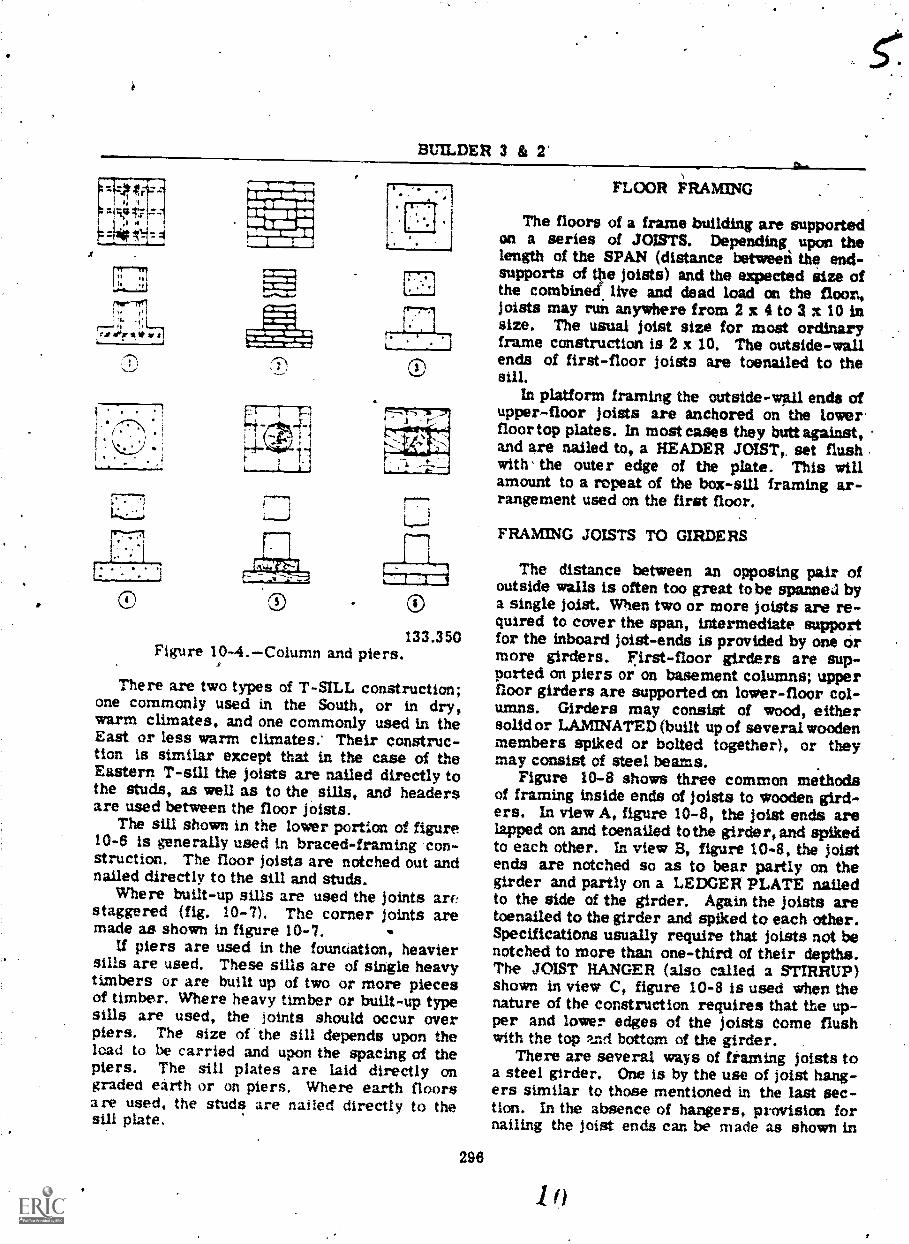
The work involved in sill construction is avery important one for the Builder. The founda-tion wall is the support upOn which'all structurerests. The sill is the foundation on which allframing struepre rests 'and it is the real pointof departure-for actual building and joinery ac-tivities. The sills are the first part of theframe to be set in place. They rest either di-rectly on the foundation piers or on the ground,and may extend all around the building; et6r arejoined at the cornes and spliced, when neces-sary. Figure 10- shows some common typesof sills. The type used depends upon the gen-eral type of construction used in the frame.
BOX sills are used often with the very com-mon style platform framing, either with orwithout the sill plate. In this type pf sill, thepart that lies on the foundation wall or groundis- called the sill plate. The sill is laid edge-wise on the outside edge of the sill plate,'
BUILDER 3 & 2'
ill=1101IMIMENIMMO,
Oillib iaws.ftwo INOMPft.
etkgs0ablielSPISV
®133.350
Figure 10-4.Column and piers.
There are two types of T-SILL construction;one commonly used in the South, or in dry,warm climates, and one commonly used in theEast or less warm climates: Their construc-tion is similar except that in the case of theEastern T-sill the joists are nailed directly tothe studs, as well as to the sills, and headersare used between the floor joists.
The sill shown in the lower portion of figure10-6 is generally used in braced-framing con-struction. The floor joists are notched out andnailed directly to the sill and studs.
Where built-up sills are used the joints arr!staggered (fig. 10-7). The corner joints aremade as shown in figure 10-7.
If piers are used in the founuation, heaviersills are used. These sills are of single heavytimbers or are built up of two or more piecesof timber. Where heavy timber or built-up typesills are used, the joints should occur overpiers. The size of the sill depends upon theload to be carried and upon the spacing of thepiers. The sill plates are laid directly ongraded earth or on piers. Where earth floorsare used, the studs are nailed directly to thesill plate.
296
FLOOR FRAMING
The floors of a frame building are supportedon a series of JOISTS. Depending upon thelength of the SPAN (distance betweeri the end-supports of the joists) and the expected Size ofthe combined live and dead load on the floor,joists may run anywhere from 2 x 4 to 3 x 10 insize. The usual joist size for most ordinaryframe construction is 2 x 10. The outside-wallends of first-floor joists are toenailed to thesill.
In platform framing the outside-wall ends ofupper-floor joists are anchored on the lowerfloor top plates. In most cases they butt against,and are nailed to, a HEADER JOLST,, set flushwith' the outer edge of the plate. This willamount to a repeat of the box-sill framing ar-rangement used on the first floor.
FRAMING JOISTS TO GIRDERS
The distance between an opposing pair ofoutside walls is often too great tobe spanned bya single joist. When two or more joists are re-quired to cover the span, intermediate supportfor the inboard joist-ends is provided by one ormore girders. First-floor girders are sup-ported on piers or on basement columns; upperfloor girders are supported on lower-floor col-umns. Girders may consist of wood, eithersolid or LAMINATED (built up of several woodenmembers spiked or bolted together), or theymay consist of steel beams.
Figure 10-8 shows three common methodsof framing inside ends of joists to wooden gird-ers. In view A, figure 10-8, the joist ends arelapped on and toenailed to the girder, and spikedto each other. In view B, figure 10-8, the joistends are notched so as to bear partly on thegirder and partly on a LEDGER PLATE nailedto the side of the girder. Again the joists aretoenailed to the girder and spiked to each other.Specifications usually require that joists not benotched to more than one-third of their depths.The JOIST HANGER (also called a STIRRUP)shown in view C, figure 10-8 is used when thenature of the construction requires that the up-per and lower edges of the joists come flushwith the top and bat= of the girder. .
There are several ways of framing joists toa steel girder. One is by the use of joist hang-ers similar to those mentioned in the last sec-tion. In the absence of hangers, provision fornailing the joist ends can be made as shown in

Chapter 10--FOUNDSTION CONSTRUCTION .AND FLOOR AND WALL RAMING
133 51Figure 10-5. Braced piers, sills, girders, and joist construction.
figure 10-9. In view A. figure 10-9, the joistends are lapped on and toenailed to a x 4,*Mob is itself bolted to the upper FLANGE ofan I-BEAM girder. The joists are also spikedto each other. In view B, figuze 10-9, the endsof the Joist are shaped to ft around the upperflange. The ends are butted to each other andeach end is anchored on, and toenailed tog a2 x (which is bolted to the WEB (vertical part)of the girder. The joist ends must be shovedso as to leave an allowance of about 3/8 in. (for2 x 10 joists) above the top of the girder, asshown. This is a SHRINKAGE ALLOWANCE,so called because it allows the wood to shrinkwithout causing the joitt enda to split ca thegirder flange.
FRAMING AROUNDFLOOR OPENINGS
Where a floor opening occurs (such as astairway opening), the parts of the commonjoists which wonld extend across if there wereno opening must be cut away. The segmentsremaining co either side of the opening 'arecalled CRIPPLE or TAIL joists. The wall-ops:wing ends of cripples are framed against
297
HEADERS as shown in figUre 10-10. Specifica-tions usually require that headers be doubled.-sometime s tripled.
Headers are framed between the full-lengthJoists which lie on either side of the floor open-ing. These joists are called TRIMMERS, andthey, too, are usually doubled or tripled. Head-ers up to 6 ft in length are fastened with 20-penny nails, driven through the trimmers intothe ends of the headers. Headers more than 6ft in length should be fastened with joint hangers.
FLOOR FRAMING UNDER PARTITION
A PARTITION is a wall other than one of theoutside walls of the structure. An upper-stor,partition is not always supported by a partitionlocated directly under it on the story below.When it is not, tlie floor must be strengthenedto carry the load of the partition. For a parti-tion running pamliel to the lines of the foists,strengthening is accomplished by doubling thejoist under the partition (fig. 10-11).
The joist is doubled by nailing two joists toa series of SOLID BRIDGES, usually placedfrom 14 to 20 in. O.C. The bridges must sepa-rate the 'oists by the width of the partition sole

BUILDER 3 & 2
SOLEX 4 PLATE
STuOS
susFLOOR
ORAFT- STOP. HEADER
STuOSSiLL PLATE
/FRESHmORTAR
JOISTS
SOLEPLATE
NCHOR BOLT
BRICN BEAM g'IL L
ST45 S
s;LL. PLATE
CONCPCEFCuNDAT c;)N
x 4 STUDS
SuEtIrLOOR
HEADER
SI L PLATE
JOiST SCONCRETE
FOUNDATION
CvNOATIONTWALL
JOtST
SOLEPLATE
SILL
PIER
FOOTING
JOIST ,
FRES;.4 MORTAR
133.352Figure 10-6.Types of sills.
plate, to ensure that the upper edges of thejoists will be available as nailing surfaces forthe finish flooring. Sole plate stock, cu:: inlengths equal to the depth of the joist, is thebest mater,ial to use for the bridging.
For a partition which runs across ratherthan parallel t9 the joists, every ,other joist inthe floor (or every )oist, if so specified) isdoubled in the same manner.
BRIDGING
The system of bracing the joists to eachother is called BRIDGING. The chief purposeof bridging is to hold the joists- plumb and incorrect alignment, but bridging also serves to
298
FIure 10- Sill fabrication.
distribute part of a concentrated heavy load(such as the weight of a piano) over severaljoists next to those directly under the load.
There are two types of bridging: eRossbridging (view A, fig.10-12) and SOLID bridging(view B, fig. 10-12). Cross bridging consists ofpairs of STRUTS (commce sizes of strut stockare 1 x 3, 1 x 4, 2 x 2, 4nd 2 x 4), set diagonallybetween the joists. Solid bridging consists ofpieces of joist-size stock set at right angles tothe Joists and can be staggered for easier in-stallation.
Since cross bridging in More effective thansolid bridging, cross bridging is the type mostfrequently used in modern construction. Forjoist spans of ordinary length, specificationsusually require a row of cross biidging forevery 5 to 8 ft of span. For =usually longspans, the maximum distance between rows ofbridging is about 6 ft.
The required length of a cross-bridging strutand the required angle of cut for the ends maybe figured as follows: select a piece of boardequal in width to the ACTUAL depth of a joist,and 4 or 5 in. longer than Ole specified spacingof joists O.C. Square two lines across thebogrd, separated from each other by a distance

Chapter 10FOUNDATION CONSTRUCTION AND FLOOR AND WALL FRAMING
A
MID GIRDER
Figure 1O-8.Methods of framing joists to wooden girders,
JOISTS APPED
JOIVS BUTTED3/8" SHRINKAGE
ALLOWANCE
133.91
TOENAIL
BOLT
-4-- 2 4
Figure 10-9.Methods of framing joists to steel girders.
between the two joists. These two lines repre-sent the opposing faces of two adj4cent joists.
Next, sketch in the edge outline of one of thestruts, as shown in figure 10-13, using the AC-TUAL thickness of the in,terial. The measuredlength of this outline is thc -equired length. of aItrut. To cut struts to this length and le :hecorrect end-angle, proceed to make a miter ixas follows:
133.92
First, edge-butt a length of 2 X 4 to a lengthof 2 x 6, as shown in the second ind third views
i'of figure 10-14. Then set the framing squareon the layout as shown in the first view with aconvenient figure on the tongue intersected bythe lower end of the strut outline. Note thefigure that the outline intersects on the blade,as indicated. Set the framing square to thiscut en the upper edge of the 2 x 6, as shown in
299

ER 3 & 2
this point, as shown in the third view. Strutsmay now be Sawed ..orrect length and correctangle by placing the strut stock on edge in themiter box with the end against the stop block.
The, bridging is installedafter the joists havebeen set in place, lyit before the subfloor is laid.At this time only the upper ends'oghe strutsare nailed. The nailing of the lower ends ispostponed until after the joists have adjusted tothe weight of the subflooring.
SUB.FLOORING
Since the subflooring helps to hold the joists. phimb and rigid, it is considered to be a struc-tural eleinent- and therefore a part of the fram-ing. The specifications usually refer to the
133.93 subflooring in language similar to the following:Figure 10-W.Framing around floor opening.
the second view, and draw a line along thetongue.
A kerf sawed square from this line will guidethe sa* at the correct angle for maktivg the endcuts. Nleasure off from the kerf the length of atrut, and nail a stop block to the miter box at
JOIST
.0-4-PART IT IONSTUD
PARTITIONSOLE F,LATE
*IOTH OF BRIDGINGS E AS *IDTH OF
PARTITION SOLE PLATE
JOIST
Subfloors. Joists shall be floored with No. 2common 6-in, sheathing, laid close and straight[or diagonal] and double-nailed at each joistcrossing.
Unless otherwise specified, lumber for sub-flooring is usually square-edged. Unless boardsare END-MATCHED (shaped on the ends to
Figure 10-11.Method of doubhni: t nder partition.
300el
133.94

Chapter 10FOUNDATION CONSTRUCTION AND FLOOR AND WALL FRAMING
JOIST
45.440Figure 10-12.Cross bridging and
solid bridging.
form tongue-and-groove end joints), they mustbe cut so as to bring end joints over joists.
Wood flooring expands considerably when itis wetted, and the subflooring may be wettedrepeatedly during construction operations. Ifthe flooring were laid so as to buttagainst theinner faces of studs (for example), expansion ofthe subfloorinwcould push the studs out of line.Besides the marginal expansion space, a spaceof about 1/2 in. should be left between boardsat intervals of about 6 ft across the floor.
Straight-laid subflooring is laid at a 900angle to the lines of the joists; diagonal-laidsubflooring at a 450 angle. To ensure that thelines of end joints will be parallel to the linesof the joists, straight-laid boards must be cut
301
cou square, and diagonal-laid boards miteredto 45°.
Straight-laid subflooring is started at a wallline; Aiagonal-aaid sualooring at a corner. Thefirst board laid is called the STARTER BOARD.The starter board for diagonal-laid subflooringis a small piece shaped like a 450 triangle.
'Subflopring is nailed down with two 8-penny,nails at aach lolst crossingwith 4 nails (2 ineach board) at every crossing .where an endjoint between boards occurs.
WALL FRAMING
Wall framing (fig. 10-15) is composed ofregular studs, diagonal bracing, cripples, trim-mers, headers, and fire blocks and is supportedby the floor sole plate. The vertical membersof the wall framing are the studs, which .supportthe top plates and all of the weight of the ;overpart of the building or everything above the tOpplate-line. They provide the framework to /hichthe wall sheathing is nailed on the outside-andwhich supports the lath, plaster, and insulationon the inside.
Walls and partitions which are clasfed asfrained constructions are composed of struc-tural elements (fig. 10-16) are usually closelyspaced,slender, vertical members called studs.These are arranged in a row with their ends6earing on a long horizontal member called abottom plate or sole plate, and theirlops_cappedwith another plate, called a top plate. Doubletop plates are used in tearing walls and parti-tions. The bearing strength Of stud walls isdetermined by the strength of the studs.
CORNER POSTS
The studs used at the corners of the frameconstruction are usually built up from three ormore ordinary studs to provide greater strength.These built up assemblies are comer-partition-posts. After the sill and first-floor joists arein place, the sub-floor is placed to give a sur-face upon which to work. The corner posts areset up, plumbed, and temporarily braced. Thecorner posts may be made in several differentways (fig. 10-17).
A corner post may consist of a 4 by 6 with a2 by 4 nailed on the board side, flush withone edge. This type corner is for a 4-inchwall. Where walls are thicker, heavier tim-ber is used.

BUILDER 3 & 2
OJS1hN BETWEENd
JOIST ACT4AL TOOMESSOf STRUT STOCK
ACTUAL. DEPTHOF JOIST
LENGTHOF STRUT
Figure I 0-13.Layout for cross-bridging strtdat.
A 4 by 4 may be used with a 2 by 4 nailed totwo of the adjoining sides.Two 2 by 4's maya be naild together withblocks between and a 2 by 4 flush with oneedge.A 2 by 4 may be nailed to, the edge of another2 by 4, the edge of one flush with the side ofthe other. This type is used extensivulywhere no inside finish is required.
Whenever a partition meets an Outside wall,a stud wide enough to extend beyond the parti-tion on both sides is used, this affords a solidnailing base for the inside wall finish. Thistype of stud is called a T-POST and is made inseveal. different ways (fig. 10-18).
A 2 by 4 may be nailed and centered on theface side of a 4 by 6.A 2 by 4 may be nailed and centered on two4 by 4's nailed together.Two 2 °by 4's may be nailed together-with ablock between them and a 2 by 4 centered onthe wide side.A 2 by 4 may be nailed and centered on theface side of a 2 by 6, with a horizontalbridg-ing nailed behind them to give support andstiffness.
Where a paztition is finished on one sideonly, the PARTITION POST used consists of asimple stud, set in the outside wall, in line with
133.95
the side of the partition ws11, and finished asstud A in 1, figure 10-10. These posts arenailed in place along with the Corner poet. Theeltact position of the partition walls anust bedetermined before the posts are placed. Wherethe walls are more than 4 inches thick, widertimber is used. In special cases, for examplewhere partition walls does, a double T-post isused. This is' made liy using methods previouslydescribed and nailing another 2 by 4 to the op-posite wide side, as shown in 2, 3, and 4, figure10-19.
STUDS
After the poets, plates, and braces are inplace, the studs are" placed and nailed with two-18- ior 20-penny nails througii the top plate.Before the studs are set in place, the windowand door openings are laid out. Then the re-maining or 'intermediate studs are laid out onthe sole plates by measuring from one cornerthe distances the studs are to be set .apart.Studs are normally spaced 12,18, and 24 inchescm centers decending upon the type of buildingand the type of outside and inside finish. Wherevertical siding is used studs are set widerapart since the horizotal girts between themafford nailing surface.
When it is desirabl, to double the post of thedoor opening, first place the outside studs intoposition and nail them securely. Then cut short

Chapter, DOFOUNDATION CONSTRUCTION AND FLOOR AND WALL FRAMING
't
A.
t:0
.1r ,
133.96Figure 10-14,Making a miter box for
cutting cross-bridging struts.
studs, or FILLER STUDS, the size of the open-ing, and nail these to the inside face of the out-side studs as shown in figure 10-151 In makinga window opening, a bottom header must beframed; this header is either single or double.When it, is doubled, LI* bottom piece is nailedto the opening studs at the proper height and thetop piece of the bottom header is nailed intoplace flush- with the bottom section. The doorheader is framed as shown- in figure 10-15. Thefiller stud rests on the sole at tne bottom.
TOP PLATE AND SOLE PLATE
The top plate serves two purposes to tiethe studding together at the top and form a fin-ish for the walls; and. to furnish a support forthe lower ends of the rafters (fig. 1.0-15). Thetop plate serves as a connecting link betweenthe wall and the roof, just as the sills and
303
girders are connecting links between the floorsand the walls. The -plate is made up of one ortwo pieces of timber of the smite size as thestuds. (In cases where the -studs at the end'ofthe i.tilding extend to the rafters no plate isused at the end of the building.) When it is uredon top of partition walls, it is sometimes calledthe cap. Where the plate is doubled, the firstplate or bottom section is nailed with 16- or20-penny nails to ihe top of the corner ,postsand to the studir-the connection at the coriher ismade as ,shown in 1, figure 10-20. Alter thesingle plate--is nailed securely and -the corner.braces are nailed into place, the VII part of theplate is then 'nailed to the bottom, section bymeans of 16- or 20-penny nails either over eah-stud, or spaced with two nails every 2 feet. eedges of the top seetion should be flush with;the bottom section and the corner joints lappeglas shown in I and 2, figure 10-20.
All partition walls and %outside, walls arefinished either with a 2 by 4 or with- a piece oftimber correspontling to the thickness of thewall; this tim r is 1ai4 horizontally on thefloor or joists. It carries tHe bottom end of.thestuds (fig. 10- This 2 by 4, or,timber, iscalled the "sole or ''soleshould be nailed with titro' 16-at each joist that it trosses.wise on top of a girder opknailed h two nails every 2
PARTI
Partitionside spacecases arecases where floutside of thetion walls are
plate." The solebr 20-penny nailsU it is laid length-joist, it should befeet.
a
walls are walls that,divide the in-building. These walls in most
ed as part Of the building. Ins are to be installed after theding is completed, the part-
eft unframed. There are twotypes of partit on walls: the bearing, and thenonbearing types. The bearing type supportsceiling joists. The nonbearing type supportsonly itself. This type may be put in at anytimeafter the other framework is installed. Onlyone cap or plate is used. A sole plate should beused in every.case, as it helps to distribute theload over a larger area. Partition walls areframed in the same manner as outside walls,and door openings are framed as outside open-ings. Where there are corners or where onepartition wall joins another, corner posts orT-posts are used as in the outside walls; theseposts provide nailing surfaces for the insidewall finish. Partition walls in a one-story

BUILDER 3 & 2
DOUSLETOP PLATE WNW., ST up 44
C K
1111.II IllS
...ermaNEAOERLAID ON
EDGE
411.3.. LAIO FLAT
ADE!LAU) QN
EDGE
TRomMER
IliCRIPPLE STU
SY %OWLS
COMMON STUDTRINM'ER Stu()CRIPPLE STUD
SOLE-PLATE
TYPICAL WALL FRAMING
SO E 'PLATE LAYOUT
Figure 10-15.Typical wall frame details.building may or may not4extend to the roof. Thetop of the studs has a plate when the Vali doesnot extend to the, roof; but when the \wall extendsto the roof, the studs are Joined t6 the rafters.
BRACES
Bracing stiffens framed construction andhelps it to resist winds, storm twist, or Strainstemming from any cause. GoOd bracing keepscorners square and plumb and prevents warpingsagging, and shifts resulting from lateral forcesthat would otherwise tend to distort the frameand cause badly fitting doors and windows andthe cracking of plaster. 'there are three com-monly used methods of bricing frame struc-tures.
304
133.354
Let-in bracing (1, fig. 10-21). Let-in bracingis set into the edges of studs so as to be flushwith the surface. The studs are, always cut tolet in the !Ayes the braces are never cut.'Usually 1 by s or 1 by e's are used, set diag-onally from top plates to sole plates.*
Cut-in bracing (2, fig. 10-21). Cut-in bracingis toenailed betweewstude. It usually consistsot 2 by 4/s cut at ait angle to permit toenailing,inserted in diagonal progression betteen studsrunning up and down froth corner posts to sillor plates.
sheathing (3, fig. 10-21). The typeof b with the highest strength is sheathingapplied diagonally. Each boaid acts as a braceof the wall. U plywood sheathing 5/8-inch thickor more- is used, othefalmethods cd bracing maybe omitted.
I
4

10FOUNDATION CCNS7RUCTION AND FLOOR AND WAJA FRAMING.1111C
2 It 4 POUSLE TC,P PL ATE ACC-5Z1T-11z WALL SECTICO TOGETKR -
+4 3
1%15 BiACE
21 4 SC...,E
OR[NG
\NALL SECrioN iNPLACEAi;TH TEMPORARY BRACING
Figure 10-18.Typica1 wall construction.
13 4541Figure 10-17. Corner post construction:
FRAMING LAYOUT AND ERECTION
Framing LAYOUT consists principally oflaying out the various framing members forcutting to correct lengths, and marking thecorrect locations of members on other mem-bers to which they are to be joined.
SILL LAYOUT
The sill is normall) the first member to belaid out. As indicated in figure 10-1, thot edge
305
®
4 TOPPLATE
4 Er C NG
2 4 S T
133.355
33,357Figure 10 18.T-post construction.
of the sill Is usaally set back fronr the edge ofthe foundation a distance equartp the thicknessof the Iheathing. When this is the case, thelength af ;itll stock req4ired_to cover a.seqionof foundatlm wall a: evil to the length of thewall section minus twice the aitnamt of thesot-back..
To -make up thIlength you should sfslectlengths of sill/ stock which will most c,xwen-
tiéntly and eccinomically make up the total re-quired length. Suppose, for example, that thesectkm of wait calls for 334ft of 2 x 8 sill stock
f'

BUIL ER 3 & 2
133.358Figure 10-19.Partition posts.
and you have 2 x 8 available in 18 ft; 1 ft,14-ft, and 6-ft lengths. You could select two18-ft pieces anclCut-3 ft off one of them, or youcould select two 14-ft pieceS and a 6-ft pieceand cut a foot ofX the- 6-ft piece.. In the\ firstinstance, however, you would have 3 ft of waste,while in the second you would have Palo joints inthe sill. To minimize both waste and the ;lim-ber of joints, you shoUld select one 18-ft andone 16-ft piece and cut 1 foot off one of them.
Once the required length lias been _made up,the next step is to lay out the locations of-the'bolt holes as follows: place each piece of sillstock co the foundation, inboard of the bolts,but otherwise in exactly the position it is tooccupy,and square a line across the stock from
133.358Figure 0-20. Plate construction.
the "canter of each bolt To lay Out the bolt-holecenter on each of these lines, measure the dis-tance froni the center OF EACH BOLT to theouter edgeof the foundation; subtract the *mountof the sillset-back from this distance, and layoff the remainder ON THE CORRESPONDINGBOLT LINE, measuring from what is to be theouter edge elf the sill.
The reason you must lay out each bolt holeseparately is that the bolts may be set atslightly varying distances from the edge of thefoundation an4 from each other.
SILL PLACEMENT
Bore the bolt holes with an auger bit 1/8 in.larger in diameter than the bolt diameter,. toallow for making 3light adjustments in the loca-tion of the sill. When all the holes have beenbored, try the stock for the whole section on.the bolts for a fit. If the fit is satisfactory, re-move the pieces of stock and place a thin layer
, of mortar on top of the foundation. Replace thepieces and check the whole sill for line andlevel. Place small wedges, if necessary, to holdpieces level until the mortar sets. Then placethe washers on the bolts, screw on the nuts, an4bolt the sill down.
JOIST LAYOUT
A COMMON JOIST is a full-length Joist, asdistinguished from a cripple joist. The bestway to lay out common joists for cutting is tofigure the correCt length of a common joist,
30621)

-
,e .,
Chapter 10L OUNDATION C(iSTRUCTION AND FLOOR AND WALt 'FRAMING\ lh
Figure 10-2 Common types of bracing.
307
.133.103
1/
1,
..
v

BUILDER 3 & 2/
cut a piece of stEick to this Lenith, notch foridentification, and use the piece as a PATTERNfrom which to cut the other commonjoists. Thebest way to lay out cripples for cutting is topostpone the cripple layout until after the Cs.sd-ers have been placed: then measure the spaceswhich are twbe spannedty_lhe cripples.
In platform framing, the outer ends of pejoists usually butt,against a header joist whachis set flush with the ,outer edge of thesill. Inthis case the length cirla wall-to-wall commonjoist, will be the 'distance between the outeredges of the sills, minus twice,the thickness ofa header joist. .
The length of com5ion joist required to cover:1--rtven span betyeen an qutside wall and agirder varies with the scharacter of the wirllframin% and also . with the manner in which thejoists are framed to the girder. The length ofcommon joist required to cover a given tnianbetween two gArders varies with the manner inwhich the joists are- 'framed to the girdexs.Joists which lava girder with full bearing(meamng joists which extend all the way across
-the top of the girder) must obviously be Icfgerthan joists vhich butt each other on the top IA agirder. Joi3ts in hangers, which butt agathe sides 9f a girder, are4shorter than joiswhich butt each other on top.of a girder.
The whole floor-framing situation, theniMust be studied closely, before a common joistpattern'is cut. Whenever possible, the cutting:of a pattern should be delayed untft the sills,headers, and other supporting or abutting mem-bers are erected.- The joist length can then bedetermined by measurements taken on the ac-tual structure. Wllenever possible, too, thecommon joist pattern Should be, tried on the ac-tua' structure fqr a fit before any joists arecut from it.
JOIST LOCATION LAYOUT
The location ,of a joist end is %narked on a4sill or a header joist by squaring a line ac.rossand drawing an X alor.gstde -it. The X indicatesthe side of the tine on which the joist end-sectionis to be placed.
The locati:Ai of' one of the outside joists ismc.irkecl,first, and the locations of the othersare then measured off from this one in accord-ance with thu specified spacing of joists O.C.
Figure 10-22 shows the method of laying, outjoist locations on the header joists in a platform-frame box sill, in which the headers and outside
is
joists come flash with the outer edges of thesill.
Before you start laying out the joist loca-tions you should study the floor framing plai tolearn the locations of any double trimmersaround floOr openings. Locations of doubletrimmers are marked with two lines and twoVs. The locatiqpikOf cripples are marked thesame as the location's of common joists, butwith the word CRIP written in alongside.
JOIST ERECTION
The usual procedure for erecting joists is aslows: if there are any header joists, thesests are cut and erectf : first.' AS a general
rule, the length of a platformqrame header isequal to the shortest distance between the outeredges of the sills. Header'joists are toenailedto the sills with 16-penny nails spaced 16 in. 0.C.
As soon as a cornmonjoist pattern has beenlaid out and cut as previously described, aCUTTING PARTY starts cuttisg common joists.'As each joist is cut, a 2-man CARRYING PARTYcarries, it to its location and lays it flat acrossthe span. A 2-man CONSTRUCTION PA(one 'man at each end of the span) erectsoutside Joists first. Each of these is toenaileddown to the sill or plate with 16-penny , nailsspaced 16 in; O.C., ahd end-nailed through theheaders with two 20-pOny nails driven intoeach joist end. Incldepitally, many joists havea slight curve' to them, and the convex edge ofa joist is called the CROWN: A joist shouldalways' uk: placed with the crown UP.
Next the joists lying between the' outsidejoists are set on edge and the ends of each joistare toenailed down to the sill or plate with two16-penny nails, one .on each side of the joist.Only the inner trimmer of each pair of trim-mers is 4.fected at this time, and no crippl sare cut at this time. Alter all the common
.,joists, and the trimmers as mentioned, havebeen set on edge and toenailed, the joists areplumbed and temporarily braced as follows.
A temporary brace (usually a 1 x 6) is laidacross the s of the joists at the center of thespan.. The ou r ends of this brace are tackeddown to t outside joists with 8-penny nails,driven oni part-way in to allow for extractinglater when ti* brace is removed. Beginningwith the joist next to an outside joist, the joistsare plumbed consecutively; and as each joistis plumbed it is braced with an 8-penny nail,driven through the race into the joist.
3089 9

133.105Figure 10-23 Firet step in framing-around floor opening.
each end, driven through the trimmers into theends of the headers (fig. 10-25). Finally, theoutside trinuners are set in place and nailed tothe inside trimmers with 16-penny nails spaced12 in. O.C., as shown in figure 10-26.
As soon as enough common joists have beenerected, the installation of bridging begins.Cross-bridging struts are nailed' (usually with8-penny nails) at the 'top ends only at this time.Bottom_ ends will be nailed, from below., afterthe joists have adjusted themselves to Theweight -Of the subflooring. Remember the joistshould be placed with the crown up, so that anysettlement wader the weight of the flooring willtend toward a level instead of toward a sag.
After the bridging is installed, the svAbfloor-ing is laid as previously described. In themeantime, th9 layout and cutting of studil begins.
LAYING OUT STUDS FOR CUTTING
Before you can lay out any studs for cutting,you must calculate how long the studs must be.The best way to do this is to lay out to full scalecm a piece of stud stock certain data obtained
310
from the wall sections and elevations, and thenuse the, piece of stock as a pattern for cuttingstuds.
Next step is to .lay out the segments of thegable-end studs which extend above the level ofthe top of the rafter plate. In erder to do this,you stoat calculate the COMMON DIFFERENCEof gable-end studs as follows.
In figure 10-27 the line AC indicates thelevel of the gide wall rafter plate, and line ABindicates the roof line of the building. 'Some-where on the elevations you will find a smalltriangle like the one shown in the upper left ofthe figire. This is called the ROOF TRIANGLE,and it gives the proportion of run to Mao in therocd. In thhaacase this is also the proportion ofnit to rise betwebn line AC and line -AB, andthe proportion is 8 inches of rise to every 12inches of ,run.
The lines DE and FG represent the portionsof two gable-end studs that extend above thelevel of the top of the sidewall rafter plate.You can calculate the length of DE as follows:Since the 'tads are awed 16 in. O.C. the runof the right triangle An) is 16 in. The rise of

Chapter I0FOUNDATION CONSTRU ON AND FL.00R AND WALL FRAMING
Figure 10-22. oist location layoutplatform e box sill assemblywith header joists.
A joist that butts against a header is plumbedby lining up the joist end with the pemendicularlocation line on the header. When the joist isin plumb position, it is nailed at the ends With20-penny nails, 2 to each end, driven throughthe header into the joist.
Aftee all the common joists, plus the ipsidetrimmers (if there are any), have been plumbedand braced, the framing around a floor opening(if there is one) is installed. Firstthe locationsof the headers are determined from a. study ofthe floor framing plan. Next the length of aheader is determined by measurement of theshortest distance between the Inside trimmers.The four pieces of )oist stock which will formthe double headers are then cut to correctlength, after which the outside header of each
309
133.104
pair is set in place and fastened to the insidetrimmers with 20-penny nails, three to eachend, driven through the trimmers into the endsof the headers as shown in figure 10-23.
Once the outside headers are in place, thelengths of the cripple joists can be determinedby simple meastrement. The cripples are cut,set in place, plumbed, fastened at the outerends like common joists, and fastened at thefloor-opening ends with 20-penny nails, threeto each cripple, driven through the outsideheaders into the ends of the cripples as shownin Figur* 10-24.
Next the inside headers are set in place,fastened to the' outside headers with 16-pennynails spaced 6-in. O.C., and fastened to the in-side trimmer% with 20-penny nails, three to

Chapter 10--;FOUNDATION CONSTRUC AND FLOOR AND WALL FRAMING
133.106Figure 10-24.Second step in framing around, floor opening.
this triangle is the length of the line DE. Fromthe roof triangle you know that the rise of asimilar triangle with a run of 12 in. is 8 in. Ifthe rise of a right triangle with krun of 12 in.is & in., the rise of a similar right triangle witha run of 16 in. must be the value of x in theproportional equation 12:8:16:x, or 10 2/3 in.The length of DE, therefore, is 10 2/3 in.Rounded off to the nearest 1/16 in., this is10 11/16 in. The common difference may alsobe found as follows. Multiply the cut of theroof, expressed as a fraction, by the spac-ing of the studs. Assume a roof cut of 8 in. and12 in. and a stud spacing of 16 in. The commondifference in the length of the gable stud is 16in. x 8/12 in. = 10 2/3 in. Expressed as a for-mula, stud spacing x cut of the roof z commondifference.
If the rise of a right triangle for 16 in. ofrun fs 10 11 '16 in., the rise for twice as muchrun, 'or 32 in., must be twice as much, or 2 x
-IP 11/16 in.; the rise for three times as muchgun must be 3 x 10 11/16; and so on. Thismeans that, moving inboard from the rafter
311
plates, each gable-end stud i Ei 10 11/16 in.longer than the preceding gable-end stud.
Knowing this, you can lay off the lengths ofthe gable-end studs by laying off 10 11/16 in.(which is tailed the COMMON DIFFERENCE ofgable-end studs) progressively foi each stud,from the shortest to the longest, in either sideof the end wall. The top end cut of the gablestud is laid out by using the cut of the roof andmarking on the rise side.-
A pattern layout for platform-frame studsis shown in figure 10-28. Since the bottom of aplatform-frame stud.rests on the sole plate,which in turn rests op the subflooring, youshould first lay off the vertical distance betweenthe finish floors. MINUS the thickness of thesole plate, PLUS the thickness of the finishfloor. This is distance 1 in figure 10-28; layingit off will 'give y6u the level of the upper finishfloor. Lay off back from this leVel the com-bined thickness of the upper floor flooring, thedepth of an upper floor joist, and the thicknessof the top plate. You now have the length of astud, as shown in the figure.

BUILDER 3 & 2
133 .107Figure 10-25.Third step in framing around floor opening.
STUD LOCATION LAYOUT
Stud locations are marked on sole plates inthe same manner as joist locations. The soleplate is marked first, as shown in figure 10-29.Thetie marks are then transferred to the cor-responding top plate or rafter plate, by "match-ing" the top plate or rafter, plate against themarked sole plate. and squaring the marksacross.
The studs around wall openings require spe-cial treatment. First locate the center line ofthe openingty examining the floor plan.. Let'ssay that the opening is a door, and that the planshows that the center line of this door lies 7 ft5 in. from one of the buildingcorners. Measurethis off and square a line across the sill orplate at this point. Next look, on the door sched-ule and find the width of this door. Let's saythat it is Door A, and you find that Door A is3 ft wide. Lay off ane-half of this, or 1 ft 8 in.,on either side of the center line and squarelines across.
312
FRAMING ALLOWANCE
These lines mark the boundaries of the FIN-ISHED door opening. The trimmer studs oneither side of the opening, however, must belocated at the boundaries of the ROUGH opening.To get the width of the rough opening you add aFRAMING ALLOWANCE to the width of thefinished opening. First, the width of the roughopening must exceed the width of the finishedopening by the combined thicknesses of theSIDE JAMBS on the door, less the combinedwidth of the rabbets if the door fits into`rabbetscut in the side jambs.
Besides the allowance for the thickness ofthe jambs, you must make an additional FRAM-ING ALLOWANCE. As you will ,see later, theside jambs are wedged in place with woodenwedges, driven between the Jambs and the trim-mers. The usual wedging allowance is 1/2 in.on either side.
The width of the finished opening (whichis the same as the width of the dour) is the

Chapter 0 FOUNDATION ONSTRUCT1ON AND FLOOR AND WA FRAMING
133.106Figure 10-26.Fourth step in framing around floor opening.
horizontal distance between the side jambs.The width of the rough opening is the samehorizontal distance, plus the combined width ofthe jambs, plus the combined width of the wedg-ing allowance.
To locate tlie trimmers, then, lay off, oneither side of the center line, one-half thewidth of the door, plus the thickness of a sidejamb (which should be meuured on the actualstock), plus the wedging allowance (usually1/2 in.). Mark the trimmer locations with theword T and postpone the cutting of thet.rimmerk until after the header has been cutand set in place.
The header will be nailed between the firsttwo full-length studs lying outside the bounda-ries of the finished opening. To locate theheader at the right height you must add to the
,height of the door a framing allowance as fol-lows. You must make allowance for the thick-ness of the head jamb, and also for the depth ofthe SIDE JAMB LUGS. The side jamb lugs are*Iv portions of the side jambs which extendabove the head iamb dadoes. Since you will be
313
measuring from the top of the subflooring andsince the bottom of the door 'will have to clearthe finish flooring, you must allow for the thick-ness of the finish flooring. U there is to bethreshold under the door, you must allow forthe thickness of the threshold. If there will beno threshold, you must add a CLEARANCEALLOWANCE which will permit the door toswing clear of any rugs or carpets. The usualclearance allowance is 5/8 in., which is alsothe usual thickness of-a threshold. If the car-peting is to be extra thick, the clearance allow-ance may have to be more than 5/8 in.
The framing allowance for 'a window openingis calculated as follows: locate and mark thewindoW center line and lay off on either side ofthe center line one-half the width of the window,as obtained from the window schedule. Thiswill locate the limits of the finished windowopening. The top header and subsill header willbe set between the first two full-length studslying outside these limits.
Further window-opening layout should bepostponed until the subsill header has been set

BUILDER 3 & 2
133.109Figure 10-2'7 Calculating common
difference of gable-end studs.
in place. The height of the subsill header isobtained as follows: determine by examiningthe appropriate elevation, the height of the topof the window sill above the finish flooring.Since you will be measuring from the subfloor-ing, add the thickness of the finish flooring.From this, subtract the thickness of the windowsill, plus the sill BEVEL ALLOWANCE, oramount that the sill will be raised by tilting.This is usually about 3/4". To sum up, theheight of the tcj of the subsill header above thefinish flooring will be the vertical distance
between the top of the window sill and the top ofthe finish floor, MINUS the thickness of thewindow sill, the sill bevel allowance (usually3/4 in.), and the thickness of the finish flooring.
The next step is to locate the top header atthe proper height. One* elevation you will findthe vertical distance between the finished firstfloor line and the bottom of the window headjamb. Since you will meastire this distancefrom the top of the subfloor,.add to it the thick-ness of the finish floor. Next add the thicknessof the head Jamb plus the depth of the windowside jamb lugs, which are similar to those on adoor. The total will be the vertical distancebetween the top of the subfloor and the bottomof the top header.
When you have located the level of the bottomof the top header, check the whole layout asfollows. You know that the height of the roughopening should be the height of the window (asgiven on the schedule) plus the total framingallowance. Calculate the total framing allow .ance yoti have applied and add it to the windowheight. The result should be the same as themeasured vertical distance between the top of
, the subsill header and the bottom lof the topheader. If it isn't, you have made a mistakesomewhere.
To locate the trimmers proceed as follows:transfer the window center line to the subsillheader and lay off on either side of it one-halfthe width of the window, as obtained from thewindow schedule. For a window without sash
vERTICAL DISTANCE BETINEEN fINIISM Ft. C'PS
-,C.NEss 'NISH crp
CC\
rHICKNESS SDLc PA E
...ENC,T04
1- -
Figure 10-28. Pattern
314
e st'133.110

Chaptee 10FOUNDATION CONSTRUCTION AND FLOOR AND WALL FRAMING
, Figure 10-29.Stud location layout.
pockets, add on either side a framing allowanceconsisting of the thickness of the side jamb plusa wedging allowance of 1/2 in. If the window isa double hung window with sash weights, addthe thickness of the side jamb plus 2 in. for thewidth of the sash pocket. These terms are ex-plained in chapter 13. t
WALL FRAMING ERECTION
The steps in erecting a frame wall are toerect and plumb each of the corner posts asfollows. Set the post in exact position on theplate, and toenail it down with 6-penny nails,2 to each stud in the corner post. Attach tem-porary braces at the top, and" nail couple ofshort blocks to the subflooring at the approxi-mate points where the ends of the braces willbe fastened. Set nails in the floor ends of thebraces, ready to be driven into the blocks whenthe exact position of each end is found.
While one man applies and reads the level,another man should be ready to nail the braceto the blockas soon as correct position is found.This man works the end of the brace back andforth, on signal from'the man at the level, until,he gets the word that the bubble is centered.)He then nails the end of tke brace to the block.Wben this procedure has been followed withboth braces, thee corner post will be plumb allaround.
315
133.111
Erection of the section of wall lying betweenthe corner posts may be either by the PIECE-BY-PIECE method or by the SECTION method.In the piece-by-piece method, the wall is erecteda piece at a time, meaning that each of the studsis raised and toenailed in place separately,after which the top plate or rafter plate is nailedon. In the section method the entire wall sec-tion, with the exception usually of the framingaround openings and the upper member of thetop plate or rafter plate, is assembled lyingflat on the subflooring. The section is thenheaved up into place and fastened at the top andbottom. Nowadays the section method is usedfor almost all platform-frame walls.
The MI-length studs are laid out adjacent totheir location marks on the sole plate. As pre-viously mentioned, the lower member of the topplate or rafter plate has alreadi been matchedagainst the sole plate, and marked with the cor-responding stud locations. After the full-lengthstuds have all been laid out flat, the lowermember of the top plate or rafter plate is nailedto the tops of the studs with 16-penny nails, 2to each stud, driven through the plate into thestuds.
The wall section is then heaved up into placeand temporarily braced. The bottoms of thebraces are only tacked to the floor blocks atthis time, so dila their positions can be adjustedlater when the -wall is straightened. Each of the

BUILDER 3 &I. 2
studs is toenailed down to its mark on the soleplate with 8-penny nails, 2 te each side of astud. An adjoining wall section is zhen erectedin the same manner, after which the uppermembers of the top plates or rafter plates arenailed to the lower members with 10-pennynails spaced 16 in. O.C. End-laps between ad-joining plates are nailed down with 16-pennynails. 2 to each lap.
When all four walls have been erected, eachwan is straightened as follows. A. guide iine isstretched between the tops of the .corner posts,and the bottoms of the temporary braces arereleaSed from ttie floor blocks. Beginning atone end of the wall, each brace is adjusted soas to bring the outer edge of the top plate inexact contact with the line. The bottom of thebrace is then again nailed to the floor block.
The next step is to frame the rough openingi.The procedure for this is much the same as itis for framing a floor opening. Trimmers arenailed to full-length studs, or to each other,with 10-penny nails spaced 16 in. O.C. Headersare nailed to full-length studs with 8-pennynails, 2 to each end of a header member, driventhrough the full-length studs into the ends of theheaders- Double ',headers are nailed to eachother with 10-penny nails spaced 16 in. O.C.
Next step is to cut gains for diagonal bracing(if any) in studs and plates. Lay out these gains13y placing the 1 x 6 bracing material in positionagainst the framing members and scoring theoutline on each stud or plate. Nail bracing onwith two 8-penny nails to each stud or platecrossing.
WALL SHEATHING
The inner layer of outside wall covering rsia frame structure is called the .SHEATHING(usually pronounced "SHEETING"); the outerlayer is called the SIDING. The siding, becauseit is not a structural element, is considered apart of the exterior finish. The sheathing, be-cause it strengthens and braces the wall fram-ing, is considered a structural element andtherefore a part of the framing.
SHEATHING
The four most common types of sheathingused on modern structures are WOOD, PLY-WOOD, FI BER BOA RD, And GY PSUM.
316
WOOD sheathing consists usually of 1 x 6 or1 x 8 boards, but thicker and/or wider stock is.sometimes used. Boards may be square-edgedfor ordinary edge-butt joining, or they maybe SHIPLAP or TONGUE AND GROOVE (fig.10-30). "Dressed-and matched" is simply aterm which is used instead of "tongue-and-groove" with reference to sheathing, siding, orflooring.
AP -:NC;uE ANZ ;RDCvE
45.506Figure 10-30. Types of wood sheathing.
PLYWOOD sheathing is normally used in4- by 8-ft sheets, which are usually appliedVERTICALLsi, or with the 8-ft dimension ver-tical. The type of plywood used is calledSHEATHING GRADE; for studs spaced 16 in.O.C. the minimum thickness is 5/16 in.
FIBERBOARD (sometimes called INSULA-TION BOARD) is a synthetic material whichmay be coated or impregnated with asrtlalt toincrease water resistance. Edges axle usuallyshiplap or tongue and groove for joining. Thick-ness is normally 25/32 in.
GYPSUM sheathing consists of a treatedgypsum filler f2-9c1 on both sides with a light-weight paper. Sneets are usually dressed-and-matched, with V-shaped grooves and tongues.

Chapter 10FOUNDATION CONSTRUCTION AND FLOOR AND A L FRAMING
APPLICATION OF SHEATHING
As soon as all the wall openings have beenframed, the application of the sheathing begins.
Wood wall sheathing can be obtained in al-most all widths, lengths, and grades. Generally,widths are from 6 to 12 inches, with lengthsselected for economical use. Almost all solidwood wall sheathing used is 13/16-inches thickand either square or matched edge. This ma-terial may be nailed cm horizontally or diagonaly(fig. 10-31). Diagonal application contributesmuch greater,strength to the structure. Sheath-ing should be nailed on with three 8-penny com-mon nails to each bearing if the pieces are over6 inches wide. Wooden sheathing is laid ontight, with all joints made over the studs. If thesheathing is to be put on horizontally, it shouldbe started at the foundation and worked towardthe top. If it is to be put on diftgonally, it shouldbe started at the corners of the building andworked toward the center or middle of thebuilding.
WALL SmEATsiNG NM=ON NORIZONTAW
WALL ONIATNING NM=ON OINGONALLY
133.360Figure 10-3 Diagonal and hor zontal
wooden she
ood as a wall 'sheatiiing (fig. 10-32) ishigh y recommended by its size, weight, sta-.bility, and structural properties, plus the easeand rapidity of application. It adds considerablymore strength to the frame than does diagonallyapplied wood boards. When plywood Shelthingis used, corner bracing can be omitted. Largesize panels effect a major saving in the timerequired for application and still provide atight,
317
133.361Figure 10-32.Gypsum and plywood
sheathing.
draft-free installation that contributes a highinantatice value to the wall. Minimum thick-nesses of plywood wall sheathing is 5/16-inchfor 16-inch stud spacing and 3/8-inch for 24-inch stud spacing. The panels should be in-stalled with the face grain parallel to the studs.However, a little more stiffness can be gainedby installing. them across the studs, but thisrequires more cutting and fitting. Use 6-pennycommon nails for 5/16-, 3/8-, and I/2-inchpanels and 8-penny common nails fol. 5/8- and13/16-inch panels. Space the nails not morethan 6 inchos on center at the edges of thepanels and no '. more than 12 inches on centerelsewhere.
Fiberboard sheets are applied vertically orhorizontally. The material is nailed on with2-in. galvanized roofing nails. A nail should bestarted at least 3/8 in. away from the edge of asheet.
'Gypsum-board sheathing (fig. 10-32) is madeby casting a gypsum core within a heavy water-resistant fibrous envelope. The long edges ofthe 4 by 8 foot boards are tongued and grooved.Each board is a full 1/2.1-inch thick. Its use ismostly with wood siding that can be nailed di-rectly through the sheathing and into the studs.Gypsum sheathing is fireproof, water resistant,and windproof; does not'warp nor absorb water;and does not require the use of building papers.

CHAPTER 11
ROOF FRAMING
The use ot- concrete walls in Navy-builtstructures hat increased in recent years, andthe use of fra 'e walls has decreased to a cer-tain degree. The use of frame roofs has notdecreased nearly as much, however. ManyNavy-tuilt concrete-walled structures are stillbeing covered with wood-frame roofs.
ROOFS
The primary object of a roof in any climateis to keep out the rain ar.d the cold. The roofmust be sloped so as to sned water. Whereheavy snows cover the roofs :or long periods of
Jima, roofs must be constructed mare rigidly4.0 bear the extra weight. TheY must also be'strong enough to withstand high winds. Themost commonly used types of.roof constructioninclude the gable, the lean-6 or shed, the hip,and,the gable and valley.
The GABLE roof (fig. II-1) has two roofslopes meeting at the center, or ridge. to fOrma gable. This form of roof is the one mostcominonly used by the Navy, since it is simplein design, economical to construct, and may beused on any type structure.
LEAN-TO or SHED ROOF (fig. 11-1), is anear-flat roof and is used where large build-ings are framed under one roof, where hasty ortemporary construction is needed, and wheresheds or additions to buildings are- erected.The pitch of the roof is in one direction only.The roof is held up by the walls or posts onfour sides; one wall or the posts on one sideare at a higher level than those on the oppositeside.
The HIP roof (fig. ll-l) consists of foursides or slopes running toward the 'center ofthe building. Rafters at the corners extenddiagonally to meet at the center, or ridge. Intothese rafters, other rafters are framed.
GABLE and VALLEY roof is a combinationof two gable roofs intersecting each other. Thevalley is that 'part where the two roofs meet,each roof slanting ill a different direction. Thistype of roof is slightly complicated and requiresmuch time and labor to construct.
318
SHED ROOF GABLE ROOF
45.449Figure 11-1. Most common types
of pitched roofs.
TEILMS USED INROOF CONSTRUCTION
The PITCH or "slope" of a roof is the anglewhich the roof surface makes with. a horizontalplane. The surface may vary from absolutelyflat to a steep slope. The usual way to expressroof pitch is by means of numbers; for example.8 and 12, 8 being the rise and 12 the run. Ondrawings, roof pitch is shown in figure 11-2.
The SPAN (part 1, fig. 11-3) of any roof isthe shortest distance between the r.vo oppo-Site rafter seats. Seated in another way, it isthe measurement between the outside plates,measured at right angles to the direction of theridge of the building.
The TOTAL RISE (part 1, fig. 11-3) is thevertical distance from the plate to the top ofthe ridge.
`The term "TOTAL RUN" (part 1, fig. 11-3)always refers to the level distance over which

1
RuN-2
3. ;RA O SPAN
133.362Figure 11-2. Roof pitch.
any rafter passes. For the ordinary rafterthis would be on4-half the span distance.
The unit of measurement or Unit of mini,1 foot or 12 inches is the same for the roof asfor any other part of the building. ty the useof this common unit of measurement, the fram-ing square is employed inlaying out large roofs(parts 1 and 2, fig. 11-3).
The rise in inches is the number of inchesthat a roof rises for every foot of run.
The cut of a roof is the rise in inches andthe uMt of run (12 inches) (part 2, fig. 11-3).
The "line length" as applied to roof-framtraris the hypotenuse of a triangle whose base isthe total run and whose altitude is the total rise(part 1, fig. 11-3).
PLUMB 'and LEVEL LINES refer to the di-rection of a line on a rafter and not to any p\r-ticular rafter cut. Any line that is verticXwhen the rafter is in its proper position iscalled a plumbline. Any line that is level whenthe rafter is in its proper position is called alevel line 'part 3, fig. 11-3).
RAFTERS
The pieces which make up the main body ofthe framework of all roofs are called. rafters.They do for the roof what the joisth do for thefloor and what the studs do for the wall. Raftersare inclined members spaced from 16 to 48inches apart which vary in size, depending ontheir length and the distance at which they areipaced. The tops of the inclined rafters arefastened in one of the various common ways
319
F FRAMING
"e'd .0Ir ROOF
. Nrf NC;TN
4;61 ¶, mECIsciFiL.314,f;.
TOTAL RUN
-
'CMT
, 2
\\\ 1.t.\1,4
' 4- TCrl
SPAN
u
cNIT OF illAN 2e) T.
24 41SE ot_a
4
E PER
F.. PE
St PE VTV T RolO SE PER
ISE PER
L- 6 RISE PERPIS( PEO
UNIT CF RsdNofsor OF 1111414
aNiT OF qvN
LIWT OF RuN
OF RuN,jPT OF SPAN
Figure 1 -3 Roof terms.133.114
determined by the type of roof. The bottoms ofthe rafters rest on the plate member whichprovides a connecting link betWeen wall androof and is really a functional part of both.The structurapkrclationship between rafters andwall is the saztie in all types of roofs. The raft-ers are not framed into the plate but are simplynailed to it, some being cut to fit the plate whileothers, in hasty construction, are merely laidcin top of the plate and nailed in plat:e. Raftersmay extend a short distance beyond the wall tofor the eaves and protect the sides of thehui ding.
TERMS USED INCONNECTION WITH RAFTERS
Since rafters, with ridgeboards and plates,are the principal members of roof framing. it
4.24,T

BUILD R 3 ,& 2
is, ioportant to understand the following tefrnsthat applr to them.
The COMMON rafters (part 1, fig. 11-4).extend from plate to ridgeboard at right anglesto both.
HIP rafters (part fig. 1144), extend diago-4 nally from the outside corners formed by per-
pendicular plates to the'ridgeboard.
VALLEY rafters (part 3, fig. 11-4), extendfrom the plateir to the ridgeboard along thelinestwhere two roofs intersect.
JAC1crafters never extend the full distancefrom plate to ridgeboard. Jack rafters aresubdivided into the hip jacks (part 4, fig. 11-4),the lo*er ends of which rest on the plate andthe upper ends againsit the hip rafter: valley
SIDE CUT
HIP JACKRAFTER
PLUMB CUT
COMMON RAFTER
CUT
Common rafter,2 Hip rafters3 Valls), rafter,
PLATE
4 Hip jacks5 Valley jack,ti Cripple jacks
Figure 11-4.Rafter terms,
320

Chapter 11ROOF FRAMINQ
jaeks (part 5, fig. 11-4), the lower ends of whichrest against the valley rafters and the uppersada against the ridgeboard; and cripple jacks(part 6, fig. 11-4), which are nailed between hipand valley rafters. ,
TOP or PLUMB CUT is the cut made at theend of the rafter to be placed against the ridge-board or, if the ridgeboard is omitted, againstthe opposite- rafters:
SEAT, BOTTOM, or HEEL CUT is the cutmade at the end of the rafter which is to reston the plate.
SIDE or CHEEK CUT is a bevel cut on thesiderof a rafter to fit it .against another framemember.
RAFTER LENGT.4 is the shortest distancebetween the outer edge of the plate and thecenter of the ridge line.
EAVE or TAIL is , the portion of the rafterextending beyond the outer edge of the plate.
MEASURE LINE is an imaginary referenceline laid out down the middle of the face of arafter. If a portion of a roof is represented bya right triangle (fig. 11-5), the mealture linewill correspond to the hypotenuse, thi1 rise tothe leg, and the run to the base.
COMMON RAFTER LAYOUT
Rafters must be laid out and cut with slope,length, and overhang exactly right so that theywill fit when placed in the position they are tooccupy in the finished roof.
The Builder first determines the length ofthe rafter and the length of the piece of lumberfrom which the rafter may be cut. If he isworking from a set of plans which includes aroof plan, the rafter lengths and the- width ofthe building may be obtained from this plan. Ifno plans are available, the width of the buildingmay be measured with a tape. To determinethe-rafter length, first find one-half of the dis-tance between the outaide plates. This distanceis the horizontal distance which the rafter willcover. The amount of rise per foot has yet tobe considered. If the building to be roofed is20 feet wide, half the span will be 10 feet. Forexample, the rise per foot is to be 8 inches.To determine the approximate overall length ofa rafter, measure on the steel carpenter squarethe distance between 8 on the tongue and 12 onthe blade, because 8 is. the rise and 12 is theunit of nin. This distance is 14 5/12 inches,and represents the line length of a rafter with atotal run of 1 foot and a rise of 8 inches. Since
,114'\ 321
133.364
Figure 11-5. Measure line.
the run of the rafter is 10 feet, multiply 10by the line length for 1 foot. The answe is144 2/12 inches, or 12 feet and 1/8 inch. heamount of 'overhang, normally 1 foot, must beadded if an overhang is to be used. This makesa total 9f 13 feet for the length of the rafter, butsince 13 feet is an odd length for timber, a14-foot timber is used.
After the length has been determined, thetimber is laid on sawhorses, sometimes called"saw benches," with the crown or bow (if any)as the top side of the rafter. If possible, selecta straight piece for the pattern rafter. tt astraight piece is not available, have the crowntoward the person laying off the rafter. Holdthe square with the tongue in the right hand, theblade in the left, the heel away from the body,and place the square as near the upper end of

BUILDER 3 & 2
the rafter as posSible."In this case, the figlire 8on the tongue and 12 'on the blade are placedalong the edge, of_timber which is to be the topedge of the .rafter -as, shown in view 1, figure.11-6. Mark along the tcmgue edge of the square,which will be the plumb,cut 'at the ridge. Sincethe length of the rafter, is known to be 12 feetand 1/6 inch, ,cieasure the distance from thetop Of tbe plumb cut and mark it on the timber.Hold the square ip the same manner with the 8_mark on the tongue directly over the 12-footand 1 '6 MO% mark. Mark along the tongue oftbe square to give the plumb cut for the seat(view 2, fig. 11-6). Next measure off, perpen-dicular to this inark.r the length of overhangalong the timber and Make a plumb cut mark inthe, same manner, Iceeping the square on thesame edge of:the tinifber (view 3, fig. 11-6).This will be the tail cut of thd rafter; often thetail cut is made square across the timber.
4
133.365Figure 11-6. Rafter layou s ale or
measurement method.
The level cut or width of the seat is thewidth of ...he plate, measured perpendicular tothe plumb cut, as shown in view 4, figure 11-6.Using the try square, square lines down on theides f rim all leyel and plumb cut lines. Now
the rafter is ready to be cut.
322
If a building is 20 feet 8 inches wide, the rtmof the rafter would be 10 feet 4 inches, or halfthe span. Instead of using the above method,the rafter length may be determined by "steppingit off" by successive steps with the Square asshown in figure 11-7. Stake the same numberof steps as there are feet in the run, whichleaves 4 inches over a foot. This 4 inches istaken care of in the same manner as the fullfoot run; that is, with the square at the laststep position, make a mark on the rafters atthe 4-inch mark on the blade, theit move thesquare'llong the rafter until the tongue rests atthe 4-inch mark. With the square held for thesame cut as before, make a mark along thetongue. This is the line length of the rafter.The seat-cut and hangover are made as de-scribed above. When laying off rafters by anymethod, be sure to recheck the work carefully.When two rafters havk been cut, it is best toput them in place to see if they fit. Minor ad-justments may be made at this time without_serious damage or waste of material.
133.366Figure 11-7. Rafter layoutstep-off method.
TABLE METHOD, USI% RAFTERTABLE ON FRAMING SQUARE
The rafter table which is located on theblade,gives both the line length of any pitch orrafter per foot of run and the line length of anyhip or valley rafter per foot of run. The dif-ference in length of the jack rafter spaced 18or 24 inches (on center) is also shown in the
3 6

Chapter 11ROOF FRAMING
table. Where the sack rafter, hip, or valleyrafter requires side cuts, the cut is given inthe table.
The table (fig. 11-8) appears on the face ofthe blade. It is used to determine the Ong* ofthe common. valley, hip, and jack rafters, andthe angles at which they must be cut to tit atthe ridge and p1ate. To use the table, theBuilder first must become familiar with it andknow what each figure represents. The row offigures in the first line represents the length ofcomnion rafters per foot of run, as the title in-,dicates at the lefthand end of the blade. Eachset of figures under each inch division markrepresents the length a; rafter per foot of runwith a rise corresponding to the number ofinches over the number. For example, underthe 16-inch mark appears the number 20.00inches. This number equals the length of arafter with a run of 12 inches and a *se of 16inches, or, under the 13-inch mark appears thenumber 17.68 inches which is the rafter lengthfor a 12-inch run and a 13-inch rise. The otherfive lines of figures in the table will not be dis-cussed as they are seldom used.
out the rafters, after the length has been determined was described above.
When the roof his an overhang the rafter isusually cut square to' save time. When the roofhas no overhang, the rafter cut is plumb, but nonotch is cut in the rafter for a seat. The levelcut is made long ehough to extend across theplate and the wall sheathing. This type of raftersaves material, although little protection isgiven to the side wall.
num s MOUTH
A rafter with a projectioncalled a BIRD'S MOUTH, asU-9. The plumb cut of the Inbears against the side of t
called the HEEL cut; the leveon the top of the ,rafter platecut.
The size of the bLrd'splouth is usuallt statedin terms of the depth o he heet cut ratWr thanin terms of the wi of the seat cut. .You layout the bird's mouth in about the same way youLay out the seat on a rafter without a projection.
a -notch in ithown in figure
mouth, whichrafter plate is
cut, which bearscalled the SEAT
Figure 11-8. Rafter table method.
To use the table for laying out rafters, thewidth of the building must first be known. Sup-pose the building is 20 feet 8 inches wide andthe rise of the rafters is to be 8 inches per footof run. ''`The total run of the rafter will be 10 feet4 inches. Look in the firet line of figures, un-der tL inch mark appears the number 14.42,which is the length in inches of a.rafter with arun of 1 foot and a rise of 8 inches. To find theline length of a rafter with a total run of 10 feet4 inches, multiply 14.42 inches by 10 1/3 anddivide by 12 so as to get the answer in feet.The 14.42 inchetrby 10 1/3 equals 149.007 indhes.which is divided by 12 to equal 12 5/12 feet.Therefore 12 feet 5 inches is the line length ofthe rafter. The remaining procedure for laying
323
133.367
Measure off the depth of the heel on the heelplumb line, set the square as shovin in figure11-10, and draw the seat line along the blade.For the roof surface, ALL RAFTERS shouldbe exact, therefore, the amount above the seatcut, rather than the bottom edge of the rafters,is the most important raeasuremehti Supposethat on a hip rOof, or an intersecting roof, thehips or valley rafters are 2 x 6 and the commonrafters 2 x 4. The amount above the seat cutshould be such as to adequately support theoverhang of the roof, plus personnel working onthe roof. The width of the seat cut is importantas a bearing surface. The maximum width ofthe common rafter should not exceed the widthof the plate.

BUILDER a & 2
SEAT CUT OFBIRO'S mOUni
C:.:T OF5 mOUTI4 kW"
Adihr
Figure 11-9.B1rcVs mouth onrafter with projection.
HIP RAFTER LAYOUT
133;119a
Most hip roofs are EQUAL-PITCH hiproofs, in which the angle of slope on the roofend or ends is the same as the angle of slopeon the sides. Unequal-pitch hip roofs do exist,bdt they are quite rare, and they require sieciallayout methods. The UNTT LENGTH RAFTERTABLE on the framing square applies' only toequal -pitch hip. roofs.
In the following discussion of hip roof fram-ing it will be assumed that in every case theroof is an equal-pitch roof.
The length of a hip rafter, like the length-ofa common rafter, is calcUlated on the basis ofbridge measure times the unit of run. Any ofthe methods previously described for a com-mon rafter may be used. Some of the basicdata for a hip rafter, however, are different.
Take a look at figure 11-11, which showspart oi a ROOF FRAMING DIAG1RAM for anEQUAL-P1TCH hip roof. A roof framing dia-gram may be included among the workingdraw-ings; if it is not, you should lay one out foryourself. Lay the building lines out to scale
324
133.120Figure 11-10.Laying out a bird's mouth.
first; you can find the span and the length'of thebuilding on the working drawings. Then draw ahorizontal line along the center-of the span.
In an equal-pitch hip roof framing diagramthe lines which indicate the hip z'afte re (FA,GA, 113, and KB Jiff*. 11-11) forms 450 angleswith the building lines. Draw tlieSe limes in at45°, as shown. The points where they meet thecenter line are the THEORETICAL ends of theridge piece. The ridge-end common raftersCA, DA, EA, HB, JB, and LB join the ridgeat the same points.
A line which indicates a rafter in the roofframing diagram is equal in length (to scale, ofcoarse) to the TOtAL RUN of the rafter-itrepresents. 'You can see' from the diagrain thatthe total run ot a hip ratter (represented bylines FA, GA, IB, and KB) is the hypotenuseof a right tiiangle with sborter sides eachequal to the total run of 'a common rafter. Youknow the total run of a common rafter: it iscne-half the srvn. or one-half the width of thebuilding. Knowing this, you can find the totalrun of a hip rafter by applying the Pythagoreantheorem.
Let us suppose, for example, that the spanof the building is 30 ft. Then one-half the span,which is the Wye as the total run of a commonrafter, is 15 ft. By the Pythagorean theorem,the total run of a hip rafter is the square rootof (152 + 152), or 21.21 ft.
What is the total rise? Since a hip rafterjoins the ridgeSat the same height as a commonrafter, the total rise for a hit rafter is Thesame as the total rise for a conunon rafter.

Chapter .11ROOF FRAMING
L.IIKGTS Or IMILDING
Figure 11-11. Equal pitch hip roof framing d
You knOw how to figure the total rise of a com-mon rafter. Let us support that this roof has aunit run of 12 and a unit rise of 8. Since thetotal run of a common rafter in the roof is 15 ft,the total rise of a common rafter is the valueof x in the proportional equation 12:8::15:x,or 10 ft.
Knowing the total run of the hip rafter(21.21 ft) and the total 'rise (10 ft), you can fig-ure the line length by applying the Pythagoreantheorem. The line length is the square root of unit length of the hip rafter must be the square(21.212 +102), or.23.44 ft, or about 23 ft 5 1/4 in.' root of (16.972 + 82), or 18.76. This means
To find the length of a hip rafter on the basis that for every 16.07 units of run the rafter has18.76 units of length. Since the total run of therafter is 21.21 ft, the length of the rafter mustbe the value of x in the proportional equation16.97:18.76::21.21:x. or 23.44 ft.
Like the unit length of a common rafter, thebridge measure of a hip rafter may be obtained
21air).
the same as that of a common rafter, but THEUNIT RUN OF A HIP RAFTER IS DIFFERENT.
The unit run of a hip rafter in an equal-pitchhip roof is the hypotenuse of a right trianglewith shorter sides each equal to the unit run ofa common rafter. Since the unit run of a com-mon rafter is 12, the unit run of a hip rafter isthe square root of (122 + 122), or 16.97.
U the unit run of the hip rafter is 16.97 andthe unit rise (in this particular case) is 8, the
of bridge measure,c you must first determinethe bridge measure. As with a common rafter,the bridge measure of a hip rafter is the lengthof the hypotenuse of a triangle with shorterside s. equal to the unit run and unit rise of therafter. The unit rise of a hip rafter is always
325

BUILDER 3 /a 2
from the unit length rafter table on the framingsquare. If yoe turn back to figure 11-8, youwill see that the second line in the table isheaded "Length hip or valley:rafters per footrun." This means "per foot rim of A COMMONRAFTER IN THE SAME ROOF." Actually, theunit length given in the tables is the unit lengthfor every 16.97 units of rein OF THE HIPRAFTER ITSELF. If you run across to theunit length given under 8, you will find the samefigure. 18.76 units, that you calculated above.
An easy way to caleillate the length of anequal-pitch hip roof ratier is to multiply th.ebridge measure by the number of feet in thetotal run of a eocamon rafter, which is thesame as the numbe'r of feet in one-half of thespan of the building. One-half of the span of thebuilding in this case is 15 ft: the length cif thehip rafter is therefore 18.76 x 15, or -281.40 in.,which is 281.40 '12, or 23.45 ft. Note that whenyou use this method you' get a result in inches,which you must convert to feet. The slight (bizference of 0.01 ft between this result and theone previously obtained amounts to less than1/8 in,, and may be ignored.
You step off the length of an equal-pitch hiproof rafter just as you do the length of a com-mon rafter, except for the fact that you set thesquare to a unit of run of 16.97 in. instead_of toa unit of.run c 12 in. Since 16.97 inches is thesame as 16 in. and 15.52 sixteenths of an inch.setting the square to a unit of run of 17 in. isclose enough for most practical purposes. Bearin mind that for any plumb cut line on an equal-pitch hip roof rafter you set the square to theunit rise of a common rafter and to a unit runof
You step off the same number of tieies asthere are feet in the total run of a commonrafter in the same roof: only the size of-eachstep is different. For every 12-in. step in acommon rafter a hip rafter had a 17-in, step.In the roof on which' we, are working, the totalrun of a common rafter is exactly 15 ft; thismeans that you would step off the hip-rafter cut17 in. and 8 in.) exactly 15 times.
Suppose, however, that there was an .ODDUNTT in the common rafter total run. Assume,for example, that the total run of a commonrafter is 15 ft 10 1,/2 in. How would you makethe odd fraction of a step on the hip niter?
You remember that the unit run of a hiprafter is the hypotenuse of a right triangle withother sides each equal to the unit run of a com-mon rafter. This being the case, the run of the
odd &lit on the hip rafter must be the hypote-.nuse of a right triangle with other sides eachequal to the odd unit of run Of the commonrafter, which in this case is 10 1/2 in. You canfigure this by the Pythagorean theorem (squareroot of (10.52 + 10.52)), or you can set thesquare on a true edge to 10 1/2 in. on the tongueand 10 1/2 in. on the blade and measure thedis-tance between the marks, It comes to 14.84 in.,which rounded off to the nearest 1 /16 in. equals14 13 /16 in.
To lay off the odd unit, set the tongue of theframing square to the plumb line for the lastfull step made and measure off 14 13/16 in.along the blade. Place, the tongue of the squareat the mark. set the square to the hip rafterplumb cut of 8 in. on the tongue and 17 in. onthe blade, and draw the line length cut line.
Hip RafterShorterting Allowance
As is the case with a common rafter, the'line length of a hip rafter does not take intoaccount the thickness of the ridge piece. Thesize of the ridge-end shortening allowance fora hip rafter depends upon the manner in whichthe ridge end of the hip rafter is joined to theother structural members. As shown in figure11-12, the ridge end of the hip rafter may beframed against the ridge piece (view A, fig.11-12) or against the ridge-end common raft-ers (view B, fig. 11-12). If the hip rafter isframed against the ridge piece, the shorteningallowance is one-half of the 450 thickness ofthe ridge piece. The 45° thickness of stock isthe length of a line laid at 450 across the thick-ness dimension of the stock. If the hip rafteris framed against the coramor. rafters, theshortening allowance is one-half of the 45°,thickness of a common rafter. To lay off theshortening allowance, set the tongue of theframing square to the line length ridge cut line.measure off the shortening allowance along theblade, set the square at the mark to the cut ofthe rafter (8 in. and 17 in,), and draw the actualridge plumb cut lihe.
326
Hip Rafter Projection
A hip rafter projection. like a commonrafter, is figured as a separate problem. Therun of a hip rafter projection, however, is notthe same as the 'Tun of a common rafter pro-jection in the same roof. Figure 11-13 shewsyou why. The run of the hip rafter projeetion.
4

Chapter 11 1:1007 FRAIrn
\'NW RAPIER 'ten
3 6
MP *AFTONSNOITIN2PIG ALLOWANC I
OP 4e TKCNIUor RIOrtitECE
COst*Q04 RAFTER RIDQE PIECE
A
f
C mmONRAPTER
COMMON it A Tax
MP RAFTER
SHORTENING ALLOWA Ns-
OP 4e TNICKNISSOP COMMON RAFTER
Figure 11-12. Hip
as you can see, the hypotenuse of a right tri-angle with shorter sides each equal to the runof a common rafter projection. If the run of thecommon rafter overhang is 18 in., the run ofthe hip rafter is the square root of (182 + 182),or 25.45 in. Sincm the rafter rises 8 units forevery 17 units of run, the total rise of the pro-.jection is the value of x in the proportionalequation 17:8::25.45:x, or 11.9 in. If the totalrun is 25.45in. and the total rise 11.9 in., thelength of the projection is the square root of
25,4152 11,9 }, or about 28 in.
Hip Rafter Side aas
Since a common rafter runs at 90° to theridge, the 'ridge end of a common rafter is cdtsquare, or at 90° to the lengthwise line of the
er shortening allowance.
327
133.122
rafter. A hip rafter, however, joins the ridge,or the ridge ends of the common rafters, at anangle, and the ridge end of a hip rafter. musttherefore be cut to a corresponding angle,called a SIDE CUT. The angle of the side cutis more acute for a high unit rise than it is fora low one.
The angle of the sidegcut is laid out as showntn figure. 11-14. Place the tongue of the fram-ing square along the ridge cut line, as shown,and measure off one-half the thickness of thehip rafter along the blade. Shift the tongue tothe mark, set the square to the cut of the rafter(17 in. and 8 in.), and draw the plumb linemarked, A in the figure. Then turn the rafteredge-up, draw an edge center line, and draw inthe angle of the side cut as indicated in thlower view of figure 11-14. For a hip rafte

3'1
ER 3 & 2
At= 4AF `ER
-
133.123Figure 11-13. Run of hip rafter projection.
At ._ttPcn, tt$tXit (NCAlt
*C1.60q. *TCF:Am Nt
S.,CarEtv,..-
133.124Figure 11-14. Laying out hip rafter side cut.
which is to be framed against ridge therewill be only a single side cut. as indicated bythe dotted line; for one which is to be framedagainst the ridge ends of the cemmon raftersthere will be a double side cut, as shown. Thetail of the rafter must have a double side cut atthe same angle, but in the reverse direction.
328
The angle of the side cut on a hip rafter mayalio be laid out by referring to the unit lengthrafter table on the framing square. If you himback to figure 11-8, you will see that the bottomline in the table is headed "Side cut hip or val-ley/use." If you follow this line over to thecaul= headed by the figure 8 (for a unit riseof 8), you will find the figure 10 7/8. If youplace the framing square face-up on the rafteredge, with the tongue on the ridge-end cut line,and set the square to a cut of 10 7/8 in. on theblade and 12 in. on the tongue, you can draw thecorrect side-cut angle along the tongue.
If the bird's mouth on a hip rgter had thesame depth as the bird's mouth on a commonrafter, the edges of the hip rafter would extendabove the upper ends of the jack rafters asshown in figure-11-15. This can be correctedby either BACKING or DROPPING the hiprafter. Backing means to bevel the upper edgeof the hip rafter. As shown in figure 1145, theamount of backing is taken at the'right angle tothe roof surface, or the top edge of the.hiprafter. Dropping means to deepen the bird'smouth so as to bring the top edge of the hiprafter down tO the upper ends of the jacks. Theamount of drop is taken on the heel plumb line.
133.125Figure 11-15.Backing or dropping
a hip rafter.
The amount of backing or drop required iscalculated as shown in figure 11-18. Set theframing square to the cut of the rafter (8 in.and 17 in.) on the upper edge, and measure offone-half the thickness of the rafter from theedge along the blade. A line drawn through this

ROOF FRAMflJG
ACKING
DSFTM OF COSAFTtR SIRO TN
133.126Figure 11-16. Determining required amount of backing or drop.
mark, parallel to the edge, will indicate thebevel angle, as shown, if the rafter is to bebacked. The perpendicular distance betweenthe line and the edge of the rafter will be theamount of dropmeaning the amount that thedepth of the hip rafter bird's mouth should ex-ceed the depth of the common rafter bird'smouth.
VALLEY RAFTER LAYOUT
A valley rafter follows the line of intersec -tion between a main roof surface and a gable-roof addition or a gable-roof dormer surface.Most roofs which contain valley rafters areEQUAL-PITCH roofs, in which the pitch of theaddition or dormer roof is tAie same as thepitch of the main roof. There are UNEQUAL-PITCH valley-rafter roofs, but they are quiterare, and they require special framing methods.In the discussion of valley rafter layout it willbe assumed that the roof is in every case an
329
equal pitch .roof, in which the unit of run andunit of rise of an addition or dormer commonrafter is the same as the unit of run and unit ofrise of a main roof common rafter. In anaqual-pitch roof the valley rafters always runat 450 to the building lines and the ridge pieces.
Figure 11-17 shows an EQUAL-SPAN fram-ing situation, in which the span of the additionis the same as the span of the main roof. Sincethe pitch of the addition roof is the same as thepitch of the main roo., equal spans bring theridge pieces to equal heights.
If you Took at the roof framing diagram inthe figure, you will see that the total run of avalley rafter (indicated by- AB and AD in thediagram) is the hypotenuse of a right trianglewith shorter sides equal to the total run of acommon rafter in the main roof. The unit runof a valley rafter is therefore 16.97, the sameas the unit run for a hip rafter. It follows thatfiguring the length of an equal-span valleyrafter is the same as figuring the length of anequal-pitch hip roof hip rafter.

BUILDER gi 2
s 4 't ;":
133.127Figure 11-17. --Equal span main roof and
intersection roof.
A valley rafter, however, does not requirebacking or dropping. The projection, U any, isfigured.just as it is for a hip rafter. Side cutsare laid out as they are for a hip rafter; thevalley-rafter tail has a double side cut, like thehip-rafter tail, but in the reverse direction.since the tail cut on a valley rafter must forman inside rather than an outside corner. As in-dicated in figure 11-18 the ridge-endtshorteningallowance in this framing situation amounts toone-half of the 459 thickness of the ridge..
Figure 11-19 shows a framing situation inwhich the span of the addition is shorter thanthe span of the main roof. Since the pitch ofthe addition roof is the sante az the pitch of themain roof, the shorter span, of the additionbrings the addition ridge down to a lower levelthan that of the main roof ridge.
There are two ways of framing an intersec-tion of this type. By the method shown in fig-ure 11-19, a full-length valley rafter (AD in thefigure) is framed between, the rafter plate andthe ridge piece. and a shorter valley rafter
330
VALLEY RAFTER SHORTENINGALLOWANCE '1 OF 45.1HICKNESSOF MAIN ROOF RIDGE
-A-LET RAFTER 4
vAL LEt RAFTER --:1\s.
, RID-GE
.133.128Figure 11-18. Ridge-end shortening
allowance for equal span intersec -tion valley rafter.
;CB in the figure) is then framed to the longerone. If you study the framing diagram you willsee that the total, run of the longer valley,rafteris the hypotenuse of a right triangle with shortersides each equal to the total riin of a commonrafter IN THE MAIN ROOF. The total run ofthe shprter valley rafter, on the other hand, isthe hypotenuse of a right triangle with shortersides each equal to the total run of a commonrafter EN THE ADDITION. The total run of acommon rafter in the main roof is equal toone-half the span of the main roof; the total runof a common rafter in the addition is equal toone-half the span OF THE ADDITMN.
Knowing the tota) run of a valley rafter (orof any rafter, for that matter), you can alwaysfind the line length by applying the bridgemeasure times the total run. Suppose, for ex-ample, that the span of the addition in figure11-19 is 30 ft, and that the unit rise of a com-mon rafter in the addition is 9. The total runof the shorter valley rafter is the square rootof (152 + 152), or 21.21 ft. If you refer backto the unit length rafter table in figure 11-8,you will see that the bridge measure for avalley rafter in a roof with a common-rafterunit rise of 9 is 19.21. Since the unit run of avalley rafter is 16.97 and thc total run of thisrafter is 21.21 ft, the line length must be

Chaster 11 F FRAMING
SNORT ENING AL L OviamCZ OFLONGER vALLEY RAPTIA .401456 YTTICKKESS OP rum ROOFfig=
AAAIA. ROOF RIDGE
smORTEARK ALLOwANCE OFStORSER vALLET RAFTER -1OF TMICKNHS OF LOT*GERVALLEY RAFTfR
,AoTERgCTIN ROCF SPAN StiORTER-1.1AN k4A,N ROOF SPAN
133.129Figure 11-19. Equal-pitch but unequal
span framing situation.
14
the value of z in the proportional equation16.97:19.21::21.21:x, or 24.01 ft.
An easier way to find the length of a valleyrafter is to simply multiply the bridge meas-ure by the number of feet in one-half the spanOF THE ROOF 10 WHICH THE VALLEYRAFTER BELONGS. The length of the longervalley rafter in figure 11-19, for example,would be 19.21 times one-half the span OFTHE MAIN ROOF. The length of the shortervalley rafter is 19.21 times one-half the spanOF THE ADINTION. Since one-half the spanof the addition is 15 ft, the length of the shortervalley rafter is 15 x 19.21, or 288.15 in., whichis 288.15/12, or 24.01 ft. Note again that whenyou use this method you get a result in inches,which you must change to feet.
Figure 11-20 shows the long and short val-ley rafter shortening allowances. Note that thelong valley rafter has a single side cut forframing to the main roof ridge piece, while the
133.130Figure 11-20. Long aid short valley rafter
shortening allowances.
short vatiey rafter is cut square for framingto the addition ridge.
Figure 11-21 shows another method of fram-ing an equal-pitch unequal-span addition. Inthis method the inboard end of the additionridge is hailed to a piece which hangs from themain roof ridge. As shown in the franting dia-gram, this method calls for two short valleyrafters, each of which extends from the rafterplate to the addition ridge. The fraraing dia.gram shows that the total run of each of thesevalley rafters is the hypotenuse of a right tri-angle with shorter sides, each equal to the totalrun of a common rafter IN THE ADDITION.
As indicated in figure 11-22, the shorteningallowanctiktof each of the short valley rafters isone-half f . the 45° thickness of the additionridge. Each rafter is framed to the ftdditionridge with a single side cut.
Figure 11-23 shows a method of,,framing agable dormer without side walls. The dormerridge is framed to a header set between a coupleof doubled main-roof common rafters. Thevalley raftnrs are framed between this headerand a lower header. As indlected in the fram-ing, diagram, the total run of a valley rafter' fs

BUILDER 3 & 2
133.131Figure 11 -21.--Another method of framing
equal-pitch unequal span intersection.
the hypotenuse of a right u-iangle with shortersides each equal to the total run of a common'rafter IN THE DORMER.
Figure 11-24 shows the arrangement andnames of framing members in this type ofdormer framing.
Figure 11-24 also shows that the upperedges of the headers must be beveled to the cutof the main roof. Figure 11-25 shows that inthis method of framing the shortening allow-ance for the upper end of a valley rafter isone-half of the 45° thickness of the inside mem-ber in the upper doubled header. There is alsoa shortening allowance for the lower end, con-sisting of one-half of the 450 thickness of theinside member of the doubled common rafter.The figure also shows that each valley rafterhas a double side cut at the upper end and adouble side cut at the lower end.
Figure 11-26 shows a method of framing agable dormer with side walls, As indicated inthe framing diagram, the total run of a valley
2
RAF T SNOQIENINOLOINANCE OF OF 43.
TmiCxNESS OF .4001VO4
133.132Figure 11-22. Shortening allowance of valley
rafters in suspended ridge method of inter-section roof framing.
rafter is again the hypotenuse of a right tri-angle with shorter sides eadh equal to the runof a common rafter IN THE DORMER. Youfigure the lengths of the dormer corner postsand side studs just as you do the lengths ofgable-end studs, and you lay off the lower-endcut-off angle by' setting the square to the cutof the main roof.
Figure 11-27 shows the valley rafter short-ening allowances for this method of framing adormer with side walls.
jACK RAFTER LAYOUT
A jack rafter is a part of a common rafter,shortened for framing to a hip rafter, a valleyrafter, or both. This means that in an equal-pitch framing situation the unit rise of a jackrafter is always the same as the unit rise of acommon rafter.
A HIP JACK rafter is one which extendsfrom a hip rafter to a rafter plate, A VALLEY

Chapter 11ROOF FRAMING
133.133t -23. Method of framing dormer
without sidewalls.
JACK rafter tz na which exttinds from a valleyrater to a ridge. A CRIPPLE JACK rafter' isone which does not contact either a rafter plateor a ridge. A VALLEY CRIPPLE JACK isone which extends between two valley rafters
'in the long-and-short-valley-rafter method .ofaddition framing. A H1P-VALLEY CRIPPLEJCK is' one which extendg from, a hip raftertb a valley rafter. AU types of jacks excepteripple jacks are shown in figure 11-28. Avalley cripple 'jack and a couple of h Valleycripple)acks are shown iitfigure 11
Lengths of Hip Jack Rafters
-Figure 11-30 shows a r'oof framing diagramfor a series of hip jack rafters. The jacks arealways(on the same spacing O.C. as the com-mon rafters. Suppose that the spacing in thisinstance is 16 in 04.c.: You can see that theto..kal run of the shortest tack is the-hypotenuseof a irght triangle with shorter sides each16 in. long. The total run of the shortest jackis therefore the square root of (162 + 162), or22.0 in.
333
Suppose that a common rafter in this roofhati a unit rise of 8. The jacks, as you know,haVe the same unit rise as a comnion rafter.The unit length of a jack in this roof, then, isthe square root of (122 + 82), or 14.42. Thismeans that a jack is 14.42 units long or every12 units of run. The length of the shortest hipjack in this roof is therefore the value of x inthe proportional equation 12:14.42::16:x, or19.23 1.n.
This is always the length of the shortest hipjack when the jacks are spaced 16 in O.C. andthe common rafter in the roof has a unit riseof 8. It is also the COMMON DIFFERENCEOF JACKS, meaning that the next hip jack willbe 2(19.23 in.) long, the next 3(19.23 in.) long,and so on.
The common difference for hip jacks spaced16 in.-0.C., and also for hip jacks spaced 24 in.0.C., is given in the win length rafter table onthe framing square for unit rises ranging from2 to 18 inclusive. Turn back to figure 11-8,which shows a segment of the unit length raftertable. Note the third line in the table, whichreads "Diff. in length of jacks 16 inches cen-ters." U you follow this line over to the figureunder 8 (for a unit rise of 8), you will find thesame unit length (19.23 in.) that you worked outabove.
The best way to figure 'the length of a valleyjack or a cripPle jack is to apply the bridgemeasure to the total run. The bridge measureof any jack is the same as the bridge measureof a common :after having the same unit ofrise as the jack. Suppose, for example, thatthe jack tias a unit rise of 8. in figure 11-8,look along the- line on the unit length raftertables headed "Length common rafters per footrun" for the figure in the column under 8, andyou will find a unit length of 14.42. You 'shouldknow by this time how to avply this to the totalrun of a jack to get the line length.
The best way to figure the total runs ofvalley jacks and cripple lacks is to lay out atraining diagram and study it to determine whatthese runs must be. Figure 11-31 shows- partof a framing diagram for a main hip roof witha long-and-short-valley-rafter gable addition.By studying the diagram you can figure thetotal runs of the valley jacks and cripple jacksas follows:
The run of valley jack No. 1 is obviously thesaine as the run of hip jack No. 8, which is therun of the shortest hip jack. The length of

I3UILDER 3 & 2
CRIPPLE COmmON RAFTER
DCLBL EDCOMMON RAFTE
00uaL ED COMPAON RAFTER
.,JPPER riEADE;--'
VALLEY JACK
VALLEY RAFTER
LOWER HEADER
Fi
CRIPPLE COMtN RAFTER
-24. Arrangement and names of framing members fordormer without sidewall.
valley jack No. 1 is therefore equal to the com-mon difference of jacks.
The run of valley jack No. 2 is the same asthe run of hip jack No. 7, and the length istherefore twice the common difference of jacks.
The run of valley jack No. 3 is the same asthe run of hip jack No. 6, and the length istherefore three times the common difference oficks.
The run of hip-valley cripple No. 4, and alsoof hip-valley cripple No. 5, is the same as therun of valley jack No. 3.
45.457.0
The run of valley jack No. 9, and also ofvalley jack No. 10, is equal to the spacing ofjacks O.C. Therefore, the length of o4.4 ofthese jacks is equal to the common differenceof jacks.
The run of valley jacks Nos. 11 and 12 istwice the run cf valley jacks NOS. 9 and 10, andthe length of one of these jacks is thereforetwice the common difference of jacks.
The run of valley cripple No. 13 is twice thespacing of jacks 0.C.. and the length is there-fore twice the common difference of jacks.
C334
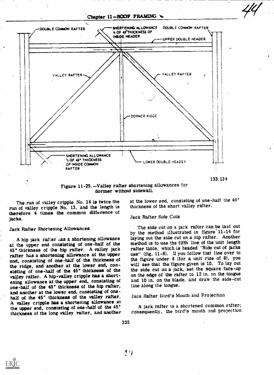
Chapter 11 ROOF FRAMING No,
DOuSLE COmmON RAFTER SHORTENING ALLOWANCE DOUBLE COMMON RAFTER
-
7iliur Nr ur
-
UPPER DOUBL EADER
VALLEY RAFTER VALLEY RAFTER
COMERIDGE
SH3RTENING ALLOWANCE"la OF 43. THICKNESSCIF ihouriF rrurunm \-- LOWER DOUBLE HEADER
RAFTER
Figure 11-25.Valley rafter shortening allowances fordormer without sidewall.
The run of valley cripple No. 14 is twice therun of valley cripple No. 13, and the length istherefore 4 times the common difference ofjacks.
Jack Rafter Shortening Allowances
A hip jack rafter ,ias a shortening allowanceat the upper end consisting of one-half of the450 thickness of the hip rafter. A valley jackrafter has a shortening allowance at the upperend, consisting of one-half of the thickness ofthe ridge, and another at the lower end, con-sisting of one-half of the 450 thickness of thevalley rafter. A hip-valley cripple ,has a short-ening allowance at the upper end, consisting ofone-half of the 45° thickness of the hip rafter,and another at the lower end, consisting of one-half of the 45* thickness of the valley rafter.A valley cripple has a shortening allowance atthe upper end, consisting of one-half of the 450thickness of the long valley rafter, and another
335
133.134
at the lower end, consisting of one-half the 450thickness of the short valley'rafter.
Jack Rafter Side Cuts
The side cut on a jack rafter can be laid outby the method illustrated in figure-11-14 forlaying out the side cut on a hip rafter. Anothermethod is to use the fifth line of the unit lengthrafter table, which is headed "Side cut of jacksuse" (fig. 11-8). If you follow that line over tothe figure under 8 (for a unit rise of 8), youwill see that the figure given is 10. To lay outthe side cut on a jack, set the square face-upon the edge of the rafter to 12 in. on the tongueand 10 in. on the blade, and draw the side-cutline along the tongue.
Jack Rafter Bird's Mouth and Projection
A jack rafter is a shortened common rafter;consequently, the bird's mouth and projection

BUILDER. 3 & 2
45.458Figure 11 -26. Method of framing gable
dormer with sidewalls.
on a jack rafter are laid out just as they areon a common ra:ter.
RIDGE LAYOUT
Laying out the ridge for a gable roof pre-sents no particular problem, since the linelength of the ridge is equal to the length of thebuilding. The actual length would include anyoverhang. For a hip main roof, however, theridge layout requires a certain amount ofcalculation.
As previously mentioned, in an equal-pitchhip roof the line length of the ridge amountsto the length of the building minus twice thetotal run of a main roof common rafter. TheACTUAL length, however, depends upon the
336
way in which the hip rafters are framed to theridge.
As inilicated in figure 11-32, the line lengthends of the ridge are at the points where theridge center line and the hip rafter center linescross. In figure 11-32 th hip rafter is framedagainst the ridge; in this uiethod of framing theactual, length of the ridge eiceeds the linelength, at each end, by one-half of the thicknessof the ridge, plus one-half of the 45'° thicknessof the hip rafter. In figure 11-32 the hip rafteris framed aetween the common rafters; in thismethod of framing the actual length of the ridgeexceeds the line length, at each end, by one-half of .the thickness of a common rafter.
Figure 11-33 shows that the length of theridge for an equal-span addition is equal to thelength of the addition rafter plate, plus one-halfthe span of the building, minus the shorteningallowance at the main roof ridge; the shorten-ing allowance amounts to one-half of the thick-ness of the main roof ridge. Figure 11-33shows that the length of the ridge for anunequal-span addition varies with the method offraming the ridge. If the addition ridge is sus-pended from the main roof ridge; the length isequal to the letigth of the addition rafter plateplus one-half the span of the building. If theaddition ridge is framed by the long-and-shortvalley rafter method, the length is equal to Omlength of the addition rafter plate, plus one-halfof the span of the addition, minus a shorteningallowance consisting of one-half of the 45°thickness of the long valley rafter. If the addi-tion ridge is framed to a double header set be-tween a couple of double main roof commonrafters, the length of the ridge is equal to thelength of the addition side-wall rafter plate,plus one-half the span of the addition, minus ashortening allowance consisting of one-half thethickness of the inside member of the doubleheader.
Figure 11-34 shows that the length of theridge on a dormer without side walls is equalto one-half of the span of the dormer, less ashortening allowance consisting of one-half thethickness of the inside member of the upperdouble header. Figure 11-34 shows that thelength of the ridge on a dormer with side wallsamounts to the length of the dormer rafterplate, plus one-half the span of the dormer,minus a shortening allowance consisting ofone-hall the thickness of the inside member ofthe upper double header.

Chapter 11 ROOF FRAMING
OUBLE MAIN-ROOFCOMMON RAFTER
SHORTENING ALLOWANCEh OF 45° THICKNESS OF
INSIDE MEMBER OP UPPERDOUBLE HEADER
DOUBLEHEADER
DOUBLE MAINROCIFCOMMON RAFTER
DORMER RIDGE
NORTENING ALLOWANCE s.or45 THICKNESS OF OUTSIDE MEMBER
OF DOUBLE MAIN-ROOF COMMONRAFTER. PLUS WHOLE 450 THICKNESS
OF INSIDE +MEMBER.
133.135
Figure 11-27 Valley rafter shorten ng allowances fox- dormer with sidewall.
SHED ROOF FRAMING
As previously mentioned, a SHED or SINGLE -PITCH roof is essentially one-half of a gableor double-pitch roof. Like the full-length raft-ers in a gable roof, the full-length rafters in ashed roof are COMMON rafters. Note, how-ever, that as shown in figure 11-35, the totalrun of a shed roof common rafter is equal to
337
the span of the building MINUS THE WIDTHOF THE RAFTER PLATE ON THE HIGHERRAFTER-END WALL. Note also, that the runof the projection on the higher wall is meas-ured from the INNER EDGE of the rafter plate.To this most be adcied the width of the ,plate andthe length of the overhang at the top. MIC-roofcommon rafters are 'aid out like gable-roofcommon rafters. A ed-roof common rafter

.77N,
BUILDER 3 & 2
F-ire 1 Types of ack rafters.
45,46011-29.Valley crtpple lack andhIp-valley cripple jacks,
338
45.459
has two bird's mouths, but they are laid outjust like the bird's mouth on a gable-roof com-mon rafter.
Figure 11-35 also shows that the height ofthe higher rafter-end wall, must exceed theheight of the lower by an amount equal to thetotal rise of a common rafter.
Figure 11-36 shows a method of framing ashed dormer. There are 3 layout problems tobe solved here, as follows: (1) determining thetotal run of a 'dormer rafter, (2) determiningthe angle of cut on the inboard endi of thedormer rafters. and (3) determining the lengthsof the dormer side-wall studs.
To determine the total run of a dorTerrafter you divide the height of the dQrmer endwall, in inches, by the difference between theunit rise of the dormer roof -and the unit riseof the main roof. Take the dormer shown infigure 11-37. for example. The height of the

r 11ROOF
133.136Figure 11 -30. Hip lack framing diagram.
dormer end-wall is 9 ft, or 108 in. The unitrise of the main roof is 8; the unit rise of thedormer roof is 2 1/2; the difference betweenthem is 5 1/2. The total run of a dormerrafter is therefore 108 divided by 5 1/2,19.63 ft. Knowing the total run and the unitrise, you can figure the length of a dormerrafter by any of the methods already described.
As indicated in figure 1147 the inboardends of the dormer rafters must be cut to fitthe slope of the main roof. To get the angle ofthis cut, set the square on the rafter to the cutof the main roof, as shown in the third view offigure 11-37; measure off the unit size of thedormer roof from the heel of the equare along
339
133.137Figure 11-31. Jack rafter framing diagram.
the tongue as indicated; make a mark at thispoint; and draw the cut-off line through thismark fro= the 12-in. mark.
You figure the lengths of the side-wall studson a shed dormer as follows: in the roof shownin figure 11-37, a dormer rafter raises 2 1/2units for every 12 units of run, and a main roofcommon rafter rises 8 units for every 12 unitsof run. If the studs were spaced 12 in, O.C.,the length of the shortest stud (which is alsothe COMMON DIFFERENCE of studs) wouldbe the difference between 8 and 2 1/2 in., or5 1/2 in. This being the case, if the stud spac -fug is 16 in., the length of the shortest stud isthe value of x in the proportional equation12:5 1/2::16:x, or 7 5/16 in. The shortest stud,then, will be 7 5/16 in. long; the next stud willbe 2(7 5/16)in. long, and so on. To get thelower-end cut-off angle for studs you set thesquare on the stud to the cut of the main roof:to get the upper-end cut-off angle you set it tothe cut of the dormer roof.
RAFTER LOCATION LAYOUT
Rafter locations are laid out on plates,ridge and other rafters with the same lines andX's used to lay out stud and joist locations.

BUILDER 3 ?a 2
5T'..1,-.7".
F ;
...E EN37o OF PPINEt
AC-L,AL LENGTH OF RtGE
n CF THiOt:NESS OF:CIAVAON Qt. F E LINE LE r*".; M OF rt!DGE
ACTA. LENGTH OF 4IOQE
Figure 11-32, Line and actual lengths of hip roof ridge.
Fr a gaLle roof the rafter locations are laidout on the rafter plates first, and the locatirmsare then transferred to the ridge by matchingthe ridge against a rafter plate.
The rafter-plate locations of the ridge-endcommon rafters in an equal-pitch hip roofmeasure one-half of the span (or the run of amain-roof common rafter) away from the build-ing corners. These locations, plus the rafter-plate locations of the rafters lying between the
dge-end common rafters, can be transferredto the ridge by matching the ridge against therafter plates.
The locations ot.;.addition ridge arid valleyrafters can be determined as indicated in fig-ure 11-38. In an equalbspan situation (illus-trated in parts 1 and 2, fig. 11-38) the valleyrafter locations on the main roof ridge liealongside the addition ridge location. In part 1of figure 11-38 the distance between the end ofthe main roof ridge and the addition ridge
340
133.138
location is equal to din.ance A plus distance 5,thstance B being one-half the span of the addi-tion. In part 2 of figure 11-38 the distancebetween the line length end of the main roofridge and the addition ridge location is thesame as distance A. In both cases the linelength of the addition ridge is equal to one-halfthe span of the addition plus the length of theaddition side-wall rafter plate.
Part 3 of figure 11-38 shows an unequal-span situation, If framing is by the long-and-short valley rafter method, the distance fromthe end of the main roof ridge to the upperend of the longer valley rafter Is equal to dis-tance A plus distance B, distance B being one-half of the span of the main roof. The locationof the inboard end of the shorter valley rafteron the longer valley rafter can be determinedas follows: first cakulate the unit length ofthe longer valley=rafter, or obtain it from theunit-length rafter tables. Let us suppose that

Chapter 1 ROOF FRAMING
113.139Fiie 1 1 -33 --Lengths of addition ridge.
the common-rafter unit rise is 8; i.n that casethe unit length of a valley rafter is 18,76.
The total run of the lonr. valley ratter be-tween the point where the onorter rliter tiesin and the rafter plate is kthe hypotenuse of aright triangle with other sides each equal toone-half of the span of the addition.. Supposethe addition is 20 ft wide; then the total run inquestion is the square root ol 102 + 102), or14.14 ft.
You know that the valley rafter is 18.76units. long for every 16.97 units of run. Thelengtn of rafter for 14.14 a of run must there-fore be the val.ie of x in the proportional equa-tion 16.97:18.76::14.14:x, or 15.63 ft. The lo-cation mark for the inboard end of the shortervalley rafter on the longer valley rafter, then,wilt be 15.63 ft, or 15 ft 7 9:16 in., from theheel plumb cut line on the longer valley rafter.The lem.rth of the addition ridge will be equal
341
133,140Figure 11-34. Lengths of dormer ridge.
to one-half the span of the addition, plus thelength of the addition side-wall rafteT plate.minus a shortening allowance equal to one-halfof the 45° thickness of the longer valley rafter.
If framing is by the suspended-ridge method.the distance between the suspension point onthe main roof ridge and the end of the mainroof ridge is equal_to..distance A plus dis-tance C; distance C is one-half of the span ofthe addition. The distance between the pointwhere the inboard ends of the valley raftersi.both short in this method of framing) tie intothe addition ridge and the out-board end of theridge is equal to one-half the span of the addi-tion plus the length of the addition side-wallrafier plate. The length of the addition ridgeis equal to one-half of the span of the main roof

BUILDER 3 & 2
TOTAL RISE OFCOWAION RAFTER -
70TAL
PROJEC-
TCTAL RUN OF CaMMQN RAFTER
4;11 r e 11 -35. --Shed roof framing.
133.142zu re 11 -36, Method of framing a
shed dormer.
342
133,141
plus the length of the addition side wall rafterplate.
COLLAR TIE
Gable or double-pitch roof rafters are oftenreinforced by horizontal members called collarties (fig. 11-39). In a finished attic tire tiesmay also function as ceiling joists.
To find the lipe length of a collar tie dividethe amount of drop of the tie in inches by theunit of rise of the common rafter. This willequal one-half the length of the tie in feet.Double the result for actual length. The for-mula is: Drop in inches x 2 over unit of rise,equals the length in feet.
The length of the collar tie depends onwhether the drop is measured to the top edgeor bottom edge of the collar tie (fig. 11-39).The tie must fit the slope of the roof, To ob-tain this angle, use the framing square. Hold

Chapter 11 --14
N.
-`1. .1 R
N.
1 CiFt mre iIT7. Shed &ruler franiing
culations,
Unit of run And unit of riserafter. ind :ut !ni unit
F THUSSE
Much modern roof fram ng is done -withROOF TRUSSES like the one shown in figure11-41. The principal parts of A truss are theUPPEtt CHORD (consisting of the rafters). theLOWER CHORD ;corresponding to ajoistt, And various diagonal and or yertwal4iracing and connecting Metnbers ,Yhich areknown collectively as the WED MEMEWHS.
The truss shown in figure 11-41 is ilinedat the corners with plywood GUSSrn"S, Othermethods of ,f,rner joining are by metal gussetsor by various types of nottthed to1ntS4 reinforced
.4 4.1
FRAMINt;
_
135.1441.1 . -Inte1tsect4( cicc and
locattor, layout.
oh h. ,nst ruct fonLISLi.i11% :1 :liotai
-mat --In on I SC'S
A.41 cc, l'1ON
Ho.7! !!-.111-1 Iry :.11:111d be ,i,me froln soanoictkltJ) p1.1.11k111, le:i6 than 4 it below the
')t t!te main root riclire. The usual type of rrytt:-;4-1!folt1 constsf:; diaLonally -braced 2-le.4dhr-,1-...;es, spaced _ihout 10 ft apart and extendine,the full lene.th ot the ruit2,-e
if the iludrillw. has .in dd I f .111. as muvi) aspossible ot th,- rn,tn root ts trtmed hetore theatidttlon 1-3 n11111; IS start4-t. ipIvs and 1.1L-K
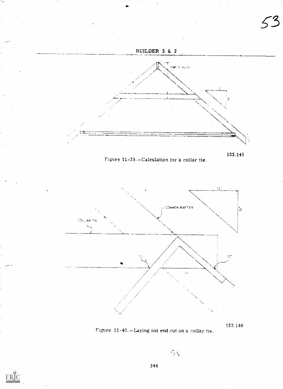
T
BUILDER 3 & 2
,
Figure 11-39. --Calculation for a collar tie.133.145
N.,
133 146Fig-ure 11-40.Laying out end cut on a collar tie.
344

11 FRAINalNo
45.438Figure 11-41. --;Typical lightweight roof truss.
rafters are usually left out until 4ter the head-ers, hip rafters, valley rafters, and ridges towhich they will be 'framed have been installed.
For a gable roof the two pairs of gable-endrafters and the ridge are usually erected first.Two men, one at each end of the scaffold, holdthe ridge in position, while a third man sets thegable-end rafters in place and toenails them atthe rafter plate with 8-penny nails, one to eachside of a rafter. Each man on the scaffold theneiid-nails the ridge to one pf his rafters withtwo 10-penny nails, driven through the ridgeinto the end of the rafter; and toenails the otherrafter to the ridge and to the first rafter withtwo 10-penny nails, one on each side of therafter. Temporary braces like those for awall should be set up at the ridge ends to holdthe rafters approximately plumb, after whichthe rafters between the end-rafters should beerected. The braces should then be released,and the pair of rafters at one end should beplumbed with a plumb line, fastened to a stickextended from the end of the ridge. The bracesshould then be zeset, and they should beleft inplace until enough sheathing has been installedto hold the rafters plumb. Collar ties, if any,are nailed to common rafters with 8-pennynails, 2 to each end of a tie. Ceiling-joist endsare nailed to adjacent rafters with 10-pennynails, 2 to each end.
On a hip roof the ridge-end common raftersand ridges are erected first, in about the samemanner as for a gable roof, and the intermedi-ate common rafters are then filled in. Afterthat, the rid4e-end comition rafters extending
345
rem the ridge ends to the mid-points on theend walla are erected. The hip rafters and,hipjacks are installed next. The common raftersin a hip roof do not require plumbing; if the hiprafters are correctly cut, installing the hiprafters will bring the common rafters plumb.Hip rafters areloanailed to plate corners with16-penny nails; 2 to each side. Hip jacks kretoenailed to hip rafters with 10-penny nails,3 to each jack.
For an addition or-dormer the valley raftersare usually erected first. Valley rafters aretoenailed to plates 'nth 16-penny nails, 2 toeach,side, and to3 ridge pieces and headers withthree 104enny nails. Ridges' and ridge-endcommon rafters are erected next, other addi-tion'common rafter next, and valley and crip-ple jacks last. A -ialley jack should be held inposition for nailing s shown in figure 11-42.When properly nailed, the end of a straightedgelaid along the top edge of the jack should con-tact the center line of the valley rafter asshown.
133 147Figure 11-42. Correct position for nailing
a valley sack rafter,

BUILD
)cr:" NFTUING
l'he lower liv of rof cov,?ring is calledhe Pr:OF SHEATHING: the ,:pper layer is'alled :he ROO7 CONIFRlYC r he ROOTIN(17-,
ihe ...;41,.,,heathui,4 and:--ng. sirtic,urill ,lernent and
The roof ,_.iov--rin.4- or ."1(1.7-_; ext.erior
1:.:heathing Ar/-! sub-either l'crizontally or
niz7 t)e- either417,D eoin Ia i -,.th 'ity.lces between
-lurses: ,-)r OPEN sheathing ;laid .vith spaces,,,t-ween ,.,..-)urses'. Open sheathing is used for
'Inlv when :ing is tr3Clos2d sheathing
-n. .:1 1,i:flay consist-_-)arls hut ma:: be dressed-
)r)en .neathing usually
R 3 & 2
consists of 1 x 3 or 1 x 4 strips. with spacingO.C. equal to the specified exposure of shinglesTO THE WEATHER. An I8-in. shingle whichis lapped 12 in. by the shingle above it is saidto be laid 6 in. to the weather.
Sheathing should be nailed with tWo 3-pennynails to each rafter crossing*. End-joint re-quirements are the same as those previouslydescribed for wall sheathing. The sheathingends should be sawed flush with the outtr faceof the end-wall, sheathing, unless a projectionof the roof sheathing over the 1nd-wal1s is calledfor. If such a projection is needed, projectingSiteathing boards rhust be long enough to spanat least 3 rafter spaces.
Plywood, usually in 8-ft x 4-ft sheets, laidhorizontally, is frequently used for roof sheath-ing. Nailing requirements are the same asthose previously described for 8-ft x 4-ft sheetsof plywood wall sheathing.

I
SPECIAL CON TRUCTION BATTALION TRAINING
BUILUERS SCHOOL
15O1 tight Frame Construction I
3-MAY 1975
c

CO1RSL E:0;TH;
TArc:iT AT:
c.
;-.EMENTS PER CLASS: 1 instructor per 16students
A ILI; P\(;1'
!TM . ql VitA INJzArqi +ei1104:11()N
U S.
Ccnstruction Training CenterPort Hueneme, Cali ornia 93043
-
- 8
40DFL 4ANAGER: Naval Cons truLt ion Training CenterP.)rt Hueneme, California 93043
('H f Naval Techlical Training.
"..AAA:=E!!ENT ALTHORITY: School at which taught.
HXENTATLON DATE: When approved by the Chief ofNaval Technical_ Training
iii

TABLE OF minim
(1)1'Y ) AiTRHVED UTTER
REctRU or CHANCV PKE
TITLE PAGE
HOW TO USE INSTRUCTOR GUIDE
COURSE DATA PAGE
OUTLINE OF INSTRUCTION
TRAINIM OBJECTIVES
ANNEX I TEXTS
ANNEX LI REFERENCES
ANNEX III TOOLS, EQUIPMENT AND MATERIALS
ANNEX IV TRAINING AJOS
ANNEX V TRAINING AIDS EQUIPMENT
ANNEX VI MASTER SCHEDULE
PACE
iv

COURSE DATA PAGE
,COURSE MISSION: To train select builders and builder strikers in theknowledge and skill factors defined by the personnel readiness capabilityprogram, skill level 150.1.
PE3SONNEL AND RATING ELIGIBLE: E-2 thru E-4
OBLIGATED SERVICE: NONE
NEC L'RNED: N/A.
PHY5ICA1 REQUIREMENTS: NONE
SiURLY =ARANCE REQUIRED: NONE
PREREQUISITE TRAINING AND/OR BASIC BATTERY TEST SCORE REQUIRED: NONE
REL1TED TR:.INING: NONE
F( -UP TRAINING: NONE
E"ALUATION: Performance will be evaluated on a go/no go basis.

OUTLINE OF INSTRUCTION
TOPIC Unit 1,1 CLASS FRACT TOTAL PAGE
INTRODUCTION
1.1.1, Orientation1.1.2 Safety
1.5 1.5 3
Unit 1..
It Frame Structures
1.2.1 Sills and Girders 3 3. 6 3.1.2.2 Floor Joists and Solid Br dging 1 4 5 31.2 Subfloors and Wall Plates 3 5 41. 2A Wall Members 2 15 17 41.2.5 Ceiling and Roof Construction 3 4 7 4
Gable End Studs 1 1 3. 41.2,7 Cours? Summarization 1 4 5 4
35 48
Tot31 Periods Classroom:al Per ods Practical:al Hours Per Course:
Lich per
15
5
50
of instruction represents 60 minues actual instruction.

OUTLINE OF TRAINING OBJECTIVES
Unit 1.1 INFORMATION Contact Hours: 2
Termleat (hj r t ive: Upon completion ol this unit the student will haverviwricd t Bulkier Scitmli and received the school. erlenkatlen and safetyprocedures required te complete the assigned irse el Instrurilon am a
SCBT student.
Topic 1.1.1 ORIENTATION Contact Hours: 1.5
.hLLng Objective: Upon comple .on of this topic the student will havercortec, for the course and answered questions pretaining to key, points)n te rgan1zation, mission and regulations_of NAVCONSTRACEN.
Toric 1. 1..2 SAFETY Contact Hours: 0.5
7:nig Objective: Upon co&pletion Df this topic the student will be:e report accidents or fire and state the safety practices that willorcod in.the school. ,
LIGHT FRAME CONSTRUCTION ½ Contact Hours: 48
,Ai ObjectiVe: Upon completion of the unit the student will havemet ,W the requirements of the,Personnel Readiness Capability Program, skilllevui 150.1 - Light Frame Construction I involving substructure framingwall framing and roof framing. 'The light frame structures are to bee-ec-Pd by following the procedures and meeting the specifications stated
ioh sheet.
. 2.1 SILLS AND GIRDERS Contact Hours: 6
Ena2 ng Objective:' tJpon completion of this, topic the student-will benble ',.() lay out, cut and install sills and girders following proceduresin w:-.)rdince with job sheets SCBT 150.1 SU JS 1.7.1.1, "Installing SillPl_aces," lnd SCBT 150.1 BU JS "Placing and Posting Girders".The iAistalled sill plates and:girders will be within job sheet specifi-catioes.
Topis. 1 2.2 FLOOR JOISTS AND SOLID gRIDGING Contact urs:
Enabling Objective: Upon completion of this topic the student will be
.11-)1,-: to lay out', cut and install floor joists and solid bridging followingprocedures in job sheet SCBT 150.1 BU JS 1.2.2.1, "Floor Joists andBridging (solid) Layout and Erection". The installed.floorpframing will
ne within job sheet specifications.
3

ic 1.2.3. SUBFLOORS AND WALL PLATES Contact Hours:
Enabling Objectives: Upon completion of this.topic the student will beable to lay out, cut, and install subflooring and wall plates followingprocedures in job sheet SOT 150.1 BU JS 1.2.3.1. "Inptalling Subfloors"and SCBT 150.1 BU JS 1.2.3.2, "Laying Out Sole and TOO Plates". Theinstalled subflooring and sole plates will be within job sheet specifi-cations.
Topic WALL MEMBERS Contact Hours: 17
Fnabling Objectives: Upon coMpletion of this topic\ the student will belole ;o 1.1y out, cut and install sttias, fire blocks', headers, sills andbracing fr)llowing procedures and meeting the specifications outlined injob sheets SCBT 150.1 BU JS 1.1.4.1, "Erecting and Securing Wall Sections,SCBT 150.1 BU JS 1.1.4.2, "Installing Fire Blocks and Diagonal Bracing,"ard SCBT 150.1 Btl JS 1.2.4.3. "Installing Trimmer Studs, Cripple StudsSills and Pzaders".
Topic 1.2.5 CEILING JOISTS AND ROOF CONSTRUCTION Contact Hours:
Enlbling Objective: Upon completion of this topic the student will beile to la: out, cut and install ceiling joists and rafters followingprocedures in accordance with job sheets SCBT 150.1 BU JS 1.1.5.1."Cutting and Installing Ceiling Joists", SCSI' 150.1 SU JS 1.1.5.2.,"Raising Roof Frames", and SCBT 150.1 BU JS 1.2.5.3., "Laying Out CommonRafters". The installed ceiling joists and rafters will be within jobsheet specifi- tions.
Topic 1.2.6 GABLE END STUDS Contact Hours: 3
Enah:ing Ob ective: Upon completion of this topic the student will beable to lay out, cut and install gable end studs following procedures inaccordance with job sheet SCBT 150.1 BU JS 1.2:6.1, "Laying Out, Cuttingand Installing Gable End Studs The installed studs will be within jobshe t specifications.
TopiL 1.2.7 COURSE SUMMARIZATION Contact Hours: 5
bling Objective:* Upon completion of this topic the student will havereinforced his ability to identify by naming all the framing members inaccordance with the texts as the members are pointed out by the instructor.ihe student will also have reviewed the methods used in the erection of thelight frame structure as a structure is torn down. The dismantled framing7embers will be clear of all nails and will be neatly stacked.
4

ANNEX I
TEXTS
1. Builder 3 61 2, NAVPERS 10648F
2. Framing, sheathing and Insulation, De: ar Publishing Company

at
ANNEX II
RENCFS
Fundamentals of Carpentry, American Technical Society.
Practical Carpentry GoodheartWilcox Company.

ANNEX 111
sAx)L-, HIUIPMLNI A 1) MATERIAL
QUANT. PRICENSN/MFG. NO. ITEM
5110-00-186-81 1 alisel, Wood 1 1/2" 1 ea. 9.60
5110-00293-3435 Saw, Cross cut 8 points 1 ea. 3.35
51 0-00-'93-0665 Bar, Wrecking 3/4 X 30" 1 ea. 1.95
5120-00 49-8083 Wrench, Adjustable 1 1/8 X 10" 1 ea. 3.20
5120-00-892-5485 Hammer, Carpenter 16 oz. 1 ea. 3.60
5130-00_ 93-3456 Drill ortable electric 3/8" dia. 1 ea. 45.50
)0 8-1327 Drill Bit, 5/8" dia. (12 to a pkg.) 1 pkg. 4.20
520-00-078-8948 Square, Combination 12 in. 1 ea. 7.10
5210-00-221-2050 Square, Framing 1 ea. 4.40
52i-00--2i3-9793 Chalk Line and RegL- 1 ea. .83
5210-00-278-0645 Square, Sliding-T-Bevel 1 ea. 1.24
5210-00-293-,3505 Measuring Tape, 10 ft. 1 ea. .94
.210-00-9 6-5430 Level, hand, carpenter 28 in. A. ea. 4.45
Saw, Circular, portable, electri.7 inch blade 1 ea. 60.00
EQIPMNT:
54-7 )0-51-:i-9487 Ladder Step 8 Ft. 1 ea. 17.40
il5J-01-665-7972 Extension cord, single outlet 1 ea 1.75
0-272-9436 Keel blue,soft (doz) 1 bx. .65
8415- '-205-3895 Apron, nail, carpenter 1 ea. 2.50
MATERIALS;
Saw horse
2 x 4's
6

TGOL..s_LEZziaLIES_DAMATERIAL n 'd)
1 x 6's
x 4's
4 0 X 8' 0 Plywond
5315-00-010 '659 Nails 8d com. 50# box
Nails 8d duplex
5315-00-010-4663 Nai4.s,16d com 50# box
I bx. 13.50
1 bx. 13.50

Transparencies (cont'd)
16. NP-311013.3T -12 Framed Openini (window)
17. 11CS -11013.101T -2 Platform Western Frame Construction
11CS -10321.101T -2 Rafter Cuts
19. 11CS -10321.101T -1 Rafter Measurements
20. 11cS-7400064-T Common Rafter Layout.
Marts
1. Illustrating sub-structure of a frame structure.
2. Illustrating frame structure.
Sample
1. 2 x 4
2. 2 x 6
3. 4 x 4
4. 4 x 6
5. 8d box nail
6. 16d box nail
Model
1. Platform Frame Building
Locally Prepared Mat rials
1. Floor Plan
Job Sheets
1. SCBT 150.1 SU JS 1.2.1.1 Installing Sill Plates
2. SCBT 150,1 BP IS 1.2.1.2 Placing and Posting Girders
. San 150.1 BU IS 1.2.2.1 Floor Joists and Bridging (solid)Layout and Erection
4. SCBT 150.1 EU JS 1.2.3.1 Installing Subfloor
S. SCBT 150.1 BU JS 1.2.3.2 Laying Out Sole and Top Plates.
6. SOT 150.1 EU JS 1.2.4.1 Erecting and Securing Wall
A-IV-2

ANNZX Iv
TRAINING AIDS
Films:
1. HOW-016 How to use Measuring Tools.
2. HOW-018 How to use Saws.
. HOW-014 How to use Hammers.
4. HOW-015 How to use Hand Boring Tools.
5. MN-6719B Building Technique - Framing Floor Joists and Wall.
6. GIF-001 The Gift of Life.
7. MN-6719-C Building Technique - Framing, Rafter Principles andCommon Rafter.
Transparencies:
1. 1ICS-7400055-T Sill
2. 11CS-7400056-T Sill and Girder
3. IICS-7400057-T Framing Joists and Girder
4. 1ICS-10321.101T-5 Floor Joists Layout
5. lICS-7400058-T Wood Bridging
6. 11CS-10321.101T-3 Rough Opening for Windows.
11CS-10321.101T-4 Rough Opening for Doors
11CS-7400059-T Subfloor
11CS- 400060-T Subfloor and Underlay
311013.3T-8 Sole Plate
Ll. 11' 7400065-T Corner Balloon and Platform Framing
12. NP-311013.3T-13 Platform Framing
13. NP-311013.3T-14 Platform Frai.
i. 11CS-7400063-T Wall Backing
NP-311013.3T-9 Bracing in Framing
A-IV-1

gob Sheets (coned)
7. SCBT 150.1 SU JS 1.2.4.2 installing Firs Blocks and Diagonal Bracing.
SUIT 150.1 SU JS 1.2.4 1 Installing Trimmer StudsoCrippla Studs Sills.find Headers.
9. SCIAT 150.1 SU JS L.2.5.1 Cutting and Installing Coiling Joists.
10. SCBT 150.1 BU JS 1.2.5.2 Raising -Roof Frames
11. SOT 150.1 BU JS 1.2.5 3 Laying Out Common Rafters.
12. SCBT 150.1 BU JS 1.2.6.1 Laying Out, Cutting and Installing GableEnd Studs.
ANNMX V
TRAIt4INC AIDS 111DIPMV/IT
1. 16m Movie Projector
2. Overhead Projector.

ANNEX VI
FIRST
TOPIC NO. TYPE PERTOD TITLE RATIO
FIRST DAY
1.1.1 C 1 Orientation 16/12
1.1.2 C 2.5 Safety 16/11.2.1 C 3 Sills and Girders 16/1
4
6 16/17
ND DAY
1.2.1 8 Sills and Girders 16/11.2.2 9 Flooi Joists and Solid Bridging 16/1
10 16/111
12
131.2.3 C 14 Sub floors and Wall Plates 16/1
THIRD DAY
1. .3 C 15 Sub floors and Wall Plates 16/116 16/117
18.4 C 19 Wall Members 16/1
2021 16/1
FOUR1H DAY
1.2.4 22 Wall Members 16/123
24
25
26
27
28
FIFTH DAY
1.2.4 P 29 Wall Members 16/130
A -VI -1

SECOND WENN
TYPE PERIOD TITLE RATIOTOPIC NO.
FIRST DAY
1.2.4. 1 Wall Members 16/12
3
4
5
1.2.5. 6 Ceiling Joists and Roof Construction 16/17
SECOND DAY
1.2.5. 8 Ceiling Joists and Roof Construction 16/19 16/1
10
1112
1.2.6 13 Gable End Studs 16/114 16/1
THIRD DAY
1.2.6 P 15 Gable End Studs 16/11.2.7 C 16 Course Summarization 16/1
P 17 16/118
19

MODIFICATIONS
-7-14047 JJ4 2 / of this publication has (have) been deleted in
adapting this material for inclusion in the "Trial Implgmentation of a
Model System to Provide Military Curriculum Materials for Use in Vocational
and Technical Education." Deleted material involves extensive use of
military forms, procedures, systems etc. and was not considered appropriate
for use in vocational and technical education.

SCBT-100 190-11U-IG-1.1.2
RAVAL CONSTRUCTION TRAINING CENTERPORT HUENEME, CALIFORNIA-93043
SPECIAL CONSTRUCTION BATTALION TRAINING COURSE (SCBT) 100 - 190
Classification: Unclassified
Topic: Safety
Average Tine: 0.5 Periods (Class)
Instructional Materials:
A. Texts: None.
B. References.
Terminal Objective: Upon completion of this unit the
student will have reported to Builder School, received
the school orientation and safety procedures required tocomplete the assigned course of instruction as a SCBT
student.
Enabling Objectives: Upon completion of this topic thestudent will be able to report accidents or fire, and statethe safety practices that will be enforced in the school:
NAVCONSTRgNINST. 5400.4, (current series) Criterion Test,: The student will answer orally specific
"Organization Manual of NAVCONSTRACEN." question pertaining to the method of reporting andfighting fires as established by NAVCONSTRACEN and CBCregucations, and will conform to the safety policies for
the duration of his assignment to Builder School."Safety Practices for Shore Activities,"XACMAT P-5100, (Jan 1973).
C. Tools and Equipment: None.
D. Training Aids and Devices.
1'; Film.
a. GIF-001, "The Gift of Life," (18 min.)
E. raining Aids Equipment.
1. 16mm Movie Projector,
Homework: None.
(1 of 4)

OUTLINE OF INSTRUCTION
I. Introduction to the Lesson:
A. Establish contact.
I. Name:
2. Topic: Safety.
B. Establish readiness.
1. Purpose.
2. Assignment.
C. Establish effect.
I. Value.
a. Pass course.
b. Perform better on the job.
D. Overview.
SCBT-100 - 190-BU-1G-1.1.2INSTRUCTOR ACTIVITT STUDENT ACTIVITY
I.A. Introduce self and topic.
LB. Motivate student.
I.C. Bring out need and valueof material being preseuted.
I.D. State learning cjectives.
You will be able to answevorally specific 1. State infovmacion andquestions related to the methods of reporting materials necess,Ary to guideand fighting fires-as established by student.NAVCONSTRACEN and CBC regulations and conformto the safety practices that will be enforcedin this school.
Ask questions.
Take notes.

OUTLINE OF INSTRUCTION
II. :Isentation:
A. Safety.
1. Reporting accidents.
Class safety man.
h. Instructor.
SCIool director.
aid when appropriate.
2. Fire safety.
a Evacuation routes.
SCBT-100 190 -BU-IG-1.1.2 )
INSTIUJCTOR ACTIVITY STUDENT ACTIVITY
1.a. Pick safety mand andexplain job
Reporting fires.
FIghting fire.
(1) Location of extinguishers.
Field safety. A.1. Introduce film.
Show film: GIF-001 "The Gift of Life. ft a. Discuss kr; pointsto look for.
h. Show fil
Discuss film highli s. 3.b. Lead discussion.
1. Ask questions.
2. Stress safet,
(3 of 4)
3.b. Participate indiscussion - askquestions as necessary.

OUTLINE OF INSTRUCTION
III. Application:
A. Discussion.
IV. Summary:
A. Safety.
Reporting accidents.
Fire safety.
Field safety.
V Test
A. Nont,.
(4 of 4)
//SCRT -100 - 190-BU -IG-1.1.2 (
INSTRUCTOR ACTIVITY STUDENT At:TIVITY
III.A. Questions to be III.A. Answer and asic
developed by the instructor. questions.

SCBT-150.1-BU G-1.2.1
NAVAL CONSTRUCTION TRAINING CENTERPORT RUENEME, CALIFORNIA 93043
SPECIAL CONSTRUCTION BATTALION TRAINING COURSE (SCBT) 150.1
Classification: Unclassified
Topic: Sills and Girders
Average Time: 3 Periods (ClasS)3 Periods (Pract)
Instructiona 4aterials:
A. Texts.
1. Bu lder 352, NAVPERS 1
C1iapter.10.
Framing, heathing and Jn!zulation,Delmar Publishing co., Units 1 4.
Referem:e.
1. Fundamentals of Carpentry Ameri,:an
Technical Society.
tools and Fquipment.
I. `1easuting tape.
squarf,.
Hand level.
5. Framing r,quare.
6. Hammer.
Terminal Objective: Upon completion of this course thestudent will have met all the requirements of personnelreadiness capability program, skill level 150.1 - LightFrame Construction I involving sill plate, post, girder,floor joist, bridging, sub-flooring, plate, ridge piece andgable end stud. The light frame structure is to be erectedby folloving procedures in accordance with job sheets andto within the requirements as stated on the job sheets.
Enabling Objectives: Upon completion of this topic thestudent will be able to lay out, cut and install sills andgirders following procedures in accordance with job sheetsSCBT-150.1-BU-JS-1.2.1.1, "Installing Sill Plates," andSCBT-150.1-BU-JS-1.2.1.2, "Placing and Posting Girders."ihe installed sill plates and girders will be within jobsheet specifications.
Criterion Tests: Given the proper tools, materials and lobsheets,'the student will be tested on his ability tocorrectly use and care for carpenter hand tools and portableelectric tools. He will perform all tasks as outlined inthe objectives and will meet all tolerances as stated in thejob sheets.
Homework: Read: Builder 3&2, NAVPERS 10648-F, Chapter 10and Framing, Sheating and Insu ation, Units 3 f* 4, pp,19 -
7. Chisel.
Portable electric circular saw.
Portable electric drill.
10. Drill bits.
11. Adjustable wrench.
12. Saw horses.
13. Nail apron.
D. Training Aids and 1Jevices.
1. Films.
HOW-016, "How to Use MeasuringTools, 12 min.
. HOW-018, "How to Use(12 min_
HOWr014, "How to Use Hammers,"(12 min.).
HOW-015 "How to Use Hand Boring Too16,(10 min.
c. MN-6719B, "Building Technique - FramiugFloor Joist and Wall," (25 min.).
Fransparencies.
a. 110S-7400055-T,
b. 110S-7400056-T, Sill and Girder.
(2 of 11)
SCBT-150.1-14U-IG-1.2.1

C. 11CS-7400056-T, Framing Joists and Girder.
3. Materials.
a. 2 x 4's, 2 x 6's, 4 x 4's and 4 x 6's.
4. Platform frame building (model).
Chart(s) illustrating sub-structuresframe building.
6. Samples of Materials.
a. 2 x 4.
b. 2 x 6.
o. 4 x 4.
4 x 6.
8d box nails.
6d box nails.
Locally prepared materi is.
Job sheets.
f a
SCBT-150.1-BU-JS-1.2.1.
(1) SCBT-150.1-8U-JS-1.2.1.1, "Installing Sill Plateq.
(2) SCBT-150.1-BU-JS-I. 2, "Placing and Posting Girders."
Training Aids Equipment.
1. 16mm movie projector.
2, ithrerhead projector.
(3 of 11)

OUTLINE OF INSTRUCTION
Introduction to the Lesson:
A. Establish contact.
1. Name:
2. Topic: Sills and Girders.
B. Establish readiness.
1. Purpose.
Sill is the member where the woodportion of the structure ties onto theconcrete foundation.
Girder is the member that supportsfloor joists.
2. Assignmenr.
Read; (1) Builder 3&2, Chapter 10,(2) Framing, Sheathing and Insulation,Unit 3 and 4.
Establish effect.
Value.
Pass course.
Perform betzer on the job.
advanced.
Be a better build
(4 of 11)
FY,SCBT -150.1 -BU -IG -l.2.1
INSTRUCTOR ACTIVITY STUDENT ACTIVITY
A.1. Introduce self.
A.2. Introduce topic.
B.1. Motivate the student bydefining the functions of thesemembers. Accuracy should bestressed saying that if the sillplates are placed inaccuratelythe building that is erected init will be inaccurate.
C.1. Bring out need and value ofmaterial being presented state
learning objectives.
a. Upon completion of this topic,you will be able to layout, cutand install sills end girders.You will also be able to correctlyuse carpenter hand tools and port-able electric power tools.

OUTLINE OF INSTRUCTION
Overview.
1. Job sheets.
a. Follow instructors demonstration oil th,!job sheet.
. Job sheets are to help you in the fieldexercises. Refer to them when in doubt.
2. Safety precautions in using:
R. Electric portahle circular saw.
b. 'Electric portable drill.
c. Hand say.
3. Ask questions any time raise your hand an0be recognized before asking.
II. Start'presentation:
A. Introduce job sheets.
SCIIT -150.1 -13U -IG-1.2.1
INSTRUCTOR ACTTVITY STUDENT ACTIVITY
II.A. nand out job sheets. II.A. Job sheets areto be returned at the
SCTIT-150.1.-BIT-JS-1.1.1.1, "Installing Sill completion of thisPlates. topic. However, if
you wish to keep aSCBT-l50. BU-JS-1.1.1.2, "Placing and Posting copy for your own, askGirders. 't the instructor for
them.Tools and Equipment.
(5 of 11)

OUTLINE OF INSTRUCTION
1. FiLm
a. Introduce film.
b. Discuss key points.
c. Show film.
d. Discuss highlightb.
(1) HOW-0160 "How to Use MeasuringTools." (1) teed discussion.
(2) HOW-018, "How to Use Saws." (2) Ask 'questions.
(3) HOW-014, "How to Use Hammers."
SCRT-I O. (INSTiUCTOR ACTIVITY . STUDENT ACTIVITY
I.a. Introduce one film at'atime.
1.b. Discuss.key poipts priorto each showing of film.
I.d. -Discuss highlights after 1.4. FarticipateindiscusPion.showing of film.
(4) HOW-015, "How to Use Hand BoringTools."
2. Introduce tools and equipmeLt not in film. B.2. Show tools and equipment
a. Hand level.
b. Extehsion cord.
c. Portable electric circular saw.-40
d. Portable electric drill.
e. Adjustable wrench.
f. Saw horses.
Chalk line.(6 of 11)
as they are introduced.
9 S

OUTLINE OY INSTRUCTION
3. Materials.
'f a. 2 x 6'sV
b. 4 x 4's%
c. 4 'x 6's.
Sd
e. 16d duplex .nails.
f. 16d box nails.
C. Sills., r-'4
SCST-1 0.1-BU-IG-1.2.1tOSTRUCTOR ACTIVITY
B.3. Show samples of wood'pieces and nalls'to,reinforcepresentation.
/I.e., Give,* brief lecture onsills-and girder. To reinforce
1. Definiti6n - bearing members placed on lecture use:foundation walls.
Types.
a. Lapped.
b. Leminated.
c. Solid.
d. 'Box.
/ /Girders.
I. Definition bearing members that supportfloor Joists and smaller beams.
2. Types.
(7 of 11)
a. Nrodel on platform frsmabuilding.
b. Chart(s) illustratingsubzstrUctsires of a frame Vbuilding.
c. Transparencies.
(1) lICS-7400053-T.(2) 11CS-7400056-T.
STUMM/ ACTIVITY'
II.D. Give brief lecture on girders toreinforce'lecture)use:
a. Model ln pl form fireme.building
b. Chart(s) illustrating sub-structnresof frwe building
c. Transparency.
(1) lICS -74000 7-T.

-ourim OF iNSTRUeTION
a. Built up.
b. Said.
d..
3. Film.
a. Introduce film.
b. Discuss key points._
c. Show film.
(1) MN-671911,"Building Technique, FramingFlcior Joists and Wall."
d. Discuss filM. r
(1) Hi hliihts.
(2) Safety.
Steps of procedures.
1. Sill lay out technique.
Prepare first sill section.
b. Select straight 2 x 61.
c. Position 2 x 6 member.
d. Lay out for author bolt.
(8
SCHT450.1-BU-IG-1. 2.1INgTRUCT9R. ACTInTY SUMER ACTIVITY
N,D.3 .Give brief introduction tothe film, pointing out the keypointsIto look for in the filmand then show the film.
301. Lead discussion by asking 3.d. Participate in thand answering quelions on the discussion.film - stress safety.
II.E. Ta class out i hefield to demonstrate - tallstudents attention to job sheet
SCBT-150.3.-BU-JS-1.2 .1.1.
II.E. Follow procedurein the demonstrationon job sheet.
102

AnturenisTRUCTIoN
Lay out for sill length.
Sill preparatioi technique.
a; Place sill plate section on saw horses.
Use portable electric cirpflar saw tocut sill plate to lang0./ Stresssafety Ln thernsage 4f:this saw.
c: Use portable electric drill to drillreqtkired holes - stress the need of ahole 1/8" larger than anchor bolt size.
Sill plate installing technique.
'e
Place sill plate in *position, placea washer oneach bolt and hand tightenthe nuts. (
Girder lay/out and preparation technique.
Deteraine length'of
b. Select straight 4.x 6 and place it on,ftaw horses.
c. Cut girder to length.
(1) Girder shou114 be cut appoximately1 incheshorter than spate opening.
d4 Run a line taut across the building andon the top of sill plates.
(9 of ll)
SOT -150usiltUCTOR*ACTIVITY
E.4. Instructor,demonstrates -call student's atteniioh tojob sheets.
/b-1.2.1
..STUDENT ACTIVITY
447
E4. Students follow4 ration on jobsheet'SCBT -150.1 -BU
JS -1.2.1.2
104

VI.
;OUTLINE OF INSTRUCTION
\.. ,
ls c, cT., sostoV0.1EU7IG-1.2.1
USTRUCTOR ACTIVITY , ''' snow Flinne. Determine post,locations (3) and determine 4.f. Pemonstrate correct usage
length of.each post by subtractivg the of the hand 940.thickness of the girder member from thedistance of post length taken up tothe taut line in,esch post location.
f. Hassure and cut posts to length.
g. Place and secure posts to girder.
h. Place_girder in position and bracegirder temporarily.
i. Place sill plate in position, place aVashdr on each bolt and hand tightennuts.
Application:
A. Student practice.
1. Usage of hand saw by cutting ends of scrap A.1. Issue tools,and,materials. A.1. Stu4ent practice.2 z 4's until a cut is made that is within+ 1/16" of being square.
2. Installing sill plates.
Install girder with posts.
Summa
A. Gerpenter hand tools.
A.2. Assign student to teams,7 A.2. Student,practice4 men to a team and designate as.a member.of a team.project site.' Be availableto show, assist and supervise.,
(10 of 11)19i;

-
0011.18 1OTRUCT N
I. Measuring tool".4
2. Combination square.
iand leveL
r4. Framing *timers.
Hamar.
6. Ratchet brece.
7. Auger bit.
8. Adjustable -wrench.
9. Cross cut saw.
B. Portable electric power tools.
1. Drill.
2. Circular saw.
C. Substructure members.
1. Sill plates.
2. Girders.
Posts.
(11 of 11)
SCRT-150.1-BaIG-1.2.1INSTRUCTOR ACTIVITY STUDENT ACTIVITY
#=N

SCBT7150.1-BU-IG-1.2.2
NAVAL CONSTRUCTION TRAINING CENTERPORT HUENEME, CALIPORNIA 93043
SPECIAL CONSTRUCTION BATTALION TRAINING COURSE (SCBT) 150.1
ClassificatIon: unclassified
Topic; Floor Joists aad Solid Bridging
Average Time:
B.
C.
1 Period (Class).4 Periods (Pract)
tructional Materials:
Texts.
1. Builder 342, NAVPERS 1
2. Oaming, Sheathing and1e1mar Publishing Co.,
References.
4 Chapter 10.
Insulation,Unit 6.
Practical Carpentry, Goodheartwilco* Co.
FunJamentals of Carpentry, AmericanTechnical Society.
Tools and Equipment.
1. Measuring tape.
2. C !nation square.
3. Cross cut saw.
4. Framing sOare.
Terminal Objective: Upon completion of this course thestudent will have met all the requirements.of personnelreadiness capability program, skill level 154.1 - LightFtrme Construction I involving sill plate, post, girder,floor joist, bridging, sub-flooting, plate, ridge piece andgable end stud. The light frame structure is to be erectedby following procedures in accordasce with job sheets andto within the requirements as stated on the job,sheets.
Enabling.Objectives: Won completion of thia topic thestudent will be ibln to lay out, ,Fut and install floorjoists and solid bridgigg following procedures in jobsheet SCBT-150.1-BU-JS-1.2.2.1, "Floor 'Joists andBridging (solid) Layout and Erection." The installed floorframing will be within job sheeX specification-.
Criterion Tests: Given the proper tools, materials andjob sheet the student will be tested on his ability tocorrectly use and care for carpenter hand tools and portableelectric power tools in performing all tasks outlined in theojectives and within the requirements/tolerances as stated onthe job sheets.
Homework: Read: Builder 38#2, Chapter 10, and Framing,Sheathing and Insulation, Unit 6.
(1 of 7)

5. Hammer.
6. Chalk line.
7 Portable electric circular saw.
8. Sawhorse.'
Training Aids and Devices.
1. Transparencies.
a. . 11CS-10321.101T-5, "Floor Joist Layout."
b. ,A1CS-7400058-T, "Wood Bridging."
lqatform frame building (model).
3. Chart(s) illustrating sub-structures ofa frame building.
4. 'Materials.
a. 2 x 6's or 2 x 8's.
5. Locally prepared materials.
a. Job sheet.
(1) SCBT-150.1-BU-JS-1.2.2.l, "Floor Joists andBridging (solid) Layout and Erection."
E. Training Aida Equipment.
Overhead proje-tor.
(2 7)
SCBT-150.l-BU-IG-l.2 2

OUTLINE/OF INSTRUCTION
Introduction to the lesson:
A Establish contact.
1. Name:
SCBT-150.1-4U-IG-1.2.2INSTRUCTOR ACTIVITY ,STUDENT_ACTIVITY
A.1. Introduce Self.
2. Topic: Floor Joists and Solid Bridging.- A.2. Introduce topic.
B. Establish readiness.
I. Purpose.
a. Floor joists - members that supportthe floor.
b. Solid bridging members that hold floorjoists in alignment aod for the braciugof the floor joists.
Assignmenp.
a. 'Read.
(1) Builder.3112, Chat/ter 10.
(2) Framing, Sheathing and Insulation,unit 6.
Establish effect:
1. Value.
a. Pass course.
Perform better on the job.
c. Get advanced.
d. Be a better builder.
1.1(3 of 7)
NotivateuZstudents bydefining thwf tions of thesemembers.
vti4
C.1 ,Bri44oui need and value ofmateriel 'beinglxresated. Statelearning oblectives.
a. Upon completim of this topicyou-will be Able to lay out, cutand install floor joAsts andsolid bridging. 114

1 . Job .sheets.7
Follow instrucebi'sjob sheet.
demonstration On the#
b. Job sheeti4os to help you in the fieldexercises:1 Refer to th,1 when in 'doubt,.
2. Safety precautions in working Ois fOior joists -watch where you put your foot;
t
3. Ask questirs anytiMik,
II. Start presentation
A. Introduce job shiet.
1. SCIBT-150.1-BU-JS-l.262. "Floor Joists andBridging (solid) Layout and Erection."
Materials.
I. 2 x 6's or 2 x
C. Floor joists.
1. Definition - floorsmembeis supporting
2. Types.
a. Common.
b. Tripmez.
c. Cripple.
s are horizontalloor.
'7SCBT-1.
INSTRUCTOR ACTIVITY STUDFMT A AIVITY
.Hand Out job sheet.
II.B. Show sample of 2 x 6'gand/or 2 x 8's.
Give brief lefturc onflaor joists and bridging.
a. Use MICe4A of'platform framebuilding
b. Use chart(s) illustratingapb-structures of a framebuilding.
.(4 of 7)
tit
II.A. Job sheet isto be returned at,the.coldpietion of thistopic.
11.B. Pay close\attention to lecture.
Pay closeattention to lecture.
4 4 "

OUTLINE OF INSTRUCTION
Spacing,
a. 12" on center.
16" on cente6.
c. 24" on center.%
, Bridging.
1. The chief purpose of bridging ia to hold tkejoists plumb and tecorrect alignment. Alsohelps to distribute loid over se;feral joists.Cross bridging is more effective than solidand is most commonly used.
a
b. Types.
Definition - floor &sling milther use4 ''for the bracing Of fI7 joists.
(1) Solid, to hold T1oor jdists plumb;in alignment and help to distributeload over several joists.'
*(2) Cross bridgings o -herring bonLs are
more effective in load distriautionthan the solid bridgitig.
E. Steps of procedures.
1. Lay out for floor joists on sill plite.,
(5 of 7)
t`L SCBT-150.1-BU-Intitcrog ACTIVIT/' 7-
r
C.3. Use trinspar cy11CS-1021 1011.-5.
.1.a Use 'transparency11CS-7400058-T.
0.
1.2.2 ,S11DENT ACT1V1TY
II.E. kTake c4as out in thefield o demoifètrste, callstu4eits attention to job sheet.'
Eat Demonstrate layout,technique - explain 3/4" setWick.
4\
B01.- Follow proceduresin demonstration on jobsheet..
1 n
tow

OUTLINR OF INSTRUCTION
a. Double stirter joists.
Keel to maik the Zs forrjoist placement.
c. Mirk -off 16" for centei of first joist.
4 Set back 3/4" for thickness of Zs'sjoist.
.e. Layout af 16" on cter, emphasize correctplacing of Iz's.
2. Prepare and secure header joists.
a. Select s,txatght, even grained joistmember/.
b. Square cut one pnd.
c. Align this piece with the end of sillplatend mark for length. All jointson the headdr joists must he on thecenter of a floor joist.
d. Cut to length.
e. Secure header joist to sill plate.
f. Square mark joist platemedt on headerjoist.
Prepare and secure joist.
(6 of 7)As,
SCBT-150.1-11U-IG .2 elk
INSTRUCTOR ACTIVITY TUDENT itamay.
E.2. Demonstrate toe-nailingtechnique.
E.3. Demonstrate joist nailingtechnique - stress need of keepingthe crown up.

OUTLIMI Of USTAIJCZION_
a. Square cut one end.
b. Measure and cut to required length.
c. Secure to header joist and sill plate.
d. Secure to girder.
4. Prepare and secure solabridging.
a. Square cut one end of scrape floor joistvise piece.
b. Measure al to length.
c. Determine solid bridging placementjoists.
d. Snap chalk line through these points.
III. Application:
SCBT-I50.l-BU-IG-l2 .2INSTRUCTOR,ACTIVITY STUDENT ACTIVITY
E.4. Demonstrate lay outtechnique.
A. Student practice as a team member in the laying III.A. Be available to show, lII.A. Student practiceout, preparing and securing the floor joists and assist and supervise. as a member of a team.solid bridging.
IV. Summary:
A. Floor joist.
B. Solid bridging.
1 2 1 .(7 of 7)

SCBT-150.1-BU-IG-1.2.3
NAVAL CONSTRUCTION TRAINING CENTERPORT HUENEME, CALIFORNIA 93043
SPECIAL CONSTRUCTION BATTALION TRAINING COURSE (SCBT) 150.1
Clessifitatio . Unclassified
Topic: Subfloors and Wall Plates
Average Tine: 2 Periods (Class)3 Periods (Pract)
Insiructional Materials:
A. Texts.
1. Builder 362, RAVPERS I0648-F,Chapter 10.
2, Framing, Sheathing and Insulation,Delmar Publishing ,Co.
B. References.
Practical Carpentry, Goodheart -Wilcox Co.'
Fundamentals of Carpentry, AmericanTechnical Society.
Tools and Equipment.
Measuring tape.
2. Combination square.
3. Cross cut s
AFraming square.
Terminal Objectiva: 'Upon completion of Shia courie thestudent will have met all the requirements of personnelreadiness capability program, skill le7l 150.1 - LightFrame.Construction I involving sill plate, post, girder,floor joist, bridging, sub-flooring, plate, ridge piece and'gable end stud. The light frame structure is to be erectedby following procedures in accordOce'with job sheets andto within the requirements AA stated on thelob sheets.
Eüabiing Objectives: Upon completion of this-topic thestudent win be able to lay out, cut and install subflooringand wall plates follosiing procediares in job sheets -
SCBT 150.1 EU JS Subfloor" aridSCBT 150.1 EU JS 1;.1.2. "Laying Out Sole and Top Plates".The installed subflooring and soleidates will be withinjob sheet specifications.
Criterion Tests: Given the proper tools materials and jobsheets the student will be tested an his ability to use andcare foY carpenter hand tools and portable electric powertools Là performing all tasks outlined in the objectivesand within the requirements/tolerances stated on the jobsheets.
Homework: Read: BuL(ilr 362, Chapter 10 and Framing,Sheathing and Insulation, Units 9 and 10.
(1 of 10)

Hammer
Chalk line.
7. Portable electric circular sew.
8.° Saw horses.
9. Nail apron.
D.' Training Alds and Devices.
1. Transparencies.
a. 11(S -10321.101T-3, Rough Openingfor windows.
b. 11CS-10321.101T-4, Rough Opening fordoors.
c. IICS-7400059-T, Sadloor.
d. 11CS-7400060-T, Subfloor and Underlay.
a. NP-311013-3T-8, Sole Plate.
f. 11CS -7400065-T, Corner Balloon and PlatformFraming.
2. Model of platform frame building.
Charts illustrating frame structures.
4. locally prepared materials.
a. Floor plan.
of 1))
'SCBT 150.1 BU Id 1.2.3
Size of building.
Size and location of door.
Size and location of window.
b. Job sheets.
(1) San 150.1 BIT is 1.2.3.1.Subfloor".
(2) SCBT 150.1 BU JS 1. .2.
Sole and Top Plates".
5. Materials
a. 3/4" x 4' 0" x B' 0" plywood.
E. Training Aids Equipment.
1. Overhead projector
9
"Installing
"Laying Out
(3 of 10)
SCBT 150.1 BU IC 1..

OUIL1NE,OF INSTRUCTION
Introduction,to the Lesson.
A. Establish contact.
1. Nese:
2. Topic: SOfloors and Wefl Plates.
Establish readiness.
1. Purpose.
a. Subfloor is to help reinforce thefinish floor that are op be placedover them.
Sole and top plates are members thathbld the studs in place.
Assignment.
a. Read.
(1) Builder 3612 Chapter 10.
(2) Framing, Sheathing and Insulationunits 9 and 10.
C. Establish effect.
1. Value.
a. Pass course.
b. Perform better on the job.
SCBT
R ITY TuDita ACTIVITY
A.1. IntroduCe self.
A.2. Introduce *Tic.
B.1. Nbtivate the student bydefining the function-ot thesemeTbers. Accuracy should hestressed in laying out the studsin that inaccurately laid studswill not be Able to properlyreceive the stleathing.
C.1. Bring,out need and value bfmaterial being presvIted. Statelearning objectives. '

OUTLINE OF INSTRUCTION
c. Safety precautions.
d. Ask questions.
D. Overview.
1. Job sheet.(.°
2. Pay close attention to the demonstration bythe instructor.
3. Safety precaution.
Ask questions.
This topic will be presentled in two parts.
Start Presentation (Part I
A. Introduce job sheet.
1. SCBT 150.1 BU TS 1.2.3.1. alSubfloor".
2. SCBT 150.1 BU 35 1.2.3.2. "Laying OutSole and Top Plates"
Materials.
. 3/4" x 0"
2 x 4's.
C. Subfloor.
0" plywood.
(5 pf 10)
SOST.-150.1.41y-10-l.23INSTRUCTVR- ACTIVITY STUDENT ACTIVI7
a. Upon completion of this topicyou will be able to lay out, cueand install subflooring and layout top and sole plates.
II.A. Hand out job sheets.
H.S. Show samples of plywoodand a piece of 2 x 4.
II.A. Job sheets areto be returned atthe completion of thistopic.
132

9F11,P!!!_9r.INrWCTITiSCBT -150.1.41U -IG -1.2.3
INSTRUCTOR ACTIVITY STUDENT ACTIVIT{
1. Definition - tojielp reinforce the finished C.1. Give brief lecture on sub-floor that is to be placed aver it and to ,floor.serve as a working surface in the erection ofthe building. a. Use model of platform frame
building.2. Types.
b. Use chart(s ) illustrating aa. 1 x's. frame structure.
b. Plywood. Use, Transparencies.
Wall plates. (1) 11CS-7400059-T.(2) 11CS-7400050-T.
Definition members to hold the studs inplace.
Types.
a. Sole plate.
D.1. Give brief lecture onsole and top plates.
a. Use, model on platform framebuilding.
b. Top plates (double). b. Use chart(s) illustratinga frame structure.
Studs.
c. Use. transparencies.Definition 7 upright wall member that supportsthe overhead and the roof. (1) 11CS-7400065-T.
(2) NP-31101373T-8.2. Types.
a. Common.
b. Trimmer.
c. Cripple.
(6 of 10)114
t't

SCIT-150.141J4G-12 .3OUTLINE OT oFrwmart I1TRUCTOR ACTIVITY STUDENT AcTrVITY
F. Framing allowance.
1. Door.
Width 2 1/2".
2. Window.
a. Width - 2 1/2".
G. Steps of procedures (Part I). II.G. Take class out to the II.G. Follow procedutesfield to demonstrate - call in the demonstration
1. Subfloor. student attention to job sheetb on the job sheet
F.1. Use traniparency.
a. 11CS -10321.101T -4.
a. Lay out for starter course. I. Sal' 1-50.1 EU JS 1.2.3.1.
(1) Mark off 48 1/4" frdi header joistat both ends of building.
(2) Snap chalk line across the floorjoists from these points.
b. Lay first panel.
(1) Start flush with starter joist andalign with chalk line.
(2) Secure this piece temporarily.
(a) All joints must be over a joist.
Lay Znd panel.
(1) Lay 2nd panel butt against-the lstpanel and in line with chalk line.
(7 of 10)
13'
OUTLIiE OF INSTRUCTION
(2) Secure this piece temporarily.
Lay and secure remainder of panelstemporarily.
e. At the completion df the first coursesecure panels.
III. Application (Part I):
A. Student practice as a team member in the instill-ation of subflooring.
NOTE: At the completion of installing subflooring,call.the students together to demonstrateplate lay out technique.
IV. Start Presentation (Part II):
A. Lay out for sole plate.
Measure in 3 1/2" from the edges at eachcorper.
2. Sna chalk line through these points.
Select straight 2 x 4's.
A slight crown is okay.
C. Align and secure sole plate along the chalk line.
Determine location of doors and windows.
(
INSTRUCTOR ACTIVITY STUDENT ACTIVITT
III.A. Be available to 'showassist and aupetvise.
IV.A. Call student attentionto fob sheets, SCBT 150.1JS 1.2.3.2. and pail's out
floor plan. Demonstrate layout technique:
(8 of 1())
IV.D. Have student turn tofloor plan.
1. One floor plan to each team.
III.A. Student practiceas a team member.
TV.A. Follow, demon-
stration by instructoron the job sheets-
IV.D. Turn to floorplan.
1 `,N

OUTLINE OF INSTRUCTION
E. Lay out for doors and windoys on sole plate.
1. Locate and mark cero.ers of doors andwindows.
2. Place marking "D" for doors and "W" forwindows.
3. Allowing 2 1/2" for rough opening mark fortrimmer stuas.
4. Place "T" for trimmer studs.
F. Lay out for studs at 16" on center.
1. Off set 3/4" on first stud.
2. Place an "X" for studs.
3. Place "C" for cripples.
4. Place "T" for trimmers.
SCDT-150.1 -SU -IG -1.2.3INSikUCTOR XCTIVITY STUDENT4CTIVITY
ly.E. Demonstrate door andwindow opening lay out teCh-nique - stress importance ofputting proper symbol signifyingtypes of studs.
G. Prepare and lay out top plate. IV.G. Demonstrate techniquein laying out top plate.
1. Square cut one end of selected 2 x 4 and placeit edgewise on the sole plate with thesquared end flush with the'end of the sole
.plate.
2. Transpose marking for studs, cripples andtrimmer.
Top plates are to be joinee on a stud.
(9 of 10)VI

OUTLINE OF INSTRUCTION
V. Applicat on (Part II):i
A. Student practice in laying out of sole and topplate.
''Summaryl:
A. Subfloor.
B. Wall plates.
C. Studs
1. Standard.
2. Trimmer.
3. Cripple.
D. Fra;ling allowance.
1. Door.
2. Windows.
SCBT-150.1-BU-IG-1.2.3INSTRUCTOR ACTIVITY STUDENT ACTIVITY
V.A. Be available to showassist and supervise.
(10 of 10)
V.A. Student practicein lay out workon one wall section..
JD
SCBT-150.1-BU-IG-1.2.4
NAVAL CONSTRUCTION TRAINING CENTERrORT HUENEME, CALIFORNIA 93043
SPECIAL CONSTRUCTION BATTALION TRAINING COURSE (SCBT) 150.1
Classification: Unclassified
Topid: Wall Members
,
Average Time: 2 Periods (Class)5 Periods (Pract)
Instructional Materials:
A. \sTexts.
1. Builder 352, NAVPERS I0648-F,Chapter 10.
Framing, Sheathing and Insulation,Delmar Publishing Co., Unit 10 and 11.
References.
1. Fundametais of Carpentry, Am'ericanTechnical Society.
Practical Carpentry, Goodheart-Wilcox Co.
Tools and Equipment.
Measurrng tape.
Combinatio squarT.
Hand Level.
Extension cord.
Terminal Objective: Upon completion of this course thestudent will have met all the requirements of personnelreadiness capability program, skill level 150.1 - LightFrame Construction I involving sill plate, post, girder,
r_
floor joist, bridgi , sub-flooring, plate, ridge piece and
:
gable qp4 stud. e light frame structure is to be ereetedby following proc ures in accordance with job sheets andto within the requirenti; as stated on the job sheets.
Enabling Objectives: Uiion completion of this topic thestudent will be able to lay out, Cut and install studs,fire blocks, headers, sills and bracing following proceduresin accordance with job sheets SCBT-150.1-BU-JS-1.2.4.1,"Erecting and Securing Walr Sections," SCBT-150.1-BU-JS-1.2.4.2, "Installing Fire Blocks and Diagonal Bracing,"and SCBT-150.1-BU-3S-1.2.4.3, "Installing Trimmer Studs,Cripple Studs, Sills and Headers."
Criterion Tests: Given the proper tools, materials andjob sheets, the student will be tested on his ability tocorrectly use and care for carpenter hand tools and portableelectric power tools in performing all tasks outlined inthe objectives and within the requirements/tolerances ofthe job sheets.
Homework: R d: Builder 352, NAVPER.1) 10648-F, Chapter 10,4and Framing, Sheathing and Installation, Units 10 and 11, .&
4/
pp. 91 - 92.
10)

5. Framing square.
. Hammer.
7. Portable electric circular saw:
S. Saw horse and step ladder.
9. Chalk line.
10. Nall apron.
D. Training Aids and Devices.
I. Transparencies.
a. NP-311013.3T-13, "Platform Framing."
b. Ni-311013.3T-14, "Platform Framing."
c. 11CS-7400063-T, "Wall Backing."
d. NP-311013.3T-9, "Bracing in Framing."
e. NP-31101 3T-12, "Framed Opening (Window) ."
2. Chart(s) illustrating structures of a fraemframe building.
Locally prepared materials.
a. Job sheets.
(1) SCBT-150.1-BU-JS-1.2.4.1, "Erectingand Securing Wall Sections."
SCBT-150.l-BU-IG-1.2.4
(2) SCBT-150.1-8U-JS-1-2.4.2, "Installing FireBlocks and Diagonal Bracing."
10)

(3) SCBT-150.1-8U-JS-1.2.4.3, "Installing TrimmerStuds, Cripple Studs, Stills and Headers."
4. Materials.
a. 6's.
b. 2 x 6's. -
Training Al:1s Equipment.
I. Over:lea:. projector.
(3 of 10)
SCHT-150.1-HU-IG-1.2.4
t't

OUTLINE OF INSTRUCTION
Introduction to the Lesson:
A. Establish contact.
1. Name:
2. Topic: Wall Members.
B. Establish readiness.
1. Purpose.
a, Sills and Headers are wall membersneeded for the rough openings fordoors and windows.
_ 1
b. Fire bloci and diagonal bracing are wallmembers needed to strengthen the wall.
. Assignment.
a. Read.
(1) Builder 3612, Chapter 10.
(2) Framing, Sheathing and Insulation,Units 10 and 11.
C. Establish effect.
1. Value.
a. Pass cdurse.
b. Perform bettet on the job.
ot 10)
,SCBT 4INSTRUCTOR ACTIVIT STUDENT ACTIVITY
A.1. Introduce self.
A.2. Introduce topic.
ILI. Motivate student bydefining the functions of thesewall members.
C.1. Bring out need and value ofmaterial being presented. Statelearning objectives.
a. Upon completion of this topicyou will be able to lay out,
()MANE Of INSTRUCTION
c. Get advanced.
d. Se a better builder.
erview.
I. Job sheets.
Fay close attention to demonstration by-
the instructor.
3. Safety precautions.o
4. Ask questions.
II.,, Start Presentation:
A. Introduce Joh sheets.
1. SCST-150.1-BC-JS-1.2.4.1, "Erectingand Securing Wall Sections."
2. SCPT-150.1-RU-J -1.2.4.2, "Installing FireBlocks and Diagonal Bracing."
SCPT-150.1-Br-JS-1.2.4.3, "Instnlltng TrimmerStuds, Cripple Studs, Sills and Headers."
Materials.
SCBT -150.1 -BU -IG -1.2.4
INSTRUCTqA.ACTIVITY STUDENT ACTIVITY
cut and install studs fiteblocks, headers,-sills and_bracing for a light framestructure.
II.A. Hand out job sheets.
2 x 4's, for this portion of training use scrapsof 2 x 4's Rs much possible.
of 10)
II.A. Job sheets are tobe returned at thecompletion of thistopic.

OUTLINE OF IN'STRUCTION
C. Header.
SCHT -150.1 -EU -IG -1.2.4
INSTRUCTOL ACTI VITT, STUDENT ACTIVITY
II.C. GiVe a hrief lectureheaders, sills, fire blocksand diagonal bracing - usetraining aids to reinforcelecture.
a. Use model on platformframe building.
On II.C. Pay attention -adking questions 06necessary.
b. Use chart(s) illustratingstructure of frame building.
c. Use transparencies,NP-311013.3T-13NP-311013.3T-1411CS-7400063-T'NP-311013.3t-9NP-311013.3T-11NP-311013.3T-12
Definition - headers are horizontalmembers over door and window openings,these members distribute the roof loaddirectly over the openings to the trimmerand common studs.
2 Materials - headers are made of double2x4's nailed together; 4 x 4's, 4 x 6's,and/or 4 x 12's depending on the size of theopening.
D Sills.
Definition - sills are the lower horizontalmembers used to hold cripple studs in placeunder window openings.
(6

41.
OUTLINE OF INSTRUCTION
2. Materials - Z x 4's.
. Braces.
1. Definition - braces are diagonal members usedto strengthen the walls, whenever possible theyshould be placed from upper corner downwardto the sole plate.
Types.
a. Let-in brace.
b. Cut-in brace.
F. Plan sequence of raising wall section.
1. Generally the longest wall section Is raisedfirst.
G. Determine length of stud
Overall distance should be - 1" for a8' - 0" high wall, the 1" is to al17for ceiling material.
Less thickness of three 2x's or 3 X 1 1/2"4 1/2".
H. Determine the number of studs that will be needed.
(7 of 10)
SCBT -150.1-BU -IG-1. .4INSTRUCTOR ACTIVITY- STUDENT ACTIVITY
II.G. Demonstrate calculatingtechnique of stud length8 foot + 1 inch for clearance
8' 1"less 4 1/2"
7' 8 1/2"
stud length im 7 1/2"
)f)

OUTLINE OF INSTRUCTION
III. Application:
A. Student practice as a member of a team in thepreparation and raising of wall sections.
. Prepare stud for studding.
a. Cut studs au necessary.
b. Distribute studs'for- wall section.
2. Nail studs to sdle plate and lower memberof top plfte.
Use two 16d common nails at each endof stud.
If plates are to be joined join themon a stud.
L. Select straighter.2 x 4's for corner studs,door openings and window openings.
Secure upper member of top plates.
a. Ot t as necessary to receive otherwall sections.
b. In overlapping of upper member for astraight wall, overlap w qt be for atleast two studs.
Raise wall section.
(8 o.
SCBT -150.1 -BU -IG -1.2.4INSTRUCTOR ACTIVITY STUDENT ACTIVITY
III.A. Demonstration is notnecesSary - however, be avail-able to show, assist and super-vise.
III.A. Student practicias a team member,refer to job sheetas necessary.
f."..
OUTLINE OF INSTRUCTION
Secure sole plate with 16d common nails.
6. Plumb and temporarily brace this wall section.
Assemble, raise, brace and secure other
wall sections.
Install fire blocks.
a. 48" from subflooring.
. Staggered.
c. Dimension of fire blocks are determined bythe spacing of the studs on the sole plate.
9. Install diagonal bracing.
a. Braces are best laid at 450 angles.
10. Remove temporary bracing.
11. Install trimmer studs.
a. Trimmer studs should be the height of
the door plus 2 1/2" framing allowance.
_. Install header.
a. Header dimension is determined by the space
of opeuing between the studs.
Install sill.
all cripples.".
of 1U;
SCHT-150.l-BU-IG -1.2.4
INSTRUCTOR ACTIVITY STUDENT ACTIVITY
A.8. Demonstrate use of chalkline as guide for fire blocks.
A.I1. State that the standarddoor height is 6'
4111.
1

OUTLINE OF INSTRUCTION
IV. Summary:
Header.
. Sill.
C. Braces.
D. Fire blocks.
SCBT-150.1-BU- G 1.2.4INSTRUCTOR ACTIVITY STUDENT ACTIVITY

SCHT 150.1 RU IC 1.2.5.
NAVAL CONSTRUCTION TRAINING CENTERPORT HUENEME, CALIFORNIA 93043
SPECIAL CONSTRUCTION BATTALION TRAINING (SCBT) 150.1
Classification: Unclassified
Topic: Ceiling Joists and Roof Construction Terminill Objective: Upon complet(ion of. this coursethe student will have met all the requirements of
Average Time: 3 periods (class ), 4 periods (pract.) personnel readiness capability program, skill level150.1 - Light Frame Construction I involving sill
Instructi n 1 Materials: plate, post, girder, floor joist, bridging, sub-flooring, plate, ridge piece and gable end stud.
A. Texts: The light frame structure is to be erected byfollowing procedures in accordance with job sheets
Builder 3 & 2, NAVPERS 10648-F, Chapter 11. and to within the requirements as stated on the jobsheets.
2. Framing, Soeathing and Insulation, Delmar
Publishing COmPany.
References:
Fundamentals Carpentry, Nmerican TechnicalSociety.
C. Tools and Equipment:
Measuring tape.
2. Cmmbination squarf-.
Hind 1eve1 .
4. HAmwr.
Enabling Objectives: Upon completion of this topicthe student will be able to lay out, cut and installceiling joists and rafters following proceduresin accordance with job sheets SCBT 150.1 BU JS .2.5.1."Cutting and Installing Ceiling Joists", SCBT 150.1BU JS 1.2.5.2., "Raising Roof Frames", and SCBT150.1,BU JS 1.2.5.3., "Laying Out Gammon Rafters".The installed ceiling jcists and rafters will he withinjob sheet specifications.
Criterion Test: Given the proper tools, materialsand job sheets, the student will be tested cih andcare for carpenter hand tools and portable electriccircular saw in working as a team member in performingall tasks outlined in the objectives and within therequirements/tolerance on the job sheet.
Frami:Ig 5:quarim. Homo:ork;
Keel. Redd Builder 3 & 2, NAVFMS 10648-F Chapter 11.p! 1S 346.

SCBT 150.1 BU IC 1.2.5.
1. Portable electric circular saw.
S. Saw horses.
9. Cross cut saw.
10. Step ladder.
11. Slid n T-bevel square.
Training Aids and Devices.
MN 6719-C Bti lding Technique-HFraming, .
Rafter Principles add Common Rafter (15 min.)
Transparencies:
a. 11CS 11013.1011-2 Platform Western FrameConstruction._
h. 11CS 10321.101T-2 Rafter Cuts.
c. 11CS 103 1.101-T 1 Rafter Measurements.
11CS 7400064-T
harts:
Common Rafter Layout.
a. Illustrating structures of a frame building(Platform), parts of a common rafter.
Locally Prepared Material:
a. Job

(1) SCBT 150.1 DV JS 1.2.5and Installing Ceiling
(2) SCBT 150.1 BU JS 1.2.5Roof Frame
(3) SCBT 150.1 BU a 1.2.5slut Common Rafters."
E. Training Aids Equipment:
1. lomm projector4
2. Overhead projector.
ry+
. 1. "Cutting_
Joists".
:2N "Raising
. 3. "Laying
3 ol ii)
SCBT 150.1 BU IC 1.2.5.

ObleiNE OF INSTRUCTION
Introduction to the Lesson:
A. Establish contact.
1. Name:
2. Topic: Ceiling Joists and RoofConstruction
B. Establish readiness.
Purpose.
a. Ceiling joists are members supportingthe ceiling and holding the wallstogether.
Epfters are members supporting roof-,heathing and roofing.
Assignment.
a. Read:
(1) Builder 3 & 2, Chapter 11
. Establish effect.
1. Value.
Pass course.
b. Perform better on the job.
c. Get advanced.
d. Be a betr-r build_r
INSTRUCTOR ACTIVITY
I.A. Intrbduce self.
I.A.2. Introduce topic.
SCBf 150.1 BU LG 1.2.5STUDENT ACTIVITY
I.B. Motivate student bydefining the function of thesemembers.
I.C.1. Bring out need and valueof material being presented.
a. Upon completion of thistopic you will be able to layout, cut and install ceilingjoists and rafters.
ft4t)

OUTLINE OF LNSTRUCTION INSTRUCTOR ACTIVITY
D. Overview:
1. Job sheets.
a. SCBT 150.1 BU JS 1.2.5.1.
b. SCBT 150.1 HU JS 1.2.5.2.
c. SCBT 150.1 BU JS 1.2.5.3.
2. Pay close attention to instruction beinggiven.
3. Safety precautions.
Ask questions.
11. Presentation.
17.:roduce Job Sheets.
SCBT 150.1 BU JS 1.2.5.1. "Cutting anInstalAing Ceiling Joists.
SCBT 150.1 HU JS 1. 5 "Raising Roof
Frames".
-'C,BT 150.1 BU JS 1. "Laying nut
Common Rafters".
x 4's for ceiling lois, and roof
framing members.
Rafter layout term.
IT.A. Hand out job sheets.
SCBT 150.1 BU IC 1.2.5STUDENT ACTIVITY
II.C. Give brief lecture onterm3. To reinforce lectule,
Unit of run. w;e:
II.A. Job sheets areto be returned at thecompletion of this topic.
TI.C. Take notes.

OUTLINE OF ACTIVITY
2. Unit of rise.
Total run.
4. Total rise.
Span of the building.
6. Projection.
7. Bridge measure.
8. Shortening.
9. Pitch.
10. Ridge.
D. Parts of a rafter.
1. Plumb cut.
Line length.
3. rd's- mouth.
-.ail or overhang.
Facia cut or tail cut.
Rod training.
I. Film
a. Introduce film.
Discuss key points.
Show film.
-f
INSTRUCTOR ACTIVITYSCBT 150.1 BU IC 12(
STUDENT ACTIVITY
a. Text - Framing, Sheathingand Insulation, pg. 110-121.
b. Use transparencies;
(1) 11CS 11013.101T-2
(2) 11CS 10321.101T-1.
(3) 11CS 7400064T.
II.C.7 Demonstrate use ofPythagorean Theory in calculat-ing for bridge measure.
II.C.9. Demonstrate techniquein calculating for unit of rise.
II.D. Give brief lecture on theparts of a common rafter. To
reinforce lecture use:
a. Chart on parts of acommon rafter.
b. Transparenci:
(1) 11CS 10321.101T-2
(2) 11CS 10321.10IT 1
II.E.1 Give a brief introductionto the film, pointing out the keypoints to look for in the film andthen show the film.

OUTLINE OF INSTRUC ION
d. Discuss film.
(1) Hi hlights.
(2) Safety.
Steps of procedure.
1. Cutting and installing ceiling joists.
a. Lay out for ceiling joist on topplate.
(1) First ceiling joist is to belaid 16 3/4" from corner.
(2) Use "C" marking for ceiling joistplacement.
(3) Mark for ceiling at 16" oncenter through the length ofthe building.
Determine the number of ceilingjoists necessary.
Counting the "C" markings.
Prepare ceiling joists.
(1) Cut joists to length.
( Dctermine crown.
(3) Mark off 2" from edge of tock
oppocite thc
INSTRUCTOR ACTIVITYSCBT 150.1 BU IC 1 5
STUDENT ACTIVITY
Lead discussion by II.E.1.d. Participateasking and answering questions in the discussion.on the film. Stress safety.
II.F. Take the class out to II.F. Follow proceduresthe field to demonstrate. Call in the demonstration onstudent attention to job sheet job sheet.
SCBT 150.1 BU JS 1.2.5.1.
OUTLINE OF ISSTRUCTION
(4) Mark off for slope of roof.
(5) Cut off for slope of roof.
d. Secure ceiling joists.
(1) Toe nail ceiling joist overmarkin with at least 2 16d nails.
e. Secure backing as necessary.
Rafter layout.
a. Step off method.
b. Using rafter table method.
Raisidg roof frames.
Lay pathway.
(1) Sides.
Center.
Lay out for rafter placement.
(1) First rafterfrom corner.
be laid 23 1/4"
Use "R" marking for rafterplacement.
Mark off at 2'0" OR centerthro,igh the J r 6 !'
huildi,g.
INSTRUCTOR ACTIVITY
150.1 SU IC 1.2.5TUDENT ACTIVITY
II.F.2. Have student turn
to job sheet SCIST 150.1 BU iS
1.2.5.1 as.you demonstratelayout technique.
11.F.3, Call student attentionto Jot, Sheet Seal' 150.1 BU JS
1.2.5.2. Demonstration is not
necessary. Go over ,)ob sheets
with the students.
r
II.F Turn to yourJoh sheet and followdemonstration by the
instructor.
11.F.3. Turn to yourJoh sheet and followinstruction being givenin the job sheet.
OF INSTRUCTION
(4) Every other rafter should fallalongside a ceiling joist.
lay out and cut ridge member.
(1) Cut one end square.
(2) Lay out for rafters at 2'0" oncenter. Ridge board joints mustbe centered on a rafter.
3) All joints on ridge must fail ona rafter.
ute rafters.
Pla-,e on rafter over ea(h "R"marking on the top plate withthe tail end facing outward.
e. Secure rafters to ridge member andraise.
Nail 3 or 4 rafters on one sideof the building to the ridge.
(2) Raise this assembly and pull untilrafter sear.s or birds-mouth are
resting s.Jgly on the plate.
Secure top plate.
Me nail rafters to plAti-: withtvo 16d
Whenevv1- ;) rafter alongside a
Clrou....h the
vr nn,,,ther nail
joist.
SCBT 150.1 BU IG I.,RUCTOR ACTIVITY STUDENT PCTIVITY

N' OF INSTRUCTION
8. Erect rafters on the other halfthe building.
(1) Holding the raised assembly up,raise a couple of rafters andsecure rafters to plate.
(2) Adjust r,Afters at the ridge.
(3) Nail roof members together.
Temporary brace erected member.
(1) Plumb end of ridge to end wali.
(2) Brace to stud or plate.
Erect remainder of rafters.
Brace erected roof frame.
(1) Cut and secure ridge supportto end wall.
2) Brace with 1 x Cs (ridge toridge support near top plate).
Applicdtion.
A StAdent pcommon rd
CLict
SCBF 150.1 BU IC 1...2(
INSTRU TOR ACTIN1TY STUDENT isiCTIVITY
idnally in laying out. a II1.A. 16sue tool!: _Ind Ateria3b III.A. Student practict
a tcam r.,ernt)er in triil7I:1:1'
671d TWII t r mt Bemi)e
be availabLe to show, assist in lay:)nd supt:rvi. rafter.
out common
Student work asmember of team i.
and ruof

OLTIINE OF INSTRUCTION
IV. Summary.
A. Ceiling joist.
Rafter layout terms.
1. Unit of run.
2. Unit of rise.
3. Total run.
4. Total rise.
5. Span of the building.
6. Projection.
i. Bridge measure.
8. Shortening.
9. Pitch.
10. Ki4e.
Paitti catiet.
P11/1111) c u
2. Line length .
Birck
1 cl! OVt,211!,rne',-
la cut OF
SCBT 150.1 BU iC 1.1 5
INSTRUCTOR ACTIVITY IDENT ACTIVTTY

SCBT 150.1 BU 1G 1
NAVAL CONSTRUCTION TRAINING CENTERPORT HUENEME, CALIFORNIA 93043
SPECIAL CONSTRUCTION BATTALION TRAINING (SCBT) 150 1
In: Unclassifi d
Topic: (T,able Fnd Studs
Averae Time: 1 Period (clas
Instructional Materials:
A. Text.F.
ct . )
de 3 & 2, NAVPERS 1064 -F Chapter 10.
Framing, Sheathirv, and Insulation, DelmarPublishing Company, Unitg 14 and 1r)-
References:
Terminal Objective: Upon completion of this coursethe student will have met all the requirements ofpersonnel readiness capability program, skill level150.1 Light Frame Construction I involving sillplate, post, girder, floor joist, bridging, sub-flooring, plate, ridge piece and gable end stud.The light frame structure is to be erected byfollowing procedures in accotdance with job sheetsand to wit!lin the requirements as stated on the jobgheets.
Enabling ectives: Upon completion of this topic thestudent will be able to lay out, cut and install gableend studs following procedures in accordance with jobsheet SCBT-150.1-BU-JS-1.2.6.1, "Laying Out. Cutting
lndampnta of Carpentry rmefca echnicai and Installing Gable End Studs." The Ihstalled studsf!lq r
will he within job sheet specifications.
lutica1 Carvnt Cuodheilut-ilcox Company. Criterion Test: Given the proper tools, materials andjob sheets the student will be tested on his ability
Equipmen' to correctly use and care for the tools and equipmentin performing all the tasks outlined In the objectives
"vorinv, Llrf and keeping within the tolerances stated above.
f sqn;ir
311 v rrs.
ifirr7-.it-
Homework: Read
1.
pp 110 to
Sheathing and Insulation, Unitnit 15, pp 124 and 125.
3 & 2, Chapter 13, pp. 'i62 rn

OUTLINE OF INSTRUCTION
6. Fraiing square
7. Hand level
8. Portable electric circUlar saw
9. Saw horses
IO. '.t.ep ladder
D. Training Aids Devices:
1. Platform frame building ( odel)
Chart(s) illustrating structures of a
frame building.
3 materials: 2 X 4'
4. Locally prepred materials,
a. Job slteets
(1) S;kcri53, l-BU-TS-1.Z4.6.1, "Lafing Out,
CuLting and Installing Gable End Studs
INSTRUCTOR A
SCBT 150.1 BU IC R .6
STUDENT ACTI TY
OUTLINE OF INSXRUCTION
Introduction to the Lesson
A. Establiah contact
I. Name:
2. Topic: Cable End Studs
Establish readiness .
Purpose Cable end studs are to frameup the gable end wall sections.
Assignment.
a. Read :
(1) Builder 3612, Chapter 13
(2) Framing, Sheathing and Insulation,Units 14 6 15
C. Establish e-iect .
Value
Fis O( P
Pert PM better on the
Advance in rate
Be A betrp!
SCBT 150.1 BU IG 4.2.6
INSTRUCTOR ACTIVITY STUDENT ACTIVITY
I.A.1. Introduce self
1.A.2 Introduce topic
LB. Motivate the student bydefining the functions of thegable end studs.
1.C. Bring out the need and valueof materials being presented-state learning objectives.
a. Upon completion of thistopic you will be able to
out, cut and installlc end studs.

OUTLINE OF INSTRUCTION
D. Overview
Job sheet
a. SCBT-150.1-BU-1S-1.2.6.1.
2. Pay close attention to the demonstration of the instructor.
II. Start Presentation
A. Introduce., job sheet
ti I I I Mai ,11
INSTRUCT)R ACTIVITY
SCBT-150.1-BU-JS-1.2.6.1, Laying Out, Cutting II.A. Hand our job sheetti.and Installing Gable End. Studs."
Gable end studs
Purpose - gable end studs are membersused to frame in the cnds Of gableend wall sections.
Steps of procedure
Deter-tine line length of first gableend stud.
a. Root triangle
Stud spacing l o.c.
c. Ratio and proportion.
(1) Run: Rise:: 16":1ine length offirst stud.
Note; e common difference between the lengthstuds will. !-)e thiE line iength.
I
11.13. Give brief lectureon gable end studs, Re-
nforce lecture with theuse of:
a. Model a platformframe buildhAg.
b. Chart(s) illusLratingstructure of a framebuilding.
c. Sample of a gable endstud.
SCBT 150.1 BU
STUDENT ACTIVITY
11.A. Job sheets are tobe returned at the com-pletion of this topic.
II.C.1.a. Show locatiol, of rooftriangle on the chart illustrat-ing structure of a frame building.
II.C.1.c Work sample ratioand proportion problem onchalk hoard. Assin itudeu,
problem.
(4 of 6)
II.C.1.c. Work outassigned problQm.
94,)
MUNE' OF INSTRUCTION
2. Determine actual length of first stud.
a. Deduct-depth of birds-mouth
Lay out.and cut first g;Able end stu4
a. Center of stock .
(1) Face or wide side.
b. .Hold cut'bf roof on framing square.
C.-
Mark on unit of run side of square.
d. -Cat to marking.
4. Determine length of second stud.
Length of first stud'plus,the:common difference atquired in
. sop II.C.1.c.
Application
.4
A. Student practice calculating and layingout of gable end studs.
B. 'Student cut and instpll gable end studs.
XV. SummarY
A. Length of s'tuds.
1. Line length.
193 1 Actual. lengt14
#44Iv
.!
INSTRUCIVR ACTIVITY
II.C.2 Work sample problemon chalkboard making-ance for birds71mouth.
II.C.3 lake the class outtothe field'and,liMonstrate layout iechnique.
ILC.4 Demonstrate laying outtechnique for Second stud.,
II.C.3 Asktquestionsto clarify all doubtfulareas.
III.A. Show and assist student IIt.A. Student workhal:ling difficulty in calculating individually il'calcuand laying out,of gable end stud.lating.ani.laying out
of first stud.
Show, assist andsupervise as necesaary.
of 6)
III.B.. Stuaent work asa tetm ummber in installdnggable end studs. ...
194

*At-
,OLAINE OF INSTIteCTION
Layout.
1. rank's' of stock
I.a Width side
2. Framing squgxe
a. Hold cut of ion(
b. ftrk-on unit of rug side:
- , -4
Common differenceI
** 1. Equal to line leggth of iirst stud.
195
et
Se
ta*
(6 gf
at
a
TRUCToR ACTIViTY
$
,*$
00
196
47.

.Classifications
Topic: Courie Suninarieation
Average Time: 1 Period (Class)
4 Periods (Fract)
SPECIAL
Unclassified
Inatrktional Materials:
A. Texts.
14AVALPORT
CONSTUCTION
1. Builder 362, NAIRE$S 10648 Chapter 10.
Ft4110g, Sheathing_andi4elmar fubltshing Co.
4
Reference.
1 .Fundamentsgs of:Technical Society.e
.Tools and Equivisent.
1 Hammer.
2. Adjustable wtench.
3. .Wrecking bar.
4.. SOW hoises.
5. Step ladder.
6. Nail apron.
Training Aids and Devfces:
American
None.
Training'Aids Equipment: None.
SCBT-150.140
ON*TiAINING COMESAUMFOWIA 93043ION TRAtNING COURSE (SCUT) 150.1
or`
Terminal 'Objective: Upon completion of this course the
stud* will have met all the'requirements Of personnelreadinisi caiability program, skill level 150.1 - LightFrame Construction't idvolvimg 'sill ;att., post, girder,floor joist, bridging, sub-flooring, plate, ridri:lece and
gablp'end stud; The light frame stcucture is erectedby.following procedures in accordande with job sheep's andto within the requirements as ststediron the job sheets.
Enab1ingObjectiveS: .Upon completion of this topic the&studem: will have reinforced his ability.to identify by
-naming all the framing meMbers in sccordance with the testsas,tbf membere are pointed out by the inseructor. i Thestudeat will also bay* reCeived the methods used n the
rection of the light, frame struipure as a .tructire
torn down. Tbe dismantoled framing members will be cliir
of '11 nails and` will lprneatlysstacked es the wIre_found at
-the beginniftg of this training course.'
Criterion Tffts: Given th proper ttools the student is to
'be testect'on his ability o safely, perform the tasks out-Ained in the objectives ind to within the-requireMente4
in the objectives.

:
ec54 411.
Introduction to-the Lessons-
A. Bet/bits& contact.
1. Bak:
2. Topic: Course Summarizatim.
B. Utah"
1.. 'Purpose of this topichave learned in thisOur work area:.-
Assignsent: None.
C. Establish"..ef fee*.
1. Value.
6*.
ill tocourse
JiMpluitava mum
4I.
A't Introduce self.- 4
Introduce:topict.';
roVew what wil ::. B;1. Motivate student'hy sayingma to cleim up- that this teal wiU he1", the ,
student in recalling the procedires7 used.,io erece-4thir'structure., :-
.
a. Peeform better on the job.
b. Be A bettor builder.
Overview.
1.t Stress safety.
2. Ask questiona.
a
-
3
c
'4
7
ilk
LI
1.D. iitate 'learning -ob)
-Upon completion.of thi tAticyou will have)!einfoicad Our abilityto" identifif pilta.of 4rasaiug.member Ify nianiag a 1.4r Oitothersand you wi1 l. likve reyiewed he methilidi 4used la gbe eroctisn of .this lightfragile structure. , .
.~em...emeweeeirM.V~ANeWt
t.
e

e
e
wok
WIAME orlFsigucTx9m
e. II/ Start presentation: .
...
, p\ \
. A. Priming membere and methods of installation. '144. ltini t.o.each f 1:S2ing
. member and ask apirapFtate. I. Ridge 'hoard. questiOn pertainifig . to, the
. member.. .
. 2., Rafter.' .
e
, - i '''V3 4-
I 0 4 a
.'..
3. . Cable end stud.
I.
' 3.
* 4fte
SCBT-150.1.4046-1.2.78.MEMILMOVL
.
4. Wain Joist.-5. Top plath. .
6. Stud.
7. Cut in brace or diagonal bigee.k
8. Fire block.
4T- , 9. Trimmer stud.
10. Cripple stud.
11.- Header.
12. Sill.
13. Sole platp.
14. Sgbflooring.
15. Floor joist.
16. 'Solid bridging.
V
(3 of 4)/".
A
4
I.
. '
-
3
3.
TEA!. 'Be alert in 44 -
amswering the vest**
T
1
292

_
,tf .4At
8,
;
- 1' 0
S
4
.
4:17: sill plots. b
1S. Jiirder. _
19 Piot.
Applications
I )
41,
tit
A.:Student dismantle framing structure and class,#
up' work. area.
.Summary*
A. Sills.
p. alidar.
.
C. Floor joist.-
D. Soii4 btidging.
I. SUbflooring.
F. Wall plates.
G. Stud's.
r,
.
1. Common.
2. Cripple-
Triimer.
R. Ceiling joist.
1. gator
J. Rides board.
K. Cable eid stu.4.
..StatelSOA-SIF40-1.2.
INSTRIMICACIWITY 0e
am= M10...IN _..a
Supervise.somk, stress
safety..
(4--ot 4)-
0
e
-)
ti
MLA. Workxember.
so.a temm
204
rr.
t.
-

SCBT450.1-4U-IS-1. 2.1.2
NAY& CONSTiOICTISON MINING =RRPOPS MENDE , CALIFORNIA 93043
SPECIAL CONSTRUCTION BATTALION TRAIN= COURSE (SCr) 1.10 1
JOB SHEET
Title:. Placing'aid Poiting Girders.
Introduction:. Thil job sheet is to guide you in thi placing and postingof giriers.
References:
1. Builder 32, NAVPERS 10648-F, Chapter 10.
2 Framing, Sheathing and Insulation, Delmer Publishers,.1nc., Unit 4.
Tools and Equipment:
1
1. Measdring tape
2. Combination square.
3 Rand level.
4. Framing.square.
5 Rammer.
6. Chisel.
7. Portable electric circuiar saw.
8. Sã horses.
Materials:
1. 4 x 6's.
2. 4 x 4's.
3 2 x 4's.
Procedures:
A
(1 of 4)
205

SOBT-i50.1-BU-JS-l. 2.1.2
i.1. Select,4 x-6 girder.
By sorting through the lumber pile, select the straightest.pieces.
. A slight crown is O.K..
(1) The crown is to be kept up.
Determine and cutethe first girder seition to length.
a. - ,flace one of the selected 2 x 6's on sawhorsef.
b. Using framing square Aark one end of the selected piecesquare.
c. Using the portable electtic cirCular sew cut this endsquare;
(1) Observe all Wet!" precautions while operating thesaw.
1
d. Using measuring talie determine the distance from foundationwall to center of nailing block on footing foundation.
e. Add for girder.pockst to this length.
f. Mark 4 x 6 girder piece for desired length.
g. Same as in step 2c.
Determine length for posts.
a. Run a line taught across the top of the sill plate andover the nailing block on the pier footilg.
b. Measure "the distance from line to nailing block.
c. Subtract the thickneis of the girder from this.measurepent - this new measurement is the length for thepost.
4. Measure and cut posts.
a. Square and cut one end of_a 4 4
With the post measurement Pacquired in step 3, cut poststo length as Mecessary.
Secure end post to girder.
a. Remove the girder piece from the saw horse and place iton the grommd near the installing site wieh the crowbedside down.
(2 of 4) 2 0

h. MiiI. Ow 4
Place aid liecure girder,in-plsitiOn.
SCE7).50.l-BU-.15-1.2.1:25
0,ihe Ordvr.
V"-
a.
2Erect girder such that the post will bp resting on'thenatlina block.
Nail the post tO the iling bloCk.'
c. Fasten temporary brace from thei4Ill plate to thegirder. .
1,
Install intermediate post.
a. 'Utilizing knoWledgeglillneWLfrom step 3, determine thelength oArthe posts
Cue posts to .their respective'length.
*'
Jrpcure the posts to their respective 'nailing block.
d. Plumb the post and secure the Posts to the girder
Prepare and place in position the next girder' section.
a. Determine, length of next girder section.
Select an0 place another girder piece on the sawhorses.
C. Cut of end.square.
d. Measure mark and cut girder section to required length.
e. Following procedure used in the posting of the firstgirder section, erect and brace seeond girder section.
Prepare, place and secure girder as necessary.
a. Utilizing skill,' knowledge gained, proceed to erect the'required girders.
10. Align girders.
a. By having one of the men in crew sight and the otherrebracing the girders - straighten girders.
(3 of 4)
2 9
It. ...tett
No.
Cl:ennup. work ar.O.
-,IZ. .Check work with fristructot.-
SCBT-150.1-811-.191-1.24.2,
*
4
a. -r,elerace. for girier.height iP+41/8" and the toleracein alignment 1.9 1/2"
*-, -
-. ($
e
"44
(4 of 4)
11.
29 9
t.

-150.1-BU-JS-1.
NAfAL cossmalow TRAINING CENTERPORT 'HUENEME, CALITO*NIA 93043
SPEtIAL connuags BATTALION TRAIN= COURSE (PT) 150.1
Title; Install
Introduction:
ReferenCes:
JOB SHEET
Sill Platie ,
IL:job sheet is'to guide you in installing sill plates.
k, Builder 362 NAVPERS 1064i-il, Chapter 10,
2 Fundamentals of Carpentry, Durbahm and Sundberj, Americanft Technical Society, pp. 134 - 136.
ToOls apd Equipment:
1....Heasurinutam.At
2. Combination square,
3°. Portable electric circutar'saw.
4. Portableelectric drill. 7
5. Drill.bit.
6. Adjuatable wrench.
7. Electric extension cord.
8. Rammer.
9. Saw horses.
Materials;
I. 2 x 6's.
P ocedures:
1. Select straight 2 x 641 for sill plates.,
a. By soiting through the lumber pile select the bestpieces available.
Prepare the first sill'section.
a. Mark one end of the 2,x 6 square.
1 (1426f)

SCBT71541.1--3U-..TS 1 2.1:1
b. ,Using a po table electric circular saw cut-the endsquare.
(l) Observe all safety precaut1 d5; in óperating the4 portable saw..
Lay out sill plate for bolt holes and required length..
Lay the 2 x 6 piece On top di the foundation-0411 anda1c4 the inside of anchor,bolts.
: (1) 'A siil pla e'section should have at least 2 'bolts.
b. Using a cOmbination square.mark square lines across sill4 member at the center of andhor boltS.
c. Measure the diatance'from thA outside face of the'foundation wall to the center oi eichor'bolts.
Vranspose thik.measurement to the lqc. 6 sill section.
e. Mark end square sill platilfor &length.
4114Cut first sill'secticiff to length and bore hoies for thebolts.
$
a. Remove sill section and place it on a pair If sawhorses. i
b. UOng a portable electric circular si4 cut the Piece to-required length.
c. Usibg a portable electric drill with a drill bit 1/8"larger.thad the diameter of ihe ahchor bolts bore theholes.
(1) The 1/8"01arger drill bit it to akiow for slightadjustment in setting the sill plate.
5. Place the sill plate in position.
Aa. By taking the sill plate from the sawhorse and placing
the plate oh the foundation wall and over tbe bolts. ,
Place a yasher and hand tighten evh nut on the bolts.
Prepare the :rat sill section.
a. Select another 2 x 6 and place it on the saw
*
b. Cut otil end square.
(2 of 3) - 1)
ses.

et
SeBT.72. I
p"
o Placing the sqUared eni*egaitst the fitst sill
and against the sinchor boltoo.lay out Yir bolt
lengthdfa it sectiong,.'
sectiamholes and
Remove t slum section, and placi6g1 it on theRaW horses
cut the fall to length.
- o
Bore the holeg for tie aeChor bolts.r
Prepare snd place sicoad sill plate secti ia1F, k
a. Same as inep
Prepare and plec the rept of sill sc4tion.
position.
a. Utilising skill/knowledge gained *lay the remainder of
"sill plate sectio9s.
9. Cinch the iuts 013 anchpr bolts.
a. Using au Ojustable wrench, tighten all. nuts.
10. Clean up work area.
11. Chick work wit): t. instructor:
question:
a. 47 calling the
(1) Tálerancewall.'
instructor to your,
is +4./8"trz the
1. A sill plate sect o
bolt(s).
Mtis have at least
01.
(3 of 3)-
job site.
face'of the foundation
-,4
or,
.44.4
vAI
0.4

-t
oamiv.AL CONSTRUCUON.TRAINIft csmikPim MIENIXE: 421.17012CLA 93043
S NSUOCT; RATTSLION 'WRING COURSE (SCBT) 150.1r
1
JOB SKEET
Floor Joist and Sridging'(Solidj Layout did Erection
Introduction: Thrs job' shet;t,is 63 guide you-in Iayiàg outAnd
erecting floor Joists end "lid bridging.
References:
L. Framing, Sheathing ,and InsulatiUnit 6.
2. 14ndamental's of Carfent
ibt
Tools and Equipment:
Measuring tape.'
2. Combination square.
Cross cut saw.I.
Framing sqtare..,
RaMmer.
,Delmar Pub she 'Inc
pp. 13 138.
6. Portable eledtric circular saw-...
Chalk line.
Sax hories.
MaLeri s:
1. 2 x
ocedures:.
4
L. Lay out for joist on the sill plate.
Using a kee3 mark 2xS for4
1) X designates joist
.
(1 of 4)
the double starter .joists.
placement.4
21 2
,

.0-
0
.
4114,,
O. *
4 *
C*1.415041 4.58.46 1,4 2414 f e
.1* e .b. 'With a pencil and is meheuring tape Once -Li Merft 15 1 4'1
.(Am Osse phd for the (irk joist.' I -k.., .
4.
.
(1) JoiNts aie;,usuaily spaced 16" on center. 151/4"4 the std.markini of the flist joiai wit1-3/4"allo*Asc for i/2 the thicknesa of joiet.
't °I;)c. Using a ketl'place a "X" mark on the further side.
d. Tack a nail dn;thq 15 .1/4":mark...
Hook your meas ing tape to the nall-."
f. Stretching oat 34and mark off at 16" J41,7113,the end of the dil :Olate.
g. Using a combination-sOarei mark amarks. .,e.
A,h. Using a keel place "X" mamks"on.the
of line as ftstpjc.. -
square line on 'these'%
,
corral:4=dt"
Lay out for joist on sill plate osythe other Ilide'bf huild14.
a. Fdllowing procedures 4 step l, 1?sy fo oist.
(1) Start at the same eitd. -
3. Secure header joist.,
s
Select straight, even grained joist/pieces and placethem on saw horses.
Using a combination square, mark gone end squere., t
Using 'a portable electric circular saw,,cui this endsquare.
Aligning this end with the end of the 4t1l plate - mark.for the length of the header joist."
(1) Joints of header joists should be in tie canter ofa'floor Aoist.
e. Cut joist member square on this mark.
f. Toe nail this header section.
- (2 of 4)
2 3
2 N.
-
4
ozi

.o
4
Prepare end place
SCBT -150.1 -
ond'header joist se
a. Some as in-step 3.
Prepare,ind place the Aieseof pita sections.
a. Utilizing skiliAknow2.ed0 gae4 lay the,remai4er ofbeider.joilse#tionn.
Prepare al,.0 'Ilea header joNit,on'ehe othervide of Lding., _
Saie as iiieps`.3;.-4 and 5=
4
-
7. iftepare and secure floovjoists.4'
I,
4,
Measure and cit noor jolatNas necessarytoiard'the4hairjoist mustAre
,
nquared.
b. Drive nai2s (164) thrOughand 2 toe galls (164) tplai!e.
(1) Keep 'the crowp
e ends;t
er:joist into,floor joistfllobt joist into 411
7
Line up floor :1(1d:stand secure Ast.to. girder.
Assign a man'to\night at the end of.floordoist tO alignthe joist.
At a given signal secure lobt loist oh gi5der with2 toe nails (164).
Measure-the distance'between floor 4Oksts and. record them.
-
a. Designate and number the fipaces,and record the dimahnionsof the openings ae,the dimensions rare taken.
-.
.GathEr 2xs floor :jolgra-t. S:cr;ps and place them in the area. of saw horseand pottable. circular saw.
,
c. Measure mark and cuttpieces aa,regUired.- ,
Disiribute the aut pieces to their.r spective openings...,_
"Use%a chalk line to strike a lintrover the girder and onthe floor joists.
f.- 'Use a spire and square the floor joist at tA mar
(3 of 4)444
214
v

40.
Drive 2 nails (16d) ehrough the joist and into tIblabridke pieces. .
1 v10. ;iglear, up ,work7 area. 40
4
f
II: Check work witb'\the insiruitor.
a.
Questions;
.
By,calling the iistructor to e work site. sq
(114_ Tolerance for floqr joists apacing-is i/8".and the4o-or joists muat be placed with the crown up.
ft1. Joippts are normally placed on center.
2: The end joisis are to be
f 4.)
.01

SOT 150.1. SU A ,
CONSIRUCT/ON =MING COURPORT NUENEKR, OLIFORN/A 93043
SpECIAL CONSTRUCTION BATTALION =AIRING (SCBT): 130.1,
v.1 la SMUT
VW: . Subfloor.
INTRODUCTION: This job Omit iwito gdid
REFERENCE1
in the installiation of subfloor.
1. Framing, Sheathing aad Imsulatiot, Delmer Publishers, Int. pp 68 & 69.
TOOLS AND EQUIPMENT:
1. 4easuring tape.
2. "Cross-cut saw.
Hammer.
4. -Combination square.
S. Chalkline:
6. Electric circalar saw.
7. Electric istaasion cord.I`
MATERIALS:
1. 1/2" 4' -0X8'-0 ply score plywood.
2., 64 common
PROCEDURES
1. Layout for starter coarse.
4. At the corners measure out 4844/4" fromtthe bender joist.
(1) The 1/4" is allowance for irregulaiities.
b. Snap a chalk line throulgh-these points.
Lay first panel. ,
a. Start the f4rst pawl flush with the starter joist and lined tothe chalk ltos.
(1) The other end of the 'pasel.aust fall on a joist.
b. Securi-tbis panel.tmaperarily.
(1 of 2) 21644
or

3.. Lay second-panel.
as-.. Select and Ley the secon# panel butt against the !irk pawland in line with-the chalk line.
b Nail Chid panel temporarily.
L'ay rein...tinder if panels.
Same as in step 3.
'tre,and cut the last panel to complete the-
race nail this first course of panels
Ose 6d coMmon nails at 6" we centers around the edges,and 10" oncenters along the interMediate joists..
Lay second row .of pinelev
a.' The starter panel joint should break on 0 different joist.
b Repeat laying technique-A:Atli all the panals'are laid.
Repeat panellaylng. process until entire flooring le done.#
Same as in step% 6.'
Check with inatiuntut.
a. All floor join.ts must-be on a joist and the wood grain on ihepanel must be tterpendicular to theAolats.
QUTSTIONS1
l. All panel-end joints must come on...pe cente.,:4. a
The grain to the panel must run the joists. '
(2 Of 2)

&:
SOT 110.1 EU ./E. 14.3a
^
:
/ a
. e.. . ' .,--.. NAVAL cousTRocTtaN ,TRAIMIC CENTER, - .. .
raRT OUINEW. CALIFORNIA.; 93043' SPECIAI. oamsTRucTrom BATTALION`TRAINING (SCET)-1'50.1, .
3..
JOB' SHEET
r .e
4 7.- - -
%0
0 . Cor 3 a
ritle:. LayAng Out.sole and Top Plates. ,
'3!
lo '
-4 I ductiva.Th.L job is tp guide you in laying out sole and tOp plates.l 4
'.74o
*
RzfetionLes: FraminT Sheathing and tnaulation,,DelmgiPublishers, Inc. 0'80.
Tods nnd Equipment:.
Measuring tape.
2. Combination squafe.-
3. Cross-cut saw.
- Ammer
.* Portable eiectr
line. .
7. , Electrit*extension
horses.,
/ iMaterials:
1. 2 x:'st,
Procedures:
d common nails.
;
circular sail.
3
I. 1
thy Out fei sole plate..
'a. Measure in i 1/2 i,n.hsfro m the. outside faCe of floor joistat each Liorner of the building
x
b.. Snap a chalk line through-these pain
5elect straight 2, x 4's.2
or
By sor_ting through the 2 x 4's pile select the straighter Rieces.
(1) A slight crosmion the 2 x is okay.
Align and temporarily secure sole plates.
(1 o 4)
t
0
,
4-

4r
SCBT 150.1 BU JS 1.2.3.2.
3. :)..sf 2 x 4' ptece along the chalk line with one end flushrh( :.astde face of the floor joist.
0
1.1c0 fh;,. pivie with 16d common hox nnlis nt both ends.
A.Itrv alukhp'r 2 x 4, hutting fine,end agnintat the,f1r7.J uid along tile' chalk Hap,
d., Critinue this piacess until the end of the buildinuis reached+cutting the last,piete sUch thpt its end will be flush with Olie
tide face of the floor joist.s
e. Coyittnue laying 2-x 4's 'unt sole plates are laid throughoutthe butlding.
RPtermine- location of doors and windous on the sole.plate.
1. From the floor plan provided, locate the Centeis of all doors.and windmis.'
5. %ay out for docirs on- the sole plate.
a. Lay vut rough openings for doors by adding 2 1/2 inches to theactual size of dooi- _ 7
(1) Size of doors'and Windows will be given on the floor plan.
b. Divide this dimension by twoe
c. From center markings for door, sure out the measurement4cquired in step 5b.
d. Ustng a combination square, square the markings on the plateand p/ace n "C" for cripple on the outside of door rough orin-ings. %
e. Allwing the thickness of the 2 x 4 fir erippleis square offmarkings for the trimmer stud.
Place a "7" for trimmer stud.
Lay out far windØ3 on ehe sole plate.
a. Lay out r ugh opening for windows by adding I 1 to theactual size of winduw.
Utilizing skills/knowledge gained in step 5 complete laying'out of cripplps and trimmers4.
219s(2 f 4)
I,

SCAT 10 1 AU ..1S 1.2.3.2.
Lay out tor scuds and'cripples on sole plates.
a. Lay out.iiiT corner posts.
b. "X" mdrkIngs are for studs.
:c. From the corner measure off 15 1/4 inches and place an " alongside the marking may from the corner.
d. From this new marking stretch your...tape and mark off 16" oncenter, placing "X" markints as you go along:
,Whenever the markings fall within the openings, use "C".markings instead of the '"X"s.
(1) "C" for cripples.
8. Prepare top plates.
a. Square cut one end of selected 2
40.
b. Place it edgewise on the sole plate with the squared and flushwith the end of the sole plate.
c. *Mark and cut off top plate member to fall:on the center of astud.
d. Square cut' one end of second selected 2 z 4.
e. Butt it against the end of theafirst piece and place it edge-wise on the sole plate.
f. Continue this process'until,the end of the building is reached.
Lay out for studding on top plate.
a. -Adjust combination squarp so that the blade is protrudin 3 3/8"on the square end. , 1 S
b. Ttantpose marking for studs, cripples and trimmer from the soleplate to ehe top plate.
(1) Don't forgevto,put "C"s and".hrs as you go along.
10. Pi-e are and lay.out for studs on remaincier of top plates.
Utilizing skills/knowledge_gained complete top plates lay outwork.
tfp
(3 of 4)
22o
tie

SCBT 150.1 BU JS 1.2.3.2.
i. Che k work with instructor.
a. The rough opening of doors and windows must he within + 1/8"of desired openings, the "X"s, "C"s and "rs must be On thecorrect side of markings, every opening mist have a "D" or aIr'to designate each opening, and the 16" on centers forstuds must be within 4e 1/8 inch.
(4 of 4)

SCBT-150.1-BU-JS-1 2.4.1
NAVAL CONSTRUCTION TRAINING CENTERPORT HUENEME, CALIFORNIA 93043
SPECIAL CONSTRUCTION BATTALION TRAINING COURSE (SCBT) 150.1
Ttle: -Erect_ing and 'Securing
Intr2duction: Ohis job sheetr cang and securing of wall
R.erence:
JOB SHEET
Wall Sections.
is to guide you in the assemblying,,sections.
1. Builder 342, NAVPER4/106484, chapter 10.
Tools and ETaipmenti
1. Measuring tape.
Combination square.
3. Cross cut saw.
4. Hammer.
5. Portable electric circular saw.
6. Saw horses.
7 Hand level.
8. Step ladders.
rials:
I. 2 x 4'
1 bracing materials.
Procedures:
1. Plan sequence of raising wall section
a By planning whiCh wall section tosequdnce to follow in raising all
raise first and thewall sections.
(1) Generally, the longest wall section is raised first.
Prepare studs for studding.
a. Counting the,number of X's 'arid out on the sple platedetermine the amount of studs required.
(1. of 4).,

SCBT -1 1 -BILI -A -1.2.4.1 '
'b. Determine the len th of the studs by subtracting 3thickness of 2 x 4's (4-1/2') from 8' 1" for a 8' 0"high room.
(1) The 1".clearance is to allow for ceiling materialand for 8 foot panel or drywall.
-
Using measUring tape, combination square and portableelectric circular saw cut the studs.
(1) Observe all safety precqutions in operating theportable circular saw.
d. Distribute stud such that a stud is placed over every "X"on the outside wall sole plata. Approximately 3/4 ofstud length should be over the subfloor.
Prepare and nail studs to the lower member of top plates.
a. Place the first lower member of the top plates with,the'X" markings facing the end of the.studs an subfloor.
,
b. Drive 2 16d common nails Zhrough sole plate and top plateinto studs. The edges-of plate and studs should be flush.
(I) Save sxraight stud pieces for the corners and openings.
Prepare and secure upper member of tOp plates.
Square cut a-straight piece of 2 x 4 approximately 2' -6" shorter than the 1st lower top plate member;
(1) This is to be the upper top. plate member.
lassuri ip 3 1/2" or the width of a 7 x kfram thecerner portion of lower top plate member.
c. From .this off set mark, nail the upper to the lowertop plate member with 164 common nails. NAils'are to bedFiven it at approxiMately 16" apart and should bestaggered 1" in from the edges.
d. Square cut a straight piece of 2 x 4 the sane lengih as.the 2nd section of lower top plate.
e. Butt this pl.ece against the upper member of the 1stsection and mark off s't that will be required in tyingon the 2nd to the 1st Section.
f 4) 2.3

1^
SCBT-150.i-BU-JS.r1.2.4.1
Raise the 1st wall sectiofl.
a. By having a group of men.together, raise the'lst sectionup, placing the lower portion,on tharked guide line. .
While sows of the man are holding this section uprightnail the sole plate in place with 16d.common nails.
(1) Edges of plate and studs should be nailed flush.
Plumb and-cemporarily brace the 1st wall section.
a. Using double headed nails.tack lx material about a footfrom the outside top of the corner stud, and runningparallel to the plate.
(1) Brace is considered most effective at 45°
b. Usinga haruL level, plumb the comer stud.
Using a double headed nail tack the brace As the cornerstud is held plumb.
d. Tack lx materials as needed for bracin he wallperpendicular to the plates.
(1) A 2x scrap may have to be nailed on subfloor forthe other end of bracing members.
0
e. Utilizing skills/knowledge gained, temporarily brace thiswall section.
7. Assemble, raise and brace 2nd wall sect on.
a Nail the stud to the 2nd section of lower top plate.
b. .Offsetting the-mark acquired in step 4e nail the ZedUpper to the lower plate.
c. Square cut a straight piece.of 2 x 4 the same length asthe next section.
d. Butt this piece against the upper member of the 2nd sectionand mark off-set that will be required for the nextsection.
(3 of.4)
2 4

SCBT-150.3.-BU-SS-l.2.4.1
e. Aaise the wnd wall section and nail the' overlapping uppertop plate cif the 2nd to the ist section.
1.. ? t
Using procedures in the bracing of the 1st sectionbrace the 2Q section. ,
8. AsseMble, raise and bacë remainder of wall seCtions.
a. Utilizing skills/knowledge gained erect all oi the wallsectIons.
9. ReCheck plumb of building frame.
9.. Plumb all corners, making adjUstments as necessary
10. Check work withrinstructor.4
Call'instructor to check work.for accuracy.
(1) Tolerance of studding is + 1/8" of 16" oncenterand the corners of the building must be within1/4" to plumb for the full height of the wall.
NOTE; For intersecting partition wall sectio0s, the Width of a 2 4
should be left out of e upper top plate.
uestions:
The distance from top of sub-floor to the top of top plateisof a 8'-0" hi h room is
(4 of 4)

SOT -JS -1.2.4.2
.NAvAL, QV artaPO HUENEME, CALIFORNIA 93043
1PEC1ALeCONSTRUCTION HATTALION'TRAININC COURSE (CBT) 150.1
JOB
ntleg.:Installing Fire ilick ani Diagonal graces.
Intrci4uction; This job sheet is to.guigre yo in installing firebilcks and diagonal braCes.
Peference:
1. Pundamentals of Carpentry, Durbahn anci Sundberg, pp. 93.
Tools and Equipment:
Measuriag tape.
2. Hammer.
3. Cross cut saw.
4. Chalk line.
4.
Combination sciatire.
.Portable electricfcircular sew.
t
'Saw horses.
Procgdures:/ atk
.1. Mark for fire block.
a. Measure and mark 48" from sub-floor on corner studsthroughout the room.
Using a Ithalk line strike a line through the points.
Square themark.
a. tliing a combination square square both faces of studsat the line.
Prepare and secure fire blocks
(1 of 2)

SCBT-150.178U.48-1.4.2
Takimmeasurements for fire block from the spacingun Lhe sole plate, square cut blocks for each opening.
a
Secure the blocks with 2: 16d common nails at each(And, block in one opening &bon's the line and below theline on the next opening.
4. Check work with instructor.
Mark for diagonal bracfng.
a. Fram the top of corner stud mark out 1" onto the topplate.
b. Locate a point o the sole plate that is a stud heightaway from the rner stud. A
(1) Best braces are laid at 450
c. Using a chalk line strike a line through these marks
Lay out cut and secure braces.
a Gather 2 x 4 scraps long enough for bracing;
Lay 2 x 4 pieces alongside and below the'chalk line andscribe required angles:
c. Using a portable electric circular saw and/or crosscutsaw, cut the scribed angles.
Secure braces with 2 6d common nails at each end
Remove temporary brace.
a. By removing the double headed nails used an the temporarybraces.
Check work with instructor.
a. Tolerance of the fire blocks at the diagonal bracing* is+ 1/8" at the cut and these members must be secured with+ la" of the chalk line.
2 9
(2 of 2)

SCBT-156.1 ...JS 1 2.4.3
NAVAL (2314STRUCTION 131,UMN3 COMBROMBRO5. CAUPOISLA 93043
BATTALION.TBAINING COURSE SCBT) 1.50.1
JOB SHEET
;tile: ristalliimg°TriommOtuds, Cripple Studs, S Lila aad leaders
, Int itImue This lob sheet is to guide you in the installation'= trimmer studs, Cripple studs, sills and headers.
ReférefiCe:
7
1;..-Builder 162 RA
.
Tools and Ilquipmeitt
.--
1. Reasaring. tape
2. Combination squa
3. Cross cut saw...
4 .
ERS 10648-F, Chapter 10, pp. 312 - 115.!
5 table electric circular saw.
6.
1. Step.ladders.
Werial
1. 2 x 4's.
Procedures:
1. Determine the number of trimmer studs required.
a. By counting the number openings and doubling the number.
(1) Trimmer studs for door and window openings ere alike.
Determine the leogth of trimmer studs.
a. By addiag 1" to the length or height of the doors orby details given by the instructor.
Saw horses.
of
3 /Prepare and install trimmer studs
a. Selecting straight 2it 4's square cut the requirednumber of trimmer stisd to the'desired length.
of 3)
228

150.14070-1.2 4 3
Distabute2 trimmer studs to each opening.
Nail trimmeir studs flush with the opening studs bydrivingi 16d'common snip through trimmer studs6intothe opening stud:
, 4. Prepare .snd instalL headers"
a. Determine length of *header for an'opiningrby measuringdistance between opening-studs.,
.P
(i) Not distance between trimmer studs
b. Square cut 2r2 lc 6's to the required length for eachopentng.
c. Nail the two pieces tOgether
d. Place.the nailed pieces Agewiswith the outside edgeof the
with six l6d:nails.
on the trimmer stud flushstuds.
the
e. Drive three 164. common nails through the st.lede and intothe header member at each end
5. Prepake and install cripple studs for. opening over theheader.
Length of cripple studs is determined.by measuringdistance,between the heid and top plates.
b. The number of cripple studs over the header that isneeded ts determined by comet the "C" marks on the soleplate, plus two more for each
(1) Theetwo more cripple stlids are to be as.d over thetrimmers.
c. Square cut scraps of 2 x 4's to the disired length.
Position cripple studs in placa and secure with two adcommon nails (tool) at each and.
Prepare and install.cripple studs forsill.
opening below the
a. Referring to details given b, the instructor as to the roughopening,of a Window determine the required height ofopening..
(2 of

S
-
From the bottom of the header measure 4own and markrequired opening.
c. Subtract this distance by one thickness of a 2 m 4to determine length of cripple stud.
d. Deterelie the number,of window opening cripple Studsby counting the "C" marks on the mole plate.
A
e. Square cut required amount of cripple stud to the desiredlength.
Nail a cripple sstud with four 16d
lush with.the wi%nails.
opening triziner
Determine length of U for window opening'by measuringthe distanie between trimmer. studs. .
h. SqUare cut one 2 x°4.to the required lingeh for pick'opening.
1.
Ch work with inatnactor.
Place ,this piece along side sole plate and.tiansposeC" marking from sole plate 'to it. .
iell 'cripples studs to "C"rsill piece.
Place this asiembled piece in-position and secUrelith.rwo 16d common 'mild at eech.-end.
nail cripples to sole'plate with four ad common
-
a. AU trimmer studs must be within a tolerande. Of ± 1/8"',ahd the rough opening* for.windows and doers oust ,bewithin a tolerance for + 1/8" as given on the flOor
,
too
plan.
Questions:
Length'of door headertvare determined by the dist/neebetween
length of window sills,are determined by the distancebetween
(3 of 3)

ra-'I
acwr
NAVAL CONSTRIMTIOS TRAM* CM.**?On wallite; MUMMA 93043 .
SPEC/AL commucrumklualum UMW (Sm) 150.1,
JOi NE'ET4
TITLE: Cutting-and. Installing railing Joists%.
INTRODUCTION: This job 'is to guide you.in cutting and installink ceilingJoists.
(
REFERENCES:
1. Framing, Sheathing and Insulatio;, Delmar Publishers Inc.
: TOOLS AND EQUIPMENT:
I. Measuring tape.
2.1 Combination square.
3.: Framing square. .
4. Hammer._
5. Portable electric circular saw.'
p.Keel.
: 7. Saw horses.
8. Step ladder.
MATERIALS:
i. 2 x 4's.
PROCEDURES: ,
1. Lay Out ior ceiling joist on the top plate.
a. FrOm a- corner of a building, mark off 16 3/4'inches for thefirst ceiling joist.
(1) The third ceiling joist will fall alougeide a raftermember wbish Ars placed at 24" on center. 4,
b. Place a "C" mark on the side of 6e marklurther awayfrom tbecorner.
'e. At 16" on center, mark through the remainder ot the building.
2.- Lay out fote joist on the other side of the building.
(1 of 2)231
T
a
r.:
vel
.
-

$CBT 130.1 BU 142.5.1
DeterMine the numbe of ceiling joists necetWary.
.a. By counting the'number of "Vs WA the top plate.
,
Prepare ceiling joists.
a., Cut ceiling joists to the apsn of the -bnildiag.°,
Fro& the edge 'Opposite the,ciown, mitekloff 2 inches.
,
Using a framing squaret`mark off.for slope of roOf.
Secure,ceiliarjoists.
a. By 'toe nailig a joisF over.
(1) Ceiling-joista muselis'box nails se:flitch ind-
Tt,
Secure backing as.necessary.
the VC" markings.,
imparted with et, least two (2) 16d
. By nailing 2 x,4 over, the sep.p1atee,4410 1/2 of the width of2x 4 overlapping ihe platax on7the sidets) requiring a,backing
Check work with instructor.
Ceiling joists must be laid within 1/8" it 16" on center andmust be secured with at least two (2) 16d nailsand must belaid with the crown up.
QUESTIONS;
I. <Ceiling joists'care normally ches on center.
2. The crown _of the joist must beilwaya
(2 of 2,)*

NAVAL CONSTUCTION TRAINING CENTERPORT HUENEME, CALIFORNIA "93043
STIECUL CONSTRUCTION BATTALION WINING tsar 150.1
JOB SHEET
TITLE: Raising Roof Frames.,
INTRODUCTION: This job sheet is to guide in the raising of roof frames.
RFFERENCES:
Builder 3 6 2, NAVPERS 10648 F, Chapter 1 pp 318-346.
2. Framing, Sheathing and Insulation Delmar Publishers 14C. pp 122-124.
TOOLS AND EQUIPM:NT:
i. Measuring tape.
2. Combination square.
Hand level.
Hammer.
Fr#ming square.
Portable electxic circular saw.
Keel.
SAW horSes.
Step Iadder
MATT:UALS:
x 4 rafters (pre-cUt)
2. Nails
PROCEDURgS:
t. Lay pathway.
Th
101's or I. xA
2"s.
a. Placing .and tacking-down 1 x 1p6s or 1 x 12"s over the ceilingjoists, along the sides-of thlsbuilding, and away from the sidewaAls with ample clearance for rafters.
b. P1Acing and- tacking down the\4 x"4 over the ceiling joists andalong the center of the building.
(1 of 3)
233

SCBT 150.1 BU JS 1.2.5.2
out forrafter placoment
From the corner, place a mark 23 1 4 forthe first rafter onthe to? plate.
(1) Normally rafters are laid 2'0" on center.
b.. ?lace k markiqg ori.the side of the mark mway from the cOrner.
-iMark off for rtters at 24" on center throughout the length oftIle building.
(I) Every other rafter should fall alongside a ceiling joist.
Lly aut aud cut ritge member.
a. Cut one end square.
(1) A straight piece should be selected for a ridge member
b. As ta step 2 lay out for rafters on ridge member.
If- ridge member is not long enough .to span the length of thebuilding3 .and joints are necessary, the joints must fall onthe middle of the rafter.
4. Distribute rafters.
a. Place a rafter on the pathway in the pro: Aity of every nt"marking on the top plate with che tail end of the rafter facingoutward.
S cure rafters to ridge member and raise.
Use 2-16d box or common nails for 2 'x's and 2-8d nails forx's ridge pieces.
Secure 3 or 4-rafters on one side of building to ridge.
With one man at each end of ridge, pull and raise ridge memberuntil rafter seat cuts are resting snugly on the top plate:
(1) For optimum effici ncy, a four man crew is best.
6. Secure rafters tp top plate.
a. Nail rafters to top plate with 2-16d nails (toe fiall).
h. Whenever a rafter laid alongside a ceiling joist, drive, another nail through the rafter into the ceiling joist.
234(2 of 3)

SCBT 150.1 BU JS 1.2.5.2.
Erect rafters on other half of buildng.
a. Holding the raised assembly up add raising a couple of rafterson the other side of the building, Secure rafters to the topplate.
Adjust rafters to meet at the ridge.
c. Secure roof members together.
6. rpurary brace erected members.
a. Plumb the end of ridge to end wall.
. Use 1 x 6"S to brace erected section (ridge t4 stud or plate).
..zise and secure remainder of rafters.
a. With one man working at the center and another man at the sideof the building.
10. Brace erected roof frame.
a. Cut and secure a 2 x 4 for ridge support to the top of endwall section.
Use 1 x 64i1 to brace ridge member to the 2 x 4 support member.
11. Check work with instructor.
Rafters must be laid within 1/8" to 2'0!' on center. The seatcut must be secured snugly to thCplate and the ridge supportmember must be plumb to within 1/16" the length of a handlevel.
Q ESTIONS:
Rafters are normally spaced feet on center.
(3 of 3)
G23,5

NAVAL CONSTRUCTION TRAINING RaTERPORT HUENEME, CALIFORNIA 93043
SPECIAL CONSTRUCT/ON BATTALION TRAINING COURSE (SCBT) 150.1
JOB SHEET
Title: Laying Chit Common Rafter
Introduction: This job sheet is eo guide you in the /eying out of'acommon rafter.
Tools and Epipment:
1. Measuring tape.
2. Framing square.
3. Combination square.
4. Cross cut saw.
Portable electric circular saw.
Saw horses.
Pencil.-
Materials:
1. 2
Procedures:
1. Determine the span of the building.
a. By rgfering to the floor plan.
Determine the unit of rise.
a. Sy refeting UP the elevation.plan and/or the sectionaldrawing.
b. Will be shown, thusly;
Determine bridge measure using pythagorean theOry
(1 of 5)

SC3T-150.14U J8 2.5.
.a. Pythagorean Theory equation:,A
A2 b2.4 c2.
Given: a 12
b *'6
Step 1: (1 751T 4.4. Ix 6) : :2
s2
13 416 -a ap 2: 'V 180.00,00,00
23/WO69
264/1100
/6810/4400
10126826/171900;
160956-
,
The bridgemeaseire iä 13t416 idches.
Determine bridge measure using the rafter schedule,
a. Fram the iafter schedule on your framing square, read thenumbers given on the first line under thq,number 6. Thenumber should read 13.42. .
?
Determine line length of common rafter.
MUitiply the bridge measure andthe'total run (in eet)equation.
Step 1: 13.416X 11
1341613416
147.576 inches.
) (2 of 5)
Ne,

SCBT -150.1 441,./S -1;2.5.3
St 1' 147.5761227.24
3
12 feet 2.576 inches.
b. The total run is one half the span, quate;
span 22 feet
22 t 2 11 feet
total run 11 feet
Step 3; .576
X 16
5769.216
The line /engtli is 12 ft. 3 9/16 inch.
Determine length of projection and the length of tail.
a. Sy refering to the elevation plan and/or sectional drawing.-
Multiply thebridgemeasurement and length of the porjection(in feet), equate:
projection 18"
18" we 1 1/2 feet.
13416X 1.5
1341620.1240
Teil leMgth is 20 1/8" or 8 1/
Layout common rafter line length.
ft

"
et,
a. Select a4straight 2 x 4 and sat it on a pair ofsaw horses.
b. 'As in previous tasks determine the
By holding the framing square with the body on 12,andthe tongme,on 6. Strike a plumb mark an the tongue atthe end of the 2 x 4 such that the crown will be up.
From the long point of the mark, measure out the linelengthdetermined in step 5 ( 12' 3 9116").
Lay out fOr bird's mouth.
a. S,quare Mhe top of the 2 x 4 at the mark.
Using the freeing ecisare run a plumb line dove the aide.o.f the 2 x 4.
c. 'From the top edge meNtsure down and:mark-2 1/2"
Nit
.1
d. Usink a framing square run a level line at this nark. Thislevel line is called seat cut.
014,
9. Lay Qui *In tail.
a. Refer to step 6 for length of tail
b. Utilizing skills gained from previous tasks, mark fortaili
10. Lay out foF ridge shoriening all6ance.
Old plumb line
New lumb' line
(4 of 5)
1/2 thickneis of ridge
3 i)

a. .From the plumb line marked in step 7, measuie hack onehalf the thickness of the ridge board. This half thickness must be taken perpendicualr from the original plumbline.
Original Olumb line
Measuring tape
b. Mark new plumb line and scratch out the original mark.
c. Scratch out old mu7king to eliminate cutting on the wrongmark.
II. Check work with instructor.
a. Raise your hand or call instructor.
b. The lay out work must show the total rafter length to bewithin + 1/6" of the correct length. The lumber to be leftafter cutting the birds mouth must be within 2 7/16" -2 9/16" and the rafter must be laid out with the crown up
12. Cut your rafter.
a. Using the tools and equipment assigned.
Questions:
g The pitch is equal to the over the
Lini length of a rafter is determined by multiplying theand the of the
building
(5 of 5)

3AVAL C3NSTRUCT1ON-TRALUNG.CENTERPORT HUENEMEAL/PORRIA 93043
SPECIAL CONSTRUCTION BATTALION TRAINING COURSE (SCBT) 150.1
JOB SHEET
.A.5).1: Laying Out, Cuttir3 and Installing Gable End Studs
late( Tbis job sheet is to guide you Ln the project of layingout: zr.d iastalling gable end studs.
?,:erzr.7.es:
1. Builder 362, NAVPERS 10648-F, Chapter 10, pp. 134.
. Framing, Sheathing and Insulation, Unit 14, pp110,- 111;and Unit 15, pp. 124 - 125.
Too j and Equipment:
Measuring tape.
C7mbination square.
3. Sliding T bevel.
4. Hammer.
1. Cross cut saw.
Ftaming square.
:land level.
Portable electric circular saw.
Step ladder.
Saw horses.
Materigis;
. 2 x 4's.
Procedures:
1. Determine the length of the first gable end stud.
a. From the drawing, determine the on center spacing between- studs and locate the roof triangle.
(1 of 3)
911

%nowIng t1t.i1 thc itds ace. 16.' 04ndikates there is 6" of rise pit
netermine the line lenith of thet!,:ough ratio and proportion. U.
16: x 8".
C. and the roof triangleot ,f run, we canst sable end,stud
U. Rise ::16"
Veteruine actual length of first gable end stud.
a.: From the line length deduct the depth of the rafterbi:dcmouth.
Lax out and cut first gable end stud.
a. Measure uu the center of the width of a piece of 2" 4"stock.
ane mark the actual length of the gable end stud.
Hold the unit of run and unit of rise on thesquare and mark the angle cut on the unit ofof the square.
C4t and cneck first gable end stud.
a. Cut along the mark on waste side of stock.
2 I 2
framingrise side

SCBT-150.1-BU-JS-1. 2.6.1
Set the stud Lr1 its pro-pia location and measure the. .
distance between the outside edge of the building andcenter of the stud. It should read 16".
---4'(N t
The common difference between All of the gable end studsWill be equal to'the line length of the first stud.
he
ay out and cut the second gable end stud.
The line length of the second stud will be equal to theline length of th, first stud X 2 - the depth of the'birdsmouth.
, (Note),A simple method of lay oui is to measure up the center ofa piece.of stock, the line Aength of the first stud, thenlay the first stbd on this stock and strike a mark alongthe angle as ahown below.
Line length offirst stud
With this method, the allowance for the,birdsmouth hasalready beervmade and the second skud is ready to be cut.
6. Check work with instructor.
a. --Tilerance of angle cut on the gable end stud ieNt 1/8" andthe spacing of the studs must be within 1/8': of 16"on center.
( 3 of 3)