Embed Size (px)
Citation preview

Title: Determining the refractive index structure constant using high-resolution radiosonde data Authors: M.G. Sterenborg1
J.P.V. Poiares Baptista2
S. Bühler3
Affiliations: 1 European Space Agency, ESTEC, Earth Observation Programme 2 European Space Agency, ESTEC, Wave Interaction and Propagation
3Institute for Environmental Physics, University of Bremen Date of submission: Author address: J.P.V. Poiares Baptista ESTEC, European Space Agency
Keplerlaan 1 – NL 2201 AZ Noordwijk ZH, Netherlands
Email: [email protected]
1

ABSTRACT Within the framework of the Atmosphere and Climate Explorer (ACE+) radio-
occultation mission work has been carried out to determine the effects of scintillation
on its radio links. To that end a method to derive estimates of the refractive index
structure constant (Cn2) from high-resolution radiosonde data has been developed.
Data from four locations, from high to low latitudes, has been used, covering from
one up to four years of radiosonde measurements. From north to south the locations
are: Lerwick, Camborne, Gibraltar and St. Helena. A rigorous statistical analysis has
been performed, which seems to confirm the usefulness of these data to determine Cn2
with no assumptions regarding the statistics of turbulent layers.
1. INTRODUCTION
This work has been carried out within the context of the preparatory work of the
Atmosphere and Climate Explorer (ACE+), ESA [2004]. ACE+ proposed to use 3
radio links in occultation to determine atmospheric temperature and water vapour.
The frequencies proposed are 10, 17 and 23 GHz. The transmitter and receiver are
located on two different Low Earth Orbit (LEO) satellites.
From the attenuations measured at the receiving satellite, the water vapour and
temperature can be retrieved due to the different absorption at the three frequencies.
Since this technique uses the amplitude (or intensity) of the radio frequency
signal, measured in a finite period of time, scintillation may have an impact in the
accuracy of the estimation of the atmospheric attenuation. The time available for the
attenuation measurement is limited due to the velocity of the two satellites and the
required resolution of the temperature and water vapour profiles.
Scintillation is an incoherent radio propagation effect brought on by the passage
of the radio link through a random medium, such as Earth’s atmosphere. In essence
2

the atmospheric turbulence introduces a stochastic component into the measured
amplitude and phase of the radio signal. An important aspect of this effect is that it
has no bias, meaning that, given an infinite observation time, the error due to
scintillation would be zero after averaging and the measurement would suffer only
from instrumental errors.
The impact of scintillation was evaluated using models based on Woo &
Ishimaru [1974] and Ishimaru [1973],that require, as input parameter the structure
constant of the index of refraction Cn2 .
This paper proposes a method to derive Cn2 profiles from currently available
high-resolution radiosonde data. To the authors’ knowledge this has never been
attempted, even if proposed or suggested by many in the field mainly because of the
lack of data, Warnock & VanZandt [1985], Vasseur [1999], VanZandt et al [1978].
1.1 Turbulence
Richardson [1922] first proposed a qualitative description of turbulence by imagining
it as a process of decay as it proceeds through an energy cascade, in which eddies
subdivide into ever smaller eddies until they disappear by means of heat dissipation
through molecular viscosity. This cascade begins at the outer scale wavenumber, with
an eddy size equal to the outer scale length L0, and continues on until the eddies are
equal the inner scale length l0.The main energy losses occur in the energy dissipation
region, which is separated from the energy input region by the inertial range. All the
energy is thus transmitted without any significant losses through the inertial range to
the viscous dissipation region. The energy transfer through the spectrum from small to
large wavenumbers, or from large scale eddies to small-scale ones, can be seen as a
3

process of eddy division. If the Reynolds number, the dimensionless ratio of the
inertial to the viscous forces, of the initial flow is high, it becomes unstable and the
size of the resulting eddies is of the order of the initial scale of the flow L0. The
Reynolds number characterizing the motion of these eddies is smaller than that of the
initial flow, but still sufficiently high to make these eddies unstable and cause further
division into smaller eddies. During this process energy of a large decaying eddy is
transferred to smaller eddies, i.e., a flow of energy is established from small to large
wavenumbers.
Each division reduces the Reynolds number of the product eddies. This continues
on until the Reynolds number becomes sub-critical. At that point the eddies are stable
and have no tendency to decay any further. It is clear that the larger the Reynolds
number of the initial flow is, the greater the number of successive divisions. Thus the
inner scale length reduces with increasing Reynolds number corresponding to the
outer scale length. A finite inertial range is observed when the viscous range is
separated from the energy range. This occurs when Re >> Recr. In practice an inertial
range is observed for Re > 106 – 107, Tatarskii [1971] and can be described by a
universal theory based on dimensional analysis as advanced by Kolmogorov [1941].
Assuming incompressible flow, Kolmogorov hypothesized that the velocity
fluctuations are both isotropic and homogeneous in the inertial range. For this range,
well removed from both the energy input and dissipation region, only the rate of
transfer of energy, ε, is of importance. The structure function for the velocity
component which is parallel to the separation vector ρ depends on ε as well as on the
magnitude of the separation, Wheelon [2001]:
4
( ) ( ) ( ) ( )ρερρ ,,, 2 FtrvtrvDv =+−=vvv
(1)
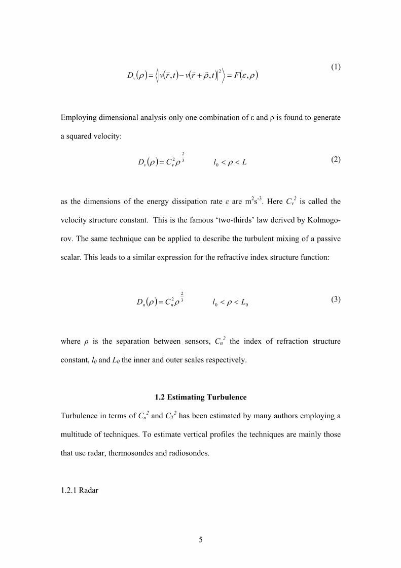
Employing dimensional analysis only one combination of ε and ρ is found to generate
a squared velocity:
( ) LlCD vv <<= ρρρ 032
2 (2)
as the dimensions of the energy dissipation rate ε are m2s-3. Here Cv2 is called the
velocity structure constant. This is the famous ‘two-thirds’ law derived by Kolmogo-
rov. The same technique can be applied to describe the turbulent mixing of a passive
scalar. This leads to a similar expression for the refractive index structure function:
( ) 0032
2 LlCD nn <<= ρρρ (3)
where ρ is the separation between sensors, Cn2 the index of refraction structure
constant, l0 and L0 the inner and outer scales respectively.
1.2 Estimating Turbulence
Turbulence in terms of Cn2 and CT
2 has been estimated by many authors employing a
multitude of techniques. To estimate vertical profiles the techniques are mainly those
that use radar, thermosondes and radiosondes.
1.2.1 Radar
5

Radar can measure the refractive index structure function because Cn2 is proportional
to the radar reflectivity, Ottersten [1969].
3/12
38.0λη⋅⎟⎠⎞
⎜⎝⎛=nC (4)
where η is the radar reflectivity and λ is the radar wavelength. A review of radar-
based measurements of Cn2 is beyond the scope of this paper. Excellent reviews of the
technique may be found in VanZandt et al [1978], Rao et al [1997] and Rao et al
[2001].
The second advantage of the radar technique is its capability to acquire data in a
systematic and continuous manner. This capability has yielded the insight that the
conditional probability distribution of Cn2 (conditioned to the presence of turbulence)
is log-normal at all heights and times, Wheelon [2001] and Nastrom et al [1986].
Unfortunately many authors, when publishing measurements of Cn2 have done so
in the form of averages (seasonal, monthly or diurnal means) with little information
on the probability distribution of the measurements, Ghosh et al [2001], Rao et al
[2001]. Often it is also not clear whether the means obtained refer only to turbulent
events, well above the minimum Cn2 detectable by the radar, or if these means are for
all measurements. The data in this form is difficult to use in any applications that
require statistical information such as those in radio-wave propagation where an
outage probability needs to be estimated.
Under an experimental point of view the radar has the disadvantage that it is an
expensive instrument to acquire and to operate. This is the reason why there are not
many around the globe when compared with for instance radiosondes.
6

1.2.2 Thermosondes
Instrumented balloons carrying pairs of sensors at a given distance (e.g. 1 meter apart)
have provided very high quality profile data.
The technique derives the one-dimensional structure function directly from
differential measurement at the two sensors, Bufton et al [1972], Barlettti et al [1976]
and Coulman [1973]
>+−=< 2)]()([)( rxTxTrDT (5)
where T is the variable measured (usually temperature), r the distance between
sensors. Local isotropy and homogeneity is assumed to derive Cn2.
This is a very powerful technique with vertical resolutions that, in principle, may be
better than those achievable by radar.
The disadvantage of this technique is that it requires specially purpose built
equipment and is limited to specific measurement campaigns. No systematic data is
available as it is more expensive than radar.
1.2.3 Radiosondes
Standard meteorological radiosondes have been used to derive Cn2 , Warnock &
VanZandt [1985], VanZandt et al [1978] and Vasseur [1999]. Radiosonde launches
are generally carried out at synoptic times (0, 6, 12 and 18 UTC) across the globe. In
more than 700 sites launches are carried out twice a day and in more than 300, four
times a day. These measurements are carried out as part of the global meteorological
network coordinated by the World Meteorological Organization.
7

Radiosondes measure all atmospheric variables of interest (pressure, humidity
and temperature as well as wind speed and direction) across the full vertical profile
however only measurements at standard and significant pressure levels are stored and
archived.
These archived measurements have typical resolutions from 100 to 1000 meters,
which are much bigger than the typical outer scales of turbulence. These resolutions
are not sufficient to characterise turbulence, which in general occurs in relatively thin
layers, and as a consequence, assumptions on the occurrence of turbulent layers are
necessary to derive Cn2. Therefore probability distributions for wind shear, buoyancy
and the outer scale of turbulence have to be assumed.
The advantage of these data is that it is easily available and covering a wide
range of climates over long periods of time (some datasets cover more than 20 years).
8

2. HIGH RESOLUTION RADIOSONDE DATA
High quality, high-resolution radiosonde data is increasingly becoming available for
scientific applications. Some research organisations have started to store and archive
the full resolution data (instead of only the standard and significant levels) from the
operational radiosonde launches. The acquisition of these data is justified when the
quality and response time of the equipment and sensors is adequate.
The British Atmospheric Data Centre has been archiving the high-resolution data
of the Vaisala RS80L radiosondes performed by the UK Met Office for around twenty
sites. This data is in the Vaisala PC-CORA binary format.
These data yield values for pressure, temperature, humidity, wind speed and
direction. Wind speed and direction are not directly measured by the radiosonde.
These are calculated from the position of the sonde at successive time intervals. The
equipment used to obtain the data is the Vaisala RS80L radiosonde. A short overview
of its technical specifications is shown below
The RS80L data employs Loran-C to determine wind speed and direction. The
estimated accuracies are 1-2 m/s and 5-10 degrees respectively. The resolution is 0.1
m/s and one degree respectively. With its sampling rate of 7 samples per 10 seconds
for each parameter it is ideally suited for this work, as this yields a data point
approximately every 8 meters of altitude, on average, given a typical radiosonde
ascent rate of about 5 meters per second. This resolution would allow in principle
allow the identification of turbulent layers, as thin as 8 meters, with no statistical
assumptions regarding the their occurrence.
9

Data from four stations has been used, their locations spread out latitudinally. As
the aim was to characterise the Cn2 for different climate types, stations were chosen at
latitudes ranging from the most northern to the most southern available. The BADC
dataset covers a wider range of years that that used here however a subset was
selected based on the availability of a maximum number of launches per day with no
gaps throughout the years.
3. METHODOLOGY
To derive Cn2 we first identify, within the data for each individual radiosonde launch,
the turbulent layers. This is done through the calculation of the Reynolds and
Richardson (Ri) numbers for each high-resolution data point.
The Potential refractive Index Gradient is derived for all layers but is only used
to derive Cn2 in those identified as turbulent (i.e. where Ri is smaller than the critical
value).
In summary the following step-by-step approach was used for each high-
resolution radiosonde data point:
1. Calculate Reynolds number.
2. Calculate Richardson number.
3. Calculate Potential Refractive Index Gradient.
4. Create data subset based on (Ri < Ricr), this contains only measurements
where the layers are turbulent.
5. Calculate structure constant (Cn2 ) for all turbulent layers and set its value for
stable layers to 10-21 m-2/3.
10

Figure 1 illustrates this methodology.
3.1 Reynolds number
The Reynolds number is used to determine whether a flow is laminar or turbulent.
Considered to be the most important dimensionless number in fluid dynamics it yields
the ratio between inertial and viscous forces. When Re exceeds a critical value a
transition of the flow from laminar to turbulent or chaotic occurs. For the atmosphere
the critical Reynolds number is around 106, 107.
νlV ⋅
=Re (6)
where V is the wind speed, l the characteristic length and ν = 1.1ּ10-5 m2/s is the
kinematic viscosity.
For the atmosphere the characteristic length has been taken to be equal to the
resolution of the radiosonde measurement. It has been included more as a measure of
completeness than as a conclusive method to determine whether or not a measurement
was turbulent. In fact, what the results show is that by definition of the Reynolds
number the entire atmosphere can be considered turbulent, which is of course the
basis for Kolmogorov's universal equilibrium theory.
3.2 Richardson number
Which radiosonde measurements are turbulent must first be established before the
structure constant can be calculated, or risk including non-turbulent measurements in
a theory that is specifically suited for turbulence only. To accomplish this the
Richardson number is calculated per measurement. Simply put the Richardson
number is a measure of how turbulent an atmospheric layer is. A stability criterion for
11
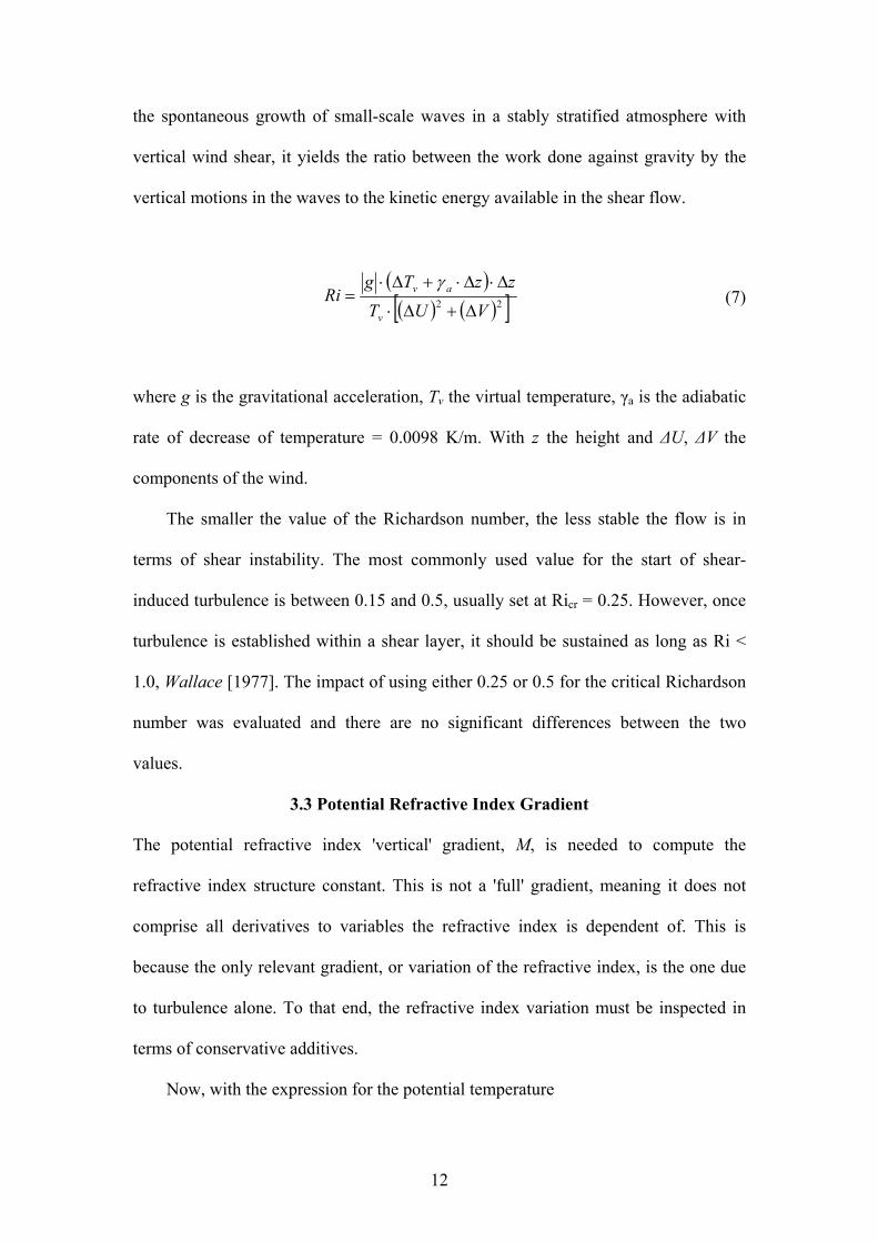
the spontaneous growth of small-scale waves in a stably stratified atmosphere with
vertical wind shear, it yields the ratio between the work done against gravity by the
vertical motions in the waves to the kinetic energy available in the shear flow.
( )( ) ( )[ ]22 VUT
zzTgRi
v
av
∆+∆⋅
∆⋅∆⋅+∆⋅=
γ (7)
where g is the gravitational acceleration, Tv the virtual temperature, γa is the adiabatic
rate of decrease of temperature = 0.0098 K/m. With z the height and ∆U, ∆V the
components of the wind.
The smaller the value of the Richardson number, the less stable the flow is in
terms of shear instability. The most commonly used value for the start of shear-
induced turbulence is between 0.15 and 0.5, usually set at Ricr = 0.25. However, once
turbulence is established within a shear layer, it should be sustained as long as Ri <
1.0, Wallace [1977]. The impact of using either 0.25 or 0.5 for the critical Richardson
number was evaluated and there are no significant differences between the two
values.
3.3 Potential Refractive Index Gradient
The potential refractive index 'vertical' gradient, M, is needed to compute the
refractive index structure constant. This is not a 'full' gradient, meaning it does not
comprise all derivatives to variables the refractive index is dependent of. This is
because the only relevant gradient, or variation of the refractive index, is the one due
to turbulence alone. To that end, the refractive index variation must be inspected in
terms of conservative additives.
Now, with the expression for the potential temperature
12

zTH a ⋅+= γ (8)
where γa the adiabatic lapse rate of temperature and z the height. And the expression
for specific humidity
peq ⋅= ε (9)
with e is the partial water vapour pressure and p the pressure and ε = 0.622 the ratio of
gas constants for dry air to that for water vapour, for an up-welling parcel of air
moving from height z1 to z2 due to turbulent mixing
( ) ( ) ( )( ) ( ) ( ) ( )( )zq
qN
zH
HNzqzHzpzNzqzHzpzNN δδ ⎟⎟
⎠
⎞⎜⎜⎝
⎛∂∂
∂∂
+∂∂
∂∂
≈−= 22221122 ,,,,,,
(10
)
where the potential refractive index gradient, M, can be written as
610−×⎟⎟⎠
⎞⎜⎜⎝
⎛∂∂
∂∂
+∂∂
∂∂
=zq
qN
zH
HNM (11)
This yields, Tatarskii [1961]
13

⎟⎟⎟⎟
⎠
⎞
⎜⎜⎜⎜
⎝
⎛
⋅+
−+⎟⎠⎞
⎜⎝⎛ ⋅+
⋅⋅−=
−
dzdq
Tqdz
dTT
qT
pM a 155001
780015500110792
6
γ (12)
A more generalised approach for M used by Warnock & VanZandt [1985] has the
form:
⎟⎟⎠
⎞⎜⎜⎝
⎛∂∂
⋅−⋅
+⋅∂
∂⋅⋅−=
−
zdzdq
TTq
zTpM
θθ
ln215500155001ln106.77 6
(13)
This formulation yields better-behaved results and will be used here. Equation 10
tends to overestimate the potential refractive index.
With these expressions Cn2 can be calculated using Tatarskii [1971]:
2340
22 MALaCn = (14)
where a2 is a dimensionless constant between 1.5 and 3.5, but most commonly used at
a value of 2.8, Monin and Yaglom [1971]. A = K/(Km(1-Ri)) is a numerical constant
generally considered equal to unity. L0 is the outer scale of turbulence, which has been
set equal to the resolution of the radiosonde data.
Using equation 12 the refractive index structure constant can be calculated for
every radiosonde measurement considered as turbulent given a sub-critical Ri-
chardson number. All necessary differentials needed to calculate the Richardson
number are determined by the values from two consecutive height measurements.
14

If a measurement is considered stable, a Cn2 value of 10-21 m-2/3 is assigned. This
value was chosen to reflect, in a simplified manner, the sensitivity of Cn2 radar
measurements and also, for convenience, since for all the results we use logarithmic
scales.
Layers with sustained turbulence, where the critical Richardson number may be
1, are in this approach considered to be stable. This will lead to an underestimation of
the statistics of Cn2 .
As radiosonde measurements do not have values for the same heights,
performing statistics on the dataset requires mapping of the Cn2 to fixed heights with
10 meter spacing. This makes it possible to arrange all data in a histogram per
location, making it readily apparent at which values the various percentiles are and
how they compare to each other. Moreover probability distribution functions (pdf)
may easily be derived for each height as cross-sections of this histogram. Note that all
stable measurements get binned to the lower excess class of the histogram of the
refractive index structure constant.
4. RESULTS AND DISCUSSION
Figure 2 shows an example of Cn2 values derived for a single launch in Camborne on
the 1st January 2002 at 5AM local time (0600 UTC).
What appears to be a vertical line on the left hand side of the figure shows the
data points that were identified as stable layers (Cn2 set to 10-21). The dots scattered
across the figure show the Cn2 values for all those data points considered to be in
turbulent layers.
15

The figure shows, as expected Bufton [1973], Barat [1982], that turbulence, in
the free atmosphere is confined to thin layers separated by non-turbulent regions .
For altitudes above around 17 km there are turbulent layers that have Cn2 values
that are smaller than that assigned to stable layers. This shows that the value of Cn2
chosen for stable layers is too high for high altitudes and this may lead to a slight
overestimation in the statistical results of Cn2 for these height ranges.
Even though this figure depicts only results for a single radiosonde launch, the
values observed are consistent with those observed by radar (e.g. Rao, VanZandt)
Figure 3 shows the histogram of Cn2 for Camborne at a height of 6000 meters. The
data shown covers a period of 4 years with 4 radiosonde launches per day. The
histogram class for stable layers (Cn2=10-21) is outside of the figure and contains
around 45% of the total number of samples (55% of the samples at this height are
turbulent and shown in the histogram). The median value of the histogram is around
10-14. It should be noted that this histogram shows only the turbulent samples and,
when normalized to the total number of turbulent samples, would represent the
probability density function conditioned to the presence of turbulence.
The log-normal behaviour of the histogram is evident and agrees with previous
observations regarding the statistical behaviour of Cn2 as discussed in section 1.2.1.
This result seems to indicate that the approach taken here is in principle correct.
Using statistical descriptors such as the mean and standard deviation care has to
be taken when either describing the full process, turbulent and stable, or only the
turbulent part.
When only considering the log-normal turbulent part, the mean and standard
deviation have to be derived using the stochastic variable log Cn2. Since the data
16

ranges over several orders of magnitude, a single high value would dominate a linear
mean which would subsequently misrepresent the turbulent part. The radar
community also uses 2log nC as in radar measurements the reflectivity is measured in
logarithmic units. Hence also for the purpose of comparison using 2log nC is a good
practice.
However, if all measurements are taken into account (turbulent and stable),
2log nC would lead to an underestimation of the mean (or median) of Cn2 when there is
turbulence. In this case, for all measurements (turbulent and stable), the linear mean
2nC will be closer to 2log nC when only turbulent measurements are considered even
if 2nC is, in the opinion of the authors, a poor descriptor for the probability of Cn
2
conditioned to the occurrence of turbulence. It should be noted that some authors have
presented mean results using the linear mean, see Vasseur [1999].
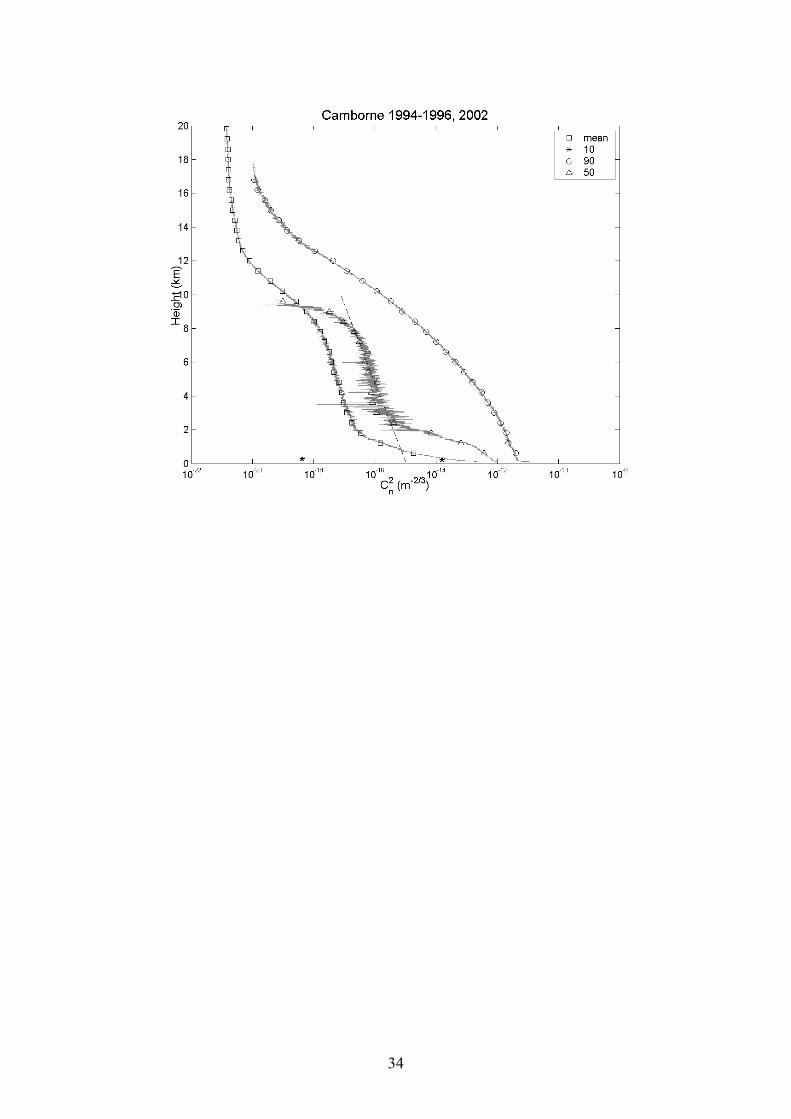
Figure 4 shows the overall statistical results for Camborne (4 years and 4 launches per
day). The results shown were derived from the cumulative distributions of Cn2 for
each height. Only the 10, 50 and 90 percentiles are shown, the 25 and 75 percentiles
were omitted so that the figure is not overcrowded.
It can be seen, for instance, that at 10 km the structure constant in the 90
percentile is approximately 10-16, indicating that only 10 % of the measurements
would exceed this value. In order to distinguish between the various lines in the figure
but preserve the visibility of the fast variation of the structure constant with height,
every thirtieth data point has been re-plotted using the various plot symbols. The
mean shown in the figure is 2log nC .
17

For applications in the troposphere where it is sufficient to use a simplified
exponential model the median is fitted to yield a single expression for the Cn2 with
height. The dashed line in the figure is the median-fit and was constructed between
2.1 and 8 km: Cn2= 1.1×10⁻¹⁵ exp(-h/2014). Note that this value is very similar to that
derived, also for the median case, for a Belgian site with a similar latitude and climate
(Uccle) by Vasseur [1999].
The probability of occurrence of turbulence as a function of height is presented in
Figure 5, this probability was derived by normalising the number turbulent samples at
a given height to the total number of samples. Figure 6 shows the percentiles of the
cumulative distribution conditioned to the occurrence of turbulence as a function of
height.
The data in Figure 4 can be derived from these two figures using:
)()()( |22 zPzPzP TurbxCnTurbxCn << ⋅= (15)
Where z is the height, x is a given value of Cn2, and PCn2>x(z), PTurb(z) and PCn2>x|
Turb(z) are represented in Figures 4, 5 and 6 respectively.
From figure 5, the probability of having a turbulent layer between 2 and 8
kilometres is always higher than 50%. This explains why the median values derived
from figure 4 are always smaller than those in figure 5, i.e. the median of all samples
underestimates the most probable case when there is turbulence. Thus the median of
the histogram in Figure 3 is Cn2=10-14, whereas the median for the overall histogram
for the same height is Cn2=10-16.
18

The presence of the boundary layer (where the atmosphere interfaces with the
surface of the Earth) can be clearly identified below 2 km where there is an increased
probability of turbulence.
Note that in figure 6 below around 12 km the percentiles are almost symmetrical
around the median. This illustrates again the log-normal behaviour of Cn2 as already
discussed for figure 3.
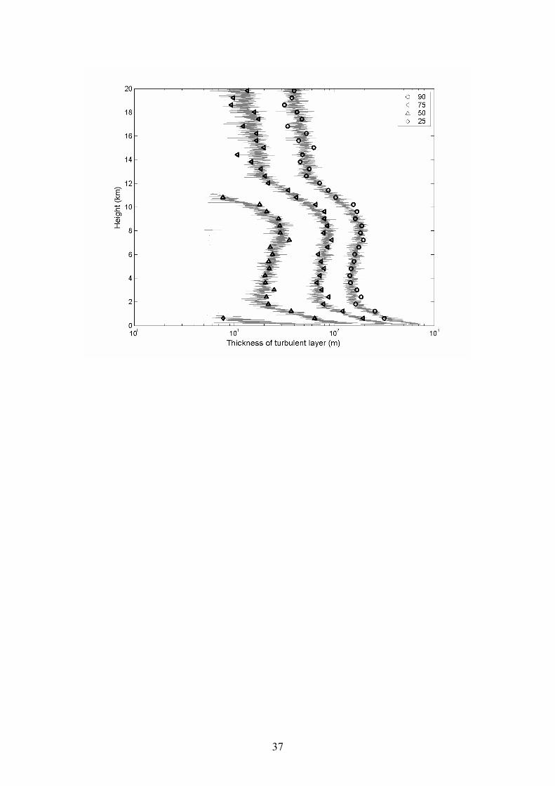
Figure 7 shows the percentiles as a function of height derived from the cumulative
distribution of the turbulent layer thickness for each height. The thickness of the
turbulent layers was derived first from the Richardson analysis (see 3.2) and then by
creating a histogram from a thickness classification for each height.
The figure shows for all percentiles above 25%, as expected, thicker turbulent
layers in the boundary layer (below 2 km), an almost constant thickness up to the
tropopause and then a decrease above it. In the stratosphere (up to 20km) the figure
shows again a slowly decreasing value.
The values shown here are consistent with those for the outer scale of turbulence
derived for different seasons in Eaton & Nastrom [1998]. The trend however is
different. This may be due to the different techniques used, different climatology and
orography (Eaton & Nastrom measurements were carried out close to a mountain
range, 2700 m) and especially due to the different variables that are being compared
(turbulent layer thickness and outer scale of turbulence).
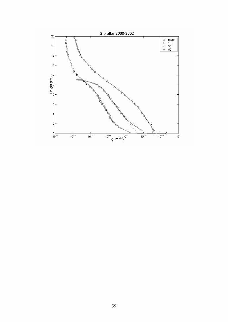
Figures 8, 9 and 10 show the results for Lerwick, Gibraltar and St. Helena in the form
of percentiles derived from the cumulative distributions of Cn2 for each height. Only
19

the 10, 50 and 90 percentiles are shown, the 25 and 75 percentiles were omitted so
that the figures are not overcrowded.
For Lerwick the median value is very low as may be expected from a northern
site. The dashed line in the figure is the median-fit and was constructed between 2 and
8 km: Cn2 = 8.9×10⁻¹⁶ exp(-h/1054). With h the height in meters.
Gibraltar shows levels of Cn2 that are much higher than expected for a site at this
latitude. This may be due to orographic effects and the proximity of the radiosonde
launches to the Rock. The median was fitted between 3 and 10 km giving Cn2 =
2.37×10⁻¹³ exp(-h/991).
St Helena shows values of Cn2 that higher than either Camborne or Lerwick as
may be expected for a site closer to the Equator. The median was fitted between 2 and
12 km: Cn2 = 6.8 ×10⁻¹⁵ e(-h/1284). The data shown in this figure is noisier than that
for all other sites, this is due to the smaller number of samples available (only one
launch per day). For the lowest altitudes a discontinuity in the data can be seen, this is
due to the altitude of the site from where the launches are performed (400 m). Some
influence of the local orography can also be observed in the median and 90%
percentile. The island has a peak at 832 meters.
20

5. CONCLUSIONS
A method to determine the refractive index structure constant, Cn2, from high-
resolution radiosonde data has been developed. A full validation of this method was
not possible to carry out due to the lack of other datasets, e.g. radar measurements.
However, the results obtained present the values and behaviour similar and within the
range of those observed by other authors. The statistical behaviour of Cn2 also shows
the expected log-normality further confirming the general correctness of the approach.
The distributions of turbulent layer thickness are as well within the range of those
observed for the outer scale turbulence providing further reassurance on the taken
approach. Statistical results were obtained for 4 sites at different latitudes as well as
an exponential fit to the median for applications where simplified models for Cn2
suffice. These statistical results show the expected physical impact of the boundary
layer, orographic features and local climate.
The authors expect that further work will lead to the full validation of the method
and that high-resolution radiosonde data may become of widespread use, due to its
availability, to determine turbulence and its parameters.
Acknowledgements
The authors would like to thank the British Atmospheric Data Centre and the UK
MetOffice for providing access to its excellent database of high-resolution radiosonde
data. They would like to thank Danielle Vanhoenacker as well for providing the raw
data as used by Hugues Vasseur in his paper. Special mention has to be made of
Pierluigi Silvestrin for his unwaivering support to this activity and of Gottfried
21
Kirchengast and Per Høeg for the constructive criticism in the many discussions with
the authors.
REFERENCES
Barat, J., “Some characteristics of clear-air turbulence in the middle stratosphere”, J.
Atmos. Sci., vol. 32, pp 2553-2564, 1982.
Barletti, R., Ceppatelli, G., Paterno, L., Righini, A., Speroni, N., “Mean vertical
profile of atmospheric turbulence relevant for astronomical seeing”, Journal of the
Optical Society of America, vol. 66, no. 12, pp 1380—1383, 1976.
Bufton, J.L., Minott, P.O., Fitzmaurice, M.W., Titterton, P.J., “Measurements of
turbulence profiles in the troposphere”, Journal of the Optical Society of America,
vol. 62, no. 9, pp 1117—1120, 1972.
Bufton, J.L., “Correlation of microthermal turbulence with meteorological soundings
in the troposphere”, Journal of Atmospheric Science, vol. 30, pp 83—87, 1973.
Coulman, C.E., “Vertical profiles of small-scale temperature structure in the
atmosphere”, Bound.-Layer Meteor., vol. 4, pp 169—177, 1973.
Dole, J., Wilson, R., Dalaudier, F., Sidi, C., “Energetics of small scale turbulence in
the lower stratosphere from high resolution radar measurements”, Ann. Geophys., vol.
19, pp 945—952, 2001.
22

Eaton, F.D., Nastrom, G.D., “Preliminary estimates of the vertical profiles of inner
and outer scales from White Sands Missile Range, New Mexico, VHF radar
observation”, Radio Sci., vol. 33, no. 4, pp 895—903, 1998.
European Space Agency, ESA SP-1279 (4) – ACE+ - Atmosphere and Climate
Explorer, Reports for Mission Selection, The Six Candidate Earth Explorer Missions,
ESA, April 2004
Ghosh, A.K., Siva Kumar, V., Kshore Kumar, K., Jain, A.R., “VHF radar observation
of atmospheric winds, associated shears and Cn2 at a tropical location:
interdependence and seasonal pattern”, Ann. Geophys., vol. 19, pp 965—973, 2001.
Ishimaru, A., “A new approach to the problem of wave fluctuations in localized
smoothly varying turbulence”, IEEE Trans. Antennas Propag., AF-21(1), 1973.
Kolmogorov, A. N., “The Local Structure of Turbulence in Incompressible Viscous
Fluid for Very Large Reynolds’ Numbers”, Comptes Rendus (Doklady) de l’Academie
des Sciences de l’URSS, vol. 30, pp 301--305, 1941
Monin, A. S. and A. M. Yaglom, Statistical Fluid Mechanics, MIT Press, Cambridge,
Massachusetts 1971.
Nastrom, G.D., Gage, K.S., Ecklund, W.L., “Variability of turbulence, 4-20 km, in
Colorado and Alaska from MST radar observations”, J. Geophys. Res., vol. 91, pp
6722—6734, 1986.
23

Ottersten, H., “Atmospheric structure and radar backscattering in clear air”, Radio
Sci., vol. 4, no. 12, pp 1179—1193, 1969.
Ottersten, H., “Mean vertical gradient of potential refractive index in turbulent mixing
and radar detection of CAT”, Radio Sci., vol. 4, no. 12, pp 1247—1249, 1969.
Rao, D.N., Kishore, P., Rao, T.N., Rao, S.V.B., Reddy, K.K., Yarraiah, M., Hareesh,
M., “Studies on refractivity structure constant, eddy dissipation rate, and momentum
flux at a tropical latitude”, Radio Sci., vol. 32, no. 2, pp 1375—1389, 1997.
Rao, D.N., Rao, T.N., Venkataratnam, M., Thulasiraman, S., Rao, S.V.B.,
Srinivasulu, P., Rao, P.B., “Diurnal and seasonal variability of turbulence parameters
observed with Indian mesosphere-stratosphere-troposphere radar”, Radio Sci., vol. 36,
no. 6, pp 1439—1457, 2001.
Richardson, L. F., Weather Prediction by Numerical Process, Cambridge University
Press, Cambridge, 1922
Stull, R. B., Meteorology for Scientists and Engineers, Brooks/Cole, Pacific Grove,
2000.
Tatarskii, V. I., Wave Propagation in a Turbulent Medium, McGraw -Hill, New York,
1961.
24

Tatarskii, V. I., The Effects of the Turbulent Atmosphere on Wave Propagation, Israel
Program for Scientific Translations Ltd., Jerusalem, 1971.
Thompson, M.C., Marler, F.E., Allen, K.C., “Measurement of the microwave
structure constant profile”, IEEE Trans. Antennas Propag., vol. AP-28, no. 2, pp
278—280, 1980.
VanZandt, T.E., Green, J.L., Gage, K.S., Clark W.L., “Vertical profiles of refractivity
turbulence structure constant: Comparison of observations by the Sunset Radar with a
new theoretical model”, Radio Sci., vol. 13, no. 5, pp 819—829, 1978.
Vasseur, H., "Prediction of Tropospheric Scintillation on Satellite Links from
Radiosonde Data", IEEE Trans. Antennas Propag., vol. 47, 2, pp. 293--301, 1999.
Wallace, J. M. and P. V. Hobbs, Atmospheric Science: An Introductory Survey, pp
437-439, Academic Press, San Diego, 1977.
Warnock, J. M. and T. E. VanZandt, "A statistical model to estimate the refractivity
turbulence structure constant Cn2 in the free atmosphere", NOOA Tech. Memo ERL,
AL-10, Aeronom. Lab., Boulder, CO, 1985
Wheelon, A. D., Electromagnetic Scintillation, I. Geometrical Optics, Cambridge
University Press, Cambridge, 2001.
25
Woo, R., Ishimaru, A., “Effects of turbulence in a planetary atmosphere on radio
occultation”, IEEE Trans. Antennas Propag., AF-22(4), 1974.
26

Table 1: Technical specifications of the Vaisala RS80 radiosonde.
Table 2: Radiosonde stations
Figure 1: Block diagram of methodology
Figure 2: Cn2 for a single radiosonde launch (Camborne 1st January 2002 at 0600
UTC). Data points at 10-21 represent stable layers while scattered data points show Cn2
for turbulent layers
Figure 3: Histogram of Cn2 at a height of 6000 meters. Data covers 4 years (1994-
1996, 2002) of 4 daily radiosonde launches in Camborne.
Figure 4: Mean of log Cn2 and 10, 50 and 90 percentiles as a function of height
derived from the cumulative distribution of Cn2 for Camborne (data comprising 4
years of 4 daily launches).
Figure 5: The probability of turbulence as a function of height for Camborne (data for
4 years of 4 daily launches).
Figure 6: Percentiles derived from the probability distribution of Cn2 conditioned to
having turbulence at Camborne (data for 4 years of 4 daily launches).
Figure 7: Percentiles as a function of height for the thickness of the turbulent layer.
The percentiles refer only to turbulent samples.
27

Figure 8: Mean of log Cn2 and 10, 50 and 90 percentiles as a function of height
derived from the cumulative distribution of Cn2 for Lerwick.
Figure 9: Mean of log Cn2 and 10, 50 and 90 percentiles as a function of height
derived from the cumulative distribution of Cn2 for Gibraltar.
Figure 10: Mean of log Cn2 and 10, 50 and 90 percentiles as a function of height
derived from the cumulative distribution of Cn2 for St. Helena.
28
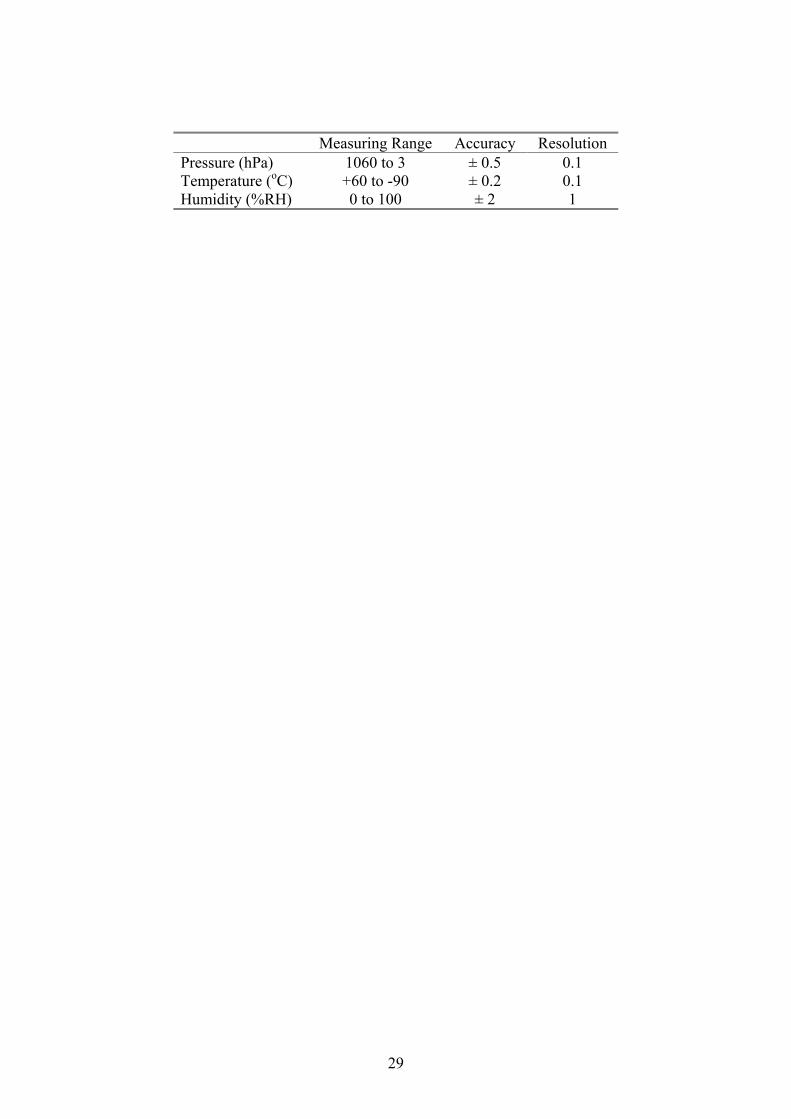
Measuring Range Accuracy Resolution Pressure (hPa) 1060 to 3 ± 0.5 0.1 Temperature (oC) +60 to -90 ± 0.2 0.1 Humidity (%RH) 0 to 100 ± 2 1
29

Latitude
(o) Longitude
(o) AMSL
(m) Launches
UTC Years of
data Lerwick 60.13 N 1.18 W 82 00, 06, 12, 18 99-02 Camborne 50.22 N 5.32 W 88 00, 06, 12, 18 94-96, 02 Gibraltar 36.14 N 5.35 W 10 00, 12 00-02 St. Helena 15.23 S 5.18 W 400 12 00, 02
30

DATA CORRECT FORUNITS
REYNOLDSNUMBER
RICHARDSONNUMBER
POTENTIALREFRACTIVE
INDEXGRADIENT
Ri < Ricr
CALCULATE Cn2 SET Cn
2 TO 10-21
TURBULENT LAYERS STABLE LAYERS
31

32

33
34

35

36
37

38
39

40