Embed Size (px)
Citation preview
Candidate 1 evidence
Advanced Higher Physics
This investigation was created to accurately measure the refractive index of a medium through
different methods and evaluate these experiments accordingly.
Measuring the Refractive Index
Comparing Methods
Adv Higher Physics Project 2019 Candidate 1
SQA | www.understandingstandards.org.uk 1 of 26
Contents
Abstract 3
Underlying Physics 3
Determination of the refractive index of water using a concave mirror (Method 1) 6
Determination of the Refractive Index of Glass and a Liquid using a Travelling Microscope
(Method 2)
12
Determination of the Refractive Index of a small volume of water using Wollaston’s Method
(Method 3)
20
Overall Conclusion 25
Overall Evaluation 25
References 26
Adv Higher Physics Project 2019 Candidate 1
SQA | www.understandingstandards.org.uk 2 of 26
Abstract
This investigation will compare methods of measuring the refractive index of a medium and evaluate
these experiments accordingly. All three methods measured the refractive index with some degree
of accuracy and precision.
Method 1 using a concave mirror was the most simple to undertake and produced accurate results
(most accurate being 1.32±0.04) for which the given value was within the maximum uncertainty.
Method 2 using a travelling microscope was more difficult to carry out but allowed the refractive
index of both a liquid and a solid, i.e. glass or Perspex. This method resulted in values lower than the
accepted value (1.43±0.12) for glass which shows a systematic error but was still accurate enough
for the accepted value to lie within the uncertainties of the experiment. Measuring the refractive
index of water was a lot more inconsistent than the glass.
Method 3 also can only measure the refractive index of a small volume of liquid, not solid. Although
it produced the most accurate results but required custom building of apparatus. The uncertainties
were quite large though (1.32±0.09) which shows the experiment could have a lot of errors.
Underlying Physics
Light travels at different speeds through different mediums. The speed that light travels at is
dependent on the refractive index of the medium. Take a red laser shining at an angle into a glass
block as shown below.
Adv Higher Physics Project 2019 Candidate 1
SQA | www.understandingstandards.org.uk 3 of 26

Figure 1: http://hyperphysics.phy-astr.gsu.edu?hbase/geopt/refr.html#c3
Air has a refractive index of 1.0003, rounded to 1, and glass has a considerably higher refractive
index of around 1.5 depending on the type of glass. This cause the light ray to slow as it enters the
medium and increase in speed as it leaves the medium. Snell’s Law states that the refractive index
of the first medium, n1, divided by the refractive index of the second medium, n2, is equal to sinθ1
divided by sinθ2, or:
2 1
1 2
sin
sin
n
n
As previously stated, the refractive index of air is 1 which allows for the equation to be simplified to,
12
2
sin
sinn
When water is poured into the mirror (method 1) the light will be refracted and the reflected ray will
return to a different position. Finding the point of non-parallax allows measurements to be taken
that can calculate refractive index using Snell’s Law.
Adv Higher Physics Project 2019 Candidate 1
SQA | www.understandingstandards.org.uk 4 of 26

Figure 2: http://astro.unl.edu/naap/distance/parallax.html
Parallax involves the use of two different points of view. This could be a human’s eyes or cameras
on either side of the world. When an object is seen from two points of view, it moves relative to its
background and surrounding objects. Measuring the angle at which these lines of sight view the
object can determine the how far away the object is. This is how humans and most predatory
animals perceive depth and astronomers measure the distance to closer stars. When looking at the
pin and the reflected image in a concave mirror, moving the view position will cause the pin and the
reflected image to move different distances. The point of non-parallax occurs when both the
movement of the reflected image of the pin and the real pin coincide. The distance between the
image and the pin should never change, as shown in the diagram below, with the black pin being the
start position of the pin. The red pin occurs when the view position is moved left to right. Using the
point of non-parallax in this experiment allows for the exact change in distance that the reflected ray
takes due to the water in the mirror.
Adv Higher Physics Project 2019 Candidate 1
SQA | www.understandingstandards.org.uk 5 of 26
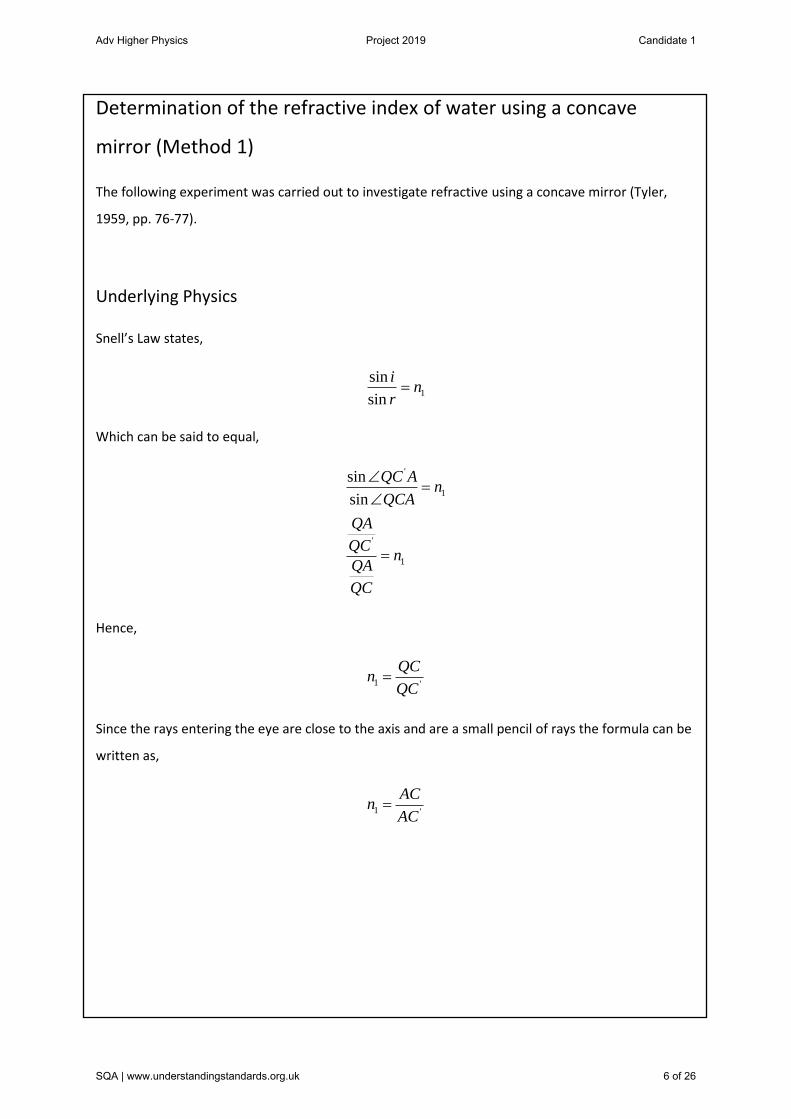
Determination of the refractive index of water using a concave
mirror (Method 1)
The following experiment was carried out to investigate refractive using a concave mirror (Tyler,
1959, pp. 76-77).
Underlying Physics
Snell’s Law states,
1
sin
sin
in
r
Which can be said to equal,
'
1
'
1
sin
sin
QC An
QCA
QA
QCn
QA
QC
Hence,
1 '
QCn
QC
Since the rays entering the eye are close to the axis and are a small pencil of rays the formula can be
written as,
1 '
ACn
AC
Adv Higher Physics Project 2019 Candidate 1
SQA | www.understandingstandards.org.uk 6 of 26
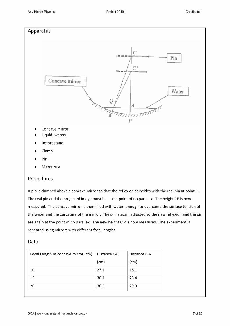
Apparatus
Concave mirror
Liquid (water)
Retort stand
Clamp
Pin
Metre rule
Procedures
A pin is clamped above a concave mirror so that the reflexion coincides with the real pin at point C.
The real pin and the projected image must be at the point of no parallax. The height CP is now
measured. The concave mirror is then filled with water, enough to overcome the surface tension of
the water and the curvature of the mirror. The pin is again adjusted so the new reflexion and the pin
are again at the point of no parallax. The new height C’P is now measured. The experiment is
repeated using mirrors with different focal lengths.
Data
Focal Length of concave mirror (cm) Distance CA
(cm)
Distance C'A
(cm)
10 23.1 18.1
15 30.1 23.4
20 38.6 29.3
Adv Higher Physics Project 2019 Candidate 1
SQA | www.understandingstandards.org.uk 7 of 26

30 52.5 39.1
Inconsistent Focal Length (Flexible
Mirror)
61.7 49.2
Analysis:
Mirror with focal length of 10 cm,
CA = 23.1
C’A = 18.1
1
23.11.28
' 18.1
CAn
C A
Focal Length of concave mirror (cm) Calculated refractive Index of Water
10 1.28±0.06
15 1.29±0.05
20 1.32±0.04
30 1.34±0.03
Inconsistent Focal Length (Flexible
Mirror)
1.25±0.02
Adv Higher Physics Project 2019 Candidate 1
SQA | www.understandingstandards.org.uk 8 of 26

1.10
1.15
1.20
1.25
1.30
1.35
1.40
10 15 20 30 Inconsistent FocalLength (Flexible
Mirror)
Cal
cula
ted
ref
ract
ive
Ind
ex o
f W
ater
Focal Length (cm)
Calculated refractive Index of Water
Adv Higher Physics Project 2019 Candidate 1
SQA | www.understandingstandards.org.uk 9 of 26

Uncertainties
Uncertainty is distance CA for data using mirror of focal length 10 cm:
Metre rule calibration uncertainty = ±0.5cm
Reading uncertainty = ±0.5cm
Total uncertainty:
2 2(0.5) (0.5)
0.5
= ±0.7 cm
Total percentage uncertainty:
0.7100
23.1
3.03%
Uncertainty in distance C’A for data using mirror of focal length 10cm:
Metre rule calibration uncertainty = ±0.5cm
Reading uncertainty = ±0.5cm
Total uncertainty:
2 2(0.5) (0.5)
0.5
= ±0.7 cm
Total percentage uncertainty:
0.7100
18.1
3.87%
Uncertainty in refractive index:
2 2(3.03) (3.87)
Adv Higher Physics Project 2019 Candidate 1
SQA | www.understandingstandards.org.uk 10 of 26

24.16
4.9%
Therefore total absolute uncertainty for the refractive index:
1.284.9
100
0.06
Conclusion:
As the given value for the refractive index of water is 1.33, the most accurate mirrors also had the
longest focal length. The mirror with the longest focal length, 30 cm, gave the refractive index to be
1.34±0.03, extremely close to the given value. The mirror with a focal length of 20cm, gave the
refractive index of 1.32±0.04, equally close to the given value. The least accurate of all the mirrors
was the flexible mirror, with a result of 1.25±0.02.
Evaluation of Procedures:
Using a ruler to measure the distance from the mirror to the pin can be inaccurate because the flat
edge of the ruler will not sit flush to the curved mirror, leading to a small distance being measured.
This could be reduced if a thin metal rod was used and marked to the height of the pin, and then
measured with a ruler.
A flexible mirror is definitely inaccurate as the concavity changes throughout the mirror due to years
in storage. This causes the mirror to have no point of non-parallax and in turn causes the
experiment to fail. As the observer moved to find the point of non-parallax the concavity changed,
making the point of non-parallax change. The point closest to the point of non-parallax was used
instead and produced inaccurate results as expected.
The experiment produced a refractive index close to that of water, excluding the flexible mirror. The
refractive indices measured with mirrors that had longer focal lengths were more accurate than
mirrors with short focal lengths. This could be because a misjudgement when finding the point of
non-parallax which is found by eye thus may be inaccurate and will be more prominent at smaller
focal lengths.
Adv Higher Physics Project 2019 Candidate 1
SQA | www.understandingstandards.org.uk 11 of 26

Determination of the Refractive Index of Glass and a Liquid using a
Travelling Microscope (Method 2)
The following experiment was carried out to investigate refractive index using a travelling
microscope.
Underlying Physics
The travelling microscope allows for the measurement of very small distances. The difference in
distance travelled by a ray of light passing through air and a ray of light passing thorough glass can
be measured. Again Snell’s law can be used to determine the refractive index.
Snell’s law states:
sin
sina
in
r
Which can be said to equal,
sin
sin '
'
a
a
APQn
AP Q
AQ
PQn
AQ
P Q
Adv Higher Physics Project 2019 Candidate 1
SQA | www.understandingstandards.org.uk 12 of 26

Hence,
1
'g
a
PQn
n P Q
For extremely small angles PQ and P’Q can be equal PA and P’A respectively, as the distance AQ is
negligible.
real thickness
' apparent thicknessg
PAn
P A
Apparatus:
Adv Higher Physics Project 2019 Candidate 1
SQA | www.understandingstandards.org.uk 13 of 26

Travelling microscope with Vernier scale
Glass block
Tank with glass sides
Lycopodium powder
Fine sand
Description of Procedures:
A piece of paper is placed on the bench with and marked with an ink spot ‘P’. A travelling
microscope is adjusted to bring P into focus and arranged to move vertically. Arranging the
microscope to move vertically in one direction prevents ‘flyback’ which can cause an error with the
measurement. An initial reading on the Vernier scale is taken. The glass block is now placed in a
position over P, between the paper and the travelling microscope. The microscope is now
positioned and re-adjusted to bring P into focus. The Vernier is read at P’. An ink spot is made on
the top of the glass block and the travelling microscope is adjusted to bring it into focus. Finally the
Vernier is read (A).
To measure the refractive index of a liquid, the same procedure is taken except the first and second
reading is taken on sand particles at the bottom of the tank (the first has no liquid in the tank) and
the third is taken on the particles of lycopodium powder floating on the surface of the liquid.
Data:
Measuring the Refractive Index of Water
Try 1 Try 2 Try 3
Measurement No.1 (mm) (1) 99.0 99.0 100.0
Measurement No.2 (mm) (2) 100.6 100.1 100.9
Measurement No.3 (mm) (3) 104.5 105.6 106.3
Adv Higher Physics Project 2019 Candidate 1
SQA | www.understandingstandards.org.uk 14 of 26
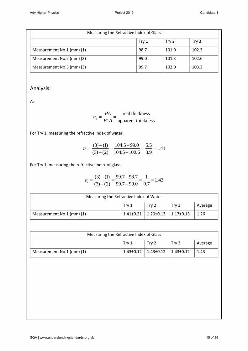
Measuring the Refractive Index of Glass
Try 1 Try 2 Try 3
Measurement No.1 (mm) (1) 98.7 101.0 102.3
Measurement No.2 (mm) (2) 99.0 101.3 102.6
Measurement No.3 (mm) (3) 99.7 102.0 103.3
Analysis:
As
real thickness
' apparent thicknessg
PAn
P A
For Try 1, measuring the refractive index of water,
(3) (1) 104.5 99.0 5.51.41
(3) (2) 104.5 100.6 3.9ln
For Try 1, measuring the refractive index of glass,
(3) (1) 99.7 98.7 11.43
(3) (2) 99.7 99.0 0.7ln
Measuring the Refractive Index of Water
Try 1 Try 2 Try 3 Average
Measurement No.1 (mm) (1) 1.41±0.21 1.20±0.13 1.17±0.13 1.26
Measuring the Refractive Index of Glass
Try 1 Try 2 Try 3 Average
Measurement No.1 (mm) (1) 1.43±0.12 1.43±0.12 1.43±0.12 1.43
Adv Higher Physics Project 2019 Candidate 1
SQA | www.understandingstandards.org.uk 15 of 26

0.00
0.20
0.40
0.60
0.80
1.00
1.20
1.40
1.60
1.80
1 2 3 4 5 6 7
Cal
cula
ted
ref
ract
ive
Ind
ex
Axis Title
Determination of the Refrative Index of Glass and a Liquid using a Travelling Microscope (Method 2)
Series1 Series2
Try 1 Try 2 Try 3 Try 1 Try 2 Try 3Water Glass
Adv Higher Physics Project 2019 Candidate 1
SQA | www.understandingstandards.org.uk 16 of 26

Uncertainties:
Reading uncertainty for travelling microscope,
1of the smallest division
2
1= 0.1
2
0.05
mm
mm
Random uncertainties:
max minrandom uncertaint
measurement measurementy
n
For distance (3) – (1) in refractive index of water,
6.6 5.5
3
0.37mm
For distance (3) – (2) in refractive index of water,
5.5 3.9
3
0.53mm
For distance (3) – (1) in refractive index of glass,
1 1
3
0mm
For distance (3) – (2) in refractive index of glass,
0.7 0.7
3
0mm
Adv Higher Physics Project 2019 Candidate 1
SQA | www.understandingstandards.org.uk 17 of 26
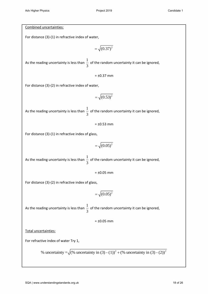
Combined uncertainties:
For distance (3)-(1) in refractive index of water,
2(0.37)
As the reading uncertainty is less than 1
3 of the random uncertainty it can be ignored,
= ±0.37 mm
For distance (3)-(2) in refractive index of water,
2(0.53)
As the reading uncertainty is less than 1
3 of the random uncertainty it can be ignored,
= ±0.53 mm
For distance (3)-(1) in refractive index of glass,
2(0.05)
As the reading uncertainty is less than 1
3 of the random uncertainty it can be ignored,
= ±0.05 mm
For distance (3)-(2) in refractive index of glass,
2(0.05)
As the reading uncertainty is less than 1
3 of the random uncertainty it can be ignored,
= ±0.05 mm
Total uncertainties:
For refractive index of water Try 1,
2 2% uncertainty = (% uncertainty in (3) - (1)) (% uncertainty in (3) - (2))
Adv Higher Physics Project 2019 Candidate 1
SQA | www.understandingstandards.org.uk 18 of 26

2 2(6.73) (13.59)
229.97
15.16%
1.41absolute uncertainty = 15.16
100
0.21
Conclusion:
The results for the refractive index of water were not very precise as shown in the graph but did
average out at 1.26 which is only 0.07 away from the given value. The results for the refractive index
of glass were extremely precise (all three results being 1.43±0.12) but still fairly inaccurate, again
averaging to be 0.07 away from the given value of the refractive index of glass of 1.5.
Evaluation of procedures:
The travelling microscope used could not slide as far as the width of the glass block in the apparatus
diagram. A glass microscope slide was used instead which is much thinner which allowed the
travelling microscope to easily take measurements. It was also extremely uniform and gave very
precise results.
The glass tank pictured has a curved bottom which meant the sand particles on the bottom of the
tank were different distances from the surface and the lycopodium powder granules. To avoid this,
the microscope was kept still when adding the lycopodium powder to make sure the measurements
were correct. To avoid this complication a glass tank with a flat bottom could have been used but
due to limited resources this was not possible.
Adv Higher Physics Project 2019 Candidate 1
SQA | www.understandingstandards.org.uk 19 of 26
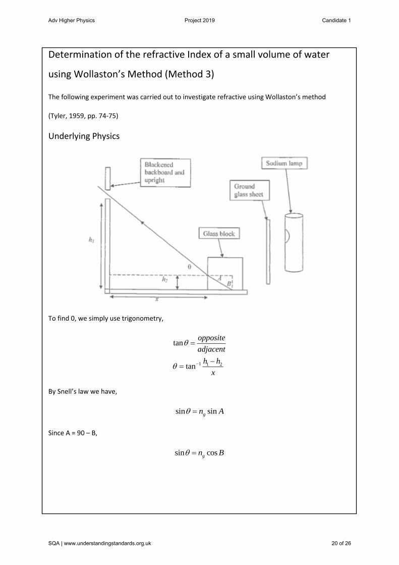
Determination of the refractive Index of a small volume of water
using Wollaston’s Method (Method 3)
The following experiment was carried out to investigate refractive using Wollaston’s method
(Tyler, 1959, pp. 74-75)
Underlying Physics
To find 0, we simply use trigonometry,
1 1 2
tan
tan
opposite
adjacent
h h
x
By Snell’s law we have,
sin singn A
Since A = 90 – B,
sin cosgn B
Adv Higher Physics Project 2019 Candidate 1
SQA | www.understandingstandards.org.uk 20 of 26

Also,
sin
sin 90
sin
ll
g
l g
nCn
n
n n C
From both these equation we can square and add to get,
2 2sinl gn n
Thus the refractive index of the liquid can be found if the refractive index of the glass block is known.
Apparatus:
Sodium lamp
Ground glass sheet
Liquid (water)
Adv Higher Physics Project 2019 Candidate 1
SQA | www.understandingstandards.org.uk 21 of 26

Glass block with horizontal scratch on one face
Blackened baseboard with upright attached at 90° and near the upper end of the upright a
slit for observation
Description of Procedures:
The apparatus was set up as shown above. A small amount of water was poured onto the base
board, and the glass cube is placed on the water with the scratch facing towards the observation slit.
When looking through the narrow slit at the cube while it is some distance away, the viewer should
see the surface of the glass that is touching the water illuminated brightly. Upon moving the cube
closer to the observation slit the illuminated surface will become darker. The cube is moved into a
position where the line of demarcation between the dark and the light fields coincides with the
scratch on the glass block. The distance of the observation slit and the scratch from the baseboard
are measured (h1 and h2 respectively). Also the distance from the upright board to the nearest face
of the cube is measured (x).
Data:
Try 1 Try 2 Try 3
h1 (cm) 24.5 24.5 24.5
h2 (cm) 1.1 1.1 1.1
x (cm) 22.7 22.3 21.6
Analysis:
1 1 2
1
tan
24.5 1.1tan
22.7
45.87
h h
x
Adv Higher Physics Project 2019 Candidate 1
SQA | www.understandingstandards.org.uk 22 of 26

Using the refractive index of the glass cube as 1.5,
2 2
2 2
sin
(1.5) sin (45.87)
1.735
1.32
l g
l
l
l
n n
n
n
n
Try 1 Try 2 Try 3
Calculated Refractive Index 1.32±0.09 1.31±0.09 1.31±0.09
0
0.2
0.4
0.6
0.8
1
1.2
1.4
1.6
1 2 3
Cal
cula
ted
Ref
ract
ive
Ind
ex
Determination of the Refractive Index of a small volume of water using Wollaston's Method (Method3)
Adv Higher Physics Project 2019 Candidate 1
SQA | www.understandingstandards.org.uk 23 of 26
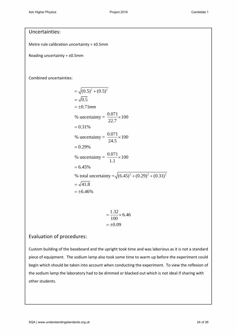
Uncertainties:
Metre rule calibration uncertainty = ±0.5mm
Reading uncertainty = ±0.5mm
Combined uncertainties:
2 2
2 2 2
(0.5) (0.5)
0.5
0.71
0.071% uncertainty = 100
22.7
0.31%
0.071% uncertainty = 100
24.5
0.29%
0.071% uncertainty = 100
1.1
6.45%
% total uncertainty = (6.45) (0.29) (0.31)
41.8
6.46%
mm
1.326.46
100
0.09
Evaluation of procedures:
Custom building of the baseboard and the upright took time and was laborious as it is not a standard
piece of equipment. The sodium lamp also took some time to warm up before the experiment could
begin which should be taken into account when conducting the experiment. To view the reflexion of
the sodium lamp the laboratory had to be dimmed or blacked out which is not ideal if sharing with
other students.
Adv Higher Physics Project 2019 Candidate 1
SQA | www.understandingstandards.org.uk 24 of 26
Overall Conclusion
All three methods have strengths and weaknesses. The most accurate experiment was method 3,
although it was not the simplest to set up. The simplest had to be method 1 which required few
pieces of apparatus and was easy to carry out. However method 2 was the only experiment to
measure both the refractive index of a liquid and the refractive index of a solid. Overall method 3
proved to be the best as accuracy is key when carrying out experiments and once the baseboard was
built the experiment was fairly straight forward to carry out.
Overall Evaluation
All three experiments worked well to give accurate results. To make the results even more reliable,
each experiment could be carried out again and the results averaged. For method 1, a concave
mirror with a focal length of 25cm could have been bought and used instead of the flexible mirror to
give a more standard set of results but due to resources and time this was not an option. Also
another experiment could be used, such as ‘Determination o the index of refraction using a laser
pointer’ (source: http://www.cuhou.net/index.php/exercises-mainmenu-13/classroom-experiments-
and-activities-mainmenu-186/203-determination-of-the-index-of-refraction-using-a-laser-pointer )to
compare results with other experiments, adding to the degree of validity.
Adv Higher Physics Project 2019 Candidate 1
SQA | www.understandingstandards.org.uk 25 of 26

References:
1. http://hyperphysics.phy-astr.gsu.edu?hbase/geopt/refr.html#c3 22 Mar. 16
2. http://astro.unl.edu/naap/distance/parallax.html 22 Mar. 16
3. Tyler F, A Laboratory manual of physics, 2nd ed., London, Edward Arnold, 1959, pp76-77
4. http://sisphysics.weebly.com/uploads/7/9/7/5/797568/11_refractive-
index_using_concave_mirror.pdf 18 April 16
5. Tyler F, A Laboratory manual of physics, 2nd ed., London, Edward Arnold, 1959, pp70-71
6. http://www.Indte.com/TEXT%20BOOKS/Book-Unit%20wise.Engineering%20Physics-
1%20&c%20HPhysics/Sem-2%Partical.pdf 18 April 16
7. Tyler F, A Laboratory manual of physics, 2nd ed., London, Edward Arnold, 1959, pp74-75
8. http://www.cuhou.net/index.php/exercises-mainmenu-13/classroom-experiments-and-
activities-mainmenu-186/203-determination-of-the-index-of-refraction-using-a-laser-pointer
22 April 16
Adv Higher Physics Project 2019 Candidate 1
SQA | www.understandingstandards.org.uk 26 of 26


![REFRACTIVE INDICES DETERMINATION OF A NEW … · extraordinary refractive index, ... [1-3], the hollow prism technique [4,5] ... Refractive indices determination of a new nematic](https://img.dokumen.tips/doc/110x75/5ac1302a7f8b9a433f8c8ea2/refractive-indices-determination-of-a-new-refractive-index-1-3-the-hollow.jpg)