Embed Size (px)
Citation preview

TIMELINING THE CONSTRUCTION IN IMMERSIVE VIRTUAL REALITY
SYSTEM USING BIM APPLICATION
A Thesis
by
KARTEEK KUNCHAM
Submitted to the Office of Graduate Studies of
Texas A&M University
in partial fulfillment of the requirements for the degree of
MASTER OF SCIENCE
Chair of Committee, Julian Kang
Committee Members, Boong Yeol Ryoo
John Walewski
Head of Department, Joe Horlen
August 2013
Major Subject: Construction Management
Copyright 2013 Karteek Kuncham

ii
ABSTRACT
Architectural, Engineering, and Construction (AEC) industry has been using 4D
construction models (graphical illustration of the construction of a 3D building design
with time as the 4th dimension) for many years to improve an existing construction
schedule by identifying inconsistencies and out of sequence activities; reducing missing
activities; and improving the ability to communicate construction plan information. In
practice, majority of the AEC industry has been using a personal computer based
monitor to view and analyze these models.
A study on investigating the potential benefits and challenges of using an
immersive 3D virtual environment to view 4D models proved that by interactively
generating construction schedule in the immersive virtual environment, the construction
professionals were able to identify design, constructability, sequencing, and
interdisciplinary interfacing issues which resulted in the construction professionals being
able to develop a plan that resulted in a 28% savings to their original schedule. The
major shortcoming of these immersive virtual reality systems was the Building
Information Models (BIM) had to be converted to a specific format before they can be
visualized in the immersive virtual environments.
This study is an attempt to address the shortcomings of the previous version of
the BIM CAVE which had the control over the camera views for achieving an almost
seamless immersive virtual environment by developing a new BIM CAVE application
which synchronizes timelining of 4D construction sequence in BIM CAVE. The new

iii
BIM CAVE setup is run by a custom built application that makes use of the .Net API
(Application Programming Interface) of the commercially available BIM application,
Autodesk Navisworks 2012.
The objective of this research is to investigate the effectiveness, potential
benefits and challenges of timelining the 4D construction sequence in BIM CAVE
developed at Texas A&M University by using a qualitative research methodology called
phenomenological study.
The findings of this research specify that timelining the 4D construction
sequence in BIM CAVE has many potential benefits like better spatial perception which
increases confidence of construction professionals over the schedule, better sequencing
of construction activities, better communication of schedule, evaluating constructability
issues, and training the work force. Thus, this research concludes that timelining the
construction in BIM CAVE is effective over visualizing 4D construction on a single
screen with some limitations mentioned in this research.

iv
ACKNOWLEDGEMENTS
I would like to thank my committee chair, Dr. Julian Kang, and my committee
members, Dr. Boong Yeol Ryoo, Dr. John Walewski, for their guidance and support
throughout the course of this research.
Thanks also go to my friends and colleagues and the department faculty and staff
for making my time at Texas A&M University a great experience. I also would like to
extend my gratitude to the industry professionals for participating in my research.
Finally, thanks to my mother and father for their encouragement and to my
sisters for their support.

v
TABLE OF CONTENTS
Page
ABSTRACT .................................................................................................................. ii
ACKNOWLEDGEMENTS .......................................................................................... iv
TABLE OF CONTENTS ............................................................................................... v
LIST OF FIGURES ..................................................................................................... vii
CHAPTER I INTRODUCTION ................................................................................... 1
1.1. Research Problem .......................................................................... 3
1.2. Motivation ..................................................................................... 4
1.3. Research Objective ........................................................................ 5 1.4. Limitations .................................................................................... 5
1.5. Thesis Summary ............................................................................ 6
CHAPTER II LITERATURE REVIEW ........................................................................ 8
2.1. Virtual Reality Systems ................................................................. 8 2.2. CAVE ......................................................................................... 11
2.3. 4D CAD/Graphical Construction Simulation in CAVE Systems .. 14
CHAPTER III RESEARCH METHODOLOGY ......................................................... 20
3.1. Development of New BIM CAVE Application ............................ 21 3.2. Validation .................................................................................... 22
3.3. Research Design .......................................................................... 24 3.4. Data Collection ............................................................................ 25 3.5. Validity and Reliability................................................................ 27
3.6. Data Analysis .............................................................................. 28
CHAPTER IV BIM CAVE SYSTEM .......................................................................... 30
4.1. Hardware Component of BIM CAVE .......................................... 31 4.2. Software Component of BIM CAVE ........................................... 32
4.2.1.Autodesk Navisworks Manage 2012 ................................. 32 4.2.2.BIM CAVE Application ................................................... 37
4.3. Challenges Faced ......................................................................... 46

vi
CHAPTER V DATA COLLECTION ......................................................................... 49
CHAPTER VI RESULTS ........................................................................................... 53
6.1. BIM CAVE for 4D Construction Experience ............................... 53 6.2. Benefits of Timelining 4D Construction Sequence in BIM
CAVE ......................................................................................... 55 6.3. Limitations of the New BIM CAVE Application ......................... 59
CHAPTER VII CONCLUSION .................................................................................. 61
7.1. Research Summary ...................................................................... 61
7.2. Future research ............................................................................ 62
REFERENCES ............................................................................................................ 64
APPENDIX A INTERVIEW TRANSCRIPTS ............................................................ 67
vii
LIST OF FIGURES
Page
Figure 4-1: The Field Of View (FOV) of the BIM CAVE Screens ............................... 30
Figure 4-2: BIM CAVE Hardware Configuration ......................................................... 31
Figure 4-3: Diagram Showing Connectivity and Flow of Information among Server
and Client Computers in BIM CAVE ........................................................ 32
Figure 4-4: Navisworks Window Showing Plugins under Add-Ins Tab ........................ 36
Figure 4-5: BIM CAVE Server Application Interface ................................................... 40
Figure 4-6: BIM CAVE Client Application Interface ................................................... 41
Figure 4-7: Navisworks Application Showing Simulation Mode .................................. 42
Figure 4-8: Working of New BIM CAVE .................................................................... 47

1
CHAPTER I
INTRODUCTION
Due to increase in the complexity of projects in Architecture, Engineering, and
Construction (AEC) industry the focus of visualization techniques has shifted from two
dimensional (2D) graphical representations to three dimensional (3D) graphical
representations to communicate the AEC data. Building Information Modeling (BIM)
can be defined as “a computable representation of the physical and functional
characteristics of a facility and its related project/lifecycle information using open
industry standards to inform decision making for realizing better value” (NBIMS 2007).
Design and construction of buildings have relied on 2D drawings for representing the
work to be done. They were defined as contracts - legal documents, were assessed by
building codes, and used to manage the facility afterward. The main limitation of 2D
drawings is they require multiple views to depict a 3D object in adequate detail for
construction, making them highly redundant and thus open to errors. 3D models are
more effective than the 2D drawings as it makes the visualization process easier. Apart
from using BIM for the purpose of visualization, engineering analysis, conflict analysis,
checking code criteria, cost engineering, as-built data, and budgeting it is also used to
develop 4D models where activities of a schedule are attached to 3D components to
simulate the construction sequence.
As the projects become more complex, the complexity of 3D models also
increases. The way humans interact with computers is totally different from their natural

2
tendency of doing the same action in real world as visualizing 3D models on 2D screens
limits the amount of information that can be gathered. Immersive virtual reality systems
can narrow this gap between the real and the virtual world. Immersive Virtual Reality
(IVR) is a technology which consists of immersion in an artificial environment where
the user feels just as immersed as they usually feel in consensus reality. Immersive is a
term that refers to the degree to which a virtual environment submerges the perceptual
system of the user in the computer-generated stimuli (Biocca and Levy 1995). Architects
will be able to use the immersive nature of the virtual reality to gain a better
understanding of both qualitative and quantitative nature of space that they are designing
(Bouchlaghem et al. 2005). Moreover, the increased field of view, both horizontal and
vertical, will increase the sense of presence (Hatada et al. 1980). This is the main
concept in CAVE (Computer Aided Virtual Environment) virtual reality systems to have
the user surrounded by screens to create an immersive environment.
The construction plan development and review process in the construction
industry typically involves the use of paper-based drawings and the expertise of
experienced construction planners. These planning and review processes are performed
by mentally visualizing spaces. However, different people have varying abilities to
accurately visualize construction projects. This results in the development of
construction plans that lack schedule reliability and diminishes schedule confidence of
the project stakeholders (Yerrapathruni 2003). The AEC industry has been witnessing a
steady increase in the use of desktop 3D and 4D CAD (graphical illustration of 3D
models with time as the 4th dimension) tools for project planning. The idea to link 3D

3
CAD models to construction schedules was conceived in 1986-87 when Bechtel (an
international, engineering and construction company) collaborated with Hitachi Ltd., to
develop 4D Planner software (Cleveland 1989; Simons and Thornberry1988). A 4D
model involves linking the CPM schedule to the 3D CAD model to visualize the
construction schedule; actually showing which pieces of the project will be constructed
in what sequence (Kumi and Retik 1997). 4D models display the progression of
construction over time, sometimes dramatically improving the quality of construction
plans and schedules (Rischmoller et al. 2001).
1.1. Research Problem
Several documented studies have shown 4D CAD as a good visualization and
schedule review tool. More project stakeholders can understand a construction schedule
more quickly and completely with 4D visualization than with the traditional construction
management tools (Koo and Fischer 2000). Timelining of construction sequence in
current available commercial software on a single screen limits the spatial perception. In
the case of large and complex facilities, use of these tools for schedule review may be
time consuming as 3D objects are visualized on a 2D desktop screen (Yerrapathruni
2003). This reflects in the longer durations of schedules developed and visualized using
the timelining of construction on a single screen as the work force interference between
trades is not visualized and taken into account while planning parallel activities
(Whisker et al. 2003).

4
Also the earlier version of the BIM CAVE did not have the capability to timeline
the construction sequence thus reducing the sense of immersion to the participants
during construction simulation. In the phenomenological study conducted by Adithya
Ganapathi, Texas A&M University, to test the BIM CAVE with four screens, it was
mentioned that the lack of capability to timeline the construction sequence as one of the
limitations of the BIM CAVE system.
The problems that the current research is trying to address are as follows:
Existing BIM CAVE’s limitation to timeline the 4D construction sequence thus
making it not usable for project planning during pre-construction coordination
meetings.
Reduce the gap between the real and virtual world.
1.2. Motivation
With the increasing complexity of the projects, the models are getting equally
complex. This creates a demand to have an effective immersive visualization system to
view and browse the 4-D models. Previous research has shown that by interactively
generating the construction schedule in the immersive virtual environment, the
construction professionals developed a plan that resulted in a 28% savings to their
original schedule (Yerrapathruni 2003). The existing BIM CAVE system only achieved
control over the camera position and its orientation while navigating through the model.
It does not have a mechanism that helps in visualizing construction sequence which
5
depicts the project schedule. The .NET API’s (Application Programming Interface)
provided by Navisworks Manage 2012 further motivated to investigate the benefits of
timelining the construction sequence in BIM CAVE.
1.3. Research Objective
The objective of this research is to investigate the effectiveness of application of
timelining construction in immersive virtual environment such as BIM CAVE. Timeline
is a way of displaying a list of events in a chronological order. In this research the list of
events are activities in a construction schedule. The following tasks were followed to
achieve the objective of the research:
BIM CAVE development: software component.
Validation of suggested setup using a qualitative research methodology.
1.4. Limitations
The BIM CAVE application that is developed will only provide the visualization
of the 3-D and 4-D simulations and information retrieval in the Commercial application,
Navisworks Manage 2012. The application does not support other model manipulation
functionalities such as hiding model elements, moving model elements etc. Moreover,
this virtual reality system operates only on Navisworks and supports only those model
files that the Navisworks supports.

6
1.5. Thesis Summary
The first chapter of the thesis contains the introduction to the current research
topic, which explains about the use of BIM and virtual reality systems in the AEC
industry. The problems with the existing BIM CAVE setup, motivation for the current
research, objective and the limitations were also stated as a part of this chapter.
The second chapter contains the literature review conducted on the use of virtual
reality system in general and also specific to the AEC industry. It also encompasses
information about the existing CAVE virtual reality systems developed by other leading
Universities and previous research carried out on using CAVE systems for visualizing
4D CAD models.
The third chapter explains the methodology used for this research to achieve the
desired objective of investigating the effectiveness of timelining the construction
sequence in BIM CAVE.
The forth chapter explains the steps followed in the development of the
suggested new BIM CAVE Application in detail.
The fifth chapter contains the data collection part of the research, which was used
to validate the BIM CAVE Application developed.
The sixth chapter talks about the results obtained from interviewing subject
matter experts (SMEs) to investigate the new BIM CAVE Application.
The seventh chapter discusses the conclusion made from the results obtained
from the interviews, which contains the experience of SME’s visualizing 4D

7
construction sequence in BIM CAVE, its advantages, and its limitations. Scope for
future research is also mentioned in this chapter.

8
CHAPTER II
LITERATURE REVIEW
The literature review includes three sections. The first section describes Virtual
Reality systems and the development and benefits of VR systems. The second section
presents Immersive Virtual Reality systems such as CAVE and its uses to the AEC
industry. The third section describes how the use of CAVE system is beneficial when
schedule is integrated to the 3D model and a construction sequence is visualized.
2.1. Virtual Reality Systems
Visualization is defined as transformation and analysis to aid in the formation of
a mental picture of symbolic data which is simple, persistent, and complete (Kasik et al.
2002). Visualization techniques are being used in a variety of industries like automobile,
appliances and aerospace for various purposes including analysis and testing (Kasik et
al. 2002). Visualization in construction helps the stakeholders to design and evaluate
construction projects and to visually communicate the project information. By
visualizing a project electronically, potential problems in the design and schedule can be
identified prior to the actual construction (McKinney and Fischer 1997). A project can
be visualized in 2D, 3D or 3D CAD linked to the construction schedule, also known as
4D CAD (Koo and Fischer 2000).

9
The benefits of using 3D visualization and walkthrough technologies were first
studied and evaluated by Songer and Diekmann (2001). The original 2D drawings were
used to develop 3D CAD models which were then used to create a walkthrough model.
Construction schedules were developed from 2D, 3D, and walk-thru representations for
the case study project by 50 participants of varying experience. The participants were
divided into three groups. Each group was instructed to create a list of activities and
logic diagram using one of the three representations (2D, 3D or walk-thru). The results
of the experiment show that the schedules developed using 2D had more missing
activities, more missing relationships, and more logic errors than those created using 3D
and walkthrough models. This research better illustrates the practical advantages of 3D
CAD and walkthrough functions for creating a construction schedule.
Other technique includes the use of virtual reality technology for visualization of
construction projects. Advances in the computing industry have resulted in better
software, more available storage, and increasing computing power (Kasik et al. 2002).
As a result, the graphical interface between computers and humans has greatly
improved. Along with this trend, a migration from static visualization towards utilizing
depth sight in the visualization process is taking place (Reeth et al. 1995). Research in
the area of StereoMotion: a visualization system realizing true depth sight using
stereoscopic display technology has allowed the use of virtual reality visualization
(Reeth et al. 1995). Virtual reality as an experience in which a person is surrounded by a
three dimensional computer-generated representation, and is able to move around in the
virtual world and see it from different angles, to reach into it, grab it, and reshape it

10
(Rheingold 1993). Virtual reality (VR) systems create engagement and excitement to the
users, which makes it an ideal tool to be used for education and training purposes
(Bricken and Byrne 1993).
Virtual reality (VR) can be classified into two broad areas (Bouchlaghem et al.
2005):
1. Desktop VR and
2. Immersive VR
PC based virtual reality systems are usually classed as Desktop systems. Desktop
virtual reality has emerged from animated computer aided design. With these systems
the user views and interacts with the computer represented image on a traditional
computer graphic screen. The non-immersive approach, also known as desktop virtual
reality, enables users to interact with the virtual world with conventional devices such as
a keyboard, mouse and a monitor. This solution seems to be an attractive compromise
for many users who are uncomfortable about spending a long time in a helmet (Issa
1999).
Immersive Virtual Reality (IVR) is a system in which a person placed in the
simulated environment will feel like it is the real world, to some extent (Psotka 1995). A
person inside this virtual environment will have a specific sense of self-location within it
where he can turn his head and eyes to visually examine/interact with the virtual
environment surrounding him (Psotka 1995). Human beings have the general tendency
to conceptualize the real world from the 2D drawings, photographs etc. There is a
cognitive phenomenon involved in this process where there is lots of imagination going

11
on when the observer tries to grab 3D information from 2D drawings (Psotka 1995). The
most direct benefit from using Virtual Reality systems is that it reduces the conceptual
load because of the simplifying directness of perception of the virtual world (Psotka
1995). Virtual Reality systems create engagement and excitement to the users, which
makes it an ideal candidate to be used for education and training purposes (Bricken and
Byrne 1993). Through this system effective collaboration of the participants can be
achieved which will facilitate effective communication of ideas and enables
understanding of concepts more clearly. Collaborative learning process is proven to be
more effective because it helps students clarify their doubts through articulation of ideas
and discussion (Kozma and Shank 1998).
The most common IVR systems available are:
Head mounted Display
Goggles and Gloves
Vehicle Simulators
CAVE (CAVE Automatic Virtual Environment)
This research uses CAVE IVR system which has been modified to address some
of the shortcomings of the traditional CAVE systems.
2.2. CAVE
CAVE is an immersive virtual reality environment which was designed in 1991
at the Electronic Visualization Laboratory (EVL), University of Illinois at Chicago, to
12
allow computational scientists to present their research in a one-to-many format on high-
end workstations attached to large projection screens interactively. It was implemented
and demonstrated in late 1991 as a response to the challenge by SIGGRAPH ’92
showcase effort to develop and display one to many visualization tools which used large
screen projectors (Cruz-Neira et al. 1993). The CAVETM
that was exhibited by the
researchers was a 10’×10’×10’ theater made up of three rear-projection screens for walls
and a down-projection screen for the floor. These projectors throw full-color workstation
fields (stereo images). A user’s head and hand are tracked with electromagnetic sensors.
Stereographic LCD stereo shutter glasses are used to separate the alternate fields going
to the eyes. This allows the user to get a different image to each eye. Infrared
transmitters cause the lens for each eye to stay transparent and switch during the vertical
retrace time. The images are produced at 120 fields per second, updating the whole
image at 60Hz, producing flicker-free images. Some of the shortcomings listed in the
research include: cost, inability to project on all six sides of the CAVETM, light spillage,
fragility, and ability to document.
The Applied Research Laboratory at The Pennsylvania State University has an
Immersive Projection Display (IPD) similar to the CAVETM in the Synthetic
Environment Applications Laboratory (SEA-Lab) (Shaw 2002). The SEALab at Penn
State ARL utilizes a Surround Screen Virtual Reality (SSVR) system, developed by
Mechdyne. The SSVR is a CAVE-like immersive projection display (IPD), which may
be used to view three-dimensional stereo images and simulations in actual one-to-one
scale. Projectors behind the screens project alternating images optimized for the left and

13
right eyes, generating a 3D stereoscopic image. While the traditional format of the
CAVETM
system is three walls and a floor, the SEALab system has four walls,
completely surrounding the user with an image (Whisker et al. 2003). The four screens
will provide a 360 degree horizontal field of view and will enable the users to view the
models at a 1:1 scale or at any other modified scales (Gopinath 2004). The voice
command recognition system, motion tracking system, the 3-D mouse, the pinch glove,
and the shutter glasses, provide the user with an interactive, immersive virtual reality
experience (Whisker et al. 2003).
The CAVE virtual reality environments that were built previously operates on
custom made application developed using standard set of libraries (e.g. CAVETM
libraries). To view a model developed in commercially available 3D modeling
applications in the CAVE system, they need to be converted into the custom format
recognized by the IPD system, where they could be displayed in one-to-one scale.
StarCave, the immersive virtual reality system developed at SEALab supports 3D model
files in VRML (Virtual Reality Modeling Language) format (DeFanti et al. 2009). The
VRML format mainly contains only geometrical information of the 3D components
(DeFanti et al. 2009). BIM models created using some of the commercially available
application have to be converted to the VRML format before viewing them in the CAVE
environment (DeFanti et al. 2009). The custom made application used by the CAVE
systems also has their own tool to create 3D models rather than importing from the
commercial application.

14
To visualize an information rich building information model from a
commercially available BIM application in an immersive virtual reality environment, the
model needs to be converted to a special format (VRML in StarCave) that can be used in
the VR system. The format could change based on the type of VR system used. The
conversion is a long and tedious process. It causes a loss in the BIM information. Most
of the time, only geometry related information survives the conversion process (Hussam
2010). BIM CAVE system uses commercially available BIM application which is
Navisworks Manage 2012. This application supports many file formats of different BIM
applications the construction industry use. This eliminates the daunting task of
converting the file formats and loss of BIM information.
2.3. 4D CAD/Graphical Construction Simulation in CAVE Systems
4D CAD may be defined as 3D CAD linked to the construction schedule (Koo
and Fischer 2000). 4D CAD has been used extensively on different projects and a lot of
research has been done on its benefits in project planning. This section describes the
research done in the area of linking 3D models to the construction schedule and their
outcome both in Desktop VR and IVR environments.
Several studies performed at The Centre for Integrated Facility Engineering
(CIFE) at Stanford University focused on the use of 4D CAD on different building types.
Walt Disney Concert Hall project was one of the projects which used 4D visualization of
the construction process as a tool to accomplish project objectives such as schedule
15
creation, schedule analysis, communication, and team building as the project was
complex and the tight spaces made coordination of construction activities a very high
priority for the General Contractor (GC). 3D models were developed by the architects in
CATIA (a 3D CAD modeling application) and the construction schedule was developed
by the GC in Primavera P3 which consisted of approximately 7,200 activities. The
schedule was developed in such a way that the 3D project was divided into chunks that
are relevant to an activity. The 3D models in CATIA were imported into Rhino3DTM to
allow the addition of names to the geometry and allow for decomposition of the
geometry into relevant configurations for the respective construction activities. The
geometry was then converted into VRML files. The 4D models were developed with the
prototype 4D modeling software developed by Walt Disney Imagineering and CIFE. The
4D models were generated by linking the Primavera P3 schedule to the VRML
geometric elements.
The challenges faced during the development of the 4D model can be categorized
into three types which were related to the geometry, the schedule, and the linking of the
geometry to the schedule. It was difficult to identify a particular 3D element and show
the scope of work for its respective activity. Some of the areas in the 3D model lacked
enough data to enable 4D simulation. Sometimes the level of detail in the 3D model was
too little to generate a 4D model and sometimes there was too much detail, which
slowed down the computational processing of the 3D and 4D models. The schedule
related issues were inconsistencies in the schedule and the lack of data in the schedule
which were time and resource consuming to resolve. The challenges related to linking of

16
3D model and the schedule included: inconsistencies, other data, and representation of
activities with no geometry.
4D construction visualization was helpful in planning the lay down areas for the
enclosure, to visualize overall project access at critical junctures in the project, to refine
the interior and exterior scaffolding strategy, to plan the installation of the complex
ceiling of the main concert hall, identifying several conflicts related to schedule well
before the construction started, communicating and reviewing by a group of 40 people in
the Virtual Reality Cave, and developing a collaborative team of subcontractors.
A study was conducted at SEALab, Pennsylvania State University to investigate
the potential benefits and challenges of using an immersive, 3D virtual environment to
view 4D models. This study also investigated the use of an Immersive Virtual
Environment (IVE) for improving the project planning process by generating and
reviewing construction plan in a virtual environment. This study used several research
methods such as case study, uncontrolled explanatory experiment, survey techniques,
and content analysis. Explanatory research methods were used as the studies describing
the use of immersive virtual environments for project planning currently do not exist and
the purpose of this study fits into the categories of explanatory research which are to: 1)
investigate poorly understood phenomena, 2) identify and discover important variable,
and 3) generate hypothesis for further research.
The research case study focused on a portion of the AP1000 nuclear power plant.
The study specifically focuses on the installation sequence of the modules and spool
pieces that connect the modules in Room 12306 in the auxiliary building of the AP1000

17
nuclear power plant. Two exploratory experiments were performed to test the
application of 4D models in an Immersive Virtual Environment (IVE). The first
experiment involved the use of the IVE to generate a construction sequence by two
teams of graduate students. During the second experiment, two teams of experienced
construction superintendents developed a construction plan for the area using the
drawings provided by the designer. These plans were input into the IVE for viewing and
evaluating.
In Experiment I, two teams of graduate students in construction management
who had no prior knowledge of the space were immersed in Room 12306 in the IVE and
were given a scripted tour. The students were then asked to develop an installation
sequence for Room 12306 in the IVE and were given the freedom to recommend
changes to the design and module boundaries. Each team developed a unique sequence
one in 120 minutes and the other in 90 minutes. The interactive visualization of the 4D
construction sequence helped the students review their schedule to find additional places
where parallel activities could be performed and find places where the schedule they
have developed can be improved. The enhanced spatial perception and immersion
provided by the IVE for a group of students helped them in discussing collaboratively
the construction methods that can be used for construction and identify work-space
interference between trades while planning parallel activities. This increased their
confidence in the schedule they have developed. During the experiment, it was also
noted that the immersive virtual environment could be used as a learning tool, especially
for inexperienced construction professionals and construction students (Yerrapathruni

18
2003). The students can quickly gain experience and instincts related to construction
method selection, activity sequencing, site planning, site logistics, temporary facilities,
project safety, and project security (Yerrapathruni 2003).
The feedback from the students from the first experiment resulted in making
changes to the mockup to accommodate necessary refinements to the granularity of the
schedule activities. The participants suggested additional functionality, such as the
announcement of the component name being installed to provide additional benefits to
the users. The designer (Westinghouse) of the AP1000 nuclear power plant made a
number of changes to the design of Room 12306 after Experiment I. The main purpose
of this was to get the design to a level of detail that would be helpful to perform
Experiment II (Yerrapathruni 2003). The designer provided 3D isometric paper drawings
to the construction professionals to develop schedules based on paper drawings while the
researcher modified the initial 3D CAD model to include the design changes.
Two teams of two experienced construction superintendents from Burns & Roe
Enterprises were involved in Experiment II to test the ability of an IVE to help
construction planners identify critical issues of a project by reviewing/generating
schedules in the IVE. These two teams were provided with 3D drawings on papers to
review and develop a construction schedule for Room 12306. Each schedule activity was
matched to an object model for display in the IVE. Each team viewed their sequence in
the IVE and after the sequence was played back from start to finish, each team advanced
through the sequence step-by-step and evaluated their performance, while discussing
their construction strategy with the researcher (Yerrapathruni 2003). The results of the

19
experiment demonstrated that the construction planners had a better understanding of the
constructability issues while they were inside the IVE as number of changes in module
boundaries was higher after reviewing the schedule in IVE. During the review, each
group found a number of issues with their construction sequences. The construction
planners were able to identify out-of-sequence activities in the schedule that they
developed in at least four instances.
After the review, the two groups were combined into one and were given the
opportunity to develop an installation sequence in the IVE using the interactive
scheduling technique. The teams spent less than one hour developing a final sequence
using the IVE (Yerrapathruni 2003). The planners managed to identify design issues,
constructability issues, and out-of-sequence activities during the review process in the
IVE, and were able to reduce the schedule by 28% by collaboratively generating the
schedule in the IVE (Yerrapathruni 2003). The experimental results provide valuable
insight into the effectiveness of the IVE for project planning. The results illustrate that
the IVE was a beneficial schedule review tool, as it helped the construction planners to
identify constructability issues they could not identify while developing the schedule
using the 3D isometric paper drawings (Yerrapathruni 2003). The IVE was also found to
foster good communication as it generated discussions between the two groups with
different construction plans, when given the opportunity to critique each other’s plan
(Yerrapathruni 2003).

20
CHAPTER III
RESEARCH METHODOLOGY
This section describes the steps taken to achieve the research objective and the
research techniques used throughout this study. Due to the nature of this study, a
qualitative research method has been utilized and an explanation of the selection is
provided.
For this study, the BIM CAVE system with three walls and each wall made up of
four LCD screens individually connected to a Central Processing Unit (CPU) is used.
They were designed to communicate with one another using a wired router. The CPU
running the center screen is the server and the other three CPUs controlling the left, and
right screens are designated as the clients. The three walls are placed at 100 degree angle
to each other immersing an individual in a 240 degree field of view. As mentioned
earlier the current BIM CAVE application has gained control over camera position and
orientation only thus producing viewer centric images. Time aspect has not yet been
controlled and synchronized across these three computers. The first step in the research
involves developing a new BIM CAVE application which not only controls camera
position and orientation but also the time aspect of construction sequence thus
synchronizing the 4D construction sequence across all the three computers to immerse
an individual and give him a sense of presence during the virtual construction process.
The research methodology contains two main steps. They are:
1. Development of new BIM CAVE application
21
2. Validation of the application
Each of these steps is described in detail in the following sections and a further
detailed description of BIM CAVE system both the hardware component and the
software component with new application which has been developed to synchronize
timelining is provided in the next chapter.
3.1. Development of New BIM CAVE Application
The software component of BIM CAVE involved development of a stand-alone
application that uses the Application Programming Interface (API) of the commercially
available BIM application, Autodesk Navisworks Manage 2012. The BIM CAVE
application contains two different versions for the server and client computers. The
current BIM CAVE application updates the camera orientation of the clients with respect
to the server whenever the user browses the 3D model in Navisworks to provide a
synchronized view across the screens. The server BIM CAVE application uses the API
to obtain the camera parameters of the Navisworks application. The camera parameters
are used in a mathematical rotation algorithm to calculate the axis and angle of rotation
for the client computer's camera. The calculated camera attributes are then sent over the
network, which will be used by the clients to re-orient their camera.
But, when the 4D construction sequence is initiated in the server computer it is
not synchronized across the client computers. Thus, the user can visualize the
construction sequence only in the server computer which results in the loss of sense of

22
presence and immersion in the BIM CAVE system. The purpose of this research was to
add additional functionality of timelining the construction in BIM CAVE to the existing
BIM CAVE application by synchronizing the 4D construction sequence across all the
three computers. This was achieved in two steps: 1) Developing plugins using the .NET
API’s of Navisworks Manage 2012 to move the construction sequence by one day
forward, one day backward, one week forward, and one week backward, 2) Executing
these plugins in the server application through automation. Whenever the user clicks a
button on the server application, the corresponding event is triggered and the
construction sequence is moved by a day or a week forward or backward. This
information is sent over the network to the client application which forces the
corresponding function in the client instances of Navisworks Manage 2012 thus
synchronizing the construction sequence across the server and the client computers.
3.2. Validation
This research proposes to study the difference between 4D construction
visualization in an immersive virtual reality environment such as BIM CAVE and 4D
construction visualization on a single screen and how it helps the construction
professionals in making decisions related to project planning. It also aims to study the
advantages and disadvantages of timelining the construction in BIM CAVE. For the
purpose of this study, it is highly essential to study human interactions with the BIM
CAVE system and obtain feedback about its effectiveness. To evaluate the BIM CAVE

23
setup, qualitative research methodology is used. McMillan and Schumacher defined
qualitative research as, primarily an inductive process of organizing data into categories
and identifying patterns (relationships) among categories (McMillan and Schumacher
2001). Qualitative research methodology is used when little information exists on a
topic, when variable are unknown, and when a relevant theory base is missing or
inadequate (Leedy and Ormrod 2005). A qualitative study can help define what is
important- that is, what needs to be studied (Leedy and Ormrod 2005). Qualitative
researchers believe that there isn’t necessarily a single, ultimate truth to be discovered.
Instead, there may be multiple perspectives held by different individuals, with each of
these perspectives having equal validity, or truth (Creswell 1998). The qualitative
research technique used for this research is phenomenological study. Phenomenology
seeks to understand a person's or persons' perspectives as he, she, or they experience and
understand an event, relationship, program, emotion, etc. (Leedy and Ormrod 2005). The
phenomenological study helped to understand the participant's perception towards
timelining construction in BIM CAVE. The feedback from the participants was in turn
used to identify the differences between 4D visualization in BIM CAVE compared to 4D
visualization on a single screen and how it affects the decision making capability of
construction professionals in project planning. It also identifies the pros and cons of the
setup. Semi structured and informal interviews were conducted with the participants as a
part of the research methodology. The main advantage of having an extended informal
discussion is that the participants will be able to express their opinion in a clearer and
descriptive manner.

24
3.3. Research Design
The research design allowed accessing the participant's experience and
knowledge about BIM, project planning, and construction to seek out their perception
about the effectiveness of timelining the construction in immersive virtual reality system
such as BIM CAVE. This research relies on the in-depth interviews with carefully
selected sample of participants, which is one of the important criteria in the
phenomenological study. A typical sample size for a phenomenological study ranges
from 5 to 25 individuals (Creswell 1998). For this study, six individuals were
interviewed. The effectiveness of the research methodology is mainly determined by the
four underlying parameters such as:
1. The research participants must be subject matter experts (SMEs) with expertise
in BIM and should have working experience in AEC industry (Architecture
Engineering & Construction). The SMEs opinions were valued for their in-depth
understanding of their field of expertise and rational perspective.
2. The nature of study indicated that there will be some constraints during the study
that could hinder the SMEs from fully experiencing the new setup of the BIM
CAVE due to the limited amount of time spent in the BIM CAVE. Moreover, the
participants might be hesitant to completely describe their experience about the
BIM CAVE during the interview sessions when exposed to a new place
surrounded by people. It has been made sure that the participants were given

25
enough time to spend with the BIM CAVE and were made to feel comfortable by
engaging them in a general conversation before the start of the interviews.
3. The BIM model visualized in the BIM CAVE system during the interviews were
relevant to what the participants had experienced before. This process ensured
that the participants spent less time understanding the model and more time
focusing on the effectiveness of the setup.
4. The researcher during the interaction with the SMEs had to be collaborative and
cooperative.
All the four above-mentioned parameters were addressed to make sure the
interviews took place without any hindrances.
3.4. Data Collection
The data collection methodology used for the phenomenological study was semi-
structured interviews. The interviews were designed in a way to gain the understanding
of the SMEs' perception towards timelining the construction in BIM CAVE and its
effectiveness in decision making during project planning. The interviews were designed
to be more flexible and informal by asking open-ended questions to SMEs, thus
facilitating them to communicate their thoughts on the new setup effectively.
The data collection involved three phases:

26
1. The Pre-System Introduction Phase
The purpose of this initial phase was to allow the SMEs to share their general
experience about the use of BIM and 4D construction visualization tools in their
company and the kinds of advanced visualizing systems they have used or
experienced previously. This phase enabled the researcher to understand the
SMEs general notion about BIM, 4D construction visualization and use of
advanced visualizing systems to view BIM models.
2. The System Introduction Phase
The research participants were introduced to the BIM CAVE setup during this
phase. A brief overview of how the overall system works and technical details
about how the separate computers communicate with each other to achieve an
immersive view were explained. The system introduction phase had two main
sub phases. First, the 4D construction simulation mode was turned off and the
setup was made similar to the previous version of BIM CAVE without any
timelining functionality. The participants were then allowed to use the timelining
function and navigate through the BIM model. They were allowed to go through
the construction sequence in BIM CAVE and then navigate in between the
construction sequence. This phase acted as a basis for the SMEs discussion with
the researcher.

27
3. The Post System Introduction Phase
The Post System Introduction phase had a collaborative discussion between the
SMEs and the researcher right after the new BIM CAVE application was
introduced. This was the last phase of the interview during which the researcher
built up an informal conversation with some preplanned open-ended questions to
channelize the thoughts of the SMEs. During this phase the interviewer was also
able to obtain the pros and cons of the application developed apart from how they
conceptualized the timelining in BIM CAVE.
3.5. Validity and Reliability
Data collection through informal interviews can be accurate as the researcher is
certain of the source of the data, the interviewees who are subject matter experts. The
interviewees selected for the study had at least five years of experience in AEC industry
with an expertise in BIM, project planning, and construction. Typically, findings that
emerge from semi-structured interviews can be more accurate and reliable when
compared to the findings revealed by the other research methods (Kvale 1996). The
informal interactions with the SMEs reduced the amount of misunderstanding and
misinterpretation by the researcher. The semi-structured interviews also facilitated
obtaining some divergent perspectives to know about the benefits and limitations of the
new application.

28
3.6. Data Analysis
The data analysis was performed after the phenomenological study containing the
interview information from the SMEs. In a typical data analysis part, the researcher will
look for common themes from the transcripts of the descriptive interviews conducted.
The theme of interest for this thesis is the effectiveness of timelining the construction in
BIM CAVE compared to timelining on a single screen. The researcher will typically
take the following steps after transcribing the interviews (Leedy and Ormrod 2005):
1. Identify the statements related to the topic.
In this step, any statement or phrase that the SMEs used to describe the effect of
timelining the construction in immersive virtual environment such as BIM CAVE
was identified. It was made sure that the researcher remained unbiased while
identifying the statements from the interview transcripts. This step allowed
understanding the general perspective of SMEs towards the idea of timelining the
construction in BIM CAVE.
2. Group statements into meaningful units.
The identified statements from each of the interview transcripts were carefully
scrutinized and the clearly redundant statements were removed (Moustakas 1994).
With the set of non-redundant units of meaning in hand from each of the

29
interviews, the researcher examined the statements to group them in to meaningful
units to elicit the essence of the interviews.
3. Seek divergent perspectives.
The interview transcripts were scanned to identify the pros and cons of the new
BIM CAVE application with additional functionality of timelining.
4. Construct a composite.
In this step, the information collected from the previous steps was used to
summarize the overall experience of the SMEs with the new BIM CAVE
application. From the overall description of the six interviews conducted, the
researcher summarized the effectiveness of timelining the construction in BIM
CAVE compared to timelining on a single screen.

30
CHAPTER IV
BIM CAVE SYSTEM
The BIM CAVE version which will be used for this research is an immersive
virtual reality system that uses a commercial BIM application, Autodesk Navisworks.
The BIM CAVE uses multiple LCD screens placed at a certain configuration, which is
believed to maximize the sense of presence inside the CAVE to better visualize the BIM
models. The current version of BIM CAVE system provides a Total Horizontal Field of
View (HFOV) of 240 degrees as shown in Figure 4-1. The BIM CAVE application runs
on the .Net API (Application Programming Interface) of Navisworks 2012. This chapter
discusses about the software and hardware components that make up the BIM CAVE.
Figure 4-1: The Field Of View (FOV) of the BIM CAVE Screens

31
4.1. Hardware Component of BIM CAVE
The BIM CAVE version used for this research consists of twelve 46” screens.
Four screens form a wall and each wall is connected to a CPU. These four screens act as
a single screen to display images from the CPU. Screens are connected to the CPU by a
Video Graphics Array (VGA) cables. Twelve screens form three walls which are placed
at 100 degree angle to each other. All the CPUs run i-7 processor with high-end graphics
card. The computers are connected to a wired router, which enables them to
communicate with each other across the network. The computers uniquely identify one
another with an IP address during the communication process. The computers have
conventional mouse and keyboards as input devices. Figure 4-2 shows the hardware
configuration of the BIM CAVE. Figure 4-3 shows how server and client computers are
connected and the flow of information among the client and server computers in BIM
CAVE.
Figure 4-2: BIM CAVE Hardware Configuration

32
Figure 4-3: Diagram Showing Connectivity and Flow of Information among Server
and Client Computers in BIM CAVE
4.2. Software Component of BIM CAVE
The software part of the BIM CAVE has two components. One is the commercial
BIM application, Autodesk Navisworks Manage 2012 and the other one is the custom
made BIM CAVE application which runs on top of Navisworks Manage and controls it.
4.2.1. Autodesk Navisworks Manage 2012
The Navisworks Manage is one of the commercially available BIM application
that can perform model viewing and manipulation functions such as clash detection and
4D construction sequence. Navisworks is widely used software that enables

33
professionals from the AEC industry to combine their work into a single synchronized
BIM. It allows the project team to achieve real-time visualization, 3D coordination, and
4D construction simulations.
The main advantages of choosing Navisworks to build the BIM CAVE are:
It has a well-documented API (Application Programming Interface) and the
recent extended support offered by Autodesk for the .Net framework API, in
addition to the earlier COM (Component Object Model) API.
Autodesk provides a free one-year license for college students to use Navisworks
Manage 2012.
Navisworks is one of the powerful and common applications among general
contractors as it can support model files from most of the 3D modeling BIM
application such as Revit, Tekla and Microstation.
The use of commercially available application for the BIM CAVE saves the
complex model conversion process.
4.2.1.1. Navisworks API
The BIM CAVE application that has been built as a part of this research uses the
.Net framework of the Navisworks API. The .Net Framework is a software framework
that was designed for the softwares to run primarily on Microsoft Windows. Originally,
Navisworks supported only Component Object Model (COM) API. Later Autodesk
extended its support for the .Net API framework from its 2011 version.

34
The .Net API provided by Navisworks can be used for three different purposes
(Autodesk Incorporation 2010). They are:
1. Plugins: Plugins allow the users to extend the functionality in Navisworks.
Plugins are generally used inside the scope of the main window of the
Navisworks application.
2. Automation: Automation is used to drive the application from outside its scope
to automate certain tasks and mainly to invoke plugins.
3. Control: Control facilitates to embed an Autodesk Navisworks file viewer in to a
custom made application to examine Navisworks documents without having the
full application loaded.
The Navisworks .Net API is made of several assemblies that have a wide range
of classes, structures, methods and events, which provides access to the application
itself. The API mainly has four assemblies that are frequently used (Autodesk
Incorporation 2010). They are:
Navisworks API Assembly: This is the core API used when working with plugins
or with the controls API.
Automation Assembly: Used when working with automation to drive Navisworks
from outside its scope.
Controls Assembly: Used to access the Navisworks documents within the third
party application.
ComApi Assembly: Used to provide interaction with the older COM API.

35
This research adds additional functionality of synchronizing timelining in BIM
CAVE to the application already existing (Ganapathi 2012) which controls camera
position and orientation in BIM CAVE. For the purpose of this research, Navisworks
API assembly, and Automation assembly are used among the four for adding the
additional functionality to the existing BIM CAVE application.
4.2.1.2. Developing Plugins to Control the Timelining in Navisworks Manage 2012
The .Net classes and methods which control timelining in Navisworks Manage
2012 are not exposed to be used in Automation. So, Plugins which control the timelining
in Navisworks Manage 2013 had to be developed. These plugins play the 4D
construction sequence forward by one day, forward by one week, backward by one day,
backward by one week, and bring the construction to the 1st day. These plugins are
named:
1. Simulation StepForward Plugin: Progresses 4D construction by one day forward.
2. Simulation Forward Plugin: Progresses 4D construction by one week forward.
3. Simulation ReverseStep Plugin: Progresses 4D construction by one day
backward.
4. Simulation Rewind Plugin: Progresses 4D construction by one week backward.
5. Simulation Stop Plugin: Brings the 4D construction to the 1st day.
These plugins uses methods which are defined under the class
“LcTISimulationHelper” under the namespace ‘Autodesk.Navisworks.Api.Interop”

36
which is defined under the assembly “Autodesk.Navisworks.Timeliner”. These plugins
are developed in Microsoft Visual Studio C# using the methods “Step()”,
“ReverseStep()”, and “Stop()”. After building the solution in Microsoft Visual Studio C#
two files are developed under the folder bin\Debug. They are: 1) DLL file, and 2)
Program Debug Database. These files are copied to a folder in the Plugins folder under
C:\Program Files\Autodesk\Navisworks Manage 2012 in all the three computers in BIM
CAVE system. The name of the folder should match the name of the files generated.
This ensures the loading of plugin under Add-Ins tab whenever the Navisworks Manage
2012 application is opened to view a model. Figure 4-4 shows the plugins in Navisworks
Manage 2012 window.
Figure 4-4: Navisworks Window Showing Plugins under Add-Ins Tab

37
4.2.2. BIM CAVE Application
The BIM CAVE application which was developed by Adithya Ganapathi
(Ganapathi 2012) as a part of his research to control camera position and orientation of
camera was used to add additional functionality of timelining the 4D construction
sequence. The BIM CAVE application is developed using the .NET framework in C#
language. C# is an object-oriented programming language and its syntax is very similar
to the C++ language. BIM CAVE application is made up of Server application which
runs in the server computer and Client application which runs in the client computers.
The functionalities of these applications are different and are instrumental in rendering
immersive virtual reality experience in the BIM CAVE. Server computer controls the
central wall and the client computers control the left and right walls.
4.2.2.1. Server Application
The BIM CAVE server application is a stand-alone executable file (.EXE) which
is loaded in the server computer. The previous BIM CAVE server application performed
two main functionalities to achieve immersion as follows (Ganapathi 2012):
1. Captures the current camera view of the Navisworks application running in the
server computer (using Navisworks API) and applies a mathematical algorithm
to the camera coordinates.

38
2. The server application after collecting and manipulating the camera coordinates
will send those coordinates over the network to the client computers. The camera
coordinates will be sent to the clients whenever the camera position in the
Navisworks running on the server changes.
As a part of this research an additional functionality has been added to the
previous BIM CAVE server application to achieve immersion during timelining the 4D
construction sequence.
1. Captures the action performed in the server application to change the day of
construction in 4D construction sequence (such as StepForward, Forward,
ReverseStep, Rewind, and Stop) and forces the Navisworks application to show
the model on that specific day during construction.
2. The action performed in the server application is sent over the network to the
client computers. These actions performed in the server application will be sent
to the clients whenever the action is performed along with the camera
coordinated and orientation.
4.2.2.2. Client Application
The client application is similar to the server application and it is also a stand-
alone executable file which is loaded only into the client computers. The previous BIM
CAVE client application performed following tasks (Ganapathi 2012):

39
1. The data packets sent by the BIM CAVE server application containing the
camera coordinates will be received by the client application.
2. Once the data packets are received, the BIM CAVE client application will
process the information sent and use it to update its current camera orientation in
the Navisworks application.
The new BIM CAVE client application has additional functionalities apart from
the functionalities mentioned above which are:
1. The data packets sent by the BIM CAVE server application containing the action
performed in the server application with respect to timelining will be received by
the client application.
2. Once the data packets are received, the BIM CAVE client application will
process the information sent and uses it to update the day of construction in 4D
construction sequence in the Navisworks instance running in the client computer
synchronous to the server application.
4.2.2.3. BIM CAVE Application Interface
The BIM CAVE's server and client application should be installed in the server
and client computers respectively. The server and the client application have a button
'Start Navisworks, which will let the user select a Navisworks file and open the same.
Essentially all the three computers run a separate instance of the same Navisworks file
and only their views and stage of construction in 4D construction sequence are

40
synchronized using the BIM CAVE application. It is highly important to make sure that
the files that are opened in the server and client computers are the same to have a
meaningful view across the screens. The server application has a dropdown list box that
lets the user specify a camera rotation angle for the clients, which is dependent on the
orientation of the screens. The 'Connect' button in the server application opens the port
to allow the clients to connect with the server. The server application has a textbox that
gets the port number input from the user. The default value for the port number is set as
8000 for both the serve and clients. The server shows a status message indicating
whether the clients are connected or not. The five buttons in green shown in the Server
Application Interface controls Timelining. Figure 4-5 shows the server BIM CAVE
application interface.
Figure 4-5: BIM CAVE Server Application Interface

41
The client application has a textbox to get the IP address input from the user. The
server computer's IP address displayed in the server BIM CAVE application should be
entered in the textbox and the port number should also be same as the server. The
'Connect' button in the client application will establish a connection between the server
and client computers. Figure 4-6 shows the client BIM CAVE application interface.
Figure 4-6: BIM CAVE Client Application Interface
The operating instructions of the BIM CAVE application are explained in the
following steps:
1. Using the 'Start Navisworks' button in the server and client BIM CAVE
application, the same version of Navisworks file is opened in the server and
client computers.
42
2. After opening Navisworks, the server computer's IP address displayed in the
server BIM CAVE application is entered in the textbox of the client BIM CAVE
application.
3. The server computer should be made to allow the client computers to connect to
it by clicking the 'Connect' button in server BIM CAVE application.
4. The clients are then connected to the server by clicking the 'Connect' button in
the client BIM CAVE application.
5. Once the clients are connected, the angle of rotation for the right and left clients
are specified in the drop down list box of the server BIM CAVE application.
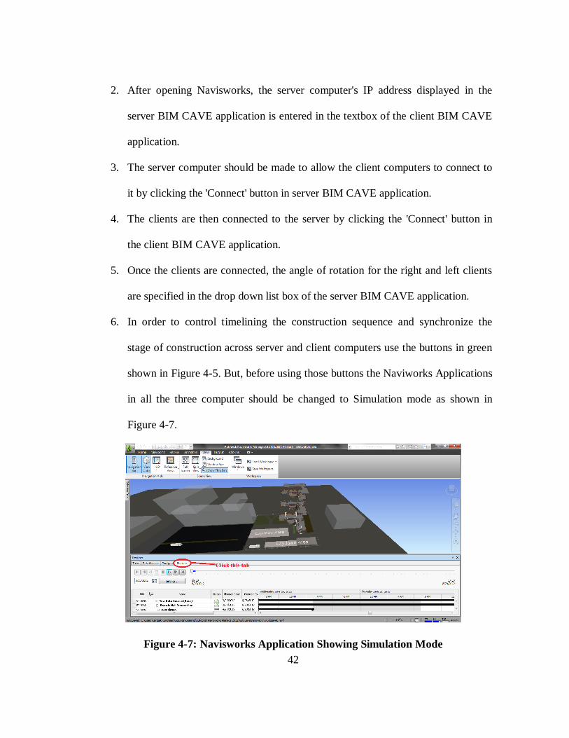
6. In order to control timelining the construction sequence and synchronize the
stage of construction across server and client computers use the buttons in green
shown in Figure 4-5. But, before using those buttons the Naviworks Applications
in all the three computer should be changed to Simulation mode as shown in
Figure 4-7.
Figure 4-7: Navisworks Application Showing Simulation Mode

43
4.2.2.4. Server-Client Algorithm
The same Server-Client algorithm written using .Net sockets in the previous BIM
CAVE application is used, through which the sever computer communicates with the
two clients (Left, and Right computer). The server application applies a mathematical
algorithm to the camera parameters of the Navisworks based on the configuration of the
screens and will send the calculated camera parameters and Timelining action performed
in the server application to the clients. The unique data packets for each of the clients
containing the camera attributes and the timelining action performed will be sent through
.Net sockets. The data transfer speed is highly crucial in the BIM CAVE, so the server
will send the data packets asynchronously, which means it will not wait for the client's
response after each and every transfer (Ganapathi 2012). This process is also
multithreaded in both the server and the client BIM CAVE application. The server
listens to the connection requests made by the clients in one thread and sends the data
packets to the connected clients in another thread simultaneously. Similarly, the client
will listen continuously to receive data packets from the server, which is handled by one
thread and processing of the data received is performed by another thread (Ganapathi
2012).

44
4.2.2.5. Navisworks API Algorithm
The Navisworks API algorithm deals with the interaction of the BIM CAVE
application and Navisworks (Ganapathi 2012). The API algorithm is different for the
server and the clients. C# programming language that was used to develop the BIM
CAVE application supports event driven programming. In other words, a certain set of
actions can be performed if a particular event is triggered. This process of event
triggering mechanism is used in the BIM CAVE application. Each button on server
application interface which controls timelining has been assigned to an Event Handler
which gets initiated whenever that button is clicked. This Event Handler executes a set
of functions which is called a method. This method executes the corresponding plugin
which controls timelining and updates the stage of construction in the running instance
of the Navisworks application. A number is generated corresponding to the button
pressed in the server application interface which is sent to the client application.
The BIM CAVE client application receives this number whenever a button which
controls timelining is pressed in the server application and it in-turn executes the
corresponding plugin in the running instance of Navisworks application in the client
computer to synchronize the stage of construction during timelining.

45
4.2.2.6. BIM CAVE Mechanism
The BIM CAVE application developed for this research integrates the hardware
and the software components to achieve an immersive virtual reality environment. The
BIM application executes the three algorithms Server-Client, Navisworks API and
Mathematical Rotation in a particular order to achieve a coherent view in all the three
walls. The following steps explain the working process of the BIM CAVE application
developed:
1. First, the Navisworks API algorithm is executed in the server BIM application.
The API algorithm will collect the camera parameters such as position, view
direction vector and up vector whenever the current view of the camera changes.
It also captures the button pressed (which control timelining) in the BIM CAVE
server application interface and assigns a number to it.
2. Once the server's camera parameters are generated, the mathematical rotation
algorithm will be applied to the gathered camera parameters and the axis and
angle of rotation for each of the clients will be calculated.
3. The Server-Client algorithm will be used to transfer the data packets containing
the axis, angle of rotation, and unique number generated corresponding to the
button pressed (which control timelining) in the BIM CAVE server application
interface to each of the clients connected with the server.
4. Clients receive the data packets sent by the server using the Server-Client
algorithm.
46
5. The received data packets will be used by the clients to update their camera
position with respect to the server and synchronize the stage of construction
during 4D construction sequence in order to achieve an immersive view using the
Navisworks API algorithm.
Figure 4-8 explains the working mechanism of the server and client BIM CAVE
application which has been developed previously and the additional functionality of
timelining which is added as a part of this research.
4.3. Challenges Faced
The .NET API documentation provided with the Autodesk Navisworks Manage
2012 did not release the classes which control timelining in Navisworks. There is no
documentation from the Autodesk for these classes because they did not want it to be
public. After going through the .dll assembly files which are installed along with the
Navisworks application, the class which controls timelining has been found.
“LcTISimulationHelper” is a class under the namespace
Autodesk.Navisworks.Api.Interop in the Autodesk.Navisworks.Timeliner assembly
which has the methods which control the Play, Pause, Stop, Step, ReverseStep,
ReversePlay, ReverseWind, and Wind buttons of the Timelining animation. Only Step,
Stop, and Reverse Step methods have been used for this research.
But, these methods could not be used directly in the Server or Client application
to control timelining in Navisworks application as Autodesk did not release them to be

47
Figure 4-8: Working of New BIM CAVE
Trigger Event when Camera View Changes
Obtain Camera Parameters
Calculate Camera Parameters for Clients
Send Data Packets to Clients
Receive Data Packets
Apply the Received Camera Parameters
Trigger Event when Timeliner Button Clicked
Execute Corresponding Plugin
Generate a Number Corresponding to the Plugin
executed
Send Data Packets to Client
Receive Data Packets
Execute Corresponding Plugin in Client Navisworks
Application
Server Application
Client Application
Server Application
Client Application
Previous BIM CAVE
Application
Additional Timelining
Functionality
New BIM CAVE Application

48
used in Automation. So, Plugins for each of the methods had to be developed which in-
turn were executed through Automation whenever the corresponding button is clicked in
the server application interface.
As this information was not readily available at hand, a lot of time was spent on
trials, and debugging. After contacting the Autodesk Developer Consultant these issues
were recognized and a way around was discovered to gain control over the timelining in
Navisworks Manage 2012.
49
CHAPTER V
DATA COLLECTION
The research methodology employed to validate the new BIM CAVE application
developed as a part of this research is Phenomenological Study. The interviews were
videotaped so that the videos could later be transcribed and analyzed to understand the
SME’s perception about its effectiveness. Videotaping also helped in making the
interview process flow smooth without interruptions and allowed the interviewer focus
more on questions that could be asked to get as much information from the interviewee
as possible.
A typical sample size for a Phenomenological study is from 5 to 25 individuals,
all of whom have had direct experience with the phenomena being studied (Creswell
1998). Six participants were interviewed who were professionals from the AEC industry
with experience in BIM, virtual reality systems, and project planning. The six
participants of this study are a BIM Manager, a Project Manager, a Senior Project
Manager, a Senior Vice President, a Project Manager, and a Senior Industry Manager
representing different companies. In order to protect the privacy of the participants, their
identities were not revealed and were mentioned as Interviewee 1, 2, 3, 4, 5, and 6.
Since, the results from this study is based on the feedback given by the six participants,
their credibility is a major factor for obtaining reliable results.

50
The qualifications of the participants of this study are as follows:
1. BIM Manager
Interviewee 1 has about five years of experience in the construction industry with
BIM, BIM based estimating, and model based scheduling.
2. Project Manager
Interviewee 2 has about fifteen years of construction experience in project
management, estimation, and architecture. He has acquired skills to coordinate the
pre-construction phase of any project with good appreciation for the concepts of
BIM.
3. Senior Project Manager
Interviewee 3 has about ten years of construction experience in project
management, estimation, architecture, and facility services. He has extensive
experience in using BIM for design, and maintenance of facilities.
4. Senior Vice President
Interviewee 4 has about thirty years of experience in design and construction. He
is responsible for corporate technical services which include BIM and innovative
in-house software developed for project management at a General Contracting
company. He has extensive experience in project management, project controls,
and estimation.

51
5. Project Manager
Interviewee 5 has about sixteen years of experience in project management,
construction automation, project planning, estimation, and scheduling. He
extensively used BIM on many of his projects.
6. Senior Industry Manager
Interviewee 6 has about seventeen years of experience in project management,
estimating, project controls, and development of construction software. He
provides services to clients on BIM and bridges the gap between the industry and
software development for project management. Interviewee 8 has extensive
experience in advanced visualization techniques and its applicability to
construction.
The following questions were asked by the researcher to the SMEs during the
interview sessions:
1. Describe your experience of timelining in BIM CAVE?
2. What kind of construction decision can be made with ease from your experience of
timelining in BIM CAVE compared to experiencing timelining on a single screen?
3. What are the advantages and disadvantages of timelining in BIM CAVE?
The interview questions helped to know the participant’s opinion about the
effectiveness of timelining in BIM CAVE and its value addition over visualizing
timelining on a single screen. It also facilitated to understand the various applications of
timelining in BIM CAVE to the construction processes. The benefits and limitations of
timelining in BIM CAVE were also obtained from the participants as a part of the

52
interview process. Appendix-A contains the transcripts of the six interviews conducted.
The following chapter discusses the results of the phenomenological study.

53
CHAPTER VI
RESULTS
The video tapes of the interviews were used to transcribe the statements of the
interviewees and the data was analyzed to understand the effectiveness of timelining the
construction sequence in BIM CAVE using the new BIM CAVE application. This
section shows the findings of the interviews, which helped identify the value addition,
benefits, and limitations of visualizing 4D construction sequence in BIM CAVE
compared to visualizing 4D construction on a single desktop screen.
The interview transcripts were analyzed and grouped based on the following
three topics of interest:
1. The experience of visualizing timelining of 4D construction in BIM CAVE
compared to visualizing 4D construction on a single screen.
2. Benefits of timelining the 4D construction sequence in BIM CAVE compared to
4D visualization on a single screen.
3. Limitations of the new BIM CAVE application.
6.1. BIM CAVE for 4D Construction Experience
The participants were given a demonstration of how the setup works and were
allowed to use the BIM CAVE to experience it by themselves. After the system
introduction phase, the participants were asked about the experience of timelining the 4D

54
construction sequence in BIM CAVE. They were also asked to describe the difference
between visualizing the 4D construction in BIM CAVE and on single screen.
Interviewee 1, BIM Manager, described that 4D visualization in BIM CAVE
gives a different perspective. The participant explained that when 4D models are viewed
on a single screen they look it from a bird’s eye view or a perspective outside the project
so that they can see everything going on in the project. The Participant mentioned that
the interesting thing with BIM CAVE is that it is possible to sit inside the building and
see things being built around you as they would be in the actual construction
environment. It also gives a perspective greater than the things going on right in-front of
the participant and helps in identifying issues such as how the construction sequence at
one place affects construction sequence at another place adjacent to the later one.
Interviewee 2, Project Manager, described timelining in BIM CAVE as an
excellent tool as it helps to keep the project on schedule. It helps to immediately identify
when the project starts to fall behind the schedule and how each task affects it. The
participant mentioned it to be a useful tool in project planning.
Interviewee 3, Senior Project Manager, described timelining in BIM CAVE to
have a wow factor on the users and helps them try different options of designing an
element based on the feasibility of construction and within cost. The participant
mentioned that being able to sit inside building and walkthrough different construction
phases helps them to convey their ideas in a more realistic spatial perception.
Interviewee 4, Senior Vice President, said that people are visual learners.
Describing any system to a person in words or in writing takes long time for the brain to

55
process the information and understand the system. Whereas visual representation helps
people understand the system immediately. The participant mentioned that more the
visualization (such as BIM CAVE) introduced into the process the easier and faster it is
for a person to understand the message which is in this case construction schedule.
Interviewee 5, Project Manager, described the this research to be the right
concept as bringing timelining into BIM CAVE gives a better spatial perception of
things during construction and be able to visualize them in real scale perspective as to
the status of the project. The participant also mentioned that it is very critical in making
sure that the users get the most effective and efficient construction sequence.
Interviewee 6, Senior Industry Manager, described that this system gives a better
sense and more realistic view of what is going on around the user during the 4D
construction sequence. The participant mentioned that it is hard to overstate the amount
of value that will come from immersing people in the model during 4D construction
sequence before they build it on the field.
6.2. Benefits of Timelining 4D Construction Sequence in BIM CAVE
Interviews with the industry professionals in the AEC industry revealed the
potential benefits of visualizing timelining of 4D construction sequence in BIM CAVE
over the 4D construction sequence on a single screen. The advantages of timelining in
BIM CAVE as described by the participants can be summed up as follows:

56
Enhanced confidence in the decisions made over the sequencing of the activities
in a construction schedule.
Better communication of construction schedule to the project stakeholders to
keep them on same page.
Better sequencing of construction activities due to better spatial perception.
Better plan parallel activities due to better spatial perception and effectively
compress the duration on the construction schedule.
Resolve constructability issues in a collaborative way by discussing and
resolving conflict issues with other trades before building it on field.
Helps in better defining the installation path for equipment used to install
building elements and use them efficiently.
Training the construction work force.
Good marketing and sales tool when interviewing with an owner for a project.
Interviewee 1 stated that timelining in BIM CAVE helps in making more
informed decisions as it gives a perspective of how construction sequencing at one place
affects the construction sequence at the other place. The participant mentioned that it
gives a lot more confidence and justification as to why a certain decision has been taken.
“There is more evidence behind this is why I decided to start that activity here and
worked through to here. You have a lot better justification for the decision you have
made.” The participant also stated that timelining in BIM CAVE distinguishes a
company from another company interviewing for the same project. It can be used as a
good sales and marketing tool.

57
Interviewee 2 expressed that timelining in BIM CAVE helps them as an architect
to better communicate with contractors as to how a particular idea is going to work out,
and how it will be constructed. Architects can also get the feedback from the contractor
if contractor suggests an alternative design for efficient constructability. The participant
mentioned that timelining in BIM CAVE saves a lot of communication gaps and helps
better communicate ideas to all the project stakeholders.
Interviewee 3 mentioned that timelining in BIM CAVE helps better phase the
project to decide on which discipline needs to be on the site at one particular time. The
participant stated it can be used for better construction sequencing when different
subcontractors collaboratively visualize the 4D construction sequence in BIM CAVE
before actually going on filed and performing the job. This helps in avoiding
interference between trades.
Interviewee 4 mentioned that the more and more a person gets immersed in a
virtual environment the faster they acquire the knowledge. The participant quoted that
“The subcontractors are two generations back as they are still looking at paper drawings
to understand stuff and now when we tell them you can visualize this stuff and as we
bring multiple disciplines and subs into the CAVE, they build it in their brain first about
what the construction complexities would be and solve them in BIM CAVE. When they
go out in field they can build it much quicker on field which means a lot of profit for
them.”
Interviewee 5 stated that this system helps to verify and confirm if the sequence
is right, most effective, and efficient. It helps users consider many options and select the

58
option which is more efficient and productive. The participant quoted “In rigging where
you have got heavy rigs come in and place heavy equipment stuff the installation path
and sequencing is ensured and helps you utilize your cranes most effectively.” He also
quoted “It is one that you bring in all your different stakeholders in the project. You get
them all in the same room at the same time. They are all seeing the same thing and they
now start focusing on what they are responsible for doing and they start bringing up
things because they see what everybody else is doing at the same time. And they bring
up a problem saying I am going to be working here and I am not going to allow you in
this area while I am working because of safety and practicality and things like that.
These things start coming on to the surface early in the project so that adjustments can
be made so that the efficiency of the overall project can be raised.”
Interviewee 6 quoted “This also helps them to get different motion paths to do
the same task more efficiently. If I am a contractor and when I show up at an interview
with a thing fold out and show 3D model in BIM CAVE getting owner to go through the
presentation, it would win you a project.” The participant stated that timelining in BIM
CAVE helps micro-sequencing of all the tasks faster compared to visualization on single
screen. He also quoted “On the other hand it might bring up new issues which the
coordinator might not have visualized. It makes people more engaging.”
59
6.3. Limitations of the New BIM CAVE Application
The SMEs also explained their opinion about the limitations of the suggested
new application. The summary of the limitations obtained from the interview transcripts
is as follows.
The current BIM CAVE system is not compact and mobile.
Not being able to synchronize the hiding of elements across all the three
computers of BIM CAVE.
During coordination meetings it is difficult to keep people look at the same issue
being discussed.
Bird’s eye view of 4D construction sequence better in the initial stage of the
project.
Interviewee 1 mentioned that during coordination meetings it would be difficult
to keep people focus on the same issue which is being resolved before moving on to the
next issue. As different people look at different screens it is hard to make them
concentrate on one particular issue. The participant also stated it would be resolved if we
could switch of other walls and make them concentrate on one particular issue. He also
quoted “Projectors in a room of a conference setting would be more applicable to the
construction industry”, stressing on the BIM CAVE system to be more compact and
easily movable.
Interviewee 4 quoted “I personally like when you can make certain elements of a
building transparent. So that you might say the majority of what is going on is behind
that wall so can you make that wall transparent so that I can see the essence of what I am

60
trying to understand. When we do this with clients and architects in office, they always
want something different turned on and off because everybody is looking at it slightly
different. So the more you can make the tool adaptable to any possible user the more
beneficial it would become.”
Interviewee 5 stated that during initial stages of project he preferred bird’s eye
view of the project to see the overall picture of everything that is going on. He quoted
“In early planning phases and study of the project you really need to see the big picture
of where everything is taking place in the project. So you can get your man power
loading spread out across the project. You can potentially address all the work fronts you
have.”
Interviewee 6 stated that making the timelining in BIM CAVE more interactive
and easy enough for people who are not technical to interact with. He quoted “I think
idea of getting into touch screen to fix things together and changing the sequencing
while I am here touching the screens would be more interactive.” He also raised the
issue of keeping all the participant concentrate on the same issue. He quoted “One
person might be looking here and some other person might be looking somewhere else
and so it might be a challenge to make all the team to look at one issue.”

61
CHAPTER VII
CONCLUSION
This section provides a summary of this research that briefly explains the
research problem, motivations, and findings. Then, recommendations for future research
are presented.
7.1. Research Summary
The previous BIM CAVE version had limitations in terms of synchronizing the
4D construction sequence which resulted in loss of immersion during the simulation
process. To overcome the problem of visualizing timelining in the existing BIM CAVE,
a new BIM CAVE has been developed to synchronize the 4D construction across all the
three computers in the BIM CAVE system. This research used the existing BIM CAVE
hardware which used the new BIM CAVE application. The BIM CAVE setup was then
validated using qualitative research methodology. Qualitative methodology involved
conducting descriptive interviews with SMEs. The interviews revealed that timelining in
BIM CAVE makes the visualization process of 4D construction sequence more effective
than visualizing 4D construction sequence on a single screen as it gave a better sense of
spatial perception of the space in the building and accommodates many project
stakeholders who can collaboratively resolve construction related issues compared to
single desktop screen. Timelining in BIM CAVE has several other advantages such as
62
getting to know how construction sequence in one place affects the construction
sequence in a space adjacent to it, effective communication of the construction schedule
to all the project participants, collaboration between trades to resolve issues related to
space interference before going on site, defining the installation path and sequence of
building elements using heavy equipment with much more confidence and justification,
and training the workforce. As a conclusion, with some limitations the SME’s
evaluations of the BIM CAVE prototype provide evidence that the 4D visualization in
immersive virtual environments such as BIM CAVE is effective compared to 4D
visualization on a single desktop screen.
7.2. Future research
Considering all the suggestions from the participants, the researcher puts forth
the following recommendations for future research:
1. Screens with projectors can be used to make the BIM CAVE hardware more
compact and mobile.
2. Some of the other features of Navisworks such as hiding model elements, and
other model manipulation functions can be synchronized between the server and
client computers in the BIM CAVE.
3. Ability to turn off the BIM CAVE system and reverting back to single screen
system.

63
4. Testing the advantages of timelining in BIM CAVE discovered during this
research individually to quantitatively analyze the benefits.
5. Testing the possibility of using commercially available software other than
Navisworks in the BIM CAVE system.

64
REFERENCES
Autodesk Incorporation. March 2010. Navisworks 2011 .NET API Developer’s Guide.
Biocca, F., and Levy, M.R. (1995). Communication in the Age of Virtual Reality,
Routledge, New York.
Bouchlaghem, D., Shang, H., Whyte, J., and Ganah, A. (2005). “Visualisation in
architecture, engineering and construction (AEC)." Automation in Construction,
14(3), 287-295.
Bricken, M., and Byrne, C. (1993). Students in Virtual Reality: A Pilot Study. In Alen
Wexelblat (Ed.), Virtual reality: Applications and explorations (pp. 246-273),
Academic Press, San Diego, CA.
Cleveland, A.B., Jr. (1989). “Real-Time animation of construction activities.”
Proceedings of Construction Congress I – Excellence in the Constructed Project,
American Society of Civil Engineers, San Francisco, CA.
Creswell, J. W. (1998). Qualitative Inquiry and Research Design: Choosing Among Five
Traditions, Sage Publications Thousand Oaks, CA.
Cruz-Neira, C., Sandin, D.J., and DeFanti, T.A. (1993). “Surround-screen projection-
based virtual reality: the design and implementation of the CAVE.” Proceedings of
the 20th Annual Conference on Computer Graphics and Interactive Techniques, ser.
SIGGRAPH '93, New York, NY, USA. 135-142.
DeFanti, T.A., Dawe, G., Sandin, D.J., Schulze, J.P., Otto, P., Girado, J., Kuester, F.,
Smarr, F., and Rao, R. (2009). “The StarCAVE, a third-generation CAVE and virtual
reality OptIPortal." Future Generation Computer Systems, 25(2), 169-178.
Ganapathi, A. (2012). “Immersive virtual reality system using BIM application with
extended vertical field of view.” M.S. Thesis, Dept. of Civil Engineering, Texas
A&M University, College Station, TX.
Gopinath, R. (2004). “Immersive virtual facility prototyping for design and construction
process visualization," Ph.D. dissertation, The Pennsylvania State University,
University Park, PA.
Hatada, T., Sakata, H., and Kusaka, H. (1980). “Psychophysical analysis of the sensation
of reality induced by a visual wide field display." Smpte Journal, 89(8), 560-569.

65
Issa, R.A. (1999). State of the Art Report: Virtual Reality in Construction, International
Council for Research and Innovation in Building and Construction (CIB),
Rotterdam, Netherlands.
Kasik, D., Troy, J., Amorosi, S., Murray, M. and Swamy, S. (2002). “Evaluating
graphics displays for complex 3D models.” Graphics in Advanced Computer-Aided
Design, 22(3), 56-64.
Koo, B., and Fischer, M. (2000). “Feasibility study of 4D CAD in commercial
construction.” Journal of Construction Engineering and Management, 126(4), 251-
260.
Kozma, R., and Shank, P. (1998). Connecting with the twenty first century: Technology
in support of educational reform, American Society for Curriculum Development,
Washington, DC.
Kumi, A., and Retik, A. (1997). “Library-based 4D visualization of construction
processes.” Proceedings of the Information Visualization Conference; IEEE,
Piscataway, NJ, 315-321.
Kvale, S. (1996). Interviews: An Introduction to Qualitative Research Interviewing,
Sage Publications, Thousand Oaks, CA.
Leedy, P. D., and Ormrod, J. E. (2005). Practical Research: Planning and Design,
Prentice Hall, River, NJ.
McKinney, K., and Fischer, M. (1997). "4D Analysis of Temporary Support."
Proceedings of the Fourth Congress on Computing in Civil Engineering,
Philadelphia, PA, 470-476.
McMillan, J.H., and Schumacher, S. (2001). Research in Education, 7th Ed., Pearson,
New York.
NBIMS. (2007). "National BIM standard | whole building design guide."
<http://www.wbdg.org/bim/nbims.php> (03/30, 2013).
Psotka, J. (1995). “Immersive training systems: Virtual reality and education and
Training." Instructional Science, 23(5), 405-431.
Reeth, F., Claes, J. and Flerackers, E., (1995). “Advanced motion specification and
stereoscopic visualization on a PC-based modeling environment.” Conference
Proceedings – Second International Conference on Visualization and Intelligent
Design in Engineering and Architecture, Southhampton, UK, 43-50.

66
Rheingold, H. (1993). Virtual Reality, Summit, New York, NY.
Rischmoller, L., Fischer, M., Fox, R., and Alarcon, L. (2001). “4D Planning and
Scheduling (4D-PS): Grounding Construction IT Research in Industry Practice.”
Conference Proceedings- IT in Construction in Africa, CIB W78 International
Conference, Mpumalanga, South Africa, 29 May – 01 June.
Shaw, T. (2002). “Applied Research Lab at Penn State University, Synthetic
Environment Applications Lab (SEA Lab).” May7,
(www.arl.psu.edu/faclities/facilities/sea_lab/sealab.html), Accessed: Jan. 15, 2013.
Simons, K.L., and Thornberry, H.L. (1988). “Simulation system for construction
planning and scheduling.” Joint ASME/IEEE Power Generation Conference,
Philadelphia, PA, ASME, New York, NY.
Whisker, V., Baratta, A., Yerrapathruni, S., Messner, J., Shaw, T., Warren, M., Rotthoff,
E., Winters, J., Clelland, J., Johnson, F. (2003). "Using immersive virtual
environments to develop and visualize construction schedules for advanced nuclear
power plants." Proc., 2003 International Congress on Advances in Nuclear Power
Plants (ICAPP), Córdoba, Spain, 1-7.
Yerrapathruni, S. (2003). “Using 4 D CAD and immersive virtual environments to
improve construction planning.” M.S. Thesis, Dept. of Architectural Engineering,
The Pennsylvania State University, University Park, PA.

67
APPENDIX A
INTERVIEW TRANSCRIPTS
INTERVIEW-1
Interviewer
Can you please explain your experience of timelining in BIM CAVE? How is it like to
view 4D construction in a multi-screen environment like BIM CAVE?
Interviewee-1
“It definitely gives you a different perspective. Historically when we do a timeliner or
animation in Naviswork we look it from a bird’s eye view or a perspective outside a
project so that you can see everything that is going on. The interesting thing with BIM
CAVE is you can sit inside the building and you can see things built around you as they
would be built in the actual construction environment in the field. You would be seeing
it as people on the field will be seeing it going up.”
Interviewer
That is a good perspective. Can you elaborate the difference between taking a look at the
project from a bird’s eye view vs taking a look at the project sitting within the building?
I guess you get a lot of information from looking at 3D model from Bird’s eye view.
But, if you have a chance to get into the building looking at entire processes going on
around you, what additional decisions or benefits you can make or get from being able to
do that? Just assume you are surrounded by 3D model evolving as time goes by and if
68
you are looking at the model for making decisions, what decisions you think you could
possibly make additionally?
Interviewee-1
“It is interesting that you are able to actually see more than what’s just going on right in
front of you. One of the things may be not so much on the timeliner but when you start
doing clash detection, if you are only looking at what is right in-front of you, you may
not have an understanding of how this is going to affect something right here to
something at 90 degrees out of your vision. Being able to see everything surround you
and how making a change in this construction sequence over here is going to affect
something over there I think may be is helpful.”
Interviewer
Let us say you are able to see those some changes around you more intuitively.
Interviewee-1
“Yes. You really get a better feel for what is going on around you. Not only you are
looking ahead but then you also understand the work I have got going on over here and
over here and how that’s all affect each other.”
Interviewer
Do you think you can make different decisions from being able to see that or do you
think you can make the same decision more effectively from doing 4D construction in
BIM CAVE. It is all about making informed decisions. We would like to see how
differently you can make the same decision or you can make even different decisions
from 4D construction in BIM CAVE.

69
Interviewee-1
“I think you may be making a more informed decision. I think you get a better
understanding of what is going on around you. You get to be able to make may be the
same decision. You may still get from point A to point B the same way but you have a
lot more confidence in your decision that you have made. There is more evidence behind
this is why I decided to start that activity here and worked through to here. You have a
lot better justification for the decision you have made.”
Interviewer
So do you think this will help in improving your schedule?
Interviewee-1
“Absolutely! Being able to visualize things before they happen in the field and spending
time on the model upfront is always better than having to reschedule things in the field.
So having that understanding of how everything goes together upfront is a crucial part of
our scheduling logic process.”
Interviewer
Any more advantages you see compared to timelining on single screen?
Interviewee-1
“I think it does have a lot of things going for like being able to see things around you.
But, in the same instance it also can be distracting. If you want to focus on something
and you have six other screens or another 180 degree vision, people may get distracted.
We have got to see how that works out because you may be want to focus on just this
area of the building but if I got people in the room looking at the other 180 degree of

70
vision they definitely get distracted. I have run into such situations sometimes in
meetings. That will be interesting challenge to see how that works out. Keeping them on
same page is difficult.”
Interviewer
You mentioned you use 4D construction sequence in your coordination meetings, do you
have any challenges in terms of using 4D construction model or in terms of creating 4D
model?
Interviewee-1
“The biggest is that it is getting people to think in the 4D mindset and one of the other
things we are trying to do is get away from the traditional CPM activity based
scheduling and moving more towards a flow line or location based schedule. And
making that transition is definitely the biggest challenge we have got because every
contractor you see has CPM verbage in their contracts. But, getting exactly how many
men I need to have in this location on this day to complete this activity in this amount of
time and creating a flow through the project based on the location system is a much
more efficient system than the schedule that we have traditionally been using.”
Interviewer
Can you please suggest some improvements to the application so that timelining can be
visualized better?
Interviewee-1
“One of the good features would be to sync up what you can see and what you don’t
want to see. Being able to turn of things in your selection tree and reciprocate throughout

71
the model or possibly having a really easy way to turn of the other screens so that
everybody is on the same page and pay attention to single issue when things are getting
out of control to get out of the CAVE environment. I definitely think it has some
advantages in the timeliner end and clash detection being able to see things in a greater
perspective. Projectors in a room of a conference setting would be more applicable to the
construction industry.”
Interviewer
What other non-construction related advantages do you think are possible with BIM
CAVE?
Interviewee-1
“Outside of construction sequencing advantage it can also be used as a sales tool. You
are offering something that someone else may not be able to offer. It is a good marketing
tool as people want to come to see your BIM CAVE and have their meetings in the
company as they can get in the model to really understand what is going on.”
INTERVIEW-2
Interviewer
Can you describe your experience of timelining in BIM CAVE?
Interviewee-2
“As far as timelining I have never used it for timelining but it is an excellent tool. It is a
tremendous tool to keep the project on schedule. You immediately know when you start
to fall behind on any particular task. So I think it will be very useful.”

72
Interviewer
If you had a chance to use 4D visualization in an environment like this how would you
like to use this system to enhance your decision making process during preconstruction
coordination process or design process within your company?
Interviewee-2
“Using it with the design process we are able to get in there and see it 3Dimensionally.
Otherwise you kind of visualize in your mind when you are looking at 2D drawings and
stuff. Being 3D enabled you get the actual idea and then you know how is that particular
idea is going to work out, how are you going to construct which gives you a basic idea of
what it is going to take. Being able to show it to the contractor that there exists a certain
area and this is the way it needs to be done, this is the affect and the look that we are
going for.”
Interviewer
How about working with the project owners asking you to design certain things? How
do you think showing the phases of construction in BIM CAVE benefit you and the
owner?
Interviewee-2
“It would put everybody on the same page. We are always discussing ideas with people.
People interpret ideas differently. When you are able to put it down let the owner see it
and say this is what you are thinking. And if not then you can make any tweaks that you
need and if not you can stay with it when he says it is exactly what he wanted. It solves a
lot of communication gaps and communication of ideas.”

73
Interviewer
As you have mentioned you have been using visual representation of your project to get
the construction owner in the same page with you, I guess you were using single screen
to explain the owners what you have designed and see if they like it. What you can do
with this BIM CAVE system is that you can bring the owners into the building and show
him the space he will be occupying. Let us assume you are capable of doing that and
what benefits do you expect from doing it?
Interviewee-2
“By doing that what it does is it will allow people to walk into the building. You want
people to walk in and if you have an element that you are trying to really make enhance
the project, you can show that to them and then get the wow factor for what the owner is
looking for or what he is trying to emphasize in his building. By having a walkthrough
the building it shows exactly how it is laid out and as he walks through he may realize to
change something or switch something around which gives us that opportunity at that
time as well. But, being able to actually sit there and walk through the building before it
is constructed will save a lot in change orders and things like that that happen during
construction.”
INTERVIEW-3
Interviewer
Can you please describe your experience of visualizing 4D construction in BIM CAVE?
Interviewee-3

74
“I have personal experience for myself and it is a blossoming thing in our office. The 4D
aspect of time is something that we are venturing into right now with several different
consultants. S&P and Spaw Glass but were using it more and more for construction cost
analysis. Different options for whether we use this type of metal stud or that type of rigid
framing to show the owner the differences in feasibility of construction and more
important to them is cost as cost is derived from time. But it is in its infancy in our firm
and in infancy nationwide. People are developing different ways of reporting on it. And
we are learning more and more about the way to properly Revit families so that they can
be reported upon certain families and other families may not give the information that
you are looking for. So it is a trial by fire right now.”
Interviewer
Is viewing 4D construction in multiple screens better than compared to viewing 4D
construction sequence on single screen?
Interviewee-3
“I think it certainly has a lot more wow factor to it to have a full surround immersion of
the space that you are in. It certainly is neat and being an architect and being in the
industry I am capable of visualizing things just by nature. But, obviously owners are not
capable of conveying anything on a piece of paper or possibly not sure what is going on
in their mind. So being in an environment which allows them to be as close to reality, I
would imagine would be much better way to convey exactly what is going on in kind of
a more realistic spatial way.”
Interviewer
75
From your experience how does 4D construction sequence in BIM CAVE help you in
making your decisions better?
Interviewee-3
“The ability to time sequence what is going on in construction and I am not certain if it
helps a person that is possibly mentally handicapped on trying to figure of sequencing of
a project or if it finds errors or it is easier or if the architectural profession is using too
many crutches to successfully complete their projects. I know there must have been
smart enough architects before us. They figured out a lot of things but may be they did
figure them out with a lot of cuts and dents along the way. So in my professional
experience, I am currently working on things that involve a foundation, that involve
sequencing of plumbing going in before certain areas of foundation need to go when.
And extremely worried about project phasing to which of the different disciplines need
to be on the site at one particular time. When you get your concrete person out there you
want him to stay. But, you might have another portion of the project which is more
complicated and in different phase but being able to take a look at the construction
sequencing and understanding which materials need to be placed first, certainly could
keep you out of needing to break up some concrete later.”
Interviewer
What are the advantages and disadvantages of 4D construction in BIM CAVE?
Interviewee-3
“The advantage is foregoing a lot of time headache and costs change orders and things
that keep getting you in a law suit. It is paramount and so the ability to sit down and

76
coordinate with contractors who in many cases are incapable of visualizing things in 3D,
or read blue prints, and possibly there are architects who are incapable of displaying
their intents in a set of blue prints can easily display In the BIM environment and the 4D
sequencing scenarios, many things can be discussed in advanced that cannot be easily
visually conveyed.”
INTERVIEW-4
Interviewer
Can you please describe your experience of visualizing 4D construction in BIM CAVE?
Interviewee-4
“I have used it pretty extensively over the years with some of our clients on CMAR
projects and projects where we were providing control services to the owner. People are
visual learners. You can just describe the system and it takes the brain a long time to
process that information and understand and form that picture in a person’s mind.
Whereas if you see it, you immediately understand it. So the more the visualization
introduced into the process the easier and faster it is for a person to understand what the
message is.”
Interviewer
You mentioned you use BIM in your projects. For what purposes do you use BIM in
your project?
Interviewee-4

77
“We use it for various things. Our biggest project is a billion dollar project in New York.
We integrated actually to the schedule and to the cost of the project. So, then by doing
that early finish and late finish on a CPM now we begin to not only understand where
the project is but we can visualize the exact the elements of the building that are either
ahead of the schedule or behind schedule. By doing that its incredibly powerful because
not all parts of the building are created equal. If you have a part of a building such as
mechanical room and that’s falling behind schedule. That has more of an impact on
construction project than an activity that doesn’t have much of an impact on the project.
And so by integrating all of that information we have a pretty powerful tool to visualize
the implications.”
Interviewer
How does timelining in BIM CAVE different from timelining on a single screen and
does it help you in better making your decisions?
Interviewee-4
“Yeah I guess I would kind of say like this. In the old world we used 2D drawings and
so your brain had to somehow convert that 2D information into a 3D image before you
could start to react to the information. Then you of course had to tie it to other things like
finish schedules and all other things that make up the building. When you went to one
screen visualization that was a monumental leap in understanding what you are looking
at. Now when you got to 3D visualization it is that same next step in the process. So it is
kind of incremental evolution trying to create in essence to real world. You are trying to
create the real world in a cyber-world. So the more and more 3D you become in that

78
more you can immerse a person in a real 3D environment the faster they acquire
knowledge.”
Interviewer
Do you have any suggestions to improve the application or any additional functions to
make the visualization better?
Interviewee-4
“I personally like when you can make certain elements of a building transparent. So that
you might say the majority of what is going on is behind that wall so can you make that
wall transparent so that I can see the essence of what I am trying to understand. When
we do this with clients and architects in office, they always want something different
turned on and off because everybody is looking at it slightly different. So the more you
can make the tool adaptable to any possible user the more beneficial it would become.”
Interviewer
What do you think about the communication between trades when they are visualizing
4D construction in BIM CAVE?
Interviewee-4
“Because we are doing this real world up in JFK a billion dollar project and when we
bring the trades in BIM CAVE what we have found is that the trades people or the subs
like it because they are not used to this at all. They are 2 generations back as they are
still looking at paper drawings to understand stuff and now when we tell them you can
visualize this stuff and as we bring multiple disciplines and subs into the CAVE, they
build it in their brain first about what the construction complexities would be and solve

79
them in BIM CAVE. When they go out in field they can build it much quicker on field
which means a lot of profit for them.”
Interviewer
If you had a BIM CAVE system like this for your project what would you like to use it
for?
Interviewee-4
“I am kind of a visualization junkie. I am always pushing it at our company and I am
pushing it with our owners because of what I said before. It comes down to that cooler
concept that is human beings are visual learners. We exist in a 3D environment and our
brains have been coded. The thing I like about it is the more real it becomes the more 3D
it becomes and the human brain process it fast and there will be a time when I think will
exist in holographic world.”
INTERVIEW-5
Interviewer
What do you think about this BIM CAVE system?
Interviewee-5
“You guys have got the right concept behind being able to bring in the project models to
be able to turn them on in a timeline as to when and where they are going to be. Even
verify and confirm if you have got the right sequence or the most effective and efficient
sequence. More than one way to put things in and you are sure you are doing things most

80
effectively and get the most productivity out of the project. It is very critical that you are
able to bring all this together.”
Interviewer
How do you think 4D construction visualization in BIM CAVE different from 4D
construction visualization on single screen? How does it help in decision making?
Interviewee-5
“Honestly when I do a 4D construction simulation I prefer a bird’s eye view and in some
cases you get to see the overall picture of everything that is going on. In early planning
phases and study of the project you really need to see the big picture of where everything
is taking place in the project. So you can get your man power loading spread out across
the project. You can potentially address all the work fronts you have. If you get in and
zoom too close you are going to mess up. Rigging where you have got heavy rigs come
in and place heavy equipment stuff the sequencing is ensuring that you are utilizing your
cranes most effectively. I know there was a multi-billion dollar project where several
units were all going in at the same time with all kinds of lifts going on. By having a look
at the 4D construction sequence of all the activities coming into play and everything
being lifted, it was evaluated and by just changing the lifting logs of equipment a week
here and week there determining when to lift these heavy pieces and equipment, they
were able to eliminate the need for 4 different heavy lift cranes. It resulted in tremendous
amounts of savings as instead of using 4 different cranes at the same time they were able
to use a single crane and by moving them around and sequencing the activities.”
Interviewer

81
So do you think it can be used for schedule improvement and make the schedule more
efficient?
Interviewee-5
“Definitely, it is one that you bring in all your different stakeholders in the project. Your
contractors, owners, EPC, and engineering departments. You get them all in the same
room at the same time. They are all seeing the same thing and they now start focusing on
what they are responsible for doing and they start bringing up things because they see
what everybody else is doing at the same time. And they bring up a problem saying I am
going to be working here and I am not going to allow you in this area while I am
working because of safety and practicality and things like that. These things start coming
on to the surface early in the project so that adjustments can be made so that the
efficiency of the overall project can be raised.”
Interviewer
Anything you would like to add which I didn’t ask you?
Interviewee-5
“Projects that are going to use it are going to be further ahead than the projects that are
not going to use it.”
INTERVIEW-6
Interviewer
Can you please summarize your experience of timelining in BIM CAVE?
Interviewee-6

82
“There is so much to be learnt in the interface between the academia and industry and
our customers are the right ones to be with you. I have seen customers now go from,
even 5 to 6 years ago they did not know what BIM is and that’s a kind of a toy to show
pretty pictures to the owners to get the job and throw it away and draw something.
Today the customers are really seeing the value of driving that level of understanding.
Not only for their customers but owner, and people that they are selling to and also to
express to the public. Trying to get the people who are going to do those tasks to
understand the project better in virtual space the first time. I see this not only as an
opportunity for contractors but also building maintenance people downstream to be able
to really experience the building interact with that and also to the people who are
actually installing the elements to see how things are going to fit together. This also
helps them to get different motion paths to do the same task more efficiently. Now the
challenge is not the capability of the software to do certain things but it is getting those
things to be easy enough for people who are not technical to interact with. So as I sit
here with your screens behind me, imagine what if there is a Microsoft connect device
where I could somehow use my hands to manipulate my view more intuitive than to run
a mouse or perhaps what if these were touch screen tv’s. Then i could literally in this
environment marking things up in real time and even in such a way that people
somewhere else kind of have the same experience I am having and let me show them
what I am talking about remotely. If we are running the software of the cloud then
perhaps we could actually bring people together without co-locating them. Customers
have great reaction to this and I know customers are investing a lot of money in BIM

83
CAVE. Customers are also using it at the project level but if we can somehow get it to a
one box and few video cards then even these 3 tv’s it is just fantastic compared to the
two dimensional view on one screen. You get a lot better sense of what is towards my
left or right. Portability is a big advantage. If I am a contractor and when I show up at an
interview with a thing fold out and show 3D model in BIM CAVE getting owner to go
through the presentation, it would win you a project. Getting back to trades people it is
hard to overstate the amount of value that will come from immersing people in the
model before they go do it. But it is got to be drop dead easy and got to be interactive to
evaluate what if scenarios and change things. I think idea of getting into touch screen to
fix things together and changing the sequencing while I am here touching the screens.”
Interviewer
From your experience how do you think 4D construction sequence in BIM CAVE help
them in better decision making?
Interviewee-6
“Certainly, micro sequencing of literally all the tasks. Take this work package and spend
30min in BIM CAVE which could save me 6 hours pretty easily by doing something
better. They will be able to use that for look-ahead schedules. I can sit a whole group
right here and demonstrate this. They just get a better more realistic view of what is
going around. I am looking at this screen I cannot see someone doing something towards
my right which can be accounted for in BIM CAVE. I am also thinking how can I use
this to verify that I have all my layout points that I am going to need in this area taken
care of. Verifying the center of column just to get a view of the landscape by turning

84
your head. Looking around to see what is going on. One person might be looking here
and some other person might be looking somewhere else and so it might be a challenge
to make all the team to look at one issue. On the other hand it might bring up new issues
which the coordinator might not have visualized. It makes people more engaging. Your
brain can assemble the whole picture much faster and accurate than we having to rotate
the model in single screen from one view to the other. When you move to another angle
you tend to forget a lot of what you have seen in the first angle. It is like asking a person
to drive by looking at only one angle at a certain time. The accuracy of recollection is
terrible for humans when they have to link multiple perspectives. This issue is resolved
by BIM CAVE. If you can think about developing a game for O&M people on how
would I work with maintenance and repair of systems. Because it’s a struggle for them
to get information when they look at the elements in a job.”