Embed Size (px)
Citation preview
BID CLARIFICATION #5 March 4, 2020 DUE DATE: March 10, 2020 TIME: 2:00 p.m. PROJECT: North Dining Dish Room Renovation Project Number: 300161 LOCATION: University of Connecticut Capital Projects & Facilities Procurement 3 Discovery Drive Storrs, CT 06269 Attn: Walt Dalia Please note the following information must be incorporated into your proposal for the North Dining Dish Room Renovation, #300161:
1) Attached is the re-issued Section 114000-1, Food Service Equipment 2) Attached are re-issued Drawings K1.1, K2.1, K2.2, K6.1, K6.2,& K6.3
End of Bid Clarification #5
North Hall Dishroom FOOD SERVICE EQUIPMENT 11-4000-1
Project #300080
FOOD SERVICE EQUIPMENT 02/25/2020 11-4000 - 1
SECTION 11-4000 – FOOD SERVICE EQUIPMENT
PART 1 - GENERAL
1.01 PROVISIONS
A. The general provisions of the Contract, including General and Supplementary General Condi-
tions, and Division 1 General Requirements, apply to work specified in this Section.
1.02 SUMMARY
A. Work Included: Food Service Equipment, including but not limited to, the following:
1. Equipment as shown on Foodservice Drawings and Itemized Specifications, Specifica-
tions indicate minimum acceptable products.
2. Uncrating, assembling, rigging setting, leveling, and properly and securely fastening to
wall or floor as required with all necessary items such as braces, filler pieces and related
items.
3. Furnish, erect and maintain staging and scaffolding, including mechanical hoisting
equipment, required for the performance of the Food Service Equipment Subcontractor's
work.
4. Plumbing, electrical, steam, and general accessories for items specified in this section,
including, but not limited to faucets, strainers, lever-wastes, tail pieces, control valves,
cords and plugs, and disconnects provided as standard with the equipment. Furnish to the
proper mechanical or electrical trades for the final connection of utility services. Tag
each item with the equipment number for easy reference.
B. Related Work Specified in other sections, KEC is not responsible for providing or installing:
1. Plumbing Work:
a. Hose bibs
b. Final gas and plumbing connections
c. Water pressure regulators
d. Traps, tail pieces, valves, stops and shutoff valves
e. Grease traps
f. Backflow prevention
g. Floor sinks
h. Pressure Reducing Valves
2. Heating, Ventilating and Air Conditioning:
a. Final duct connections
b. Exhaust and supply fans
c. Ductwork
d. Fan switches
3. Electrical Work:
a. Final electrical connections
North Hall Dishroom FOOD SERVICE EQUIPMENT 11-4000-2
Project #300080
FOOD SERVICE EQUIPMENT 02/25/2020 11-4000 - 2
b. Disconnect switches
c. Receptacles
d. Ballasts
e. Control Wiring
f. Internal wiring to a control panel or switch
4. Wall Blocking Section 061000
1.03 SUBMITTALS
A. Shop Drawings: Prepare separate plans for layout, electrical, plumbing and building condi-
tions/HVAC plans at a scale of 1/4 inch to the foot showing dimension location, size, height
above finished floor and, where necessary, capacity of mechanical services required for each
item of equipment. Foodservice Contract Documents shall not be reproduced and represented
as submittal documents.
B. Equipment: Prepare detailed drawings at a minimum scale of 3/4 inch to the foot, plus neces-
sary cross sections at a scale of 3/4 inch to the foot, showing complete details of each item of
custom manufacture. Include accurately dimensioned layouts and locations for floor depres-
sions if required or called for in these specifications. Include accurately dimensioned details
and locations of special wall openings where items of equipment extend through walls.
C. Product Data: Submit brochures containing illustrations, specifications, accessories, line draw-
ings and rough-in information on brand name items (items not of custom manufacture).
D. O & M Manuals: Submit operation and maintenance manuals containing installation, operat-
ing, maintenance and warranty information on brand name items (items not of custom manu-
facture).
E. LEED Submittals: Demonstrate compliance with the following criteria, in compliance with
Specification Section 018113 – Sustainable Design Requirements:
1. EA Prerequisite 3 and Credit EA 4: Manufacturer’s product data for refrigeration sys-
tems, including printed manufacturers’ statements indicating that not CFC-based refrig-
erants are used.
2. Credit EQ 4.1: Manufacturer’s product data for adhesives and sealants, including printed
statement of VOC content.
1.04 QUALITY ASSURANCE
A. Qualification of Fabricators
1. To fabricate equipment such as tables, sinks, and counter tops, described in these specifi-
cations other than by name and catalog numbers, employ an equipment fabricator who
has the plant, personnel and engineering facilities to properly design and manufacture
high quality equipment. The fabricator shall be subject to the approval of Architect,
Owner and Colburn and Guyette. Work in the above category shall be manufactured by
one manufacturer of standard unit assembly and uniform design and finish.
North Hall Dishroom FOOD SERVICE EQUIPMENT 11-4000-3
Project #300080
FOOD SERVICE EQUIPMENT 02/25/2020 11-4000 - 3
2. The Food Service Equipment Subcontractor for the equipment as specified in this section
shall be a recognized distributor for these items of equipment which are of other manu-
facture than his own.
3. Equipment to be supplied under this section of the specifications will not be acceptable
unless the Food Service Equipment Subcontractor furnishes evidence that equipment of
approximately the same type and design has been installed elsewhere and has been oper-
ating successfully for at least 5 years. Equipment installed for test or prototype will not
be considered acceptable.
B. Fabricate and install equipment to meet Local, State and National Board of Health regulations.
Perform work and provide materials in full accordance with latest rules of U.S. Public Health
Services, National Board of Fire Underwriters, and local or State Ordinances, regulations of
State Fire Marshall and Underwriters Laboratory.
C. Reference Standards:
1. NSF Standards: Comply with applicable National Sanitation Foundation standards and
recommended criteria. Provide each principal item of food service equipment with a
"Seal of Approval" by NSF.
2. UL Labels: Where available, provide UL Labels on items of food service equipment
with prime electrical components. Provide UL "recognized marking" on other items with
electrical components, signifying listing by UL, where available.
3. ANSI Standards: Comply with applicable ANSI standards for gas-burning appliances, for
piping to compressed gas cylinders, and for vacuum breakers and air gaps to prevent si-
phonage in water piping (ANSI 221) series, B57. 1, A40.6 and A40.4).
4. NFPA Codes: Comply with "National Electrical Code:, and BOCA with NFPA No. 96
for exhaust system equipment, NFPA No. 17 & 17A for wet chemical extinguishing sys-
tem equipment; and NFPA No. 54.
1.05 PRODUCT DELIVERY, STORAGE AND HANDLING
A. Properly package and protect equipment during shipping, handling, and storing to prevent dam-
age.
B. Store indoors or under cover, on raised platforms, fully protected from dirt and moisture.
C. Measures must be taken to protect equipment after installation and before final turnover.
1.06 EXISTING CONDITIONS
A. Field Measurements: Check measurements at building and be responsible for making the food
service equipment fit.
1. Examine the drawings and identify critical areas which might affect the fitting of
equipment, aisles, installation, or other functional aspects of the equipment. Submit
drawings which show structural measurements and dimensions which are critical to the
proper execution and fitting of work.
North Hall Dishroom FOOD SERVICE EQUIPMENT 11-4000-4
Project #300080
FOOD SERVICE EQUIPMENT 02/25/2020 11-4000 - 4
1.07 WARRANTIES
A. New equipment specified for this facility shall be guaranteed for a period of one (1) year be-
ginning on the date of the final acceptance of this section. Manufacturers shall provide their
standard guarantees and warranties for work under this section. However, such guarantees and
warranties shall be in addition to and not in lieu of the above stated one (1) year warranty as
well as other liabilities which the Manufacturer and the Food Service Equipment Subcontractor
may have by law or by other provisions of the Contract Documents.
1.08 EXISTING EQUIPMENT
A. Verify and document condition of equipment to be reused.
B. Confirm status of removed equipment with owner prior to any action taken.
C. All existing equipment to be re-used to be relocated and set in place by KEC and all MEP dis-
connect and reconnection by appropriate trades.
D. General Contractor responsible for any on site storage of existing equipment to be reused.
E. Remove and dispose of all existing equipment to be replaced.
F. Coordinate disconnect, capping and making safe of equipment utilities by General Contractor.
Coordinate reconnect of all existing equipment with appropriate trades.
G. Coordinate all new equipment locations in the field with General Contractor to ensure proper
placement as per equipment layout on Contract Documents.
H. Verify and coordinate all details, dimensions and utility requirements for all existing equipment
to be re-used in the field with the General Contractor.
I. Provide General Cleaning of existing equipment to be reused.
1.09 SUBSTITUTIONS
A. All items identified in this section shall be provided as specified. Substitutions will be consid-
ered only if the following conditions have been satisfied, otherwise requests for substitutions
shall be returned without action except to record noncompliance with the Contract Documents:
1. The Foodservice Drawings and Specifications have been designed and engineered based
on the primary specification. Any and all coordination and cost associated with the incor-
poration of a substituted piece of equipment will be entirely the responsibility of the
KEC. Including but not limited to engineering changes due to utility discrepancies, in-
structions to G.C. and/ or subcontractors, providing proper clearances to adjacent struc-
tures, proper fit, conduit trenching and overhead utilities and any and all modifications to
building or architectural elements.
2. All substitutions must be clearly listed in the bid proposal and shall include:
a. Manufacturer/ model number
b. Utility data
c. Accessories
d. A list of deviations from primary spec
North Hall Dishroom FOOD SERVICE EQUIPMENT 11-4000-5
Project #300080
FOOD SERVICE EQUIPMENT 02/25/2020 11-4000 - 5
e. Shop drawings for exhaust hoods, walk-ins, accumulators/ conveyors,
millwork, UDS systems, variable demand vent systems and any other
items deemed worthy of extra attention/ coordination. Simply submitting
cutsheets will not be accepted.
An item with a listed manufacturer or “or equal” designation does not indicate that there
is in fact a true equal. It is the responsibility of the KEC to assure that all alternates meet
the original design intent and criteria of the primary spec.
Primary manufacturer and model must be specified unless otherwise noted in Division 1
of the bidding instruction if Energy Star and Massachusetts State Plumbing Board Ap-
proved.
3. Revisions to Contract Documents are not required.
4. Proposed substitutions are in keeping with the general intent of Contract Documents.
5. The suggested substitutions is directly related to an "or equal" clause or similar language
in the Contract Documents or as requested by the Owner/ Architect. Otherwise, provide
as specified.
6. Proposed substitutions shall be equal in quality, durability, appearance, strength, design
and approvals. If it is determined at any time by the owner or owner’s rep prior to final
acceptance that the substitution is not equal to primary spec, the KEC shall assume re-
sponsibility and all associated costs required to replace with the correct model.
7. Proposed substitutions shall perform equally the function imposed by the general design.
8. Proposed substitutions conform substantially, even with deviations, to the detailed re-
quirements for the product identified in these specifications. Including, but not limited to,
voltage, amperage, phase, MBTU, cold water connections, hot water connections, waste
drains and exhaust/ supply CFM requirements, collar sizes and static pressure.
9. A substantial advantage is afforded the Owner, in terms of cost, time, energy conserva-
tion or other considerations of merit, after deducting offsetting responsibilities the Owner
may be required to bear. Said advantages and responsibilities shall be fully outlined in
the above noted submission requirements. Additional requirements to the Owner may in-
clude additional compensation to the Architect and Food Service Consultant for redesign
and evaluation services, increased costs of other construction by the Owner or separate
contractors, and similar considerations.
10. Proposed substitutions must meet all approvals and certifications of the originally speci-
fied equipment, including but not limited to, Energy Star and Massachusetts State Plumb-
ing Board Approval. Appropriate documentation is required to be submitted with the
proposed substitutions.
PART 2 - PRODUCTS
2.01 EQUIPMENT
A. Provide manufacturer’s standard equipment except as otherwise noted in the Itemized Specifi-
cation.
North Hall Dishroom FOOD SERVICE EQUIPMENT 11-4000-6
Project #300080
FOOD SERVICE EQUIPMENT 02/25/2020 11-4000 - 6
2.02 MATERIALS
A. Stainless steel (s/s): Non-corrodible alloy, or stainless steel, specified hereinafter type 304/305
stainless steel, having a standard analysis of 18 percent chrome and 8 percent nickel. (AISI
type 304/305, hardest workable temper, No. 4 directional polish).
B. Galvanized steel sheet (GLV): Eight (8) coat galvanized copper bearing, used in largest possi-
ble sheets with as few joints as necessary. Painted hammer stone gray enamel unless otherwise
specified. (ASTM A 526 except ASTM A 527 for extensive forming: ASTM A 525, G90 zinc
coating chemical treatment.)
C. Steel sheet: ASTM A 569 hot-rolled or cold formed, carbon steel unless stainless steel is indi-
cated.
D. Steel structural members: Hot-rolled or cold formed, carbon steel unless stainless steel is indi-
cated.
E. Galvanized finish: ASTM 123 hot-dipped zinc coating.
F. Aluminum: ASTM B209/B221 sheet, plate, and extrusion (as indicated): Alloy, tempered fin-
ish as determined by manufacturer/fabricator, except 0.40 mil natural anodized finish on ex-
posed work unless another finish is indicated.
G. Sealants: One-part or two-part, polyurethane or silicon based liquid elastomeric sealant, non
solvent release type, mildew resistant. Low VOC sealants shall be used on all LEED projects.
H. Gaskets: Solid or hollow (but not cellular) neoprene or polyvinyl chloride: light gray, self-
adhesive or prepared for either adhesive application or mechanical anchorage.
I. Paints and Coatings:
1. Provide the types of painting and coating materials which after drying or curing are dura-
ble, non toxic, non dusting, non flaking and mildew resistant.
2. Primer coating for metal: Type suitable for baking where indicated.
3. Enamel for metal: Synthetic type suitable for baking where indicated.
4. Sound deadening: Heavy-bodied resinous coating, filled with granulated cork or other
resilient material, compounded for permanent, non flaking adhesion to metal in a 1/8 inch
thick coating.
2.03 FABRICATION OF METALWORK
A. Gauges, where specified, shall be United States standard gauges. Finish exposed surfaces to #4
or 180 grit. Where manufacturing process and welding disturb original finish, carefully re-
grind, polish, and restore to match balance of surface.
B. General Fabrication Requirements: Remove burrs from sheared edges of metalwork, ease the
corners, and smooth to eliminate cutting hazard. Bend sheets of metal at not less than the min-
imum radius required to avoid grain separation in the metal. Maintain flat, smooth surfaces
without damage to finish.
North Hall Dishroom FOOD SERVICE EQUIPMENT 11-4000-7
Project #300080
FOOD SERVICE EQUIPMENT 02/25/2020 11-4000 - 7
C. Reinforce metal at locations of hardware, anchorages and accessory attachments, wherever
metal is less than fourteen (14) gauge or requires mortised application. Conceal reinforcements
to the greatest extent possible. Weld in place on concealed faces.
D. Where fasteners are permitted, provide Phillips head flat or oval head machine screws.
E. Work-surface fabrication: Fabricate metal work surfaces by forming and providing seamless
construction, using welding rod matching sheet metal. Where necessary for disassembly, pro-
vide waterproof gasket draw-type joints with concealed bolting.
F. Reinforce work surfaces 30 inches o.c. both ways with galvanized or stainless concealed struc-
tural members. Reinforce edges which are not self-reinforced by formed edges.
G. Sound deaden underside of metal work surfaces, including sinks and similar units, with a coat-
ing of sound deadening material. Hold coating back 3 inches from sanitary edges which are
open for cleaning.
H. Structural framing: Except as otherwise indicated, provide framing of minimum 1 inch pipe
size round pipe or tube members, with mitered and welded joints and gusset plates ground
smooth. Provide 14 gauge stainless steel tube for exposed framing and galvanized steel pipe
for concealed framing.
I. Enclosure General: Provide enclosures, including panels housing, and skirt for service lines and
mechanical/electrical devices and secondary enclosures for equipment items where indicated
and where required for compliance with governing regulations and NSF standards. Otherwise,
fabricate each item to be as open as possible for ease of cleaning. Where equipment is exposed
to view, provide enclosure of service lines operating components and mechanical and electrical
devices.
J. Welding:
1. Stainless Steel Welds: Use stainless steel electrodes. Finish welds free of pits, flaws, dis-
coloration, and peen to remove flux and impurities. Grind welds smooth, polish to origi-
nal finish of metal, with grain uniform to grain of original sheet. Where grinding and/or
polishing has destroyed grain, restore blend to omit traces of welding.
2. Solder containing lead as an intentional ingredient shall not be used in a food zone or
splash zone (NSF 4.2/ ANSI 2-2010).
3. Grind concealed or exposed welds on unpolished surfaces back to original surface metal
to remove impurities from welds. Make welds smooth, with neither dip nor bulge.
K. Electrical Components:
1. Fit fabricated items requiring dry heat with tube heaters of sufficient wattage to provide de-
sired heat. Unless otherwise specified, install heaters directly below bottom shelf,
mounted in suitable channels and interconnect with fire resistive covered nickel wire in
accordance with State Electrical Codes. Furnish each fixture with one (1) or more ther-
mostatic control, with pilot light indicator.
2. Wiring shall be properly protected in metal enclosures as called for by State Electrical Code
and Underwriters Laboratory
North Hall Dishroom FOOD SERVICE EQUIPMENT 11-4000-8
Project #300080
FOOD SERVICE EQUIPMENT 02/25/2020 11-4000 - 8
3. Exposed electrical outlet boxes on fabricated equipment shall be stainless steel and shall be
supplied and mounted by the Food Service Equipment Subcontractor ready for wiring by
Electrical Subcontractor.
4. Internal wiring for fabricated equipment items, including electrical devices built into or form-
ing an integral part of these items shall be furnished and installed by the Food Service
Equipment Subcontractor in his factory with items wired complete to a junction box
within the fixture ready for final connection to building lines by Electrical Subcontractor.
Receptacles shall be grounding type listed by Underwriters Laboratories and approved
for use by the National Electrical Code. Each single item of fabrication shall be wired to
the minimum number of junction boxes possible for that piece of equipment.
5. Unless otherwise specified, furnish cord-connected items with cord sets not exceeding 6 feet
in length. Cord sets shall contain an equipment grounding conductor and shall be fur-
nished with caps or plugs listed or recognized by Underwriters Laboratories, Inc. Cords
shall be listed by Underwriters Laboratories, Inc.
L. Pipestands and Frames:
1. Construct pipestands for open base tables or dish tables of 1-5/8 inch 16 gauge stainless
steel. Construct stringers and cross braces of same material. Weld joints between legs
and cross braces and grind to a smooth finish.
2. Cross rails supplied to reinforce each leg. Legs anchored to closed gussets at top only
and without cross rails are not acceptable except in case of sinks. Fit uprights at top with
die-stamped fully enclosed gussets stud-bolted to underside of top with cadmium-plated
lock nuts. Where stainless steel base is called for, stainless steel gussets will be used.
M. Feet:
1. Fit pipe legs with sanitary die- stamped stainless steel bullet shaped feet, fully enclosed
with slightly rounded bottom to protect floor. These shall have a total adjustment of 1
inch with thread unexposed.
2. Mount cabinet type fixtures on 6 inch die-stamped sanitary one-piece stainless steel feet,
capable of an adjustment of 1 inch with thread unexposed.
N. Table Tops (metal):
1. Metal table tops shall be of 14 gauge stainless steel. Shop seams and corners shall be
welded, ground smooth and polished. Brace tops with 1 inch by 1 inch by 4 inch galva-
nized channel running length of table. Cross angles shall be furnished at intermediate
legs. Bracing shall be stud bolted to underside of top with cadmium plated lock nuts.
Sound deadening mastic shall break metal-to-metal contact between angle bracing and
underside of top.
2. Provide field joints in top where necessary. Locate field joints for practical construction
and consistent in size, convenient for shipping and accessibility into building.
3. Metal top edges shall be turned down 1-3/4 inch in a bullnosed roll except where other-
wise called for in Itemized Specifications and/or Fabrication Drawings/Details.
North Hall Dishroom FOOD SERVICE EQUIPMENT 11-4000-9
Project #300080
FOOD SERVICE EQUIPMENT 02/25/2020 11-4000 - 9
O. Dish Table Tops:
1. Construct tops of dish tables from 14 gauge stainless steel with free edges turned up 3
inches and finished with die-formed sanitary rolled rim. Sides adjacent to walls or higher
fixtures flanged up 10 inches and back 1-1/2 inches at 45 degree angle and vertically
down one inch, except where otherwise called for in Itemized Specification and/or Fabri-
cation Drawings/Details. Interior horizontal and vertical corners shall be coved on 5/8
inch radius. Outside radius of rolled rim corners concentric with inside cove brace with
1-1/2 inch by 1-1/2 inch by 1/8 inch stainless steel angle front-to-back on approximately
24 inch centers. Bracing shall be stud-bolted to underside of top with cadmium plated
lock nuts. Sound deadening mastic shall break metal-to metal contact between angle
bracing and underside of top.
2. Mount dish table tops on tubing legs and connecting rails.
3. Provide full-length splashes with closed ends.
P. Cabinet Bases:
1. Enclosed bases or cabinet bodies shall be of 18 gauge stainless steel or as called for in
Itemized Specifications. Body shall be enclosed on front and ends, with body corners
square. Ends shall terminate at operators side in a 2 inch wide vertical mullion. Mullion
shall be in accordance with NSF requirements. Body shall be braced at top with 1-1/2
inch by 1-1/2 inch by 1/8 inch stainless steel angle frame work with angles spaced on ap-
proximately 24 inch centers. Body shall be mounted on 6 inch high stainless steel bullet
counter legs, welded to 12 gauge gussets, which in turn shall be welded to the body.
2. In the case of fixtures fitting against or between the walls, the bodies shall be set in 1
inch from the wall line, but tops will extend back to wall line. This will permit adjust-
ment to wall irregularities. A vertical trim strip of the same material as body shall be
provided and installed at ends or rear of fixture to close gap between body and wall.
Q. Elevated Cabinets: Top shall be constructed of 20 gauge material or as called for in Itemized
Specifications with edges turned down 1-1/2 inches from rear to front. Twenty (20) gauge
body shall be enclosed on back and ends with bottom and intermediate shelves. Ends shall
terminate at front in a 2 inch mullion. Mullion shall be open in accordance with NSF. Inter-
mediate stationary shelf shall be welded to body. Back shall be fitted with channels for sup-
porting cabinet to wall. Shelves shall be 18 gauge stainless steel.
R. Sliding Doors: Doors shall be double wall constructed with exterior and interior of 18 gauge
stainless steel, fitted at top with steel ball bearing roller, operating in die-formed overhead track
of same material as door exterior. Guide pins shall be located on bottom shelf at center of open-
ing. Doors shall be fitted with die stamped, stainless steel recessed handles and a stainless steel
channel for guiding door at bottom.
S. Hinged Doors: Doors shall be double pan-shaped with exterior and interior of 18 gauge stain-
less steel. Hinged doors, flush type, shall be mounted on concealed stainless steel slip joint
hinges. Doors shall have integral, flush handles and shall be fitted with magnetic catches.
T. Drawers: Drawer bodies shall be die-stamped pans, sizes and material as called for in Itemized
Specifications and/or Fabrication Drawings/Details with horizontal and vertical corners gener-
ously coved. Drawer bodies or pans shall rest in and shall be removable from cradle. Cradle
North Hall Dishroom FOOD SERVICE EQUIPMENT 11-4000-10
Project #300080
FOOD SERVICE EQUIPMENT 02/25/2020 11-4000 - 10
shall be welded to die-stamped drawer face of 16 gauge stainless steel. Drawer face shall be
furnished with die-stamped integral handle. Cradle shall be furnished with ball bearing steel
rollers and stops. Drawer housing shall be complete with ball bearing steel rollers and built-in
self-closing track to accommodate rollers on cradle.
U. Undershelves for Open Bases: Undershelves on open base tables shall be solid, of 16 gauge
stainless steel.
V. Interior Shelves for Cabinet Bases: Interior shelves in cabinet bodies and enclosed bases shall
be solid, of 16 gauge stainless steel with set-back construction. Provide non-removable shelves
with ends and backs turned up 1-1/2 inches against body of fixture, and welded to same. Front
edge shall be further braced with longitudinal centered 1-1/2 inch by 1-1/2 inch by 1/8 inch an-
gles.
W. Pipe Chases:
1. Where top arrangement of enclosed base table make it necessary for plumbing and sup-
ply piping to be passed through base, this piping shall be enclosed in suitable pipe chase
with easily removable access panels. These access panels are not to be held in place with
screws or latches, but formed up in a pan shape, removable with out tools.
2. In detailing fixtures, the Food Service Equipment Subcontractor shall consult with the
Mechanical and Electrical Subcontractor to be certain that due allowance is made for
traps or other controls and fittings.
3. Where plumbing and supplying piping pass through shelves on open base tables, shelves
neatly punched or die-stamped for piping, the Food Service Equipment Subcontractor
shall note location of such pipe chases or stamped pipe openings on his plan and/or detail
drawings. Unless otherwise specified, shelves in these fixtures shall be turned up a mini-
mum of 3 inches at edge of pipe chase. These shall be of sufficient size to accommodate
necessary risers, so that additional holes need not be cut. The Food Service Equipment
Subcontractor shall caution the Mechanical Subcontractor to rough-in as near to these
chases as possible, so risers from rough-in to final connection run through existing chases
and/or slots.
X. Elevated Shelves: Elevated shelves shall be constructed of 16 gauge stainless steel, unless oth-
erwise called for with edges and brackets per Fabrication Details. Shelves shall be mounted on
solid stainless steel gusset type wall brackets. If table mounted, supports shall be stainless steel
tubing of size and gauge called for in Fabrication Details and mounted in accordance with one
of the following:
1. Supports mounted to flat surface (metal), without undercounter restrictions, shall be bolt-
ed through top with 3/4 inch stainless steel bolt into steel bushings wedged into tubing or
welded into flange welded to table top as called for in Fabrication Details.
2. Supports mounted to flat surface (maple or composition) shall be surface mounted with
raised ferrules and set screws.
3. Supports mounted to rolled rim shall be contoured to match roll and mounted with raised
ferrules and set screws.
North Hall Dishroom FOOD SERVICE EQUIPMENT 11-4000-11
Project #300080
FOOD SERVICE EQUIPMENT 02/25/2020 11-4000 - 11
4. Supports mounted to table riser, use stainless steel saddle brackets mounted to riser or
mounted through riser to angle bracket and welded to riser and bracket as called for in
Fabrication Details.
Y. Sinks:
1. Sinks shall be of size called for and constructed of 14 gauge stainless steel with backs,
bottoms, and front formed of one continuous sheet with ends welded in place.
2. Horizontal edges and vertical corners of sink shall be coved on 3/4 inch radius. Two and
three compartment sinks shall have double wall partitions of same material as sink. In-
tersections between partitions and sink body shall be coved on 3/4 inch radius, all welded
construction.
3. Bottom of each compartment shall have six (6) radial grooves pitched to drain depres-
sion. Sinks shall have 2 inch basket lever-wastes unless otherwise specified.
4. Front and end edges of sink shall be finished with 1-1/2 inch diameter semi-roll with
rounded corners, with entire roll terminating against rear splash and fully welded and pol-
ished. Back turned up 6 inches at work table w/ sinks and 12” at pot sinks with 1-1/2 inch
turn back at top and ends on 45 degree angle and vertically down 1 inch, except where
otherwise called for in Itemized Specification and/or Fabrication Drawings/Details. Ends
of splash shall be closed.
5. Equip drawers, cabinets, and doors with tumbler locks and keys.
Z. Casters:
1. Where called for in Itemized Specifications, provide heavy-duty, neoprene ball bearing
swivel casters.
2. Unless otherwise specified, casters shall have foot-activated locking brakes.
2.04 WALK-IN REFRIGERATION
A. N/A
2.05 FIELD QUALITY CONTROL
A. The Owner, Architect or their duly authorized representative shall have free access to Food
Service Equipment Subcontractor's shop or shops during the construction of this equipment for
the purpose of making inspections to see that plans, specifications, and detail drawings are be-
ing adhered to carefully. The Food Service Equipment Subcontractor shall correct errors found
during these inspections to the extent and within scope of plans, specifications and detail draw-
ings.
B. Material delivered to site may be inspected by Owner, Architect or their authorized representa-
tive. The Food Service Equipment Subcontractor shall within a reasonable time after receiving
written notice from Architect to that effect, proceed to remove from grounds or building mate-
rials, fixtures or apparatus condemned by Architect or take down and remove portions of work
North Hall Dishroom FOOD SERVICE EQUIPMENT 11-4000-12
Project #300080
FOOD SERVICE EQUIPMENT 02/25/2020 11-4000 - 12
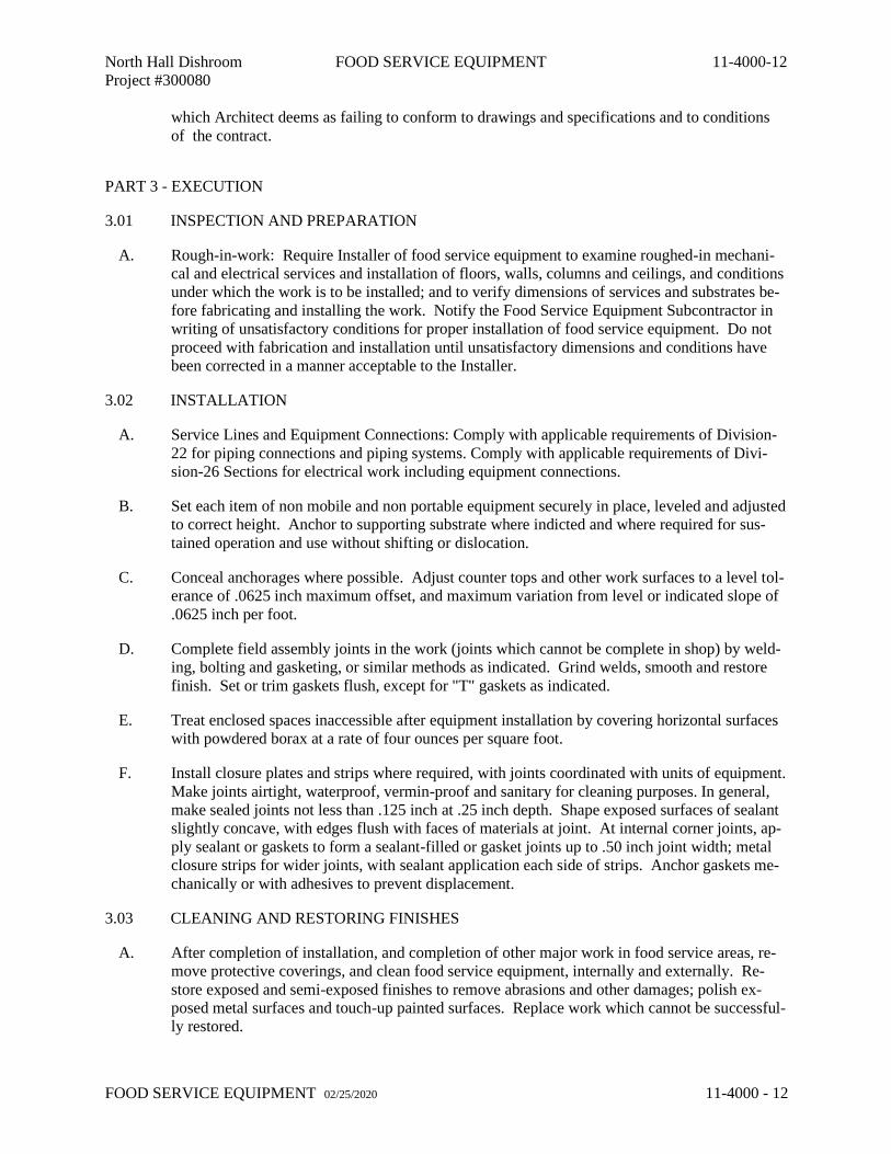
which Architect deems as failing to conform to drawings and specifications and to conditions
of the contract.
PART 3 - EXECUTION
3.01 INSPECTION AND PREPARATION
A. Rough-in-work: Require Installer of food service equipment to examine roughed-in mechani-
cal and electrical services and installation of floors, walls, columns and ceilings, and conditions
under which the work is to be installed; and to verify dimensions of services and substrates be-
fore fabricating and installing the work. Notify the Food Service Equipment Subcontractor in
writing of unsatisfactory conditions for proper installation of food service equipment. Do not
proceed with fabrication and installation until unsatisfactory dimensions and conditions have
been corrected in a manner acceptable to the Installer.
3.02 INSTALLATION
A. Service Lines and Equipment Connections: Comply with applicable requirements of Division-
22 for piping connections and piping systems. Comply with applicable requirements of Divi-
sion-26 Sections for electrical work including equipment connections.
B. Set each item of non mobile and non portable equipment securely in place, leveled and adjusted
to correct height. Anchor to supporting substrate where indicted and where required for sus-
tained operation and use without shifting or dislocation.
C. Conceal anchorages where possible. Adjust counter tops and other work surfaces to a level tol-
erance of .0625 inch maximum offset, and maximum variation from level or indicated slope of
.0625 inch per foot.
D. Complete field assembly joints in the work (joints which cannot be complete in shop) by weld-
ing, bolting and gasketing, or similar methods as indicated. Grind welds, smooth and restore
finish. Set or trim gaskets flush, except for "T" gaskets as indicated.
E. Treat enclosed spaces inaccessible after equipment installation by covering horizontal surfaces
with powdered borax at a rate of four ounces per square foot.
F. Install closure plates and strips where required, with joints coordinated with units of equipment.
Make joints airtight, waterproof, vermin-proof and sanitary for cleaning purposes. In general,
make sealed joints not less than .125 inch at .25 inch depth. Shape exposed surfaces of sealant
slightly concave, with edges flush with faces of materials at joint. At internal corner joints, ap-
ply sealant or gaskets to form a sealant-filled or gasket joints up to .50 inch joint width; metal
closure strips for wider joints, with sealant application each side of strips. Anchor gaskets me-
chanically or with adhesives to prevent displacement.
3.03 CLEANING AND RESTORING FINISHES
A. After completion of installation, and completion of other major work in food service areas, re-
move protective coverings, and clean food service equipment, internally and externally. Re-
store exposed and semi-exposed finishes to remove abrasions and other damages; polish ex-
posed metal surfaces and touch-up painted surfaces. Replace work which cannot be successful-
ly restored.
North Hall Dishroom FOOD SERVICE EQUIPMENT 11-4000-13
Project #300080
FOOD SERVICE EQUIPMENT 02/25/2020 11-4000 - 13
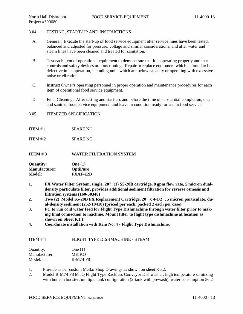
3.04 TESTING, START-UP AND INSTRUCTIONS
A. General: Execute the start-up of food service equipment after service lines have been tested,
balanced and adjusted for pressure, voltage and similar considerations; and after water and
steam lines have been cleaned and treated for sanitation.
B. Test each item of operational equipment to demonstrate that it is operating properly and that
controls and safety devices are functioning. Repair or replace equipment which is found to be
defective in its operation, including units which are below capacity or operating with excessive
noise or vibration.
C. Instruct Owner's operating personnel in proper operation and maintenance procedures for each
item of operational food service equipment.
D. Final Cleaning: After testing and start-up, and before the time of substantial completion, clean
and sanitize food service equipment, and leave in condition ready for use in food service.
3.05 ITEMIZED SPECIFICATION
ITEM # 1 SPARE NO.
ITEM # 2 SPARE NO.
ITEM # 3 WATER FILTRATION SYSTEM
Quantity: One (1)
Manufacturer: OptiPure
Model: FXAF-12B
1. FX Water Filter System, single, 20", (1) S5-20B cartridge, 8 gpm flow rate, 5 micron dual-
density particulate filter, provides additional sediment filtration for reverse osmosis and
filtration systems (160-50340)
2. Two (2) Model S5-20B FX Replacement Cartridge, 20" x 4-1/2", 5 micron particulate, du-
al-density sediment (252-10410) (priced per each, packed 2 each per case)
3. PC to run cold water feed for Flight Type Dishmachine through water filter prior to mak-
ing final connection to machine. Mount filter to flight type dishmachine at location as
shown on Sheet K1.1
4. Coordinate installation with Item No. 4 - Flight Type Dishmachine.
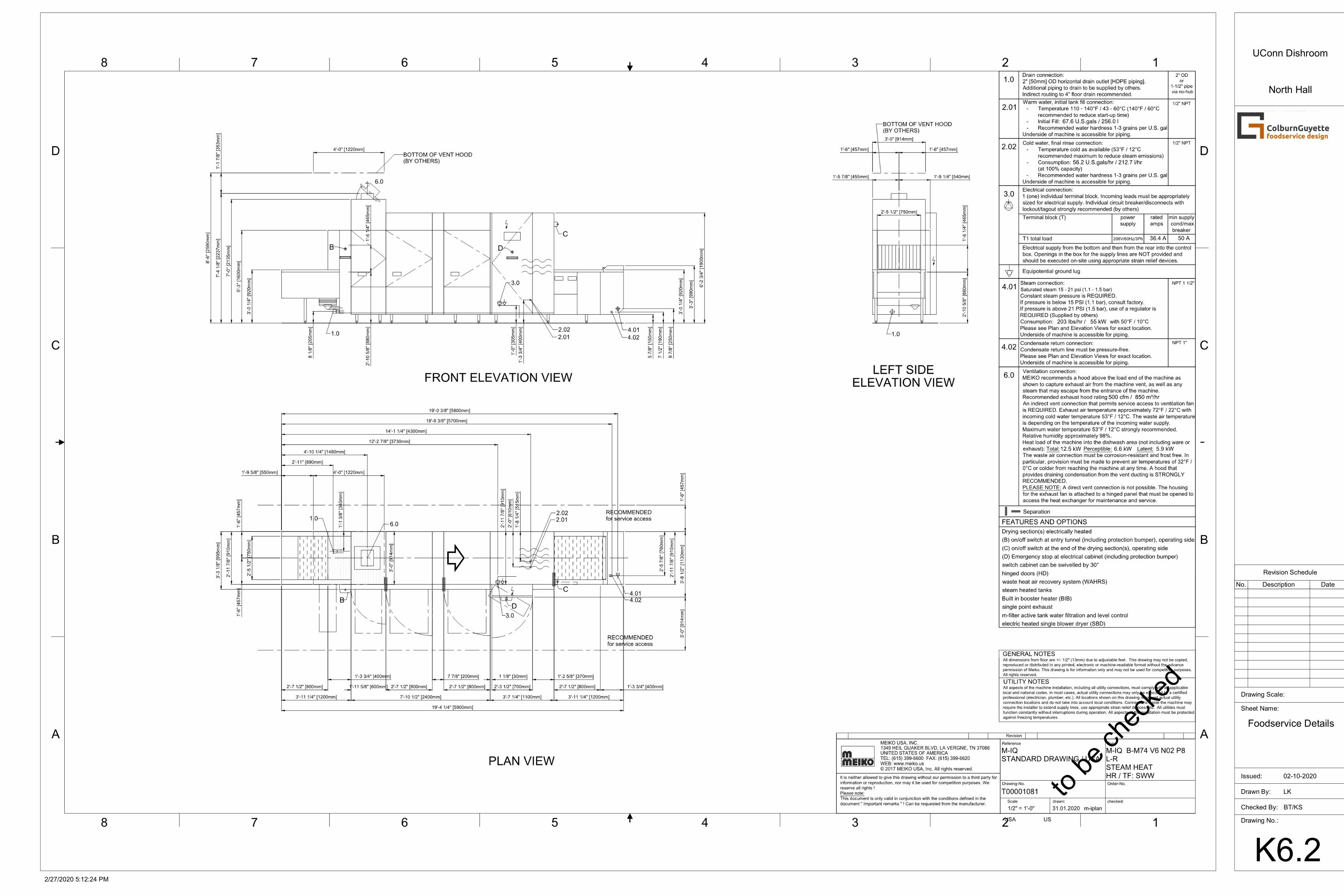
ITEM # 4 FLIGHT TYPE DISHMACHINE - STEAM
Quantity: One (1)
Manufacturer: MEIKO
Model: B-M74 P8
1. Provide as per custom Meiko Shop Drawings as shown on sheet K6.2.
2. Model B-M74 P8 M-iQ Flight Type Rackless Conveyor Dishwasher, high temperature sanitizing
with built-in booster, multiple tank configuration (2-tank with prewash), water consumption 56.2-
North Hall Dishroom FOOD SERVICE EQUIPMENT 11-4000-14
Project #300080
FOOD SERVICE EQUIPMENT 02/25/2020 11-4000 - 14
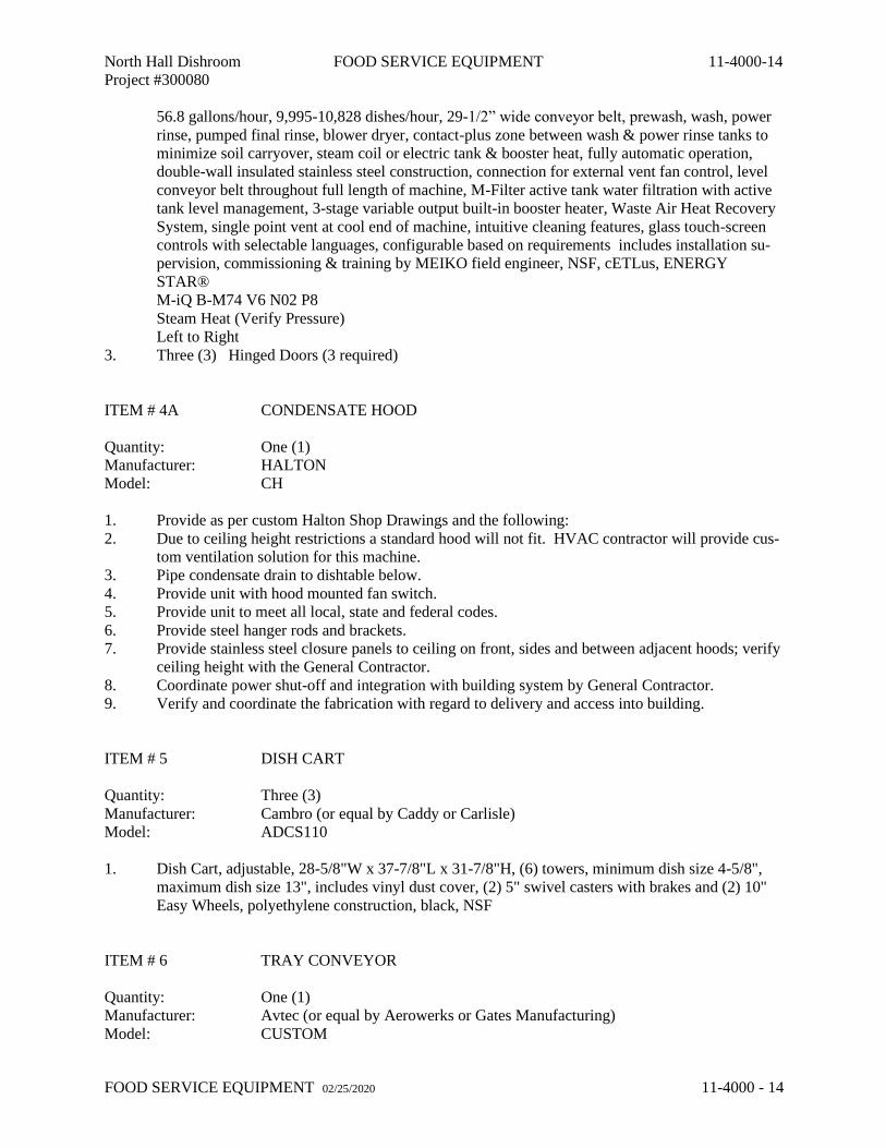
56.8 gallons/hour, 9,995-10,828 dishes/hour, 29-1/2” wide conveyor belt, prewash, wash, power
rinse, pumped final rinse, blower dryer, contact-plus zone between wash & power rinse tanks to
minimize soil carryover, steam coil or electric tank & booster heat, fully automatic operation,
double-wall insulated stainless steel construction, connection for external vent fan control, level
conveyor belt throughout full length of machine, M-Filter active tank water filtration with active
tank level management, 3-stage variable output built-in booster heater, Waste Air Heat Recovery
System, single point vent at cool end of machine, intuitive cleaning features, glass touch-screen
controls with selectable languages, configurable based on requirements includes installation su-
pervision, commissioning & training by MEIKO field engineer, NSF, cETLus, ENERGY
STAR®
M-iQ B-M74 V6 N02 P8
Steam Heat (Verify Pressure)
Left to Right
3. Three (3) Hinged Doors (3 required)
ITEM # 4A CONDENSATE HOOD
Quantity: One (1)
Manufacturer: HALTON
Model: CH
1. Provide as per custom Halton Shop Drawings and the following:
2. Due to ceiling height restrictions a standard hood will not fit. HVAC contractor will provide cus-
tom ventilation solution for this machine.
3. Pipe condensate drain to dishtable below.
4. Provide unit with hood mounted fan switch.
5. Provide unit to meet all local, state and federal codes.
6. Provide steel hanger rods and brackets.
7. Provide stainless steel closure panels to ceiling on front, sides and between adjacent hoods; verify
ceiling height with the General Contractor.
8. Coordinate power shut-off and integration with building system by General Contractor.
9. Verify and coordinate the fabrication with regard to delivery and access into building.
ITEM # 5 DISH CART
Quantity: Three (3)
Manufacturer: Cambro (or equal by Caddy or Carlisle)
Model: ADCS110
1. Dish Cart, adjustable, 28-5/8"W x 37-7/8"L x 31-7/8"H, (6) towers, minimum dish size 4-5/8",
maximum dish size 13", includes vinyl dust cover, (2) 5" swivel casters with brakes and (2) 10"
Easy Wheels, polyethylene construction, black, NSF
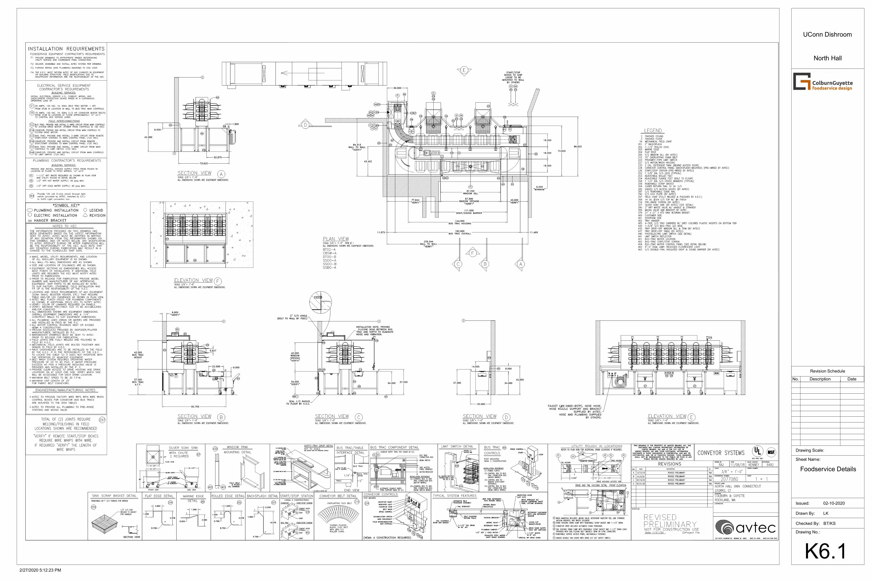
ITEM # 6 TRAY CONVEYOR
Quantity: One (1)
Manufacturer: Avtec (or equal by Aerowerks or Gates Manufacturing)
Model: CUSTOM
North Hall Dishroom FOOD SERVICE EQUIPMENT 11-4000-15
Project #300080
FOOD SERVICE EQUIPMENT 02/25/2020 11-4000 - 15
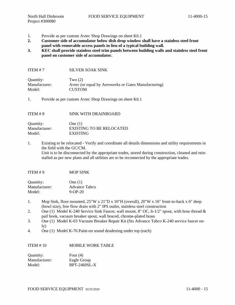
1. Provide as per custom Avtec Shop Drawings on sheet K6.1
2. Customer side of accumulator below dish drop window shall have a stainless steel front
panel with removable access panels in lieu of a typical building wall.
3. KEC shall provide stainless steel trim panels between building walls and stainless steel front
panel on customer side of accumulator.
ITEM # 7 SILVER SOAK SINK
Quantity: Two (2)
Manufacturer: Avtec (or equal by Aerowerks or Gates Manufacturing)
Model: CUSTOM
1. Provide as per custom Avtec Shop Drawings on sheet K6.1
ITEM # 8 SINK WITH DRAINBOARD
Quantity: One (1)
Manufacturer: EXISTING TO BE RELOCATED
Model: EXISTING
1. Existing to be relocated - Verify and coordinate all details dimensions and utility requirements in
the field with the GC/CM.
Unit is to be disconnected by the appropriate trades, stored during construction, cleaned and rein-
stalled as per new plans and all utilities are to be reconnected by the appropriate trades.
ITEM # 9 MOP SINK
Quantity: One (1)
Manufacturer: Advance Tabco
Model: 9-OP-20
1. Mop Sink, floor mounted, 25"W x 21"D x 10"H (overall), 20"W x 16" front-to-back x 6" deep
(bowl size), free flow drain with 2" IPS outlet, stainless steel construction
2. One (1) Model K-240 Service Sink Faucet, wall mount, 8" OC, 6-1/2" spout, with hose thread &
pail hook, vacuum breaker spout, wall braced, chrome-plated brass
3. One (1) Model K-03 Vacuum Breaker Repair Kit (fits Advance Tabco K-240 service faucet on-
ly)
4. One (1) Model K-76 Paint-on sound deadening under top (each)
ITEM # 10 MOBILE WORK TABLE
Quantity: Four (4)
Manufacturer: Eagle Group
Model: BPT-2460SL-X
North Hall Dishroom FOOD SERVICE EQUIPMENT 11-4000-16
Project #300080
FOOD SERVICE EQUIPMENT 02/25/2020 11-4000 - 16
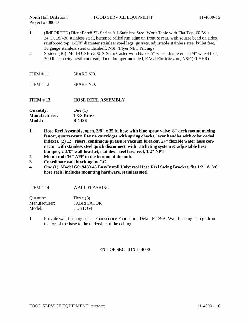
1. (IMPORTED) BlendPort® SL Series All-Stainless Steel Work Table with Flat Top, 60"W x
24"D, 18/430 stainless steel, hemmed rolled rim edge on front & rear, with square bend on sides,
reinforced top, 1-5/8" diameter stainless steel legs, gussets, adjustable stainless steel bullet feet,
18 gauge stainless steel undershelf, NSF (Flyer NET Pricing)
2. Sixteen (16) Model CSB5-300-X Stem Caster with Brake, 5" wheel diameter, 1-1/4" wheel face,
300 lb. capacity, resilient tread, donut bumper included, EAGLEbrite® zinc, NSF (FLYER)
ITEM # 11 SPARE NO.
ITEM # 12 SPARE NO.
ITEM # 13 HOSE REEL ASSEMBLY
Quantity: One (1)
Manufacturer: T&S Brass
Model: B-1436
1. Hose Reel Assembly, open, 3/8" x 35 ft. hose with blue spray valve, 8" deck mount mixing
faucet, quarter-turn Eterna cartridges with spring checks, lever handles with color coded
indexes, (2) 12" risers, continuous pressure vacuum breaker, 24" flexible water hose con-
nector with stainless steel quick disconnect, with ratcheting system & adjustable hose
bumper, 2-3/8" wall bracket, stainless steel hose reel, 1/2" NPT
2. Mount unit 36" AFF to the bottom of the unit.
3. Coordinate wall blocking by GC
4. One (1) Model G019430-45 EasyInstall Universal Hose Reel Swing Bracket, fits 1/2" & 3/8"
hose reels, includes mounting hardware, stainless steel
ITEM # 14 WALL FLASHING
Quantity: Three (3)
Manufacturer: FABRICATOR
Model: CUSTOM
1. Provide wall flashing as per Foodservice Fabrication Detail F2-39A. Wall flashing is to go from
the top of the base to the underside of the ceiling.
END OF SECTION 114000
MP000258147.1.8
SCOPE OF WORK LIMIT LINE
SCOPE OF WORK LIMIT LINE
FD
PB
G
HB
HB
R
FD
FD
SD
X
MD
HS
HSX
ON
/OF
F X
XX
X
X
X
PT
XX
X
X
X
XX
XXPB
XX
ST
RO
BE
T
T
TSTROBE
H
H
67 7
5 5 5
4 4A
DUE TO CEILING HEIGHT RESTRICTIONS A STANDARD HOOD WILL NOT FIT. HVAC CONTRACTOR WILL PROVIDE CUSTOM
VENTILATION SOLUTION FOR THIS MACHINE.
89
10
10
10
10
13
14
14
14
14
3
Checked By:
Drawn By:
Drawing No.:
Sheet Name:
Issued:
Drawing Scale: 1/4" = 1'-0"
2/27/2020 5:12:21 PM
K1.1
LK
BT/KS
Foodservice EquipmentLayout and Utility
Schedule
02-10-2020
UConn Dishroom
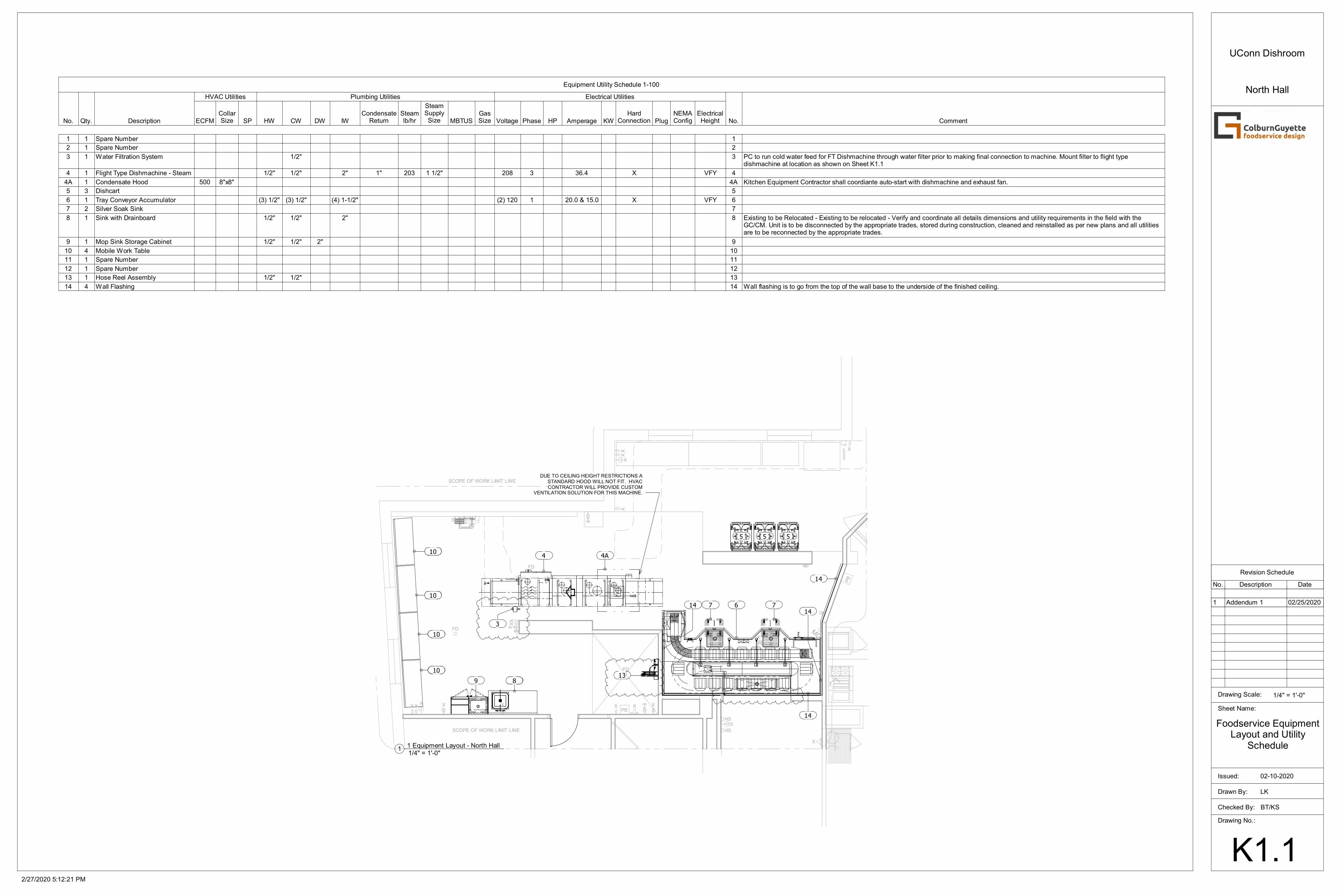
North HallEquipment Utility Schedule 1-100
No. Qty. Description
HVAC Utilities Plumbing Utilities Electrical Utilities
No. CommentECFMCollarSize SP HW CW DW IW
CondensateReturn
Steamlb/hr
SteamSupplySize MBTUS
GasSize Voltage Phase HP Amperage KW
HardConnection Plug
NEMAConfig
ElectricalHeight
1 1 Spare Number 1
2 1 Spare Number 2
3 1 Water Filtration System 1/2" 3 PC to run cold water feed for FT Dishmachine through water filter prior to making final connection to machine. Mount filter to flight typedishmachine at location as shown on Sheet K1.1
4 1 Flight Type Dishmachine - Steam 1/2" 1/2" 2" 1" 203 1 1/2" 208 3 36.4 X VFY 4
4A 1 Condensate Hood 500 8"x8" 4A Kitchen Equipment Contractor shall coordiante auto-start with dishmachine and exhaust fan.
5 3 Dishcart 5
6 1 Tray Conveyor Accumulator (3) 1/2" (3) 1/2" (4) 1-1/2" (2) 120 1 20.0 & 15.0 X VFY 6
7 2 Silver Soak Sink 7
8 1 Sink with Drainboard 1/2" 1/2" 2" 8 Existing to be Relocated - Existing to be relocated - Verify and coordinate all details dimensions and utility requirements in the field with theGC/CM. Unit is to be disconnected by the appropriate trades, stored during construction, cleaned and reinstalled as per new plans and all utilitiesare to be reconnected by the appropriate trades.
9 1 Mop Sink Storage Cabinet 1/2" 1/2" 2" 9
10 4 Mobile Work Table 10
11 1 Spare Number 11
12 1 Spare Number 12
13 1 Hose Reel Assembly 1/2" 1/2" 13
14 4 Wall Flashing 14 Wall flashing is to go from the top of the wall base to the underside of the finished ceiling.
1/4" = 1'-0"1
1 Equipment Layout - North Hall
Revision Schedule
No. Description Date
1 Addendum 1 02/25/2020
MP000258147.1.8
SCOPE OF WORK LIMIT LINE
SCOPE OF WORK LIMIT LINE
FD
PB
G
HB
HB
R
FD
FD
H
H
MP000258147.1.8
SCOPE OF WORK LIMIT LINE
SCOPE OF WORK LIMIT LINE
FD
PB
G
HB
HB
R
FD
FD
SD
X
MD
HS
HSX
ON
/OF
F X
XX
X
X
X
PT
XX
X
X
X
XX
XXPB
XX
ST
RO
BE
T
T
TSTROBE
H
H
4
WALL BLOCKING BY G.C.
DUE TO CEILING HEIGHT RESTRICTIONS A STANDARD HOOD WILL NOT FIT. HVAC CONTRACTOR WILL PROVIDE CUSTOM
VENTILATION SOLUTION FOR THIS MACHINE.
66 6
6
44
4
STEAM SUPPLY
STEAM CONDENSATE RETURN
6
6
8
13
9
PC - RUN COLD WATER FEED FOR FLIGHT TYPE DISHMACHINE THROUGH WATER FILTER PRIOR
TO MAKING FINAL CONNECTION TO MACHINE.
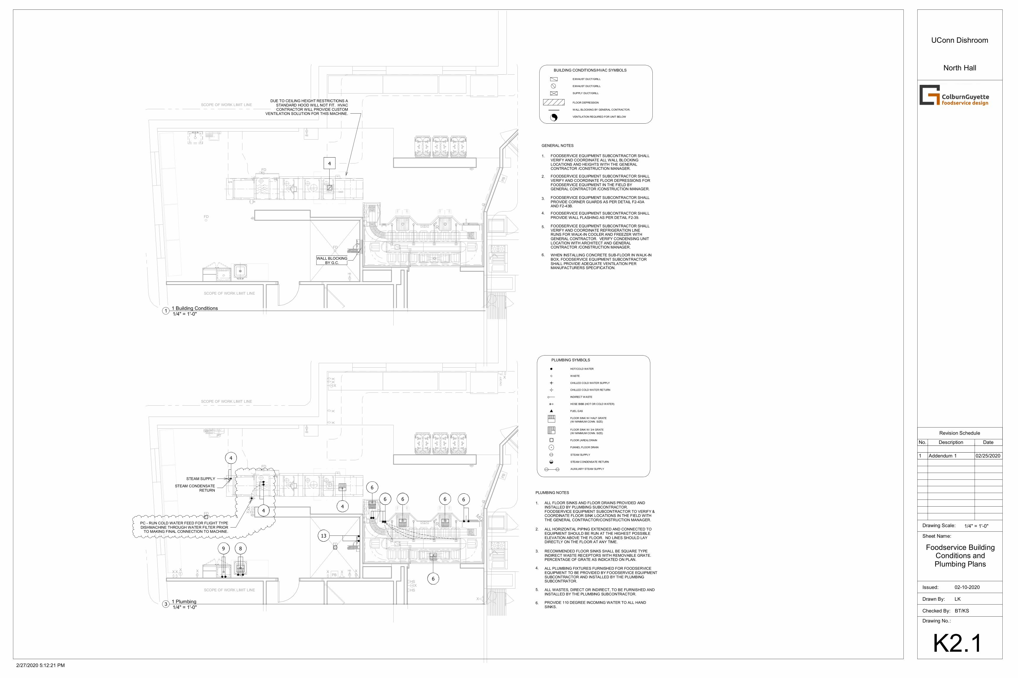
BUILDING CONDITIONS/HVAC SYMBOLS
FLOOR DEPRESSION
WALL BLOCKING BY GENERAL CONTRACTOR.
SUPPLY DUCT/GRILL
EXHAUST DUCT/GRILL
EXHAUST DUCT/GRILL
FOODSERVICE EQUIPMENT SUBCONTRACTOR SHALL PROVIDE WALL FLASHING AS PER DETAIL F2-39.
FOODSERVICE EQUIPMENT SUBCONTRACTOR SHALL VERIFY AND COORDINATE REFRIGERATION LINE RUNS FOR WALK-IN COOLER AND FREEZER WITH GENERAL CONTRACTOR. VERIFY CONDENSING UNIT LOCATION WITH ARCHITECT AND GENERAL CONTRACTOR /CONSTRUCTION MANAGER.
FOODSERVICE EQUIPMENT SUBCONTRACTOR SHALL PROVIDE CORNER GUARDS AS PER DETAIL F2-43A AND F2-43B.
FOODSERVICE EQUIPMENT SUBCONTRACTOR SHALL VERIFY AND COORDINATE FLOOR DEPRESSIONS FOR FOODSERVICE EQUIPMENT IN THE FIELD BY GENERAL CONTRACTOR /CONSTRUCTION MANAGER.
FOODSERVICE EQUIPMENT SUBCONTRACTOR SHALL VERIFY AND COORDINATE ALL WALL BLOCKING LOCATIONS AND HEIGHTS WITH THE GENERAL CONTRACTOR /CONSTRUCTION MANAGER.
5.
4.
3.
2.
GENERAL NOTES
1.
WHEN INSTALLING CONCRETE SUB-FLOOR IN WALK-IN BOX, FOODSERVICE EQUIPMENT SUBCONTRACTOR SHALL PROVIDE ADEQUATE VENTILATION PER MANUFACTURERS SPECIFICATION.
6.
VENTILATION REQUIRED FOR UNIT BELOW
PLUMBING NOTES
PLUMBING SYMBOLS
FLOOR SINK W/ 3/4 GRATE
(W/ MINIMUM CONN. SIZE)
(W/ MINIMUM CONN. SIZE)
FUNNEL FLOOR DRAIN
FLOOR (AREA) DRAIN
CHILLED COLD WATER SUPPLY
CHILLED COLD WATER RETURN
HOSE BIBB (HOT OR COLD WATER)
FLOOR SINK W/ HALF GRATE
FUEL GAS
INDIRECT WASTE
HOT/COLD WATER
WASTE
2.
1.
3.
4.
5.
6.
ALL FLOOR SINKS AND FLOOR DRAINS PROVIDED AND INSTALLED BY PLUMBING SUBCONTRACTOR. FOODSERVICE EQUIPMENT SUBCONTRACTOR TO VERIFY & COORDINATE FLOOR SINK LOCATIONS IN THE FIELD WITH THE GENERAL CONTRACTOR/CONSTRUCTION MANAGER.
ALL HORIZONTAL PIPING EXTENDED AND CONNECTED TO EQUIPMENT SHOULD BE RUN AT THE HIGHEST POSSIBLE ELEVATION ABOVE THE FLOOR. NO LINES SHOULD LAY DIRECTLY ON THE FLOOR AT ANY TIME.
RECOMMENDED FLOOR SINKS SHALL BE SQUARE TYPE INDIRECT WASTE RECEPTORS WITH REMOVABLE GRATE. PERCENTAGE OF GRATE AS INDICATED ON PLAN.
ALL PLUMBING FIXTURES FURNISHED FOR FOODSERVICE EQUIPMENT TO BE PROVIDED BY FOODSERVICE EQUIPMENT SUBCONTRACTOR AND INSTALLED BY THE PLUMBING SUBCONTRATOR.
ALL WASTES, DIRECT OR INDIRECT, TO BE FURNISHED AND INSTALLED BY THE PLUMBING SUBCONTRACTOR.
PROVIDE 110 DEGREE INCOMING WATER TO ALL HAND SINKS.
STEAM CONDENSATE RETURN
AUXILIARY STEAM SUPPLY
STEAM SUPPLY
Checked By:
Drawn By:
Drawing No.:
Sheet Name:
Issued:
Drawing Scale: 1/4" = 1'-0"
2/27/2020 5:12:21 PM
K2.1
LK
BT/KS
Foodservice BuildingConditions andPlumbing Plans
02-10-2020
UConn Dishroom
North Hall
1/4" = 1'-0"1
1 Building Conditions
1/4" = 1'-0"3
1 Plumbing
Revision Schedule
No. Description Date
1 Addendum 1 02/25/2020
MP000258147.1.8
SCOPE OF WORK LIMIT LINE
SCOPE OF WORK LIMIT LINE
FD
PB
G
HB
HB
R
FD
FD
H
H
4
6
6
6
C.P.
J
T
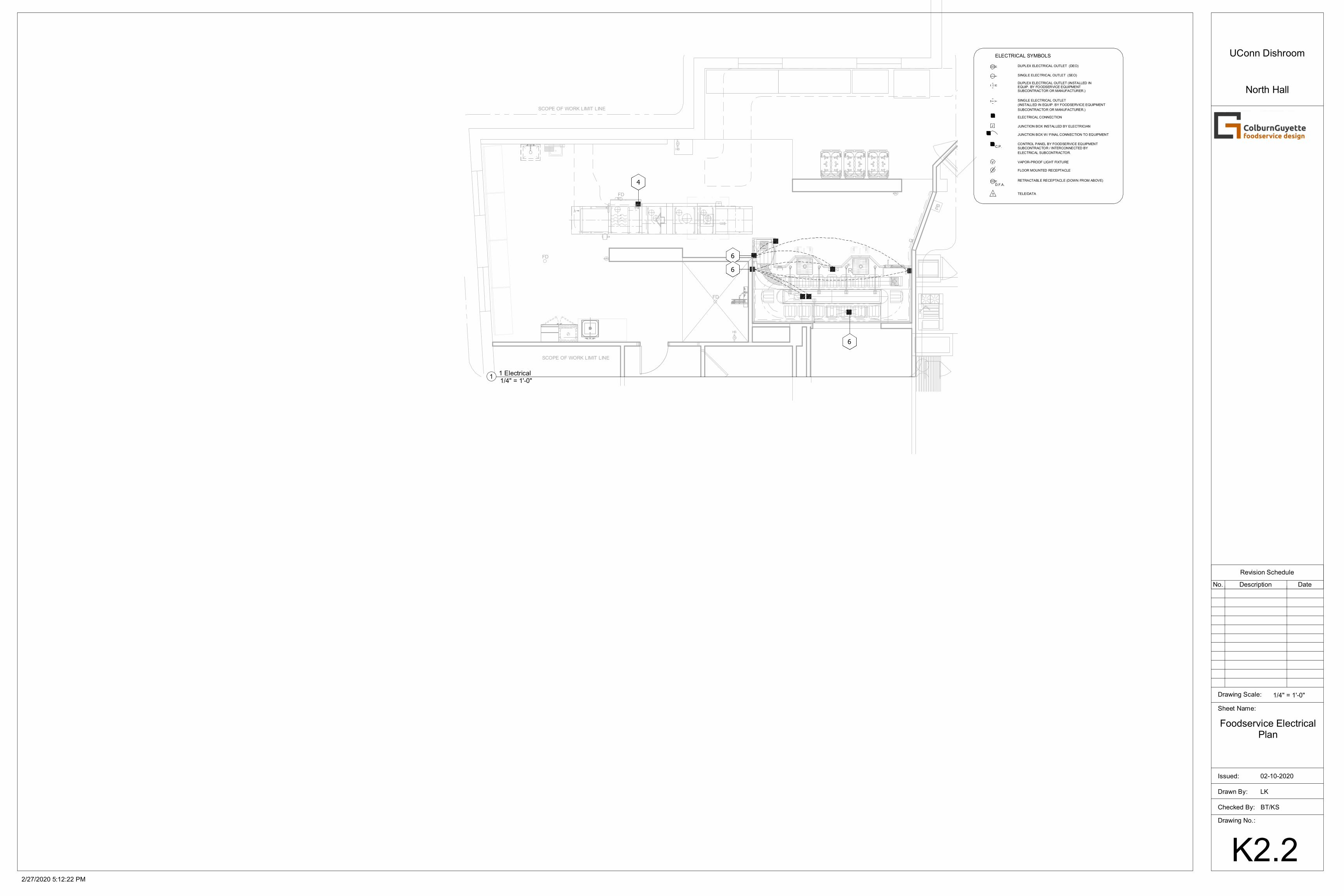
ELECTRICAL SYMBOLS
VAPOR-PROOF LIGHT FIXTURE
FLOOR MOUNTED RECEPTACLE
RETRACTABLE RECEPTACLE (DOWN FROM ABOVE)
JUNCTION BOX W/ FINAL CONNECTION TO EQUIPMENT
CONTROL PANEL BY FOODSERVICE EQUIPMENT
SINGLE ELECTRICAL OUTLET (SEO)
DUPLEX ELECTRICAL OUTLET (DEO)
ELECTRICAL CONNECTION
JUNCTION BOX INSTALLED BY ELECTRICIAN
DUPLEX ELECTRICAL OUTLET (INSTALLED IN EQUIP. BY FOODSERVICE EQUIPMENT SUBCONTRACTOR OR MANUFACTURER.)
SINGLE ELECTRICAL OUTLET
(INSTALLED IN EQUIP. BY FOODSERVICE EQUIPMENT
SUBCONTRACTOR OR MANUFACTURER.)
SUBCONTRACTOR / INTERCONNECTED BY
ELECTRICAL SUBCONTRACTOR.
TELE/DATA
V
D.F.A.
Checked By:
Drawn By:
Drawing No.:
Sheet Name:
Issued:
Drawing Scale: 1/4" = 1'-0"
2/27/2020 5:12:22 PM
K2.2
LK
BT/KS
Foodservice ElectricalPlan
02-10-2020
UConn Dishroom
North Hall
1/4" = 1'-0"1
1 Electrical
Revision Schedule
No. Description Date
Checked By:
Drawn By:
Drawing No.:
Sheet Name:
Issued:
Drawing Scale:
2/27/2020 5:12:23 PM
K6.1
LK
BT/KS
Foodservice Details
02-10-2020
UConn Dishroom
North Hall
Revision Schedule
No. Description Date
Checked By:
Drawn By:
Drawing No.:
Sheet Name:
Issued:
Drawing Scale:
2/27/2020 5:12:24 PM
K6.2
LK
BT/KS
Foodservice Details
02-10-2020
UConn Dishroom
North Hall
Revision Schedule
No. Description Date
Checked By:
Drawn By:
Drawing No.:
Sheet Name:
Issued:
Drawing Scale:
2/27/2020 5:12:24 PM
K6.3
Author
Checker
Foodservice Details
02-10-2020
UConn Dishroom
North Hall
Revision Schedule
No. Description Date


![1005renovation gallery - 住友林業sfc.jp › renovation › img › index › renovation_gallery.pdf · 2019-12-23 · gallery [report #01] ichinoe (tokyo) entrance dining living](https://img.dokumen.tips/doc/110x75/5f0d83ae7e708231d43abcab/1005renovation-gallery-sfcjp-a-renovation-a-img-a-index-a.jpg)