Embed Size (px)
Citation preview

Tiger Cub
REPLACEMENT
Tel. Meriden 331
PARTS CATALOGUE No. 6
for
Models no, TlOC and nos (For T20S see Page 56)
From Engine No. 45312
TRIUMPH ENGINEERING CO. LTD. Meriden Works, Allesley
COVENTRY.
~.f. 4BI,59 Published Marth, J 959

PREFACE
BEFORE ordering parts for your machine, please read very carefully the instructions contained in the next paragraph. In many cases the information given in the order is insufficient to enable us to identify the customers' requirements with
certainty. Delay is frequently occasioned by our having to refer the order back for further particulars before we can supply.
HOW TO ORDER. Every part is indicated by a number and this should be quoted together with the description. In order to assist customers, parts where possible have been listed in order of assembly and exploded illustrations show the assembly order also. By each illustration, is an index quoting the part numbers of the various items and a cross reference to enable the customer to recognise the part by description (See page 69 for further details). With these aids there should be no difficulty in identifying the parts you require. Always quote the engine number and prefix letter stamped on the front engine fixing lug. Always use a separate sheet of writing paper for your order if you are sending a letter as well.
SPECIMEN ORDER
To Triumph Engineering Co. Ltd., Spares Department, Meriden Works, Allesley, Coventry.
Engine No. T.20-46282
Please supply :-
GST20j56
E3146
Gasket Set
Valve, Inlet
* Send C.O.D. Wm. Smith,
2/6/59
Ia, Ewell Avenue, Ewell, Surrey.
* For terms of business see page 3
TELEGRAPHIC ORDERS. Orders by telegram should be addressed to "Trusty 60221 Coventry." They are then telephoned to us, which prevents delay in delivery. It is only necessary to quote part numbers in telegraphic orders, the description can be omitted.
PATTERNS AND PARTS FOR REPAIR. It is not necessary to send patterns if the part number is quoted. The sending of patterns often delays the order as parcel post or rail takes longer than letter post.
2

Parts sent to Coventry for repair, replacement or as patterns, should bear the sender's name and address and clear instructions should accompany the parts. All parts must be forwarded carriage paid and care should be taken to ensure that all remittances are sent separately and not enclosed with the parts. Fragile units such as cylinders, etc., should always be boxed to avoid damage in transit. Complete machines should have all fitments such as horns, driving mirrors, tools, etc., removed by the sender before despatch, as it is impossible for us to accept responsibility in the event of loss in transit. We are always pleased to give estimates for overhauls and repairs, but should an estimate not be accepted, a charge will be made covering cost of dismantling and re-assembling, if carried out.
Communications relating to parts should be addressed to the SPARES MANAGER and for repairs, guarantee claims and technical advice to the SERVICE MANAGER.
"In order to facilitate quick reference, the quoting of any order number, invoice number or reference from previous communications is of essential importance. Accessories not of our manufacture should be sent direct to the actual makers, whose names and addresses appear on page 49.
WHERE TO OBTAIN. Triumph Replacement Parts may be obtained from any Triumph Dealer, and we recommend our customers to place their orders with the Triumph Dealer in their district, as we do not normally supply direct. When parts not usually asked for are required, and for which the Dealer may have to wire or obtain specially, the postage or carriage incurred becomes payable.
We are not able to supply Transfers as originally affixed to Triumph Motor Cycles, but we are at all times willing to supply a Transfer denoting that the machine is of genuine Triumph manufacture, providing the Frame and Engine prefix letters and numbers are quoted.
Customers are warned against the risk incurred by purchasing parts which are not of genuine Triumph manufacture. The risk is eliminated if parts are ordered as instructed, either from our recognised Dealers, or direct from the Spares Department, Meriden Works, Allesley, Coventry.
TERMS OF BUSINESS
THE most convenient method of paying for spare parts is by the C.O.D. system. By this method you pay the postman for the goods when he delivers them to you. As the minimum C.O.D. collection fee is 1/2 only goods to the value of 2/- or over can be sent
by this system. We do not despatch goods by rail C.O.D.
Where goods are not sent C.O.D., cash must accompany the order. All remittances should be made payable to the Triumph Engineering Co., Ltd., and crossed " Barclay's Bank Ltd.", if in the form of Postal Order or Cheque. Letters containing currency notes must be registered.
Should a remittance be forwarded by telegraphic money order, the name and address of the sender must be inserted in the space provided on the Post Office requisition form for a private message from remitter to payee. Unless this is complied with the Post Office omit such information from the telegram and we are not then in a position to trace the sender.
Postage, carriage and packing is charged at 5% on the value of the goods, minimum charge 1/-. Packing boxes, cases, crates, etc., are charged for at cost and are returnable.
3

MODEL T20
MODEL T20C
4

CARTON PACK - GROUP
·CARTON PACK- GROUP I The following sub-assemblies are supplied in carton packs under the C.P. part number
stated. The contents of these carton packs are preserved and will not deteriorate under adverse conditions.
Part No.
Big End Assembly
CP.ISS
Brake linings
CP.I28 2
Piston Assembly
CP.I41
Piston Rings
CP.150
Steering Races
CP.I29
Valves
CP.I24 ...
Valve Guides
CP.I22 ...
Valve Springs
CP.I23 ...
14
I 2
2 2
30
2 2
2 2
Description and Contents
E3624 Connecting rod cfw bushes E3600 Crankpin c'w plug
W978 Linings W979 Rivets
E3358 Piston body E3380 Ring, chrome compression E656 Ring, compression E3387 Ring, scraper E1750 Pin, gudgeon El767 Cirdip, gudgeon pin
E3380 Ring, chrome compression E656 Ring, compression E3387 Ring. scraper
H835 Cup, steering race H833 Cone, steering race S70-3 Ball, steering race
E3146 Valve, inlet E3147 Valve, exhaust
E3208 Valve guide, inlet and exhaust E3209 Cirdip
E3214 ... Spring, valve inner E3215 ... Spring, valve outer
For Indexes see Pages 66 to 68
5

GROUP 2- ENGINE
REPLACEMENT PARTS REF. No. PART No. DESCRIPTION
I 2 3
4 5 6 7 8 9
10 II 12 13 14 IS 16
17 18 19 20 21 22 23 24 25 26 27 28 29 30 31
E3385 E3386 E4037
ENGINE- GROUP 2 Illustrated on Page I 0-Fig. I
CYLINDER BARREL
Barrel, cylinder ... Dowel, cylinder barrel to head ·washer, cylinder base ...
PISTON
CPI41 ;).. Piston c/w rings, gudgeon pin, etc. E656 Ring, compression (top) E3048 Ring, compression (taper) E3387 Ring, oil control El750 ~ Pin, gudgeon El767 i.f- Circlip, gudgeon pin -E4078 E3217 E3207 E3210 E3171 E3230 E3446
E3251 E3252 E3222 E3223 GS662 E3225 E3253 E2534 E2594 E3224 E3227 E3228 E32/.6 E3290 E2441
CYLINDER HEAD
Head, cylinder cjw guides and adaptor Gasket, cylinder head ... Adaptor, cylinder head exhaust Stud, rocker inspection cover ... Stud, cylinder head to carburetter Nut, cylinder head to barrel ... Washer, cylinder head to barrel
OVERHEAD ROCKERS, COVERS
Rocker, inlet assembly ... Rocker, exhaust assembly Ball pin, rocker ... Adjuster, rocker Locknut, rocker adjuster pin Spindle, rocker inlet and exhaust Sealing ring, rocker spindle Thrust washer, rocker spindle L.H.-fir" Thrust washer, rocker spindle R.H.-f' Thackeray washer, washer, rocker spindle (spring) Cover, rocker inlet inspection Cover, rocker exhaust inspection Washer, rocker cover joint Nut, rocker cover to head Washer, rocker cover to head nut
6
QUANTITY
TlO TlOC
I I 2 2
I 2 2
I I I I 2 2 2 2 4 4 4 4
I 2 2 2 2 2 2 2 2 2 2 4 4 2 2 2 2
I
2 2 2 2 2 2

ENGINE- GROUP 2
REF. No. PART No. DESCRIPTION QUANTITY
VALVES, GUIDES & SPRINGS T20TIOC
I E3146 Valve, inlet I 2 E3147 Valve, exhaust ... I I 3 E3208 Guide, inlet and exhaust 2 2 4 E3209 Circlip, inlet and exhaust guide 2 2 5 E3214 Spring, valve inner 2 2 6 E3215 Spring, valve outer 2 2 7 E3301 Collar, valve spring to? 2 2 8 E3213 Cup, valve spring bottom 2 2 9 WE259A Cotter, valve split 4 4
PUSH RODS AND COVER
10 · E3372 Rod, push 2 2 II E3537 Cover, push rod 2 12 E3172 Peg, cover to crankcase locating 13 E3540 Washer, push rod cover joint (upper) 14 E3391 Washer, push rod cover joint (lower)
TAPPETS
IS E3285 Tappet 2 2
ROCKER OIL PIPE
16 E3244 Pipe, rocker oil ... I 17 H400 Nut, rocker oil pipe to spindle 2 2 18 El335 Washer, rocker oil pipe inner joint 2 2 19 E3249 Washer, rocker oil pipe outer joint 2 2 20 E3383 Connection, oil tank to oil pipe (Rubber)
FLYWHEELS AND CONNECTING ROD 21 E3909 Flywheels and connecting rod assembly I I 22 E3910 Flywheels cfw mainshaft L.H. I I 23 E3598 Flywheels cjw plugs R.H. I I 24 E3420 Plug, R.H. Flywheel 2 2 25 E3624 Rod, connecting with bushes I 26 E3623 Bush, big end I 27 El762 Bush, small end ... I 28 E3600 Crankpin cfw plugs I 29 E3292 Plug, crankpin 2 2
7

GROUP 2-ENGINE
REF. No. PART No.
I 2 3 4 5 6 7 8 9
10 II 12 13 14 15
16 17 18 19 20 21
22 23 24 25 2S 27 28 29 30 31
E3930 E3365 E3171 T989 E3169 E3560 TI076 E2615 El335
E3655 E3172 E3175 E3518 E3152 E3379
E4079 E3421 E3185 E3184 E3183 E3186
E3393 E3409 E3410 E3194 E3195 E3412 E3413 570-4 E3191 Tl124
DESCRIPTION
CRANKCASE
Crankcase assembly c;w bushes Stud, crankcase to cylinder head Stud, crankcase to oil pipe junction block Dowel, crankcase to R.H. inner cover Dowel, crankcase to oil junction block Pipe. crankcase oil return Screw, crankcase oil return pipe Plug, crankcase oil gauge test hole Washer, crankcase plug
CRANKCASE BEARINGS (ENGINE)
Bearing, R.H. (Plain) Peg, R.H. bearing Bush, camshaft ... Bush, distributor and oil pump shaft ... Bearing, L.H. (Ball journal) Oil Seal, L.H. Bearing ...
TIMING GEARS AND CAMSHAFT
Pinion, timing and distributor drive Bolt, timing and distributor pinion I U in U.H. Pinion, camshaft (SOT) ... Key, camshaft pinion Camshaft, inlet and exhaust Pinion and shaft, distributor and oil pump drive
OIL PUMP
Oil pump assembly Body, oil pump ... Plunger, oil feed Plunger, oil scavenge Rod, connecting drive Pin, connecting drive rod Circlip, connecting drive rod ... Ball, oil pump body Spring, oil pump body and auxiliary valves Ball, auxiliary valve
8
QUANTITY
nonoc
4 4 I I 2 2
I I 2 2 4 4 2 2

ENGINE - GROUP 2
REF. No. PART No. DESCRIPTION QUANTITY
TlO TlOC E3192 Plug, oil pump body 2 2
2 E3197 Bolt, oil pump to crankcase ~~ in. U.H. 2 2
3 GS299 Lockwasher, oil pump to crankcase (serrated) 2 2
4 E3188 Washer, oil pump to crankcase joint ...
CRANKCASE FILTER 5 E3177 Filter, crankcase ... 6 E3176 Spring, crankcase filter ... 7 E3302 Washer, crankcase filter spring 8 El564 Cap, crankcase filter 9 El577 Washer, crankcase filter joint ...
INNER COVER, LEFT SIDE 10 E3915 Cover, crankcase inner cjw dowels
II El492 Dowel, inner cover to crankcase front 12 T989 Dowel, inner cover to outer cover rear
13 E3932 Sealing washer, gearbox shaft (rubber) 14 E3933 Backing washer, sealing washer IS E3204 Screw, inner cover to crankcase I in. U.H. I I
16 E3445 Screw, inner cover to crankcase Rr in. U.H .... 2 2
17 DS57 Plug, oil level and drain ... 2 2
18 WEI70 Washer, oil level and drain plugs 2 2
ENGINE SPROCKET 19 E3912 Engine sprocket, 19 teeth Duplex 20 E391r Distance piece sprocket and rotor
OUTER COVER, LEFT SIDE 21 E3917 Cover, L.H. outer 22 E3579 Washer, cover joint I 23 E3914 Screw, outer cover, I~ in. U.H. 4 4 24 E3205 Screw, outer cover, q in. U.H. 2 2
25 E3200 Screw, outer cover, -H; in. U.H. 2 2
26 E3204 Screw, outer cover, l in. U.H. I I
27 E2386 Domed nut, middle screws 2 2
28 E2441 Washer, copper 2 2 29 E732 Plug, oil filler 30 NE507 Washer, oil filler plug
9
0
,,
120 I
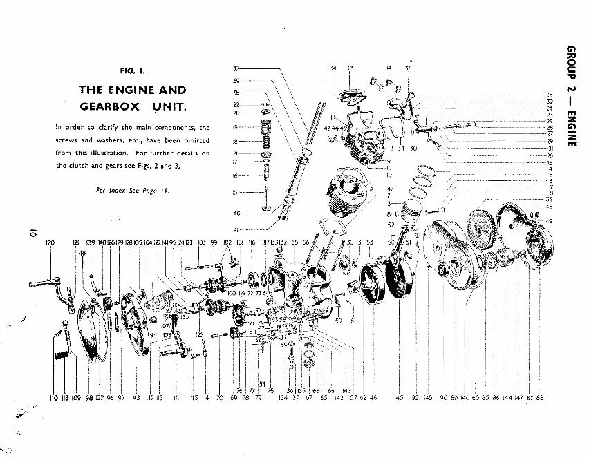
FIG. I.
THE ENGINE AND
GEARBOX I,J NIT.
In order to clarify the main components, the
screws and washers, etc., have been omitted
from this illustration. For further details on
the clutch and gears see Figs. 2 and 3.
For index See Page I I.
l 110 118 109 98 127 96 97 93
36
I
-35 --32
~~~-~~~--~~~~~--~24
- ~~~~~~~--~-23
I I I I
90 89 146 60 85 86 144 87 88
m z C')
z m

INDEX TO FIG. I- PAGE 10
11/ust. No. Part No. Page No. Re(. No. 11/ust. No. Part No. Page No. Ref. No. I E338S 6 I 101 Tlll9 15 29 2 E4037 6 3 52 E1762 7 27 102 T1098 13 II 3 CPI41 6 4 53 E3600 7 28 103 TII02 12 12 4 E656 6 5 54 E2413 8 28 104 TI066 13 13 5 E3048 6 6 55 E3930 8 I 105 TI069 13 14 6 E3387 6 7 56 E3365 8 2 106 Tl248 13 16 7 El750 6 8 57 E3171 8 3 107 TI076 13 18 8 E1767 6 9 58 T989 8 4 108 Tll80 13 19 9 E4078 6 10 59 E3560 8 6 109 Tll64 13 20
10 E3217 6 II 60 E3579 9 22 110 Fl369 13 21 II E3207 6 12 61 TI076 8 7 Ill Tl259 13 22 12 E3210 6 13 62 E3655 8 10 112 Tl184 13 24 13 E3171 6 14 63 E3175 8 12 113 Tl278 13 25 14 .E3230 6 15 64 E3518 8 13 114 TII09 13 27 15 E3146 (in) 7 I 65 E3177 9 5 115 Tl077 13 28
E3147 (ex) 3 2 66 E3176 9 6 116 TI070 14 I 16 E3208 3 3 67 E1564 9 8 117 H 1168 14 2 17 E3209 7 4 68 EIS77 9 9 118 T449 13 30 18 E3214 7 5 69 E4079 8 16 119 TI073 14 4 19 E3215 7 6 70 E3421 8 17 12p Tl230 15 I 20 E3301 7 7 71 E3185 8 IS 121 552-2 15 I 21 E3213 7 8 72 E3184 8 19 122 Tl279 15 9 22 WE259A 7 9 73 E3183 8 20 123 Tl281 15 II 23 E3251 (in) 6 17 74 E3186 8 21 124 Tl282 15 12
E3252 (ex) 6 18 75 E3409 8 23 125 Tll61 15 13 24 E3222 6 19 76 E3194 8 2S 126 Tll62 15 15 25 E3223 6 20 77 E3410 8 26 127 Tll63 15 16 26 G$.662 6 21 78 E3195 8 27 128 Til 57 IS 17 27 E3225 6 22 79 E3412 8 27 129 Til 58 15 18 28 E3253 6 23 80 570-4 8 29 130 Tl513 15 19 29 E2534 6 24 81 E3191 8 30 131 TI082 15 21 30 E2594 6 25 82 E3192 9 I 132 TIIIO 15 22 31 E3224 6 26 83 E3191 8 30 133 E697 IS 23 32 E3228 6 28 84 Tll24 8 31 134 Tlll2 15 24 33 E3227 6 27 85 E3912 9 19 135 Tl257 15 25 m 34 E3226 6 29 86 E3913 9 20 136 T361 15 26 z 35 E3290 6 30 87 E3971 so 9 137 WEI70 15 27 ~ 36 E2441 6 31 88 E3917 9 21 138 Tl493 IS 28 -37 E3372 7 10 _89 E3915 9 10 139 Tl233 16 20 z 38 E3537 7 II 90 E31S2 8 14 140 Tll24 16 24 m 39 E3540 7 13 91 DS-57 9 17 141 Tll40 16 27 40 E3391 7 14 92 WEI70 9 18 142 F879 43 10 41 E3285 7 IS 93 E3476 12 I 143 525-13 43 9 ~ 42 H400 7 17 94 E3293 12 2 144 466124 50 2 :::a 43 E1335 7 18 95 Tll47 12 4 145 El580 50 8 0 44 E3249 7 19 96 Tll49 12 5 146 E3379 8 15 c 45 E3910 7 22 97 Tll48 12 6 147 E4058 50 10
., 46 E3598 7 23 98 E3151 12 13
·~. 14a• E752 9 29 ...,
47 E3386 6 2 99\ See Fig. 2. Page 14 149 NE507 9 30 48 E3345 12 14 IOOJ ISO Tl249 13 17 50 E3624 7 25
GROUP 2 - ENGINE
REF. No. PART No.
2 3 4 5 6 7 8 9
lO II 12
13 14 IS 16 17
E3476 E3293 E31n Tll47 Tll49 Tll48 TIISO E3204 E3220 E3221 F3775 XA69
E3151 E3345 E3221 E3231 E3220
DESCRIPTION
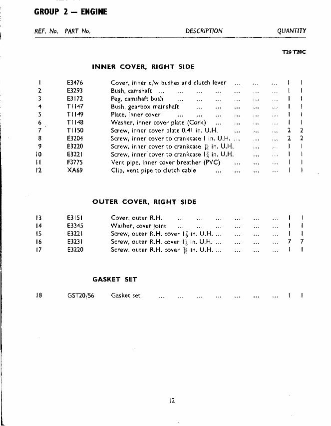
INNER COVER. RIGHT SIDE
Cover, inner cfw bushes and clutch lever Bush, camshaft ... Peg, camshaft bush Bush, gearbox mainshaft Plate, inner cover Washer, inner cover plate (Cork) Screw, inner cover plate 0.41 in. U.H. Screw, inner cover to crankcase I in. U.H. Screw, inner cover to crankcase }-~ in. U.H. Screw, inner cover to crankcase I k in. U.H. Vent pipe, inner cover breather (PVC) Clip, vent pipe to clutch cable
OUTER COVER. RIGHT SIDE
Cover, outer R.H. Washer, cover joint Screw, outer R.H. cover li in. U.H ... . Screw, outer R.H. cover I i in. U.H ... . Screw, outer R.H. cover # in. U.H ... .
GASKET SET
18 GSTI0/56 Gasket set
12
QUANTITY
TlOTlOC
2 2 2 2
I I
I I 7 7
I

GEARBOX- GROUP 3
REF. No. PART No. DESCRIPTION
2 3 4
5
GEARBOX AND CLUTCH- GROUP 3
TIS88* TI085 TIS14 TIS IS TI089
Illustrated on Pages 14 and 17-Figs. 2 and 3
SHAFTS AND GEARS Gear cluster, mainshaft (3rd and low) Bush, mainshaft clutch rod Gear, mainshaft high cjw bush ... Bush. high gear ... Gear, mainshaft 2nd
6 TI090 Thrust ring, mainshaft 2nd gear 7 T I 591 * Gear, cluster, lays haft (top and 2nd) 8 T I 094 Gear, layshaft 3 rd 9 T I 095 Gear, lays haft low cjw bush
I 0 T I 097 Bush, layshaft low gear ...
II 12
13 14 IS 16 17 18 19
20 21 22 23 24 25 26 27 28 29 30
• The gear clusters are sold only as an assembly and the parts cannot be obtai ned separately.
TI098 Tll02
SELECTOR FORKS AND SPINDLE Fork, mainshaft and lays haft selector ... Spindle, selector fork
TI066 TI069 ~"X I" Tl248 Tl249 Tl076 Tll80
Tll64 Fl369 Tl259 Tll81 Tll84 Tl278 IT" X!" Tll09 TI077 E2287 T449
CAM PLATE Camplate assembly Spindle, camplate Split pin, camplate to spindle Spring, camplate index Spring, camplate index (supplementary) Screw, camplate index spring ... Lockwasher, camplate index spring
GEARCHANGE MECHANISM Pedal, gear change Bolt, gear change pedal J in. U.H. Spindle, quadrant and plunger assembly Feltwasher, gear change spindle Plunger, gear change selector Spring, gear change selector plunger Split pin, gear change selector plunger Spring, gear change return Pin, gear change return spring anchorage Washer, gear change return spring anchorage Rubber, gear change pedal
13
QUANTITY
T20 T20C
2 2
2 2
2 2 2 2 2 2 I I
I I
'

GROUP 3 - GEARBOX
REF. No. PART No. DESCRIPTION
I 2 3 4 5 6
3
lllust. No.
I 2 3 4 5 6 7 8 9
TI070 Tll68 TI072 TI073 E3172 Tl269
GEARBOX CASING BEARINGS Bearing, L.H. gearbox mainshaft (ball) Oil seal, L.H. bearing ...
Part No.
Tl588 Tlll9 TI085 Tl514 Tl515 TI089 T1090 Tl591 TI094
Plate, L.H. bearing seal retaining Bearing, L.H. gearbox layshaft (plain) Peg, layshaft bearing locating ... Disc, L.H. gearbox layshaft bearing
6
I !
17 10
7
I
I !~ \:)
II
FIG. 2. MAINSHAFT AND LAYSHAFT GEARS.
INDEX
Page No. Ref. No. lllust. No. Part No.
13 I 10 TI095 15 29 II TI097 13 2 12 Tl279 13 3 13 TillS 13 4 14 Tl281 13 s IS Tl282 13 6 16 Tll61 13 7 17 Tl274 13 8
14
8
Page No.
13 13 15 IS 15 15 15 15
QUANTITY
TlO TlOC
I I 2 2
Ref. No.
9 10 9
10 II 12 13 14
GEARBOX - GROUP 3
REF. No. PART No. DESCRIPTION QUANTITY
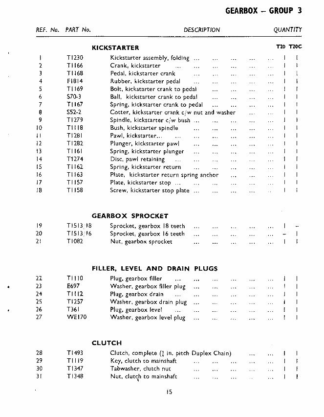
KICKSTARTER T20 noc
Tl230 Kickstarter assembly, folding 2 Tll66 Crank, kickstarter 3 Tll68 Pedal, kickstarter crank 4 Fl814 Rubber, kickstarter pedal 5 Tll69 Bolt, kickstarter crank to pedal 6 S70-3 Ball, kickstarter crank to pedal 7 Tll67 Spring, klckstarter crank to pedal 8 S52-2 Cotter, kickstarter crank cjw nut and washer 9 Tl279 Spindle, kickstarter cjw bush
10 TillS Bush, kickstarter spindle II Tl281 Pawl, kickstarter ... 12 Tl282 Plunger, kickstarter pawl 13 Tll61 Spring, kickstarter plunger 14 T1274 Disc, pawl retaining 15 Tll62 Spring, kickstarter return 16 Tll63 Plate, kickstarter return spring anchor 17 Til 57 Plate, kickstarter stop ... )8 Til 58 Screw, kickstarter stop plate ...
GEARBOX SPROCKET
19 Tl513 1 18 Sprocket, gearbox 18 teeth 20 Tl513jl6 Sprocket, gearbox 16 teeth 21 TI082 Nut, gearbox sprocket
FILLER, LEVEL AND DRAIN PLUGS
22 TIIIO Plug, gearbox filler .. 23 E697 Washer, gearbox filler plug
24 Tlll2 Plug, gearbox drain 25 Tl257 Washer, gearbox drain plug 26 T361 Plug, gearbox level 27 WEI70 Washer, gearbox level plug
CLUTCH
28 Tl493 Clutch, complete(~ in. pitch Duplex Chain) 29 Tlll9 Key, clutch to mainshaft 30 Tl347 Tabwasher, clutch nut 31 Tl348 Nut, clutch to mainshaft
' 15

:;
A :)' :1 i!
GROUP 3 - GEARBOX
REF. No.
I 2 3 4 5 6 7 8 9
10 11 12 13 14 15 16 17 18 19
20 21 22 23 24 25 26 27
PART No
Tl509 Tl124 Tl264 T1345 T1314 T1128 T1364 T1350 T1346 T1132 T1318 T1315 T1503 T1253 T1256 GS662 T1144 T1145 T1146
Tl233 Tl235 Tl236 Tll55 Tll24
fs" X !" Tl234 Tl140
DESCRIPTION
Housing and sprocket (48 teeth) Ball, clutch sprocket bearing ... Bearing ring, clutch sprocket ... Shock absorber assembly comprising lines 6 to 12 ... Clutch centre Backplate ... Cup, centre driving Pin, driving cup ... Spider Rubber," drive Rubber, rebound Driven Plate Driving plate complete with linings Pressure plate Adjuster, pressure plate Nut, for adjuster Cup pressure spring Spring, clutch pressure ... Nut, clutch pin
CLUTCH CONTROL
Lever, clutch operating assembly Lever, clutch operating Pin, operating lever fulcrum Cup, operating lever thrust Ball, cup to rod ... Split-pin, cup to lever ... Fulcrum, clutch operating lever Rod, clutch operating ...
16
QUANTITY
T20 T20C I I
16 16 I I 1 1 1 1 3 3 3 3 1 1 3 3 3 3 3 3 3 3
1 1 1 1 1 3 3 3 3 3 3
I I I
I I I : ...... I I I @ 1
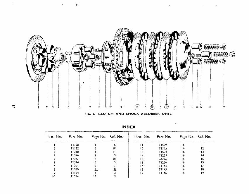
"'-- 2 5 6 7 8 13 13 14 !5 18 19 . FIG. 3. CLUTCH AND SHOCK ABSORBER UNIT.
INDEX
lllust. No. Part No. Page No. Ref. No. lllust. No. Part No. Page No. Ref. No.
I Tll28 16 6 II Tl509 16 I 2 Tll32 16 10 12 Tl315 16 12 3 Tl318 16 II 13 Tl503 16 13 4 Tl346 16 9 14 Tl253 16 14 5 Tl347 IS 30 IS GS662 16 16 6 Tl314 16 5 16 Tl256 16 IS 7 Tl364 16 7 17 Tll44 16 17 8 Tl350 l2- ..a 18 Tll45 16 18 9 Tll24 16 2 19 Tll46 16 19
10 Tl264 16 3
,,
L ' "'"'
GROUP 4 - EXHAUST SYSTEM GROUP 5 - FRAME
REF. No. PART No.
2 3 4 5
6 7 8 9
10 II 12 13 14
IS 16 17 18 19 20 21 22 23 24 25 26 27 28 29
E3257 E3883
,, E3259
E3260 S25-13
E3928 E3840 E3269 TEI64E TEl64D TEI64C F929 S26-l P0172A
F4418 F4420 0402/3 F4051 F4253 F3929 E3843 S25-2 F3953 F3954 S25-2 F3955 F4510 S26-l POI72A
DESCRIPTION
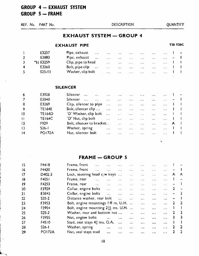
EXHAUST SYSTEM- GROUP 4
EXHAUST PIPE
Pipe, exhaust Pipe, exhaust Clip, pipe to head Bolt, pipe dip Washer, clip bolt
SILENCER
Silencer Silencer Clip, silencer to pipe Bolt, silencer clip ... 'D' Washer, clip bolt 'D' Nut, clip bolt Bolt, silencer to bracket ... Washer, spring Nut, silencer bolt
FRAME- GROUP 5
Frame, front Frame, front Lock, steering head cjw keys Frame, rear Frame, rear Collar, engine bolts Collar, engine bolts Distance washer, rear bolt Bolt, engine mountings t H in. U.H. Bolt, engine mounting 2j~ ins. U.H .... Washer, rear and bottom nut ... Nut, engine bolts Stud, seat stays 4g ins. O.A. Washer, spring Nut, seal stays stud
18
QUANTITY
nonoc
I I
A I
A I
2
2 I 2 3 I 2 2
A
2 I 2 I 2 3 I 2 2

REF. No. PART No. DESCRIPTION
SWINGING FORK I F4068 Swinging fork clw bushes 2 F4076 Bush, fork pivot ... 3 F4079 Spindle, fork pivot 4 F4079 Washer, spacing R.H. 5 F4385 Shim, 0·003 in. ...
6 F4386 Shim, 0·005 in. ... 7 KWI94 Grease nipple, pivot lug 8 WEI70 Washer, fibre
PILLION FOOTREST BRACKETS 9 F4080 Bracket, pillion footrest L.H.
10 F4278 Bracket, pillion footrest L.H. ... II F4081 Bracket, pillion footrest R.H .... 12 F4509 Bolt, bracket to spindle It in. U.H. 13 PCW73A Washer, spring 14 El396 Stud, bracket to frame 11\r in. O.A. IS S26-3 Washer, spring 16 s 1-51 Nut, bracket stud
CRANKCASE SHIELD 17 F4258 Shield, crankcase 18 F4260 Clip, shield 19 DS57 Bolt, clip l6 in. U.H. 20 El612 Washer, shakeproof 21 F879 Nut, clip bolt
STAND- GROUP 6 • CENTRE STAND
22 F3957 Stand, centre 23 F3960 Spring, stand return 24 F3520 Bolt, stand pivot 25 Hl93 Nut, pivot bolt
PROP STAND 26 F3681 Prop stand, cjw fittings 27 F4277 Prop stand, cjw fittings 28 F3097 Pin, stand pivot ... 29 F3096 Tab washer 30 F2610 Spring, stand return
19
FRAME - GROUP 5 STAND - GROUP 6
QUANTITY
T20 T20C
as necessary as necessary
I I
I 2 2 2 2 2 2 2 2 2 2
I 2 2
I 2 2 2
GROUP 5 - FRAME
30 31
I ~···~-J
32----~~-- ----~~~
30-----~~------ ----~
18
18 ---------::>--~, ......
8--------~;;;::-"-=
7 -------------4,
34 -·-------~
12---····-------..._
14----~'9'
13-------~
24 -·----------~'{y 23 ______ __,___,
23 -----:::---:;:2'\
24---
i I
I
I
1!1'}-------------------- 5
-----------4
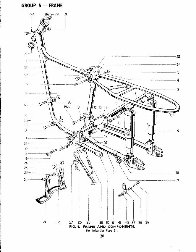
21 22 27 26 25 28 10 6 41 40 37 38 39 FIG. 4. FRAME AND COMPONENTS.
For Index See Page 21.
20
FRAME - GROUP 5
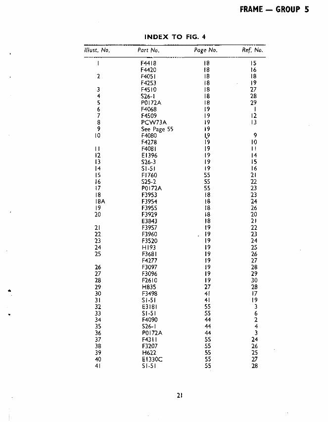
INDEX TO FIG. 4
11/ust. No. Part No. Page No. Ref. No.
F4418 18 IS F4420 18 16
2 F4051 18 18 F4253 18 19
3 F4510 18 27 4 526-1 18 28 5 P0172A 18 29 6 F4068 19 I 7 F4509 19 12 8 PCW73A 19 13 9 See Page 55 19
10 F4080 1.9 9 F4278 19 10
II F4081 19 II 12 E1396 19 14 13 526-3 19 IS 14 Sl-51 19 16 IS Fl760 55 21 16 525-2 55 22 17 P0172A 55 23 18 F3953 18 23 18A F3954 18 24 19 F3955 18 26 20 F3929 18 20
E3843 18 21 21 F3957 19 22 22 F3960 19 23 23 F3520 19 24 24 Hl93 19 25 25 F3681 19 26
F4277 19 27 26 F3097 19 28 27 F3096 19 29 28 F2610 19 30 29 H835 27 28 .. 30 F3498 41 17 31 Sl-51 41 19 32 E3181 55 3 33 Sl-51 55 6 34 F4090 44 2 35 526-1 44 4 36 POI72A 44 3 37 F4311 55 24 38 F3207 55 26 39 H622 55 25 40 EI330C 55 27 41 Sl-51 55 28
21

GROUP 7- TELESCOPIC FRONT FORK
8
7--~---
5-------------- ------- ---------------------
37~-----
28----------
34 --········ ----~---11, /J
23 -------------------+
2 7 ---- ----1----11/----------------<-
26 -------j'----H-1:___~~ ...... -
~~----------33
~w-----------------32
/11------------Jl.~---------- ... ---1
IF---- ---------32
~~~--------~---------]
~~------------4
ff-------~----------16
~----~~--------------24
20~~Ji
Ji~r 12----------------.<J~
'----------------17 /~~---------------~~-----10
~---------------------39
'---------------------------- II
FIG. 5.
TELESCOPIC FRONT FORK.
For Index See Page 23.
22

TELESCOPIC FRONT FORK -GROUP 7
INDEX TO FIG. 5. PAGE 22.
//lust. No. Part No. Page No. Ref. No.
I Hl231 26 3 2 H834 26 5 3 HSIB 26 8 4 S25-3 26 6 5 H837 26 9 6 H570 26 II 7 Sl-51 26 12 8 S25-3 26 13 9 H840 26 14
10 HI035 26 16 II H519A 26 18 12 H845 26 20 13 H846 26 21 14 Hl037 26 22 IS H850 26 24 16 HI047 26 28 17 HI048 26 29 18 Sl-51 26 26 19 HI040 26 30 20 H856 27 5 21 W932 27 7 22 El612 27 6 23 H1043 27 I 24 Hl046 27 8 25 HI045 27 10 26 H862 27 9 27 HI044 27 12 28 H823 27 13 29 H822 27 17 30 H878 27 19
... 31 H877 27 18 32 H833 27 29 33 H836 27 31 34 H873 33 13 35 H864 44 17 36 H865 44 18 37 F879 44 19 38 E2287 26 27 39 H430 26 19 40 WEI70 27 4 41 HI042 27 3
23

GROUP 7 - TELESCOPIC FRONT FORK t3
7
43-----------_r~~
42 ---··-·--------;l ... "<
2
23-·---··---+
25 -··---··--1'~11+----~
27-----~L-11-J'-----·-~
26---+
41-------l 12------~
'-'--- -~ 6 ~-=-----38
17-----···---15
<-------·---] 3
L~ijL----·---··---· -·-32
Uf------,1~--- -~--J
···---···--·-32
-----~--J
,_ ________ -·------·-4
~---------------------17
/11-----------·------------10
FIG. 6. TELESCOPIC FRONT FORK T20C
24

TELESCOPIC FRONT FORK - GROUP 7
INDEX FIG. 6
//lust. No. Part No. Page No. Ref. No.
I Hl233 26 4 2 H834 26 5 3 H518 26 7 4 525-3 26 6 5 H 1133 26 10 6 HS70 26 II 7 Sl-51 26 12 8 525-3 26 13 9 Hll37 26 IS
10 Hll90 26 17 II HSI9A 26 18 12 H845 26 20 13 H846 26 21 14 Hll91 26 23 IS HI 153 26 25 16 HI047 26 28 17 Hf048 26 29 18 51-51 26 26 19 Hll49 26 31 20 H856 27 5 21 W932 27 7 22 El612 27 6 23 HI ISO 27 2 24 HI046 27 8 25 HilS I 27 II 26 H862 27 9 27 HI044 27 12 28 H824 27 14 29 't7 H822 27 17 30 (rt H878 27 19 31 H877 27 18 32 H833 27 29 33 H836 27 31 35 H864 44 17 36 H865 44 18 37 F879 44 19 38 E2287 26 27 39 H430 26 19 40 WE170 27 4 41 HI042 27 3 42 Hl222 27 15 43 0404 27 16
25
GROUP 7 - TELESCOPIC FRONT FORK
REF. No. PART No. DESCRIPTION QUANTITY
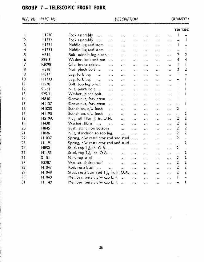
nonoc I Hl230 Fork assembly I 2 Hl232 Fork assembly 3 Hl231 Middle lug and stem 4 H1233 Middle lug and stem 5 H834 Bolt, middle lug pinch 2 2 6 S25-3 Washer, bolt and nut 4 4 7 F3098 Clip, brake cable ... I I 8 H518 Nut, pinch bolt 2 2 9 H837 Lug, fork top
10 Hll33 Lug, fork top II H570 Bolt, top lug pinch 12 Sl-51 Nut, pinch bolt ... 13 S25-3 Washer, pinch bolt 14 H840 Sleeve nut, fork stem IS Hll37 Sleeve nut, fork stem 16 HI035 Stanchion, cfw bush 2 17 Hl190 Stanchion, c/w bush 2 18 H519A Plug, oil filler 1~ in. U.H. 2 2 19 H430 Washer, fibre 2 2 20 H845 Bush, stanchion bottom 2 2 21 H846 Nut, stanchion to top lug 2 2 22 HI037 Spring, c/w restrictor rod and stud 2 23 Hll91 Spring, c/w restrictor rod and stud 2 24 H850 Stud, top I -fk in. O.A. ... 2 25 Hll53 Stud, top 2-{6 ins. O.A .... 2 26 Sl-51 Nut, top stud 2 2 27 E2287 Washer, shakeproof 2 2 28 HI047 Rod, restrictor ... 2 2 29 HI048 Stud, restrictor rod I ;?2 in. in O.A. 2 2 30 HI040 Member, outer, cjw cap L.H. 31 Hll49 Member, outer, cfw cap L.H ....
26

TELESCOPIC FRONT FORK - GROUP 7
REF. No. PART No. DESCRIPTION QUANTITY
T20 T20C I HI043 Member, outer, c/w cap R.H. I 2 HI I 50 Member, outer, cjw cap R.H. I 3 HI042 Stud, oil drain ~~ in. O.A. 2 2 4 WEI70 Washer, fibre 2 2 5 H856 Cap, wheel spindle 2 2 6 El612 Washer, shakeproof 4 4 7 W932 Bolt, spindle cap I in. U.H. 4 4 8 H1046 Bush, fork top ... 2 2 9 H862 Washer, sleeve nut, steel 2 2
10 HI045 Sleeve nut, dust excluder 2 I I HI 151 Sleeve nut, dust excluder 2 12 HI044 Oil seal, rubber ... 2 2 13 H823 Nacelle, bottom unit 14 H824 Nacelle, bottom unit 15 H1222 Gaiter, telescopic 2 16 D404 Clip, gaiter 2 17 H822 Nacelle, top unit.f 18 { H877 ( Flash, L.H. (motif) 19 H878 Flash R.H. (motif) I 20 H688 Screw, flash and top and bottom unit fir in. U.H. 2 2 21 H691 Nut, flash and top and bottom unit ... 2 2 22 E2880 Washer. flash and top and bottom unit 2 2 23 H916 Screw, flash and top and bottom unit (centre) i1z in. U.H. 2 2 24 H689 Screw, top and bottom unit (rear) l in. U.H. 2 2 25 H691 Nut, top and bottom unit (rear) 2 2 26 E2880 Washer, top and bottom unit (rear) 2 2 27 H961 Grommet, control cables 3 3
• STEERING RACES
28 H835 Cup, steering race (top and bottom) 2 2 29 H833 Cone, steering race (top and bottom) 2 2 30 S70-3 Ball, steering race (top and bottom) 30 30 31 H836 Cover, steering race, dust I I
27

~ :liD
10 3 5 II 0 c,
I .,I Cl:) I
LONG 19 I I
~:
" 18 :c·
m m r-VI
17
13
21
f-.) (X)
SHORT
I 9 8 6 2 4 12 14 20
FIG. 7. FRONT WHEEL.
For Index See Page 29.

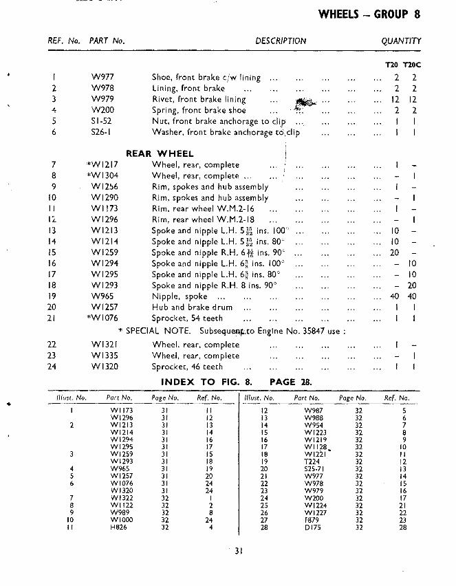
WHEELS - GROUP 8
REF. No. PART No. DESCRIPTION
WHEELS- GROUP 8
FRONT WHEEL I Wll71 Wheel, front complete
~2 W13Q3 Wheel, front complete ... 3 Wl172 Rim, spokes and hub assembly 4 Wl285 Rim, spokes and hub assembly 5 W1173 Rim, front wheel, W.M.2.-16 ... 6 WI002 Rim, front wheel, W.M.I-19 ... 7 Wll74 Spoke and nipple, L.H. 6~ ins. 90° 8 Wll75 Spoke and nipple, R.H., 5-H ins. 90o 9 Wl289 Spoke and nipple L.H., Bt in. 90°
10 Wl205 Spoke and nipple, R.H. 6i ins. 100° II Wl206 Spoke and nipple, R.H. 6* ins. soo 12 W965 Nipple, spoke 13 W961 Hub and brake drum 14 Wl286 Hub and brake drum IS W967 Spindle, front wheel 16 WI093 Nut, front wheel spindle to anchor plate 17 T530 Bearing, front wheel L.H. 18 W966 Dust cap, front wheel L.H. 19 T532 Circlip, front wheel L.H. dust cap 20 H826 Bearing, front wheel R.H. 21 W968 Ring, front wheel R.H. locking
FRONT WHEEL BRAKE 22 W1065 Plate, front brake anchor 23 Wl128 Cam assembly, front brake 24 Wll33 Lever, front brake 25 T224 Nut, front brake lever ... 26 S25-71 Washer, front brake lever
INDEX TO FIG. 7. PAGE 28.
1//ust. No. Part No. Page No. Ref. No. //lust. No. Part No. Wll73 29 5 9 W966 WI002 29 6 10 T532
2 Wll75 29 8 II H826 Wl205 29 10 12 W968 Wl206 29 II 13 Wl065
3 Wll74 29 7 14 Wll28 Wl289 29 9 IS Wll33
4 W965 29 12 16 T224 5 W961 29 13 17 W977
Wl286 29 14 18 W978 6 W967 29 IS 19 W979 7 WI093 29 16 20 W200 8 TS30 29 17 21 Sl-52
29
Page No. 29 29 29 29 29 29 29 29 31 31 31 31 31
QUANTITY
nonoc
- .. I
20 20
- 20 - 10 - 10
40 40 I
Ref. No. 18 19 20 21 22 29 24 25
I 2 3 4 5

bKUUt" H- VYHttU !@r--------------~
~~---: Q
1.0-·~-------------~ st-----'~
~~-------------r:·t::::l-,
~--------------~
N-------------~
v N
N
30
t"r-',
_,------------v
~------------~ ~
!1------~--(\J <I)
()\
~tfJ( ....... N
..0
~ N
lt'l N
~ 0
WHEELS- GROUP 8
REF. No. PART No. DESCRIPTION
I 2 3 4 5 6
7 8 9
10 II I'L. I 3 14 IS 16 17 18 19 20 21
22 23 24
1/fust. No.
2
3
4 5 6
7 8 9
10 II
W977 W978 W979 W200 Sl-52 S26-l
*WI217 *WI304 Wl2~6
Wl290 Wll73 Wl296 Wl213 Wl214 Wl259 Wl294 Wl295 Wl293 W965 Wl257
Shoe, front brake cjw lining Lining, front brake Rivet, front brake lining Spring, front brake shoe Nut, front brake anchorage to clip ... Washer, front brake anchorage t~\clip
REAR WHEEL Wheel, rear, complete Wheel, rear, complete ... Rim, spokes and hub assembly Rim, spokes and hub assembly Rim, rear wheel W.M.2-16 Rim, rear wheel W.M.2-18 Spoke and nipple L.H. Si& ins. 100" Spoke and nipple L.H. sg ins. 80° Spoke and nipple R.H. 6-n ins. 90 9
Spoke and nipple L.H. 6~ ins. I ooc Spoke and nipple L.H. 6~ ins. 80° Spoke and nipple R.H. 8 ins. 90° Nipple, spoke ... Hub and brake drum
*WI076 Sprocket, 54 teeth
* SPECIAL NOTE. Subseque.n~,to Engine No. 35847 use :
Wl321 Wheel, rear, complete Wl335 Wheel, rear, complete W 1320 Sprocket, 46 teeth
INDEX TO FIG. 8. PAGE 28.
Part No. No. //lust. No. Part No.
Wll73 31 II 12 W987 Wl296 31 12 13 W988 Wl213 31 13 14 W954 W1214 31 14 15 Wl223 W1294 31 16 16 W1219 Wl295 31 17 17 Wll78. Wl259 31 15 18 Wl221 Wl293 31 18 19 T224 W965 31 19 20 S25-71 Wl257 31 20 21 W977 WI076 31 24 22 W978 Wl320 31 24 23 W979 Wl322 32 I 24 W200 Wll22 32 2 25 Wl224 W989 32 8 26 Wl227 WIOOO 32 24 27 F879 H826 32 4 28 0175
31
32 32 32 32 32 32 32 32 32 32 32 32 32 32 32 32 32
QUANTITY
no noc 2 2 2 2
12 12 2 2
10 10 20
I
- 10 10
- 20 40 40
I I
No.
5 6 7 8 9
10 II 12 13 14 15 16 17 21 22 23 28

GROUP 8 - WHEELS
REF. No. PART No. DESCRIPTION QUANTITY
no noc Wl322 Bolt, sprocket to drum, ~ in. U.H. 8 8
2 Wl122 Washer, spring 8 8 3 W989 Spindle, rear wheel I I 4 H826 Bearing, rear wheel, L.H. and R.H. 2 2 5 W987 Backing ring, L.H. bearing I I 6 W988 Locking ring, L.H. bearing I 7 W954 Distance piece, R.H. inner I 8 Wl223 Distance piece, R.H. outer I
REAR WHEEL BRAKE
9 Wl219 Plate, brake anchor I 10 Wl128 Carr. brake I II Wl221 Lever, rear brake ... I I 12 TI24 Nut, brake lever I I 13 S25-71 Washer, plain I I 14 W977 Shoe, brake c/w lining ... 2 2 15 W978 Lining, brake 2 2 16 W979 Rivet, brake lining 12 12 17 W200 Spring, shoe return 2 2 18 H211 Bolt, brake anchor, flt in. U.H. I I 19 F2184 Washer, plain I I 20 F3955 Nut, anchor bolt I I
REAR CHAIN ADJUSTER
21 Wl224 Adjuster, rear chain 2 2 22 Wl227 End plate, adjuster 2 2 23 F879 Nut, adjuster 2 2 24 WIOOO Nut, wheel spindle 2 2
32

MUDGUARDS - GROUP 9
REF. No. PART No. DESCRIPTION QUANTITY
MUDGUARDS -GROUP 9
FRONT MUDGUARD T2tl T20C
I H929 Mudguard, front I> 2 HI I 56 Mudguard, front 3 H871 Stay, mudguard, LH. 4 H872 Stay, mudguard, R.H. 5 HI I 57 Stay assembly 6 Hl161 Bridge, mudguard support I 7 DS57 Bolt, mudguard stay, * in. U.H. 4 6 8 E1612 Washer, shakeproof 4 9 S25-l Washer, plain 6
10 F879 Nut, mudguard ... 4 6 II F879 Nut, stay to fork lug 2 2 12 El612 Washer, shakeproof 2 2 13 H873 Clip, bridge to fork leg 2 14 GS218 Bolt, clip and bridge irys in. U.H. 2 4
IS El612 Washer, shakeproof 2 4 16 F879 Nut 2 4
LICENCE HOLDER
17 D261 Licence holder ...
REAR MUDGUARD
18 F4497 Mudguard, rear ... 19 F4270 Mudguard, rear ... 20 F4499 Mudshield, inner 21 F4502 Stay, mudshield front 2 22 F4262 Stay, mudguard front 2 23 DS57 Bolt, guard to stay and frame * in. U.H. 4 4 24 S25-1 Washer, plain 4 4 25 F879 Nut, mudguard bolts ... 4 4 26 F4531 Bolt, stays and oil tank to frame ll in. U.H. 27 DSSS Bolt, stays to frame in. U.H. 28 S26-3 Washer, spring 29 Sl-51 Nut, stay bolt
33

GROUP 9- MUDGUARDS
,..--------7
----6
'-----4 ----------3
~~~~~----------2
,-----29
10
9
r 14
~
rr 16
12 II
31
FIG. 9. MUDGUARDS, NUMBER PLATES AND REAR CHAINGUARO. See Page 36 for Rear Panels.
J4
t
t
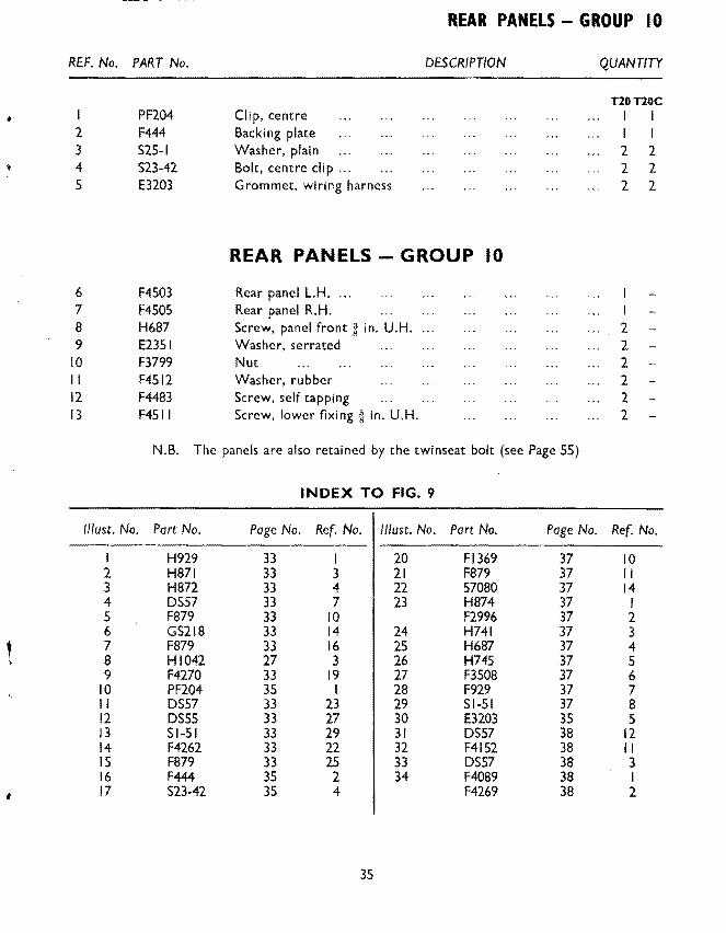
REF. No. PART No.
2 3 4 5
6 7 8 9
10 II 12 13
PF204 F444 S25-l S23-42 E3203
F4503 F4505 H687 E2351 F3799 F4512 F4483 F4511
Clip, centre Backing plate Washer, plain Bolt, centre clip ... Grommet, wiring harness
REAR PANELS - GROUP I 0
DESCRIPTION QUANTITY
T20T20C I I I I 2 2 2 2 2 2
REAR PANELS- GROUP 10
Rear panel L.H. . .. Rear panel R.H. Screw, panel front·~· in. U.H. 2 Washer, serrated 2 Nut 2 Washer, rubber 2 Screw, self tapping 2 Screw, lower fixing ·~ in. U.H. 2
N.B. The panels are also retained by the twinseat bolt (see Page 55)
INDEX TO FIG. 9
1/lust. No. Part No. Page No. Ref. No. 11/ust. No. Part No. Page No. Ref. No.
I H929 33 I 20 Fl369 37 10 2 H871 33 3 21 F879 37 II 3 H872 33 4 22 57080 37 14 4 DS57 33 7 23 H874 37 I 5 F879 33 10 F2996 37 2 6 GS218 33 14 24 H741 37 3 7 F879 33 16 25 H687 37 4 8 HI042 27 3 26 H745 37 5 9 F4270 33 19 27 F3508 37 6
10 PF204 35 I 28 F929 37 7 II OS 57 33 23 29 s 1-51 37 8 12 DSSS 33 27 30 E3203 35 5 13 Sl-51 33 29 31 OS 57 38 12 14 F4262 33 22 32 F4152 38 II IS F879 33 25 33 OS 57 38 3 16 F444 35 2 34 F4089 38 I 17 S23-42 35 4 F4269 38 2
35

GROUP 10- REAR PANELS
7----{-1;\
6----"
5 --------'
15 14
16 17 18 13 9 23 19 22
FIG. 10. REAR PANELS.
36

---- - ----
NUMBER PLATES - GROUP II
REF. No. PART No. DESCRIPTION QUANTITY
NUMBER PLATES-GROUP II
t FRONT NUMBER PLATE T20T20C
' H874 Plate, front number 2 F2996 Plate, front number 3 H741 Clip, assembly, front number plate 2 2 4 H687 Screw, front number plate to clip 2 2 5 H745 Nut, clip screw ... 2 2
REAR NUMBER PLATE
6 F3S08 Plate, rear number 7 F929 Bolt, number plate top~ in. U.H. 8 SI-S I Nut, top bolt 9 526-3 Washer, top bolt
10 Fl369 Bolt, number plate bottom~· in. U.H. 2 2 II F879 Nut, bottom bolt 2 2 12 526-2 Washer, bottom bolt ... 2 2 13 D68 Transfer, number plate motif ... 14 S7080 Reflector, c!w nut and washer
INDEX TO FIG. 10.
//lust. No. Part No. Page No. Ref. No. //lust. No. Part No. Page No. Ref. No.
I F4SOS 3S 7 13 F4499 33 20 2 F4S03 3S 6 14 F4S02 33 21 3 F4483 3S 12 IS F4531 33 26 4 F4512 35 II 16 Sl-51 33 29 5 H687 35 8 17 DSS7 33 23 6 E2351 3S 9 18 F379 33 25 7 F3799 35 10 19 F3508 37 6 8 F4SII 35 13 20 F929 37 7 9 F4497 33 18 21 SI-S I 37 8
10 PF204 35 I 22 Fl369 37 10 II 523-42 3S 4 23 F879 37 II 12 F444 3S 2
37

GROUP 12- REAR CHAINGUARD GROUP 13- TOOLBOX, BATTERY CARRIER AND AIR CLEANER
REF. No. PART No. DESCRIPTION QUANTITY
I 2 3 4 5 6 7 8 9
10 II 12 13 14
IS 16 17 18 19 20 21 22 23 24 25 26 27 28 29 30 31 32
F4089 F4269 DSS7 S26-2 S25-l F4265 E2818 F4263 El612 F879 F4152 OS 57 525-13 S26-2
REAR CHAINGUARD- GROUP
Chainguard, rear ... Chainguard, rear ... Bolt, front and rear Washer, spring (front) Washer, plain (rear) Clip, to swinging fork Bolt, clip I in. U.H. Distance piece ... Washer, shakeproof Nut, eli p bolt Chainguard, front portion Bolt, to crankcase -{6 in. U.H .... Washer, plain Washer, spring
12 T20T20C
2 2 I I
TOOLBOX, BATTERY CARRIER AND AIR CLEANER GROUP 13
F4515 Battery casejtoolbox F3491 Battery case/toolbox F3470 Rubber pad, for battery F3418 Container, air cleaner H251 Beading, air cleaner F3492 Element, air cleaner F3656 Stud, air cleaner to case H745 Nut, air cleaner to case F3473 Strap, battery case F3472 Hook-bolt, battery case strap and lid F879 Nut, battery case hook bolt F3493 Lid, casing cfw knob F3474 Knob, casing lid F3475 Circlip, casing lid knob ... F4469 Connector, air cleaner to carburetter 199002 Grommet, wiring harness 525-2 Washer, plain 51-52 Nut, top fixing ...
Rear fixing at coil bracket Page SO, and lower fixing at mudguard bracket Page 33
38
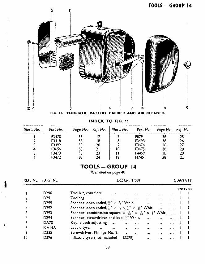
TOOLS - GROUP 14 2
12 4 3 6 5 7 10 8 9 FIG. II. TOOLBOX, BATTERY CARRIER AND AIR CLEANER.
INDEX TO FIG. 11
1/fust. No. Part No. Page No. Ref. No. lllust. No. Part No. Page No. Ref. No.
I F3470 38 17 7 F879 38 25 2 F3418 38 18 8 F3493 38 26 3 F3492 38 20 9 F3474 38 27 4 F3656 38 21 10 F3475 38 28 5 F3473 38 23 II F4469 38 29 6 F3472 38 24 12 H745 38 22
TOOLS- GROUP 14 Illustrated on page 40
1 REF. No. PART No. DESCRIPTION QUANTITY
nonoc 0290 Tool kit, complete I I
2 0291 Tool bag ... 3 0299 Spanner, open ended,~" x Whit. 4 0292 Spanner, open ended, §" x jk x ! " x is" Whit. 5 0293 Spanner, combination square X 136
11 X is* X i* Whit.
6 0294 Spanner, screwdriver and box, t" Whit. 7 OA70 Key, clutch adjusting ... ... 8 NAI4A Lever, tyre 9 0335 Screwdriver, Phillips No.2
10 0296 Inflator, tyre (not included in 0290)
39

GROUP 14- TOOLS
D296
e;-····· -D294---·UJD
FIG. 12. TOOLS.
40

PETROL AND OIL TANKS- GROUP IS
REF. No. PART No. DESCRIPTION QUANTITY
I 2 3 4 5 6 7 8 9
10 II 12 13 14 IS 16 17 18 19
20 21 22 23 24 25 26
//lust. No.
2 3 4 s 6 7 8 9
10 II 12
PETROL AND OIL TANKS- GROUP 15 PETROL TANK TlOTlOC
F4496 F3505 F3220 F4048 F4570 F4571 F4468 F3494 F3495 F3496 F3497 F3506 E697 F4537 Fl605 Fl606 F3498 S25-3 s 1-51
Petrol tank, less fittings Petrol tank, less fittings Cap. filler cjw washer Washer, filler cap Styling unit, L.H. Styling unit, R.H. Screw, styling unit [6 in. U.H. Styling band L.H. Styling band R.H. Name plate Screw, name plate it in. U.H. Tap, petrol Washer, fibre Pipe, petrol feed Knee grip, R.H .. .. Knee grip, L.H ... . Bolt, tank to frame 2~ in. U.H. Washer, plain Nut, tank bolt ...
OIL TANK F4490 F4318 F3216 F4047 Fl792 PT104B A3
Part No.
F4496 F3505 F3220 F4570 F4571 F4468 Tl203 F3506 E697 F4537 Fl605 Fl606 F4490 F4318
Oil tank, less fittings Oil tank, less fittings Cap, filler c/'!" washer Washer, filler cap Drain plug, oil tank Washer, fibre Transfer (Minimum Oil level)
INDEX TO FIG. 13. PAGE 42.
Page No. Ref. No.
41 I 41 2 41 3 41 s 41 6 41 7 43 19 41 12 41 13 41 14 41 IS 41 16 41 20 41 21
41
//lust. No.
13 14 IS 16 17 18 19
20 21 22 23
Part No.
F3216 F3876 FISII E3270 F3S03 F3504 F4530 F3077 E3244 E3383 F1792 PTI04B
I I I I 4
2 I
I I I I I I 2 2 3 3 2 2
Page No. Ref. No.
41 22 43 I 43 2 43 6 43 6 43 7 43 3 43 4
7 16 7 20 7 24 7 2S

\IKUUl"'"l!f..;.;-rtiKUL ANU UIL lANK.)
4---
3--------------
19 17 16
@ 8
~7 -
~--------------20
~----------------------13
10 FIG. 13. PETROL AND OIL TANKS.
For Index See Page 41.
42

PETROL AND OIL TANKS - GROUP IS
FOOTRESTS- GROUP 16
REF. No. PART No. DESCRIPTION QUANTITY
T20T20C
I F3876 Fi Iter, oil tank ... I -, 2 Fl511 Washer, fibre I
3 F4530 Connection, rubber 2 4 F3077 Connection. rubber 2 5 E3270 Pipe assembly, tank to engine ... 6 F3503 Feed pipe. top half 7 F3504 u nl0i1nut"Teedpi pe 8 F3274 Joint washer, pipe to engine 9 525-13 Washer, plain
10 F879 Nut, pipe to engine II 525-2 Washer, plain 12 Sl-52 Nut, oil tank to frame stud 13 F2596 Bolt, tank to frame bottom I~ in. U.H. I 14 F3477 Distance piece, bottom I 15 F3468 Bolt, tank to frame top 2l6 in. U.H. I 16 F3476 Distance piece, top 2 17 s 1-51 Nut, tank bolts ... 2 18 S-25-3 Washer, top bolt I 19 Tl203 Vent pipe, oil tank (flexible)
FOOTRESTS- GROUP 16 20 F4383 Footrest LH. I 21 F3450 Footrest R.H. I I 22 F1695 Rubber 2 2 23 F3448 Rod, footrest hanger 6! in. O.A. I I 24 Hl93 Nut, footrest rod 2 2
PILLION FOOTREST
25 F4327 Footrest, pillion complete 2 2 26 Fl694 Pedal, footrest ... 2 2
' Fl695 Rubber, footrest pedal 2 2 F2271 Bolt, footrest pedal pivot 2 2 Sl-51 Nut, footrest pedal pivot bolt 2 2 F2277 Washer, footrest pedal pivot bolt 2 2
31 F2268 Hangar, footrest pedal ... 2 2 32 F4309 Stud, footrest pedal I~ in. O.A. 2 2 33 POI72A Nut, footrest pedal stud 2 2 34 526-1 Washer, footrest pedal stud 2 2
43
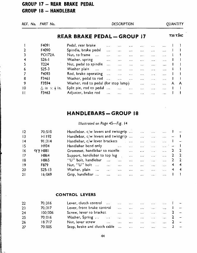
GROUP 17- REAR BRAKE PEDAL GROUP 18 - HANDLEBAR
REF. No. PART No. DESCRIPTION
I 2 3 4 5 6 7 8 9
10 ll
12 13 14 IS 16 17 18 19 20 21
22 23 24 25 26 27
REAR BRAKE PEDAL- GROUP 17
F409l F4090 POI72A S26·1 T224 S25·3 F4093 F346l F3594 } 6 in X ! in. F3463
70j510 Hll92 91/314 H934
Cfi H881 H864 H865 F879 S25·13 16j069
Pedal. rear brake Spindle, brake pedal Nut, to frame Washer, spring Nut, pedal to spindle Washer plain Rod, brake operating Washer, pedal to rod Washer, rod to pedal (for stop lamp) Split pin, rod to pedal Adjuster, brake rod
HANDLEBARS-GROUP 18
Illustrated on Page 45-Fig. 14
Handlebar, cfw levers and twistgrip ... Handlebar, cfw levers and twistgrip ... Handlebar, cjw lever brackets Handlebar bend only Grommet, handlebar to nacelle Support, handlebar to top lug "U" bolt, handlebar Nut, "U" bolt ... Washer, plain Grip, handlebar ...
CONTROL LEVERS
70;'316 Lever, clutch control
70;317 Lever, front brake control
100j006 Screw. lever to bracket
70/016 Washer, Spring ...
18/717 Nut, lever screw
70(005 Stop, brake and clutch cable
44
QUANTITY
noTioc
I I I I I
I I A A I
2 2 2 2 2 2 4 4 4 4 I I
I 2 2 2 2
HANDLEBAR- GROUP 18
1----------------·~
I i 8 9 5 6 3
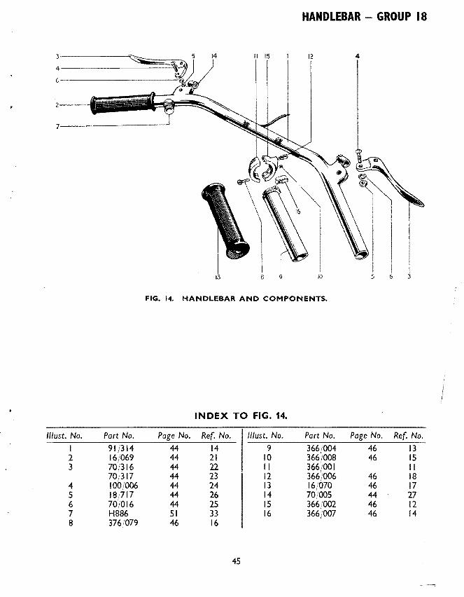
FIG. 14. HANDLEBAR AND COMPONENTS.
INDEX TO FIG. 14.
11/ust. No. Part No. No. 11/ust. No. Part No. Page No. Ref. No.
I 91/314 14 9 366/004 46 13 2 16/069 21 10 366,/008 46 IS 3 70/316 22 II 366/001 II
70/317 23 12 366/006 46 18 4 100/006 24 13 16/070 46 17 s 18/717 26 14 7010QS 44 27 6 70/016 2S IS 366/002 46 !2 7 HB86 33 16 366/007 46 14 8 3761079 16
4S

GROUP 18 - HANDLEBAR GROUP 19 - CONTROL CABLES
REf. No. PART No. DESCRIPTION QUANTITY
T20 T20C 18j763 Lever Assembly, clutch I
2 18/762 Lever Assembly, front brake 3 18j752 Lever, clutch (Ball end) 4 18j754 Lever, front brake (Ball end) 5 18/234 Bracket, lever fulcrum ... 2 6 12/040 Clamp, lever bracket 2 7 II (014 Screw, bracket, to clamp 4 8 18/087 Screw, lever pivot 2 9 18j053 Nut, pivot screw 2
TWISTGRIP
10 366/2 Twistgrip, complete II 366/001 Body, top half 12 366/002 Body, bottom half 13 366(004 Rotor 14 366(007 Spring, friction ... 15 366(008 Screw, friction spring 16 376(079 Screw, fixing 2 2 17 16j070 Grip, plastic 18 366(006 Cable stop 19 D407 Nipple, cable
CONTROL CABLES GROUP 19
FRONT BRAKE CABLE
20 D323 Cable assembly, front brake 21 D413 Cable assembly, front brake 22 DI03 Ferrule, cas1ng ... 2 2 23 18/107 Nipple (Handlebar end) 24 D81 Nipple (Handlebar end) 25 DS73 Nipple (Wheel end) 26 D279 Adjuster, cable ... 27 F879 Nut, adjuster lock 28 D280 Clevis, brake wire 29 D281 Pin, clevis 30 -fs in x l .
2 1n. Split pin, clevis pin
46

CONTROL CABLES- GROUP 19 HANDLEBAR (U.S.A.) -GROUP 20
REF. No. PART No. DESCRIPTION QUANTITY
I 2 3 4
5 6 7 8 9
10 II 12 13 14
IS 16 17
18 19 20 21 22 23 24 25
0406 12/083 0411 0407
0331 0332 0103 18/706 081 0334 0319 0268 0288 0333
H933 H934 16/069
18/557 18/556 18/528 18/234 12/040 11/014 18/087 18/053
THROTTLE CABLE
Throttle cable Ferrule, casing ... Nipple (at twistgrip) Nipple (at carburetter)
CLUTCH CABLE
Clutch cable Clutch cable Ferrule, casing Nipple (Handlebar) Nipple (Handlebar) Nipple (Clutch) Adjuster cable ... Locknut, adjuster Abutment (Handlebar) ... Abutment (Clutch)
HANDLEBAR (U.S.A.) - GROUP 20 HANDLEBAR
Handlebar cjw control lever and Twistgrip Handlebar bend only Grip, handlebar rubber
CONTROL LEVERS
Lever assembly. clutch control Lever assembly, front brake control Lever only, clutch and brake Bracket, lever fulcrum .. . Clamp, lever bracket .. . Screw, lever bracket to damp Screw, lever fulcrum Nut, lever fulcrum
TWISTGRIP and CONTROL CABLES for U.S.A. Handlebars are exactly as specified for standard T20C
47
T20 T20C
2 2
1 2 2
I 2 2 2 2 2 2 4 4 2 2 2 2
GROUP 21 - NACELLE GEAR INDICATOR
REF. No. PART No. DESCRIPTION
NACELLE GEAR INDICATOR-GROUP 21
2 3 4 5 6
7 8 9
10 II 12 13 14
Hl020 H689 H937 H939 H688 H921
0282 12J083 0285 18JII5 E3280 HIOI9 0284 H745
NACELLE GEAR INDICATOR
Rack and pinion assembly Screw, rack and pinion to nacelle l in. U.H .... Spindle assembly Finger, indicator Screw, finger to spindle-& in. U.H. Plate, gear indicator
GEAR INDICATOR CABLE
Cable assembly, gear indicator Ferrule, gear indicator casing ... Nipple. gear indicator cable (Engine end) Nipple, gear indicator casing (Indicator end) Abutment gear indicator cable cjcase ... Spring, gear indicator cable Adjuster, gear indicator cable ... Locknut, gear indicator cable adjuster
48
QUANTITY
T20 T20C
I I 2 2 I
I 2 2
2 2 I

PROPRIETARY FITTINGS
Ancillary equipment which is fitted to our motor cycles is of the highest quality and is guaranteed by the manufacturers and not by ourselves. Any repairs or claims should be sent to the actual maker, or one of their accredited agents who will always give owners every possible assistance. The following are the addresses of the various manufacturers.
CARBU RETTERS
CHAINS
ELECTRICAL EQUIPMENT
HORN ...
SPARKING PLUGS
SPEEDOMETERS
SUSPENSION UNITS
49
Zenith Carburetter Co .. Honeypot Lane, Stanmore, Middlesex.
Renold Chain, Ltd., Wythenshawe Manchester.
Messrs. J. Lucas, Ltd., Great Hampton Street, Birmingham, 18.
Messrs. Clear Hooters Ltd., Reliance Works, Bedworth, Nuneaton, Warwickshire
Champion Sparking Plugs Ltd., Feith am, Middlesex.
K.L.G. Sparking Plugs Ltd., Cricklewood Works, London, N.W.2.
Lodge Plugs Ltd .• Rugby, Warwickshire.
Messrs. Smiths Motor Accessories Ltd., Cricklewood Works, London, N.W.2.
Girling Ltd. Kings Road, Tyseley, Birmingham, II.
GROUP 22 - LUCAS ELECTRICAL EQUIPMENT
REF. No. PART No. DESCRIPTION
LUCAS ELECTRICAL EQUIPMENT- GROUP 22 ALTERNATOR (RMI3)
047SI8 Alternator assembly 2 466124 Rotor 3 468678 Stator complete 4 862898 Cable, stator output s E347S Grommet, alternator cable 6 E3204 Screw, stator to chaincase, I in. U.H. 7 El612 Washer, shakeproof 8 EIS80 Key, rotor to shaft 9 E3971 Nut, rotor to shaft
10 E40S8 Washer, rotor nut
RECTIFIER
II 47111A Rectifier 12 F3600 Nut, to frame
IGNITION COIL (MA6)
13 4S077A Coil 14 DSS7 Bolt, to bracket is in. U.H. IS Fl369 Bolt, coil and toolbox bracket, g in. U.H. 16 El612 Washer, shakeproof 17 F879 Nut, coi I bolt 18 422S67 Grommet, H.T. Cable 19 421863 Clip, H.T. cable ... 20 236741 Sleeve, L.T. cable
DISTRIBUTOR (1501)
21 40S29A Distributor 22 40610S Clamping plate assembly 23 421106 Contact set 24 421327 Condenser 2S 4237S9 Cam 26 421407 Spring set, auto advance 27 4210S6S Weight set, auto advance 28 4210S4 Shaft and action plate ... 29 41964S Sundry parts set 30 DSS7 Bolt, plate to crankcase ls in. U.H. 31 S2S-13 Washer, plain 32 E3309 Sealing ring, distributor
BATTERY (PUZSEjll)
33 408200 Battery
so
QUANTITY
T20T20C
s s s s
I I
I
I 2
2 2 2 2
2 2
----- ----
LUCAS ELECTRICAL EQUIPMENT - GROUP 22
REF. No. PART No. DESCRIPTION QUANTITY
HEADLAMP (MCF 575) no noc 1 51519A Headlamp assembly 2 516723 Rim, headlamp ... 3 500291 Wire, light unit fixing 4 4 4 516728 Light unit I 5 554946 Adaptor assembly 6 554710 Bulbholder, pilot 7 553780 Interior, pilot 8 312 Bulb, main 30j24W 9 988 Bulb, pilot 3W ...
10 H876 Adjuster screw, headlamp II H745 Locknut, adjuster screw 12 H875 Spring, adjuster screw ...
LIGHTING AND IGNITION SWITCH (P.R.S. 8) 13 31443E LIGHTING AND IGNITION SWITCH 14 318323 Grommet, for key IS 318241 Key ... 16 319333 Screw, for knob 17 318346 Knob 18 318343 Plate, index
DIPPER SWITCH 19 380521 Switch, dipper
TAIL LAMP (529) 20 53256A Lamp, tail 21 526404 Lens 22 526406 Window, number plate I 23 133551 Screw, fixing lens 2 2 24 161385 Grommet, screw ... 2 2 25 554719 Bulb holder I I 26 526408 Base, rubber I I 27 988 Bulb, 3W ... I I 28 526410 Screw, lamp to number plate 3 3 29 166103 Nut, lamp to number plate 3 3 30 188366 Washer, lamp to number plate 3 3
WIRING HARNESS 31 838121 Harness wiring ...
HORN (CLEAR HOOTER) 32 D300 Horn 33 H886 Button, horn (No. IS) ... 34 D314 Bracket, horn
51
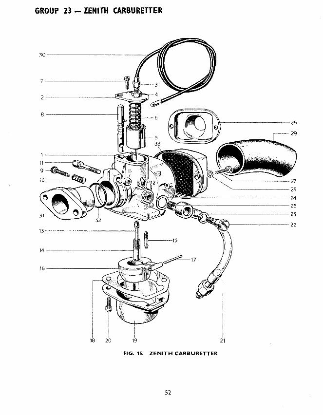
GROUP 23 - ZENITH CARBURETTER
8---------------4
11~
9~~ 10 ~
13--------------1.11
14-------------------
I 18 20 19
--------------------24 ~~~~~~.---------------------25
~r------------------23 ~--=·//
1-------------- 22
~15
21
FIG. 15. ZENITH CARBURETTER
52

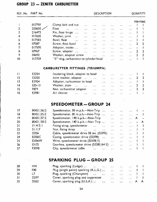
ZENITH CARBURETTER- GROUP 23
REF. No. PART No. DESCRIPTION QUANTITY
ZENITH CARBURETTER GROUP 23 TlOTIOC
I 17MXZ-CSS Carburetter cfw throttle cable I I 2 017620 Body, carburetter 3 017619 Screw, plug 4 017129 Fibre washer, large 5 017130 Gauze, filter 6 017131 Bolt, union 7 017132 Fibre washer, small 8 017133 Jet, slow running (SO) 9 017134 Jet main (78)
10 017621 Tube, emulsion ... II 017624 Slide, throttle 12 017625 Spring, throttle slide 13 017628 Slide, starter (65) 14 017759 Top, mixing chamber cfw adjuster IS 017629 Top, mixing chamber 16 07087 Screw, top to body 17 017143 Adjuster, cable ... 18 07323 Locknut, adjuster 19 017144 Screw, throttle stop 20 017156 Spring, throttle stop screw
INDEX TO FIG. 15.
//lust. No. Part No. Page No. Ref No. //lust. No. Part No. Page No. Ref No.
I 017620 53 2 18 017630 54 4 2 017629 53 IS 19 017583 54 5 3 017143 53 17 20 07087 54 6 4 07323 53 18 21 F4537 41 14 5 017624 53 II 22 017131 53 6 6 017625 53 12 23 017132 53 7 7 07087 53 16 24 017129 53 4 8 017628 53 13 25 017130 53 5 9 017144 53 19 26 017570 54 7
10 017156 53 20 27 07967 54 8 II 017797 54 I 28 04692 54 9 12 017619 53 3 29 F4469 38 29 13 017134 53 9 30 0406 47 I 14 017621 53 10 31 E3954 54 13 IS 017133 53 8 32 017729 54 10 16 220630 54 2 33 E3981 54 16 17 216472 54 3
53
GROUP 23- ZENITH CARBURETTER
REF. No. PART No.
2 3 4 5 6 7 8 9
10
017797 220630/ 216472 017630 017583 07087 017570 07967 04692 017729
Clamp bolt and nut Float Pin, float hinge Washer, joint Bowl, float Screw, float bowl Adaptor, intake .. . Screw, adaptor .. . Washer, adaptor screw
DESCRIPTION
"0" ring, carburetter to cylinder head
CARBURETTER FITTINGS (TRIUMPH)
II 12 13 14 IS 16
17 18 19 20 21 22 23 24 25 26 27
28 29 30 31 32
E3254 E3250 E3954 S25-13 F879 E3981
80421/36/2 80421/55/2 80421/37/2 80421/58/2 31/4/2/1 311111 0356 D356C D356W 0175 F3098
HN F80 L7 0297 0262
Insulating block, adaptor to head Joint washer, adaptor ... Adaptor, carbu retter to head Washer, plain Nut, carburetter adaptor Air cleaner
SPEEDOMETER-GROUP 24 Speedometer, 80 m.p.h.-Non-Trip Speedometer, 80 m.p.h.-Non-Trip Speedometer, 140 k.p.h.-Non-Trip Speedometer, 140 k.p.h.-Non Trip Fixing strap, speedometer Nut. fixing strap Cable, speedometer drive 58 ins. (53395) Casing. speedometer drive (53398) ... Wire, speedometer drive (52108/1) Gearbox, speedometer drive (52283/64;3) Clip, speedometer cable
SPARKING PLUG- GROUP 25 Plug, sparking (Lodge) ... Plug (single point) sparking (K.L.G.) ... Plug, sparking (Champion) Cover, sparking plug and suppressor Cover, sparking plug (U.S.A.) ...
54
QUANTITY
T20T20C I I l
I I
2 2
2 2 2 2
I 2 2
2 2 2 2
A
- A
I I I
A A

TWINSEAT - GROUP 26 CHAINS - GROUP 27
GIRLING SUSPENSION UNIT - GROUP 28
RE.F. No. .PART No. DESCRIPTION QUANTITY
I 2
3 4 5 6 7 8 9
10 II 12 13 14
IS 16
17 18 19 20 21 22 23 24 25 26 27 28
F4516 F4272
TWINSEAT- GROUP 26
Twinseat, cjw attachments Twinseat, cfw attachments
SPECIAL NOTE. Seat less rear bracket interchangeable :
E3181 E667A 525-3 Sl-51 F4105 F4261 El612 F879 F4361 F4129 GS299 H745
D382 o2n
Bolt, front bracket and panels to frame, 2! in. U.H. Bolt, front bracket to frame, ll ins. U.H. Washer, plain Nut, front bolt Bracket, rear Bracket, rear Washer, shakeproof Nut, bracket, to pan Safety strap twinseat Screw, strap to seat, i in. U.H. Washer, shakeproof Nut-, strap screw ...
CHAINS- GROUP 27
Chain, primary 114038, lin. X Tl'F. in. Duplex X 62 links ... Chain, rear 110044,! in. X it in. X 112 links
GIRLING SUSPENSION UNIT- GROUP 28
SC2.6/209 Suspension unit, complete SC3j204 Suspension unit, complete 9054j316A Bonded bush, top 9054j316J Bonded bush, bottom ... Fl760 Bolt, unit top, I ft in. U.H. S25-2 Washer, unit top and bottom ... POI72A Nut, unit top and bottom F4311 Bracket, unit bottom ... H622 Bolt, bracket, Iii in. U.H. F3207 Spacer, bracket bolt EI330C Washer, plain Sl-51 Nut, bracket bolt
55
TlOTlOC
I
I 2 2 2 2 A A 4 4 4 4 4 4
2 2
2 2 2 2 2 2 4 4 4 4
2
/. 2 2 2

SUPPLEMENT FOR T20S All other parts for T20S are as listed for T20C
REF. No. PART No. DESCRIPTION
I 2 3 4 5 6 7 8 9
10 II
12 13 14 15
16
17 18 19 20 21 22 23 2-4 25 26 27. 28 29 30
CPI72 E3959 E3960 E3961 E4049 E3963 E3965 E3966 E3964 E3962 E4079
Tl588 Tl565 Tl594 E4048
F4544
ENGINE - GROUP 2 Piston c jw rings, etc. (9 : I com pression ratio) ... Ring, compression ... Ring, compression (Taper) Ring, oil control Head, cylinder cjw guides and exhaust adaptor Valve, inlet ... Spring, valve inner .. . Spring, valve outer .. . Cup, valve spring bottom Camshaft, inlet and exhaust Pinion, timing and distributor drive
GEARBOX- GROUP 3 Gear duster, mainshaft Gear, mainshaft high cfw bush (27T) Gear cluster, layshaft Blanking plug, gear indicator outlet
FRAME- GROUP 5 Frame, front
TELESCOPIC FRONT FORK- GROUP 7 Hl256 Hl257 H941 S25-2 H975 HII08 Fl760 H379 Hl260 Hl280 H443 HI058 Hill? HillS
Fork assembly Middle lug and stem Bolt, middle lug pinch Washer Nut, pinch bolt Lug, fork top Bolt, top lug pinch Nut, pinch bolt Sleeve nut, fork stem Stanchion cfw bearing Bearing, stanchion lower Nut, bearing to stanch ion Bottom member, L.H. complete Bottom member, R.H. complete
56
QUANTITY
I 2 2 2
I 2 2 2
I I 2 2 2 I
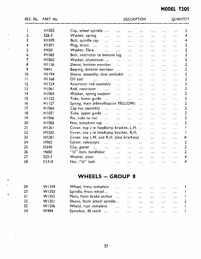
MODEL TlOS
REF. No. PART No. DESCRIPTION QUANTITY
HI053 Cap, wheel spindle 2 2 S26-3 Washer, spring 4 3 H1070 Bolt, spindle cap 4 4 HI071 Plug, drain 2 5 H430 Washer, fibre 2 6 H1063 Bolt, restrictor to bottom lug 2 7 HI062 Washer, aluminium .. 2 8 Hl126 Sleeve, bottom member 2 9 H441 Bearing, bottom member 2
10 Hl194 Sleeve, assembly, dust excluder 2 II HIJ68 Oil seal 2 12 H1124 Restrictor rod assembly 2 13 HI061 Rod, restrictor 2 14 HI060 Washer, spring support 2 iS H 1125 Tube, lower guide ... 2 16 Hl127 Spring, main (identification YELLOW) 2 17 HI064 Cap nut assembly 2 18 HI OSI Tube, upper guide 2 19 HI066 Pin, tube to nut 2 20 HI065 Nut, stanchion cap 2 21 Hl261 Cover, top cjw headlamp bracket, L.H. 22 Hl262 Cover, top cjw headlamp bracket, R.H. I 23 Hl281 Cover, top L.H. and R.H. (less brackets) A 24 H962 Gaiter, telescopic 2 25 0340 Clip, gaiter ... 2 26 H660 "U" bolt, handlebar 2 27 S25-3 Washer, plain 4 28 El310 Nut , "U" bolt 4
WHEELS- GROUP 8
29 Wl349 Wheel, front complete 20 Wl350 Spindle, front wheel. .. 31 Wl353 Plate, front brake anchor I 32 Wl351 Sleeve, front wheel spindle ... 2 33 WJ356 Wheel, rear complete 34 W984 Sprocket, 48 teeth ...
57

MODEL TlOS 15 4
14 j
5 2 28 39 3
31
12--
6
I I
8 9 10
13
27
23
18 31
35
20-;J 19
32-t 33~
36
£] 21
37
FIG. 16. TELESCOPIC FRONT FORK. T20S.
58

MODEL TlOS
INDEX TO FIG. 16
//lust. No. Part No. Page No. Ref. No.
1 H1108 56 22 2 F1760 56 23 3 H379 56 24 4 H660 57 26 5 E1310 57 28 6 H1257 56 18 7 H1260 56 25 8 H941 56 19 9 H975 56 21
10 H962 57 24 11 H1261 57 21 12 ~7H1262 57 22 13 0340 57 25 14 H1281 57 23 15 H1281 57 23 16 Not supplied separately. 17 H1117 56 29 18 H1118 56 30 19 H1071 57 4 20 H430 57 5 21 H1053 57 1 22 H1070 57 3 23 H1194 57 10 24 H1168 57 11 25 H441 57 9 26 H1126 57 8 27 H1280 56 26 28 H1065 57 20 29 H443 56 27 30 H1058 56 28 31 H1127 57 16 32 H1062 57 7 33 H1063 57 6 34 H1066 57 19 35 H1051 57 18 36 H1125 57 15 37 H1061 57 13 38 H1060 57 14 39 Steering races Page 27
59

MODEL TlOS
REF. No. PART No.
Hl269 2 Hl271 3 Hl270 4 Hl273 5 F2335 6 S25-3 7 F929 8 S25-3
DESCRIPTION
MUDGUARDS GROUP 9 Mudguard, front Stay, front Bridge, mudguard support ... Stay, lower ... Bolt, bridge and stay to fork leg Washer, plain Bolt, lower stay to fork leg Washer, plain
TOOLBOX AND AIR Fll TER - GROUP 13 9
10 II
12
13 14
15 16 17 18 19 20 21
F4550 F3858 F3859
Air filter (retained by oil tank bolts) Connection (rubber) carburetter to filter Clip, connection
PETROL AND OIL TANK - GROUP F4572 Oil tank, less fittings
HANDLEBARS GROUP 18 Hl266 Handlebar bend only 181935 Lever, assembly, front brake cfw adjuster
CONTROL CABLES - GROUP 19 D429 Cable assembly, front brake D368 Nipple, handlebar end D420 Throttle cable 12/083 Ferrule, casing DI04 Adjuster, throttle cable 6j132A Ferrule, at carburetter NS.I91 Nipple, at carbu retter
IS
QUANTITY
I 2 2 2 2
I 3
LUCAS ElECTRICAl EQUIPMENT - GROUP 22 22 54021002 Alternator assembly 23 45112A Coil (Type 2 ET) I 24 F3477 Distance tube, coil 2 25 Tl401 Screw, coil fixing 2 26 El612 Washer, shakeproof 2 27 F879 Nut ... 2 28 40664A Distributor (Type 15DI) 29 58395A Headlamp (Type M.C.H.66) 30 166 Bulb 6v 24/24 Watt, Prefocus
60

MODEL TlOS
REF. No. PART No. DESCRIPTION QUANTITY
54094090 Wiring harness 2 2 76204 Horn push (type 4A) I 3 76204 Cut-out button (type 4A) 4 53428 Tail lamp (type 529) 5 951 Bulb 6v 6W M.B.C. 6 70145 Horn (type H.F. 1950) 7 F4546 Bracket, horn (retained by coil fixing screw) 8 H688 Screw, horn to bracket 9 E2880 Washer, shakeproof
10 H691 Nut
CARBURETTER - GROUP 23 II 376/217 Carburetter, if in. choke less float chamber 12 376/031 Body, mixing chamber 13 376/055 Block, jet 14 376/067 Washer, jet block ... IS 376/070 Peg, jet block locating 16 376/155 Top, mixing chamber 17 376/065 Cap ring, mixing chamber 18 29/308 Spring, mixing chamber cap 19 4/241 Screw, cap spring 20 376/060 Valve, throttle (3 cutaway) ... 21 376/061 Spring, throttle valve 22 376/063 Needle, throttle valve 23 4/230 Clip, needle ... 24 376j072 Jet, needle (·106) 25 376/100 Jet main (140) 26 376jl40 Holder, main jet I 27 376/074 Washer, jet holder 2 28 376/075 Nut, main jet cover 29 376/076 Jet pilot (20) 30 376/095 Nut, pilot jet cover ... 31 116fl62 Washer, cover nut ... 32 332/017 Screw, air adjusting ...
61
--- - ----
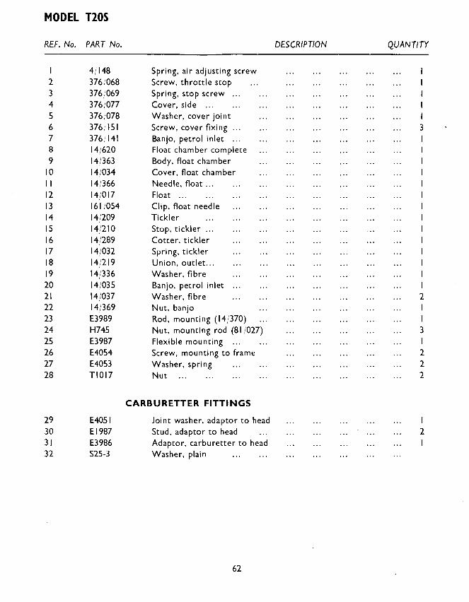
MODEL T20S
REF. No. PART No. DESCRIPTION QUANTITY
4/148 Spring, air adjusting screw 2 376}068 Screw, throttle stop 3 376/069 Spring, stop screw ... 4 376/077 Cover, side ... 5 376;078 Washer, cover joint 6 376;f51 Screw, cover fixing ... 3 7 376/141 Banjo, petrol inlet ... 8 14/620 Float chamber complete 9 14/363 Body, float chamber
10 14/034 Cover, float chamber II 14/366 Needle, float ... 12 14/017 Float ... 13 161/054 Clip, float needle 14 14/209 Tickler IS 14/210 Stop, tickler ... 16 14/289 Cotter, tickler 17 14j032 Spring, tickler 18 14/219 Union, outlet ... 19 14/336 Washer, fibre 20 14/035 Banjo, petrol inlet 21 14/037 Washer, fibre 2 22 14j369 Nut, banjo 23 E3989 Rod, mounting (14j370) 24 H745 Nut, mounting rod (81 /027) 3 25 E3987 Flexible mounting ... 26 E4054 Screw, mounting to frame 2 27 E4053 Washer, spring 2 28 TIOI7 Nut 2
CARBURETTER FITTINGS
29 E4051 Joint washer, adaptor to head 30 El987 Stud, adaptor to head 2 31 E3986 Adaptor, carbu retter to head I 32 525-3 Washer, plain
62
MODEL T20S
REF. No. PART No. DESCRIPTION QUANTITY
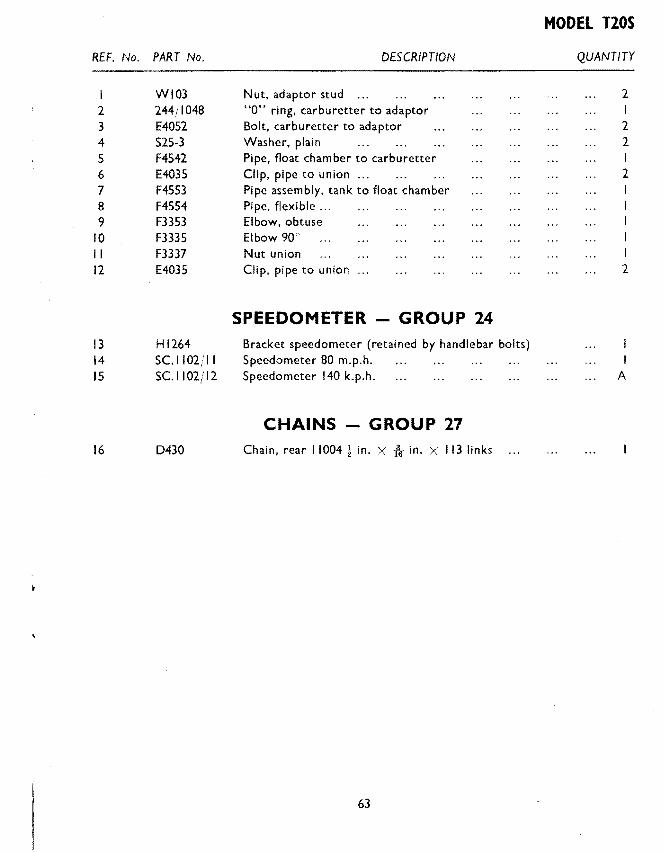
WI03 Nut, adaptor stud ... 2 2 244/ I 048 "0" ring, carburetter to adaptor 3 E4052 Bolt, carburetter to adaptor 2 4 S25-3 Washer, plain 2 5 F4542 Pipe, float chamber to carburetter I 6 E4035 Clip, pipe to union ... 2 7 F4553 Pipe assembly, tank to float chamber 8 F4554 Pipe. flexible ... 9 F3353 Elbow, obtuse
10 F3335 Elbow 90' II F3337 Nut union 12 E4035 Clip, pipe to union 2
SPEEDOMETER - GROUP 24 13 Hl264 Bracket speedometer (retained by handlebar bolts) 14 SC.II02JII Speedometer 80 m.p.h. 15 SC.II02j12 Speedometer 140 k.p.h. A
CHAINS -GROUP 27 16 D430 Chain, rear 11004! in. X -fir in. X 113 links
63

GUARANTEE
W E give the following guarantee with our motorcycles, motorcycle combinations and sidecars, including all accessories and component parts other than tyres, saddles, chains and lighting and electrical equipment, and other than accessories and
component parts supplied to the order of the Purchaser and differing from those comprised in the standard specifications supplied with our motorcycles, motorcycle combinations and sidecars, but including accessories and parts supplied by way of exchange as hereinafter provided. This guarantee is given in place of any implied conditions or warranties or any liabilities whatsoever statutory or otherwise ; no guarantee except that hereinafter contained and no conditions or warranty whatsoever statutory or otherwise is given or is to be implied, nor are we to be under any liability whatsoever except under the guarantee hereinafter contained. Any statement, description, condition or representation contained in any catalogue, advertisement, leaflet or other publication shall not be construed as enlarging, varying or overriding anything herein contained. In the case of machines (a) which have been used for "hiring out" purposes or (b) any motorcycle andjor sidecar used for any dirt track, cinder track or grass track racing or competitions (or any competition of any kind within an enclosure for which a charge is made for admission to take part in or view the competition) or (c) machines from which the trade mark, name or manufacturing number has been altered or removed or (d) any machines in which parts have been used not supplied by or approved by the motorcycle manufacturer or (e) any machine from which the silencing system as fitted by the manufacturer has been partially or wholly removed or interfered with, no guarantee, condition or warranty of any kind statutory or otherwise, is given or is to be implied, nor are we to be under any liability whatsoever in respect of any such machine. We guarantee, subject to the conditions mentioned below, that all precautions which are usual and reasonable have been taken by us to secure excellence of materials and workmanship but this guarantee is to extend and be in force for six months only in U.K. and ninety days overseas from date of purchase, or date of exchange in case of any accessory or part supplied by way of exchange as hereinafter provided, and damages for which we make ourselves responsible under this guarantee are limited to the free repair of or supply of a new part or accessory in exchange for the part of the motorcycle, motorcycle combination or sidecar or accessory which may have proved defective. We undertake, subject to the conditions mentioned below, to make good in manner aforesaid any part or accessory covered by this guarantee which has proved defective within the said period. We do not undertake to replace or refix or bear the cost of replacing or refixing any such new part or accessory in the motorcycle, motorcycle combination or sidecar. As motor~ cycles, motorcycle combinations and sidecars are easily liable to derangement by neglect or misuse, this guarantee does not apply to defects caused by wear and tear, misuse or neglect. The term "misuse" shall include, amongst others, the following acts: 1. The attaching of a sidecar to a motorcycle in such a manner as to cause damage or calculated to render the latter unsafe when ridden. 2. The use of a motorcycle or of a motorcycle and sidecar combined, when carrying more persons or a greater weight than that for which the machine was designed by the manufacturers. 3. The attaching of a sidecar to a motorcycle by any form of attachment not provided, supplied or approved by the manufacturers, or to a motorcycle which is not designed for such use. We do not guarantee tyres, saddles, chains or lighting and electrical equipment, or any accessories or component parts supplied to the order of the Purchaser differing from those comprised in the standard specifications supplied with our motorcycle combinations or sidecars. As regards all such tyres, saddles, chains, lighting and electrical equipment, accessories and component parts, no guarantee, condition or warranty of any kind statutory or otherwise is given or is to be implied, and we are to be under no liability whatsoever in respect thereof.
64
CONDITIONS OF GUARANTEE
If a defective part or accessory should be found in our motorcycles, motorcycle combinations or sidecars, or in any part or accessory supplied by way of exchange as before provided, it must be sent to us CARRIAGE PAID and accompanied by an intimation from the owner that he desires to have it repaired or exchanged free of charge under our
. guarantee, and he must also furnish us at the same time with the frame number of the machine, the date of purchase or the date when the alleged defective part or accessory was exchanged as the case may be. Failing compliance with the above, such articles will lie here at THE RISK OF THE OWNER, and this guarantee and any implied guarantee, warranty or condition shall not be enforceable.
REPAIRS
Any motorcycle, motorcycle combination or sidecar sent to us to be plated, enamelled or repaired will be repaired upon the following conditions, i.e., we guarantee that all precautions which are usual and reasonable have been taken by us to secure excellence of materials and workmanship, such guarantee to extend and be in force for three months only from the time such work shall have been executed, and this guarantee is in lieu and in exclusion of all conditions and warranties statutory or otherwise, and all liabilities whatsoever and the damages recoverable are limited to the cost of any further work which may be necessary to amend and make good the work found to be defective.
NOTE
We do not appoint agents for the sale on our behalf of our motorcycles or other goods, but we assign to motorcycle Dealers areas in which we supply to such Dealers exclusively for re-sale in such areas. No such Dealer is authorised to transact any business, give any warranty, make any representation or incur any liability on our behalf. Published retail prices are for delivery free of charge at Dealers' premises. All goods are offered for sale subject to the price ruling at time of delivery. We reserve the right to modify or deviate from the published specification.
TRIUMPH SERVICE
There are Triumph distributors and dealers in all parts ofthe world who carry adequate stocks ofTriumph parts and who are ready at all times to help and advise owners of Triumph motorcycles.
65

INDEX
Group I-CARTON PACKS
Group 2-ENGINE Crankcase ... Crankcase bearings (engine) Crankcase filter Cylinder barrel ... Cylinder head Engine sprocket Flywheels and connecting rod ..
Gasket set Inner cover, left side Inner cover, right side ... Oil pumps Overhead rocker and covers Outer cover, left side .. . Outer cover, right side .. . Piston Push rods and cover Rocker oil pipe ... Tappets ... Timing gears and camshaft Valves, guides and springs
Group 3-GEARBOX AND CLUTCH Camplate ... Clutch Clutch control Filler, level and drain plugs Gearbox casing bearings Gearbox sprocket Gearbox change mechanism Kickstarter Selector forks and spindle Shafts and gears
Group 4-EXHAUST SYSTEM
Group 5-FRAME ...
66
Page No.
5
6 8 8 9
6 6 9 7
12 9
12 8 6 9
12 6 7 7 7 8 7
13 13 15 16 15 14 15 13 15 13 13
18
18
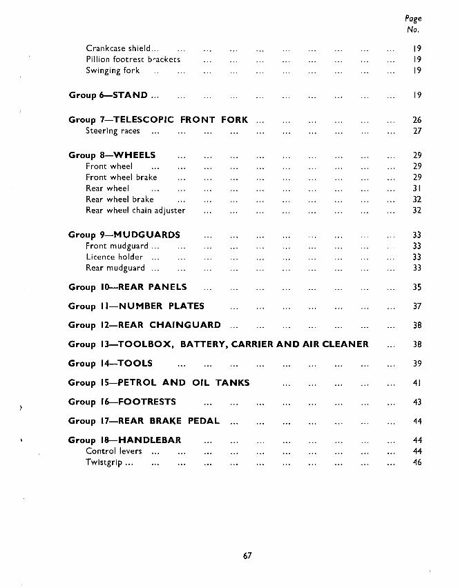
Crankcase shield ... Pillion footrest brackets Swinging fork
Group 6-STAND ...
Group 7-TELESCOPIC FRONT FORK Steering races
Group 8-WHEELS Front wheel Front wheel brake Rear wheel Rear wheel brake Rear wheel chain adjuster
Group 9-MUDGUARDS Front mudguard ... Licence holder Rear mudguard ...
Group 10-REAR PANELS
Group II-NUMBER PLATES
Group 12-REAR CHAINGUARD
Group 13-TOOLBOX, BATTERY, CARRIER AND AIR CLEANER
Group 14-TOOLS
Group IS-PETROL AND OIL TANKS
Group 16-FOOTRESTS
Group 17-REAR BRAKE PEDAL
Group IS-HANDLEBAR Control levers Twistgrip ...
67
Page No.
19 19 19
19
26 27
29 29 29 31 32 32
33 33 33 33
35
37
38
38
39
41
43
44
44 44 46

Group 19-CONTROL CABLES Clutch cable Front brake cable Throttle cable
Group 20-HANDLEBAR (U.S.A.) ...
Group 21-NACELLE GEAR INDICATOR
PROPRIETARY FITTINGS
Group 22-LUCAS ELECTRICAL EQUIPMENT Alternator Battery ... Dipper switch Distributor Head lamp Horn Ignition Coil Lighting and ignition switch Rectifier ... Tail lamp Wiring harness ...
Group 23-ZENITH CARBURETTER
Group 24-SPEEDOMETER
Group 25-SPARKING PLUG
Group 26-TWI NSEA T
Group 27-CHAI NS
Group 28-GIRLING SUSPENSION UNITS
Supplement for T20S
68
46 47 46 47
47
48
50 50 so 51 50 51 51 so 51 50 51 51
53
54
54
55
55
55
56
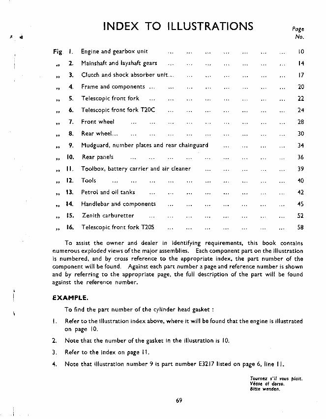
~ .. INDEX TO ILLUSTRATIONS Page No.
Fig. I. Engine and gearbox unit 10
.. 2. Mainshaft and layshaft gears 14
.. 3. Clutch and shock absorber unit ... 17
.. 4. Frame and components 20
" 5. Telescopic front fork 22
" 6. Telescopic front fork T20C 24
.. 1. Front wheel 28
.. 8. Rear wheel. .. 30
.. 9. Mudguard, number plates and rear chainguard 34
.. 10. Rear panels 36
.. II. Toolbox, battery carrier and air cleaner 39
•• 12. Tools 40
.. 13. Petrol and oil tanks 42
.. 14. Handlebar and components 45
.. 15. Zenith carburetter 52
, 16. Telescopic front fork T20S 58
To assist the owner and dealer in identifying requirements, this book contains numerous exploded views oft he major assemblies. Each component part on the illustration is numbered, and by cross reference to the appropriate index, the part number of the component will be found. Against each part number a page and reference number is shown and by referring to the appropriate page, the full description of the part will be found against the reference number.
EXAMPLE.
To find the part number of the cylinder head gasket :
I. Refer to the illustration index above, where it will be found that the engine is illustrated on page 10.
2. Note that the number of the gasket in the illustration is I 0.
3. Refer to the index on page II.
4. Note that illustration number 9 is part number E3217 listed on page 6, line II.
69
Tournez s'il vous plait. Vease a/ dorsa. 8itte wenden.
MANif:RE D'IDENTIFIER LA Plf:CE DE RECHANGE REQUISE Afin d'assister MM. les marchands et MM. les possesseurs a !'identification des pieces de rechange,
ce livre contient de nombreuses illustrations des montages principaux en fa~on de "perspectives eclatees". Chaque piece composante a !'illustration est numerotee ; en se referant a !'index approprie on peut
trouver le numero relatif. A cote de chaque piece illustree se trouve le numero de Ia page et le numero de reference ; en se
referant a Ia page approprie Ia description complete de Ia piece sera facilement constate.
Ex em pie. Pour identifier le numero de reference du joint de culasse : I. Se referer a Ia page intitulee "Index to Illustrations" ou on trouvera que le moteur est illustree
sur Ia page 10. 2. Noter qu'a cote du joint de culasse se trouve le numero 10. 3. Se referer a !'index donne sur Ia page numero II. 4. On y constatera que suivant le numero 9 se trouve :
(a) le numero relatif-E.3217 (b) le numero de Ia page d'index-6 (c) Ia ligne de reference-! I.
MANERA DE ENCONTRAR LA PIEZA DESEADA Para ayudar al propietario y al representante en Ia identificaci6n de las piezas deseadas este libro
contiene numerosas ilustraciones de los principales montages. Cada pieza componente en Ia ilustraci6n esti. numerada y al referirse al indice apropiada, se encontrara
el numero de Ia pieza. · Contra el numero de cada pieza se muestra el numero de referenda, y al referirse a Ia pagina apropiada
a descripcion completa de cada pieza se encontrara contra el numero de referenda.
Ejemplo. Para encontrar el numero de pieza de Ia empaquetadura de Ia culata de cilindro : I. Referirse a Ia pagina "Index to Illustrations" donde se vera que Ia ilustraci6n del motor esta en
Ia pagina 10. ' 2. N6tese que el numero de Ia empaquetadura en Ia ilustraci6n es 10. 3. Referirse al indice de Ia ilustraci6n en question en Ia pagina II. 4. Notese que no. 9 es pieza numero E.3217 en Ia lista de Ia pagina 6, linea de referenda no. II.
ANWEISUNG ZUR IDENTIFIZIERUNG BENOETIGTER ERSATZTEILE Dieses Buch enthalt zahlreiche Zerlege-Abbildungen der Hauptzusammenstellungen, un dem Besiter
und dem Verteiler beim lndentifizieren seiner Forderungen zu helfen. Jedes Teil auf der Abbildung ist mit einer Nummer versehen, und die Bestandteilnummer wird durch Nachschlagen des beztiglichen Verzeichnisses gefunden. Mit jeder Teilnummer ist die seite und die Referenznummer gegeben, und durch Nachschlagen der bezuglichen Seite wird die vollstandige Beschreibung des Teiles unter de Referenznummer gefunden.
Zum Beispiel. Um die Nummer der Zylinderkopfdichtung zu finden : I. Schlagen Sie das Abbildungverzeichnis, oben, nach, wo es gefunden wird, dass die Maschine auf
Seite 10 abgebildet ist. 2. Merken Sie, dass Nr. 10 ist die Nummer der Dichtung auf der Abbildung. 3. Schlagen Sie das Verzeichn is auf Seite II, nach. 'I. Merken Sie, dass die Abbildungnummer 9 ist die Teilnummer E.3217, eingetragen auf Seite 6.
Zelle II.
70