Embed Size (px)
Citation preview
TIA STANDARD
Telecommunications Infrastructure Standard for Data Centers
TIA-942 April 2005 TELECOMMUNICATIONS INDUSTRY ASSOCIATION
Representing the telecommunications industry in association with the Electronic Industries Alliance
ANSI/TIA-942-2005
Approved: April 12, 2005

NOTICE TIA Engineering Standards and Publications are designed to serve the public interest through eliminating misunderstandings between manufacturers and purchasers, facilitating interchangeability and improvement of products, and assisting the purchaser in selecting and obtaining with minimum delay the proper product for their particular need. The existence of such Standards and Publications shall not in any respect preclude any member or non-member of TIA from manufacturing or selling products not conforming to such Standards and Publications. Neither shall the existence of such Standards and Publications preclude their voluntary use by Non-TIA members, either domestically or internationally. Standards and Publications are adopted by TIA in accordance with the American National Standards Institute (ANSI) patent policy. By such action, TIA does not assume any liability to any patent owner, nor does it assume any obligation whatever to parties adopting the Standard or Publication. This Standard does not purport to address all safety problems associated with its use or all applicable regulatory requirements. It is the responsibility of the user of this Standard to establish appropriate safety and health practices and to determine the applicability of regulatory limitations before its use. (From Standards Proposal No. 3-0092-C-1, formulated under the cognizance of the TIA TR-42.1, Subcommittee on Commercial Building Telecommunications Cabling).
Published by
©TELECOMMUNICATIONS INDUSTRY ASSOCIATION Standards and Technology Department 2500 Wilson Boulevard Arlington, VA 22201 U.S.A.
PRICE: Please refer to current Catalog of TIA TELECOMMUNICATIONS INDUSTRY ASSOCIATION STANDARDS
AND ENGINEERING PUBLICATIONS or call Global Engineering Documents, USA and Canada
(1-800-854-7179) International (303-397-7956) or search online at http://www.tiaonline.org/standards/search_n_order.cfm
All rights reserved Printed in U.S.A.

NOTICE OF COPYRIGHT
This document is copyrighted by the TIA.
Reproduction of these documents either in hard copy or soft copy (including posting on the web) is prohibited without copyright permission. For copyright permission to reproduce portions of this document, please contact TIA Standards Department or go to the TIA website (www.tiaonline.org) for details on how to request permission. Details are located at:
http://www.tiaonline.org/about/faqDetail.cfm?id=18
OR
Telecommunications Industry Association Standards & Technology Department
2500 Wilson Boulevard, Suite 300 Arlington, VA 22201 USA
+1(703)907-7700
Organizations may obtain permission to reproduce a limited number of copies by entering into a license agreement. For information, contact:
Global Engineering Documents
15 Inverness Way East Englewood, CO 80112-5704 or call
U.S.A. and Canada (1-800-854-7179) International (303) 397-7956

NOTICE OF DISCLAIMER AND LIMITATION OF LIABILITY
The document to which this Notice is affixed (the “Document”) has been prepared by one or more Engineering Committees or Formulating Groups of the Telecommunications Industry Association (“TIA”). TIA is not the author of the Document contents, but publishes and claims copyright to the Document pursuant to licenses and permission granted by the authors of the contents.
TIA Engineering Committees and Formulating Groups are expected to conduct their affairs in accordance with the TIA Engineering Manual (“Manual”), the current and predecessor versions of which are available at http://www.tiaonline.org/standards/sfg/engineering_manual.cfm. TIA’s function is to administer the process, but not the content, of document preparation in accordance with the Manual and, when appropriate, the policies and procedures of the American National Standards Institute (“ANSI”). TIA does not evaluate, test, verify or investigate the information, accuracy, soundness, or credibility of the contents of the Document. In publishing the Document, TIA disclaims any undertaking to perform any duty owed to or for anyone.
If the Document is identified or marked as a project number (PN) document, or as a standards proposal (SP) document, persons or parties reading or in any way interested in the Document are cautioned that: (a) the Document is a proposal; (b) there is no assurance that the Document will be approved by any Committee of TIA or any other body in its present or any other form; (c) the Document may be amended, modified or changed in the standards development or any editing process.
The use or practice of contents of this Document may involve the use of intellectual property rights (“IPR”),
including pending or issued patents, or copyrights, owned by one or more parties. TIA makes no search or investigation for IPR. When IPR consisting of patents and published pending patent applications are claimed and called to TIA’s attention, a statement from the holder thereof is requested, all in accordance with the Manual. TIA takes no position with reference to, and disclaims any obligation to investigate or inquire into, the scope or validity of any claims of IPR. TIA will neither be a party to discussions of any licensing terms or conditions, which are instead left to the parties involved, nor will TIA opine or judge whether proposed licensing terms or conditions are reasonable or non-discriminatory. TIA does not warrant or represent that procedures or practices suggested or provided in the Manual have been complied with as respects the Document or its contents. TIA does not enforce or monitor compliance with the contents of the Document. TIA does not certify, inspect, test or otherwise investigate products, designs or services or any claims of compliance with the contents of the Document.
ALL WARRANTIES, EXPRESS OR IMPLIED, ARE DISCLAIMED, INCLUDING WITHOUT LIMITATION, ANY AND ALL WARRANTIES CONCERNING THE ACCURACY OF THE CONTENTS, ITS FITNESS OR APPROPRIATENESS FOR A PARTICULAR PURPOSE OR USE, ITS MERCHANTABILITY AND ITS NON-INFRINGEMENT OF ANY THIRD PARTY’S INTELLECTUAL PROPERTY RIGHTS. TIA EXPRESSLY DISCLAIMS ANY AND ALL RESPONSIBILITIES FOR THE ACCURACY OF THE CONTENTS AND MAKES NO REPRESENTATIONS OR WARRANTIES REGARDING THE CONTENT’S COMPLIANCE WITH ANY APPLICABLE STATUTE, RULE OR REGULATION, OR THE SAFETY OR HEALTH EFFECTS OF THE CONTENTS OR ANY PRODUCT OR SERVICE REFERRED TO IN THE DOCUMENT OR PRODUCED OR RENDERED TO COMPLY WITH THE CONTENTS. TIA SHALL NOT BE LIABLE FOR ANY AND ALL DAMAGES, DIRECT OR INDIRECT, ARISING FROM OR RELATING TO ANY USE OF THE CONTENTS CONTAINED HEREIN, INCLUDING WITHOUT LIMITATION ANY AND ALL INDIRECT, SPECIAL, INCIDENTAL OR CONSEQUENTIAL DAMAGES (INCLUDING DAMAGES FOR LOSS OF BUSINESS, LOSS OF PROFITS, LITIGATION, OR THE LIKE), WHETHER BASED UPON BREACH OF CONTRACT, BREACH OF WARRANTY, TORT (INCLUDING NEGLIGENCE), PRODUCT LIABILITY OR OTHERWISE, EVEN IF ADVISED OF THE POSSIBILITY OF SUCH DAMAGES. THE FOREGOING NEGATION OF DAMAGES IS A FUNDAMENTAL ELEMENT OF THE USE OF THE CONTENTS HEREOF, AND THESE CONTENTS WOULD NOT BE PUBLISHED BY TIA WITHOUT SUCH LIMITATIONS.

TIA–942
1
Telecommunications Infrastructure Standard
for Data Centers Table of Contents
FOREWORD ................................................................................................................................... 8
1 SCOPE ................................................................................................................................ 12
1.1 General............................................................................................................................ 12 1.2 Normative references...................................................................................................... 12
2 DEFINITION OF TERMS, ACRONYMS AND ABBREVIATIONS, AND UNITS OF MEASURE........................................................................................................................... 13
2.1 General............................................................................................................................ 13 2.2 Definition of terms ........................................................................................................... 13 2.3 Acronyms and abbreviations........................................................................................... 17 2.4 Units of measure ............................................................................................................. 19
3 DATA CENTER DESIGN OVERVIEW................................................................................ 20
3.1 General............................................................................................................................ 20 3.2 Relationship of data center spaces to other building spaces.......................................... 20 3.3 Tiering ............................................................................................................................. 21 3.4 Consideration for involvement of professionals .............................................................. 21
4 DATA CENTER CABLING SYSTEM INFRASTRUCTURE ............................................... 22
4.1 The basic elements of the data center cabling system structure.................................... 22
5 DATA CENTER TELECOMMUNICATIONS SPACES AND RELATED TOPOLOGIES... 23
5.1 General............................................................................................................................ 23 5.2 Data center structure....................................................................................................... 23
5.2.1 Major elements ........................................................................................................ 23 5.2.2 Typical data center topology.................................................................................... 24 5.2.3 Reduced data center topologies .............................................................................. 24 5.2.4 Distributed data center topologies ........................................................................... 25
5.3 Computer room requirements ......................................................................................... 26 5.3.1 General .................................................................................................................... 26 5.3.2 Location ................................................................................................................... 27 5.3.3 Access ..................................................................................................................... 27 5.3.4 Architectural design ................................................................................................. 27
5.3.4.1 Size ....................................................................................................................................27 5.3.4.2 Guidelines for other equipment ..........................................................................................27 5.3.4.3 Ceiling height .....................................................................................................................27 5.3.4.4 Treatment...........................................................................................................................27 5.3.4.5 Lighting...............................................................................................................................28 5.3.4.6 Doors .................................................................................................................................28 5.3.4.7 Floor loading ......................................................................................................................28 5.3.4.8 Signage..............................................................................................................................28 5.3.4.9 Seismic considerations ......................................................................................................28
5.3.5 Environmental design .............................................................................................. 28 5.3.5.1 Contaminants .....................................................................................................................28 5.3.5.2 HVAC .................................................................................................................................29

TIA-942
2
5.3.5.2.1 Continuous operation ...................................................................................................29 5.3.5.2.2 Standby operation ........................................................................................................29
5.3.5.3 Operational parameters .....................................................................................................29 5.3.5.4 Batteries .............................................................................................................................29 5.3.5.5 Vibration .............................................................................................................................29
5.3.6 Electrical design....................................................................................................... 30 5.3.6.1 Power .................................................................................................................................30 5.3.6.2 Standby power ...................................................................................................................30 5.3.6.3 Bonding and grounding (earthing)......................................................................................30
5.3.7 Fire protection .......................................................................................................... 30 5.3.8 Water infiltration ....................................................................................................... 30
5.4 Entrance room requirements........................................................................................... 30 5.4.1 General .................................................................................................................... 30 5.4.2 Location ................................................................................................................... 31 5.4.3 Quantity.................................................................................................................... 31 5.4.4 Access ..................................................................................................................... 31 5.4.5 Entrance conduit routing under access floor ........................................................... 31 5.4.6 Access provider and service provider spaces ......................................................... 31 5.4.7 Building entrance terminal ....................................................................................... 32
5.4.7.1 General ..............................................................................................................................32 5.4.8 Architectural design ................................................................................................. 32
5.4.8.1 General ..............................................................................................................................32 5.4.8.2 Size ....................................................................................................................................32 5.4.8.3 Plywood backboards ..........................................................................................................33 5.4.8.4 Ceiling height .....................................................................................................................33 5.4.8.5 Treatment...........................................................................................................................33 5.4.8.6 Lighting...............................................................................................................................33 5.4.8.7 Doors .................................................................................................................................33 5.4.8.8 Signage..............................................................................................................................33 5.4.8.9 Seismic considerations ......................................................................................................33 5.4.8.10 HVAC .............................................................................................................................34
5.4.8.10.1 Continuous operation .................................................................................................34 5.4.8.10.2 Standby operation ......................................................................................................34
5.4.8.11 Operational parameters..................................................................................................34 5.4.8.12 Power .............................................................................................................................34 5.4.8.13 Standby Power...............................................................................................................35 5.4.8.14 Bonding and grounding ..................................................................................................35
5.4.9 Fire protection .......................................................................................................... 35 5.4.10 Water infiltration ....................................................................................................... 35
5.5 Main distribution area...................................................................................................... 35 5.5.1 General .................................................................................................................... 35 5.5.2 Location ................................................................................................................... 35 5.5.3 Facility requirements................................................................................................ 35
5.6 Horizontal distribution area ............................................................................................. 36 5.6.1 General .................................................................................................................... 36 5.6.2 Location ................................................................................................................... 36 5.6.3 Facility requirements................................................................................................ 36
5.7 Zone distribution area ..................................................................................................... 36 5.8 Equipment distribution areas .......................................................................................... 37 5.9 Telecommunications room.............................................................................................. 37 5.10 Data center support areas............................................................................................... 37 5.11 Racks and cabinets......................................................................................................... 37
5.11.1 General .................................................................................................................... 37 5.11.2 "Hot" and "cold" aisles ............................................................................................. 38 5.11.3 Equipment placement .............................................................................................. 38 5.11.4 Placement relative to floor tile grid........................................................................... 39 5.11.5 Access floor tile cuts ................................................................................................ 39 5.11.6 Installation of racks on access floors ....................................................................... 39

TIA–942
3
5.11.7 Specifications........................................................................................................... 39 5.11.7.1 Clearances .....................................................................................................................39 5.11.7.2 Cabinet ventilation..........................................................................................................40 5.11.7.3 Cabinet and rack height .................................................................................................40 5.11.7.4 Cabinet depth and width.................................................................................................40 5.11.7.5 Adjustable rails...............................................................................................................40 5.11.7.6 Rack and cabinet finishes ..............................................................................................41 5.11.7.7 Power strips ...................................................................................................................41 5.11.7.8 Additional cabinet and rack specifications......................................................................41
5.11.8 Racks and cabinets in entrance room, main distribution areas and horizontal distribution areas .................................................................................................................... 41
6 DATA CENTER CABLING SYSTEMS ............................................................................... 43
6.1 General............................................................................................................................ 43 6.2 Horizontal Cabling........................................................................................................... 43
6.2.1 General .................................................................................................................... 43 6.2.2 Topology .................................................................................................................. 44 6.2.3 Horizontal cabling distances .................................................................................... 44
6.2.3.1 Maximum lengths for copper cabling..................................................................................45 6.2.4 Recognized media ................................................................................................... 45
6.3 Backbone cabling............................................................................................................ 46 6.3.1 General .................................................................................................................... 46 6.3.2 Topology .................................................................................................................. 47
6.3.2.1 Star topology ......................................................................................................................47 6.3.2.2 Accommodation of non-star configurations ........................................................................47
6.3.3 Redundant cabling topologies ................................................................................. 47 6.3.4 Recognized media ................................................................................................... 48 6.3.5 Backbone cabling distances .................................................................................... 48
6.4 Choosing media .............................................................................................................. 49 6.5 Centralized optical fiber cabling ...................................................................................... 50
6.5.1 Introduction .............................................................................................................. 50 6.5.2 Guidelines ................................................................................................................ 50
6.6 Cabling transmission performance and test requirements ............................................. 51
7 DATA CENTER CABLING PATHWAYS............................................................................ 52
7.1 General............................................................................................................................ 52 7.2 Security for data center cabling ...................................................................................... 52 7.3 Separation of power and telecommunications cables .................................................... 52
7.3.1 Separation between electrical power and twisted-pair cables................................. 52 7.3.2 Practices to accommodate power separation requirements.................................... 53 7.3.3 Separation of fiber and copper cabling.................................................................... 54
7.4 Telecommunications entrance pathways........................................................................ 54 7.4.1 Entrance pathway types .......................................................................................... 54 7.4.2 Diversity ................................................................................................................... 54 7.4.3 Sizing ....................................................................................................................... 54
7.5 Access floor systems ...................................................................................................... 54 7.5.1 General .................................................................................................................... 54 7.5.2 Cable trays for telecommunications cabling ............................................................ 55 7.5.3 Access floor performance requirements.................................................................. 55 7.5.4 Floor tile cut edging.................................................................................................. 55 7.5.5 Cable types under access floors.............................................................................. 55
7.6 Overhead cable trays ...................................................................................................... 56 7.6.1 General .................................................................................................................... 56 7.6.2 Cable tray support.................................................................................................... 56 7.6.3 Coordination of cable tray routes............................................................................. 56
8 DATA CENTER REDUNDANCY ........................................................................................ 57

TIA-942
4
8.1 Introduction ..................................................................................................................... 57 8.2 Redundant maintenance holes and entrance pathways................................................. 57 8.3 Redundant access provider services .............................................................................. 58 8.4 Redundant entrance room .............................................................................................. 58 8.5 Redundant main distribution area ................................................................................... 58 8.6 Redundant backbone cabling ......................................................................................... 59 8.7 Redundant horizontal cabling ......................................................................................... 59
ANNEX A (INFORMATIVE) CABLING DESIGN CONSIDERATIONS ....................................... 60
A.1 Cabling application distances ......................................................................................... 60 A.1.1 T-1, E-1, T-3 and E-3 circuit distances .................................................................... 61 A.1.2 EIA/TIA-232 and EIA/TIA-561 console connections................................................ 64 A.1.3 Other application distances ..................................................................................... 64
A.2 Cross-connections .......................................................................................................... 64 A.3 Separation of functions in the main distribution area...................................................... 64
A.3.1 Twisted-pair main cross-connect ............................................................................. 64 A.3.2 Coaxial main cross-connect..................................................................................... 65 A.3.3 Optical fiber main cross-connect ............................................................................. 65
A.4 Separation of functions in the horizontal distribution area .............................................. 65 A.5 Cabling to telecommunications equipment ..................................................................... 65 A.6 Cabling to end equipment ............................................................................................... 66 A.7 Fiber design consideration.............................................................................................. 66 A.8 Copper design consideration .......................................................................................... 66
ANNEX B (INFORMATIVE) TELECOMMUNICATIONS INFRASTRUCTURE ADMINISTRATION.............................................................................................................. 67
B.1 General............................................................................................................................ 67 B.2 Identification scheme for floor space .............................................................................. 67 B.3 Identification scheme for racks and cabinets .................................................................. 67 B.4 Identification scheme for patch panels............................................................................ 68 B.5 Cable and patch cord identifier ....................................................................................... 70
ANNEX C (INFORMATIVE) ACCESS PROVIDER INFORMATION........................................... 72
C.1 Access provider coordination.......................................................................................... 72 C.1.1 General .................................................................................................................... 72 C.1.2 Information to provide to access providers.............................................................. 72 C.1.3 Information that the access providers should provide ............................................. 72
C.2 Access provider demarcation in the entrance room ....................................................... 73 C.2.1 Organization............................................................................................................. 73 C.2.2 Demarcation of low-speed circuits........................................................................... 73 C.2.3 Demarcation of T-1 circuits...................................................................................... 76 C.2.4 Demarcation of E-3 & T-3 circuits............................................................................ 76 C.2.5 Demarcation of optical fiber circuits......................................................................... 77
ANNEX D (INFORMATIVE) COORDINATION OF EQUIPMENT PLANS WITH OTHER ENGINEERS........................................................................................................................ 78
D.1 General............................................................................................................................ 78
ANNEX E (INFORMATIVE) DATA CENTER SPACE CONSIDERATIONS ............................... 79
E.1 General............................................................................................................................ 79
ANNEX F (INFORMATIVE) SITE SELECTION........................................................................... 80
F.1 General............................................................................................................................ 80 F.2 Architectural site selection considerations ...................................................................... 80 F.3 Electrical site selection considerations ........................................................................... 81 F.4 Mechanical site selection considerations........................................................................ 81

TIA–942
5
F.5 Telecommunications site selection considerations......................................................... 82 F.6 Security site selection considerations ............................................................................. 82 F.7 Other site selection considerations ................................................................................. 82
ANNEX G (INFORMATIVE) DATA CENTER INFRASTRUCTURE TIERS ................................ 84
G.1 General................................................................................................................................ 84 G.1.1 Redundancy overview .................................................................................................. 84 G.1.2 Tiering overview ........................................................................................................... 84
G.2 Redundancy .................................................................................................................... 85 G.2.1 N - Base requirement............................................................................................... 85 G.2.2 N+1 redundancy ...................................................................................................... 85 G.2.3 N+2 redundancy ...................................................................................................... 85 G.2.4 2N redundancy......................................................................................................... 85 G.2.5 2(N+1) redundancy .................................................................................................. 85 G.2.6 Concurrent maintainability and testing capability .................................................... 85 G.2.7 Capacity and scalability ........................................................................................... 85 G.2.8 Isolation.................................................................................................................... 85 G.2.9 Data center tiering.................................................................................................... 85
G.2.9.1 General ..............................................................................................................................85 G.2.9.2 Tier 1 data center – basic...................................................................................................86 G.2.9.3 Tier 2 data center – redundant components.......................................................................87 G.2.9.4 Tier 3 data center - concurrently maintainable ...................................................................87 G.2.9.5 Tier 4 data center - fault tolerant ........................................................................................87
G.3 Telecommunications systems requirements................................................................... 88 G.3.1 Telecommunications tiering ..................................................................................... 88
G.3.1.1 Tier 1 (telecommunications) ...............................................................................................88 G.3.1.2 Tier 2 (telecommunications) ...............................................................................................88 G.3.1.3 Tier 3 (telecommunications) ...............................................................................................89 G.3.1.4 Tier 4 (telecommunications) ...............................................................................................90
G.4 Architectural and structural requirements ....................................................................... 91 G.4.1 General .................................................................................................................... 91 G.4.2 Architectural tiering .................................................................................................. 92
G.4.2.1 Tier 1 (architectural) ...........................................................................................................92 G.4.2.2 Tier 2 (architectural) ...........................................................................................................92 G.4.2.3 Tier 3 (architectural) ...........................................................................................................92 G.4.2.4 Tier 4 (architectural) ...........................................................................................................93
G.5 Electrical systems requirements ..................................................................................... 94 G.5.1 General electrical requirements............................................................................... 94
G.5.1.1 Utility service entrance and primary distribution .................................................................94 G.5.1.2 Standby generation ............................................................................................................94 G.5.1.3 Uninterruptible power supply (UPS) ...................................................................................95 G.5.1.4 Computer power distribution ..............................................................................................97 G.5.1.5 Building grounding and lightning protection systems .........................................................98 G.5.1.6 Data center grounding infrastructure. .............................................................................99 G.5.1.7 Computer or telecommunications rack or frame grounding..............................................100
G.5.1.7.1 The rack framework grounding conductor ....................................................................100 G.5.1.7.2 Rack grounding connection point .................................................................................100 G.5.1.7.3 Bonding to the rack ......................................................................................................100 G.5.1.7.4 Bonding to the data center grounding infrastructure.....................................................100 G.5.1.7.5 Rack continuity .............................................................................................................100
G.5.1.8 Rack-mounted equipment grounding ..................................................................................102 G.5.1.8.1 Grounding the equipment chassis ................................................................................102 G.5.1.8.2 Grounding through the equipment ac (alternating current) power cables.....................102
G.5.1.9 Electro static discharge wrist straps ....................................................................................103 G.5.1.10 Building management system ...........................................................................................103
G.5.2 Electrical tiering...................................................................................................... 103 G.5.2.1 Tier 1 (electrical) ..............................................................................................................103 G.5.2.2 Tier 2 (electrical) ..............................................................................................................104 G.5.2.3 Tier 3 (electrical) ..............................................................................................................104

TIA-942
6
G.5.2.4 Tier 4 (electrical) ..............................................................................................................105 G.6 Mechanical systems requirements................................................................................ 106
G.6.1 General mechanical requirements......................................................................... 106 G.6.1.1 Environmental air ............................................................................................................106 G.6.1.2 Ventilation air ..................................................................................................................106 G.6.1.3 Computer room air conditioning ......................................................................................106 G.6.1.4 Leak detection system ....................................................................................................107 G.6.1.5 Building management system .........................................................................................107 G.6.1.6 Plumbing systems ...........................................................................................................107 G.6.1.7 Emergency fixtures .........................................................................................................107 G.6.1.8 HVAC make-up water .....................................................................................................107 G.6.1.9 Drainage piping ...............................................................................................................107 G.6.1.10 Fire protection systems ................................................................................................108 G.6.1.11 Water suppression – pre-action suppression ...............................................................109 G.6.1.12 Gaseous suppression - clean agent fire suppression...................................................109 G.6.1.13 Hand held fire extinguishers.........................................................................................110
G.6.2 Mechanical tiering.................................................................................................. 110 G.6.2.1 Tier 1 (mechanical) .........................................................................................................110 G.6.2.2 Tier 2 (mechanical) .........................................................................................................110 G.6.2.3 Tier 3 (mechanical) .........................................................................................................111 G.6.2.4 Tier 4 (mechanical) .........................................................................................................112
ANNEX H (INFORMATIVE) DATA CENTER DESIGN EXAMPLES......................................... 131
H.1 Small data center design example................................................................................ 131 H.2 Corporate data center design example......................................................................... 132 H.3 Internet data center design example............................................................................. 133
ANNEX I (INFORMATIVE) BIBLIOGRAPHY AND REFERENCES........................................ 135

TIA–942
7
List of figures
Figure 1: Relationship of spaces in a data center ......................................................................... 21 Figure 2: Data center topology ...................................................................................................... 22 Figure 3: Example of a basic data center topology ....................................................................... 24 Figure 4: Example of a reduced data center topology................................................................... 25 Figure 5: Example of a distributed data center topology with multiple entrance rooms................ 26 Figure 6: Example of "hot" aisles, "cold" aisles and cabinet placement........................................ 38 Figure 7: Typical horizontal cabling using a star topology ............................................................ 44 Figure 8: Typical backbone cabling using a star topology ............................................................ 47 Figure 9: Centralized optical fiber cabling ..................................................................................... 50 Figure 10: Telecommunications infrastructure redundancy .......................................................... 57 Figure 11: Sample floor space identifiers ...................................................................................... 67 Figure 12: Sample rack/cabinet identifier ...................................................................................... 68 Figure 13: Sample copper patch panel identification schema....................................................... 69 Figure 14: Sample 8-position modular patch panel labeling – Part I............................................. 70 Figure 15: Sample 8-position modular patch panel labeling – Part II............................................ 70 Figure 16: Cross-connection circuits to IDC connecting hardware cabled to modular jacks in
the T568A 8-pin sequence .......................................................................................... 74 Figure 17: Cross-connection circuits to IDC connecting hardware cabled to modular jacks in
the T568B 8-pin sequence .......................................................................................... 75 Figure 18: American standard internal-external tooth lock washer ............................................. 101 Figure 19: Typical rack assembly hardware................................................................................ 102 Figure 20: Computer room layout showing “hot” and “cold” aisles.............................................. 131 Figure 21: Example for corporate data center............................................................................. 132 Figure 22: Example for internet data center ................................................................................ 133
List of tables
Table 1: Maximum length of horizontal and equipment area cables............................................. 45 Table 2: Data center separation between twisted-pair and shielded power cables ...................... 53 Table 3: Maximum circuit distances with no customer DSX panel................................................ 61 Table 4: Reduction in circuit distances for customer DSX panel .................................................. 62 Table 5: Reduction in circuit distances per patch panel or outlet.................................................. 62 Table 6: Maximum circuit distances for the typical data center configuration............................... 63 Table 7: Maximum backbone for the typical data center configuration ......................................... 63 Table 8: Tiering reference guide (telecommunications) .............................................................. 113 Table 9: Tiering reference guide (architectural) .......................................................................... 114 Table 10: Tiering reference guide (electrical).............................................................................. 122 Table 11: Tiering reference guide (mechanical).......................................................................... 127

TIA-942
8
FOREWORD
(This foreword is not considered part of this Standard.)
Approval of this Standard This Standard was approved by the Telecommunications Industry Association (TIA) Subcommittee TR 42.2, TIA Technical Engineering Committee TR 42, and the American National Standards Institute (ANSI).
TIA reviews standards every 5 years. At that time, standards are reaffirmed, rescinded, or revised according to the submitted updates. Updates to be included in the next revision of this Standard should be sent to the committee chair or to TIA.
Contributing organizations
More than 60 organizations within the telecommunications industry contributed their expertise to the development of this Standard (including manufacturers, consultants, end users, and other organizations).
The TR-42 Committee contains the following subcommittees that are related to this activity.
• TR-42.1 - Subcommittee on Commercial Building Telecommunications Cabling
• TR-42.2 - Subcommittee on Residential Telecommunications Infrastructure
• TR-42.3 - Subcommittee on Commercial Building Telecommunications Pathways and Spaces
• TR-42.4 - Subcommittee on Outside Plant Telecommunications Infrastructure
• TR-42.5 - Subcommittee on Telecommunications Infrastructure Terms and Symbols
• TR-42.6 - Subcommittee on Telecommunications Infrastructure and Equipment Administration
• TR-42.7 - Subcommittee on Telecommunications Copper Cabling Systems
• TR-42.8 - Subcommittee on Telecommunications Optical Fiber Cabling Systems
• TR-42.9 - Subcommittee on Industrial Telecommunications Infrastructure
Documents superseded
This Standard is the first edition.
Relationship to other TIA standards and documents
The specifications and recommendations of this Standard will take precedence for use in data centers.
• ANSI/TIA/EIA-568-B.1, Commercial Building Telecommunications Cabling Standard; Part 1 General Requirements

TIA–942
9
• ANSI/TIA/EIA-568-B.2, Commercial Building Telecommunications Cabling Standard; Part 2 Balanced Twisted-Pair Cabling Components
• ANSI/TIA/EIA-568-B.3, Optical Fiber Cabling Components Standard
• ANSI/TIA-569-B, Commercial Building Standard for Telecommunications Pathways and Spaces
• ANSI/TIA/EIA-606-A, Administration Standard for Commercial Telecommunications Infrastructure
• ANSI/TIA/EIA-J-STD-607, Commercial Building Grounding (Earthing) and Bonding Requirements for Telecommunications
• ANSI/TIA-758-A, Customer-Owned Outside Plant Telecommunications Cabling Standard
This Standard contains references to national and international standards as well as other documents when appropriate.
• National Electrical Safety Code (NESC)
(IEEE C 2)
• Life Safety Code (NEC)
(NFPA 101)
• National Electrical Code (NEC)
(NFPA 70)
• Standard for the Protection of Information Technology Equipment
(NFPA 75)
• Engineering Requirements for a Universal Telecommunications Frame
(ANSI T1.336)
• Recommended Practice for Powering and Grounding Electronic Equipment
(IEEE Std. 1100)
• Recommended Practice for Emergency and Standby Power Systems for Industrial and Commercial Applications
(IEEE Std. 446)
• Telcordia specifications
(GR-63-CORE (NEBS)) and (GR-139-CORE)
• ASHRAE

TIA-942
10
Thermal Guidelines for Data Processing Environments
In Canada, the National Building Code, the National Fire Code, Canadian Electrical Code (CSA CEC C22.1), and other documents including CAN/ULC S524, CAN/ULC S531 may be used for cross-reference to NFPA 72, NFPA 70 section 725-8 and section 725-54.
Useful supplements to this Standard are the Building Industry Consulting Service International (BICSI) Telecommunications Distribution Methods Manual, the Customer-owned Outside Plant Design Manual, and the Telecommunications Cabling Installation Manual. These manuals provide recommended practices and methods by which many of the requirements of this Standard may be implemented.
Other references are listed in annex I.
Annexes A, B, C, D, E, F, G and H are informative and not considered to be requirements of this Standard except when specifically referenced within the main document.
Purpose of this Standard
The purpose of this Standard is to provide requirements and guidelines for the design and installation of a data center or computer room. It is intended for use by designers who need a comprehensive understanding of the data center design including the facility planning, the cabling system, and the network design. The standard will enable the data center design to be considered early in the building development process, contributing to the architectural considerations, by providing information that cuts across the multidisciplinary design efforts; promoting cooperation in the design and construction phases. Adequate planning during building construction or renovation is significantly less expensive and less disruptive than after the facility is operational. Data centers in particular can benefit from infrastructure that is planned in advance to support growth and changes in the computer systems that the data centers are designed to support.
This document in particular, presents an infrastructure topology for accessing and connecting the respective elements in the various cabling system configurations currently found in the data center environment. In order to determine the performance requirements of a generic cabling system, various telecommunications services and applications were considered. In addition, this document addresses the floor layout topology related to achieving the proper balance between security, rack density and manageability.
The standard specifies a generic telecommunications cabling system for the data center and related facilities whose primary function is information technology. Such application spaces may be dedicated to a private company or institution, or occupied by one or more service providers to host Internet connections, and data storage devices.
Data centers support a wide range of transmission protocols. Some of these transmission protocols impose distance restrictions that are shorter than those imposed by this Standard. When applying specific transmission protocols, consult standards, regulations, equipment vendors, and system service suppliers for applicability, limitations, and ancillary requirements. Consider consolidating standardized and proprietary cabling into a single structured cabling system.
Data centers can be categorized according to whether they serve the private domain (“enterprise” data centers) or the public domain (internet data centers, co-location data centers, and other service provider data centers). Enterprise facilities include private corporations, institutions or government agencies, and may involve the establishment of either intranets or extranets. Internet facilities include traditional telephone service providers, unregulated competitive service providers

TIA–942
11
and related commercial operators. The topologies proposed in this document, however, are intended to be applicable to both in satisfying their respective requirements for connectivity (internet access and wide-area communications), operational hosting (web hosting, file storage and backup, database management, etc.), and additional services (application hosting, content distribution, etc.). Failsafe power, environmental controls and fire suppression, and system redundancy and security are also common requirements to facilities that serve both the private and public domain.
Specification of criteria
Two categories of criteria are specified; mandatory and advisory. The mandatory requirements are designated by the word “shall”; advisory requirements are designated by the words “should”, “may” or “desirable” which are used interchangeably in this Standard.
Mandatory criteria generally apply to protection, performance, administration and compatibility; they specify the absolute minimum acceptable requirements. Advisory or desirable criteria are presented when their attainment will enhance the general performance of the cabling system in all its contemplated applications. A note in the text, table, or figure is used for emphasis or for offering informative suggestions.
Metric equivalents of US customary units
The majority of dimensions in this Standard are metric. Soft conversions from metric to US customary units are provided in parenthesis; e.g., 103 millimeters (4 inches).
Life of this Standard
This Standard is a living document. The criteria contained in this Standard are subject to revisions and updating as warranted by advances in building construction techniques and telecommunications technology.

TIA-942
12
1 SCOPE
1.1 General
This Standard specifies the minimum requirements for telecommunications infrastructure of data centers and computer rooms including single tenant enterprise data centers and multi-tenant Internet hosting data centers. The topology proposed in this document is intended to be applicable to any size data center.
1.2 Normative references
The following standard contains provisions that, through reference in this text, constitute provisions of this Standard. At the time of publication, the editions indicated were valid. All standards are subject to revision, and parties to agreements based on this Standard are encouraged to investigate the possibility of applying the most recent editions of the standards published by them.
- ANSI/TIA/EIA-568-B.1-2001, Commercial Building Telecommunications Cabling Standard: Part 1: General Requirements;
- ANSI/TIA/EIA-568-B.2-2001, Commercial Building Telecommunications Cabling Standard: Part 2: Balanced Twisted-Pair Cabling Components;
- ANSI/TIA/EIA-568.B.3-2000, Optical Fiber Cabling Components Standard;
- ANSI/TIA-569-B, Commercial Building Standard for Telecommunications Pathways and Spaces;
- ANSI/TIA/EIA-606-A-2002, Administration Standard for Commercial Telecommunications Infrastructure;
- ANSI/TIA/EIA-J-STD-607-2001, Commercial Building Grounding (Earthing) and Bonding Requirements for Telecommunications;
- ANSI/TIA-758-A, Customer-Owned Outside Plant Telecommunications Cabling Standard;
- ANSI/NFPA 70-2002, National Electrical Code;
- ANSI/NFPA 75-2003, Standard for the protection of information technology equipment;
- ANSI T1.336, Engineering requirements for a universal telecommunications frame;
- ANSI T1.404, Network and customer installation interfaces – DS3 and metallic interface specification;
- ASHRAE, Thermal Guidelines for Data Processing Environments;
- Telcordia GR-63-CORE, NEBS(TM) Requirements: physical protection;
- Telcordia GR-139-CORE, Generic requirements for central office coaxial cable;

TIA–942
13
2 DEFINITION OF TERMS, ACRONYMS AND ABBREVIATIONS, AND UNITS OF MEASURE
2.1 General
This clause contains the definitions of terms, acronyms, and abbreviations that have special technical meaning or that are unique to the technical content of this Standard. Special definitions that are appropriate to individual technical clauses are also included.
2.2 Definition of terms
The generic definitions in this subclause have been formulated for use by the entire family of telecommunications infrastructure standards. Specific requirements are found in the normative clauses of this Standard. For the purposes of this Standard, the following definitions apply.
access floor: A system consisting of completely removable and interchangeable floor panels that are supported on adjustable pedestals or stringers (or both) to allow access to the area beneath.
access provider: The operator of any facility that is used to convey telecommunications signals to and from a customer premises.
administration: The method for labeling, identification, documentation and usage needed to implement moves, additions and changes of the telecommunications infrastructure.
backbone: 1) A facility (e.g., pathway, cable or conductors) between any of the following spaces: telecommunications rooms, common telecommunications rooms, floor serving terminals, entrance facilities, equipment rooms, and common equipment rooms. 2) in a data center, a facility (e.g. pathway, cable or conductors) between any of the following spaces: entrance rooms or spaces, main distribution areas, horizontal distribution areas, telecommunications rooms.
backbone cable: See backbone.
bonding: The permanent joining of metallic parts to form an electrically conductive path that will ensure electrical continuity and the capacity to conduct safely any current likely to be imposed.
cabinet: A container that may enclose connection devices, terminations, apparatus, wiring, and equipment.
cabinet (telecommunications): An enclosure with a hinged cover used for terminating telecommunications cables, wiring and connection devices.
cable: An assembly of one or more insulated conductors or optical fibers, within an enveloping sheath.
cabling: A combination of all cables, jumpers, cords, and connecting hardware.
centralized cabling: A cabling configuration from the work area to a centralized cross-connect using pull through cables, an interconnect, or splice in the telecommunications room.
channel: The end-to-end transmission path between two points at which application-specific equipment is connected.

TIA-942
14
common equipment room (telecommunications): An enclosed space used for equipment and backbone interconnections for more than one tenant in a building or campus.
computer room: An architectural space whose primary function is to accommodate data processing equipment.
conduit: (1) A raceway of circular cross-section. (2) A structure containing one or more ducts.
connecting hardware: A device providing mechanical cable terminations.
consolidation point: A location for interconnection between horizontal cables extending from building pathways and horizontal cables extending into furniture pathways.
cross-connect: A facility enabling the termination of cable elements and their interconnection or cross-connection.
cross-connection: A connection scheme between cabling runs, subsystems, and equipment using patch cords or jumpers that attach to connecting hardware on each end.
data center: a building or portion of a building whose primary function is to house a computer room and its support areas.
demarcation point: A point where the operational control or ownership changes.
earthing: see grounding
electromagnetic interference: Radiated or conducted electromagnetic energy that has an undesirable effect on electronic equipment or signal transmissions.
entrance room or space (telecommunications): A space in which the joining of inter or intra building telecommunications backbone facilities takes place.
equipment cable; cord: A cable or cable assembly used to connect telecommunications equipment to horizontal or backbone cabling.
equipment distribution area: the computer room space occupied by equipment racks or cabinets.
equipment room (telecommunications): An environmentally controlled centralized space for telecommunications equipment that usually houses a main or intermediate cross-connect.
fiber optic: See optical fiber.
ground: A conducting connection, whether intentional or accidental, between an electrical circuit (e.g., telecommunications) or equipment and the earth, or to some conducting body that serves in place of earth.
grounding: The act of creating a ground.
grounding conductor: A conductor used to connect the grounding electrode to the building's main grounding busbar.
horizontal cabling: 1) The cabling between and including the telecommunications outlet/connector and the horizontal cross-connect. 2) The cabling between and including the building automation system outlet or the first mechanical termination of the horizontal connection
TIA–942
15
point and the horizontal cross-connect. 3) in a data center, horizontal cabling is the cabling from the horizontal cross-connect (in the main distribution area or horizontal distribution area) to the outlet in the equipment distribution area or zone distribution area.
horizontal cross-connect: A cross-connect of horizontal cabling to other cabling, e.g., horizontal, backbone, equipment.
horizontal distribution area: a space in a computer room where a horizontal cross-connect is located.
identifier: An item of information that links a specific element of the telecommunications infrastructure with its corresponding record.
infrastructure (telecommunications): A collection of those telecommunications components, excluding equipment, that together provide the basic support for the distribution of all information within a building or campus.
interconnection: A connection scheme that employs connecting hardware for the direct connection of a cable to another cable without a patch cord or jumper.
intermediate cross-connect: A cross-connect between first level and second level backbone cabling.
jumper: An assembly of twisted-pairs without connectors, used to join telecommunications circuits/links at the cross-connect.
link: A transmission path between two points, not including terminal equipment, work area cables, and equipment cables.
main cross-connect: A cross-connect for first level backbone cables, entrance cables, and equipment cables.
main distribution area: The space in a computer room where the main cross-connect is located.
mechanical room: An enclosed space serving the needs of mechanical building systems.
media (telecommunications): Wire, cable, or conductors used for telecommunications.
modular jack: A female telecommunications connector that may be keyed or unkeyed and may have 6 or 8 contact positions, but not all the positions need be equipped with jack contacts.
multimode optical fiber: An optical fiber that carries many paths of light.
multipair cable: A cable having more than four pairs.
optical fiber: Any filament made of dielectric materials that guides light.
optical fiber cable: An assembly consisting of one or more optical fibers.
patch cord: A length of cable with a plug on one or both ends.
patch panel: A connecting hardware system that facilitates cable termination and cabling administration using patch cords.
pathway: A facility for the placement of telecommunications cable.
TIA-942
16
plenum: a compartment or chamber to which one or more air ducts are connected and that forms part of the air distribution system.
private branch exchange: A private telecommunications switching system.
pull box: A housing located in a pathway run used to facilitate the placing of wire or cables.
radio frequency interference: Electromagnetic interference within the frequency band for radio transmission.
screen: An element of a cable formed by a shield.
screened twisted-pair (ScTP): A balanced cable with an overall screen.
service provider: The operator of any service that furnishes telecommunications content (transmissions) delivered over access provider facilities.
sheath: See cable sheath.
shield: A metallic layer placed around a conductor or group of conductors.
single-mode optical fiber: An optical fiber that carries only one path of light.
singlemode optical fiber: see single-mode.
splice: A joining of conductors, meant to be permanent.
star topology: A topology in which telecommunications cables are distributed from a central point.
telecommunications: Any transmission, emission, and reception of signs, signals, writings, images, and sounds, that is, information of any nature by cable, radio, optical, or other electromagnetic systems.
telecommunications entrance point: See entrance point (telecommunications).
telecommunications entrance room or space: See entrance room or space (telecommunications).
telecommunications equipment room: See equipment room (telecommunications).
telecommunications infrastructure: See infrastructure (telecommunications).
telecommunications media: See media (telecommunications).
telecommunications room: An enclosed architectural space for housing telecommunications equipment, cable terminations, and cross-connect cabling.
telecommunications space: See space (telecommunications).
topology: The physical or logical arrangement of a telecommunications system.
uninterruptible power supply: A buffer between utility power or other power source and a load that requires continuous precise power.

TIA–942
17
wire: An individually insulated solid or stranded metallic conductor.
wireless: The use of radiated electromagnetic energy (e.g., radio frequency and microwave signals, light) traveling through free space to convey information.
zone distribution area: A space in a computer room where a zone outlet or a consolidation point is located
zone outlet: a connecting device in the zone distribution area terminating the horizontal cable enabling equipment cable connections to the equipment distribution area.
2.3 Acronyms and abbreviations
AHJ authority having jurisdiction
ANSI American National Standards Institute
AWG American Wire Gauge
BICSI Building Industry Consulting Service International
BNC bayonet Neil-Concelman or bayonet navel connector
CCTV closed-circuit television
CEC Canadian Electrical Code, Part I
CER common equipment room
CPU central processing unit
CSA Canadian Standards Association International
DSX digital signal cross-connect
EDA equipment distribution area
EIA Electronic Industries Alliance
EMI electromagnetic interference
EMS energy management system
FDDI fiber distributed data interface
HC horizontal cross-connect
HDA horizontal distribution area
HVAC heating, ventilation and air conditioning
IC intermediate cross-connect
IDC insulation displacement contact

TIA-942
18
LAN local area network
MC main cross-connect
MDA main distribution area
NEC National Electrical Code
NEMA National Electrical Manufacturers Association
NEXT near-end crosstalk
NESC National Electrical Safety Code
NFPA National Fire Protection Association
OC optical carrier
PBX private branch exchange
PCB printed circuit board
PDU power distribution unit
PVC polyvinyl chloride
RFI radio frequency interference
RH relative humidity
SAN storage area network
ScTP screened twisted-pair
SDH synchronous digital hierarchy
SONET synchronous optical network
STM synchronous transport model
TIA Telecommunications Industry Association
TR telecommunications room
UL Underwriters Laboratories Inc
UPS uninterruptible power supply
UTP unshielded twisted-pair
WAN wide area network
ZDA zone distribution area

TIA–942
19
2.4 Units of measure
A Ampere
°C degrees Celsius
°F degrees Fahrenheit
ft feet, foot
Gb/s gigabit per second
Hz hertz
in inch
kb/s kilobit per second
kHz kilohertz
km kilometer
kPa kilopascal
kVA kilovoltamp
kW kilowatt
lbf pound-force
m meter
Mb/s megabit per second
MHz megahertz
mm millimeter
nm nanometer
µm micrometer or micron

TIA-942
20
3 DATA CENTER DESIGN OVERVIEW
3.1 General
The intent of this subclause is to provide general information on the factors that should be considered when planning the design of a data center. The information and recommendations are intended to enable an effective implementation of a data center design by identifying the appropriate actions to be taken in each step of the planning and design process. The design specific details are provided in the subsequent clauses and annexes.
The steps in the design process described below apply to the design of a new data center or the expansion of an existing data center. It is essential for either case that the design of the telecommunications cabling system, equipment floor plan, electrical plans, architectural plan, HVAC, security, and lighting systems be coordinated. Ideally, the process should be:
a) Estimate equipment telecommunications, space, power, and cooling requirements of the data center at full capacity. Anticipate future telecommunications, power, and cooling trends over the lifetime of the data center.
b) Provide space, power, cooling, security, floor loading, grounding, electrical protection, and other facility requirements to architects and engineers. Provide requirements for operations center, loading dock, storage room, staging areas and other support areas.
c) Coordinate preliminary data center space plans from architect and engineers. Suggest changes as required.
d) Create an equipment floor plan including placement of major rooms and spaces for entrance rooms, main distribution areas, horizontal distribution areas, zone distribution areas and equipment distribution areas. Provide expected power, cooling, and floor loading requirements for equipment to engineers. Provide requirements for telecommunications pathways.
e) Obtain an updated plan from engineers with telecommunications pathways, electrical equipment, and mechanical equipment added to the data center floor plan at full capacity.
f) Design telecommunications cabling system based on the needs of the equipment to be located in the data center.
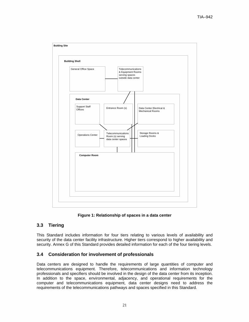
3.2 Relationship of data center spaces to other building spaces
Figure 1 illustrates the major spaces of a typical data center and how they relate to each other and the spaces outside of the data center. See clause 5 for information concerning the telecommunications spaces within the data center.
This Standard addresses telecommunications infrastructure for the data center spaces, which is the computer room and its associated support spaces.
Telecommunications cabling and spaces outside of the computer room and its associated support spaces are illustrated in figure 1 to demonstrate their relationships to the data center.
TIA–942
21
Bulding Site
Data Center
Data Center Electrical &Mechanical Rooms
Support StaffOffices
Operations Center TelecommunicationsRoom (s) servingdata center spaces
Storage Rooms &Loading Docks
Building Shell
General Office Space
Entrance Room (s)
Telecommunications& Equipment Roomsserving spacesoutside data center
Computer Room
Figure 1: Relationship of spaces in a data center
3.3 Tiering
This Standard includes information for four tiers relating to various levels of availability and security of the data center facility infrastructure. Higher tiers correspond to higher availability and security. Annex G of this Standard provides detailed information for each of the four tiering levels.
3.4 Consideration for involvement of professionals
Data centers are designed to handle the requirements of large quantities of computer and telecommunications equipment. Therefore, telecommunications and information technology professionals and specifiers should be involved in the design of the data center from its inception. In addition to the space, environmental, adjacency, and operational requirements for the computer and telecommunications equipment, data center designs need to address the requirements of the telecommunications pathways and spaces specified in this Standard.

TIA-942
22
4 DATA CENTER CABLING SYSTEM INFRASTRUCTURE
4.1 The basic elements of the data center cabling system structure
Figure 2 illustrates a representative model for the various functional elements that comprise a cabling system for a data center. It depicts the relationship between the elements and how they are configured to create the total system.
The basic elements of the data center cabling system structure are the following:
a) Horizontal cabling (subclause 6.2)
b) Backbone cabling (subclause 6.3)
c) Cross-connect in the entrance room or main distribution area
d) Main cross-connect (MC) in the main distribution area
e) Horizontal cross-connect (HC) in the telecommunications room, horizontal distribution area or main distribution area.
f) Zone outlet or consolidation point in the zone distribution area
g) Outlet in the equipment distribution area
MC
Primary Entrance Room
Accessproviders
HC HC HC
Active Equipinterconnect
Active Equipinterconnect Active Equip
interconnect
Active EquipStorage AreaDevices
interconnect
ZoneDistributionArea
Secondary Entrance Room
Offices, OperationsCenter, Support Rooms
Data Center
Backbone cabling
Backbone cabling
Backbone cabling
Hor
izon
tal c
ablin
g
Hor
izon
tal c
ablin
g
Hor
izon
tal c
ablin
g
Hor
izon
tal
cabl
ing
Hor
izon
tal
cabl
ing
Backbone cabling
Backbone cabling
Horizontal cabling
HorizontalDistributionArea
EquipmentDistributionArea
MainDistributionArea
Telecom Room
HC
Accessproviders
Accessproviders
Figure 2: Data center topology

TIA–942
23
5 DATA CENTER TELECOMMUNICATIONS SPACES AND RELATED TOPOLOGIES
5.1 General
The data center requires spaces dedicated to supporting the telecommunications infrastructure. Telecommunications spaces shall be dedicated to support telecommunications cabling and equipment. Typical spaces found within a data center generally include the entrance room, main distribution area (MDA), horizontal distribution area (HDA), zone distribution area (ZDA) and equipment distribution area (EDA). Depending upon the size of the data center, not all of these spaces may be used within the structure. These spaces should be planned to provide for growth and transition to evolving technologies. These spaces may or may not be walled off or otherwise separated from the other computer room spaces.
5.2 Data center structure
5.2.1 Major elements
The data center telecommunications spaces include the entrance room, main distribution area (MDA), horizontal distribution area (HDA), zone distribution area (ZDA) and equipment distribution area (EDA).
The entrance room is the space used for the interface between data center structured cabling system and inter-building cabling, both access provider and customer-owned. This space includes the access provider demarcation hardware and access provider equipment. The entrance room may be located outside the computer room if the data center is in a building that includes general purpose offices or other types of spaces outside the data center. The entrance room may also be outside the computer room for improved security, as it avoids the need for access provider technicians to enter the computer room. Data centers may have multiple entrance rooms to provide additional redundancy or to avoid exceeding maximum cable lengths for access provider-provisioned circuits. The entrance room interfaces with the computer room through the main distribution area. The entrance room may be adjacent to or combined with the main distribution area.
The main distribution area includes the main cross-connect (MC), which is the central point of distribution for the data center structured cabling system and may include horizontal cross-connect (HC) when equipment areas are served directly from the main distribution area. This space is inside the computer room; it may be located in a dedicated room in a multi-tenant data center for security. Every data center shall have at least one main distribution area. The computer room core routers, core LAN switches, core SAN switches, and PBX are often located in the main distribution area, because this space is the hub of the cabling infrastructure for the data center. Access provider provisioning equipment (for example the M13 multiplexers) is often located in the main distribution area rather than in the entrance room to avoid the need for a second entrance room due to circuit length restrictions.
The main distribution area may serve one or more horizontal distribution areas or equipment distribution areas within the data center and one or more telecommunications rooms located outside the computer room space to support office spaces, operations center and other external support rooms.
The horizontal distribution area is used to serve equipment areas when the HC is not located in the main distribution area. Therefore, when used, the horizontal distribution area may include the HC, which is the distribution point for cabling to the equipment distribution areas. The horizontal distribution area is inside the computer room, but may be located in a dedicated room within the

TIA-942
24
computer room for additional security. The horizontal distribution area typically includes LAN switches, SAN switches, and Keyboard/Video/Mouse (KVM) switches for the end equipment located in the equipment distribution areas. A data center may have computer room spaces located on multiple floors with each floor being serviced by its own HC. A small data center may require no horizontal distribution areas, as the entire computer room may be able to be supported from the main distribution area. However, A typical data center will have several horizontal distribution areas.
The equipment distribution area (EDA) is the space allocated for end equipment, including computer systems and telecommunications equipment. These areas shall not serve the purposes of an entrance room, main distribution area or horizontal distribution area.
There may be an optional interconnection point within the horizontal cabling, called a zone distribution area. This area is located between the horizontal distribution area and the equipment distribution area to allow frequent reconfiguration and flexibility.
5.2.2 Typical data center topology
The typical data center includes a single entrance room, possibly one or more telecommunications rooms, one main distribution area, and several horizontal distribution areas. Figure 3 illustrates the typical data center topology.
Entrance Room(Carrier Equip &
Demarcation)
Access Providers
Horiz Dist Area(LAN/SAN/KVM
Switches )
Equip Dist Area(Rack/Cabinet)
ComputerRoom
Horiz Dist Area(LAN/SAN/KVM
Switches )Zone Dist Area
Offices,Operations Center,
Support Rooms
Telecom Room(Office & Operations
Center LAN switches)
Main Dist Area(Routers, BackboneLAN/SAN Switches,PBX, M13 Muxes)
Horiz Dist Area(LAN/SAN/KVM
Switches )
Equip Dist Area(Rack/Cabinet)
Equip Dist Area(Rack/Cabinet)
Backbone cabling
Horizontal cabling Horizontal cabling Horizontal cabling
Horizontal cabling
Backbone cabling
Backbonecabling
Horizontal cabling
Access Providers
Horiz Dist Area(LAN/SAN/KVM
Switches )
Equip Dist Area(Rack/Cabinet)
Horizontal cabling
Figure 3: Example of a basic data center topology
5.2.3 Reduced data center topologies
Data center designers can consolidate the main cross-connect, and horizontal cross-connect in a single main distribution area, possibly as small as a single cabinet or rack. The telecommunications room for cabling to the support areas and the entrance room may also be consolidated into the main distribution area in a reduced data center topology. The reduced data center topology for a small data center is illustrated in Figure 4.

TIA–942
25
Access Providers
Equip DistArea
(Rack/Cabinet)
ComputerRoom
Zone DistArea
Offices,Operations Center,
Support Rooms
Equip DistArea
(Rack/Cabinet)
Main Dist Area(Carrier Equip, Demarcation,Routers, Backbone LAN/SAN/
KVM Switches, PBX, M13Muxes)
Hor
izon
tal c
ablin
g
Horizo
ntal c
ablin
g
Horizontal cabling
Horizontalcabling
Figure 4: Example of a reduced data center topology
5.2.4 Distributed data center topologies
Multiple telecommunications rooms may be required for data centers with large or widely separated office and support areas.
Circuit distance restrictions may require multiple entrance rooms for very large data centers. Additional entrance rooms may be connected to the main distribution area and horizontal distribution areas that they support using twisted-pair cables, optical fiber cables and coaxial cables. The data center topology with multiple entrance rooms is shown in figure 5. The primary entrance room shall not have direct connections to horizontal distribution areas. Secondary entrance rooms are permitted to have direct cabling to horizontal distribution areas if the secondary entrance rooms were added to avoid exceeding maximum circuit length restrictions. Although cabling from the secondary entrance room directly to the HDAs is not common practice or encouraged, it is allowed to meet certain circuit length limitations and redundancy needs.

TIA-942
26
Primary EntranceRoom
(Carrier Equip &Demarcation)
Horiz Dist Area(LAN/SAN/KVM
Switches )
Equip Dist Area(Rack/Cabinet)
Computer Room
Horiz Dist Area(LAN/SAN/KVM
Switches )
Horiz Dist Area(LAN/SAN/KVM
Switches )Zone Dist Area
Offices,Operations Center,
Support Rooms
Telecom Room(Office & Operations
Center LAN switches)
Access Providers
SecondaryEntrance Room
(Carrier Equip &Demarcation)
Main Dist Area(Routers, BackboneLAN/SAN Switches,PBX, M13 Muxes)
Horiz Dist Area(LAN/SAN/KVM
Switches )
Equip Dist Area(Rack/Cabinet)
Equip Dist Area(Rack/Cabinet)
Equip Dist Area(Rack/Cabinet)
Backbone cablingBa
ckbo
ne ca
bling
Backbone cabling
Backbonecabling
Backb
one
cabli
ng
Back
bone
cab
ling
Backbonecabling
Backbonecabling
Bac
kbon
eca
blin
g
Horizontal cablingHorizontal cablingHorizontal cabling
Horizontalcabling
Horizontal cabling
Horizontal cabling
Access Providers
Access Providers
Figure 5: Example of a distributed data center topology with multiple entrance rooms.
5.3 Computer room requirements
5.3.1 General
The computer room is an environmentally controlled space that serves the sole purpose of housing equipment and cabling directly related to the computer systems and other telecommunications systems. The computer room should meet the NFPA 75 standard.
The floor layout should be consistent with equipment and facility providers’ requirements, such as:
- floor loading requirements including equipment, cables, patch cords, and media (static concentrated load, static uniform floor load, dynamic rolling load);
- service clearance requirements (clearance requirements on each side of the equipment required for adequate servicing of the equipment);
- air flow requirements;
- mounting requirements;
- DC power requirements and circuit length restrictions;

TIA–942
27
- equipment connectivity length requirements (for example, maximum channel lengths to peripherals and consoles).
5.3.2 Location
When selecting the computer room site, avoid locations that are restricted by building components that limit expansion such as elevators, core, outside walls, or other fixed building walls. Accessibility for the delivery of large equipment to the equipment room should be provided (see ANSI/TIA-569-B annex B.3).
The room shall be located away from sources of electromagnetic interference. Examples of such noise sources include electrical power supply transformers, motors and generators, x-ray equipment, radio or radar transmitters, and induction sealing devices.
The computer room should not have exterior windows, as exterior windows increase heat load and reduce security.
5.3.3 Access
Computer room doors should provide access to authorized personnel only. Additionally, access to the room shall comply with the requirements of the AHJ. For additional information on monitoring computer room access, see annex G.
5.3.4 Architectural design
5.3.4.1 Size
The computer room shall be sized to meet the known requirements of specific equipment including proper clearances; this information can be obtained from the equipment provider(s). Sizing should include projected future as well as present requirements. See annex E regarding guidelines on sizing of computer rooms.
5.3.4.2 Guidelines for other equipment
Electrical control equipment, such as power distribution or conditioner systems, and UPS up to 100 kVA shall be permitted in the computer room, with the exception of flooded-cell batteries. UPS larger than 100 kVA and any UPS containing flooded-cell batteries should be located in a separate room except as required by the AHJ.
Equipment not related to the support of the computer room (e.g., piping, ductwork, pneumatic tubing, etc.) shall not be installed in, pass through, or enter the computer room.
5.3.4.3 Ceiling height
The minimum height in the computer room shall be 2.6 m (8.5 ft) from the finished floor to any obstruction such as sprinklers, lighting fixtures, or cameras. Cooling requirements or racks/cabinets taller than 2.13 m (7 ft) may dictate higher ceiling heights. A minimum of 460 mm (18 in) clearance shall be maintained from water sprinkler heads.
5.3.4.4 Treatment
Floors, walls, and ceiling shall be sealed, painted, or constructed of a material to minimize dust. Finishes should be light in color to enhance room lighting. Floors shall have anti-static properties in accordance with IEC 61000-4-2.

TIA-942
28
5.3.4.5 Lighting
Lighting shall be a minimum of 500 lux (50 footcandles) in the horizontal plane and 200 lux (20 footcandles) in the vertical plane, measured 1 m (3 ft) above the finished floor in the middle of all aisles between cabinets.
Lighting fixtures should not be powered from the same electrical distribution panel as the telecommunications equipment in the computer room. Dimmer switches should not be used. Emergency lighting and signs shall be properly placed per authority having jurisdiction (AHJ) such that an absence of primary lighting will not hamper emergency exit.
5.3.4.6 Doors
Doors shall be a minimum of 1 m (3 ft) wide and 2.13 m (7 ft) high, without doorsills, hinged to open outward (code permitting) or slide side-to-side, or be removable. Doors shall be fitted with locks and have either no center posts or removable center posts to facilitate access for large equipment. Exit requirements for the computer room shall meet the requirements of the AHJ.
5.3.4.7 Floor loading
Floor loading capacity in the computer room shall be sufficient to bear both the distributed and concentrated load of the installed equipment with associated cabling and media. The minimum distributed floor loading capacity shall be 7.2 kPA (150 lbf/ ft2). The recommended distributed floor loading capacity is 12 kPA (250 lbf/ ft2).
The floor shall also have a minimum of 1.2 kPA (25 lbf/ ft2) hanging capacity for supporting loads that are suspended from the bottom of the floor (for example, cable ladders suspended from the ceiling of the floor below). The recommended hanging capacity of the floor is 2.4 kPA (50 lbf/ ft2). Refer to Telcordia specification GR-63-CORE regarding floor loading capacity measurement and test methods.
5.3.4.8 Signage
Signage, if used, should be developed within the security plan of the building. Proper exit signage shall be placed in accordance with the AHJ.
5.3.4.9 Seismic considerations
Specifications for related facilities shall accommodate the applicable seismic zone requirements. Refer to Telcordia specification GR-63-CORE for more information regarding seismic considerations.
5.3.5 Environmental design
5.3.5.1 Contaminants
The room shall be protected from contaminants in accordance with ANSI/TIA-569-B.

TIA–942
29
5.3.5.2 HVAC
If the computer room does not have a dedicated HVAC system, the computer room shall be located with ready access to the main HVAC delivery system. A computer room is typically not recognized as such by the AHJ unless it has a dedicated HVAC, or utilizes the main building HVAC and has automatic dampers installed.
5.3.5.2.1 Continuous operation
HVAC shall be provided on a 24 hours-per-day, 365 days-per-year basis. If the building system cannot assure continuous operation for large equipment applications, a stand-alone unit shall be provided for the computer room.
5.3.5.2.2 Standby operation
The computer room HVAC system should be supported by the computer room standby generator system, if one is installed. If the computer room does not have a dedicated standby generator system, the computer room HVAC should be connected to the building standby generator system, if one is installed.
5.3.5.3 Operational parameters
The temperature and humidity shall be controlled to provide continuous operating ranges for temperature and humidity:
- dry Bulb Temperature: 20o C (68o F) to 25o C (77o F);
- relative Humidity: 40% to 55%;
- maximum Dew Point: 21o C (69.8o F);
- maximum Rate of Change: 5o C (9o F) per hour;
- humidification and dehumidification equipment may be required depending upon local environmental conditions.
The ambient temperature and humidity shall be measured after the equipment is in operation. Measurements shall be done at a distance of 1.5 m (5 ft) above the floor level every 3 to 6 m (10 to 30 ft) along the center line of the cold aisles and at any location at the air intake of operating equipment. Temperature measurements should be taken at several locations of the air intake of any equipment with potential cooling problems. Refer to ASHRAE for more detailed guidelines for measuring and evaluating computer room temperatures.
A positive pressure differential with respect to surrounding areas should be provided.
5.3.5.4 Batteries
If batteries are used for backup, adequate ventilation and spill containment as required shall be provided. Refer to applicable electrical codes for requirements.
5.3.5.5 Vibration
Mechanical vibration coupled to equipment or the cabling infrastructure can lead to service failures over time. A common example of this type of failure would be loosened connections. Potential vibration problems should be considered in the design of the computer room, since

TIA-942
30
vibration within the building will exist and will be conveyed to the computer room via the building structure. In these cases, the project structural engineer should be consulted to design safeguards against excessive computer room vibration. Refer to Telcordia specification GR-63-CORE for more information regarding vibration testing.
5.3.6 Electrical design
5.3.6.1 Power
Separate supply circuits serving the computer room shall be provided and terminated in their own electrical panel or panels.
The computer room shall have duplex convenience outlets (120V 20A) for power tools, cleaning equipment, and equipment not suitable to plug into equipment cabinet power strips. The convenience outlets should not be on the same power distribution units (PDUs) or electrical panels as the electrical circuits used for the telecommunications and computer equipment in the room. The convenience outlets shall be spaced 3.65 m (12 ft) apart along the computer room walls, or closer if specified by local ordinances, and reachable by a 4.5m (15 ft) cord (per NEC Articles 210.7(A) and 645.5(B1)).
5.3.6.2 Standby power
The computer room electrical panels should be supported by the computer room standby generator system, if one is installed. Any generators used should be rated for electronic loads. Generators of this capability are often referred to as “Computer Grade”. If the computer room does not have a dedicated standby generator system, the computer room electrical panels should be connected to the building standby generator system, if one is installed. The power shutdown requirements for computer room equipment are mandated by the AHJ and vary by jurisdiction.
5.3.6.3 Bonding and grounding (earthing)
Access shall be made available to the telecommunications grounding system specified by ANSI/TIA/EIA-J-STD-607-A. The computer room should have a common bonding network (CBN) (see subclause G.5.1.6).
5.3.7 Fire protection The fire protection systems and hand-held fire extinguishers shall comply with NFPA-75. Sprinkler systems in computer rooms should be pre-action systems.
5.3.8 Water infiltration
Where risk of water ingress exists, a means of evacuating water from the space shall be provided (e.g. a floor drain). Additionally, at least one drain or other means for evacuating water for each 100 m2 (1000 ft2) area should be provided. Any water and drain pipes that run through the room should be located away from and not directly above equipment in the room.
5.4 Entrance room requirements
5.4.1 General
The entrance room is a space, preferably a room, in which access provider-owned facilities interface with the data center cabling system. It typically houses telecommunications access provider equipment and is the location where access providers typically hand off circuits to the customer. This hand-off point is called the demarcation point. It is where the telecommunications
TIA–942
31
access provider’s responsibility for the circuit typically ends and the customer’s responsibility for the circuit begins.
The entrance room will house entrance pathways, protector blocks for copper-pair entrance cables, termination equipment for access provider cables, access provider equipment, and termination equipment for cabling to the computer room.
5.4.2 Location
The entrance room should be located to ensure that maximum circuit lengths from the access provider demarcation points to the end equipment are not exceeded. The maximum circuit lengths need to include the entire cable route, including patch cords and changes in height between floors and within racks or cabinets. Specific circuit lengths (from demarcation point to end equipment) to consider when planning entrance room locations are provided in annex A.
NOTE: Repeaters can be used to extend circuits beyond the lengths specified in annex A.
The entrance rooms may either be located inside or outside the computer room space. Security concerns may dictate that the entrance rooms are located outside the computer room to avoid the need for access provider technicians to access the computer room. However, in larger data centers, circuit length concerns may require that the entrance room be located in the computer room.
Cabling in the entrance rooms should use the same cable distribution (overhead or under floor) as used in the computer room; this will minimize cable lengths as it avoids a transition from overhead cable trays to under floor cable trays.
5.4.3 Quantity
Large data centers may require multiple entrance rooms to support some circuit types throughout the computer room space and/or to provide additional redundancy.
The additional entrance rooms may have their own entrance pathways for dedicated service feeds from the access providers. Alternatively, the additional entrance rooms may be subsidiaries of the primary entrance room, in which case the access provider service feeds come from the primary entrance room.
5.4.4 Access
Access to the entrance room shall be controlled by the data center owner or their agent.
5.4.5 Entrance conduit routing under access floor
If the entrance room is located in the computer room space, the entrance conduit runs should be designed to avoid interfering with airflow, chilled water piping and other cable routing under the access floor.
5.4.6 Access provider and service provider spaces
Access provider and service provider spaces for data centers are typically located either in the entrance room or in the computer room. Refer to ANSI/TIA-569-B for information on access provider and service provider spaces.

TIA-942
32
The access provider and service provider spaces in data center entrance rooms typically do not require partitions because access to the data center entrance rooms is carefully controlled. Access and service providers that lease space in the computer room, however, typically require secure access to their spaces.
5.4.7 Building entrance terminal
5.4.7.1 General
Listed herein are the requirements for building entrance terminals located at the cabling entrance to building facilities where the transition between inside and outside environments occur. Outside terminals are typically used when the entrance connection is located in a closure on an outside wall of a building. Inside terminals are used when the outside cable will be connected to the inside distribution cabling system. Refer to ANSI/TIA/EIA-568-B.1 for additional information on entrance facilities and entrance facility connections.
5.4.8 Architectural design
5.4.8.1 General
The decision whether a room or open area is provided should be based on security (with consideration to both access and incidental contact), the need for wall space for protectors, entrance room size, and physical location.
5.4.8.2 Size
The entrance room shall be sized to meet known and projected maximum requirements for:
- entrance pathways for access provider and campus cabling;
- backboard and frame space for termination of access provider and campus cabling;
- access provider racks;
- customer-owned equipment to be located in the entrance room;
- demarcation racks including termination hardware for cabling to the computer room;
- pathways to the computer room, the main distribution area and possibly horizontal distribution area for secondary entrance rooms;
- pathways to other entrance rooms if there are multiple entrance rooms.
The space required is related more closely to the number of access providers, number of circuits, and type of circuits to be terminated in the room than to the size of the data center. Meet with all access providers to determine their initial and future space requirements. See annex C for more information regarding access provider coordination and access provider demarcation.
Space should also be provided for campus cabling. Cables containing metallic components (copper-pair, coaxial, optical fiber cables with metallic components etc.) shall be terminated with protectors in the entrance room. The protectors may either be wall-mounted or frame-mounted. The space for protectors shall be located as close as practical to the point of entrance of the cables into the building. Optical fiber campus cables may be terminated in the main cross-connect instead of the entrance room if they have no metallic components (for example, cable

TIA–942
33
sheath or strength member). Refer to applicable codes regarding entrance cable and entrance cable termination requirements.
5.4.8.3 Plywood backboards
Where wall terminations are to be provided for protectors, the wall should be covered with rigidly fixed 20 mm (¾ in) A-C plywood, preferably void free, 2.4 m (8 ft) high, and capable of supporting attached connecting hardware. Plywood should be either fire-rated (fire-retardant) or covered with two coats of fire retardant paint.
If fire-rated (fire-retardant) plywood is to be painted, the paint should not cover the fire-rating stamp until inspection by the fire marshal or other AHJ is complete. To reduce warping, fire-rated (fire-retardant) plywood shall be kiln-dried and shall not exceed moisture content of 15 %.
5.4.8.4 Ceiling height
The minimum height shall be 2.6 m (8.5 ft) from the finished floor to any obstruction such as sprinklers, lighting fixtures, or cameras. Cooling requirements or racks/cabinets taller than 2.13 m (7 ft) may dictate higher ceiling heights. A minimum of 460 mm (18 in) clearance shall be maintained from water sprinkler heads.
5.4.8.5 Treatment
Floors, walls, and ceiling shall be sealed, painted, or constructed of a material to minimize dust. Finishes should be light in color to enhance room lighting. Floors shall have anti-static properties as per IEC 61000-4-2.
5.4.8.6 Lighting
Lighting shall be a minimum of 500 lux (50 footcandles) in the horizontal plane and 200 lux (20 footcandles) in the vertical plane, measured 1 m (3 ft) above the finished floor in middle of all aisles between cabinets.
Lighting fixtures should not be powered from the same electrical distribution panel as the telecommunications equipment in the computer room. Dimmer switches should not be used. Emergency lighting and signs shall be properly placed per AHJ such that an absence of primary lighting will not hamper emergency exit.
5.4.8.7 Doors
Doors shall be a minimum of 1 m (3 ft) wide and 2.13 m (7 ft) high, without doorsill, hinged to open outward (code permitting) or slide side-to-side, or be removable. Doors shall be fitted with a lock and have either no center post or a removable center post to facilitate access for large equipment.
5.4.8.8 Signage
Signage, if used, should be developed within the security plan of the building.
5.4.8.9 Seismic considerations
Specifications for related facilities shall accommodate the applicable seismic zone requirements. Refer to Telcordia specification GR-63-CORE for more information regarding seismic considerations.

TIA-942
34
5.4.8.10 HVAC
The entrance room shall be located with ready access to the computer room HVAC delivery system. Consider having dedicated air-conditioning for the entrance room. If the entrance room has dedicated air-conditioning, temperature control circuits for the entrance room air-conditioning units should be powered from the same PDUs or panel boards that serve the entrance room racks.
HVAC for the equipment in the entrance room should have the same degree of redundancy and backup as the HVAC and power for the computer room.
5.4.8.10.1 Continuous operation
HVAC shall be provided on a 24 hours-per-day, 365 days-per-year basis. If the building system cannot assure continuous operation, a stand-alone unit shall be provided for the data center entrance room.
5.4.8.10.2 Standby operation
The entrance room HVAC system should be supported by the computer room standby generator system, if one is installed. If the computer room or entrance room does not have a dedicated standby generator system, the entrance room HVAC should be connected to the building standby generator system, if one is installed.
5.4.8.11 Operational parameters
The temperature and humidity shall be controlled to provide continuous operating ranges for temperature and humidity:
- dry Bulb Temperature: 20o C (68o F) to 25o C (77o F);
- relative Humidity: 40% to 55%;
- maximum Dew Point: 21o C (69.8o F);
- maximum Rate of Change: 5o C (9o F) per hour;
- humidification and dehumidification equipment may be required depending upon local environmental conditions.
The ambient temperature and humidity shall be measured after the equipment is in operation. Measurement shall be done at a distance of 1.5 m (5 ft) above the floor level every 3 to 6 m (10 to 30 ft) along the center line of the cold aisles and at any location at the air intake of operating equipment. Temperature measurements should be taken at several locations of the air intake of any equipment with potential cooling problems.
5.4.8.12 Power
Consider having dedicated PDUs and UPS fed power panels for the entrance room. The quantity of electrical circuits for entrance rooms depends on the requirements of the equipment to be located in the room. The entrance rooms shall use the same electrical backup systems (UPS and generators) as that used for the computer room. The degree of redundancy for entrance room mechanical and electrical systems shall be the same as that for the computer room.

TIA–942
35
The entrance room shall have one or more duplex convenience outlets (120V 20A) for power tools, cleaning equipment, and other equipment not suitable to plug into equipment rack power strips. The convenience outlets should not be on the same PDU or electrical panel as the electrical circuits used for the telecommunications and computer equipment in the room. There shall be at least one duplex outlet on each wall of the room, spaced no more than 4m (12 ft) apart, and in floor boxes, poke through and other delivery systems such that they can be reached by a 4.5 m (15 ft) power cord from any place in the room as per the NFPA 70 article 645.5 (B1) or as per the AHJ.
5.4.8.13 Standby Power
The entrance room electrical panels should be supported by the computer room standby generator system, if one is installed. Any generators used should be rated for electronic loads. Generators of this capability are often referred to as “Computer Grade”. If the computer room or entrance room does not have a dedicated standby generator system, the entrance room electrical panels should be connected to the building standby generator system, if one is installed.
5.4.8.14 Bonding and grounding
Access shall be made available to the telecommunications grounding system specified by ANSI/TIA/EIA-J-STD-607-A.
5.4.9 Fire protection The fire protection systems and hand-held fire extinguishers shall comply with NFPA-75. Sprinkler systems in computer rooms should be pre-action systems.
5.4.10 Water infiltration
Where risk of water ingress exists, a means of evacuating water from the space shall be provided (e.g. a floor drain). Any water and drain pipes that run through the room should be located away from and not directly above equipment in the room.
5.5 Main distribution area
5.5.1 General
The main distribution area (MDA) is the central space where the point of distribution for the structured cabling system in the data center is located. The data center shall have at least one main distribution area. The core routers and core switches for the data center networks are often located in or near the main distribution area.
In data centers that are used by multiple organizations, such as Internet data centers and collocation facilities, the main distribution area should be in a secure space.
5.5.2 Location
The main distribution area should be centrally located to avoid exceeding maximum distance restrictions for the applications to be supported, including maximum cable lengths for access provider circuits served out of the entrance room.
5.5.3 Facility requirements
If the main distribution area is in an enclosed room, consider a dedicated HVAC, PDU, and UPS fed power panels for this area.

TIA-942
36
If the main distribution area has dedicated HVAC, the temperature control circuits for air-conditioning units should be powered and controlled from the same PDUs or power panels that serve the telecommunications equipment in the main distribution area.
The architectural, mechanical, and electrical requirements for the main distribution area are the same as that for the computer room.
5.6 Horizontal distribution area
5.6.1 General
The horizontal distribution area (HDA) is the space that supports cabling to the equipment distribution areas. The LAN, SAN, console, and KVM switches that support the end equipment are also typically located in the horizontal distribution area. The main distribution area may serve as a horizontal distribution area for nearby equipment or for the entire computer room if the computer room is small.
There should be a minimum of one horizontal distribution area per floor. Additional horizontal distribution areas may be required to support equipment beyond the horizontal cable length limitation.
The maximum number of connections per horizontal distribution area should be adjusted based on cable tray capacity, leaving room in the cable trays for future cabling.
In data centers that are used by multiple organizations, such as Internet data centers and collocation facilities, the horizontal distribution areas should be in a secure space.
5.6.2 Location
The horizontal distribution areas should be located to avoid exceeding maximum backbone lengths from the MDA and maximum distances for the media type.
5.6.3 Facility requirements
If the horizontal distribution area is in an enclosed room, consideration regarding a dedicated HVAC, PDUs, and UPS fed power panels for the horizontal distribution area should be taken.
The temperature control circuits and air-conditioning units should be powered from a different PDUs or power panels that serve the telecommunications equipment in the horizontal distribution area.
The architectural, mechanical, and electrical requirements for the horizontal distribution area are the same as that for the computer room.
5.7 Zone distribution area
The zone distribution area should be limited to serving a maximum of 288 coaxial or twisted-pair connections to avoid cable congestion, particularly for enclosures meant to be placed overhead or under 2 ft. x 2 ft. (or 600 mm x 600 mm) access floor tiles.
Cross-connection shall not be used in the zone distribution area. No more than one zone distribution area shall be used within the same horizontal cable run.
There shall be no active equipment in the zone distribution area with the exception of DC powering equipment.

TIA–942
37
5.8 Equipment distribution areas
The equipment distribution areas are spaces allocated for end equipment, including computer systems and communications equipment. These areas do not include the telecommunications rooms, entrance rooms, main distribution area, and horizontal distribution areas.
The end equipment is typically floor standing equipment or equipment mounted in cabinets or racks.
Horizontal cables are terminated in equipment distribution areas on connecting hardware mounted in the cabinets or racks. Sufficient power receptacles and connecting hardware should be provided for each equipment cabinet and rack to minimize patch cord and power cord lengths.
Point-to-point cabling is permitted between equipment located in the equipment distribution area. Cable lengths for point-to-point cabling between equipment in the equipment distribution area should be no greater than 15 m (49 ft) and should be between equipment in adjacent racks or cabinets in the same row.
5.9 Telecommunications room
In data centers, the telecommunications room (TR) is a space that supports cabling to areas outside the computer room. The TR is normally located outside the computer room but, if necessary, it can be combined with the main distribution area or horizontal distribution areas.
The data center may support more than one telecommunications room if the areas to be served cannot be supported from a single telecommunications room.
The telecommunication rooms shall meet the specifications of ANSI/TIA-569-B.
5.10 Data center support areas
The data center support areas are spaces outside the computer room that are dedicated to supporting the data center facility. These may include the operation center, support personnel offices, security rooms, electrical rooms, mechanical rooms, storage rooms, equipment staging rooms, and loading docks.
The operation center, security room, and support personnel offices shall be cabled similarly to standard office areas, as per ANSI/TIA/EIA-568-B.1. The operation center consoles and security consoles will require larger numbers of cables than standard work area requirements. The quantity should be determined with the assistance of the operations and technical staff. The operation center may also require cabling for large wall-mounted or ceiling-mounted displays (e.g., monitors and televisions).
The electrical rooms, mechanical rooms, storage rooms, equipment staging rooms, and loading docks should have at least one wall phone each. The electrical and mechanical rooms should also have at least one data connection for access to the facility management system.
5.11 Racks and cabinets
5.11.1 General
Racks are equipped with side mounting rails to which equipment and hardware are mounted. Cabinets can be equipped with side mounting rails, side panels, a top, and front and rear doors, and are frequently equipped with locks.

TIA-942
38
5.11.2 "Hot" and "cold" aisles
Cabinets and racks shall be arranged in an alternating pattern, with fronts of cabinets/racks facing each other in a row to create "hot" and "cold" aisles.
"Cold" aisles are in front of racks and cabinets. If there is an access floor, power distribution cables should be installed here under the access floor on the slab.
"Hot" aisles are behind racks and cabinets. If there is an access floor, cable trays for telecommunications cabling should be located under the access floor in the “hot” aisles.
Front
Rear
Cabinets
“COLD” AISLE(Front of Cabinets)
Front
Front
Rear
Rear
Cabinets
Cabinets
Align Front or Rear of Cabinetswith Edge of Floor Tiles
This Row of Tiles Can Be Lifted
This Row of Tiles Can Be Lifted
Align Front or Rear of Cabinetswith Edge of Floor Tiles
“HOT” AISLE (Rear ofCabinets)This Row of Tiles Can Be Lifted
Figure 6: Example of "hot" aisles, "cold" aisles and cabinet placement
5.11.3 Equipment placement
Equipment should be placed in cabinets and racks with “cold” air intake at the front of the cabinet or rack, and “hot” air exhaust out the back. Reversing equipment in the rack will disrupt the proper functioning of “hot” and “cold” aisles. Equipment that uses the front-to-rear cooling scheme should be used so that it does not disrupt the functioning of hot and cold aisles.
Blank panels should be installed in unused rack and cabinet spaces to improve the functioning of "hot" and "cold" aisles. Perforated access floor tiles should be located in the “cold” aisles rather than in the “hot” aisles to improve the functioning of the “hot” and “cold” aisles. Additionally, no cable trays or other obstruction should be placed in the “cold” aisles below the perforated tiles.
See annex D for additional information regarding coordination of equipment plans with other disciplines.

TIA–942
39
5.11.4 Placement relative to floor tile grid When placed on access floor, cabinets and racks shall be arranged so that they permit tiles in the front and rear of the cabinets and racks to be lifted. Cabinets should be aligned with either the front or rear edge along the edge of the floor tile. Racks should be placed such that the threaded rods that secure the racks to the slab will not penetrate an access floor stringer.
5.11.5 Access floor tile cuts
Floor tile cuts should be no larger than necessary. Dampers or brushes should be installed on floor tile cuts to minimize air loss through openings in the floor tiles. Floor tile cuts shall have edging or grommets along all cut edges.
Floor tile cuts for cabinets should be placed under the cabinets or other location where the floor tile cut will not create a tripping hazard.
Floor tile cuts for racks should be placed either under the vertical cable managers between the racks or under the rack (at the opening between the bottom angles). Generally, placing the floor tile cut under the vertical cable managers is preferable as it allows equipment to be located at the bottom of the rack.
Cabinets and racks should be placed at the same location on each floor tile so that floor tile cuts can be standardized. Thus, cabinets should be the same width as the floor tiles and the combined width of one rack and one vertical wire manager should be the same width as the floor tile. Additionally, spacers may be employed between cabinets to ensure that each cabinet in a row starts at the edge of a floor tile. Exceptions to this general rule are:
- main distribution area and horizontal distribution area where large vertical cable managers are typically used to provide adequate cable management;
- entrance room access provider racks and cabinets, which are often 585 mm (23 in) rather than 480 mm (19 in) racks;
- cabinets for large servers that do not fit in standard 480 mm (19 in) cabinets.
5.11.6 Installation of racks on access floors
Seismic racks shall either be bolted to a seismic stand or bolted directly to the slab.
Racks that are supported by the access floor shall be bolted to the cement slab or a metal channel secured to the slab by threaded rods that penetrate through the floor tiles.
Sharp edges on the top of the threaded rods shall be covered using domed nuts or other method. Exposed threads under the access floor should be covered using split tubing or other method.
5.11.7 Specifications
5.11.7.1 Clearances
A minimum of 1 m (3 ft) of front clearance shall be provided for installation of equipment. A front clearance of 1.2 m (4 ft) is preferable to accommodate deeper equipment. A minimum of 0.6 m (2 ft) of rear clearance shall be provided for service access at the rear of racks and cabinets. A rear clearance of 1 m (3 ft) is preferable. Some equipment may require service clearances of greater than 1 m (3 ft). See equipment manufacturer requirements
TIA-942
40
5.11.7.2 Cabinet ventilation
The cabinets shall be selected to provide adequate ventilation for the equipment it will house. Ventilation can be achieved by using:
- forced airflow utilizing fans;
- utilizing natural airflow between hot and cold aisles through ventilation openings in the front and rear doors of the cabinets;
- a combination of both methods.
For moderate heat loads, cabinets can utilize any of the following ventilation practices:
1) Ventilation through slots or perforations of front and rear doors to provide a minimum of 50% open space. Increasing the size and area of ventilation openings can increase the level of ventilation.
2) Ventilation through forced airflow utilizing fans in combination with properly placed door vents, and sufficient space between the equipment and rack doors.
For high heat loads, natural airflow is not sufficient and forced airflow is required to provide adequate cooling for all the equipment in the cabinet. A forced airflow system utilizes a combination of properly placed vents in addition to the cooling fan systems.
If cabinet fans are installed, they should be of the type that is designed to enhance rather than disrupt the functioning of “hot” and “cold” aisles. Airflow from the fans should adequate to dissipate the heat generated in the cabinet.
In data centers where the highest availability is desired, fans should be wired from separate circuits than those fed by the PDUs or UPS fed power panels to avoid disruption to telecommunications and computer equipment when fans fail.
5.11.7.3 Cabinet and rack height
The maximum rack and cabinet height shall be 2.4 m (8 ft). Racks and cabinets should preferably be no taller than 2.1 m (7 ft) for easier access to the equipment or connecting hardware installed at the top.
5.11.7.4 Cabinet depth and width
Cabinets should be of adequate depth to accommodate the planned equipment, including cabling at the front and/or rear, power cords, cable management hardware, and power strips. To ensure adequate airflow and to provide adequate space for power strips and cabling, consider using cabinets that are at least 150 mm (6 in) deeper or wider than the deepest.
5.11.7.5 Adjustable rails
Cabinets should have adjustable front and rear rails. The rails should provide 42 or more rack units (RUs) of mounting space. Rails may optionally have markings at rack unit boundaries to simplify positioning of equipment. Active equipment and connecting hardware should be mounted on the rails on rack unit boundaries to most efficiently utilize cabinet space.
If patch panels are to be installed on the front of cabinets, the front rails should be recessed at least 100 mm (4 in) to provide room for cable management between the patch panels and doors

TIA–942
41
and to provide space for cabling between cabinets. Similarly, if patch panels are to be installed on the rear of cabinets, the rear rails should be recessed at least 100 mm (4 in).
Patch panels shall not be installed on both the front and rear rails of a cabinet or rack in a manner to prevent service access to the rear of the patch panels.
If power strips are to be installed on the front or rear rail of cabinets, adequate clearance should be provided for power cords and power supplies that may be installed on the power strips.
5.11.7.6 Rack and cabinet finishes
Painted finishes should be powder coat or other scratch-resistant finishes.
5.11.7.7 Power strips
Cabinets and racks with no active equipment do not require power strips.
The typical configuration for power strips in cabinets provides at least one 20A, 120V power strip. The use of two power strips which contain circuits that are fed from diverse power sources should be considered. Power circuits should have dedicated neutral and ground conductors. Power strips with indicators but no on/off switch or breaker reset button should be used to minimize accidental shut-off. A number of power strips should be used to provide enough receptacles and current capacity to support the planned equipment. The plug for the power strip should be a locking plug to prevent accidental disconnection.
Power strips shall be labeled with the PDU/panel identifier and circuit breaker number.
5.11.7.8 Additional cabinet and rack specifications
Refer to ANSI T1.336 for additional specifications for cabinets and racks. In addition to the requirements specified in T1.336, cabinets and racks heights up to 2.4 m (8 ft) and cabinet depths up to 1.1 m (43 in) may be used in data centers.
5.11.8 Racks and cabinets in entrance room, main distribution areas and horizontal distribution areas
The entrance room, main distribution area and horizontal distribution areas should use 480 mm (19 in) racks for patch panels and equipment. Service providers may install their own equipment in the entrance room in either 585 mm (23 in) racks or proprietary cabinets.
In the entrance room, main distribution area, and horizontal distribution areas, a vertical cable manager shall be installed between each pair of racks and at both ends of every row of racks. The vertical cable managers shall be not less than 83 mm (3.25 in) in width. Where single racks are installed, the vertical cable managers should be at least 150 mm (6 in) wide. Where a row of two or more racks is installed, consider mounting 250mm (10 in) wide vertical cable managers between racks, and 150 mm (6 in) wide vertical cable managers at both ends of the row. The cable managers should extend from the floor to the top of the racks.
In the entrance room, main distribution area and horizontal distribution areas, horizontal cable management panels should be installed above and below each patch panel. The preferred ratio of horizontal cable management to patch panels is 1:1.
The vertical cable management, horizontal cable management, and slack storage should be adequate to ensure that the cables can be neatly dressed and that bend radius requirements specified in ANSI/EIA/TIA-568-B.2 and ANSI/EIATIA-568-B.3 are met.

TIA-942
42
Overhead cable trays should be for management of patch cables between racks.
Overhead cable tray should not be used for structural support for racks. It is recommended that a structural engineer be consulted in determining appropriate mounting for high weight load applications.

TIA–942
43
6 DATA CENTER CABLING SYSTEMS
6.1 General
The Data Center cabling system is a cabling infrastructure that will support a multi-product, multi-vendor environment.
6.2 Horizontal Cabling
6.2.1 General
The horizontal cabling is the portion of the telecommunications cabling system that extends from the mechanical termination in the equipment distribution area to either the horizontal cross-connect in the horizontal distribution area or the main cross-connect in the main distribution area. The horizontal cabling includes horizontal cables, mechanical terminations, and patch cords or jumpers, and may include a zone outlet or a consolidation point in the zone distribution area.
NOTE: The term "horizontal" is used since typically the cable in this part of the cabling system runs horizontally along the floor(s) or ceiling(s) of the data center.
The following partial listing of common services and systems should be considered when the horizontal cabling is designed:
- voice, modem, and facsimile telecommunications service;
- premises switching equipment;
- computer and telecommunications management connections;
- keyboard/video/mouse (KVM) connections;
- data communications;
- wide area networks (WAN);
- local area networks (LAN);
- storage area networks (SAN);
- other building signaling systems (building automation systems such as fire, security, power, HVAC, EMS, etc.).
In addition to satisfying today’s telecommunication requirements, the horizontal cabling should be planned to reduce ongoing maintenance and relocation. It should also accommodate future equipment and service changes. Consideration should be given to accommodating a diversity of user applications in order to reduce or eliminate the probability of requiring changes to the horizontal cabling as equipment needs evolve. The horizontal cabling can be accessed for reconfiguration under the access floor or overhead on cable tray systems. However, in a properly planned facility, disturbance of the horizontal cabling should only occur during the addition of new cabling.

TIA-942
44
6.2.2 Topology
The horizontal cabling shall be installed in a star topology as shown in figure 7. Each mechanical termination in the equipment distribution area shall be connected to a horizontal cross-connect in the horizontal distribution area or main cross-connect in the main distribution area via a horizontal cable.
Horizontal cabling shall contain no more than one consolidation point in the zone distribution area between the horizontal cross-connect in the horizontal distribution area and the mechanical termination in the equipment distribution area. Refer to subclause 5.7 for additional information regarding zone distribution areas.
Equip DistArea
Zone DistArea
Equip DistArea
HorizontalDistribution Area
Horizontal cable
Horizontal cable
Horizontal cable
Figure 7: Typical horizontal cabling using a star topology
6.2.3 Horizontal cabling distances
The horizontal cabling distance is the cable length from the mechanical termination of the media at the horizontal cross-connect in the horizontal distribution area or the main distribution area to the mechanical termination of the media in the equipment distribution area. The maximum horizontal distance shall be 90 m (295 ft), independent of media type (see figure 7). The maximum channel distance including equipment cords shall be 100 m (328 ft). The maximum cabling distance in a data center not containing a horizontal distribution area shall be 300 m (984 ft) for an optical fiber channel including equipment cords, 90 m (294 ft) for copper cabling excluding equipment cords and 100 m (328 ft) for copper cabling including equipment cords. If a zone outlet is used, the maximum horizontal distances of copper media shall be reduced in accordance with subclause 6.2.3.1.
Additionally, horizontal cable distances in a computer room may need to be reduced to compensate for longer equipment cords in the data center distribution areas. Therefore, careful considerations to the horizontal cable distance should be made to ensure cabling distances and transmission requirements are not exceeded when the equipment cords are attached. Refer to annex A for additional information on application-based cabling distances.
NOTE: For copper cabling, in order to reduce the effect of multiple connections in close proximity on NEXT loss and return loss, the zone distribution area termination should be located at least 15 m (49 ft) from the horizontal distribution area termination.

TIA–942
45
6.2.3.1 Maximum lengths for copper cabling
Copper equipment cables used in the context of zone outlets in the zone distribution area, shall meet the requirements of ANSI/TIA/EIA-568-B.2. Based upon insertion loss considerations, the maximum length shall be determined according to:
C = (102 - H)/(1+D) (1)
Z = C - T ≤ 22 m (72 ft) for 24 AWG UTP/ScTP or ≤ 17 m (56 ft) for 26 AWG ScTP (2)
Where:
C is the maximum combined length (m) of the zone area cable, equipment cable, and patch cord.
H is the length (m) of the horizontal cable (H + C ≤ 100 m).
D is a de-rating factor for the patch cord type (0.2 for 24 AWG UTP/24 AWG ScTP and 0.5 for 26 AWG ScTP).
Z is the maximum length (m) of the zone area cable.
T is the total length of patch and equipment cords.
Table 1 applies the above formulae assuming that there is a total of 5 m (16 ft) of 24 AWG UTP/24AWG ScTP or 4 m (13 ft) of 26 AWG ScTP patch cords and equipment cables in the main distribution area, or horizontal distribution area. The zone outlet shall be marked with the maximum allowable zone area cable length. One method to accomplish this is to evaluate cable length markings.
Table 1: Maximum length of horizontal and equipment area cables
24 AWG UTP/24 AWG ScTP patch cords
26 AWG ScTP patch cords
Length of horizontal cable
Maximum length of zone
area cable
Maximum combined length of zone area cables, patch cords, and equipment cable
Maximum length of
zone area cable
Maximum combined length of zone area cables, patch cords, and equipment cable
H m (ft)
Z m (ft)
C m (ft)
Z m (ft)
C m (ft)
90 (295) 5 (16) 10 (33) 4 (13) 8 (26) 85 (279) 9 (30) 14 (46) 7 (23) 11 (35) 80 (262) 13 (44) 18 (59) 11 (35) 15 (49) 75 (246) 17 (57) 22 (72) 14 (46) 18 (59) 70 (230) 22 (72) 27 (89) 17 (56) 21 (70)
6.2.4 Recognized media
Due to the wide range of services and site sizes where horizontal cabling will be used, more than one transmission medium is recognized. This Standard specifies transmission media, which shall be used individually or in combination in the horizontal cabling.
Recognized cables, associated connecting hardware, jumpers, patch cords, equipment cords, and zone area cords shall meet all applicable requirements specified in ANSI/TIA/EIA-568-B.2 and ANSI/TIA/EIA-568-B.3.

TIA-942
46
The recognized media are:
- 100-ohm twisted-pair cable (ANSI/TIA/EIA-568-B.2), category 6 recommended (ANSI/TIA/EIA-568-B.2-1);
- multimode optical fiber cable, either 62.5/125 micron or 50/125 micron (ANSI/TIA/EIA-568-B.3), 50/125 micron 850 nm laser optimized multimode fiber is recommended (ANSI/TIA-568-B.3-1);
- single-mode optical fiber cable (ANSI/TIA/EIA-568-B.3).
The recognized coaxial media are 75-ohm (734 and 735 type) coaxial cable (Telcordia Technologies GR-139-CORE) and coaxial connector (ANSI T1.404). These cables and connectors are recommended to support specific applications per annex A.
Channels constructed from recognized cables, associated connecting hardware, jumpers, patch cords, equipment cords, and zone area cords shall meet the requirements specified in ANSI/TIA/EIA-568-B.1, ANSI/TIA/EIA-568-B.2, ANSI/TIA/EIA-568-B.3 and ANSI T1.404 (DS3).
NOTES
1) Crosstalk between individual, unshielded twisted-pairs may affect the transmission performance of multipair copper cables. Annex B of ANSI/TIA/EIA-568-B.1 provides some shared sheath guidelines for multipair cables.
2) See subclause 6.2.3 for horizontal cabling distance limitations.
6.3 Backbone cabling
6.3.1 General
The function of the backbone cabling is to provide connections between the main distribution area, the horizontal distribution area, and entrance facilities in the data center cabling system. Backbone cabling consists of the backbone cables, main cross-connects, horizontal cross-connects, mechanical terminations, and patch cord or jumpers used for backbone-to-backbone cross-connection.
The backbone cabling is expected to serve the needs of the data center occupants for one or several planning phases, each phase spanning a time scale that may be on the order of days or months. During each planning period, the backbone cabling design should accommodate growth and changes in service requirements without the installation of additional cabling. The length of the planning period is ultimately dependent on the design logistics including material procurement, transportation, installation and specification control.
The backbone cabling shall allow network reconfiguration and future growth without disturbance of the backbone cabling. The backbone cabling should support different connectivity requirements, including both the network and physical console connectivity such as local area networks, wide area networks, storage area networks, computer channels, and equipment console connections.

TIA–942
47
6.3.2 Topology
6.3.2.1 Star topology
The backbone cabling shall use the hierarchical star topology as illustrated by figure 8 wherein each horizontal cross-connect in the horizontal distribution area is cabled directly to a main cross-connect in the main distribution area. There shall be no more than one hierarchical level of cross-connect in the backbone cabling. From the horizontal cross-connect, no more than one cross-connect shall be passed through to reach another horizontal cross-connect.
HorizontalDistribution
Area
EntranceRoom
Backbone cables
Backbone cables
MainDistribution
AreaHorizontal
DistributionArea
TR
Figure 8: Typical backbone cabling using a star topology
The presence of the horizontal cross-connect is not mandatory. When the horizontal cross-connects are not used, the cabling extending from the main cross-connect to the mechanical termination in the equipment distribution area is considered horizontal cabling. If the horizontal cabling passes through the HDA, sufficient cable slack shall exist in the horizontal distribution area to allow movement of the cables when migrating to a cross-connect.
Backbone cabling cross-connects may be located in telecommunications rooms, equipment rooms, main distribution areas, horizontal distribution areas or at entrance rooms. In the case of multiple entrance rooms, direct backbone cabling to the horizontal cross-connect shall be allowed when distance limitations are encountered.
6.3.2.2 Accommodation of non-star configurations
The topology in figure 8, through the use of appropriate interconnections, electronics, or adapters in data center distribution areas, can often accommodate systems that are designed for non-star configurations such as ring, bus, or tree.
- Cabling between HDAs should be permitted to provide redundancy and to avoid exceeding legacy application distance restrictions.
6.3.3 Redundant cabling topologies
Redundant topologies can include a parallel hierarchy with redundant distribution areas. These topologies are in addition to the star topology specified in subclauses 6.2.2 and 6.3.2. See clause 8 for additional information.

TIA-942
48
6.3.4 Recognized media
Due to the wide range of services and site sizes where backbone cabling will be used, more than one transmission medium is recognized. This Standard specifies transmission media, which shall be used individually or in combination in the backbone cabling.
Recognized cables, associated connecting hardware, jumpers, patch cords, equipment cords, and zone area cords shall meet all applicable requirements specified in ANSI/TIA/EIA-568-B.2 and ANSI/TIA/EIA-568-B.3.
The recognized media are:
- 100-ohm twisted-pair cable (ANSI/TIA/EIA-568-B.2), category 6 recommended (ANSI/TIA/EIA-568-B.2-1);
- multimode optical fiber cable, either 62.5/125 micron or 50/125 micron (ANSI/TIA/EIA-568-B.3), 50/125 micron 850 nm laser optimized multimode fiber is recommended (ANSI/TIA-568-B.3-1);
- single-mode optical fiber cable (ANSI/TIA/EIA-568-B.3).
The recognized coaxial media are 75-ohm (734 and 735 type) coaxial cable (Telcordia Technologies GR-139-CORE) and coaxial connector (ANSI T1.404). These cables and connectors are recommended to support specific applications per annex A.
Channels constructed from recognized cables, associated connecting hardware, jumpers, patch cords, equipment cords, and zone area cords shall meet the requirements specified in ANSI/TIA/EIA-568-B.1, ANSI/TIA/EIA-568-B.2, ANSI/TIA/EIA-568-B.3 and ANSI T1.404 (DS3).
NOTES
1) Crosstalk between individual, unshielded twisted-pairs may affect the transmission performance of multipair copper cables. Annex B of ANSI/TIA/EIA-568-B.1 provides some shared sheath guidelines for multipair cables.
2) Annex C of ANSI/TIA/EIA-568-B.1 provides a brief description of a number of other backbone cables that have been used in telecommunications. These cables, as well as others, may be effective for specific applications. Although these cables are not part of the requirements of this Standard, they may be used in addition to the minimum requirements of this Standard.
3) See subclause 6.3.5 for backbone cabling distance limitations.
6.3.5 Backbone cabling distances
The maximum supportable distances are application and media dependent. The maximum backbone distances in annex A of this document provide application specific guidelines. To minimize cabling distances, it is often advantageous to locate the main cross-connect near the center of a site. Cabling installations that exceed these distance limits may be divided into areas, each of which can be supported by backbone cabling within the scope of this Standard. Interconnections between the individual areas, which are outside the scope of this Standard, may be accomplished by employing equipment and technologies normally used for wide area applications.

TIA–942
49
The length of category 3 multipair balanced 100 Ohm backbone cabling, that supports applications up to 16 MHz, should be limited to a total of 90 m (295 ft).
The length of category 5e and 6 balanced 100 Ohm backbone cabling should be limited to a total of 90 m (295 ft). The 90 m (295 ft) distance allows for an additional 5 m (16 ft) at each end for equipment cables (cords) connecting to the backbone.
Data centers typically utilize patch cords that are longer than 5 m (16 ft). In data centers that use longer patch cords, the maximum backbone cabling distances shall be reduced accordingly to ensure that the maximum channel lengths are not exceeded. See subclause 6.2.3.1 for maximum lengths for copper patch cord information.
NOTES
1) The 90 m (295 ft) distance limitation assumes uninterrupted cabling runs between cross-connects that serve equipment (i.e., no intermediate cross-connect).
2) Users of this document are advised to consult the specific standards associated with the planned service, or equipment manufacturers and systems integrators to determine the suitability of the cabling described herein for specific applications.
3) For copper cabling, in order to reduce the effect of multiple connections in close proximity on NEXT loss and return loss, the horizontal distribution area termination should be located at least 15 m (50 ft) from the main distribution area termination.
6.4 Choosing media
Cabling specified by this document is applicable to different application requirements within the data center environment. Depending upon the characteristics of the individual application, choices with respect to transmission media should be made. In making this choice, factors to be considered include:
a) flexibility with respect to supported services,
b) required useful life of cabling,
c) facility/site size and occupant population,
d) channel capacity within the cabling system,
e) equipment vendor recommendations or specifications.
Each recognized cable has individual characteristics that make it suitable for a myriad of applications and situations. A single cable may not satisfy all end user requirements. It may be necessary to use more than one medium in the backbone cabling. In those instances, the different media shall use the same facility architecture with the same location for cross-connects, mechanical terminations, interbuilding entrance rooms, etc.
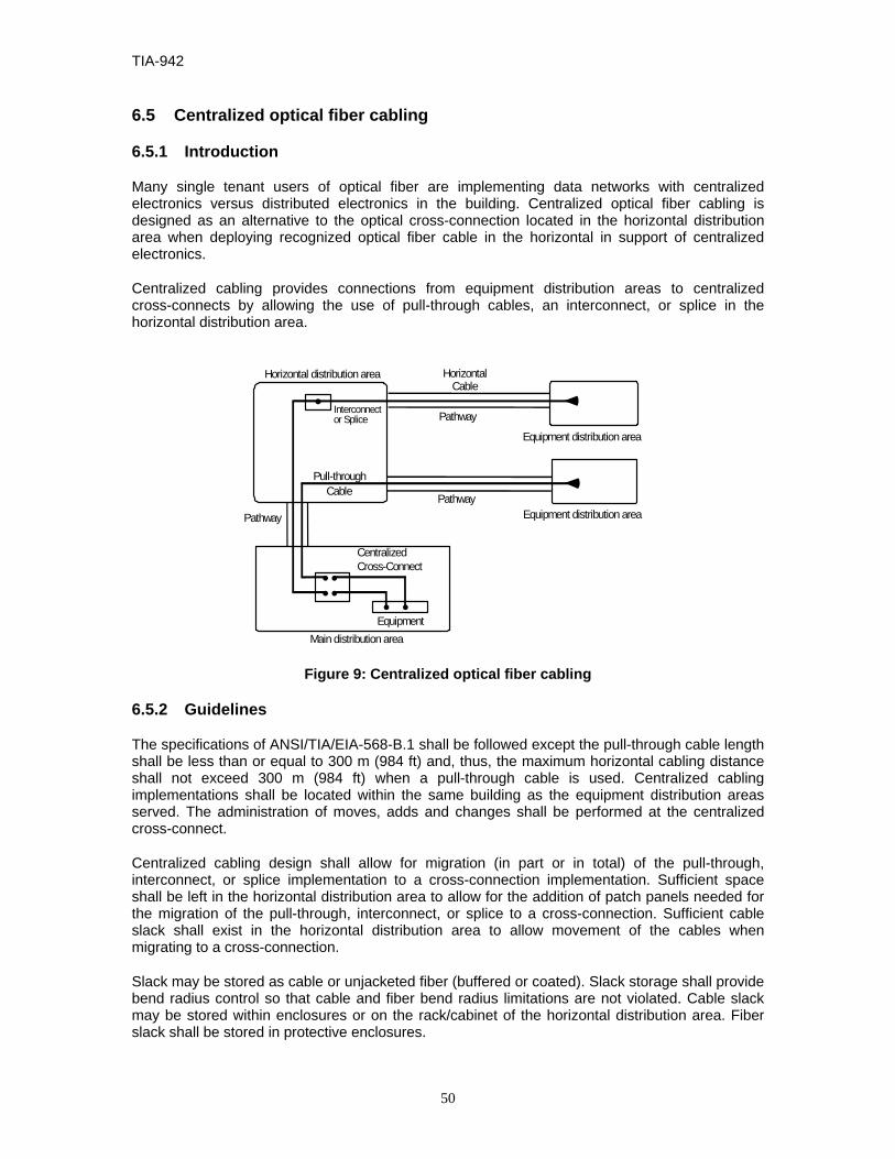
TIA-942
50
6.5 Centralized optical fiber cabling
6.5.1 Introduction
Many single tenant users of optical fiber are implementing data networks with centralized electronics versus distributed electronics in the building. Centralized optical fiber cabling is designed as an alternative to the optical cross-connection located in the horizontal distribution area when deploying recognized optical fiber cable in the horizontal in support of centralized electronics.
Centralized cabling provides connections from equipment distribution areas to centralized cross-connects by allowing the use of pull-through cables, an interconnect, or splice in the horizontal distribution area.
Interconnector Splice
•
•
Pull-throughCable
Horizontal distribution area HorizontalCable
Pathway
Pathway
CentralizedCross-Connect
Pathway
Equipment distribution area
Main distribution areaEquipment
• ••
••
Equipment distribution area
Figure 9: Centralized optical fiber cabling
6.5.2 Guidelines
The specifications of ANSI/TIA/EIA-568-B.1 shall be followed except the pull-through cable length shall be less than or equal to 300 m (984 ft) and, thus, the maximum horizontal cabling distance shall not exceed 300 m (984 ft) when a pull-through cable is used. Centralized cabling implementations shall be located within the same building as the equipment distribution areas served. The administration of moves, adds and changes shall be performed at the centralized cross-connect.
Centralized cabling design shall allow for migration (in part or in total) of the pull-through, interconnect, or splice implementation to a cross-connection implementation. Sufficient space shall be left in the horizontal distribution area to allow for the addition of patch panels needed for the migration of the pull-through, interconnect, or splice to a cross-connection. Sufficient cable slack shall exist in the horizontal distribution area to allow movement of the cables when migrating to a cross-connection.
Slack may be stored as cable or unjacketed fiber (buffered or coated). Slack storage shall provide bend radius control so that cable and fiber bend radius limitations are not violated. Cable slack may be stored within enclosures or on the rack/cabinet of the horizontal distribution area. Fiber slack shall be stored in protective enclosures.

TIA–942
51
Centralized cabling design shall allow for the addition and removal of horizontal and intrabuilding backbone fibers. The layout of the termination hardware should accommodate modular growth in an orderly manner.
The intrabuilding backbone subsystem should be designed with sufficient spare capacity to service additional outlet/connectors from the centralized cross-connect without the need to pull additional intrabuilding backbone cables. The intrabuilding backbone fiber count should be sized to deliver present and future applications to the maximum equipment distribution areas density within the area served by the horizontal distribution area. Generally, two fibers are required for each application delivered to an equipment distribution area.
Centralized cabling shall comply with the labeling requirements of ANSI/TIA/EIA-606-A and annex B of this Standard. In addition, horizontal distribution area splice and interconnect hardware shall be labeled with unique identifiers on each termination position. Field color-coding is not used at the interconnect or splice. The centralized cross-connect termination positions in the main distribution area shall be labeled as a blue field. The blue field shall move to the horizontal distribution area for each circuit that is converted to a cross-connection in the horizontal distribution area.
Centralized cabling shall be implemented to ensure the correct fiber polarity as specified in subclause 10.3.2 of ANSI/TIA/EIA-568-B.1.
6.6 Cabling transmission performance and test requirements
Transmission performance depends on cable characteristics, connecting hardware, patch cords and cross-connect wiring, the total number of connections, and the care with which they are installed and maintained. See ANSI/TIA/EIA-568-B.1, Clause 11 for field test specifications for post-installation performance measurements of cabling designed in accordance with this Standard.
TIA-942
52
7 DATA CENTER CABLING PATHWAYS
7.1 General
Except where otherwise specified, data center cabling pathways shall adhere to the specifications of ANSI/TIA-569-B.
7.2 Security for data center cabling
Telecommunications cabling for data centers shall not be routed through spaces accessible by the public or by other tenants of the building unless the cables are in enclosed conduit or other secure pathways. Any maintenance holes, pull boxes, and splice boxes shall be equipped with a lock.
Telecommunications entrance cabling for data centers should not be routed through a common equipment room (CER).
Any maintenance holes on building property or under control of the data center owner should be locked and monitored by the data center security system using a camera, remote alarm or both.
Access to pull boxes for data center cabling (entrance cabling or cabling between portions of the data center) that are located in public spaces or shared tenant spaces should be controlled. The pull boxes should also be monitored by the data center security system using a camera, remote alarm or both.
Any splice boxes for data center cabling that are located in public spaces or shared tenant spaces should be locked and monitored by the data center security system using a camera, remote alarm or both.
Entrance to utility tunnels used for telecommunications entrance rooms and other data center cabling should be locked. If the tunnels are used by multiple tenants or cannot be locked, telecommunications cabling for data centers shall be in rigid conduit or other secure pathway.
7.3 Separation of power and telecommunications cables
To minimize longitudinal coupling between power cables and twisted-pair copper cables, the separation distances outlined in this clause shall be provided. This separation is specified to accommodate the wide variety of equipment that may be present in a data center, but are not found in a typical office environment or telecommunications room.
7.3.1 Separation between electrical power and twisted-pair cables
The distances in table 2 shall be maintained between electrical power cables and twisted-pair cables. Electrical codes may require a barrier or greater separation than specified in table 2. Refer to NFPA 70, article 800 or applicable electrical code for additional information.

TIA–942
53
Table 2: Data center separation between twisted-pair and shielded power cables
Quantity of circuits Electrical Circuit Type Separation
Distance (mm) Separation
Distance (in) 1 -15 20A 110/240V 1-phase shielded or
unshielded Refer to 569B
annex C Refer to 569B
annex C 16 - 30 20A 110/240V 1-phase shielded 50 mm 2 in 31 - 60 20A 110/240V 1-phase shielded 100 mm 4 in 61-90 20A 110/240V 1-phase shielded 150 mm 6 in 91+ 20A 110/240V 1-phase shielded 300 mm 12 in 1+ 100A 415V 3-phase shielded feeder 300 mm 12 in
If the power cables are unshielded, then the separation distances provided in table 2 shall be doubled. However, these distances can apply to unshielded power cables if either the power cables or data cables are installed in bonded and grounded metal tray. The side or the bottom of the metal tray shall separate the power cables from the twisted-pair cables, this separation surface should be solid metal. Refer to NEMA VE 2-2001 for additional information on cable tray installation guidelines.
The shielding shall completely surround the cable (except at the receptacle) and shall be properly bonded and grounded in accordance with the applicable electrical codes.
There are no requirements for separation of power and telecommunications cabling crossing at right angles, except the separation requirements mandated by applicable electrical codes.
No separation distance is required when either the data cables or the power cables are enclosed in metallic raceway or conduit that meets the following requirements:
- the metallic raceway or conduit shall completely enclose the cables and be continuous;
- the metallic raceway or conduit shall be properly bonded and grounded in accordance with the applicable electrical codes;
- the raceway or conduit shall be at least 1 mm (0.04 in) thick if made of galvanized (low carbon) steel or 2 mm (0.08 in) thick if made of aluminum.
7.3.2 Practices to accommodate power separation requirements
It is normally possible to meet the recommended separation distances through thoughtful design and installation practices.
Branch circuits in data centers should be in watertight flexible metal conduit. Feeder circuits to power distribution units and panels should be installed in solid metal conduit. If the feeder circuits are not in solid metal conduit, they should be in watertight flexible metal conduit.
In data centers that use overhead cable trays, the normal separation distances provided by standard practices provides adequate separation. As specified in ANSI/TIA-569-B, a minimum of 300 mm (12 in) access headroom between the top of a tray or runway and the bottom of the tray or runway above shall be provided and maintained. This provides adequate separation if the electrical cables are shielded or if the power cable tray meets the specifications of the subclause 7.3.1 and is above the telecommunications cable tray or runway.
In data centers that employ access floor systems, adequate separation of power and telecommunications cabling can be accommodated through the following measures:

TIA-942
54
- in the main aisles, allocate separate aisles for power and telecommunications cabling, if possible;
- where it is not possible to allocate separate aisles for power and telecommunications cabling in the main aisles, then provide both horizontal and vertical separation of power and telecommunications cables. Provide horizontal separation by allocating different rows of tiles in the main aisles for power and telecommunications cabling, with the power and telecommunications cables as far apart from each other as possible. Additionally, provide vertical separation by placing the telecommunications cabling in cable trays or baskets as far above the power cables as possible, preferably with the top of the cable tray or basket 20 mm (0.75 in) below the bottom of the access floor tile;
- in the equipment cabinet aisles, allocate separate aisles for power and telecommunications cabling. Refer to subclause 5.11.2 for additional information on “hot” and “cold” aisles.
7.3.3 Separation of fiber and copper cabling
Fiber and copper cabling in cable trays and other jointly used pathways should be separated so that it improves administration, operation, and minimize damage to smaller diameter fiber cables. Physical barriers between the two types of cables are not necessary.
Where it is not practical to separate fiber and copper cables, fiber cables should be on top of copper cables.
7.4 Telecommunications entrance pathways
7.4.1 Entrance pathway types
Telecommunications entrance pathways for data centers should be located underground. Aerial entrance pathways for telecommunications service entrance pathways are not recommended because of their vulnerability due to physical exposure.
7.4.2 Diversity Refer to ANSI/TIA-569-B for information regarding entrance pathway diversity.
7.4.3 Sizing
The number of entrance conduits required depends on the number of access providers that will provide service to the data center, and the number and type of circuits that the access providers will provide. The entrance pathways should also have adequate capacity to handle growth and additional access providers.
Each access provider should have at least one 100 mm (4 in) trade size conduit at each entrance point. Additional conduits may be required for campus. Conduits used for optical fiber entrance cables should have three innerducts [two 38 mm (1.5 in) and one 25 mm (1.0 in) or three 33 mm (1.25 in)].
7.5 Access floor systems
7.5.1 General
Access floor systems, also known as raised floor systems, should be used in data centers that support equipment that is designed to be cabled from below.

TIA–942
55
Cables shall not be left abandoned under the access floor. Cables shall be terminated on at least one end in the main distribution area or a horizontal distribution area, or shall be removed.
For additional information on rack and cabinet installation with access flooring systems, refer to subclause 5.11.
7.5.2 Cable trays for telecommunications cabling
Telecommunications cabling under the access floor shall be in ventilated cable trays that do not block airflow. See ANSI/TIA-569-B for further cable tray design considerations. Under floor cable trays may be installed in multiple layers to provide additional capacity. Metallic cable tray shall be bonded to the data center grounding infrastructure. The cable tray should have a maximum depth of 150 mm (6 in).
Under-floor cable tray routing should be coordinated with other under floor systems during the planning stages of the building. Refer to NEMA VE 2-2001 for recommendations regarding installation of cable trays.
7.5.3 Access floor performance requirements
Access flooring shall meet the performance requirements of ANSI/TIA-569-B subclause 8.5 and annex B.2.
Access floors for data centers should use a bolted stringer understructure, as they are more stable over time than stringerless systems. Additionally, access floor stringers should be 1.2 m (4 ft) long installed in a “herringbone” pattern to improve stability. Pedestals should be bolted to the subfloor for added stability.
7.5.4 Floor tile cut edging
Access floor tile cuts should have edging or grommets along all cut edges. If the edging or grommets are higher than the surface of the access floor, they shall be installed as not to interfere with placement of racks and cabinets. The edging or grommets shall not be placed where the racks and cabinets normally contact the surface of the access floor.
In the case of floor discharge HVAC systems, floor tile cuts should be limited in both size and quantity to ensure proper airflow. It is recommended that the HVAC system be properly balanced once all equipment racks, cabinets, etc are in-place. The HVAC system should be re-balanced with the addition of floor cuts, equipment racks, cabinets, etc.
7.5.5 Cable types under access floors
In some jurisdictions, plenum cable is the minimum requirement for telecommunications cabling under computer room access floors. Consult the AHJ before deciding on the type of cable to use under access floors.
NOTE – This standard references applicable requirements relating to fire, health and safety. In addition, consider the selection of cable types and fire suppression practices that minimize damage in the event of fire.

TIA-942
56
7.6 Overhead cable trays
7.6.1 General
Overhead cable tray systems may alleviate the need for access floors in data centers that do not employ floor-standing systems that are cabled from below.
Overhead cable trays may be installed in several layers to provide additional capacity. Typical installations include two or three layers of cable trays, one for power cables and one or two for telecommunications cabling. One of the cable tray layers typically has brackets on one side that hold the data center grounding infrastructure. These overhead cable trays are often supplemented by a duct or tray system for fiber patch cables. The fiber duct or tray may be secured to the same hanging rods used to support the cable trays.
Cables shall not be left abandoned in overhead cable trays. Cables shall be terminated on at least one end in the main distribution area or a horizontal distribution area, or shall be removed.
In aisles and other common spaces in internet date centers, co-location facilities, and other shared tenant data centers, overhead cable trays should have solid bottoms or be placed at least 2.7 m (9 ft) above the finished floor to limit accessibility or be protected through alternate means from accidental and/or intentional damage.
The maximum recommended depth of any cable tray is 150 mm (6 in).
7.6.2 Cable tray support
Overhead cable trays should be suspended from the ceiling. If all racks and cabinets are of uniform height, the cable trays may be attached to the top of racks and cabinets, but this is not a recommended practice because suspended cable trays provide more flexibility for supporting cabinets and racks of various heights, and provide more flexibility for adding and removing cabinets and racks.
Typical cable tray types for overhead cable installation include telco-type cable ladders, center spine cable tray, or wire basket cable tray. If required by prevailing code, adjacent sections of cable tray shall be bonded together and grounded per AHJ, and shall be listed by a nationally recognized testing laboratory (NRTL) for this purpose. The cable tray system should be bonded to the data center grounding infrastructure.
7.6.3 Coordination of cable tray routes
Planning of overhead cable trays for telecommunications cabling should be coordinated with architects mechanical engineers, and electrical engineers that are designing lighting, plumbing, air ducts, power, and fire protection systems. Lighting fixtures and sprinkler heads should be placed between cable trays, not directly above cable trays.

TIA–942
57
8 DATA CENTER REDUNDANCY
8.1 Introduction
Data Centers that are equipped with diverse telecommunications facilities may be able to continue their function under catastrophic conditions that would otherwise interrupt the data center’s telecommunications service. This Standard includes four tiers relating to various levels of availability of the data center facility infrastructure. Information on infrastructure tiers can be found in annex G. The Figure 10 illustrates various redundant telecommunications infrastructure components that can be added to the basic infrastructure.
The reliability of the communications infrastructure can be increased by providing redundant cross-connect areas and pathways that are physically separated. It is common for data centers to have multiple access providers providing services, redundant routers, redundant core distribution and edge switches. Although this network topology provides a certain level of redundancy, the duplication in services and hardware alone does not ensure that single points of failure have been eliminated.
Primary EntranceRoom
(Tier 1 and higher)
Horiz DistArea
Equip DistArea
ComputerRoom
Horiz DistAreaZone Dist Area
Offices, OperationsCenter, Support
Rooms
Telecom Room
OptionalCabling
Main Dist Area(Tier 1 and higher)
Horiz DistArea
Equip DistArea
Equip DistArea
SecondaryEntrance Room
(Tier 3 and higher)
Secondary DistArea
(Optional for Tier 4)
Access Providers
Primary CustomerMaintenance Hole(Tier 1 and higher)
SecondaryCustomer
Maintenance Hole(Tier 2 and higher)
Tier 1
Tier 3
Tier 1
Tier 4
Tier 3
Tier 2
Tier 4
Tier 3
Tier 4
DataCenter
Tier 3
Cabling
Access Providers
Figure 10: Telecommunications infrastructure redundancy
8.2 Redundant maintenance holes and entrance pathways
Multiple entrance pathways from the property line to the entrance room(s) eliminate a single point of failure for access provider services entering the building. These pathways will include customer-owned maintenance holes where the access provider conduits do not terminate at the building wall. The maintenance holes and entrance pathways should be on opposite sides of the building and be at least 20 m (66 ft) apart.
TIA-942
58
In data centers with two entrance rooms and two maintenance holes, it is not necessary to install conduits from each entrance room to each of the two maintenance holes. In such a configuration, each access provider is typically requested to install two entrance cables, one to the primary entrance room through the primary maintenance hole, and one to the secondary entrance room through the secondary maintenance hole. Conduits from the primary maintenance hole to the secondary entrance room and from the secondary maintenance hole to the primary maintenance hole provide flexibility, but are not required.
In data centers with two entrance rooms, conduits may be installed between the two entrance rooms to provide a direct path for access provider cabling between these two rooms (for example, to complete a SONET or SDH ring).
8.3 Redundant access provider services
Continuity of telecommunications access provider services to the data center can be ensured by using multiple access providers, multiple access provider central offices, and multiple diverse pathways from the access provider central offices to the data center.
Utilizing multiple access providers ensures that service continues in the event of a access provider-wide outage or access provider financial failure that impacts service.
Utilizing multiple access providers alone does not ensure continuity of service, because access providers often share space in central offices and share rights-of-way.
The customer should ensure that its services are provisioned from different access provider central offices and the pathways to these central offices are diversely routed. These diversely routed pathways should be physically separated by at least 20 m (66 ft) at all points along their routes.
8.4 Redundant entrance room
Multiple entrance rooms may be installed for redundancy rather than simply to alleviate maximum circuit distance restrictions. Multiple entrance rooms improve redundancy, but complicate administration. Care should be taken to distribute circuits between entrance rooms.
Access providers should install circuit provisioning equipment in both entrance rooms so that circuits of all required types can be provisioned from either room. The access provider provisioning equipment in one entrance room should not be subsidiary to the equipment in the other entrance room. The access provider equipment in each entrance room should be able to operate in the event of a failure in the other entrance room.
The two entrance rooms should be at least 20 m (66 ft) apart and be in separated fire protection zones. The two entrance rooms should not share power distribution units or air conditioning equipment.
8.5 Redundant main distribution area
A secondary distribution area provides additional redundancy, but at the cost of complicating administration. Core routers and switches should be distributed between the main distribution area and secondary distribution area. Circuits should also be distributed between the two spaces.
A secondary distribution area may not make sense if the computer room is one continuous space, as a fire in one portion of the data center will likely require that the entire data center be shut down. The secondary distribution area and main distribution area should be in different fire

TIA–942
59
protection zones, be served by different power distribution units, and be served by different air conditioning equipment.
8.6 Redundant backbone cabling
Redundant backbone cabling protects against an outage caused by damage to backbone cabling. Redundant backbone cabling may be provided in several ways depending on the degree of protection desired.
Backbone cabling between two spaces, for example, a horizontal distribution area and a main distribution area, can be provided by running two cables between these spaces, preferably along different routes. If the data center has both a main distribution area and a secondary distribution area, redundant backbone cabling to the horizontal distribution area is not necessary, though the routing of cables to the main distribution area and secondary distribution area should follow different routes.
Some degree of redundancy can also be provided by installing backbone cabling between horizontal distribution areas. If the backbone cabling from the main distribution area to horizontal distribution area is damaged, connections can be patched through another horizontal distribution area.
8.7 Redundant horizontal cabling
Horizontal cabling to critical systems can be diversely routed to improved redundancy. Care should be taken not to exceed maximum horizontal cable lengths when selecting paths.
Critical systems can be supported by two different horizontal distribution areas as long as maximum cable length restrictions are not exceeded. This degree of redundancy may not provide much more protection than diversely routing the horizontal cabling if the two horizontal distribution areas are in the same fire protection zone.

TIA-942
60
ANNEX A (INFORMATIVE) CABLING DESIGN CONSIDERATIONS
This annex is informative only and is not part of this Standard.
A.1 Cabling application distances
The cabling distances presented here are informative only.
The maximum supportable distances proposed in this annex are application and media dependent.
The use of 100-Ohm twisted-pair cable (4-pair category 6 is recommended) is based on the following applications:
- 1000 Mb/s LAN connections;
- termination of T1 and lower speed circuits in the end equipment area;
- facilities management and monitoring;
- out-of-band management;
- power management;
- security systems.
The use of 75-ohm coaxial (734 type) cable is based on the provisioning of T-3 circuits from the access provider to the end equipment area.
The use of current 62.5/125 µm multimode fiber (160/500 MHz•km) is based on the following applications:
- 1000 Mb/s Ethernet (1000BASE-SX);
- 100 Mb/s (133 MBaud) Fibre Channel (100-M6-SN-I);
- 200 Mbps (266 MBaud) Fibre Channel (200-M6-SN-I).
The use of current 50/125 µm multimode fiber (500/500 MHz•km) is based on the following applications:
- 1000 Mb/s Ethernet (1000BASE-SX);
- 100 Mb/s (133 MBaud) Fibre Channel (100-M5-SN-I);
- 200 Mbps (266 MBaud) Fibre Channel (200-M5-SN-I).
The use of 850-nm laser-optimized 50/125 µm multimode fiber (1500/500 MHz•km; 2000 MHz•km effective modal bandwidth) is based on the following applications:
- 1000 Mb/s Ethernet (1000BASE-SX);

TIA–942
61
- 10 Gb/s Ethernet (10GBASE-S);
- 100 Mb/s (133 MBaud) Fibre Channel (100-M5-SN-I);
- 200 Mbps (266 MBaud) Fibre Channel (200-M5-SN-I);
- 1200 Mbps (1062 MBaud) Fibre Channel (1200-M5E-SN-I).
The use of single-mode fiber, as per ANSI/TIA/EIA-568-B.3, is based on the following applications:
- 10 Gb/s and higher LAN & SAN connections;
- distances in excess of those recommended for 850-nm laser-optimized 50/125 µm multimode fiber.
A.1.1 T-1, E-1, T-3 and E-3 circuit distances
The following table 3 provides the maximum circuit distances for T-1, T-3, E-1, and E-3 circuits with no adjustments for intermediate patch panels or outlets between the circuit demarcation point and the end equipment. These calculations assume that there is no customer DSX panel between the access provider demarcation point (which may be a DSX) and the end equipment. The access provider DSX panel is not counted in determining maximum circuit lengths.
Table 3: Maximum circuit distances with no customer DSX panel
Circuit type Category 3 UTP
Category 5e & 6 UTP
734 Type Coaxial
735 Type Coaxial
T-1 170 m (557 ft)
206 m (677 ft) - -
CEPT-1 (E-1)
126 m (412 ft)
158m (517 ft)
395m (1297 ft)
177 m (580 ft)
T-3 - - 160 m (524 ft)
82 m (268 ft)
CEPT-3 (E-3) - - 175 m
(574 ft) 90 m
(294 ft)
NOTE: The distances shown in table 3 are for the specific applications used in data centers and may be different from the distances supported for various applications in TIA-568-B.
Repeaters can be used to extend circuits beyond the lengths specified above.
These circuit distances should be adjusted for attenuation losses caused by a DSX panel between the access provider demarcation point (which may be a DSX panel) and the end equipment. The following table 4 provides the reduction caused by DSX panels in maximum circuit distances for T-1, T-3, E-1, and E-3 circuits over the recognized media type.

TIA-942
62
Table 4: Reduction in circuit distances for customer DSX panel
Circuit type Category 3 UTP
Category 5e & 6 UTP
734 Type Coaxial
735 Type Coaxial
T-1 11 m (37 ft)
14 m (45 ft) - -
CEPT-1 (E-1)
10 m (32 ft)
12 m (40 ft)
64 m (209 ft)
28 m (93 ft)
T-3 - - 13 m (44 ft)
7 m (23 ft)
CEPT-3 (E-3) - - 15 m
(50 ft) 8 m
(26 ft)
Maximum circuit distances should be adjusted for attenuation losses caused by intermediate patch panels and outlets. The following table 5 provides the reduction in maximum circuit distances for T-1, T-3, E-1, and E-3 circuits over the recognized media type.
Table 5: Reduction in circuit distances per patch panel or outlet
Circuit type Category 3 UTP
Category 5e & 6 UTP
734 Type Coaxial
735 Type Coaxial
T-1 4.0 m (13.0 ft)
1.9 m (6.4 ft) - -
CEPT-1 (E-1)
3.9 m (12.8 ft)
2.0 m (6.4 ft)
22.1 m (72.5 ft)
9.9 m (32.4 ft)
T-3 - - 4.7 m (15.3 ft)
2.4 m (7.8 ft)
CEPT-3 (E-3) - - 5.3 m
(17.5 ft) 2.7 m (8.9 ft)
In the typical data center, there are a total of 3 connections in the backbone cabling, 3 connections in the horizontal cabling and no DSX panels between the access provider demarcation point and the end equipment:
Backbone cabling:
• one connection in the entrance room,
• two connections in the main cross-connect,
Horizontal cabling:
• two connections in the horizontal cross-connect, and
• an outlet connection at the equipment distribution area.
This ‘typical’ configuration corresponds to the typical data center with an entrance room, main distribution area, one or more horizontal distribution areas, and no zone distribution areas. Maximum circuit lengths for the typical data center configuration are in the following table 6. These maximum circuit lengths include backbone cabling, horizontal cabling, and all patch cords or jumpers between the access provider demarcation point and the end equipment.

TIA–942
63
Table 6: Maximum circuit distances for the typical data center configuration
Circuit type Category 3 UTP
Category 5e & 6 UTP
734 Type Coaxial
735 Type Coaxial
T-1 146 m (479 ft)
198 m (648 ft) - -
CEPT-1 (E-1)
102 m (335 ft)
146 m (478 ft)
263 m (862 ft)
117m (385 ft)
T-3 - - 132 m (432 ft)
67 m (221 ft)
CEPT-3 (E-3) - - 143 m
(469 ft) 73 m
(240 ft)
With maximum horizontal cable lengths, maximum patch cord lengths, no customer DSX, and no zone outlets, the maximum backbone cable lengths for a ‘typical’ data center where T-1, E-1, T-3, or E-3 circuits can be provisioned to equipment anywhere in the data center are shown in the following table 7. This ‘typical’ configuration assumes that the entrance room, main distribution area, and horizontal distribution areas are separate rather than combined. The maximum backbone cabling distance is the sum of the length of cabling from the entrance room to the main distribution area and from the main distribution area to the horizontal distribution area.
Table 7: Maximum backbone for the typical data center configuration
Circuit type Category 3 UTP
Category 5e & 6 UTP
734 Type Coaxial
735 Type Coaxial
T-1 8 m (27 ft)
60 m (196 ft) - -
CEPT-1 (E-1)
0 m (0 ft)
8 m (26 ft)
148 m (484 ft)
10m (33 ft)
T-3 - - 17 m (55 ft)
0 m (0 ft)
CEPT-3 (E-3) - - 28 m
(92 ft) 0 m (0 ft)
These calculations assume the following maximum patch cord lengths in the ‘typical’ data center:
- 10 m (32.8 ft) for UTP and fiber in the entrance room, main distribution area, and horizontal distribution area;
- 5 m (16.4 ft) for 734-type coaxial cable in the entrance room, main distribution area, and horizontal distribution area;
- 2.5 m (8.2 ft) for 735-type coaxial cable in the entrance room, main distribution area, and horizontal distribution area.
Due to the very short distances permitted by category 3 UTP cabling and 735 type coaxial cable for T-1, T-3, E-1, and E-3 circuits, category 3 UTP and 735-type coaxial cables are not recommended for supporting these types of circuits.
Backbone cabling distances can be increased by limiting the locations where T-1, E-1, T-3, and E-3 circuits will be located (for example only in the main distribution area or locations served by horizontal cabling terminated in the main distribution area).
Other options include provisioning circuits from equipment located in the main distribution area or horizontal distribution area.

TIA-942
64
A.1.2 EIA/TIA-232 and EIA/TIA-561 console connections
The recommended maximum distances for EIA-TIA-232-F and EIA/TIA-561/562 console connections up to 20 kb/s are:
- 23.2 m (76.2 ft) over category 3 unshielded twisted-pair cable;
- 27.4 m (89.8 ft) over category 5e or category 6 unshielded twisted-pair cable.
The recommended maximum distances for EIA-TIA-232-F and EIA/TIA-561/562 console connections up to 64 kb/s are:
- 8.1 m (26.5 ft) over category 3 unshielded twisted-pair cable;
- 9.5 m (31.2 ft) over category 5e or category 6 unshielded twisted-pair cable.
Recommended maximum distances over shielded twisted-pair cables are one half of the distances permitted over unshielded twisted-pair cables.
A.1.3 Other application distances
As 1 and 10 Gigabit fiber applications are introduced into networks the physical limitations and properties of optical fiber introduce new challenges for a network designer. Due to the increased data rate, fiber effects, such as dispersion, become a factor in the achievable distances and numbers of connectors used in fiber optic link designs. This leaves the network designer with new decisions and trade-offs that they must understand and overcome. Refer to the information provided in ANSI/TIA/EIA-568-B.1 and Addendum 3 to ANSI/TIA/EIA-568-B.1 regarding supportable distances and channel attenuation for optical fiber applications by fiber type.
A.2 Cross-connections
In the entrance room, main distribution area and horizontal distribution area, jumper and patch cord lengths used for cross-connection to backbone cabling should not exceed 20 m (66 ft).
The only exception to these length restrictions should be in the case of 75-ohm coaxial cables, for DS-3 patching, the maximum length should be 5 m (16.4 ft) for type 734 coaxial and 2.5 m (8.2 ft) for type 735 coaxial in the entrance room, main cross-connect, and horizontal cross-connects.
A.3 Separation of functions in the main distribution area
The main distribution area should have separate racks for copper-pair, coaxial cable, and optical fiber distribution unless the data center is small and the main cross-connect can fit in one or two racks. Separate patching bays for copper-pair cables, coaxial cables, and optical fiber cables simplify management and serves to minimize the size of each type of patching bay. Arrange patching bays and equipment in close proximity to minimize patch cord lengths.
A.3.1 Twisted-pair main cross-connect
The twisted-pair main cross-connect (MC) supports twisted-pair cable for a wide range of applications including low speed circuits, T-1, E-1, consoles, out-of-band management, KVM, and LANs.
Consider installing category 6 twisted-pair cabling for all copper-pair cabling from the MC to the intermediate cross-connects (ICs) and HCs, as this will provide maximum flexibility for supporting a wide variety of applications. High pair count (25-pair or higher) category 3 twisted-pair

TIA–942
65
backbone is satisfactory for cabling from the MC to the HC and low-speed circuit demarcation area in the entrance room. Cabling from the E-1/T-1 demarcation area in the entrance room should be 4-pair category 5e or category 6 twisted-pair cable.
The type of terminations in the MC (IDC connecting hardware or patch panels) depends on the desired density and where the conversion from 1- and 2-pair access provider cabling to 4-pair computer room structured cabling occurs:
- if the conversion from 1- and 2-pair access provider cabling occurs in the entrance room, then copper-pair cable terminations in the MC are typically on patch panels. This is the recommended configuration;
- if the conversion from 1- and 2-pair access provider cabling occurs in the MC, then copper-pair cable terminations in the MC should be on IDC connecting hardware.
A.3.2 Coaxial main cross-connect
The coaxial MC supports coaxial cable for T-3 and E-3 cabling (two coaxial cables per circuit). All coaxial cabling should be 734-type coaxial cable.
Termination of coaxial cables should be on patch panels with 75-ohm BNC connectors. The BNC connectors should be female-BNC on both the front and back of the patch panels.
A.3.3 Optical fiber main cross-connect
The fiber MC supports optical fiber cable for local area networks, storage area networks, metropolitan area networks, computer channels, and SONET circuits.
Termination of fiber cables should be on fiber patch panels.
A.4 Separation of functions in the horizontal distribution area
Horizontal distribution areas should have separate cabinets or racks for copper-pair, coaxial cable, and optical fiber distribution unless the horizontal cross-connect is small and only requires one or two racks. Separate patching bays for copper-pair cables, coaxial cables, and optical fiber cables simplify management and minimize the size of each type of patching bay. Arrange patching bays and equipment in close proximity to minimize patch cord lengths.
The use of a single type of cable simplifies management and improves flexibility to support new applications. Consider installing only one type of twisted-pair cable for horizontal cabling, (for example all category 5e or all category 6 UTP), rather than installing different types of twisted-pair cables for different applications.
A.5 Cabling to telecommunications equipment
The length of the cable used to connect voice telecommunications equipment (such as PBX’s) directly to the main distribution area should not exceed 30 m (98 ft).
The length of the cable used to connect voice telecommunications equipment (such as PBX’s) directly to the horizontal distribution area should not exceed 30 m (98 ft).

TIA-942
66
A.6 Cabling to end equipment
Equipment cord lengths from the ZDA should be limited to a maximum of 22 m (72 ft) in the case of copper or fiber optic cabling.
If individual telecommunications outlets are located on the same equipment rack or cabinet as the equipment served in lieu of a ZDA, equipment cord lengths should be limited to 5 m (16 ft).
A.7 Fiber design consideration
High termination density can be achieved using multi-fiber increments and the use of multi-fiber connectors. If cable lengths can be accurately pre-calculated, pre-terminated multi-fiber ribbon assemblies can reduce installation time. In these cases, consideration of the effects of additional connections should be considered to ensure overall fiber system performance. High data-rate end equipment may accommodate multi-fiber connectors directly.
A.8 Copper design consideration
The patch panels should provide adequate space for labeling of each patch panel with its identifier as well as labeling each port as per annex B and ANSI/TIA/EIA-606-A requirements.

TIA–942
67
ANNEX B (INFORMATIVE) TELECOMMUNICATIONS INFRASTRUCTURE ADMINISTRATION
This annex is informative only and is not part of this Standard.
B.1 General
Data centers should adhere to ANSI/TIA/EIA-606-A with the exceptions noted in this Standard.
B.2 Identification scheme for floor space
Floor space should track the data center grid. Most data centers will require at least two letters and two numeric digits to identify every 600 mm x 600 mm (or 2 ft x 2 ft) floor tile. In such data centers, the letters will be AA, AB, AC… AZ, BA, BB, BC… and so on. For an example, see figure 11.
AK AL AM AN AO AP AQ AR AS AT AU AV AW AX AY AZ BA BB BC BDAE AF AG AH AI AJAC ADAB
09
10
11
12
13
AA
01
02
03
04
05
06
07
08
"X" COORDINATE
"Y" COORDINATE
Figure 11: Sample floor space identifiers
B.3 Identification scheme for racks and cabinets
All racks and cabinets should be labeled in the front and back.
In computer rooms with access floors, label cabinets and racks using the data center grid. Each rack and cabinet should have a unique identifier based on floor tile coordinates. If cabinets rest on more than one tile, the grid location for the cabinets can be determined by using the same corner on every cabinet (e.g., the right front corner).
The cabinet or rack ID should consist of one or more letters followed by one or more numbers. The numeric portion of the ID will include leading 0’s. So the cabinet whose front right corner is at tile AJ05 will be named AJ05.

TIA-942
68
In data centers with multiple floors, the floor number should be added as a prefix to the cabinet number. For example, 3AJ05 for the cabinet whose front right corner is at tile AJ05 on the 3rd floor of the data center. A sample floor space administration schema follows:
nx1y1
Where:
n = Where data center space is present in more than one floor in a building, one or more numeric characters designating the floor on which the space is located.
x1y1 = One or two alphanumeric characters followed by two alphanumeric characters designating the location on the floor space grid where the right front corner of the rack or cabinet is located. In figure 12, the Sample Cabinet is located at AJ05.
AK AL AM AN AO AP AQ AR AS AT AU AV AW AX AY AZ BA BB BC BDAE AF AG AH AI AJAC ADAB
09
10
11
12
13
AA
01
02
03
04
05
06
07
08
"X" COORDINATE
"Y" COORDINATE
SAMPLE CABINET
RIGHTFRONT
CORNER
Figure 12: Sample rack/cabinet identifier
In computer rooms without access floors, use row number and position within the row to identify each rack and cabinet.
In Internet data centers and co-location facilities, where the computer room is subdivided into customer cages and rooms, the identification scheme can use cage/room names and cabinet or rack number within the cage/room.
B.4 Identification scheme for patch panels
1) Patch Panel Identifier
The identification scheme for patch panels should include cabinet or rack name and one or more characters that indicate the patch panel position in the cabinet or rack. Horizontal wire management panels do not count when determining patch panel position. If a rack has more than 26 panels, then two characters will be required to identify the patch panel. A sample patch panel administration schema follows:
x1y1-a
Where:
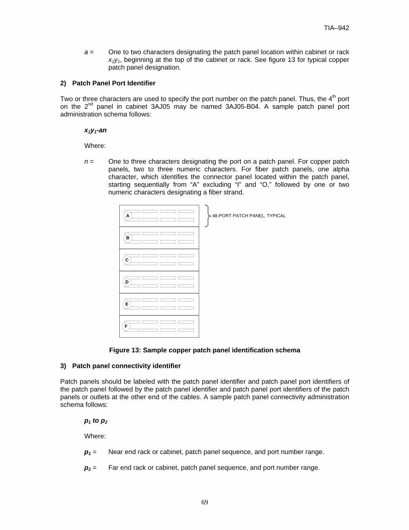
TIA–942
69
a = One to two characters designating the patch panel location within cabinet or rack x1y1, beginning at the top of the cabinet or rack. See figure 13 for typical copper patch panel designation.
2) Patch Panel Port Identifier
Two or three characters are used to specify the port number on the patch panel. Thus, the 4th port on the 2nd panel in cabinet 3AJ05 may be named 3AJ05-B04. A sample patch panel port administration schema follows:
x1y1-an
Where:
n = One to three characters designating the port on a patch panel. For copper patch panels, two to three numeric characters. For fiber patch panels, one alpha character, which identifies the connector panel located within the patch panel, starting sequentially from “A” excluding “I” and “O,” followed by one or two numeric characters designating a fiber strand.
48-PORT PATCH PANEL, TYPICALA
B
C
D
E
F
Figure 13: Sample copper patch panel identification schema
3) Patch panel connectivity identifier
Patch panels should be labeled with the patch panel identifier and patch panel port identifiers of the patch panel followed by the patch panel identifier and patch panel port identifiers of the patch panels or outlets at the other end of the cables. A sample patch panel connectivity administration schema follows:
p1 to p2
Where:
p1 = Near end rack or cabinet, patch panel sequence, and port number range.
p2 = Far end rack or cabinet, patch panel sequence, and port number range.

TIA-942
70
Consider supplementing ANSI/TIA/EIA-606-A cable labels with sequence numbers or other identifiers to simplify troubleshooting. For example, the 24-port patch panel with 24 category 6 cables from the MDA to HDA1 could include the label above, but could also include the label ‘MDA to HDA1 Cat 6 UTP 1 – 24’.
AK AL AM AN AO AP AQ AR AS AT AU AV AW AX AY AZ BA BB BC BDAE AF AG AH AI AJAC ADAB
09
10
11
12
13
AA
01
02
03
04
05
06
07
08
"X" COORDINATE
"Y" COORDINATE
SAMPLE CABINET
RIGHTFRONT
CORNER
RIGHTFRONTCORNER
Cat 6 x 24
Figure 14: Sample 8-position modular patch panel labeling – Part I For example, figure 15 shows a label for a 24-position modular patch panel with 24 category 6 cables interconnecting cabinet AJ05 to AQ03 as shown in figure 14.
01 02 03 04 05 06 07 08 09 10 11 12 13 14 15 16 17 18 19 20 21 22 23 24
AJ05-A to AQ03-B Ports 01-24
A A
Figure 15: Sample 8-position modular patch panel labeling – Part II
B.5 Cable and patch cord identifier
Cables and patch cords should be labeled on both ends with the name of the connection at both ends of the cable.
Consider color-coding patch cables by application and type. A sample cable and patch cord administration schema follows:
p1n / p2n
Where:
TIA–942
71
p1n = The near end rack or cabinet, patch panel sequence, and port designator assigned to that cable.
p2n = The far end rack or cabinet, patch panel sequence, and port designator assigned to that cable.
For example, the cable connected to first position of the patch panel shown in figure 15 may contain the following label:
AJ05-A01 / AQ03-B01
and the same cable at cabinet AQ03 would contain the following label:
AQ03-B01 / AJ05-A01

TIA-942
72
ANNEX C (INFORMATIVE) ACCESS PROVIDER INFORMATION
This annex is informative only and is not part of this Standard.
C.1 Access provider coordination
C.1.1 General
Data center designers should coordinate with local access providers to determine the access providers’ requirements and to ensure that the data center requirements are provided to the access providers.
C.1.2 Information to provide to access providers
Access providers will typically require the following information for planning entrance rooms for a data center:
- address of the building;
- general information concerning other uses of the building, including other tenants;
- plans of telecommunications entrance conduits from the property line to the entrance room, including location of maintenance holes, hand holes, and pull boxes;
- assignment of conduits and innerducts to the access provider;
- floor plans for the entrance facilities;
- assigned location of the access providers protectors, racks, and cabinets;
- routing of cables within entrance room (under access floor, overhead cable ladders, other);
- expected quantity and type of circuits to be provisioned by the access provider;
- date that the access provider will be able to install entrance cables and equipment in the entrance room;
- requested location and interface for demarcation of each type of circuit to be provided by the access provider;
- requested service date;
- name, telephone number, and email address of primary customer contact and local site contact.
C.1.3 Information that the access providers should provide
The access provider should provide the following information:
- space and mounting requirements for protectors on copper-pair cables;
- quantity and dimensions of access provider racks and cabinets;

TIA–942
73
- power requirements for equipment, including receptacle types;
- service clearances;
- installation and service schedule.
C.2 Access provider demarcation in the entrance room
C.2.1 Organization
The entrance room will have up to four separate areas for access provider demarcation:
- demarcation for low-speed copper-pair circuits, including DS-0, ISDN BRI, and telephone lines;
- demarcation for high-speed DS-1 (T-1 or fractional T-1, ISDN PRI) or CEPT-1 (E-1) copper-pair circuits;
- demarcation for circuits delivered on coaxial cable including DS-3 (T-3) and CEPT-3 (E-3);
- demarcation for optical fiber circuits (for example, SONET OC-x, SDH STM-x, FDDI, Fast Ethernet, Gigabit Ethernet, 10 Gigabit Ethernet).
Ideally, all access providers provide demarcation for their circuits in the same location rather than in their own racks. This simplifies cross-connects and management of circuits. The centralized location for demarcation to all access providers is often called meet-me areas or meet-me racks. There should be separate meet-me or demarcation areas or racks for each type of circuit; low speed, E-1/T-1, E-3/T-3, and optical fiber. Cabling from the computer room to the entrance room should terminate in the demarcation areas.
If an access provider prefers to demarcate their services in their racks, the customer can install tie-cables from that access provider’s demarcation point to the desired meet-me/demarcation area.
C.2.2 Demarcation of low-speed circuits
Access providers should be asked to provide demarcation of low-speed circuits on IDC connecting hardware. While service providers may prefer a specific type of IDC connecting hardware (e.g. 66 block), they may be willing to hand off circuits on another type of IDC connecting hardware upon request.
Cabling from the low-speed circuit demarcation area to the main distribution area should be terminated on IDC connecting hardware near the access provider IDC connecting hardware.
Circuits from access providers are terminated either in one or two pairs on the access provider IDC connecting hardware. Different circuits have different termination sequences, as illustrated in figure 16 and figure 17.
Each 4-pair cable should be terminated in an eight-position modular jack at the work area. The 100 ohm UTP and ScTP telecommunications outlet/connector should meet the modular interface requirements specified in IEC 60603-7. In addition, the telecommunications outlet/connector for 100 ohm UTP and ScTP cable should meet the requirements of ANSI/TIA/EIA-568-B.2 and the terminal marking and mounting requirements specified in ANSI/TIA-570-B.
Pin/pair assignments should be as shown in figure 16 or, optionally, per figure 17 if necessary to accommodate certain 8-pin cabling systems. The colors shown are associated with the horizontal

TIA-942
74
distribution cable. These illustrations depict the front view of the telecommunications outlet/connector and provide the list of the pair position for various circuit types.
1) Phone Lines:1-pair cross-connect to Pair 1(Blue)
2) ISDN BRI U-Interface (U.S.): 1-pair cross-connect to Pair 1 (Blue)
3) ISDN BRI S/T-Intf (Intl): 2-pair cross-connect to Pairs 1 & 2 (Blue & Orange)
4) 56k/64k Leased Line: 2-pair cross-connect to Pairs 3 & 4 (Green & Brown)
5) E1/T1: 2-pair cross-connect to Pairs 1 & 3 (Blue & Green)
6) 10Base-T/100Base-T: 2-pair cross-connect to Pairs 2 & 3 (Orange & Green)
(View from Front of Jack or Back of Plug)
1White-Green
2Green-White
3White-Orange
6Orange-
White
4Blue-White
5White-Blue
7White-Brown
8Brown-White
Pair 2(Orange on
block)
Pair 1(Blue onblock)
Pair 4(Brown on
block)
Pair 3(Green on
block)
Jack Pin #'s andUTP Cable Wire Colors
Figure 16: Cross-connection circuits to IDC connecting hardware cabled to modular jacks in the T568A 8-pin sequence

TIA–942
75
1) Phone Lines:1-pair cross-connect to Pair 1(Blue)
2) ISDN BRI U-Interface (U.S.): 1-pair cross-connect to Pair 1 (Blue)
3) ISDN BRI S/T-Intf (Intl): 2-pair cross-connect to Pairs 1 & 3 (Blue & Green)
4) 56k/64k Leased Line: 2-pair cross-connect to Pairs 2 & 4 (Orange & Brown)
5) E1/T1: 2-pair cross-connect to Pairs 1 & 2 (Blue & Orange)
6) 10Base-T/100Base-T: 2-pair cross-connect to Pairs 2 & 3 (Orange & Green)
(View from Front of Jack or Back of Plug)
1White-Orange
2Orange-White
3White-Green
6Green-White
4Blue-White
5White-Blue
7White-Brown
8Brown-White
Pair 2(Orange on
block)
Pair 1(Blue onblock)
Pair 4(Brown on
block)
Pair 3(Green on
block)
Jack Pin #'s andUTP Cable Wire Colors
Figure 17: Cross-connection circuits to IDC connecting hardware cabled to modular jacks in the T568B 8-pin sequence

TIA-942
76
The conversion from access provider 1-pair and 2-pair cabling to 4-pair cabling used by the data center structured cabling system can occur either in the low-speed circuit demarcation area or in the main distribution area.
The access provider and customer IDC connecting hardware can be mounted on a plywood backboard, frame, rack, or cabinet. Dual-sided frames should be used for mounting large numbers of IDC connecting hardware (3000+ pairs).
C.2.3 Demarcation of T-1 circuits
Access providers should be asked to hand-off T-1 circuits on RJ48X jacks (individual 8-position modular jacks with loop back), preferably on a DSX-1 patch panel mounted on a customer-owned rack installed in the DS-1 demarcation area. Patch panels from multiple access providers and the customer may occupy the same rack.
For example, in the United States and Canada, access providers typically use DSX-1 patch panels that fit 585 mm (23 in) racks. Thus, the DS-1 demarcation area should use one or more 585 mm (23 in) racks for access provider DS-1 patch panels. These same racks or adjacent 480 mm (19 in) racks can accommodate patch panels for cabling to the main distribution area. Outside the United States and Canada, access providers typically use DSX-1 panels that fit in 480 mm (19 in) racks.
The DSX-1 patch panels may require power for indicator lights. Thus, racks supporting access provider DSX-1 patch panels should, at minimum have one 20A 120V circuit and a multi-outlet power strip.
Allocate rack space for access provider and customer patch panels including growth. Access providers may require rack space for rectifiers to power DSX-1 patch panels.
Access providers can alternatively hand off DS-1 circuits on IDC connecting hardware. These IDC connecting hardware can be placed on the same frame, backboard, rack, or cabinet as the IDC connecting hardware for low-speed circuits.
A single 4-pair cable can accommodate one T1 transmit and receive pair. When multiple T1 signals are placed over multi-pair unshielded twisted-pair cable, the transmitted signals should be placed in one cable and the receive signals placed in a separate cable.
If the data center support staff has the test equipment and knowledge to troubleshoot T-1 circuits, the DS-1 demarcation area can use DSX-1 panels to terminate T-1 cabling to the main distribution area. These DSX-1 panels should have either modular jacks or IDC terminations at the rear.
The IDC connecting hardware, modular jack patch panels, or DSX-1 panels for cabling to the main distribution area can be on the same or separate racks, frames, or cabinets as the ones used for access provider DSX-1 patch panels. If they are separate, they should be adjacent to the racks assigned to the access providers.
The customer (data center owner) may decide to provide its own multiplexers (M13 or similar multiplexer) to demultiplex access provider T-3 circuits to individual T-1 circuits. T-1 circuits from a customer-provided multiplexer should not be terminated in the T-1 demarcation area.
C.2.4 Demarcation of E-3 & T-3 circuits
Access providers should be asked to hand-off E-3 or T-3 circuits on pairs of female BNC connectors, preferably on a DSX-3 patch panel on a customer-owned rack installed in the E-3/T-3

TIA–942
77
demarcation area. Patch panels from multiple access providers and the customer may occupy the same rack.
In the United States and Canada, access providers typically use DSX-3 patch panels that fit 585 mm (23 in) racks. Thus, the E-3/T-3 demarcation area should use one or more 585 mm (23 in) racks for access provider DSX-3 patch panels. These same racks or adjacent 480 mm (19 in) racks can accommodate patch panels for cabling to the main distribution area. Outside North America, access providers typically use DSX-3 panels that fit 480 mm (19 in) racks.
If the data center support staff has the test equipment and knowledge to troubleshoot E-3 or T-3 circuits, the E-3/T-3 demarcation area can use DSX-3 panels to terminate 734-type coaxial cabling to the main distribution area. These DSX-3 panels should have BNC connectors at the rear.
The DSX-3 patch panels may require power for indicator lights. Thus, racks supporting access provider DSX-3 patch panels should, at minimum have one 20A 120V circuit and a multi-outlet power strip.
Allocate rack space for access provider and customer patch panels including growth. Access providers may require rack space for rectifiers to power DSX-3 patch panels.
Cabling from the E-3/T-3 demarcation area to the main distribution area should be 734-type coaxial cable. Cables in the E-3/T-3 demarcation area can be terminated on a customer patch panel with 75-ohm BNC connectors, or directly on an access provider DSX-3 patch panel. Access provider DSX-3 patch panels typically have the BNC connectors on the rear of the panels. Thus, BNC patch panels for cabling to the main distribution area should be oriented with the front of the patch panels on the same side of the rack as the rear of the access provider DSX-3 panels.
All connectors and patch panels for E-3 and T-3 cabling should use 75-ohm BNC connectors.
C.2.5 Demarcation of optical fiber circuits
Access providers should be asked to hand-off optical fiber circuits on fiber patch panels installed on racks in the fiber demarcation area. Fiber patch panels from multiple access providers and the customer may occupy the same rack. If requested, access providers may be able to use the same connector to simplify patch cable requirements.
In the United States and Canada, access providers typically use fiber patch panels that fit 585 mm (23 in) racks, but may be able to provide patch panels that fit 480 mm (19 in) racks, if requested. In the United States, it is usually prudent to use 585 mm (23 in) racks for access provider fiber patch panels in the fiber demarcation area. These same racks or adjacent 480 mm (19 in) racks can accommodate patch panels for cabling to the main distribution area. Outside North America, access providers typically use fiber patch panels that fit 480 mm (19 in) racks.
The racks in the fiber demarcation area do not require power except possibly utility outlets for access provider and customer test equipment.
Cabling from the fiber demarcation area to the main cross-connect in the main distribution area should be single-mode optical fiber cable. If the access providers provide services terminated in multimode optical fiber cable, the cabling from the fiber demarcation area to the main cross-connect (MC) in the main distribution area can also include multimode optical fiber cable.

TIA-942
78
ANNEX D (INFORMATIVE) COORDINATION OF EQUIPMENT PLANS WITH OTHER ENGINEERS
This annex is informative only and is not part of this Standard.
D.1 General
Coordinate placement of equipment and lighting in the data centers so that lighting fixtures are placed in aisles between cabinets and racks instead of directly over equipment rows.
Coordinate placement of equipment and sprinklers in the data centers so that tall cabinets or overhead cable trays do not block water dispersal from the sprinklers – the minimum clearance by Code is 460 mm (18 in). Electrical engineers will need to know placement and power requirements for equipment cabinets and racks. Coordinate routing of power cabling and receptacles with routing of telecommunications cabling and placement of equipment.
Mechanical engineers will need to know cooling requirements for equipment cabinets and racks. Coordinate placement of cable trays and telecommunications cabling to ensure that adequate airflow is maintained to all parts of the computer room. Airflow from cooling equipment should be parallel to rows of cabinets and racks. Perforated tiles should be placed in “cold” aisles, not “hot” aisles.
Plan telecommunications cabling routes to maintain a minimum separation of unshielded twisted pair cabling from fluorescent lights by 125 mm (5 in).

TIA–942
79
ANNEX E (INFORMATIVE) DATA CENTER SPACE CONSIDERATIONS
This annex is informative only and is not part of this Standard.
E.1 General
The data center should have an adequately sized storage room so that boxed equipment, spare air filters, spare floor tiles, spare cables, spare equipment, spare media, and spare paper can be stored outside the computer room. The data center should also have a staging area for unpacking and possibly for testing new equipment before deploying them in the computer room. It is possible to dramatically reduce the amount of airborne dust particles in the data center by having a policy of un-packaging all equipment in the build/storage room.
The required square footage of space is intimately related to the layout of the space, including not only equipment racks and/or cabinets, but also cable management and other supporting systems such as electrical power, HVAC and fire suppression. These supporting systems have space requirements that depend upon the required level of redundancy.
If the new data center replaces one or more existing data centers, one way to estimate the size of the data center is to inventory the equipment to be moved into the new data center and create a floor plan of the new data center with this equipment and expected future equipment with desired equipment adjacencies and desired clearances. The layout should assume that the cabinets and racks are efficiently filled with equipment. The floor plan should also take into account any planned technology changes that might affect the size of the equipment to be located in the new data center. The new computer room floor plan will need to include electrical and HVAC support equipment.
Often an operations center and a printer room are spaces with data center adjacency requirements, and are best designed together with the data center. The printer room should be separated from the main computer room and have a separate HVAC system because the printers generate paper and toner dust, which are detrimental to computer equipment. NFPA 75 specifies separate rooms for storage of spare media and forms. Additionally, it is a good practice to have a separate tape room for tape drives, automated tape libraries, and tape libraries because of the toxicity of smoke from burning tape.
Consider separate spaces or rooms outside the computer room for electrical, HVAC, and fire suppression system equipment, although space is not used as efficiently, security is improved because vendors and staff that service this equipment don’t need to enter the computer room. Also, separate spaces for support equipment may not be possible in large data centers that are wider than the throw distance of computer room air conditioners (CRAC), which is about 12 m (40 ft).
TIA-942
80
ANNEX F (INFORMATIVE) SITE SELECTION
This annex is informative only and is not part of this Standard.
F.1 General
Some of the considerations in this annex apply to higher tier data centers, considerations that are particularly important to a specific tier level are provided in the tiering chart in annex G.
The building should conform to all applicable national, state, and local codes.
The building and site should meet all current applicable local, state, and federal accessibility guidelines and standards.
The building should conform to the seismic standards applicable to the International Building Code Seismic Zone of the site.
The building should be free of asbestos, lead-containing paint, PCB’s, and other environmental hazards.
Consideration should be given to zoning ordinances and environmental laws governing land use, fuel storage, sound generation, and hydrocarbon emissions that may restrict fuel storage and generator operation.
The difficulty in properly cooling equipment increases with altitude, thus data centers should be located below 3050 m (10,000 ft) elevation as recommended by ASHRAE.
F.2 Architectural site selection considerations
The need for redundant access to the building from separate roads should be considered.
Where practical, the building should be a single story dedicated data center building.
Buildings with large clear spans between columns that maximize usable space for equipment are preferred.
The building materials should be non-combustible. Exterior walls should be constructed of concrete or masonry to provide security, particularly in areas where brush fires may cause service outages or threaten the structure.
For one or two story buildings, the building construction should be International Building Code Type V-N, fully sprinklered with 18 m (60 ft) of clear side yards on all sides. For buildings with three or more stories, the building construction should be International Building Code Type I or II.
Where the building is not dedicated to the data center, other tenant spaces should be non-industrial, International Building Code type ‘B’ offices, and non-intrusive to the data center. Avoid buildings with restaurants and cafeterias to minimize fire risk.
If the data center is to be on an upper floor of a multi-tenant building, then there should be adequate shaft and conduit space for generator, security, telecommunications, and electrical conduits as well as supplemental HVAC, grounding conductors and cabling to antennas, as needed.

TIA–942
81
The building should meet the structural requirements of the installation. Consider floor loading for UPS batteries and transformers as well as vibration isolation from rotary equipment on the adjacent floors.
The height from the floor to the underside of the building should be considered. Heights of 4 m (13 ft) or more may be required to accommodate access flooring, equipment, and cabling.
The building should be provided with sufficient parking to meet all applicable codes. Consideration should be given to “exit strategies” which may require additional parking.
Sufficient space should be provided for all mechanical and electrical support equipment, including indoor, outdoor, and rooftop equipment. Consideration should be given to future equipment requirements.
The building should have a sufficiently large loading dock, freight elevator, and pathway to handle all anticipated deliveries of supplies and equipment.
The computer room should be located away from sources of EMI and RFI such as x-ray equipment, radio transmitters, and transformers. Sources of EMI & RFI should be at a distance that will reduce the interference to 3.0 volts/meter throughout the frequency spectrum.
The data center and all support equipment should be located above the highest expected floodwater levels. No critical electronic, mechanical or electrical equipment should be located in basement levels.
Avoid locating computer room below plumbed areas such as rest rooms, janitor closets, kitchens, laboratories, and mechanical rooms.
The computer room should have no exterior windows. If there are windows in a proposed computer room space, they should be covered for security reasons and to minimize any solar heat gain.
F.3 Electrical site selection considerations
The local utility company should be able to provide adequate power to supply all initial and future power requirements for the data center. The availability and economics of redundant utility feeders possibly from separate utility substations should be considered where applicable. If the local utility cannot provide adequate power, the site should be able to support self-generation, co-generation or distributed generation equipment. Underground utility feeders are preferable to overhead feeders to minimize exposure to lightning, trees, traffic accidents, and vandalism.
F.4 Mechanical site selection considerations
A multi-tenant building will require a location designated by the landlord either on the roof or on grade for air conditioning heat rejection equipment (condensing units, cooling towers, or dry fluid coolers).
If the building has an existing fire suppression system it should be easily modified to a pre-action sprinkler system dedicated to the data center. If the building has an existing air conditioning system serving the data center space it should be a system and type applicable for data centers based on a minimum 10 sq m (100 sq ft) per ton, including both the computer room space and support areas.

TIA-942
82
F.5 Telecommunications site selection considerations
The building should be served by at least two diversely routed optical fiber entrance rooms. These entrance rooms should be fed from different local access provider offices. If the building is only served by a single local central office, then the service feed from the second local central office should be capable of being added without major construction or delays in obtaining permits.
Multiple telecommunications access providers should provide service or be able to provide service to the building without major construction or delays in obtaining permits.
The data center should be served by dedicated access provider equipment located in the data center space and not in shared tenant space. The access provider entrance cables should be enclosed in conduit within the building and be inaccessible to other tenants where routed through shared pathways. The building should have dedicated conduits serving the data center space for telecommunications service.
F.6 Security site selection considerations
If cooling equipment, generators, fuel tanks, or access provider equipment is situated outside the customer space, then this equipment should be adequately secured.
Also, the data center owner will need access to this space 24 hrs/day, 7 days/week.
Common areas should be monitored by cameras, including parking lots, loading docks, and building entrances.
The computer room should not be located directly in close proximity to a parking garage.
The building should not be located in a 100-year flood plain, near an earthquake fault, on a hill subject to slide risk, or down stream from a dam or water tower. Additionally there should be no nearby buildings that could create falling debris during an earthquake.
The building should not be in the flight path of any nearby airports.
The building should be no closer than 0.8 km (½ mile) from a railroad or major interstate highway to minimize risk of chemical spills.
The building should not be within 0.4 km (¼ mile) of an airport, research lab, chemical plant, landfill, river, coastline, or dam.
The building should not be within 0.8 km (½ mile) of a military base.
The building should not be within 1.6 km (1 mile) of a nuclear, munitions, or defense plant.
The building should not be located adjacent to a foreign embassy.
The building should not be located in high crime areas.
F.7 Other site selection considerations
Other data center site selection criteria to consider are:
- risk of contamination;
- proximity of police stations, fire stations, and hospitals;

TIA–942
83
- general access;
- zoning ordinances;
- vibration;
- environmental issues;
- alternate uses of the building after it is no longer needed as a data center (exit strategies).

TIA-942
84
ANNEX G (INFORMATIVE) DATA CENTER INFRASTRUCTURE TIERS
This annex is informative only and is not part of this Standard.
G.1 General
G.1.1 Redundancy overview
Single points of failure should be eliminated to improve redundancy and reliability, both within the data center and support infrastructure as well as in the external services and utility supplies. Redundancy increases both fault tolerance and maintainability. Redundancy should be separately addressed at each level of each system, and is typically described using the nomenclature in clause 8.
This Standard includes four tiers relating to various level of availability of the data center facility infrastructure. The tier ratings correspond to the industry data center tier ratings as defined by The Uptime Institute, but the definitions of each tier have been expanded in this Standard.
G.1.2 Tiering overview
This Standard includes four tiers relating to various levels of availability of the data center facility infrastructure. Higher tiers not only correspond to higher availability, but also lead to higher construction costs. In all cases, higher rated tiers are inclusive of lower level tier requirements unless otherwise specified.
A data center may have different tier ratings for different portions of its infrastructure. For example, a data center may be rated tier 3 for electrical, but tier 2 for mechanical. However, the data center’s overall tier rating is equal to the lowest rating across all portions of its infrastructure. Thus, a data center that is rated tier 4 for all portions of its infrastructure except electrical, where it is rated tier 2, is rated tier 2 overall. The overall rating for the data center is based on its weakest component.
Care should be taken to maintain mechanical and electrical system capacity to the correct tier level as the data center load increases over time. A data center may be degraded from tier 3 or tier 4 to tier 1 or tier 2 as redundant capacity is utilized to support new computer and telecommunications equipment.
A data center should meet the requirements specified in this Standard to be rated at any tier level. While the concept of tiers is useful for stratifying the levels of redundancy within various data center systems, it is quite possible that circumstances might call for some systems to be of higher tiers than others. For example, a data center located where utility electric power is less reliable than average might be designed with a tier 3 electrical system but only tier 2 mechanical systems. The mechanical systems might be enhanced with spare parts to help ensure a low MTTR (mean time to repair).
It should also be noted that human factors and operating procedures can also be very important. Hence the actual reliability of two tier 3 data centers might be quite different.

TIA–942
85
G.2 Redundancy
G.2.1 N - Base requirement
System meets base requirements and has no redundancy.
G.2.2 N+1 redundancy
N+1 redundancy provides one additional unit, module, path, or system in addition to the minimum required to satisfy the base requirement. The failure or maintenance of any single unit, module, or path will not disrupt operations.
G.2.3 N+2 redundancy
N+2 redundancy provides two additional units, modules, paths, or systems in addition to the minimum required to satisfy the base requirement. The failure or maintenance of any two single units, modules, or paths will not disrupt operations.
G.2.4 2N redundancy
2N redundancy provides two complete units, modules, paths, or systems for every one required for a base system. ”Failure or maintenance of one entire unit, module, path, or system will not disrupt operations.
G.2.5 2(N+1) redundancy
2 (N+1) redundancy provides two complete (N+1) units, modules, paths, or systems. Even in the event of failure or maintenance of one unit, module, path, or system, some redundancy will be provided and operations will not be disrupted.
G.2.6 Concurrent maintainability and testing capability
The facilities should be capable of being maintained, upgraded, and tested without interruption of operations.
G.2.7 Capacity and scalability
Data centers and support infrastructure should be designed to accommodate future growth with little or no disruption to services.
G.2.8 Isolation
Data centers should (where practical) be used solely for the purposes for which they were intended and should be isolated from non-essential operations.
G.2.9 Data center tiering
G.2.9.1 General
The four data center tiers as originally defined by The Uptime Institute in its white paper ‘Industry Standard Tier Classifications Define Site Infrastructure Performance’ are:
TIA-942
86
Tier I Data Center: Basic
A Tier I data center is susceptible to disruptions from both planned and unplanned activity. It has computer power distribution and cooling, but it may or may not have a raised floor, a UPS, or an engine generator. If it does have UPS or generators, they are single-module systems and have many single points of failure. The infrastructure should be completely shut down on an annual basis to perform preventive maintenance and repair work. Urgent situations may require more frequent shutdowns. Operation errors or spontaneous failures of site infrastructure components will cause a data center disruption.
Tier II Data Center: Redundant Components
Tier II facilities with redundant components are slightly less susceptible to disruptions from both planned and unplanned activity than a basic data center. They have a raised floor, UPS, and engine generators, but their capacity design is “Need plus One” (N+1), which has a single-threaded distribution path throughout. Maintenance of the critical power path and other parts of the site infrastructure will require a processing shutdown.
Tier III Data Center: Concurrently Maintainable
Tier III level capability allows for any planned site infrastructure activity without disrupting the computer hardware operation in any way. Planned activities include preventive and programmable maintenance, repair and replacement of components, addition or removal of capacity components, testing of components and systems, and more. For large sites using chilled water, this means two independent sets of pipes. Sufficient capacity and distribution must be available to simultaneously carry the load on one path while performing maintenance or testing on the other path. Unplanned activities such as errors in operation or spontaneous failures of facility infrastructure components will still cause a data center disruption. Tier III sites are often designed to be upgraded to Tier IV when the client’s business case justifies the cost of additional protection.
Tier IV Data Center: Fault Tolerant
Tier IV provides site infrastructure capacity and capability to permit any planned activity without disruption to the critical load. Fault-tolerant functionality also provides the ability of the site infrastructure to sustain at least one worst-case unplanned failure or event with no critical load impact. This requires simultaneously active distribution paths, typically in a System+System configuration. Electrically, this means two separate UPS systems in which each system has N+1 redundancy. Because of fire and electrical safety codes, there will still be downtime exposure due to fire alarms or people initiating an Emergency Power Off (EPO). Tier IV requires all computer hardware to have dual power inputs as defined by the Institute’s Fault-Tolerant Power Compliance Specification.
Tier IV site infrastructures are the most compatible with high availability IT concepts that employ CPU clustering, RAID DASD, and redundant communications to achieve reliability, availability, and serviceability.
G.2.9.2 Tier 1 data center – basic
A tier 1 data center is a basic data center with no redundancy. It has a single path for power and cooling distribution with no redundant components.
A tier 1 data center is susceptible to disruptions from both planned and unplanned activity. It has computer power distribution and cooling, UPS and generators are single module systems and have many single points of failure. Critical loads may be exposed to outages during preventive

TIA–942
87
maintenance and repair work. Operation errors or spontaneous failures of site infrastructure components will cause a data center disruption.
G.2.9.3 Tier 2 data center – redundant components
A tier 2 data center has redundant components, but only a single path. It has a single path for power and cooling distribution, but it has redundant components on this distribution path.
Tier 2 facilities with redundant components are slightly less susceptible to disruptions from both planned and unplanned activity than a basic tier 1 data center. The UPS and engine generators design capacity is “Need plus One” (N+1), which has a single threaded distribution path throughout. Maintenance of the critical power path and other parts of the infrastructure will require a processing shutdown.
G.2.9.4 Tier 3 data center - concurrently maintainable
A tier 3 data center has multiple power and cooling distribution paths, but only one path active. Because redundant components are not on a single distribution path, the system is concurrently maintainable.
Tier 3 level capability allows for any planned data center infrastructure activity without disrupting the computer hardware operation in any way. Planned activities include preventive and programmable maintenance, repair and replacement of components, addition or removal of capacity components, testing of components and systems, and more. For data centers using chilled water, this means two independent sets of pipes. Sufficient capacity and distribution should be available to simultaneously carry the load on one path while performing maintenance or testing on the other path. Unplanned activities such as errors in operation or spontaneous failures of facility infrastructure components will still cause a data center disruption. Tier 3 data centers are often designed to be upgraded to tier 4 when the business case justifies the cost of additional protection.
The site should be manned 24 hours per day.
G.2.9.5 Tier 4 data center - fault tolerant
A tier 4 data center has multiple active power and cooling distribution paths. Because at least two paths are normally active in a tier 4 data center, the infrastructure provides a higher degree of fault tolerance.
Tier 4 data centers provide multiple power feeds to all computer and telecommunications equipment. Tier 4 requires all computer and telecommunications equipment to have multiple power inputs. The equipment should be able to continue functioning with one of these power inputs shut down. Equipment that is not built with multiple power inputs will require automatic transfer switches.
Tier 4 provides data center infrastructure capacity and capability to permit any planned activity without disruption to the critical load. Fault-tolerant functionality also provides the ability of the data center infrastructure to sustain at least one worst-case unplanned failure or event with no critical load impact. This requires simultaneously active distribution paths, typically in a System + System configuration. Electrically, this means two separate UPS systems in which each system has N+1 redundancy. Because of fire and electrical safety codes, there will still be downtime exposure due to fire alarms or people initiating an Emergency Power Off (EPO). Tier 4 data center infrastructures are the most compatible with high availability information technology concepts that employ CPU clustering, Redundant Array of Independent Disk/Direct Access
TIA-942
88
Storage Device (RAID/DASD), and redundant communications to achieve reliability, availability, and serviceability.
G.3 Telecommunications systems requirements
G.3.1 Telecommunications tiering
G.3.1.1 Tier 1 (telecommunications)
The telecommunications infrastructure should meet the requirements of this Standard to be rated at least tier 1.
A tier 1 facility will have one customer owned maintenance hole and entrance pathway to the facility. The access provider services will be terminated within one entrance room. The communications infrastructure will be distributed from the entrance room to the main distribution and horizontal distribution areas throughout the data center via a single pathway. Although logical redundancy may be built into the network topology, there would be no physical redundancy or diversification provided within a tier 1 facility.
Label all patch panels, outlets, and cables as described in ANSI/TIA/EIA-606-A and annex B of this Standard. Label all cabinets and racks with their identifier at the front and rear.
Some potential single points of failure of a tier 1 facility are:
- access provider outage, central office outage, or disruption along a access provider right-of-way;
- access provider equipment failure;
- router or switch failure, if they are not redundant;
- any catastrophic event within the entrance room, main distribution area, or maintenance hole may disrupt all telecommunications services to the data center;
- damage to backbone or horizontal cabling.
G.3.1.2 Tier 2 (telecommunications)
The telecommunications infrastructure should meet the requirements of tier 1.
Critical telecommunications equipment, access provider provisioning equipment, production routers, production LAN switches, and production SAN switches, should have redundant components (power supplies, processors).
Intra-data center LAN and SAN backbone cabling from switches in the horizontal distribution areas to backbone switches in the main distribution area should have redundant fiber or wire pairs within the overall star configuration. The redundant connections may be in the same or different cable sheathes.
Logical configurations are possible and may be in a ring or mesh topology superimposed onto the physical star configuration.
A tier 2 facility addresses vulnerability of telecommunications services entering the building.

TIA–942
89
A tier 2 facility should have two customer owned maintenance holes and entrance pathways to the facility. The two redundant entrance pathways will be terminated within one entrance room. The physical separation of the pathways from the redundant maintenance holes to the entrance room is recommended to be a minimum of 20 m (66 ft) along the entire pathway route. The entrance pathways are recommended to enter at opposite ends of the entrance room. It is not recommended that the redundant entrance pathways enter the facility in the same area as this will not provide the recommended separation along the entire route.
All patch cords and jumpers should be labeled at both ends of the cable with the name of the connection at both ends of the cable for a data center to be rated tier 2.
Some potential single points of failure of a tier 2 facility are:
- access provider equipment located in the entrance room connected to same electrical distribution and supported by single HVAC components or systems;
- redundant routing and core switching hardware located in the main distribution area connected to same electrical distribution and supported by single HVAC components or systems;
- redundant distribution switching hardware located in the horizontal distribution area connected to same electrical distribution and supported by single HVAC components or systems;
- any catastrophic event within the entrance room or main distribution area may disrupt all telecommunications services to the data center.
G.3.1.3 Tier 3 (telecommunications)
The telecommunications infrastructure should meet the requirements of tier 2.
The data center should be served by at least two access providers. Service should be provided from at least two different access provider central offices or points-of-presences. Access provider cabling from their central offices or points-of-presences should be separated by at least 20 m (66 ft) along their entire route for the routes to be considered diversely routed.
The data center should have two entrance rooms preferably at opposite ends of the data center but a minimum of 20 m (66 ft) physical separation between the two rooms. Do not share access provider provisioning equipment, fire protection zones, power distribution units, and air conditioning equipment between the two entrance rooms. The access provider provisioning equipment in each entrance room should be able to continue operating if the equipment in the other entrance room fails.
The data center should have redundant backbone pathways between the entrance rooms, main distribution area, and horizontal distribution areas.
Intra-data center LAN and SAN backbone cabling from switches in the horizontal distribution areas to backbone switches in the main distribution area should have redundant fiber or wire pairs within the overall star configuration. The redundant connections should be in diversely routed cable sheathes.
There should be a “hot” standby backup for all critical telecommunications equipment, access provider provisioning equipment, core layer production routers and core layer production LAN/SAN switches.

TIA-942
90
All cabling, cross-connects and patch cords should be documented using spreadsheets, databases, or programs designed to perform cable administration. Cabling system documentation is a requirement for a data center to be rated tier 3.
Some potential single points of failure of a tier 3 facility are:
- any catastrophic event within the main distribution area may disrupt all telecommunications services to the data center;
- any catastrophic event within a horizontal distribution area may disrupt all services to the area it servers.
G.3.1.4 Tier 4 (telecommunications)
The telecommunications infrastructure should meet the requirements of tier 3.
Data center backbone cabling should be redundant. Cabling between two spaces should follow physically separate routes, with common paths only inside the two end spaces. Backbone cabling should be protected by routing through conduit or by use of cables with interlocking armor.
There should be automatic backup for all critical telecommunications equipment, access provider provisioning equipment, core layer production routers and core layer production LAN/SAN switches. Sessions/connections should switch automatically to the backup equipment.
The data center should have a main distribution area and secondary distribution area preferably at opposite ends of the data center but a minimum of 20 m (66 ft) physical separation between the two spaces. Do not share fire protection zones, power distribution units, and air conditioning equipment between the main distribution area and secondary distribution area. The secondary distribution area is optional, if the computer room is a single continuous space, there is probably little to be gained by implementing a secondary distribution area.
The main distribution area and the secondary distribution area will each have a pathway to each entrance room. There should also be pathway between the main distribution area and secondary distribution area.
The redundant distribution routers and switches should be distributed between the main distribution area and secondary distribution area in such a manner that the data center networks can continue operation if the main distribution area, secondary distribution area, or one of the entrance rooms has a total failure.
Each of the horizontal distribution areas should be provided with connectivity to both the main distribution area and secondary distribution area.
Critical systems should have horizontal cabling to two horizontal distribution areas. Redundant horizontal cabling is optional even for tier 4 facilities.
Some potential single points of failure of a tier 4 facility are:
- the main distribution area (if the secondary distribution area is not implemented);
- at the horizontal distribution area and horizontal cabling (if redundant horizontal cabling is not installed).

TIA–942
91
G.4 Architectural and structural requirements
G.4.1 General
The building structural system should be either steel or concrete. At a minimum, the building frame should be designed to withstand wind loads in accordance with the applicable building codes for the location under consideration and in accordance with provisions for structures designated as essential facilities (for example, Building Classification III from the International Building Code).
Slabs on grade should be a minimum of 127 mm (5 in) and have a bearing capacity of 12 kPa (250 lbf/ft2). Elevated slabs should be of hard rock concrete and have a 100 mm (4 in) minimum cover over the tops of metal deck flutes in seismic zones 3 and 4 to allow for adequate embedment of epoxy or KB-II anchors. Floors within UPS areas should be designed for a minimum loading of 12 to 24 kPa (250 to 500 lbf/ ft2) deck and joists, 19.2 kPa (400 lbf/ ft2) girders, columns and footings. Local building codes may dictate final requirements, which may necessitate structural modifications to increase the load carrying capacity of the floor system. Battery racks will typically require supplemental supports in order to properly distribute the applied loads.
Roofs should be designed for actual mechanical equipment weights plus an additional 1.2 kPa (25 lbf/ ft2) for suspended loads. Roof areas over UPS rooms should be designed to accommodate a suspended load of 1.4 kPa (30 lbf/ ft2).
All mechanical equipment should be positively anchored to the supporting element. Equipment is often vibration sensitive, and precautions should be taken to ensure that sources of vibration are carefully controlled. Vibrating equipment should be mounted on vibration isolators to the extent possible. Also, the vibration characteristics of the floor structure should be carefully reviewed.
All yard equipment should be anchored in a manner consistent with the Code. All pipe racks should be designed and detailed to limit the lateral drift to 1/2 that allowed by Code, but should not exceed 25 mm (1 in) elastic or 64 mm (2.5 in) inelastic deformation. All equipment screens should meet Code-mandated allowable deformation. However, should any equipment or piping be attached to the equipment screen, supports should be designed and deflections limited.
All interior partitions should have a minimum one hour fire rating (two hours is preferred) and extend from the floor to the underside of the structure above.
Truck loading docks should be provided as required to handle anticipated deliveries, and should be provided with a level of security similar to the other building entrances. Consideration should be given to areas for equipment staging, secured storage for valuable equipment, and for equipment burn-in and testing. Access floor spaces may require higher load ratings or additional understructure support in areas of heavy delivery traffic.
Sufficient storage space should be provided for all anticipated items such as paper, tapes, cabling, and hardware. Large paper rolls for roll-fed printers require larger clearances, storage spaces, and floor loading than boxed paper.
All penetrations at computer room perimeter walls, floors and ceilings will require sealing.
A clean-room ceiling system should be considered in all computer room areas, particularly where flaking and dust from fireproofing materials might contaminate equipment. Suspended ceilings can also reduce the volume of gas required for gaseous fire suppression systems.

TIA-942
92
Special design considerations should be given to mounting satellite dishes and wireless communications towers.
A command center, operations center, or network operations center (NOC) is often required in larger data centers. The command center is sometimes large, housing 20 or more workstations, and is often located in a secure and separate room. It often requires a door for direct access to the computer room space to meet operational needs. Where command center operations are critical, consideration should be given to backing-up the command center with a redundant remote command center.
G.4.2 Architectural tiering
G.4.2.1 Tier 1 (architectural)
Architecturally, a tier 1 data center is a data center with no requirements for protection against physical events, either intentional or accidental, natural or man made, which could cause the data center to fail.
Minimum floor loading for equipment areas should be 7.2 kPa (150 lbf/ft2) live load with 1.2 kPa (25 lbf/ ft2) for loads hanging from the bottom of the floor. Refer to Telcordia specification GR-63-CORE regarding floor loading capacity measurement and test methods.
G.4.2.2 Tier 2 (architectural)
Tier 2 installations should meet all requirements of tier 1. In addition, tier 2 installations should meet the additional requirements specified in this annex. A tier 2 data center includes additional minimal protections against physical events, either intentional or accidental, natural or man made, which could cause the data center to fail.
Vapor barriers should be provided for the walls and ceiling of the computer room to ensure the mechanical equipment can maintain humidification limits.
All security doors should be solid wood with metal frames. Doors to security equipment and monitoring rooms should also be provided with 180-degree peepholes.
All security walls should be full height (floor to ceiling). Additionally, walls to the security equipment and monitoring rooms should be hardened by installing not less than 16 mm (5/8 in) plywood to the interior of the room with adhesive and screws every 300 mm (12 in).
Minimum floor loading for equipment areas should be 8.4 kPa (175 lbf/ ft2) live load with 1.2 kPa (25 lbf/ ft2) for loads hanging from the bottom of the floor. Refer to Telcordia specification GR-63-CORE regarding floor loading capacity measurement and test methods.
G.4.2.3 Tier 3 (architectural)
Tier 3 installations should meet all requirements of tier 2. In addition, tier 2 installations should meet the additional requirements specified in this annex. A tier 3 data center has set in place specific protections against most physical events, either intentional or accidental, natural or man made, which could cause the data center to fail.
Redundant entrances and security checkpoints should be provided.
Redundant access roads with security checkpoints should be provided to ensure access in the event of road flooding or other problems and/or to enable separation of access of employees and vendors.
TIA–942
93
There should be no windows on the exterior perimeter walls of the computer room.
The construction of the buildings should provide protection against electromagnetic radiation. Steel construction can provide this shielding. Alternately, a special-purpose Faraday cage can be embedded in the walls, consisting of aluminum foil, foil-backed gypsum board, or chicken wire.
Mantraps at all entrances to the computer room should provide measures that reduce the potential for piggybacking or for intentionally letting more than one person in by the use of only one credential. Single person security interlocks, turnstiles, portals or other hardware designed to prevent piggybacking or pass-back of credentials should be employed to control access from the main entrance to the computer room.
Physical separation or other protection should be provided to segregate redundant equipment and services to eliminate the likelihood of concurrent outages.
A security fence should be considered, with controlled, secured access points. The perimeter of the site should be protected by a microwave intruder detection system and monitored by visible or infrared Closed Circuit Television (CCTV) systems.
Access to the site should be secured by identification and authentication systems. Additional access control should be provided for crucial areas such as the computer room, entrance rooms, and electrical and mechanical areas. Data centers should be provided with a dedicated security room to provide central monitoring for all security systems associated with the data center.
Minimum floor loading for equipment areas should be 12 kPa (250 lbf/ ft2) live load with 2.4 kPa (50 lbf/ ft2) loads hanging from the bottom of the floor. Refer to Telcordia specification GR-63-CORE regarding floor loading capacity measurement and test methods.
G.4.2.4 Tier 4 (architectural)
Tier 4 installations should meet all requirements of tier 3. In addition, tier 3 installations should meet the additional requirements specified in this annex.
A tier 4 data center has considered all potential physical events, either intentional or accidental, natural or man made, which could cause the data center to fail. A tier 4 data center has provided specific and in some cases redundant protections against such events. Tier 4 data centers consider the potential problems with natural disasters such as seismic events, floods, fire, hurricanes, and storms, as well as potential problems with terrorism and disgruntled employees. Tier 4 data centers have control over all aspects of their facility.
There should be an area located in a separate building or outdoor enclosure for a secured generator pad.
There should also be a designated area outside the building as close as possible to the generator for fuel storage tanks.
Facilities located within seismic zones 0, 1, & 2 should be designed in accordance with seismic zone 3 requirements. Facilities located within seismic zones 3 & 4 should be designed in accordance with seismic zone 4 requirements. All facilities should be designed with an Importance Factor I = 1.5. Equipment and data racks in seismic zones 3 & 4 should be base attached and top braced to resist seismic loads.
Minimum floor loading for equipment areas should be 12 kPa (250 lbf/ ft2) live load with 2.4 kPa (50 lbf/ ft2) loads hanging from the bottom of the floor. Refer to Telcordia specification GR-63-CORE regarding floor loading capacity measurement and test methods.

TIA-942
94
G.5 Electrical systems requirements
G.5.1 General electrical requirements
G.5.1.1 Utility service entrance and primary distribution
Consideration should be given to other utility customers served by the same utility feeder. Hospitals are preferred as they typically receive high priority during outages. Industrial users sharing incoming electrical supplies are not preferred due to the transients and harmonics they often impose on the feeders.
Underground utility feeders are preferable to overhead feeders to minimize exposure to lightning, trees, traffic accidents, and vandalism.
The primary switchgear should be designed for growth, maintenance, and redundancy. A double-ended (main-tie-main) or isolated redundant configuration should be provided. The switchgear bus should be oversized as this system is the least expandable once operations begin. Breakers should be interchangeable where possible between spaces and switchgear lineups. Design should allow for maintenance of switchgear, bus, and/or breakers. The system should allow flexibility of switching to satisfy total maintainability. Transient Voltage Surge Suppression (TVSS) should be installed at each level of the distribution system, and be properly sized to suppress transient energy that is likely to occur.
G.5.1.2 Standby generation
The standby generation system is the most crucial single resilience factor and should be capable of providing a supply of reasonable quality and resilience directly to the computer and telecommunications equipment if there is a utility failure.
Generators should be designed to supply the harmonic current imposed by the UPS system or computer equipment loads. Motor starting requirements should be analyzed to ensure the generator system is capable of supplying required motor starting currents with a maximum voltage drop of 15% at the motor. Interactions between the UPS and generator may cause problems unless the generator is specified properly; exact requirements should be coordinated between the generator and UPS vendors. A variety of solutions are available to address these requirements, including harmonic filters, line reactors, specially wound generators, time-delayed motor starting, staged transfer, and generator de-rating.
Where a generator system is provided, standby power should be provided to all air-conditioning equipment to avoid thermal overload and shutdown. Generators provide little or no benefit to the overall continuity of operations if they do not support the mechanical systems.
Paralleled generators should be capable of manual synchronization in the event of failure of automatic synchronization controls. Consideration should be given to manual bypass of each generator to directly feed individual loads in the event of failure or maintenance of the paralleling switchgear.
Transient voltage surge suppression (TVSS) should be provided for each generator output.
Generator fuel should be diesel for faster starting rather than natural gas. It will avoid dependence on the gas utility and on-site storage of propane. Consideration should be given to the quantity of on-site diesel storage required, which can range from 4 hours to 60 days. A remote fuel monitoring and alarming system should be provided for all fuel storage systems. As microbial growth is the most common failure mode of diesel fuel, consideration should be given to portable or permanently installed fuel clarification systems. In “cold” climates, consideration

TIA–942
95
should be given to heating or circulating the fuel system to avoid gelling of the diesel fuel. The response time of fuel vendors during emergency situations should be considered when sizing the on-site fuel-storage system.
Noise and other environmental regulations should be observed.
Lighting powered from the UPS, an emergency lighting inverter, or individual batteries should be provided around generators to provide illumination in the event of a concurrent generator and utility failure. Similarly, UPS-fed receptacles should also be provided around the generators.
Permanent load banks or accommodations to facilitate connection of portable load banks are strongly recommended for any generator system.
In addition to individual testing of components, the standby generation system, UPS systems, and automatic transfer switches should be tested together as a system. At minimum, the tests should simulate a utility failure and restoration of normal power. Failure of individual components should be tested in redundant systems designed to continue functioning during the failure of a component. The systems should be tested under load using load banks. Additionally, once the data center is in operation, the systems should be tested periodically to ensure that they will continue to function properly.
The standby generator system may be used for emergency lighting and other life-safety loads in addition to the data center loads if allowed by local authorities. The National Electrical Code (NEC) requires that a separate transfer switch and distribution system be provided to serve life-safety loads. Battery-powered emergency lighting equipment may be less expensive than a separate automatic transfer switch and distribution system.
Isolation/bypass is required by the NEC for life-safety transfer switches to facilitate maintenance. Similarly, automatic transfer switches with bypass isolation should be provided to serve data center equipment. Transfer circuit breakers can also be used to transfer loads from utility to generator however, bypass isolation of circuit breakers should be added in case of circuit breaker failure during operation.
See IEEE Standard 1100 and IEEE Standard 446 for recommendations on standby generation.
G.5.1.3 Uninterruptible power supply (UPS)
UPS systems can be static, rotary or hybrid type and can either be online, offline or line interactive with sufficient backup time for the standby generator system to come online without interruption of power. Static UPS systems have been used almost exclusively in the United States for the last several years, and are the only systems described in detail herein; the redundancy concepts described are generally applicable to rotary or hybrid systems as well, however.
UPS systems may consist of individual UPS modules or a group of several paralleled modules. Each module should be provided with a means of individual isolation without affecting the integrity of operation or redundancy. The system should be capable of automatic and manual internal by-pass and should be provided with external means to bypass the system and avoid interruption of power in the event of system failure or maintenance.
Individual battery systems may be provided for each module; multiple battery strings may be provided for each module for additional capacity or redundancy. It is also possible to serve several UPS modules from a single battery system, although this is typically not recommended due to the very low expected reliability of such a system.
TIA-942
96
When a generator system is installed, the primary function of the UPS system is to provide ride-through during a power outage until the generators start and come on-line or the utility returns. Theoretically, this would imply a required battery capacity of only a few seconds. However, in practice, the batteries should be specified for a minimum of 5 to 30 minute capacity at full-rated UPS load due to the unpredictable nature of battery output curves and to provide redundant battery strings or to allow for sufficient orderly shutdown should the generator system fail. If no generator is installed, sufficient batteries should be provided, at a minimum, for that time required for an orderly shutdown of computer equipment; that will typically range from 30 minutes to 8 hours. Greater battery capacities are often specified for specific installations. For example, telephone companies have traditionally mandated a run-time of 4 hours where generator backup is provided, and 8 hours where no generator is installed; telecommunications companies and collocation facilities often adhere to these telephone company requirements.
Consideration should be given to a battery monitoring system capable of recording and trending individual battery cell voltage and impedance or resistance. Many UPS modules provide a basic level of monitoring of the overall battery system, and this should be sufficient if redundant modules with individual redundant battery strings have been installed. However, UPS battery monitoring systems are not capable of detecting individual battery jar failure, which can greatly impact battery system runtime and reliability. A standalone battery monitoring system, capable of monitoring the impedance of each individual battery jar as well as predicting and alarming on impending battery failure, provides much greater detail on the actual battery status. Such battery monitoring systems are strongly recommended where a single, non-redundant battery system has been provided. They are also required where the highest possible level of system reliability is desired (tier 4).
Heating ventilation and air conditioning, hydrogen monitoring, spill control, eye wash and safety showers should be considered on a case by case basis.
There are two primary battery technologies that can be considered: valve-regulated lead-acid (VRLA), which are also known as sealed-cell or immobilized-electrolyte; and flooded-cell batteries. Valve-regulated lead-acid (VRLA) batteries have a smaller footprint than flooded-cell batteries as they can be mounted in cabinets or racks, are virtually maintenance free, and usually require less ventilation than flooded-cell batteries, as they tend to produce less hydrogen. Flooded-cell batteries typically have lower life-cycle costs and a much longer expected lifespan than valve-regulated lead-acid (VRLA) batteries, but require periodic maintenance, take up more floor space as they cannot be mounted in cabinets, and typically have additional acid-containment and ventilation requirements.
Typical design criteria may specify a required power density of anywhere from 0.38 to 2.7 kilowatts per square meter (35 to 250 watts per square foot). The UPS system selection therefore should be based on a UPS system kW rating which meets the design criteria, which is typically exceeded prior to the UPS system kVA rating. This is due to the relatively low power factor ratings of UPS modules compared to the computer equipment requirements: UPS modules are typically rated at 80% or 90%, or unity power factor, versus modern computer equipment which typically has a power factor of 98% or higher. In addition, a minimum 20% allowance in UPS capacity should be provided above that power density requirement for future growth and to ensure the UPS rating is not exceeded during periods of peak demand.
Precision Air Conditioning (PAC) units should be provided for the UPS and battery rooms. Battery life spans are severely affected by temperature; a five-degree higher temperature deviation can shorten the battery life by a year or more. Lower temperature can cause the batteries to deliver less than its capacity.
Redundant UPS systems can be arranged in different configuration. The three main configurations are isolated redundant, parallel redundant and distributed isolated redundant. The reliability of the configurations varies with distributed isolated redundant being the most reliable.

TIA–942
97
Stand alone UPS systems should not be used on circuits already supported by a centralized UPS, unless the stand alone UPS systems are tied to the centralized UPS system and configured to work in concert with it. Stand alone UPS systems on circuits served by a centralized UPS system may reduce rather than improve availability if they function completely independently from the centralized UPS.
Any UPS systems located in the computer room should be tied to the computer room EPO (Emergency Power Off) system so that the UPS systems do not continue to provide power if the EPO is activated.
Additional information on UPS system design is available in IEEE Standard 1100.
G.5.1.4 Computer power distribution
Power Distribution Units (PDUs) should be considered for distribution to critical electronic equipment in any data center installation as they combine the functionality of several devices into one enclosure, which is often smaller, and more effective than the installation of several discrete panel boards and transformers. If the computer room space is subdivided into different rooms or spaces each supported by its own emergency power off (EPO) system, then each of these spaces should have its own horizontal distribution area.
PDUs should be provided complete with an isolation transformer, Transient voltage surge suppression (TVSS), output panels, and power monitoring. Such packages offer several advantages over traditional transformer and panel installations.
A typical PDU will include all of the following:
- transformer disconnect. Dual input circuit breakers should be considered to allow connection of a temporary feeder for maintenance or source relocation without shutting down the critical loads;
- transformer: This should be located as close to the load as possible to minimize common-mode noise between ground and neutral and to minimize differences between the voltage source ground and signal ground. The closest possible location is achieved when the transformer is located within the PDU enclosure. The isolation transformer is usually configured as a 480:208V/120 volt step-down transformer to reduce the feeder size from the UPS to the PDU. To withstand the heating effects of harmonic currents, K-rated transformers should be used. To reduce harmonic currents and voltages, a zigzag harmonic canceling transformer or transformer with an active harmonic filter can be used. Minimizing harmonics in the transformer improves the efficiency of the transformer and reduces the heat load produced by the transformer;
- transient voltage surge suppression (TVSS): Similarly, the effectiveness of Transient voltage surge suppression (TVSS) devices is greatly increased when the lead lengths are kept as short as possible, preferably less than 200 mm (8 in). This is facilitated by providing the Transient voltage surge suppression (TVSS) within the same enclosure as the distribution panel boards;
- distribution panel boards: Panel boards can be mounted in the same cabinet as the transformer or in cases where more panel boards are needed, a remote power panel can be used;
- metering, monitoring, alarming, and provisions for remote communications: such features would typically imply substantially space requirements when provided with a traditional panel board system;
TIA-942
98
- emergency Power Off (EPO) controls;
- single-point ground bus;
- conduit landing plate: In most data centers, each equipment rack is powered from at least one dedicated circuit, and each circuit is provided with a separate, dedicated conduit. Most panel board enclosures do not have the physical space to land up to 42 separate conduits. PDU conduit landing plates are designed to accommodate up to 42 conduits per output panel, greatly facilitating the original installation as well as later changes.
PDU features may also include dual input breakers, static transfer switches, input filters, and redundant transformers. PDUs may also be specified to be provided complete with input junction boxes to facilitate under floor connections.
Emergency Power Off (EPO) systems should be provided as required by National Electrical Code (NEC) Article 645. Emergency Power Off (EPO) stations should be located at each exit from each data center space, and should be provided with protective covers to avoid accidental operation. A telephone and list of emergency contacts should be located adjacent to each Emergency Power Off (EPO) station. An Emergency Power Off (EPO) maintenance bypass system should be considered to minimize the risk of accidental power outages during Emergency Power Off (EPO) system maintenance or expansion. An abort switch should be considered to inhibit shutdown of power upon accidental activation. Emergency Power Off (EPO) system control power should be supervised by the fire alarm control panel per National Fire Protection Association (NFPA) 75. The power to all electronic equipment should be automatically disconnected upon activation of a gaseous agent total flooding suppression system. Automatic disconnection is recommended, but not required, on sprinkler activation.
Under floor power distribution is most commonly accomplished using factory-assembled PVC-coated flexible cable assemblies, although in some jurisdictions this may not be permitted and hard conduit may instead be required. To accommodate future power requirements, consideration should be given to the installation of three-phase cabling at ampacities of up to 50 or 60 amps even if such power is not currently required.
Every computer room, entrance room, access provider room, and service provider room circuit should be labeled at the receptacle with the PDU or panel board identifier and circuit breaker number.
Additional information on computer power distribution design for data centers is available in IEEE Standard 1100.
G.5.1.5 Building grounding and lightning protection systems
A building perimeter ground loop should be provided, consisting of #4/0 AWG (minimum) bare copper wire buried 1 m (3 ft) deep and 1 m (3 ft) from the building wall, with 3 m x 19 mm (10 ft x ¾ in) copper-clad steel ground rods spaced every 6 to 12 m (20 to 40 ft) along the ground loop. Test wells should be provided at the four corners of the loop. Building steel should be bonded to the system at every other column. This building grounding system should be directly bonded to all major power distribution equipment, including all switchgear, generators, UPS systems, transformers, etc., as well as to the telecommunications systems and lightning protection system. Ground busses are recommended to facilitate bonding and visual inspection.
No portion of the grounding systems should exceed 5 ohms to true earth ground as measured by the four-point fall-of-potential method.
TIA–942
99
A UL Master-Labeled lightning protection system should be considered for all data centers. The Risk Analysis Guide provided in NFPA 780, which takes into account geographical location and building construction among other factors, can be very useful in determining the suitability of a lightning protection system. If a lightning protection system is installed, it should be bonded to the building grounding system as required by code and as required for maximum equipment protection.
Aditional information on building grounding and lightning protection system design is available in IEEE Standard 1100.
G.5.1.6 Data center grounding infrastructure. IEEE Standard 1100 provides recommendations for the electrical design of bonding and grounding. Consideration should be given to installing a common bonding network (CBN) such as a signal reference structure as described in IEEE Standard 1100 for the bonding of telecommunications and computer equipment.
The computer room grounding infrastructure creates an equipotential ground reference for computer room and reduces stray high frequency signals. The data center grounding infrastructure consists of a copper conductor grid on 0.6 to 3 m (2 to 10 ft) centers that covers the entire computer room space. The conductor should be no smaller than #6 AWG or equivalent. Such a grid can use either bare or insulated copper conductors. The preferred solution is to use insulated copper, which is stripped where connections should be made. The insulation prevents intermittent or unintended contact points. The industry standard color of the insulation is green or marked with a distinctive green color as in ANSI-J-STD-607-A.
Other acceptable solutions include a prefabricated grid of copper strips welded into a grid pattern on 200 mm (8 in) centers which is rolled out onto the floor in sections, or chicken wire, which is similarly installed, or an electrically continuous access-floor system which has been designed to function as a data center grounding infrastructure and which is bonded to the building grounding system.
The data center grounding infrastructure should have the following connections:
- 1 AWG or larger bonding conductor to Telecommunications Grounding Busbar (TGB) in the computer room. Refer to ANSI/TIA/EIA-J-STD-607-A Commercial Building Grounding and Bonding Requirements for Telecommunications for the design of the Telecommunications Grounding and Bonding Infrastructure;
- a bonding conductor to the ground bus for each PDU or panel board serving the room, sized per NEC 250.122 and per manufacturers’ recommendations;
- 6 AWG or larger bonding conductor to HVAC equipment;
- 4 AWG or larger bonding conductor to each column in the computer room;
- 6 AWG or larger bonding conductor to each cable ladder, cable tray, and cable wireway entering room;
- 6 AWG or larger bonding conductor to each conduit, water pipe, and duct entering room;
- 6 AWG or larger bonding conductor to every 6th access floor pedestal in each direction;
- 6 AWG or larger bonding conductor to each computer or telecommunications cabinet, rack, or frame. Do not bond racks, cabinets, and frames serially.

TIA-942
100
IEEE Standard 1100 provides recommendations for the electrical design of bonding and grounding. Consideration should be giving to installing a common bonding network (CBN) such as a signal reference structure as described in IEEE Standard 1100 for the bonding of telecommunications and computer equipment.
G.5.1.7 Computer or telecommunications rack or frame grounding
G.5.1.7.1 The rack framework grounding conductor
Each equipment cabinet and equipment rack requires its own grounding connection to the data center grounding infrastructure. A minimum of a # 6 AWG copper conductor should be used for this purpose. The recommended conductor types are:
- Bare copper
- Insulated green, UL VW1 flame rated
- Code or Flex Cable is acceptable
G.5.1.7.2 Rack grounding connection point
Each cabinet or rack should have a suitable connection point to which the rack framework grounding conductor can be bonded. Options for this connection point are:
- Rack ground bus: Attach a dedicated copper ground bar or copper strip to the rack. A bond between the ground bar or strip and the rack should exist. The mounting screws should be of the thread-forming type, not self-tapping or sheet metal screws. Thread-forming screws are tri-lobular and create threads by the displacement of metal without creating chips or curls, which could damage adjacent equipment.
- Direct connection to the rack: If dedicated copper ground bars or strips and associated thread-forming screws are not used, then paint should be removed from the rack at the connection point, and the surface should be brought to a shiny gloss for proper bonding using an approved antioxidant.
G.5.1.7.3 Bonding to the rack
When bonding the rack framework grounding conductor to the connection point on the cabinet or rack, it is desirable to use two-hole lugs. The use of two-hole lugs helps to insure that the ground connection does not become loose due to excessive vibration or movement of the attaching cable. The connection to the rack should have the following characteristics:
- Bare metal-to-metal contact
- Antioxidant recommended
G.5.1.7.4 Bonding to the data center grounding infrastructure
Attach the opposite end of the rack framework grounding conductor to the data center grounding infrastructure. The connection should use a compression type copper tap that is UL / CSA listed.
G.5.1.7.5 Rack continuity

TIA–942
101
Every structural member of the cabinet or rack should be grounded. This is achieved by assembling the cabinet or rack in such a way that there is electrical continuity throughout its structural members, as described below:
- For welded racks: the welded construction serves as the method of bonding the structural members of the rack together.
- Bolt together racks: special consideration should be taken while assembling bolted racks. Ground continuity cannot be assumed through the use of normal frame bolts used to build or stabilize equipment racks and cabinets. Bolts, nuts and screws used for rack assembly are not specifically designed for grounding purposes. Additionally, most racks and cabinets are painted. Since paint is not a conductor of electrical current, paint can become an insulator and negate any attempt to accomplish desired grounding. Most power is routed over the top or bottom of the rack. Without a reliable bond of all four sides of the rack, a safety hazard in case of contact with live feeds exists. Removing paint at the point of contact with assembly hardware is an acceptable method of bonding. This method is labor intensive but effective. An alternate method is the use of aggressive Type “B” internal-external tooth lock washers, as shown in figure 18. With the bolts torqued, an acceptable bond can be made. Two washers are necessary to accomplish this: one under the bolt head contacting and cutting paint and one under the nut, as shown in Figure 18.
Figure 18: American standard internal-external tooth lock washer
(ASA B27.1-1965), Type B

TIA-942
102
Figure 19: Typical rack assembly hardware
G.5.1.8 Rack-mounted equipment grounding
G.5.1.8.1 Grounding the equipment chassis
It is recommended that rack-mounted equipment be bonded and grounded via the chassis, in accordance with the manufacturer’s instructions. Provided the rack is bonded and grounded according to G.5.1.7, the equipment chassis should be bonded to the rack using one of the following methods:
To meet the chassis grounding requirements; the manufacturer may supply a separate grounding hole or stud. This should be used with a conductor of proper size to handle any fault currents up to the limit of the circuit protection device feeding power to the equipment unit. One end of this chassis grounding conductor will be bonded to the chassis hole or stud, and the other end will be properly bonded to the copper ground bar or strip. In some instances, it may be preferable to bypass the copper ground bar or strip and bond the chassis grounding conductor directly to the data center grounding infrastructure.
If the equipment manufacturer suggests grounding via the chassis mounting flanges and the mounting flanges are not painted, the use of thread-forming tri-lobular screws and normal washers will provide an acceptable bond to the rack.
If the equipment mounting flanges are painted, the paint can be removed, or the use of the same thread-forming screws and aggressive internal-external tooth lock washers, designed for this application, will supply an acceptable bond to safety ground through the rack.
G.5.1.8.2 Grounding through the equipment ac (alternating current) power cables
Although ac powered equipment typically has a power cord that contains a ground wire, the integrity of this path to ground cannot be easily verified. Rather than relying on the ac power cord ground wire, it is desirable that equipment be grounded in a verifiable manner such as the methods described above in G.5.1.8.

TIA–942
103
G.5.1.9 Electro static discharge wrist straps
The use of static discharge wrist straps when working on or installing network or computer hardware is specified in most manufacturers’ installation guidelines. Wrist strap ports should be attached to the rack by a means that ensures electrical continuity to ground.
G.5.1.10 Building management system
A building management system (BMS) may be provided to monitor and control the operation of the mechanical and electrical system. Analog or digital meters locally mounted at the equipment being monitored achieve monitoring of power. The UPS system is equipped with battery string monitoring system to provide an indication of the discharge.
G.5.2 Electrical tiering
G.5.2.1 Tier 1 (electrical)
A tier 1 facility provides the minimum level of power distribution to meet the electrical load requirements, with little or no redundancy. The electrical systems are single path, whereby a failure of or maintenance to a panel or feeder will cause partial or total interruption of operations. No redundancy is required in the utility service entrance.
Generators may be installed as single units or paralleled for capacity, but there is no redundancy requirement. One or more automatic transfer switches are typically used to sense loss of normal power, initiation of generator start and transfer of loads to the generator system. Isolation-bypass automatic transfer switches (ATSs) or automatic transfer circuit breakers are used for this purpose but not required. Permanently installed load banks for generator and UPS testing are not required. Provision to attach portable load banks is required.
The uninterruptible power supply system can be installed as a single unit or paralleled for capacity. Static, rotary or hybrid UPS technologies can be utilized, with either double conversion or line interactive designs. Compatibility of the UPS system with the generator system is required. The UPS system should have a maintenance bypass feature to allow continuous operation during maintenance of the UPS system.
Separate transformers and panel boards are acceptable for the distribution of power to the critical electronic loads in tier 1 data centers. The transformers should be designed to handle the non-linear load that they are intended to feed. Harmonic canceling transformers can also be used in lieu of K-rated transformers.
Power distribution units (PDU) or discrete transformers and panel boards may be used to distribute power to the critical electronic loads. Any code compliant wiring method may be utilized. Redundancy is not required in the distribution system. Grounding system should conform to minimum code requirements.
A data center grounding infrastructure is not required, but may be desirable as an economical method to satisfy equipment manufacturers’ grounding requirements. The decision to install lightning protection should be based on a lightning risk analysis per NFPA 780 and insurance requirements. If the data center is classified as an Information Technology Equipment Room per NEC 645, an Emergency Power Off (EPO) system should be provided.
Monitoring of electrical and mechanical systems is optional.

TIA-942
104
G.5.2.2 Tier 2 (electrical)
Tier 2 installations should meet all requirements of tier 1. In addition, tier 2 installations should meet the additional requirements specified in this annex.
A tier 2 facility provides for N+1 redundant UPS modules. A generator system sized to handle all data center loads is required, although redundant generator sets are not required. No redundancy is required in the utility service entrance or power distribution system.
Provisions to connect portable load banks should be provided for generator and UPS testing.
Power distribution units (PDUs) should be used to distribute power to the critical electronic loads. Panel boards or PDU “sidecars” may be sub-fed from PDUs where additional branch circuits are required. Two redundant PDUs, each preferably fed from a separate UPS system, should be provided to serve each computer equipment rack; single cord and three cord computer equipment should be provided with a rack-mount fast-transfer switch or static switch fed from each PDU. Alternatively, dual-fed static-switch PDUs fed from separate UPS systems can be provided for single cord and three-cord equipment, although this arrangement offers somewhat less redundancy and flexibility. Color-coding of nameplates and feeder cables to differentiate A and B distribution should be considered, for example, all A-side white, all B-side blue.
A circuit should not serve more than one rack to prevent a circuit fault from affecting more than one rack. To provide redundancy, racks and cabinets should each have two dedicated 20-amp 120-volt electrical circuits fed from two different Power Distribution Units (PDUs) or electrical panels. For most installations, the electrical receptacles should be locking NEMA L5-20R receptacles. Higher ampacities may be required for high-density racks, and some new-technology servers may possibly require one or more single or three phase 208-volt receptacles rated for 50 amps or more. Each receptacle should be identified with the PDU and circuit number, which serves it. Redundant feeder to mechanical system distribution board is recommended but not required.
The building grounding system should be designed and tested to provide an impedance to earth ground of less than five ohms. A common bonding network should be provided (see subclause G.5.1.6). An Emergency Power Off (EPO) system should be provided.
G.5.2.3 Tier 3 (electrical)
Tier 3 installations should meet all requirements of tier 2. In addition, tier 3 installations should meet the additional requirements specified in this annex.
All systems of a tier 3 facility should be provided with at least N+1 redundancy at the module, pathway, and system level, including the generator and UPS systems, the distribution system, and all distribution feeders. The configuration of mechanical systems should be considered when designing the electrical system to ensure that N+1 redundancy is provided in the combined electrical-mechanical system. This level of redundancy can be obtained by either furnishing two sources of power to each air conditioning unit, or dividing the air conditioning equipment among multiple sources of power. Feeders and distribution boards are dual path, whereby a failure of or maintenance to a cable or panel will not cause interruption of operations. Sufficient redundancy should be provided to enable isolation of any item of mechanical or electrical equipment as required for essential maintenance without affecting the services being provided with cooling. By employing a distributed redundant configuration, single points of failure are virtually eliminated from the utility service entrance down to the mechanical equipment, and down to the PDU or computer equipment.
At least two utility feeders should be provided to serve the data center at medium or high voltage (above 600 volts). The configuration of the utility feeder should be primary selective, utilizing

TIA–942
105
automatic transfer circuit breakers or automatic isolation-bypass transfer switches. Alternately, an automatic main-tie-main configuration can be used. Padmounted, substation, or dry-type distribution transformers can be utilized. The transformers should be configured for N+1 or 2N redundancy and should be sized based on open-air ratings. A standby generator system is used to provide power to the uninterruptible power supply system and mechanical system. On-site fuel storage should be sized to provide a minimum of 72 hours of generator operation at the design loading condition.
Isolation-bypass automatic transfer switches or automatic transfer breakers should be provided to sense loss of normal power, initiate generator start and transfer loads to the generator system. Duplex pumping systems should be provided with automatic and manual control, with each pump fed from separate electrical sources. Isolated, redundant fuel tanks and piping systems should be provided to ensure that fuel system contamination or mechanical fuel system failure does not affect the entire generator system. Dual redundant starters and batteries should be provided for each generator engine. Where paralleling systems are employed, they should be provided with redundant control systems.
To increase the availability of power to the critical load, the distribution system is configured in a distributed isolated redundant (dual path) topology. This topology requires the use of automatic static transfer switches (ASTS) placed either on the primary or secondary side of the PDU transformer. Automatic static transfer switches (ASTS) requirements are for single cord load only. For dual cord (or more) load design, affording continuous operation with only one cord energized, no automatic static transfer switches (ASTS) is used, provided the cords are fed from different UPS sources. The automatic static transfer switches (ASTS) will have a bypass circuit and a single output circuit breaker.
A data center grounding infrastructure and lightning protection system should be provided. Transient voltage surge suppression (TVSS) should be installed at all levels of the power distribution system that serve the critical electronic loads.
A central power and environmental monitoring and control system (PEMCS) should be provided to monitor all major electrical equipment such as main switchgears, generator systems, UPS systems, automatic static transfer switches (ASTS), power distribution units, automatic transfer switches, motor control centers, transient voltage surge suppression systems, and mechanical systems. A separate programmable logic control system should be provided, programmed to manage the mechanical system, optimize efficiency, cycle usage of equipment and indicate alarm condition.
Redundant server is provided to ensure continuous monitoring and control in the event of a server failure.
G.5.2.4 Tier 4 (electrical)
Tier 4 installations should meet all requirements of tier 3. In addition, tier 4 installations should meet the additional requirements specified in this annex.
Tier 4 facilities should be designed in a ‘2(N+1)’ configuration in all modules, systems, and pathways. All feeders and equipment should be capable of manual bypass for maintenance or in the event of failure. Any failure will automatically transfer power to critical load from failed system to alternate system without disruption of power to the critical electronic loads.
A battery monitoring system capable of individually monitoring the impedance or resistance of each cell and temperature of each battery jar and alarming on impending battery failure should be provided to ensure adequate battery operation.

TIA-942
106
The utility service entrances should be dedicated to the data center and isolated from all non-critical facilities.
The building should have at least two utility feeders from different utility substations for redundancy.
G.6 Mechanical systems requirements
G.6.1 General mechanical requirements
G.6.1.1 Environmental air
The mechanical system should be capable of achieving the following computer room environmental parameters:
Temperature: 20°C to 25°C (68°F to 77°F)
Normal set points:
22°C (72°F)
Control ± 1°C (2°F)
Relative Humidity: 40%to 55%
Normal set points:
45% RH
Control ± 5%
Coordinate cooling system design and equipment floor plans so that airflow from cooling equipment travels in a direction parallel to the rows of cabinets/racks.
Print rooms should be isolated rooms with separate air conditioning system so as not to introduce contaminants such as paper and toner dust into the remainder of the data center.
G.6.1.2 Ventilation air
The computer room should receive outside air ventilation for occupants. The ventilation air should be introduced at the ceiling level, near the computer room air conditioning units when those units are located inside the computer room.
The computer room should receive supply air for ventilation and positive pressurization purposes. Return and exhaust air for the computer room is not required.
G.6.1.3 Computer room air conditioning
The air-conditioning system should be designed to provide the design temperature and humidity conditions recommended by the manufacturers of the servers to be installed within the data center.
Chilled-water systems are often more suitable for larger data centers. DX units may be more convenient for smaller data centers and do not require water piping to be installed in the computer and telecommunications equipment areas.
TIA–942
107
Equipment with high heat loads may require air ducts or access floors to provide adequate cooling.
G.6.1.4 Leak detection system
A leak detection system consisting of both distributed-type cable sensors and point sensors should be considered wherever the threat of water exists. Cable sensors offer greater coverage and increase the chances that a leak will be accurately detected. Point sensors are less expensive, require less frequent replacement, and are very suitable when low spots in the floor can be determined. A framed plan indicating cable routing and periodically indicating cable lengths calibrated to the system should be provided adjacent to the system alarm panel.
G.6.1.5 Building management system
A Building Management System (BMS) should monitor all mechanical, electrical, and other facilities equipment and systems. The system should be capable of local and remote monitoring and operation. Individual systems should remain in operation upon failure of the central Building Management System (BMS) or head end. Consideration should be given to systems capable of controlling (not just monitoring) building systems as well as historical trending. 24-hour monitoring of the Building Management System (BMS) should be provided by facilities personnel, security personnel, paging systems, or a combination of these. Emergency plans should be developed to enable quick response to alarm conditions.
G.6.1.6 Plumbing systems
No water or drain piping should be routed through the data center that is not associated with data center equipment. Water or drain piping that should be routed within the data center should be either encased or provided with a leak protection jacket. A leak detection system should be provided to notify building operators in the event of a water leak. Tier 3 and 4 data centers should only have water or drain piping that supports data center equipment routed through the computer room space.
G.6.1.7 Emergency fixtures
An emergency eye wash/shower should be located in battery rooms that have wet cell batteries.
G.6.1.8 HVAC make-up water
Domestic “cold” water make-up should be provided for all the computer room air conditioning units containing a humidifier.
Provide the required backflow preventer on the domestic “cold” water piping; coordinate with the local code authority.
Piping material should be type “L” copper with soldered joints. Combustible piping should not be used.
G.6.1.9 Drainage piping
Provide floor drain(s) within the computer room to collect and drain the pre-action sprinkler water after a discharge. The floor drain(s) should receive the condensate drain water and humidifier flush water from the computer room air conditioning units.
Piping material should be type “L” copper with soldered joints. Combustible piping should not be used.

TIA-942
108
G.6.1.10 Fire protection systems
The risk factors to be considered when selecting a protection scheme for the data center can be categorized into four main areas. The first is the matter of the safety of individuals or property affected by the operation (e.g., life support systems, telecommunications, transportation system controls, process controls). The next is the fire threat to the occupants in confined areas or the threat to exposed property (e.g., records, disk storage). The next is the economic loss from business interruption due to downtime and lastly is the loss from the value of the equipment. These four areas should be carefully evaluated to determine the appropriate level of protection for the facility in consideration.
The following describes the various levels of protection that can be provided for the data center. The minimum level of protection required by code includes an ordinary sprinkler system along with the appropriate clean-agent fire extinguishers. This Standard specifies that any sprinkler systems be pre-action sprinklers.
Advanced detection and suppression systems beyond minimum code requirements include air sampling smoke detection systems, pre-action sprinkler systems and clean agent suppression systems.
Fire Detection and Alarm, Air Sampling Smoke Detection, significant equipment damage can occur solely due to smoke or other products of combustion attacking electronic equipment. Therefore, early warning detection systems are essential to avoid the damage and loss that can occur during the incipient stages of a fire. An air sampling smoke detection system provides another level of protection for the computer room and associated entrance facilities, mechanical rooms, and electrical rooms. This system is provided in lieu of ordinary smoke detectors, as its sensitivity and detection capability are far beyond that of conventional detectors. The less sensitive detection mechanism used by conventional detectors requires a much larger quantity of smoke before they even detect a fire. In a data center, this difference and time delay is especially pronounced due to the high airflow through the room, which tends to dilute smoke and further delay ordinary detectors.
There are, however, some various early warning systems that air sampling detection systems that utilize conventional ionization or photoelectric detectors. There are also laser-based smoke detectors that do not use air sampling and do not provide an equivalent level of early warning detection to standard air sampling detection systems. The same is also true for beam detectors as well as conventional ionization and photoelectric smoke detectors. These alternate smoke detection systems may be appropriate in data centers where the loss potential and adverse consequences of system downtime are not considered critical. Where conventional smoke detection is chosen, a combination of ionization and photoelectric should be used.
The recommended smoke detection system for critical data centers where high airflow is present is one that will provide early warning via continuous air sampling and particle counting and have a range up to that of conventional smoke detectors. These features will enable it to also function as the primary detection system and thus eliminate the need for a redundant conventional detection system to activate suppression systems.
The most widely used type of air-sampling system consists of a network of piping in the ceiling and below the access floor that continuously draws air from the room into a laser based detector. Any release of smoke or other particles (even from an overheated piece of equipment) into the room air can be detected in its very early stages due to the high sensitivity of the laser. The early response capability affords the occupants an opportunity to assess a situation and respond before the event causes significant damage or evacuation. In addition, the system has four levels of alarm that range from detecting smoke in the invisible range up to that detected by conventional detectors. The system at its highest alarm level would be the means to activate the pre-action system valve. Designs may call for two or more systems. One system would be at the

TIA–942
109
ceiling level of the computer room, entrance facilities, electrical rooms, and mechanical rooms as well as at the intake to the computer room air-handling units. A second system would cover the area under the access floor in the computer room, entrance facilities, electrical rooms, and mechanical rooms. A third system is also recommended for the operations center and printer room to provide a consistent level of detection for these areas. The separate systems allow separate thresholds and separate baseline readings of normalcy, to optimize early detection while minimizing false alarms. These units can if desired be connected into the network for remote monitoring.
G.6.1.11 Water suppression – pre-action suppression
A pre-action sprinkler system provides the next level of protection for the data center as it affords a higher level of reliability and risk mitigation. The pre-action system is normally air filled and will only allow water in the piping above the data center when the smoke detection system indicates there is an event in progress. Once the water is released into the piping, it still requires a sprinkler to activate before water is released into the room. This system addresses a common concern regarding leakage from accidental damage or malfunction. Pre-action sprinklers should protect the operations center, printer room, and electrical rooms, and mechanical rooms, since they are also considered essential to the continuity of operations. In retro-fit situations, any existing wet-pipe sprinkler mains and branch pipes should be relocated outside the boundaries of the data center to eliminate any water filled piping above the space.
Sprinkler protection under access floors is sometimes an issue that is queried on for data centers. However, in general, such protection should be avoided whenever possible as its effectiveness is usually limited to certain applications where the floor is over 410 mm (16 in) high and the combustible loading under the floor is significant. This protection can usually be omitted where the following favorable conditions are present.
The cable space is used as an air plenum, the cables are FM group 2 or 3, the signal cables outnumber the power cables by 10 to 1, the cable has not been subject to significant deterioration due to thermal degradation or mechanical damage, the access floor is noncombustible, the subfloor space is accessible, and there are no power cables unrelated to the data center or steam lines or any other significant sources of heat in the subfloor space. Where a need for a suppression system in a subfloor space is deemed appropriate, consideration should also be given to clean agent systems as an alternate means to accomplish this protection.
G.6.1.12 Gaseous suppression - clean agent fire suppression
A clean agent fire suppression system provides the highest level of protection for the computer room and the associated electrical and mechanical rooms. This system would be installed in addition to the pre-action suppression and smoke detection systems. The fire suppression system is designed, upon activation, to have the clean agent gas fully flood the room and the under floor area. This system consists of a nontoxic gas that is superior to sprinkler protection in several ways. Firstly, the agent can penetrate computer equipment to extinguish deep-seated fires in electronic and related equipment. Secondly, unlike sprinklers there is no residual from the gas to be removed after the system is activated. Lastly, this agent allows the fire to be extinguished without adversely affecting the other equipment not involved in the fire. Therefore, by using gaseous suppression the data center could readily return to operation after an event with minimal delay and the loss would be limited to the affected items only.
Effective room sealing is required to contain the clean agent so that effective concentrations are achieved and maintained long enough to extinguish the fire.
NFPA recommends that the electronic and HVAC equipment be automatically shut down in the event of any suppression system discharge, although the reasoning behind this is different for water-based and clean agent systems. Electronic equipment can often be salvaged after contact

TIA-942
110
with water so long as it has been de-energized prior to contact, the automatic shutdown is recommended primarily to save the equipment. With clean-agent systems, the concern is that an arcing fault could re-ignite a fire after the clean agent has dissipated. In either case, however, the decision to provide for automatic shutdown is ultimately the owner’s, who may determine that continuity of operations outweighs either of these concerns.
Owners need to carefully assess their risks to determine if the data center should include a clean agent gas suppression system.
Local codes may dictate the type of clean agent suppression system that may be used. Additional information on clean Agent Fire Extinguishing Systems is available in NFPA 2001.
G.6.1.13 Hand held fire extinguishers
A clean agent fire extinguisher is recommended for the computer room as it avoids the dry chemical powder of ordinary ABC fire extinguishers, which can impact associated equipment. This impact goes beyond that of the fire and usually requires a significant clean up effort. See NFPA 75 for guidance regarding hand held fire extinguishers.
G.6.2 Mechanical tiering
G.6.2.1 Tier 1 (mechanical)
The HVAC system of a tier 1 facility includes single or multiple air conditioning units with the combined cooling capacity to maintain critical space temperature and relative humidity at design conditions with no redundant units. If these air conditioning units are served by a water-side heat rejection system, such as a chilled water or condenser water system, the components of these systems are likewise sized to maintain design conditions, with no redundant units. The piping system or systems are single path, whereby a failure of or maintenance to a section of pipe will cause partial or total interruption of the air conditioning system.
If a generator is provided, all air-conditioning equipment should be powered by the standby generator system.
G.6.2.2 Tier 2 (mechanical)
The HVAC system of a tier 2 facility includes multiple air conditioning units with the combined cooling capacity to maintain critical space temperature and relative humidity at design conditions, with one redundant unit (N+1). If these air conditioning units are served by a water system, the components of these systems are likewise sized to maintain design conditions, with one redundant unit(s). The piping system or systems are single path, whereby a failure of or maintenance to a section of pipe will cause partial or total interruption of the air conditioning system.
Air-conditioning systems should be designed for continuous operation 7 days/24 hours/365 days/year, and incorporate a minimum of N+1 redundancy in the Computer Room Air Conditioning (CRAC) units.
The computer room air conditioners (CRAC) system should be provided with N+1 redundancy, with a minimum of one redundant unit for every three or four required units.
The computer rooms and other associated spaces should be maintained at positive pressure to rooms unrelated to the data center as well as to the outdoors.
All air-conditioning equipment should be powered by the standby generator system.

TIA–942
111
Power circuits to the air-conditioning equipment should be distributed among a number of power panels/distribution boards to minimize the effects of electrical system failures on the air-conditioning system.
All temperature control systems should be powered through redundant dedicated circuits from the UPS.
Air supply to the data center should be coordinated with the types and layouts of the server racks to be installed. The air handling plant should have sufficient capacity to support the total projected heat load from equipment, lighting, the environment, etc., and maintain constant relative humidity levels within the data center. The required cooling capacity should be calculated based on the kW (not kVA) supply available from the UPS system.
The conditioned air should be distributed to the equipment via the access floor space through perforated floor panels with balancing dampers.
A diesel-fired standby generator system should be installed to provide power to the uninterruptible power supply system and mechanical equipment. On-site fuel storage tanks should be sized to provide a minimum of 24 hours of generator operation at the design loading condition. Duplex pumping systems should be provided with automatic and manual control, with each pump fed from separate electrical sources. Redundancy and isolation should be provided in the fuel storage system to ensure that fuel system contamination or a mechanical fuel system failure does not affect the entire generator system.
G.6.2.3 Tier 3 (mechanical)
The HVAC system of a tier 3 facility includes multiple air conditioning units with the combined cooling capacity to maintain critical space temperature and relative humidity at design conditions, with sufficient redundant units to allow failure of or service to one electrical switchboard. If these air conditioning units are served by a water-side heat rejection system, such as a chilled water or condenser water system, the components of these systems are likewise sized to maintain design conditions, with one electrical switchboard removed from service. This level of redundancy can be obtained by either furnishing two sources of power to each air conditioning unit, or dividing the air conditioning equipment among multiple sources of power. The piping system or systems are dual path, whereby a failure of or maintenance to a section of pipe will not cause interruption of the air conditioning system.
Electrical supply should be provided with alternate Computer Room Air Conditioning (CRAC) units served from separate panels to provide electrical redundancy. All computer room air conditioners (CRAC) units should be backed up by generator power.
Refrigeration equipment with N+1, N+2, 2N, or 2(N+1) redundancy should be dedicated to the data center. Sufficient redundancy should be provided to enable isolation of any item of equipment as required for essential maintenance without affecting the services being provided with cooling.
Subject to the number of Precision Air Conditioners (PAC’s) installed, and consideration of the maintainability and redundancy factors, cooling circuits to the Precision Air Conditioners (PAC's) should be sub-divided. If chilled water or water-cooled systems are used, each data center dedicated sub-circuit should have independent pumps supplied from a central water ring circuit. A water loop should be located at the perimeter of the data center and be located in a sub floor trough to contain water leaks to the trough area. Leak detection sensors should be installed in the trough. Consideration should be given to fully isolated and redundant chilled water loops.

TIA-942
112
G.6.2.4 Tier 4 (mechanical)
The HVAC system of a tier 4 facility includes multiple air conditioning units with the combined cooling capacity to maintain critical space temperature and relative humidity at design conditions, with sufficient redundant units to allow failure of or service to one electrical switchboard. If these air conditioning units are served by a water-side heat rejection system, such as a chilled water or condenser water system, the components of these systems are likewise sized to maintain design conditions, with one electrical switchboard removed from service. This level of redundancy can be obtained by either furnishing two sources of power to each air conditioning unit, or dividing the air conditioning equipment among multiple sources of power. The piping system or systems are dual path, whereby a failure of or maintenance to a section of pipe will not cause interruption of the air conditioning system. Alternative resources of water storage are to be considered when evaporative systems are in place for a tier 4 system.

TIA–942
113
Table 8: Tiering reference guide (telecommunications)
TIER 1 TIER 2 TIER 3 TIER 4 TELECOMMUNICATIONS General Cabling, racks, cabinets, & pathways meet TIA specs.
yes yes yes yes
Diversely routed access provider entrances and maintenance holes with minimum 20 m separation
no yes yes yes
Redundant access provider services – multiple access providers, central offices, access provider right-of-ways
no no yes yes
Secondary Entrance Room no no yes yes Secondary Distribution Area no no no optional Redundant Backbone Pathways no no yes yes Redundant Horizontal Cabling no no no optional Routers and switches have redundant power supplies and processors
no yes yes yes
Multiple routers and switches for redundancy no no yes yes Patch panels, outlets, and cabling to be labeled per ANSI/TIA/EIA-606-A and annex B of this Standard. Cabinets and racks to be labeled on front and rear.
yes yes yes yes
Patch cords and jumpers to be labeled on both ends with the name of the connection at both ends of the cable
no yes yes yes
Patch panel and patch cable documentation compliant with ANSI/TIA/EIA-606-A and annex B of this Standard.
no no yes yes

TIA-942
114
Table 9: Tiering reference guide (architectural)
TIER 1 TIER 2 TIER 3 TIER 4 ARCHITECTURAL Site selection Proximity to flood hazard area as mapped on afederal Flood Hazard Boundary or FloodInsurance Rate Map
no requirement not within flood hazard area Not within 100-year flood hazard area or less than 91 m / 100 yards
from 50-year flood hazard area
Not less the 91 m / 100 yards from 100-year flood hazard area
Proximity to coastal or inland waterways no requirement no requirement Not less than 91 m/ 100 yards Not less than 0.8 km / 1/2 mile Proximity to major traffic arteries no requirement no requirement Not less than 91 m / 100 yards Not less than 0.8 km / 1/2 mile Proximity to airports no requirement no requirement Not less than 1.6 km / 1 mile or
greater than 30 miles Not less than 8 km / 5 miles or
greater than 30 miles
Proximity to major metropolitan area no requirement no requirement Not greater than 48 km / 30 miles Not greater than 16 km / 10 miles Parking Separate visitor and employee parking areas no requirement no requirement yes (physically separated by fence
or wall) yes (physically separated by
fence or wall) Separate from loading docks no requirement no requirement yes yes (physically separated by
fence or wall) Proximity of visitor parking to data centerperimeter building walls
no requirement no requirement 9.1 m / 30 ft minimum separation 18.3 m / 60 ft minimum separation with physical barriers to prevent vehicles from driving
closer Multi-tenant occupancy within building no restriction Allowed only if occupancies are
non-hazardous Allowed if all tenants are data centers or telecommunications
companies
Allowed if all tenants are data centers or telecommunications
companies

TIA–942
115
TIER 1 TIER 2 TIER 3 TIER 4 Building construction Type of construction no restriction no restriction Type II-1hr, III-1hr, or V-1hr Type I or II-FR Fire resistive requirements Exterior bearing walls Code allowable Code allowable 1 Hour minimum 4 Hours minimum Interior bearing walls Code allowable Code allowable 1 Hour minimum 2 Hour minimum Exterior nonbearing walls Code allowable Code allowable 1 Hour minimum 4 Hours minimum Structural frame Code allowable Code allowable 1 Hour minimum 2 Hour minimum Interior non-computer room partition walls Code allowable Code allowable 1 Hour minimum 1 Hour minimum Interior computer room partition walls Code allowable Code allowable 1 Hour minimum 2 Hour minimum Shaft enclosures Code allowable Code allowable 1 Hour minimum 2 Hour minimum Floors and floor-ceilings Code allowable Code allowable 1 Hour minimum 2 Hour minimum Roofs and roof-ceilings Code allowable Code allowable 1 Hour minimum 2 Hour minimum Meet requirements of NFPA 75 No requirements yes yes yes Building components Vapor barriers for walls and ceiling of computerroom
no requirement yes yes yes
Multiple building entrances with securitycheckpoints
no requirement no requirement yes yes
Floor panel construction na no restrictions All steel All steel or concrete filled Understructure na no restrictions bolted stringer bolted stringer Ceilings within computer room areas Ceiling Construction no requirement no requirement If provided, suspended with clean
room tile Suspended with clean room tile
Ceiling Height 2.6 m (8.5 ft) minimum 2.7 m (9.0 ft) minimum 3 m (10 ft) minimum (not less than 460 m (18 in) above tallest piece
of equipment
3 m (10 ft) 'minimum (not less than 600 mm/24 in above tallest
piece of equipment)

TIA-942
116
TIER 1 TIER 2 TIER 3 TIER 4 Roofing Class no restrictions Class A Class A Class A Type no restrictions no restrictions non-combustible deck (no
mechanically attached systems) double redundant with concrete deck (no mechanically attached
systems) Wind uplift resistance Minimum Code requirements FM I-90 FM I-90 minimum FM I-120 minimum Roof Slope Minimum Code requirements Minimum Code requirements 1:48 (1/4 in per foot) minimum 1:24 (1/2 in per foot) minimum Doors and windows F Fire rating Minimum Code requirements Minimum Code requirements Minimum Code requirements (not
less than 3/4 hour at computer room)
Minimum Code requirements (not less than 1 1/2 hour at computer
room) Door size Minimum Code requirements
and not less than 1 m (3 ft) wide and 2.13 m (7 ft in) high
Minimum Code requirements and not less than 1 m (3 ft) wide and
2.13 m (7 ft) high
Minimum Code requirements (not less than 1 m (3 ft) wide into
computer, electrical, & mechanical rooms) and not less than 2.13 m
(7 ft ) high
Minimum Code requirements (not less than 1.2 m (4 ft) wide into
computer, electrical, & mechanical rooms) and not less
than 2.13 m (7 ft) high Single person interlock, portal or other hardwaredesigned to prevent piggybacking or pass back
Minimum Code requirements Minimum Code requirements – preferably solid wood with metal
frame
Minimum Code requirements – preferably solid wood with metal
frame
Minimum Code requirements – preferably solid wood with metal
frame No exterior windows on perimeter of computerroom
no requirement no requirement yes yes
Construction provides protection againstelectromagnetic radiation
no requirement no requirement yes yes
Entry Lobby no requirement yes yes yes Physically separate from other areas of datacenter
no requirement yes yes yes
Fire separation from other areas of data center Minimum Code requirements Minimum Code requirements Minimum Code requirements (not less than 1 hour)
Minimum Code requirements (not less than 2 hour)
Security counter no requirement no requirement yes yes Single person interlock, portal or other hardwaredesigned to prevent piggybacking or pass back
no requirement no requirement yes yes

TIA–942
117
TIER 1 TIER 2 TIER 3 TIER 4 Administrative offices Physically separate from other areas of datacenter
no requirement yes yes yes
Fire separation from other areas of data center Minimum Code requirements Minimum Code requirements Minimum Code requirements (not less than 1 hour)
Minimum Code requirements (not less than 2 hour)
Security office no requirement no requirement yes yes Physically separate from other areas of datacenter
no requirement no requirement yes yes
Fire separation from other areas of data center Minimum Code requirements Minimum Code requirements Minimum Code requirements (not less than 1 hour)
Minimum Code requirements (not less than 2 hour)
180-degree peepholes on security equipmentand monitoring rooms
No requirement Yes Yes yes
Harden security equipment and monitoring rooms with 16 mm (5/8 in) plywood (exceptwhere bullet resistance is recommended orrequired)
No requirement Recommended Recommended Recommended
Dedicated security room for security equipmentand monitoring
No requirement No requirement Recommended Recommended
Operations Center no requirement no requirement yes yes Physically separate from other areas of datacenter
no requirement no requirement yes yes
Fire separation from other non-computer roomareas of data center
no requirement no requirement 1 hour 2 hour
Proximity to computer room no requirement no requirement indirectly accessible (maximum of 1 adjoining room)
directly accessible
Restrooms and break room areas Minimum Code requirements Minimum Code requirements Minimum Code requirements Minimum Code requirements Proximity to computer room and support areas no requirement no requirement If immediately adjacent, provided
with leak prevention barrier Not immediately adjacent and provided with leak prevention
barrier Fire separation from computer room andsupport areas
Minimum Code requirements Minimum Code requirements Minimum Code requirements (not less than 1 hour)
Minimum Code requirements (not less than 2 hour)

TIA-942
118
TIER 1 TIER 2 TIER 3 TIER 4 UPS and Battery Rooms Aisle widths for maintenance, repair, orequipment removal
no requirement no requirement Minimum Code requirements (not less than 1 m (3 ft) clear)
Minimum Code requirements (not less than 1.2 m (4 ft) clear)
Proximity to computer room no requirement no requirement Immediately adjacent Immediately adjacent Fire separation from computer room and otherareas of data center
Minimum Code requirements Minimum Code requirements Minimum Code requirements (not less than 1 hour)
Minimum Code requirements (not less than 2 hour)
Required Exit Corridors Fire separation from computer room andsupport areas
Minimum Code requirements Minimum Code requirements Minimum Code requirements (not less than 1 hour)
Minimum Code requirements (not less than 2 hour)
Width Minimum Code requirements Minimum Code requirements Minimum Code requirements and not less than 1.2 m (4 ft) clear
Minimum Code requirements and not less than 1.5 m (5 ft) clear)
Shipping and receiving area no requirement yes yes yes Physically separate from other areas of data center
no requirement yes yes yes
Fire separation from other areas of data center no requirement no requirement 1 hour 2 hour Physical protection of walls exposed to liftingequipment traffic
no requirement no requirement yes (minimum 3/4 in plywood wainscot)
yes (steel bollards or similar protection)
Number of loading docks no requirement 1 per 2500 sq m / 25,000 sq ft of Computer room
1 per 2500 sq m / 25,000 sq ft of Computer room (2 minimum)
1 per 2500 sq m / 25,000 sq ft of Computer room (2 minimum)
Loading docks separate from parking areas no requirement no requirement yes yes (physically separated by fence or wall)
Security counter no requirement no requirement yes yes (physically separated) Generator and fuel storage areas Proximity to computer room and support areas no requirement no requirement If within Data Center building,
provided with minimum 2 hour fire separation from all other areas
Separate building or exterior weatherproof enclosures with
Code required building separation
Proximity to publicly accessible areas no requirement no requirement 9 m / 30 ft minimum separation 19 m / 60 ft minimum separation

TIA–942
119
TIER 1 TIER 2 TIER 3 TIER 4 Security System CPU UPS capacity na Building Building Building + Battery (8 hour min) Data Gathering Panels (Field Panels) UPSCapacity
na Building + Battery (4 hour min) Building + Battery (8 hour min) Building + Battery (24 hour min)
Field Device UPS Capacity na Building + Battery (4 hour min) Building + Battery (8 hour min) Building + Battery (24 hour min) Security staffing per shift na 1 per 3,000 sq m / 30,000 sq ft (2
minimum) 1 per 2,000 sq m / 20,000 sq ft (3
minimum) 1 per 2,000 sq m / 20,000 sq ft (3
minimum)
Security Access Control/Monitoring at: Generators industrial grade lock intrusion detection intrusion detection intrusion detection UPS, Telephone & MEP Rooms industrial grade lock intrusion detection card access card access Fiber Vaults industrial grade lock intrusion detection intrusion detection card access Emergency Exit Doors industrial grade lock monitor delay egress per code delay egress per code Accessible Exterior Windows/opening off site monitoring intrusion detection intrusion detection intrusion detection Security Operations Center na na card access card access Network Operations Center na na card access card access Security Equipment Rooms na intrusion detection card access card access Doors into Computer Rooms industrial grade lock intrusion detection card or biometric access for
ingress and egress card or biometric access for
ingress and egress Perimeter building doors off site monitoring intrusion detection card access if entrance card access if entrance Door from Lobby to Floor industrial grade lock card access Single person interlock, portal or
other hardware designed to prevent piggybacking or pass back
of access credential, preferably with biometrics.
single person interlock, portal or other hardware designed to
prevent piggybacking or pass back of access credential, preferably with biometrics.
Bullet resistant walls, windows & doors Security Counter in Lobby na na Level 3 (min) Level 3 (min) Security Counter in Shipping and Receiving na na na Level 3 (min)

TIA-942
120
TIER 1 TIER 2 TIER 3 TIER 4 CCTV Monitoring Building perimeter and parking no requirement no requirement yes yes Generators na na yes yes Access Controlled Doors no requirement yes Yes Yes Computer Room Floors no requirement no requirement Yes Yes UPS, Telephone & MEP Rooms no requirement no requirement Yes Yes CCTV
CCTV Recording of all activity on all cameras no requirement no requirement Yes; digital Yes; digital Recording rate (frames per second) na na 20 frames/secs (min) 20 frames/secs (min) Structural Seismic zone -any zone acceptable although it may dictate more costly support mechanisms
no restriction no restriction no restriction no restriction
Facility designed to seismic zone requirements no restriction no restriction no restriction In Seismic Zone 0, 1, 2 to Zone 3 requirements. In Seismic Zone 3
& 4 to Zone 4 requirements Site Specific Response Spectra - Degree of local Seismic accelerations
no no with Operation Status after 10% in 50 year event
with Operation Status after 5% in 100 year event
Importance factor - assists to ensure greater than code design
I=1 I=1.5 I=1.5 I=1.5
Telecommunications equipment racks/cabinetsanchored to base or supported at top and base
no Base only Fully braced Fully braced
Deflection limitation on telecommunicationsequipment within limits acceptable by the electrical attachments
no no yes yes
Bracing of electrical conduits runs and cabletrays
per code per code w/ Importance per code w/ Importance per code w/ Importance
Bracing of mechanical system major duct runs per code per code w/ Importance per code w/ Importance per code w/ Importance Floor loading capacity superimposed live load 7.2 kPa (150 lbf/sq ft). 8.4 kPa (175 lbf/sq ft) 12 kPa (250 lbf/sq ft) 12 kPa (250 lbf/sq ft) Floor hanging capacity for ancillary loadssuspended from below
1.2 kPa (25 lbf/sq ft) 1.2 kPa (25 lbf/sq ft) 2.4 kPa (50 lbf/sq ft) 2.4 kPa (50 lbf/sq ft)

TIA–942
121
TIER 1 TIER 2 TIER 3 TIER 4 Concrete Slab Thickness at ground 127 mm (5 in) 127 mm (5 in) 127 mm (5 in) 127 mm (5 in) Concrete topping over flutes for elevated floors affects size of anchor which can be installed
102 mm (4 in) 102 mm (4 in ) 102 mm (4 in) 102 mm (4 in)
Building LFRS (Shearwall/BracedFrame/Moment Frame) indicates displacementof structure
Steel/Conc MF Conc. Shearwall / Steel BF Conc. Shearwall / Steel BF Conc. Shearwall / Steel BF
Building Energy Dissipation - Passive Dampers/Base Isolation (energy absorption)
none none Passive Dampers Passive Dampers/Base Isolation
Battery/UPS floor vs. building composition.Concrete floors more difficult to upgrade forintense loads. Steel framing with metal deckand fill much more easily upgraded.
PT concrete CIP Mild Concrete Steel Deck & Fill Steel Deck & Fill
Steel Deck & Fill/ PT concrete/ CIP Mild - PT slabs much more difficult to install anchors
PT concrete CIP Mild Concrete Steel Deck & Fill Steel Deck & Fill

TIA-942
122
Table 10: Tiering reference guide (electrical) TIER 1 TIER 2 TIER 3 TIER 4 ELECTRICAL General Number of Delivery Paths 1 1 1 active and 1 passive 2 active Utility Entrance Single Feed Single Feed Dual Feed (600 volts or higher) Dual Feed (600 volts or higher)
from different utility substations System allows concurrent maintenance No No Yes Yes Computer & Telecommunications EquipmentPower Cords
Single Cord Feed with 100% capacity
Dual Cord Feed with 100% capacity on each cord
Dual Cord Feed with 100% capacity on each cord
Dual Cord Feed with 100% capacity on each cord
All electrical system equipment labeled withcertification from 3rd party test laboratory
Yes Yes Yes Yes
Single Points of Failure One or more single points of failure for distribution systems serving electrical equipment or
mechanical systems
One or more single points of failure for distribution systems serving electrical equipment or
mechanical systems
No single points of failure for distribution systems serving
electrical equipment or mechanical systems
No single points of failure for distribution systems serving
electrical equipment or mechanical systems
Critical Load System Transfer Automatic Transfer Switch (ATS) with maintenance bypass
feature for serving the switch with interruption in power;
automatic changeover from utility to generator when a
power outage occurs.
Automatic Transfer Switch (ATS) with maintenance bypass feature
for serving the switch with interruption in power; automatic
changeover from utility to generator when a power outage
occurs.
Automatic Transfer Switch (ATS) with maintenance bypass feature
for serving the switch with interruption in power; automatic
changeover from utility to generator when a power outage
occurs.
Automatic Transfer Switch (ATS) with maintenance bypass feature
for serving the switch with interruption in power; automatic
changeover from utility to generator when a power outage
occurs. Site Switchgear None None Fixed air circuit breakers or fixed
molded case breakers. Mechanical interlocking of
breakers. Any switchgear in distribution system can be
shutdown for maintenance with by-passes without dropping the
critical load
Drawout air circuit breakers or drawout molded case breakers.
Mechanical interlocking of breakers. Any switchgear in distribution system can be
shutdown for maintenance with by-passes without dropping the
critical load Generators correctly sized according to installedcapacity of UPS
Yes Yes Yes Yes
Generator Fuel Capacity (at full load) 8 hrs (no generator required if UPS has 8 minutes of backup
time)
24 hrs 72 hrs 96 hrs
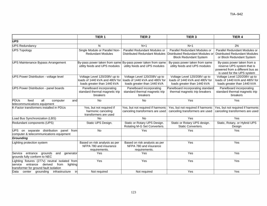
TIA–942
123
TIER 1 TIER 2 TIER 3 TIER 4 UPS UPS Redundancy N N+1 N+1 2N UPS Topology Single Module or Parallel Non-
Redundant Modules Parallel Redundant Modules or Distributed Redundant Modules
Parallel Redundant Modules or Distributed Redundant Modules or
Block Redundant System
Parallel Redundant Modules or Distributed Redundant Modules
or Block Redundant System
UPS Maintenance Bypass Arrangement By-pass power taken from same utility feeds and UPS modules
By-pass power taken from same utility feeds and UPS modules
By-pass power taken from same utility feeds and UPS modules
By-pass power taken from a reserve UPS system that is
powered from a different bus as is used for the UPS system
UPS Power Distribution - voltage level Voltage Level 120/208V up to loads of 1440 kVA and 480V for
loads greater than 1440 kVA
Voltage Level 120/208V up to loads of 1440 kVA and 480V for
loads greater than 1440 kVA
Voltage Level 120/208V up to loads of 1440 kVA and 480V for
loads greater than 1440 kVA
Voltage Level 120/208V up to loads of 1440 kVA and 480V for
loads greater than 1440 kVA UPS Power Distribution - panel boards Panelboard incorporating
standard thermal magnetic trip breakers
Panelboard incorporating standard thermal magnetic trip
breakers
Panelboard incorporating standard thermal magnetic trip breakers
Panelboard incorporating standard thermal magnetic trip
breakers
PDUs feed all computer andtelecommunications equipment
No No Yes Yes
K-Factor transformers installed in PDUs Yes, but not required if harmonic canceling
transformers are used
Yes, but not required if harmonic canceling transformers are used
Yes, but not required if harmonic canceling transformers are used
Yes, but not required if harmonic canceling transformers are used
Load Bus Synchronization (LBS) No No Yes Yes Redundant components (UPS) Static UPS Design. Static or Rotary UPS Design.
Rotating M-G Set Converters. Static or Rotary UPS design.
Static Converters. Static, Rotary, or Hybrid UPS
Design UPS on separate distribution panel fromcomputer & telecommunications equipment
No Yes Yes Yes
Grounding Lighting protection system Based on risk analysis as per
NFPA 780 and insurance requirements.
Based on risk analysis as per NFPA 780 and insurance
requirements.
Yes Yes
Service entrance grounds and generatorgrounds fully conform to NEC
Yes Yes Yes Yes
Lighting fixtures (277v) neutral isolated fromservice entrance derived from lightingtransformer for ground fault isolation
Yes Yes Yes Yes
Data center grounding infrastructure int
Not required Not required Yes Yes

TIA-942
124
computer room
TIER 1 TIER 2 TIER 3 TIER 4 Computer Room Emergency Power Off(EPO) System
Yes
Activated by Emergency Power Off (EPO) atexits with computer and telecommunicationssystem shutdown only
Yes Yes Yes Yes
Automatic fire suppressant release aftercomputer and telecommunications systemshutdown
Yes Yes Yes Yes
Second zone fire alarm system activation withmanual Emergency Power Off (EPO) shutdown
No No No Yes
Master control disconnects batteries andreleases suppressant from a 24/7 attendedstation
No No No Yes
Battery Room Emergency Power Off (EPO)System
Activated by Emergency Power Off (EPO)buttons at exits with manual suppressantrelease
Yes Yes Yes Yes
Fire suppressant release for single zone systemafter Emergency Power Off (EPO) shutdown
Yes Yes Yes Yes
Second zone fire alarm system activation.Disconnects batteries on first zone with suppressant release on the second zone
No No Yes Yes
Master control disconnects batteries andreleases suppressant from a 24/7 attendedstation
No No Yes Yes
Emergency Power Off (EPO) Systems Shutdown of UPS power receptacles in computer room area.
Yes Yes Yes Yes
Shutdown of AC power for CRACs and chillers Yes Yes Yes Yes Compliance with local code (e.g. separatesystems for UPS and HVAC)
Yes Yes Yes Yes

TIA–942
125
TIER 1 TIER 2 TIER 3 TIER 4 System Monitoring Locally Displayed at UPS Yes Yes Yes Yes Central power and environmental monitoringand control system (PEMCS) with remoteengineering console and manual overrides forall automatic controls and set points
No No Yes Yes
Interface with BMS No No Yes Yes Remote Control No No No Yes Automatic Text Messaging to ServiceEngineer's Pager
No No No Yes
Battery Configuration Common Battery String for All Modules Yes No No No One Battery String per Module No Yes Yes Yes Minimum Full Load Standby Time 5 minutes 10 Minutes 15 minutes 15 minutes Battery type Valve regulated lead acid
(VRLA) or flooded type Valve regulated lead acid (VRLA)
or flooded type Valve regulated lead acid (VRLA)
or flooded type Valve regulated lead acid (VRLA)
or flooded type Flooded Type Batteries Mounting Racks or cabinets Racks or cabinets Open racks Open racks Wrapped Plates No Yes Yes Yes Acid Spill Containment Installed Yes Yes Yes Yes Battery Full Load Testing/Inspection Schedule Every two years Every two years Every two years Every two years or annually Battery Room Separate from UPS/Switchgear EquipmentRooms
No Yes Yes Yes
Individual Battery Strings Isolated from EachOther
No Yes Yes Yes
Shatterproof Viewing Glass in Battery RoomDoor
No No No Yes
Battery Disconnects Located Outside Battery Room
Yes Yes Yes Yes
Battery Monitoring System UPS self monitoring UPS self monitoring UPS self monitoring Centralized automated system to check each cell for temperature,
voltage, and impedance

TIA-942
126
TIER 1 TIER 2 TIER 3 TIER 4 Rotating UPS System Enclosures (WithDiesel Generators)
Units Separately Enclosed by Fire Rated Walls No No Yes Yes Fuel Tanks on Exterior No No Yes Yes Fuel Tanks in Same Room as Units Yes Yes No No Standby Generating System Generator Sizing Sized for computer &
telecommunications system electrical & mechanical only
Sized for computer & telecommunications system electrical & mechanical only
Sized for computer & telecommunications system
electrical & mechanical only + 1 spare
Total Building Load + 1 Spare
Generators on Single Bus Yes Yes Yes No Single Generator per System with (1) SpareGenerator
No Yes Yes Yes
Individual 83 ft. Ground Fault Protection forEach Generator
No Yes Yes Yes
Loadbank for Testing Testing UPS modules only Yes Yes Yes No Testing of Generators only Yes Yes Yes No Testing of Both UPS modules and generators No No No Yes UPS Switchgear No No No Yes Permanently Installed No - Rental No - Rental No - Rental Yes Equipment Maintenance Maintenance Staff Onsite Day Shift only. On-call at
other times Onsite Day Shift only. On-call at
other times Onsite 24 hrs M-F, on-call on
weekends Onsite 24/7
Preventative Maintenance None None Limited preventative maintenance program
Comprehensive preventative maintenance program
Facility Training Programs None None Comprehensive training program Comprehensive training program including manual operation
procedures if it is necessary to bypass control system
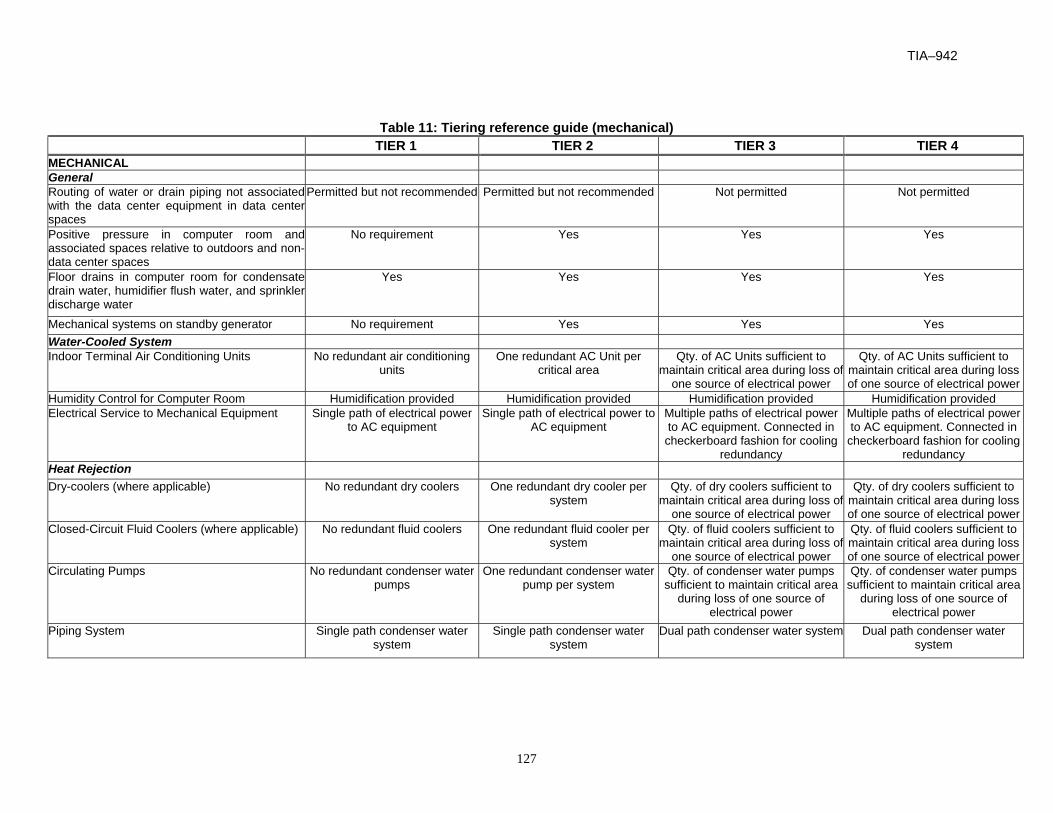
TIA–942
127
Table 11: Tiering reference guide (mechanical) TIER 1 TIER 2 TIER 3 TIER 4 MECHANICAL General Routing of water or drain piping not associatedwith the data center equipment in data centerspaces
Permitted but not recommended Permitted but not recommended Not permitted Not permitted
Positive pressure in computer room andassociated spaces relative to outdoors and non-data center spaces
No requirement Yes Yes Yes
Floor drains in computer room for condensatedrain water, humidifier flush water, and sprinklerdischarge water
Yes Yes Yes Yes
Mechanical systems on standby generator No requirement Yes Yes Yes Water-Cooled System Indoor Terminal Air Conditioning Units No redundant air conditioning
units One redundant AC Unit per
critical area Qty. of AC Units sufficient to
maintain critical area during loss of one source of electrical power
Qty. of AC Units sufficient to maintain critical area during loss of one source of electrical power
Humidity Control for Computer Room Humidification provided Humidification provided Humidification provided Humidification provided Electrical Service to Mechanical Equipment Single path of electrical power
to AC equipment Single path of electrical power to
AC equipment Multiple paths of electrical power to AC equipment. Connected in checkerboard fashion for cooling
redundancy
Multiple paths of electrical power to AC equipment. Connected in
checkerboard fashion for cooling redundancy
Heat Rejection Dry-coolers (where applicable) No redundant dry coolers One redundant dry cooler per
system Qty. of dry coolers sufficient to
maintain critical area during loss of one source of electrical power
Qty. of dry coolers sufficient to maintain critical area during loss of one source of electrical power
Closed-Circuit Fluid Coolers (where applicable) No redundant fluid coolers One redundant fluid cooler per system
Qty. of fluid coolers sufficient to maintain critical area during loss of
one source of electrical power
Qty. of fluid coolers sufficient to maintain critical area during loss of one source of electrical power
Circulating Pumps No redundant condenser water pumps
One redundant condenser water pump per system
Qty. of condenser water pumps sufficient to maintain critical area
during loss of one source of electrical power
Qty. of condenser water pumps sufficient to maintain critical area
during loss of one source of electrical power
Piping System Single path condenser water system
Single path condenser water system
Dual path condenser water system Dual path condenser water system

TIA-942
128
TIER 1 TIER 2 TIER 3 TIER 4 Chilled Water System Indoor Terminal Air Conditioning Units No redundant air conditioning
units One redundant AC Unit per
critical area Qty. of AC Units sufficient to
maintain critical area during loss of one source of electrical power
Qty. of AC Units sufficient to maintain critical area during loss of one source of electrical power
Humidity Control for Computer Room Humidification provided Humidification provided Humidification provided Humidification provided Electrical Service to Mechanical Equipment Single path of electrical power
to AC equipment Single path of electrical power to
AC equipment Multiple paths of electrical power
to AC equipment Multiple paths of electrical power
to AC equipment Heat Rejection Chilled Water Piping System Single path chilled water system Single path chilled water system Dual path chilled water system Dual path chilled water system Chilled Water Pumps No redundant chilled water
pumps One redundant chilled water
pump per system Qty. of chilled water pumps
sufficient to maintain critical area during loss of one source of
electrical power
Qty. of chilled water pumps sufficient to maintain critical area
during loss of one source of electrical power
Air-Cooled Chillers No redundant chiller One redundant chiller per system Qty. of chilled water pumps sufficient to maintain critical area
during loss of one source of electrical power
Qty. of chillers sufficient to maintain critical area during loss of one source of electrical power
Water-cooled Chillers No redundant chiller One redundant chiller per system Qty. of chillers sufficient to maintain critical area during loss of
one source of electrical power
Qty. of chillers sufficient to maintain critical area during loss of one source of electrical power
Cooling Towers No redundant cooling tower One redundant cooling tower per system
Qty. of cooling towers sufficient to maintain critical area during loss of
one source of electrical power
Qty. of cooling towers sufficient to maintain critical area during loss of one source of electrical
power Condenser Water Pumps No redundant condenser water
pumps One redundant condenser water
pump per system Qty. of condenser water pumps
sufficient to maintain critical area during loss of one source of
electrical power
Qty. of condenser water pumps sufficient to maintain critical area
during loss of one source of electrical power
Condenser Water Piping System Single path condenser water system
Single path condenser water system
Dual path condenser water system Dual path condenser water system

TIA–942
129
TIER 1 TIER 2 TIER 3 TIER 4 Air-Cooled System Indoor Terminal Air Conditioning Units/OutdoorCondensers
No redundant air conditioning units
One redundant AC Unit per critical area
Qty. of AC Units sufficient to maintain critical area during loss of
one source of electrical power
Qty. of AC Units sufficient to maintain critical area during loss of one source of electrical power
Electrical Service to Mechanical Equipment Single path of electrical power to AC equipment
Single path of electrical power to AC equipment
Multiple paths of electrical power to AC equipment
Multiple paths of electrical power to AC equipment
Humidity Control for Computer Room Humidification provided Humidification provided Humidification provided Humidification provided HVAC Control System HVAC Control System Control system failure will
interrupt cooling to critical areasControl system failure will not
interrupt cooling to critical areas Control system failure will not
interrupt cooling to critical areas Control system failure will not
interrupt cooling to critical areas Power Source to HVAC Control System Single path of electrical power
to HVAC control system Redundant, UPS electrical power
to AC equipment Redundant, UPS electrical power
to AC equipment Redundant, UPS electrical power
to AC equipment Plumbing (for water-cooled heat rejection) Dual Sources of Make-up Water Single water supply, with no on-
site back-up storage Dual sources of water, or one
source + on-site storage Dual sources of water, or one
source + on-site storage Dual sources of water, or one
source + on-site storage Points of Connection to Condenser WaterSystem
Single point of connection Single point of connection Two points of connection Two points of connection
Fuel Oil System Bulk Storage Tanks Single storage tank Multiple storage tanks Multiple storage tanks Multiple storage tanks Storage Tank Pumps and Piping Single pump and/or supply pipe Multiple pumps, multiple supply
pipes Multiple pumps, multiple supply
pipes Multiple pumps, multiple supply
pipes
Fire Suppression Fire detection system no yes yes yes Fire sprinkler system When required Pre-action (when required) Pre-action (when required) Pre-action (when required) Gaseous suppression system no no clean agents listed in NFPA 2001 clean agents listed in NFPA 2001 Early Warning Smoke Detection System no yes yes yes Water Leak Detection System no yes yes yes

TIA-942
[This page is intentionally left blank]
130

TIA–942
131
ANNEX H (INFORMATIVE) DATA CENTER DESIGN EXAMPLES
This annex is informative only and is not part of this Standard.
H.1 Small data center design example
One example layout for a small data center is shown below. This is an example of a data center that is small enough to be supported by a main distribution area and no horizontal distribution areas.
Figure 20: Computer room layout showing “hot” and “cold” aisles
This computer room space is about 1,920 square feet. It has 73 server cabinets in the equipment distribution areas (EDAs) and six 19” racks in the main distribution area (MDA). The six MDA racks are the six ‘SWITCH AND PATCHING RACKS’ at the bottom of the drawing. It was not necessary to put the MDA in the center of the computer room because distance limitations were not an issue. However, cable lengths and cable congestion in the aisles perpendicular to the cabinet aisles could have been reduced by placing the MDA in the center of the room instead.
The MDA supports the HC for horizontal cabling to the EDAs. In a data center with a high density of cabling to the equipment cabinets, it would probably be necessary to have horizontal distribution areas (HDAs) to minimize cable congestion near the MDA.
The rack and cabinet rows are parallel to the direction of under floor airflow created by the Computer Room Air Conditioning (CRAC) units. Each CRAC is located facing the “hot” aisles to allow more efficient return air to each CRAC unit.
Server cabinets are arranged to form alternating “hot” and “cold” aisles
Communications cables are run in wire trays (baskets) in the “hot” aisle area. Power cables are run under the access floor in the “cold” aisles.

TIA-942
132
The computer room is separate from the Network Operations Center (NOC is not shown) for access and contaminant control.
H.2 Corporate data center design example
The following example is for an internet or web hosting data center used to house computer and telecommunications equipment for multiple corporate web sites.
The corporate data center in this example has two floors of about 4,140 sq m (44,500 sq ft) each. This data center is an example of a data center with several horizontal distribution areas, each differentiated primarily by the type of systems that they support. Due to the density of cabling to the personal computer based servers, these systems are served by two horizontal distribution areas (HDAs), each supporting only 24 server cabinets. Seven additional horizontal distribution areas are planned to support additional server cabinets. Thus, horizontal distribution areas may be required not only for different functional areas, but also to minimize cable congestion in the HDA. Each HDA was designed to support a maximum of 2,000 4-pair category 6 cables.
The 1st floor includes the electrical rooms, mechanical rooms, storage rooms, loading dock, security room, reception area, operations center, and entrance room.
The computer room is on the 2nd floor and is entirely on access floor. All telecommunications cabling is run under the access floor space in wire-basket cable trays. In some locations where the volume of cables is the greatest and where they do not impede airflow, the cable trays are installed in two layers. The drawing below shows the 2nd floor computer room with cable trays.
MDA
MainframeHDA
TapeHDA
MinicomputerHDA
SANHDA
WSHDA
InternetHDA
PC2HDA
PC1HDA
Figure 21: Example for corporate data center

TIA–942
133
Telecommunications cabling is installed in the “hot” aisles behind the server cabinets. Electrical cabling is installed in the “cold” aisles in front of the server cabinets. Both telecommunications cabling and electrical cabling follow the main aisles in the east/west direction, but follow separate pathways to maintain separation of power and telecommunications cabling.
The locations of the Entrance Room on the 1st floor and MDA on the 2nd floor are carefully positioned so that T-1 and T-3 circuits can be terminated on equipment anywhere in the computer room.
Cabinets for rack-mounted servers have standardized cabling that includes multimode fiber and category 6 UTP. Administration is somewhat simplified if cabinets have a standard cabling configuration.
In this data center, due to the very wide variety of cabling requirements for floor standing systems, it was not possible to develop a standardized configuration for zone outlets.
H.3 Internet data center design example
The internet data center in this example has one floor of approximately 9,500 sq m (102,000 sq ft) with a computer room of about 6400 sq m (69,000 sq ft). It is an example of a data center where horizontal distribution areas are differentiated primarily by the area served rather than the type of systems that they support. The drawing below shows the data center floor plan with cable trays. MDA and HDA racks are shown but customer racks and cabinets are not.
A/C
A/C
A/C
A/C
A/C
A/C
A/C
A/C
A/CA/C
A/C
A/C
A/CA/C
A/C
A/C
A/C
A/C
A/C
MEN
WO
MEN
M JAN
OFFOFF
SHIPPING/RECEIVING
W
STORAGE 2
STORAGE 1
STAGING
A/C
A/C
A/C
A/C
A/C
SAN
OFFICE
ROOM
DINING
W/C
OFFICEOFFICEOFFICE
AISLE
OFFICE
COURTYARD
OPEN OFFIC
EO
FFICE
OFFIC
E
KITCHEN
CO
NFER
ENC
ERO
OM
SERVERY
OPEN
OFFIC
EC
ON
FEREN
CE
OFFIC
EO
FFICE
JAN.
AISLE
SEC.
CONFERENCE
W/C
OFFICEOFFICE
OFFICE
PATIO
COURTYARD
INTERIOR
OPEN
OFFIC
E
ROO
M
CO
RR
IDO
R
AISLE
CORRIDORLOBBY
HDA1 HDA4
HDA2
HDA6HDA3
TR MDAHDA5
Figure 22: Example for internet data center
TIA-942
134
The main distribution area (MDA) incorporates the function of the entrance room and the main cross-connect. It accommodates 50 access provider racks and 20 racks for the main cross-connect space. This room is supported by two dedicated PDUs, two dedicated computer room air conditioning units, and is on access floor. The MDA is in a dedicated room with a separate entrance that allows access and service providers to work in this room without entering the customer spaces in the main computer room. The locations of the MDA and HDAs were planned to ensure that circuit lengths for T-1 and T-3 circuits will not be exceeded for circuits to any rack in the computer room.
Automated tape libraries, storage servers, and control equipment for storage services are in a dedicated SAN room adjacent to the MDA. This equipment is provided and managed by third parties, not by the owner of the internet data center. A separate room for this equipment allows storage service providers to manage their equipment without entering the main computer room.
The computer room space has 4,300 customer racks. The customer space is supported by six horizontal distribution areas (HDAs) to limit the volume of cable in the underfloor cable trays. Each HDA supports approximately 2,000 copper-pair connections. These HDAs are in the center of the spaces they serve to minimize cable lengths. Cabling from the HDAs to the customer racks is standardized to simplify administration. However, additional cabling may be run to customer racks as required.
Telecommunications cabling to storage and staging areas east of the computer room are supported from the MDA. Telecommunications cabling for the offices west of the computer room are supported by a telecommunications room (TR).

TIA–942
135
ANNEX I (INFORMATIVE) BIBLIOGRAPHY AND REFERENCES
This annex is informative only and is not part of this Standard.
This annex contains information on the documents that are related to or have been referenced in
this document. Many of the documents are in print and are distributed and maintained by national
or international standards organizations. These documents can be obtained through contact with
the associated standards body or designated representatives. The applicable electrical code in
the United States is the National Electrical Code.
• ANSI/IEEE C2-1997, National Electrical Safety Code
• ANSI/NFPA 70-2002, National Electrical Code
• ANSI/NFPA 75-2003, Standard for the protection of information technology equipment
• ANSI T1.336, Engineering requirements for a universal telecommunications frame.
• ANSI/TIA/EIA-568-B.1-2001, Commercial Building Telecommunications Cabling Standard
• ANSI/TIA/EIA-568-B.2-2001, Commercial Building Telecommunications Cabling Standard:
Part 2: Balanced Twisted-Pair Cabling Components.
• ANSI/TIA/EIA-568-B.3-2000, Optical Fiber Cabling Components
• ANSI/TIA-569-A-1998, Commercial Building Standard for Telecommunications Pathways and
Spaces
• ANSI/TIA/EIA-606-A-2002, Administration Standard for the Telecommunications
Infrastructure of Commercial Buildings
• ANSI/TIA/EIA-J-STD-607-2001, Commercial Building Grounding (Earthing) and Bonding
Requirements for Telecommunications
• ANSI/TIA-758-1999, Customer-owned Outside Plant Telecommunications Cabling Standard
• ASHRAE, Thermal Guidelines for Data Processing Environments
• ASTM B539-90, Measuring Contact Resistance of Electrical Connections (Static Contacts)
• BICSI Telecommunications Distribution Methods Manual
• BICSI Cabling Installation Manual
• BICSI Customer-owned Outside Plant Methods Manual
• BOMA – Building Owners Management Association, International – Codes & Issues, July
2000
• CABA - Continental Automated Buildings Association,
• Federal Communications Commission (FCC) Washington D.C., "The Code of Federal
Regulations, FCC 47 CFR 68"
• Federal Telecommunications Recommendation 1090-1997, Commercial Building
Telecommunications Cabling Standard, by National Communications System (NCS)

TIA-942
136
• IBC, International Building Code
• ICC, International Code Council
• IEEE Std. 142, Recommended Practice for Grounding of Industrial and Commercial Power
Systems
• IEEE Std. 446, Recommended Practice for Emergency and Standby Power Systems for
Industrial and Commercial Applications
• IEEE Std. 1100, Recommended Practice for Powering and Grounding Electronic Equipment
• IEEE 802.3-2002 (also known as ANSI/IEEE Std 802.3-2002 or ISO 8802-3: 2002 (E),
Carrier Sense Multiple Access with Collision Detection (CSMA/CD) Access Method and
Physical Layer Specifications
• IEEE 802.4-1990, Standard for Local Area Network Token Passing Bus Access Method,
Physical Layer Specification
• IEEE 802.5-1998, Token Ring Access Method and Physical Layer Specifications
• IEEE 802.7-1989 (R1997) IEEE Recommended Practices for Broadband Local Area
Networks (ANSI)
• IEEE Standard 518-1982, Guide for the installation of electrical equipment to minimize
electrical noise to controllers of external sources
• IFMA – International Facility Management Association - Ergonomics for Facility Managers,
June 2000
• NFPA 72,National Fire Alarm Code, 1999
• NFPA 2001, Standard on clean agent fire extinguishing systems, 2000 Edition
• NEC, National Electrical Code, article 725, Class 1, Class 2 and Class 3 Remote-Control,
Signaling and Power-Limited Circuits.
• NEC, National Electrical Code, article 760, Fire Alarm System.
• NEMA VE 2-2001, cable tray installation guidelines
• Society of Cable Television Engineers, Inc., Document #IPS-SP-001, Flexible RF Coaxial
Drop cable Specification
• TIA/EIA TSB-31-B, FCC 47 CFR 68, Rationale and Measurement Guidelines
• ANSI/TIA/EIA-485-A-1998, Electrical Characteristics of Generators and Receivers for Use in
Balanced Digital Multipoint Systems
• TIA/EIA-TSB89-1998, Application Guidelines for TIA/EIA-485-A
• UL 444/CSA-C22.2 No. 214-94, Communications Cables
• The Uptime Institute White Paper, Alternating Cold and Hot Aisles Provides More Reliable
Cooling for Server Farms
• The Uptime Institute White Paper, Industry Standard Tier Classifications Define Site
Infrastructure Performance

TIA–942
137
• The Uptime Institute White Paper, Fault-Tolerant Power Compliance Specification
TIA-942
138
The organizations listed below can be contacted to obtain reference information.
ANSI
American National Standards Institute (ANSI)
11 W 42 St.
New York, NY 10032
USA
(212) 642-4900
www.ansi.org
American Society of Heating, Refrigeration and Air conditioning Engineers (ASHRAE)
1791 Tullie Circle, NE
Atlanta, GA 30329
1-800-527-4723
(404) 636-8400
www.ashrae.org
ASTM
American Society for Testing and Materials (ASTM)
100 Barr Harbor Drive
West Conshohocken, PA 19428-2959
USA
(610) 832-9500
www.astm.org
BICSI
Building Industry Consulting Service International (BICSI)
8610 Hidden River Parkway
Tampa, FL 33637-1000
USA
(800) 242-7405
www.bicsi.org
TIA–942
139
CSA
Canadian Standards Association International (CSA)
178 Rexdale Blvd.
Etobicoke, (Toronto), Ontario
Canada M9W 1R3
(416) 747-4000
www.csa-international.org
EIA
Electronic Industries Alliance (EIA)
2500 Wilson Blvd., Suite 400
Arlington, VA 22201-3836
USA
(703) 907-7500
www.eia.org
FCC
Federal Communications Commission (FCC)
Washington, DC 20554
USA
(301) 725-1585
www.fcc.org
Federal and Military Specifications
National Communications System (NCS)
Technology and Standards Division
701 South Court House Road Arlington, VA 22204-2198
USA
(703) 607-6200
www.ncs.gov
International Code Council (ICC)
International Building Code (IBC)
5203 Leesburg Pike, Suite 600
Falls Church, VA 22041
703-931-4533
www.iccsafe.org

TIA-942
140
IEC
International Electrotechnical Commission (IEC)
Sales Department
PO Box 131
3 rue de Varembe
1211 Geneva 20
Switzerland
+41 22 919 02 11
www.iec.ch
IEEE
The Institute of Electrical and Electronic Engineers, Inc (IEEE)
IEEE Service Center
445 Hoes Ln., PO Box 1331
Piscataway, NJ 08855-1331
USA
(732) 981-0060
www.ieee.org
IPC
The Institute for Interconnecting and Packaging Electronic Circuits
2215 Sanders Rd.
Northbrook, IL 60062-6135
USA
(847) 509-9700
www.ipc.org

TIA–942
141
ISO
International Organization for Standardization (ISO)
1, Rue de Varembe
Case Postale 56
CH-1211 Geneva 20
Switzerland
+41 22 74 901 11
www.iso.ch
NEMA
National Electrical Manufacturers Association (NEMA)
1300 N. 17th Street, Suite 1847
Rosslyn, VA 22209
USA
(703) 841-3200
www.nema.org
NFPA
National Fire Protection Association (NFPA)
Batterymarch Park
Quincy, MA 02269-9101
USA
(617) 770-3000
www.nfpa.org
SCTE
Society of Cable Telecommunications Engineers (SCTE)
140 Philips Rd.
Exton, PA 19341-1318
USA
(800) 542-5040
www.scte.org
TIA-942
142
Telcordia Technologies (formerly; Bellcore)
Telcordia Technologies Customer Service
8 Corporate Place Room 3C-183
Piscataway, NJ 08854-4157
USA
(800) 521-2673
www.telcordia.com
The Uptime Institute, Inc.
1347 Tano Ridge Road
Santa Fe, NM 87506
USA
(505) 986-3900
www.upsite.com
TIA
Telecommunications Industry Association (TIA)
2500 Wilson Blvd., Suite 300
Arlington, VA 22201-3836
USA
(703) 907-7700
www.tiaonline.org
UL
Underwriters Laboratories, Inc. (UL)
333 Pfingsten Road
Northbrook, IL 60062-2096
USA
(847) 272-8800
www.ul.com