Embed Size (px)
Citation preview
This material exempt per Department of Commerce license exception TSU
EDK Introduction
EDK Intro 2
Objectives
After completing this module, you will be able to:• Describe the embedded systems development flow• Understand the components in the hardware design • Specify ways to create a hardware design• Identify the tools included in EDK • Locate the EDK documentation
EDK Intro 3
Outline
• Introduction• EDK
– Overview of EDK– Embedded Development Design
Flow– XPS Platform Management
• Supported Platforms• Appendix: Project Files and
Structures
EDK Intro 4
Embedded Systems
• An embedded system is nearly any computing system (other than a general-purpose computer) with the following characteristics– Single-functioned
• Typically, is designed to perform predefined function
– Tightly constrained• Tuned for low cost • Single-to-fewer components based • Performs functions fast enough• Consumes minimum power
– Reactive and real-time• Must continually monitor the desired environment and react to changes
– Hardware and software co-existence
EDK Intro 5
Embedded Systems
• Examples:– Mobile phone systems
• Customer handsets and base stations– Communication devices
• Wired and wireless routers and switches– Automotive applications
• Braking systems, traction control, airbag release systems, and cruise-control applications
– Aerospace applications• Flight-control systems, engine controllers, auto-pilots and passenger in-flight
entertainment systems– Defense systems
• Radar systems, fighter aircraft flight-control systems, radio systems, and missile guidance systems
EDK Intro 6
Current Technologies
• Microcontroller-based systems• DSP processor-based systems• ASIC technology• FPGA technology
EDK Intro 7
Embedded Software Tools
CPU
Logic Design Tools
I/O
FPGA
Memory
Logic Design Tools
FPGA + Memory + IP +High Speed IO
(4K & Virtex)
Embedded Software Tools
CPU
Inte
grat
ion
of F
unct
ions
Inte
grat
ion
of F
unct
ions
TimeTime
Logic Design Tools
Embedded Software Tools
Logic + Memory + IP +
Processors + RocketIO
(Virtex-II Pro)
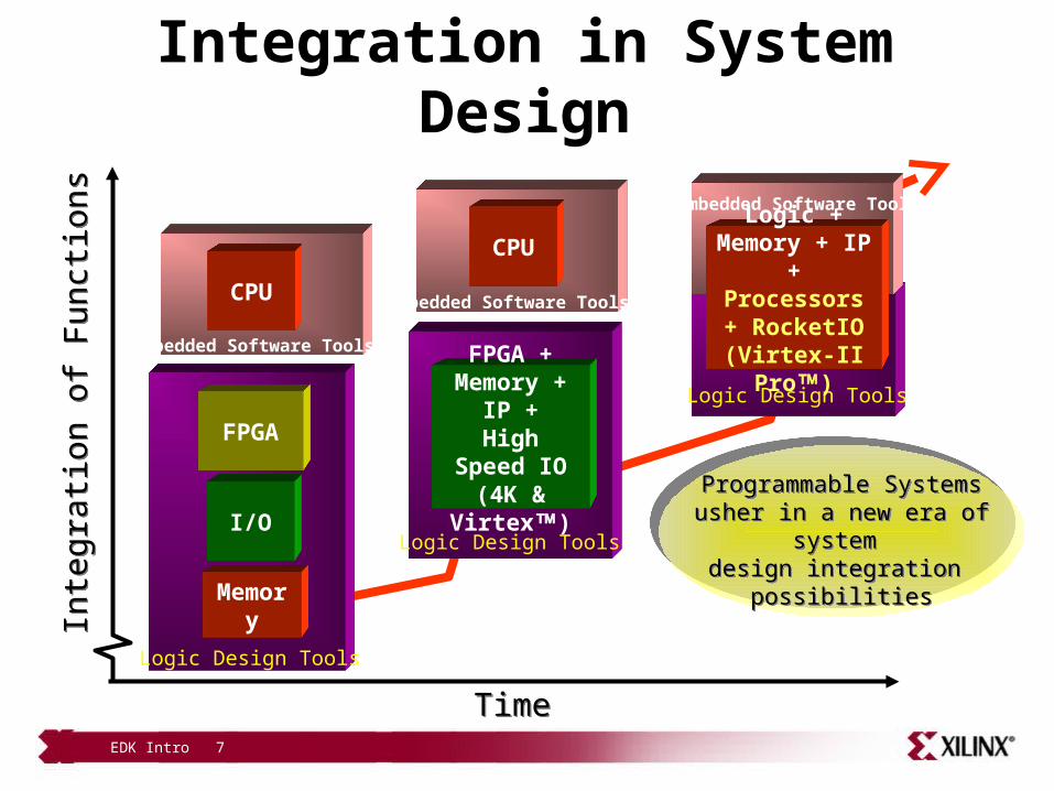
Programmable Systemsusher in a new era of system
design integration possibilities
Programmable Systemsusher in a new era of system
design integration possibilities
Integration in System Design
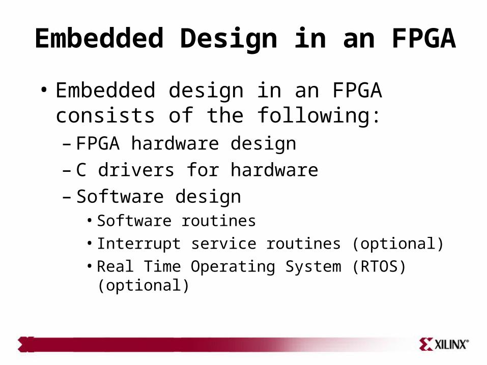
Embedded Design in an FPGA
• Embedded design in an FPGA consists of the following:– FPGA hardware design– C drivers for hardware– Software design
• Software routines• Interrupt service routines (optional)• Real Time Operating System (RTOS) (optional)
EDK Intro 9
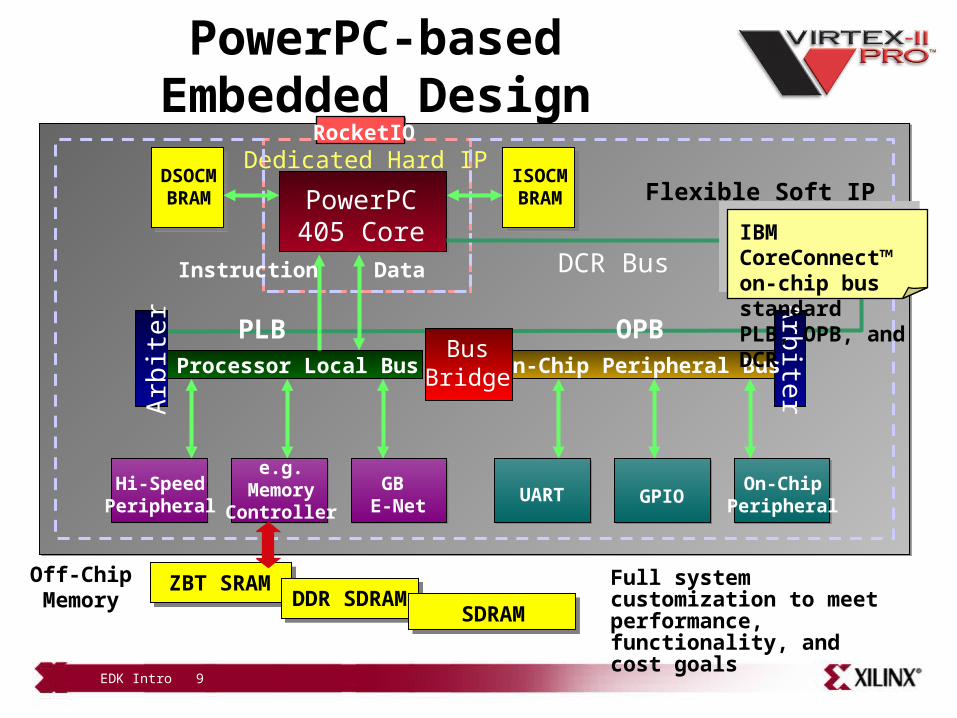
PowerPC405 Core
Dedicated Hard IPFlexible Soft IP
RocketIO
PowerPC-based Embedded Design
Full system customization to meet
performance, functionality, and cost goals
DCR Bus
UART GPIOOn-Chip
PeripheralHi-Speed
PeripheralGB
E-Net
e.g.Memory
Controller
Arb
iter
On-Chip Peripheral Bus
OPB
Arb
iter
Processor Local Bus
Instruction Data
PLB
DSOCMBRAM
ISOCMBRAM
Off-ChipMemory
ZBT SRAMDDR SDRAM
SDRAM
BusBridge
IBM CoreConnect™on-chip bus standardPLB, OPB, and DCR

EDK Intro 10
MicroBlaze Processor-Based Embedded Design
Flexible Soft IPMicroBlaze32-Bit RISC Core
UART 10/100E-Net
Memory Controller
Off-ChipMemory
FLASH/SRAM
Fast Simplex Link
0,1….7
CustomFunctions
CustomFunctions
BRAM Local Memory
BusD-CacheBRAM
I-CacheBRAM
ConfigurableSizes
Arb
iter
Processor Local Bus
Instruction Data
PLBBus
Bridge
PowerPC405 Core
Dedicated Hard IP
Arb
iter
Processor Local Bus
Instruction Data
PLBBus
BridgeBus
Bridge
PowerPC405 Core
Dedicated Hard IP
PowerPC405 Core
Dedicated Hard IP
PowerPC405 Core
Dedicated Hard IPPossible inVirtex-II Pro
Hi-SpeedPeripheral
GB E-Net
e.g.Memory
Controller
Hi-SpeedPeripheralHi-Speed
PeripheralGB
E-NetGB
E-Net
e.g.Memory
Controller
e.g.Memory
Controller
Arb
iter OPB
On-Chip Peripheral Bus
CacheLink
SRAM
EDK Intro 11
Outline
• Introduction• EDK
– Overview of EDK– Embedded Development Design
Flow– XPS Platform Management Hardware
Design
• Supported Platforms• Appendix: Project Files and
Structures
EDK Intro 12
Embedded Development Kit
• What is Embedded Development Kit (EDK)?
– The Embedded Development Kit is the Xilinx software suite for designing complete embedded programmable systems
– The kit includes all the tools, documentation, and IP that you require for designing systems with embedded IBM PowerPC™ hard processor cores, and/or Xilinx MicroBlaze™ soft processor cores
– It enables the integration of both hardware and software components of an embedded system
EDK Intro 13
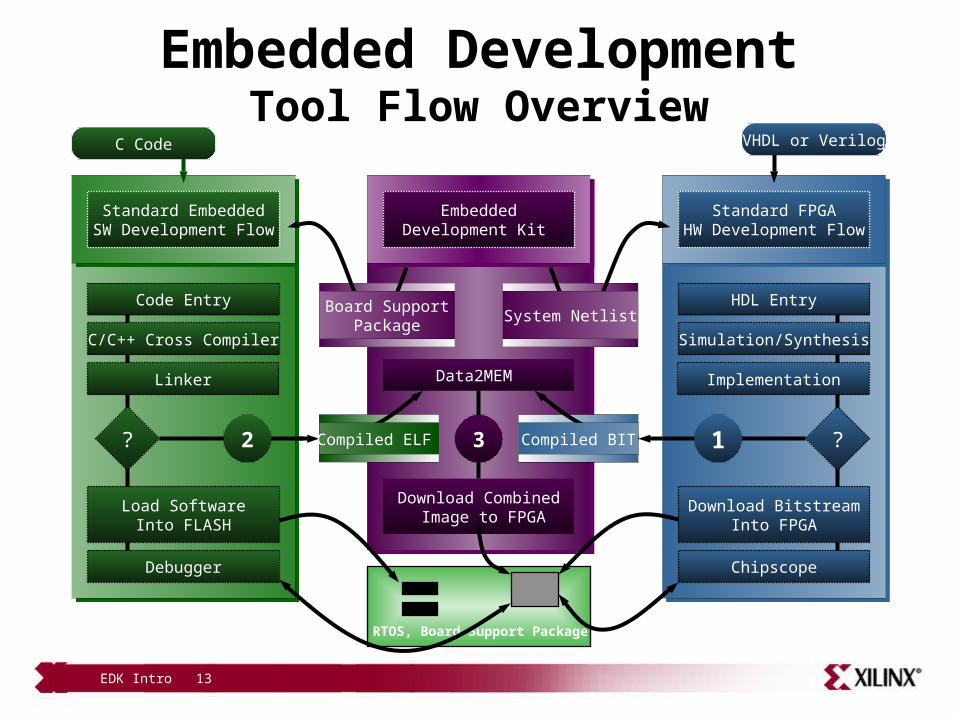
Embedded DevelopmentTool Flow Overview
Data2MEM
Download Combined Image to FPGA
Compiled ELF Compiled BIT
RTOS, Board Support Package
EmbeddedDevelopment Kit
Instantiate the ‘System Netlist’ and Implement
the FPGA
?
HDL Entry
Simulation/Synthesis
Implementation
Download BitstreamInto FPGA
Chipscope
Standard FPGAHW Development Flow
VHDL or Verilog
System NetlistInclude the BSPand Compile theSoftware Image
?
Code Entry
C/C++ Cross Compiler
Linker
Load SoftwareInto FLASH
Debugger
Standard EmbeddedSW Development Flow
C Code
Board SupportPackage
12 3 Compiled BITCompiled ELF

EDK Intro 14
Embedded System Tools• GNU software development tools
– C/C++ compiler for the MicroBlaze™ and PowerPC™ processors (gcc)– Debugger for the MicroBlaze and PowerPC processors (gdb)
• Hardware and software development tools– Base System Builder Wizard– Hardware netlist generation tool: PlatGen– Software Library generation tool: LibGen– Simulation model generation tool: SimGen– Create/Import Peripherals Wizard– Xilinx Microprocessor Debug (XMD)– Hardware debugging using ChipScope™ Pro Analyzer cores– Eclipse IDE-based Software Development Kit (SDK)– Application code profiling tools– Virtual Platform generator: VPGen– Flash Writer utility
EDK Intro 15
Embedded System Tools
• Board Support Packages (BSPs)– Standalone BSP– Wind River VxWorks– MontaVista Linux– Xilinx MicroKernel (XMK)
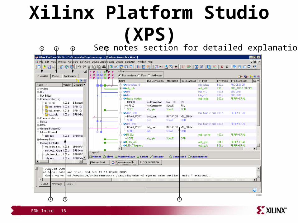
• Xilinx Platform Studio– Xilinx Platform Studio (XPS) is a graphical Integrated Design
Environment (IDE) that incorporates all the Embedded System Tools for seamless creation of hardware and software components and, optionally, a verification component
EDK Intro 16
Xilinx Platform Studio (XPS)See notes section for detailed explanation
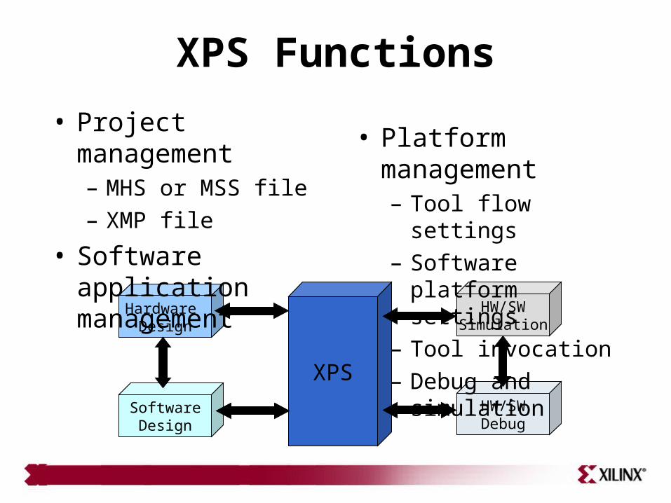
XPS Functions
XPS
HW/SWSimulation
HW/SWDebug
Hardware Design
SoftwareDesign
• Project management– MHS or MSS file– XMP file
• Software application management
• Platform management– Tool flow settings– Software platform settings– Tool invocation– Debug and simulation
EDK Intro 18
Outline
• Introduction• EDK
– Overview of EDK– Embedded Development Design
Flow– XPS Platform Management
• Supported Platforms• Appendix: Project Files and
Structures
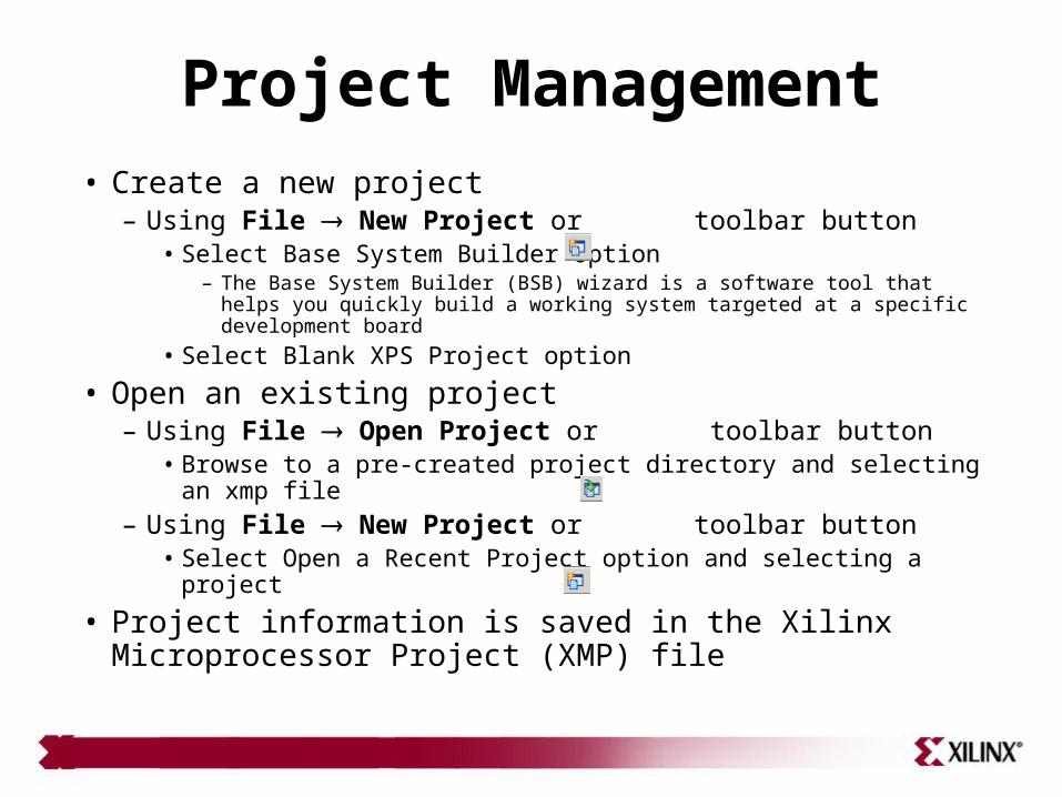
Project Management
• Create a new project– Using File New Project or toolbar button
• Select Base System Builder option– The Base System Builder (BSB) wizard is a software tool that helps you quickly build
a working system targeted at a specific development board• Select Blank XPS Project option
• Open an existing project– Using File Open Project or toolbar button
• Browse to a pre-created project directory and selecting an xmp file– Using File New Project or toolbar button
• Select Open a Recent Project option and selecting a project
• Project information is saved in the Xilinx Microprocessor Project (XMP) file
EDK Intro 20
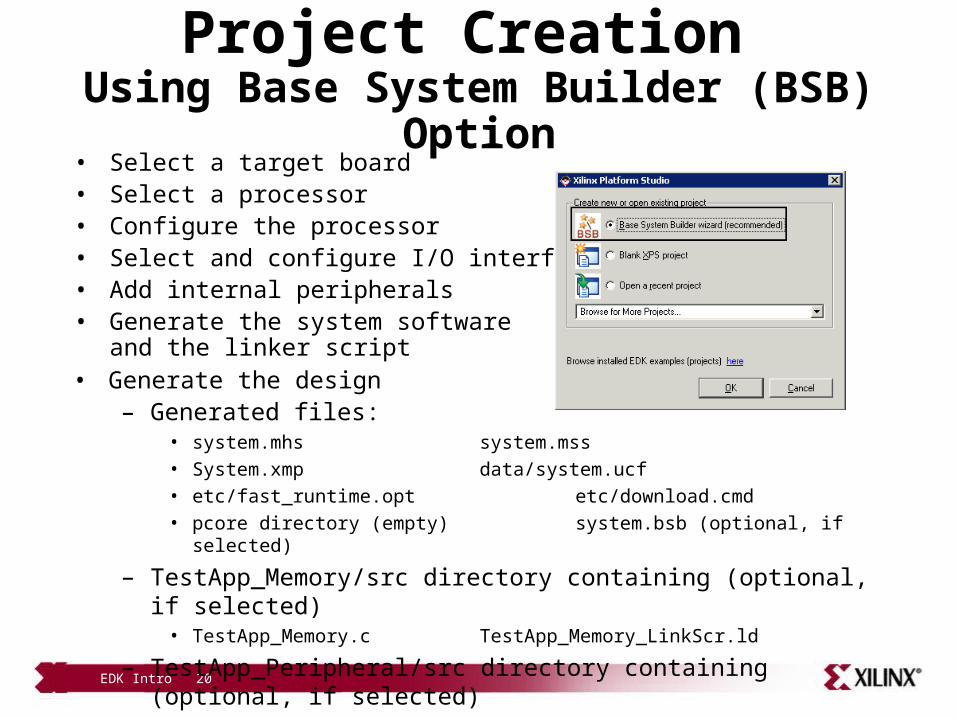
Project Creation Using Base System Builder (BSB) Option• Select a target board• Select a processor• Configure the processor• Select and configure I/O interfaces• Add internal peripherals• Generate the system software
and the linker script• Generate the design
– Generated files:• system.mhs system.mss• System.xmp data/system.ucf• etc/fast_runtime.opt etc/download.cmd• pcore directory (empty) system.bsb (optional, if selected)
– TestApp_Memory/src directory containing (optional, if selected)• TestApp_Memory.c TestApp_Memory_LinkScr.ld
– TestApp_Peripheral/src directory containing (optional, if selected)• TestApp_Peripheral TestApp_Peripheral/src/TestApp_Periperal_LinkScr.ld
EDK Intro 21
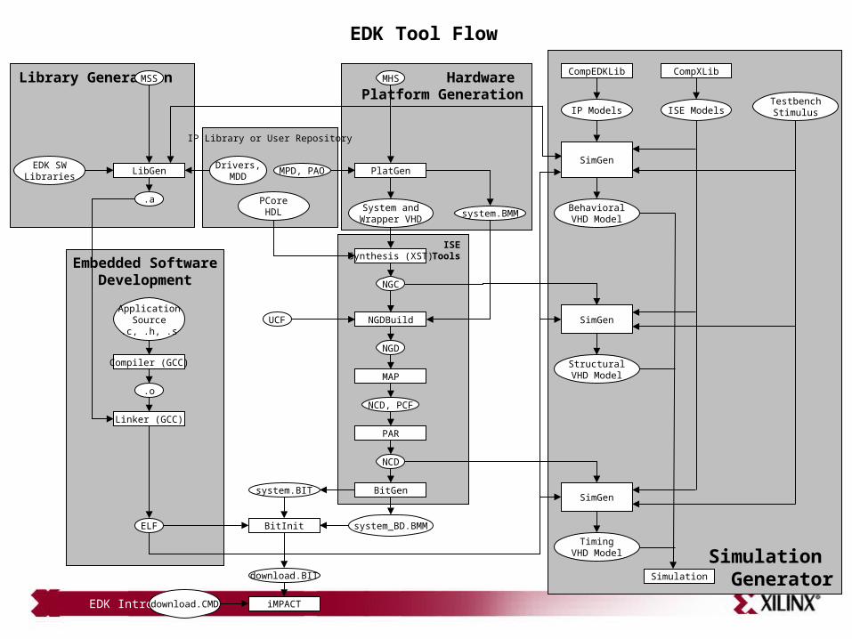
Simulation Generator
Hardware Platform Generation
Library Generation
Embedded SoftwareDevelopment
ISETools
IP Library or User Repository
MSS
LibGen
.a
Compiler (GCC)
.o
Linker (GCC)
ELF
MHS
PlatGenDrivers,
MDDMPD, PAO
PCoreHDL System and
Wrapper VHDsystem.BMM
Synthesis (XST)
NGC
NGDBuildUCF
NGD
MAP
NCD, PCF
PAR
NCD
BitGensystem.BIT
BitInit
download.BIT
iMPACT
system_BD.BMM
SimGen
BehavioralVHD Model
SimGen
StructuralVHD Model
SimGen
TimingVHD Model
Simulation
IP Models ISE ModelsTestbenchStimulus
CompEDKLib CompXLib
ApplicationSource.c, .h, .s
EDK Tool Flow
download.CMD
EDK SWLibraries
EDK Intro 22
Hardware Implementation XPS/Xflow
• Xflow – Implement hardware and generate the bitstream– Input files → .ngc netlists, .bmm file, system.vhd, .ucf– Output Files → system.bit, system_bd.bmm– Xflow calls the ISE™ Implementation tools using
fast_runtime.opt file • NGDBuild, MAP, PAR, and TRACE are executed
– Xflow then calls the BitGen program using bitgen.ut file• BitGen generates the bit file system.bit • BitGen also generates the back-annotated system_bd.bmm BMM file,
which contains the physical location of the block RAMs
EDK Intro 23
Hardware Implementation ISE/XPS Flow
• The ISE/XPS flow provides integration of a processor system at two levels as a component in a FPGA design :
– The processor system is the top-level design– The processor system is a submodule
• Once the processor system is added in the ISE project, XPS can be invoked from ISE by selecting xmp file in Sources window and double-clicking Manage Processor System in the Processes window
• Add user constraint file in ISE• Implement design in ISE by selecting top-level module in Sources window and double-
clicking Implement Design in Processes window• Executable software can be merged by selecting top-level module in Sources window
and double-clicking Update Bitstream with Processor Data in Processes window– This will call XPS in background to update the bitstream and generate system.bit and download.bit files in
implementation directory as well as copy the file as system_stub.bit and system_stub_download.bit files in the ISE project directory
EDK Intro 24
Software Flow Library Generation
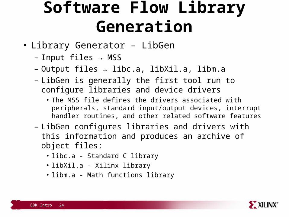
• Library Generator – LibGen– Input files → MSS– Output files → libc.a, libXil.a, libm.a– LibGen is generally the first tool run to configure libraries and device
drivers• The MSS file defines the drivers associated with peripherals, standard
input/output devices, interrupt handler routines, and other related software features
– LibGen configures libraries and drivers with this information and produces an archive of object files:
• libc.a - Standard C library• libXil.a - Xilinx library• libm.a - Math functions library
EDK Intro 25
Software FlowCompilation
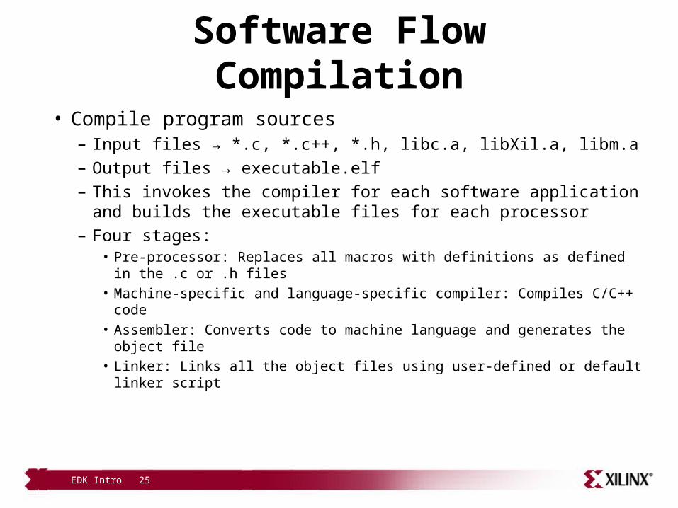
• Compile program sources– Input files → *.c, *.c++, *.h, libc.a, libXil.a, libm.a– Output files → executable.elf– This invokes the compiler for each software application and builds
the executable files for each processor– Four stages:
• Pre-processor: Replaces all macros with definitions as defined in the .c or .h files
• Machine-specific and language-specific compiler: Compiles C/C++ code• Assembler: Converts code to machine language and generates the object
file• Linker: Links all the object files using user-defined or default linker script
EDK Intro 26
Merging Hardware and Software Flows
data2MEM
download.bit
MicroBlaze™/PPC
UART
Arbiter
GPIO
Hardware Flow
SoftwareFlow
EDK Intro 27
Merging Hardware and Software Flows
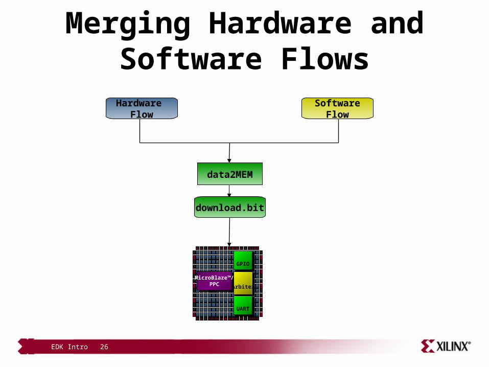
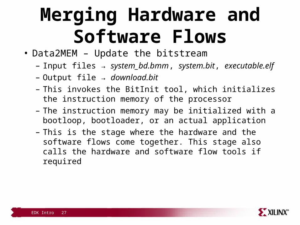
• Data2MEM – Update the bitstream– Input files → system_bd.bmm, system.bit, executable.elf– Output file → download.bit– This invokes the BitInit tool, which initializes the instruction
memory of the processor– The instruction memory may be initialized with a bootloop,
bootloader, or an actual application – This is the stage where the hardware and the software flows
come together. This stage also calls the hardware and software flow tools if required
EDK Intro 28
Configuring the FPGA
• Download the bitstream– Input file → download.bit– This downloads the download.bit file onto the target board
using the Xilinx iMPACT tool in batch mode– XPS uses the etc/download.cmd file for downloading the
bitstream• The download.cmd file contains information such as the type of cable is
used and the position of the FPGA in a JTAG chain
EDK Intro 29
Outline
• Introduction• EDK
– Overview of EDK– Embedded Development Design Flow– XPS Platform Management
• Supported Platforms• Appendix: Project Files and
Structures
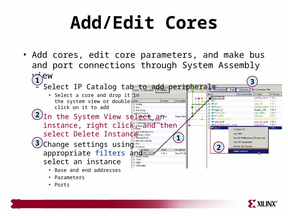
Add/Edit Cores
• Add cores, edit core parameters, and make bus and port connections through System Assembly view– Select IP Catalog tab to add peripherals
• Select a core and drop it in the system view or double-click on it to add
– In the System View select an instance, right click, and then select Delete Instance
– Change settings using appropriate filters and select an instance
• Base and end addresses• Parameters • Ports
1
1
2
23
3
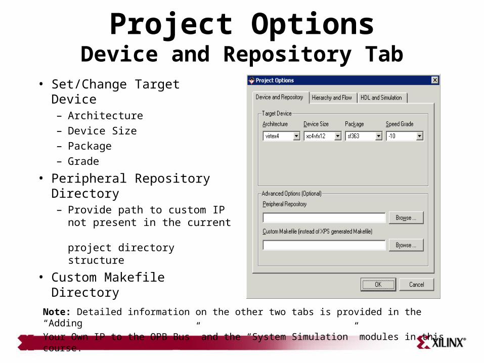
Project OptionsDevice and Repository Tab
• Set/Change Target Device– Architecture– Device Size– Package– Grade
• Peripheral Repository Directory– Provide path to custom IP
not present in the current project directory structure
• Custom Makefile Directory
Note: Detailed information on the other two tabs is provided in the “AddingYour Own IP to the OPB Bus” and the “System Simulation” modules in this course.
EDK Intro 32
Outline
• Introduction• EDK
– Project Management– Software Application Management– Platform Management
• Supported Platforms• Appendix: Project Files and
Structures
EDK Intro 33
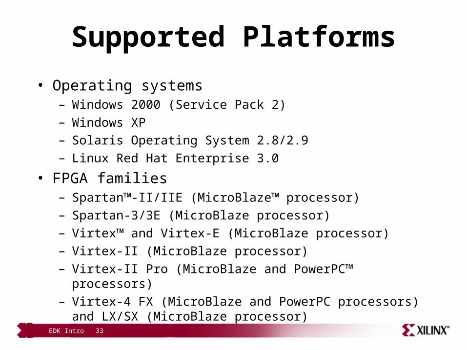
Supported Platforms
• Operating systems– Windows 2000 (Service Pack 2)– Windows XP– Solaris Operating System 2.8/2.9– Linux Red Hat Enterprise 3.0
• FPGA families– Spartan™-II/IIE (MicroBlaze™ processor)– Spartan-3/3E (MicroBlaze processor)– Virtex™ and Virtex-E (MicroBlaze processor)– Virtex-II (MicroBlaze processor)– Virtex-II Pro (MicroBlaze and PowerPC™ processors)– Virtex-4 FX (MicroBlaze and PowerPC processors) and LX/SX (MicroBlaze
processor)
EDK Intro 34
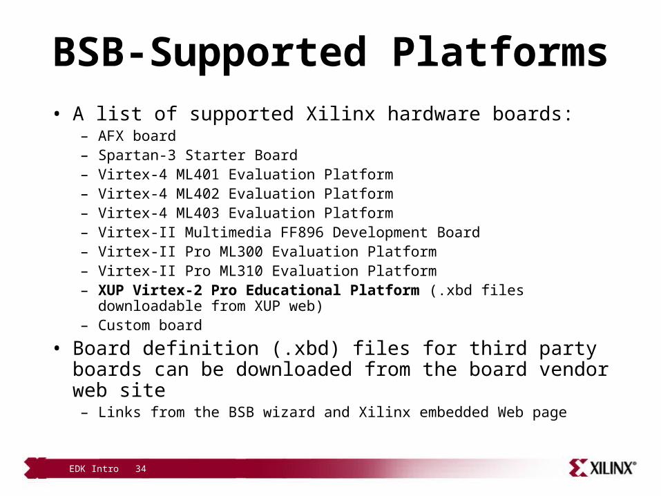
BSB-Supported Platforms• A list of supported Xilinx hardware boards:
– AFX board– Spartan-3 Starter Board– Virtex-4 ML401 Evaluation Platform– Virtex-4 ML402 Evaluation Platform– Virtex-4 ML403 Evaluation Platform– Virtex-II Multimedia FF896 Development Board– Virtex-II Pro ML300 Evaluation Platform– Virtex-II Pro ML310 Evaluation Platform– XUP Virtex-2 Pro Educational Platform (.xbd files downloadable from XUP web)– Custom board
• Board definition (.xbd) files for third party boards can be downloaded from the board vendor web site
– Links from the BSB wizard and Xilinx embedded Web page
EDK Intro 35
Knowledge Check
• What is the MHS file?
• What does the PlatGen tool do?
• What tool is used to place executable code in an FPGA block RAM?
EDK Intro 36
Answers
• What is the MHS file? – The MHS file is the Microprocessor Hardware Specification; it specifies
processors, hardware peripherals, bus connections, and address spaces for the hardware
• What does the PlatGen tool do?– PlatGen takes the MHS file and creates the system and peripheral
netlists, HDL wrapper files, BMM file, etc.
• What tool is used to place executable code in an FPGA block RAM?– The Data2Mem tool will take the BMM file and create the proper
initialization for the block RAM that is assigned to the executable memory space
EDK Intro 37
Knowledge Check
• How can you add or change configuration settings once the hardware system is build?
• What does the LibGen tool do?
• What is the difference between system.bit and download.bit files?
EDK Intro 38
Answers
• How can you add or change configuration settings once the hardware system is build? – Select IP Catalog tab, expand related IP peripheral folder, select a desired
IP, and double-click on it to add it to the design– Select an IP instance in the System Assembly View panel, right click on it,
and select desired configuration
• What does the LibGen tool do?– Read MSS file and generate libraries
• What is the difference between system.bit and download.bit files?– The system.bit file contains only hardware description whereas
download.bit file contains both hardware description as well as executable software