Embed Size (px)
Citation preview

JNCIEJuniper® Networks Certified Internet Expert
Study Guide - Chapter 4
by Harry Reynolds
This book was originally developed by Juniper Networks Inc. in conjunction with Sybex Inc. It is being offered in electronic format because the original book (ISBN: 0-7821-4069-6) is now out of print. Every effort has been made to remove the original publisher's name and references to the original bound book and its accompanying CD. The original paper book may still be available in used book stores or by contacting, John Wiley & Sons, Publishers. www.wiley.com.
Copyright © 2004-6 by Juniper Networks Inc. All rights reserved.
This publication may be used in assisting students to prepare for a Juniper JNCIE exam but Juniper Networks Inc. cannot warrant that use of this publication will ensure passing the relevant exam.

Chapter
4
Multicast
JNCIE LAB SKILLS COVERED IN THIS CHAPTER:
�
IGMP
�
Static joins
�
DVMRP
�
PIM
�
Dense mode�
Sparse mode (Bootstrap and Auto-RP)
�
MSDP
�
Any-Cast RP�
Interdomain

This chapter exposes the reader to a variety of JNCIE-level configuration scenarios that validate a candidate’s theoretical and practical understanding of multicast technology on M-series
and T-series routing platforms. It is assumed that the reader already has a working knowledge of multicast protocols and their operation, to the extent covered in the
JNCIS Study Guide
(Sybex, 2003).
Juniper Networks routing platforms support a variety of multicast protocols and standards, including Internet Group Management Protocol (IGMP) versions 1, 2, and 3, Distance Vector Multicast Routing Protocol (DVMRP), Protocol Independent Multicast (PIM) versions 1 and 2 (in both dense and sparse mode), Session Announcement Protocol (SAP), Session Discovery Protocol (SDP), and Multicast Source Discovery Protocol (MSDP). Note that a tunnel services (TS) Physical Interface Card (PIC) is required when supporting DVMRP tunnels across non-multicast enabled network elements. A TS is also needed at the Rendezvous Point (RP) and in first hop routers (those routers with directly attached multicast sources), when deploying a PIM sparse mode topology.
Use the
show
chassis
fpc
pic-status
command to determine if your router is equipped with a TS PIC:
lab@montreal>
show chassis fpc pic-status
Slot 0 Online
PIC 0 4x OC-3 SONET, SMIR
PIC 2 2x OC-3 ATM, MM
Slot 3 Online
PIC 1 4x OC-3 SONET, MM
Slot 6 Online
PIC 0 1x G/E, 1000 BASE-SX
PIC 1 1x G/E, 1000 BASE-SX
PIC 2 1x Tunnel
Slot 7 Online
Note that the absence of a TS PIC can have a dramatic impact on the overall success of a given multicast design. A prepared JNCIE candidate will know when (and where) TS PICs are needed, and will be ready to perform inventory steps on their test bed to ensure that their network design makes appropriate
use of routers that are outfitted with TS PICs.

Multicast
405
The chapter’s case study is designed to closely approximate a typical JNCIE multicast configuration scenario. Examples of key operational mode command output are provided to allow for an operational comparison of your network to that of a known good example. Examples of baseline configuration modifications that are known to meet all case study requirements are provided at the end of the case study for all routers in the multicasttest bed.
The examples demonstrated in the chapter body are based on the IS-IS baseline configuration as discovered in the case study for Chapter 1, “Network Discovery and Verification.” If you are unsure as to the state of your test bed, you should take a few moments to load up and confirm the operation of the IS-IS discovery configuration before proceeding. Figure 4.1 reviews the IS-IS IGP discovery findings from the case study in Chapter 1.
F I G U R E 4 . 1
Summary of IS-IS IGP discovery
Notes:
Multi-level IS-IS, Areas 0001 and 0002 with ISO NET based on router number.
lo0 address of r3 and r4 not injected into Area 0001 to ensure optimal forwarding between 10.0.3.3 and 10.0.3.4.
Passive setting on r5's core interfaces for optimal Area 0002-to-core routing.
No authentication or route summarization. Routing policy at r5 to leak L1 externals (DC routes) to L2.
Suboptimal routing detected at the data center and at r1/r2 for some locations. This is the result of random nexthopchoice for data center's default, and the result of r1 and r2's preference for r3's RID over r4 with regard to the10.0/16 route. This is considered normal behavior, so no corrective actions are taken.
Redistribution of static default route to data center from both r6 and r7. Redistribution of 192.168.0/24 through192.168.3/24 routes from RIP into IS-IS by both r6 and r7.
All adjacencies are up, reachability problem discovered at r1 and r2 caused by local aggregate definition. Correctedthrough IBGP policy to effect 10.0/16 route advertisement from r3 and r4 to r1 and r2; removed local aggregatefrom r1 and r2.
Area 0001L1
L2 Area 0002L1
r2 r4r7
r6
RIP v2
DataCenter
r5
r3r1
M5M5
M5M5
M5M5
(192
.168
.0-3
)
M5M5
M5M5
M5M5
M5M5
IS-ISPassive
IS-ISPassive
IS-ISPassive
IS-ISPassive
DataCenter

406
Chapter 4 �
Multicast
IGMP
The Internet Group Management Protocol (IGMP) is used by hosts and routers to determine whether there are any attached listeners for a given multicast group address (G). Routers will stop forwarding traffic addressed to G when the IGMP protocol indicates that no attached hosts are interested in the corresponding traffic. IGMP uses a variety of timers, and the con-cept of a querier router, to facilitate and control the exchange of IGMP messages on a given subnet.
By default, IGMP version 2 is enabled on all broadcast interfaces when you configure PIM or DVMRP on that interface. You must explicitly enable IGMP on point-to-point interfaces when needed; the default JUNOS software behavior reflects the fact that multicast hosts are normally attached to routers using some form of Ethernet topology while point-to-point links are normally used to interconnect routers themselves.
After verifying the operation of the baseline network using the steps outlined in previous chapters, your multicast configuration scenario begins with these IGMP configuration requirements:�
Enable IGMP version 3 to MR1. You must not configure PIM or DVMRP at this time.�
Configure
r5
to wait no more than 5 seconds for IGMP responses.�
Without interacting with MR1, ensure that
r5
displays a
∗
,G join for group 225.0.0.1.
Figure 4.2 focuses on the subset of routers that make up the multicast test bed and provides additional details about the multicast receiver, MR1.
F I G U R E 4 . 2
Multicast test bed topology
M5M5
M5M5
M5M5
M5M5
fe-0/0/1fe-0/0/0
r1
r2
r3
fe-0/0/3
fe-0/0/0 fe-0/0/1 fe-0/0/1
fe-0/0/2
10.0
.5/2
4
10.0
.4.4
/30
fe-0/0/3
fe-0/0/010.0.4.12/30
10.0.2.4/30
10.0.2.0/30
10.0.2.8/30
so-0/
1/1so-0/1/0
so-0/1/0
at-0/1/0
at-0/2/1
.1 .14 .13
.9
.1
.1.5
.18
.2 .10 .910.0.4.8/30
10.0.4.16/30
fe-0/0
/1
fe-0/0
/2 10.0.
4.0/30
fe-0/0/2.2 .17
.6 .10
.2.5
r4
Loopbacks
r1 = 10.0.6.1r2 = 10.0.6.2r3 = 10.0.3.3r4 = 10.0.3.4r5 = 10.0.3.5
.6
so-0/2/0
M5M5
.1
.2
fe-0
/0/3
172.16.30/24
r5
.200
MS1
MR1

IGMP
407
Configuring IGMP
You begin at
r5
by configuring its fe-0/0/3 interface for proper connectivity to the MR1 device:
[edit interfaces]
lab@r5#
set fe-0/0/3 unit 0 family inet address 172.16.30.1/24
The modified configuration is displayed for confirmation:
[edit interfaces]
lab@r5#
show fe-0/0/3
unit 0 {
family inet {
address 172.16.30.1/24;
}
}
The following command sequence correctly configures IGMP for the criteria posed in this example:
[edit protocols igmp]
lab@r5#
set query-response-interval 5
[edit protocols igmp]
lab@r5#
set interface fe-0/0/3 version
3
[edit protocols igmp]
lab@r5#
set interface fe-0/0/3 static group 225.0.0.1
The configuration changes are displayed:
[edit protocols igmp]
lab@r5#
show
query-response-interval 5;
interface fe-0/0/3.0 {
version 3;
static {
group 225.0.0.1;
}
}
Note that the query-response-interval has been set to the required 5 seconds, and that IGMP version 3 has been specified. The static join does not include a source address, which correctly meets the stipulations that you create a
∗
,G join state. Note that including a source address results in a S,G state for that particular source. Satisfied with your changes, you commit your candidate configuration at
r5
:
[edit protocols igmp]
lab@r5#
commit and-quit

408
Chapter 4 �
Multicast
commit complete
Exiting configuration mode
lab@r5>
Verifying IGMP
Multicast protocols can take a rather long time to converge. Candidates that are not experienced with multicast protocols sometimes postpone (or prevent) proper operation by continuously changing their configurations, or by constantly restarting
rpd
or rebooting the router. By way of example, a PIM bootstrap router will remain in the candidate state for at least 60 seconds, during which time it monitors bootstrap messages in an attempt to determine whether it will remain a BSR candidate or be elected the BSR. During this time, other routers will not learn of this router’s candidate RP status. In some cases, a restart of the routing daemon may expedite multicast protocol convergence, because restarting
rpd
may eliminate state information that would otherwise have to age out. The bottom line with multicast convergence is that when you think you have waited long enough for some multicast related protocol to “do its thing,” you are well advised to wait “some more” before making changes to your
configuration.
The verification of your IGMP configuration begins with the determination that
r5
’s fe-0/0/3 interface is operational:
lab@r5>
show interfaces fe-0/0/3 terse
Interface Admin Link Proto Local Remote
fe-0/0/3 up up
fe-0/0/3.0 up up inet 172.16.30.1/24
The display confirms that the fe-0/0/3 interface is operational and provides you with an ideal opportunity to reconfirm that the correct address was assigned. A ping test is now performed to MR1 to verify interface operation:
lab@r5>
ping 172.16.30.2 count 2
PING 172.16.30.2 (172.16.30.2): 56 data bytes
--- 172.16.30.2 ping statistics ---
2 packets transmitted, 0 packets received, 100% packet loss
Noting that the ping test fails, you decide to examine the Address Resolution Protocol (ARP) cache on
r5
:
lab@r5>
show arp
MAC Address Address Name Interface
00:b0:d0:10:73:2f 10.0.1.100 10.0.1.100 fxp0.0
00:03:47:42:37:7c 10.0.1.102 10.0.1.102 fxp0.0

IGMP
409
Total entries: 2
lab@r5>
The absence of an ARP entry for the MR1 device helps to explain why the ping test between
r5
and MR1 fails. These symptoms could indicate interface configuration mistakes, hardware malfunctions, or that the MR1 device does not really exist. Lacking access to the MR1 device, there is little you can do to fault isolate this situation further without assistance from the proc-tor. In this case, assume that the proctor has confirmed that the lack of ARP entry and IGMP echo failures are “normal.” This feedback provides a strong clue that the MR1 device does not really exist, or that it is some type of test equipment such as a packet sniffer. The lack of a multi-cast receiver should not impair your ability to configure and verify multicast forwarding as long as you are able to create static IGMP joins that direct traffic out any interfaces associated with identified multicast receivers.
Having gone as far as you can with regard to verification of the link between
r5
and MR1, you decide to move on to IGMP verification:
lab@r5>
show igmp interface
Interface: fe-0/0/3.0
Querier: 172.16.30.1
State: Up Timeout: None Version: 3 Groups: 1
Configured Parameters:
IGMP Query Interval: 125.0
IGMP Query Response Interval: 5.0
IGMP Last Member Query Interval: 1.0
IGMP Robustness Count: 2
Derived Parameters:
IGMP Membership Timeout: 255.0
IGMP Other Querier Present Timeout: 252.500000
The highlighted entries confirm that the fe-0/0/3 interface is considered “up” from the per-spective of IGMP, that IGMP version 3 is configured, that r5 is the querier for the 172.16.30/24 subnet, and that the response interval has been correctly set to 5 seconds. The indication that a single multicast group is active on this interface is also highlighted. Your next command displays information about active multicast groups:
lab@r5> show igmp group
Interface: fe-0/0/3.0
Group: 225.0.0.1
Source: 0.0.0.0 Last Reported by: 0.0.0.0
Timeout: 0 Type: Static
The output confirms the presence of a static join to group 225.0.0.1 for traffic generated by any source address (0.0.0.0). The display confirms that you have correctly configured IGMP

410 Chapter 4 � Multicast
and the static ∗,G join state, as outlined by the restrictions in this configuration example. Displaying general IGMP statistics often helps to draw attention to problem areas:
lab@r5> show igmp statistics
IGMP packet statistics for all interfaces
IGMP Message type Received Sent Rx errors
Membership Query 0 10 0
V1 Membership Report 0 0 0
DVMRP 0 0 0
PIM V1 0 0 0
Cisco Trace 0 0 0
V2 Membership Report 0 0 0
Group Leave 0 0 0
Mtrace Response 0 0 0
Mtrace Request 0 0 0
Domain Wide Report 0 0 0
V3 Membership Report 0 0 0
Other Unknown types 0
IGMP v3 unsupported type 0
IGMP v3 source required for SSM 0
IGMP v3 mode not applicable for SSM 0
IGMP Global Statistics
Bad Length 0
Bad Checksum 0
Bad Receive If 0
Rx non-local 0
The statistics output indicates that no protocol errors are occurring and that r5 has sent 10 membership queries since the statistics were cleared (or started in this case). Considering that there are no active multicast receives attached to r5 at this time, the lack of membership reports and group leave messages is normal in this case. IGMP statistics can be cleared with the clear igmp statistics operational mode command. Although not called for in this example, IGMP tracing may prove invaluable when troubleshooting group join and leave issues. The highlights in the next capture call out a typical IGMP tracing configuration:
[edit protocols igmp]
lab@r5# show
traceoptions {
file igmp;
flag leave detail;
flag report detail;
flag query detail;
}

IGMP 411
query-response-interval 5;
interface fe-0/0/3.0 {
version 3;
static {
group 225.0.0.1;
}
}
The trace output garnered from this configuration indicates that the only IGMP traffic present on the 172.16.30/24 subnet is in the form of version 3 membership queries. This is expected, considering the lack of multicast receivers on this subnet:
[edit protocols igmp]
lab@r5# run monitor start igmp
[edit protocols igmp]
lab@r5#
*** igmp ***
Mar 26 14:27:37 IGMP SENT 172.16.30.1 -> 224.0.0.1 Membership Query(v3): length 12 intvl 5
lab@r5# Mar 26 14:29:39 IGMP SENT 172.16.30.1 -> 224.0.0.1 Membership Query(v3): length 12 intvl 5
Mar 26 14:31:41 IGMP SENT 172.16.30.1 -> 224.0.0.1 Membership Query(v3): length 12 intvl 5
The IGMP verification steps shown in this section have all indicated that IGMP is opera-tional and configured in accordance with the provided criteria.
IGMP Summary
IGMP is used by routers and multicast receivers to communicate group membership status. IGMP is used by multicast receivers only. Note that multicast senders are not required to join any multicast groups; therefore, a multicast sender does not have to support the IGMP protocol.
The operation of IGMP ensures that routers will stop forwarding multicast traffic to a given subnet shortly after the last interested host indicates that it no longer wishes to receive traffic for that group. By default, JUNOS software operates according to IGMP version 2; you can explicitly configure IGMP version 1 or 3 as needed. A router configured for IGMP version 3 will fall back to IGMP version 2 (or 1) when needed, but this behavior will prevent version 3 features, such as Source Specific Multicast (SSM), from functioning.
IGMP is automatically enabled on broadcast interfaces when PIM or DVMRP is enabled on that interface. You can explicitly configure IGMP when needed, such as in the case of a point-to-point interface, or when interface-specific behavior is desired. You can configure static IGMP join state to help test and verify multicast forwarding in the absence of multicast

412 Chapter 4 � Multicast
receivers. The static join can take the form of a ∗,G or S,G entry, based on the inclusion of a source address in the latter case. You need to include a source address when configuring a static SSM join.
The operation of IGMP can be verified with a variety of operational mode commands that were demonstrated in this section. You can also trace IGMP protocol exchanges to assist in fault isolation.
DVMRPThis section details a typical Distance Vector Multicast Routing Protocol (DVMRP) configuration scenario. Various verification and confirmation techniques for general multicast routing, and for DVMRP in particular, are provided in the confirmation section.
DVMRP operates much like the RIP protocol, in that it is based on the periodic announce-ment (every 60 seconds) of multicast reachability (a vector) along with an associated metric (distance) to all neighboring DVMRP routers. DVMRP is a dense protocol that operates according to a flood and prune model. By default, all multicast traffic is flooded away from the source (according to Reverse Path Forwarding [RPF] procedures) to all downstream nodes using what is called a truncated broadcast tree. Leaf nodes with no interested listeners send prune messages to their upstream neighbors to cease the flow of multicast traffic for that particular ∗,G entry. DVMRP supports a graft mechanism that allows the rapid removal of prune state in the event that a multicast receiver expresses interest in a previously pruned group.
The DVMRP protocol represents infinity with a metric of 32; however, the protocol uses poison reverse in a unique way. Specifically, a router that considers itself to be downstream for a particular source prefix adds 32 to the received route metric, and then proceeds to advertise the “poisoned” route back to the neighbor it was learned from. Upon seeing the poison reverse metric setting, the upstream neighbor adds the interface associated withthe downstream router into its outgoing interface list (OIL). Figure 4.3 illustrates this behav-ior in the context of r3 and r5 for the 10.0.5.200/24 prefix associated with MS1. In this case, the 10.0.5/24 route is advertised by r3 to r5 with a metric of 2. r5 adds 1 to the revived metric upon receipt. After determining that it wishes to be added to r3’s OIL for the 10.0.5/24 route, r5 adds 32 to the route metric and sends the route back to r3, now with a metricof 35.
The hardest part about configuring DVMRP relates to the need for a multicast specific routing table, which is used by DVMRP to store and advertise multicast routes. To facilitate Reverse Path Forwarding (RPF) checks, you must ensure that interface routes are also placed into this routing table. These requirements necessitate the use of RIB groups, which are a common source of confusion for the uninitiated. Juniper Networks recommends that you use the inet.2 routing table to house your interface and DVMRP routes, and the examples in this section are in line with this recommendation.

DVMRP 413
F I G U R E 4 . 3 DVMRP poison reverse
To complete this section, you must alter your configurations to meet these criteria:� Configure DVMRP on r1, r2, r3, r4, and r5 so that multicast traffic sent from MS1 to
group 225.0.0.1 is made available to MR1.� Configure DVMRP to wait 40 seconds before it declares the loss of a neighbor.� Adjust DVMRP metrics to ensure that traffic from MS1 to MR1 transits the 10.0.2.8/30
subnet between r4 and r5.
Configuring DVMRP
You start DVMRP configuration on r5 by creating an interface RIB group called interface-rib, which is used to populate the inet.2 routing table with interface routes. Interface routes are needed to perform RPF checks:
[edit routing-options]
lab@r5# set interface-routes rib-group inet interface-rib
The next set of commands instructs r5 to copy the contents of the interface-rib into both the inet.0 and inet.2 routing tables:
[edit routing-options]
Mar 27 13:32:58 DVMRP SENT 10.0.2.1 224.0.0.4 len 70 Report: Vers: 3.255
Mar 27 13:32:58 mask 255.255.255.255: 10.0.6.1 35
mask 255.255.255.252: 10.0.2.4 34 10.0.4.16 35
Mar 27 13:32:58 mask 255.255.255.0: 10.0.5.0 35
[DVMRP Report Tracing at r5:]
M5M5 M5M5fe-0/0/1fe-0/0/0
r1 r3
10.0
.5/2
4
fe-0/0/0.1 .14 .13
at-0/1/0at-0/2/110.0.2.0/3010.0.4.12/30 .2
M5M5.1
.1
.2
fe-0
/0/3
172.16.30/24
r5
10.0.5/24, Metric 2
10.0.5/24, Metric 35
.200
MS1
MR1

414 Chapter 4 � Multicast
lab@r5# set rib-groups interface-rib import-rib inet.0
[edit routing-options]
lab@r5# set rib-groups interface-rib import-rib inet.2
The final RIB-related configuration steps relate to the creation of a RIB group for DVMRP, which is called dvmrp-rg in this example. The dvmrp-rg is associated with the DVMRP protocol in a subsequent configuration step. The import and export RIB statements instruct the dvmrp-rg group to import and export routes from the inet.2 routing table:
[edit routing-options]
lab@r5# set rib-groups dvmrp-rg import-rib inet.2
[edit routing-options]
lab@r5# set rib-groups dvmrp-rg export-rib inet.2
The RIB group configuration in support of DVMRP is shown at r5, with recent changes highlighted:
[edit routing-options]
lab@r5# show
interface-routes {
rib-group inet interface-rib;
}
static {
route 10.0.200.0/24 {
next-hop 10.0.1.102;
no-readvertise;
}
}
rib-groups {
interface-rib {
import-rib [ inet.0 inet.2 ];
}
dvmrp-rg {
export-rib inet.2;
import-rib inet.2;
}
}
autonomous-system 65412;
The DVMRP protocol is now configured at r5. In this example, the all keyword is used to save some typing by enabling DVMRP on all of the router’s interfaces. Because the all shortcut catches the OoB interface, the router’s fxp0 interface is explicitly disabled to ensure that DVMRP does not attempt to operate over the OoB network:
[edit protocols dvmrp]
lab@r5# set interface all hold-time 40

DVMRP 415
[edit protocols dvmrp]
lab@r5# set interface fxp0 disable
[edit protocols dvmrp]
lab@r5# set rib-group dvmrp-rg
The completed DVMRP stanza at r5 is displayed:
[edit protocols dvmrp]
lab@r5# show
rib-group dvmrp-rg;
interface all {
hold-time 40;
}
interface fxp0.0 {
disable;
}
The specification of the RIB group that is to be used by DVMRP is critical. In this example, you can see the correct specification of the dvmrp-rg RIB group. Recall that previous RIB group configuration steps in this section function to link the dvmrp-rg to the inet.2 routing table for route import and export purposes.
Although not shown, a similar DVMRP configuration is needed on r1, r2, r3, and r4. You might consider the use of load merge terminal to replicate the basic DVMRP configuration in these routers. A sample configuration that highlights the DVMRP changes at r3 is shown next:
lab@r3# show routing-options
interface-routes {
rib-group inet interface-rib;
}
static {
route 10.0.200.0/24 {
next-hop 10.0.1.102;
no-readvertise;
}
}
aggregate {
route 10.0.0.0/16;
}
rib-groups {
interface-rib {
import-rib [ inet.0 inet.2 ];
}
dvmrp-rg {
export-rib inet.2;
import-rib inet.2;

416 Chapter 4 � Multicast
}
}
autonomous-system 65412;
[edit]
lab@r3# show protocols dvmrp
rib-group dvmrp-rg;
interface all {
hold-time 40;
}
interface fxp0.0 {
disable;
}
With similar changes in r1 through r5, you commit your configurations and proceed to the verification section. Note that additional configuration changes may be required to ensure that multicast traffic from MS1 to MR1 traverses the POS link between r4 and r5.
Verifying DVMRP
When testing DVMRP with the 5.6R2.4 code installed in the test bed, this author encountered a known bug that prevented proper operation. The bug is tracked under PR 32590. At the time of this writing, the fix for the problem was available only in the 5.x release train through a daily JUNOS software build, which was loaded to allow confirmation of DVMRP operation. Candidates should expect to find only production releases of JUNOS software in the actual JNCIE test bed. The 5.6R2.4 production code will be reloaded onto the routers at the conclusion of DVMRP testing.
You begin verification of DVMRP by confirming the presence of interface (and DVMRP) routes in the inet.2 table:
[edit]
lab@r3# run show route table inet.2
inet.2: 27 destinations, 27 routes (27 active, 0 holddown, 0 hidden)
+ = Active Route, - = Last Active, * = Both
10.0.1.0/24 *[Direct/0] 03:21:36
> via fxp0.0
10.0.1.3/32 *[Local/0] 03:10:05
Local via fxp0.0
10.0.2.0/30 *[Direct/0] 03:21:36
> via at-0/1/0.0

DVMRP 417
10.0.2.2/32 *[Local/0] 03:10:05
Local via at-0/1/0.0
10.0.2.4/30 *[Direct/0] 02:52:57
> via so-0/2/0.100
10.0.2.5/32 *[Local/0] 02:52:57
Local via so-0/2/0.100
10.0.2.8/30 *[DVMRP/110] 00:00:46, metric 2
> to 10.0.2.1 via at-0/1/0.0
10.0.2.12/30 *[Direct/0] 03:12:54
> via fe-0/0/3.0
10.0.2.14/32 *[Local/0] 03:10:05
Local via fe-0/0/3.0
10.0.2.16/30 *[DVMRP/110] 00:00:46, metric 2
> to 10.0.2.6 via so-0/2/0.100
10.0.3.3/32 *[Direct/0] 03:21:36
> via lo0.0
10.0.3.4/32 *[DVMRP/110] 00:00:46, metric 2
> to 10.0.2.6 via so-0/2/0.100
10.0.3.5/32 *[DVMRP/110] 00:00:46, metric 2
> to 10.0.2.1 via at-0/1/0.0
10.0.4.0/30 *[Direct/0] 00:54:36
> via fe-0/0/1.0
10.0.4.1/32 *[Local/0] 00:54:36
Local via fe-0/0/1.0
10.0.4.4/30 *[DVMRP/110] 00:00:46, metric 2
> to 10.0.4.2 via fe-0/0/1.0
10.0.4.8/30 *[DVMRP/110] 00:00:46, metric 2
> to 10.0.4.2 via fe-0/0/1.0
10.0.4.12/30 *[Direct/0] 02:59:03
> via fe-0/0/0.0
10.0.4.13/32 *[Local/0] 02:59:03
Local via fe-0/0/0.0
10.0.4.16/30 *[DVMRP/110] 00:00:46, metric 2
> to 10.0.2.6 via so-0/2/0.100
10.0.5.0/24 *[DVMRP/110] 00:00:46, metric 2
> to 10.0.4.2 via fe-0/0/1.0
10.0.6.1/32 *[DVMRP/110] 00:00:46, metric 2
> to 10.0.4.14 via fe-0/0/0.0
10.0.6.2/32 *[DVMRP/110] 00:00:46, metric 2
> to 10.0.4.2 via fe-0/0/1.0
10.0.8.4/30 *[DVMRP/110] 00:00:46, metric 2
> to 10.0.2.1 via at-0/1/0.0

418 Chapter 4 � Multicast
10.0.8.8/30 *[DVMRP/110] 00:00:46, metric 2
> to 10.0.2.1 via at-0/1/0.0
172.16.0.13/32 *[Local/0] 03:10:05
Reject
172.16.30.0/24 *[DVMRP/110] 00:00:46, metric 2
> to 10.0.2.1 via at-0/1/0.0
The inet.2 routing table on r3 contains the expected interface routes, as well as entries learned through DVMRP. The highlighted entry calls out the 172.16.30/24 prefix associated with MR1. You may assume that r1 through r4 have similar entries in their inet.2 routing tables. Displays such as this one indicate that your interface and dvmrp-rg RIB groups are correctly configured. The next confirmation step involves the verification of DVMRP neighbor status at r1 through r5:
[edit]
lab@r4# run show dvmrp neighbors
Neighbor Interface Version Flags Routes Timeout Transitions
10.0.4.10 fe-0/0/1.0 3.255 PGM 4 31 2
10.0.4.18 fe-0/0/2.0 3.255 PGM 1 32 1
10.0.2.5 so-0/1/0.100 3.255 PGM 4 33 1
10.0.2.9 so-0/1/1.0 3.255 PGM 4 33 1
The sample display, which was obtained at r5, confirms that all expected DVMRP neighbors are present and that two-way communications has been successfully established. Note that two-way communications is indicated by the absence of a 1 in the Flags column. The indication that routes have been received from each neighbor provides additional confirmation that DVMRP is working properly. Though not shown, you can assume that all DVMRP neighbors are cor-rectly listed for all routers in the multicast test bed. The next command verifies that the correct routes are being advertised and received thorough the DVMRP protocol:
[edit protocols igmp]
lab@r5# run show route protocol dvmrp
inet.0: 36 destinations, 44 routes (36 active, 0 holddown, 4 hidden)
+ = Active Route, - = Last Active, * = Both
224.0.0.4/32 *[DVMRP/0] 01:06:23
MultiRecv
inet.1: 1 destinations, 1 routes (1 active, 0 holddown, 0 hidden)
+ = Active Route, - = Last Active, * = Both
225.0.0.1,10.0.5.200/32*[DVMRP/110] 00:32:29
Multicast (IPv4)

DVMRP 419
inet.2: 26 destinations, 26 routes (26 active, 0 holddown, 0 hidden)
+ = Active Route, - = Last Active, * = Both
10.0.2.4/30 *[DVMRP/110] 00:00:27, metric 2
> to 10.0.2.2 via at-0/2/1.0
10.0.2.12/30 *[DVMRP/110] 00:00:27, metric 2
> to 10.0.2.2 via at-0/2/1.0
10.0.2.16/30 *[DVMRP/110] 00:00:29, metric 2
> to 10.0.2.10 via so-0/1/0.0
10.0.3.3/32 *[DVMRP/110] 00:00:27, metric 2
> to 10.0.2.2 via at-0/2/1.0
10.0.3.4/32 *[DVMRP/110] 00:00:29, metric 2
> to 10.0.2.10 via so-0/1/0.0
10.0.4.0/30 *[DVMRP/110] 00:00:29, metric 3
> to 10.0.2.10 via so-0/1/0.0
10.0.4.4/30 *[DVMRP/110] 00:00:27, metric 3
> to 10.0.2.2 via at-0/2/1.0
10.0.4.8/30 *[DVMRP/110] 00:00:29, metric 2
> to 10.0.2.10 via so-0/1/0.0
10.0.4.12/30 *[DVMRP/110] 00:00:27, metric 2
> to 10.0.2.2 via at-0/2/1.0
10.0.4.16/30 *[DVMRP/110] 00:00:29, metric 2
> to 10.0.2.10 via so-0/1/0.0
10.0.5.0/24 *[DVMRP/110] 00:00:27, metric 3
> to 10.0.2.2 via at-0/2/1.0
10.0.6.1/32 *[DVMRP/110] 00:00:27, metric 3
> to 10.0.2.2 via at-0/2/1.0
10.0.6.2/32 *[DVMRP/110] 00:00:27, metric 3
> to 10.0.2.2 via at-0/2/1.0
iso.0: 1 destinations, 1 routes (1 active, 0 holddown, 0 hidden)
All the expected DVMRP routes are present. The highlights call out the fact that the DVMRP routes are installed into the inet.2 routing table, and the presence of the 10.0.5/24 route asso-ciated with the multicast sender, MS1. The metric for this route is set to 3, which correctly reflects the hop count (+1) between r5 and the 10.0.5/24 subnet. Note that the inet.1 routing table functions as a cache that houses transit multicast state. In this example, the inet.1 entry indicates that source 10.0.5.200 is currently sending to group 225.0.0.1. Noting that IS-IS entries also exist in the main routing table for many of the routes displayed helps to drive home the fact that DVMRP maintains a separate routing table:
[edit protocols igmp]
lab@r5# run show route 10.0.5.0/24

420 Chapter 4 � Multicast
inet.0: 36 destinations, 44 routes (36 active, 0 holddown, 0 hidden)
+ = Active Route, - = Last Active, * = Both
10.0.5.0/24 *[IS-IS/18] 01:41:27, metric 30
to 10.0.2.10 via so-0/1/0.0
> to 10.0.2.2 via at-0/2/1.0
inet.2: 26 destinations, 26 routes (26 active, 0 holddown, 0 hidden)
+ = Active Route, - = Last Active, * = Both
10.0.5.0/24 *[DVMRP/110] 00:00:10, metric 3
> to 10.0.2.2 via at-0/2/1.0
Issuing a show route receiving-protocol dvmrp neighbor command also proves helpful when monitoring and troubleshooting DVMRP operation, as shown here in the context of r3 and the routes it received from r5:
[edit]
lab@r3# run show route receive-protocol dvmrp 10.0.2.1
inet.0: 37 destinations, 45 routes (37 active, 0 holddown, 0 hidden)
inet.2: 27 destinations, 27 routes (27 active, 0 holddown, 0 hidden)
+ = Active Route, - = Last Active, * = Both
10.0.2.8/30 *[DVMRP/110] 00:00:07, metric 2
> to 10.0.2.1 via at-0/1/0.0
10.0.3.5/32 *[DVMRP/110] 00:00:07, metric 2
> to 10.0.2.1 via at-0/1/0.0
10.0.8.4/30 *[DVMRP/110] 00:00:07, metric 2
> to 10.0.2.1 via at-0/1/0.0
10.0.8.8/30 *[DVMRP/110] 00:00:07, metric 2
> to 10.0.2.1 via at-0/1/0.0
172.16.30.0/24 *[DVMRP/110] 00:00:07, metric 2
> to 10.0.2.1 via at-0/1/0.0
iso.0: 1 destinations, 1 routes (1 active, 0 holddown, 0 hidden)
Note that the show route advertising-protocol dvmrp neighbor command is currently not functional and is tracked under PR 6307.
With the gross operation of DVMRP verified, it is now time to begin analysis of actual multicast traffic flow between MS1 and MR1. You begin by verifying that the multicast traffic is actually being delivered to the MR1 subnet. You can confirm the delivery of multicast traffic by monitoring interface counters or with the contents of a show multicast route extensive
DVMRP 421
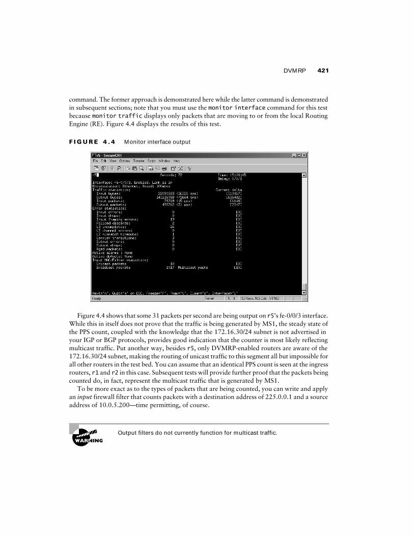
command. The former approach is demonstrated here while the latter command is demonstrated in subsequent sections; note that you must use the monitor interface command for this test because monitor traffic displays only packets that are moving to or from the local Routing Engine (RE). Figure 4.4 displays the results of this test.
F I G U R E 4 . 4 Monitor interface output
Figure 4.4 shows that some 31 packets per second are being output on r5’s fe-0/0/3 interface. While this in itself does not prove that the traffic is being generated by MS1, the steady state of the PPS count, coupled with the knowledge that the 172.16.30/24 subnet is not advertised in your IGP or BGP protocols, provides good indication that the counter is most likely reflecting multicast traffic. Put another way, besides r5, only DVMRP-enabled routers are aware of the 172.16.30/24 subnet, making the routing of unicast traffic to this segment all but impossible for all other routers in the test bed. You can assume that an identical PPS count is seen at the ingress routers, r1 and r2 in this case. Subsequent tests will provide further proof that the packets being counted do, in fact, represent the multicast traffic that is generated by MS1.
To be more exact as to the types of packets that are being counted, you can write and apply an input firewall filter that counts packets with a destination address of 225.0.0.1 and a source address of 10.0.5.200—time permitting, of course.
Output filters do not currently function for multicast traffic.

422 Chapter 4 � Multicast
An example of such an input firewall filter is shown here:
[edit]
lab@r5# show firewall filter count-mcast
term 1 {
from {
source-address {
10.0.5.200/32;
}
destination-address {
225.0.0.1/32;
}
}
then {
count mcast;
accept;
}
}
term 2 {
then accept;
}
[edit]
lab@r5# show interfaces at-0/2/1
unit 0 {
family inet {
filter {
input count-mcast;
}
address 10.0.2.1/30;
}
}
[edit]
lab@r5# show interfaces so-0/1/0
unit 0 {
family inet {
filter {
input count-mcast;
}
address 10.0.2.9/30;
}
}

DVMRP 423
With delivery of the multicast traffic confirmed at r5, your attention now shifts to the ingress routers, r1 and r2, so that you can confirm the forwarding path for the 225.0.0.1 multicast traffic:
lab@r1# run show multicast route
Family: INET
Group Source prefix Act Pru InIf NHid Session Name
225.0.0.1 10.0.5.200 /32 A P 2 0 MALLOC
The presence of a multicast cache entry for the MS1 source and the 225.0.0.1 group is a good sign. A key item to note in this display is that r1 is not forwarding this traffic, as indicated by the P value in the Pru column. In this case, the P indicates that the prefix has been pruned, in other words, that there are no outgoing interfaces. Adding the extensive switch allows you to determine the incoming rate of the multicast traffic from MS1:
[edit]
lab@r1# run show multicast route extensive
Family: INET
Group Source prefix Act Pru NHid Packets IfMismatch Timeout
225.0.0.1 10.0.5.200 /32 A P 0 293155 0 360
Upstream interface: fe-0/0/0.0
Session name: MALLOC
Forwarding rate: 13 kBps (32 pps)
Source: 10.0.5.200
Family: INET6
Group Source prefix Act Pru NHid Packets IfMismatch Timeout
Multicast Applications
While developing this chapter, this author used a combination of UNIX- and Windows-based multi-cast applications. The mgen and drec applications were used when testing with a Linux plat-form while the Wsend and Wlisten programs were used when testing with a Windows 2000 platform. As of this writing, mgen can be obtained from http://manimac.itd.nrl.navy.mil/MGEN/. The Wsend and Wlisten applications are produced by Microsoft, but an Internet source could not be located as this section was being developed. This author also found the Stream-Pump and StreamPlayer applications to be quite useful for generating and receiving multicast traffic on a Windows platform. As of this writing, you can download these applications from www.vbrick.com/freesoftware.asp.

424 Chapter 4 � Multicast
The indication that some 32 packets are received each second from the 10.0.5.200 source serves to further validate that the packet count seen on r5’s fe-0/0/3 interface is in fact the multicast traffic generated by MS1. The same command is now issued on r2:
[edit]
lab@r2# run show multicast route extensive
Family: INET
Group Source prefix Act Pru NHid Packets IfMismatch Timeout
225.0.0.1 10.0.5.200 /32 A F 97 219820 0 360
Upstream interface: fe-0/0/0.0
Session name: MALLOC
Forwarding rate: 14 kBps (34 pps)
Source: 10.0.5.200
Family: INET6
Group Source prefix Act Pru NHid Packets IfMismatch Timeout
The display from r2 confirms that it is forwarding the traffic from 10.0.5.200, as indicated by the F in the Pru column. The display further indicates that the traffic is being sent out the interface associated with a NHid of 97. The show multicast next-hops command displays the interface to NHid mapping in a most convenient fashion:
[edit]
lab@r2# run show multicast next-hops
Family: INET
ID Refcount KRefcount Downstream interface
97 2 1 fe-0/0/2.0
Family: INET6
The downstream interface listing of fe-0/0/2 tells you that traffic from MS1 is being sent from r2 to r3 over the 10.0.4.0/30 subnet. Although not shown, you can assume that a monitor interface at-0/2/1 command issued at r5 confirms that some 32 packets per second are being received from r3. The commands shown next also indicate that multicast traffic from MS1 to MR1 is being sent over the ATM link between r3 and r5, which is not in accordance with the criteria posed in this scenario:
[edit]
lab@r3# run show multicast route
Family: INET
Group Source prefix Act Pru InIf NHid Session Name
225.0.0.1 10.0.5.200 /32 A F 6 117 MALLOC

DVMRP 425
Family: INET6
Group Source prefix Act Pru InIf NHid Session Name
[edit]
lab@r3# run show multicast next-hops
Family: INET
ID Refcount KRefcount Downstream interface
117 2 1 at-0/1/0.0
Family: INET6
Well, the good news is that multicast traffic is flowing between the source and receiver subnet; the bad news is that the forwarding path does not comply with the restrictions imposed by this configuration scenario. A JNCIE candidate will have to be familiar with the operation of DVMRP to understand why this forwarding path was chosen, and more importantly, how to influence DVMRP’s forwarding paths.
In this case, r3 is receiving DVMRP advertisements for the 10.0.5/24 subnet from both r1 and r2. Because the route metrics are the same, r3 chooses the upstream router based on the lower of the two IP addresses. This results in the generation of a poison reverse advertisement to r2, but not to r1, which in turn leads to the prune/forwarding state observed at r1 and r2, respectively. Note that r2 is not forwarding to r4 at this time because r4 has generated a DVMRP prune for the S,G pair in question:
[edit]
lab@r4# run show dvmrp prunes
Group Source Prefix Timeout Neighbor
225.0.0.1 10.0.5.200 /32 1565 10.0.4.10
The prune was generated by r4 because it has no downstream interfaces associated with this S,G pair.
Modifying DVMRP Metrics
With two equal-cost paths between r5 and the source network, r5 is installing itself as a downstream node for r3, but not r4. As previously noted, this is due to r3’s lower IP address. To achieve the desired forwarding path, you need to make r5 prefer the route advertisements for the 10.0.5/24 source network from r4 over the same route that it receives from r3. Because DVMRP interface-based metric settings affect only the cost of directly connected networks, as opposed to adjusting the metrics for all updates sent out that interface, a policy-based approach for DVMRP metric setting is used in this example. Note that setting a DVMRP interface metric on r1 and/or r2 will not result in the desired forwarding path in this example because r5 still receives two equal-cost routes for the 10.0.5/24 source network, given the current test bed topology. The policy-related changes made to r3 are shown here with highlights:
[edit]
lab@r3# show policy-options policy-statement dvmrp-metric

426 Chapter 4 � Multicast
from {
route-filter 10.0.5.0/24 exact;
}
then {
metric 3;
accept;
}
[edit]
lab@r3# show protocols dvmrp
rib-group dvmrp-rg;
export dvmrp-metric;
interface all {
hold-time 40;
}
interface fxp0.0 {
disable;
}
After committing the dvmrp-metric related export policy at r3, the results are easy to confirm at r5:
[edit protocols]
lab@r5# run show route 10.0.5/24
inet.0: 36 destinations, 44 routes (36 active, 0 holddown, 4 hidden)
+ = Active Route, - = Last Active, * = Both
10.0.5.0/24 *[IS-IS/18] 00:08:15, metric 30
> to 10.0.2.10 via so-0/1/0.0
to 10.0.2.2 via at-0/2/1.0
inet.2: 26 destinations, 26 routes (26 active, 0 holddown, 0 hidden)
+ = Active Route, - = Last Active, * = Both
10.0.5.0/24 *[DVMRP/110] 00:00:45, metric 3
> to 10.0.2.10 via so-0/1/0.0
With r5 now preferring the route from r4, it generates a poison reverse update back to r4, thereby producing the desired forwarding state at r4:
lab@r4# run show multicast route
Family: INET
Group Source prefix Act Pru InIf NHid Session Name
225.0.0.1 10.0.5.200 /32 A F 6 119 MALLOC

DVMRP 427
Family: INET6
Group Source prefix Act Pru InIf NHid Session Name
[edit]
lab@r4# run show multicast next-hops
Family: INET
ID Refcount KRefcount Downstream interface
119 2 1 so-0/1/1.0
Family: INET6
The output from r4 confirms that traffic associated with the 10.0.5.200, 225.0.0.1 S,G pairing is being forwarded to r5 over its so-0/1/1 POS interface, in accordance with your restric-tions. With r4 now forwarding the multicast traffic, you expect to see that r3 has pruned this S,G entry and that it has issued a prune back to r2:
[edit]
lab@r3# run show multicast route
Family: INET
Group Source prefix Act Pru InIf NHid Session Name
225.0.0.1 10.0.5.200 /32 I P 6 0 MALLOC
Family: INET6
Group Source prefix Act Pru InIf NHid Session Name
[edit]
lab@r3# run show dvmrp prunes
Group Source Prefix Timeout Neighbor
225.0.0.1 10.0.5.200 /32 6698 10.0.4.2
The results match your expectations and provide confirmation that DVMRP has been correctly configured and is operating in full accordance with all provided guidelines and restric-tions. Before moving on, you should confirm that multicast traffic from group 225.0.0.1 is still being delivered to the MR1 subnet. Although not shown, you can assume that the multicast traffic is still being correctly delivered to the MR1 subnet.
DVMRP Tracing
Although DVMRP appears to be working fine in the current test bed, protocol tracing is an excellent way to gain additional familiarity with the normal operation of any protocol. The tracing

428 Chapter 4 � Multicast
configuration shown here provides a fair dose of meat without overwhelming the operator with meaningless details:
[edit protocols dvmrp]
lab@r3# show traceoptions
file dvmrp;
flag neighbor detail;
The trace output capture shown next was taken after the DVMRP protocol is deactivated and reactivated on r3:
[edit]
lab@r3# activate protocols dvmrp
[edit]
lab@r3# commit
commit complete
[edit]
lab@r3#
Mar 28 18:01:03 DVMRP RECV 10.0.4.14 -> 224.0.0.4 len 16 Probe: Vers: 3.255 flags: PGM genid: 0x3ef3843e nbrs: 10.0.4.13
Mar 28 18:01:03 DVMRP SENT 10.0.4.13 -> 10.0.4.14 len 42 Report: Vers: 3.255
mask 255.255.255.252:
10.0.4.0 1
Mar 28 18:01:03
mask 255.255.255.255:
10.0.3.3 1
Mar 28 18:01:03
mask 255.255.255.252:
10.0.2.12 1
10.0.2.4 1
10.0.2.0 1
Mar 28 18:01:03 DVMRP RECV 10.0.4.2 -> 224.0.0.4 len 16 Probe: Vers: 3.255 flags: PGM genid: 0x45f3843e nbrs: 10.0.4.1
Mar 28 18:01:03 DVMRP SENT 10.0.4.1 -> 10.0.4.2 len 42 Report: Vers: 3.255
mask 255.255.255.252:
10.0.4.12 1
. . .
Mar 28 18:01:14 DVMRP SENT 10.0.2.2 -> 224.0.0.4 len 44 Report: Vers: 3.255
mask 255.255.255.252:
10.0.2.8 34
Mar 28 18:01:14
mask 255.255.255.0 :
172.16.30.0 34

Protocol Independent Multicast 429
Mar 28 18:01:14
mask 255.255.255.252:
10.0.8.8 34
10.0.8.4 34
Mar 28 18:01:14
mask 255.255.255.255:
10.0.3.5 34
. . .
The trace output shows DVMRP neighbor probes, and route reports being sent and received. The truncated capture also shows some instances of DVMRP poison reverse, as indicated by metrics higher than 32.
DVMRP Summary
DVRP builds a multicast routing table that is used for RPF checks in support of multicast forwarding. Because the inet.2 routing table is designed to hold multicast routing information, it is recommended that you configure your DVMRP RIB groups to populate the inet.2 table. Successful RPF checks require the presence of directly connected interface routes in the routing table used by DVMRP. You configure an interface RIB group and link it to the DVMRP routing table to install copies of interface routes for RPF checking.
DVMRP operates neighbor to neighbor using periodic updates, in a behavior that is similar to RIP. DVMRP builds truncated multicast trees based on downstream nodes using poison reverse to indicate that they consider the upstream node to be closer to the multicast source, thereby showing the node’s desire to be added to the particular source tree. When metrics are equal, a DVMRP router breaks a tie by selecting the advertisement associated with the lowest IP address. You can adjust metrics (using policy or with direct interface settings for directly connected networks) to influence the multicast topology. You can trace the operation of DVMRP to observe neighbor establishment and routing exchanges.
This section demonstrated a number of multicast monitoring and troubleshooting techniques that can be applied to virtually any multicast network. These commands and techniques include displaying multicast routes, multicast next hops, statistics; examining RPF results; and monitoring interface traffic loads to detect the presence of multicast.
Although DVMP has lost favor to various flavors of PIM, the protocol is still in use and is supported by JUNOS software. A well-prepared JNCIE candidate will take time to hone their DVMRP configuration and troubleshooting skills to ensure that they are not caught off guard by a DVMRP configuration scenario.
Protocol Independent MulticastThis section covers various Protocol Independent Multicast (PIM) configuration scenarios. PIM gets its name from the fact that it makes use of the main routing table (inet.0) for RPF purposes, regardless of what routing protocols are used to populate the main routing table. JUNOS software supports PIM versions 1 and 2 in dense, sparse, or sparse-dense modes of operation.

430 Chapter 4 � Multicast
In dense mode, PIM uses a flood and prune model that is similar to DVMRP, the primary exception being that initial flooding is based on interfaces with detected neighbors yielding a broadcast-like behavior that is referred to as a broadcast tree. The broadcast tree morphs into a minimal spanning tree once all prune actions have occurred, however.
In most cases, PIM is deployed in a sparse mode (PIM-SM). PIM-SM makes use of a Rendezvous Point (RP) that acts as the root of a shared tree for all senders and some particular group range. The shared tree is denoted as ∗,G.
When a receiver first joins the shared tree for a given group, it receives traffic that is sent to this group (regardless of source address) using the shared tree. After receiving traffic from a par-ticular sender, S, the receiver establishes a source rooted tree, denoted as a S,G state, and then proceeds to prune itself from the RP-based shared tree for that particular S,G pair. The net result is that receivers make initial contact with active senders through the RP and its shared tree, with the intent of signaling source-specific trees (also known as shortest path trees) for active senders to achieve optimal forwarding paths between each sender and receiver.
PIM sparse mode makes use of register messages to tunnel multicast traffic from the first hop router to the RP using unicast packets. Once received by the RP, the register encapsulation is stripped off and the native multicast traffic is flooded down the shared RP tree. A tunnel services (TS) PIC is required in nodes with active multicast sources to support the register encapsulation process, and at the RP to permit de-encapsulation of the register messages. A TS PIC is not required for PIM dense mode, or in a PIM-SM network when the only active sources are directly attached to the RP.
Although RPs can be statically identified, most PIM-SM networks are not configured this way because a statically defined RP represents a single point of failure; various mechanisms are defined within PIM to provide RP redundancy and automatic RP discovery. The bootstrap pro-tocol functions to identify candidate RPs, which are then advertised in a hop-by-hop manner to all PIM routers. A hashing function is used by each router to map particular multicast groups to a given RP. The bootstrap mapping function automatically distributes the load among multiple RPs, and allows for the failover of multicast groups to another candidate RP in the event of RP failure. The bootstrap protocol is supported in PIM version 2 only, however.
In contrast, the non-RFC based Auto-RP mechanism makes use of dense mode flooding on reserved group addresses to inform mapping agents of candidate RPs, and to allow the mapping agents to inform other routers of the RP that has been chosen. Unlike bootstrap-based RP elec-tion, Auto-RP procedures normally result in the election of a single RP that handles all traffic for a given group range.
Any-Cast refers to a technique that uses Auto-RP procedures in conjunction with duplicate RP addresses and MSDP to facilitate load sharing among multiple RPs elected through Auto-RP. Any-Cast is discussed in detail in the “MSDP” section later in this chapter.
PIM Dense Mode
This section covers PIM dense mode (PIM-DM) configuration and testing. To complete this scenario, you must configure your network according to these requirements:� Remove DVMRP-related configuration from r1 through r5.� Configure PIM-DM on r1, r2, r3, r4, and r5 so that multicast traffic sent from MS1 to
group 225.0.0.1 is made available to MR1.

Protocol Independent Multicast 431
� Make sure that r1 is not elected a DR on any segments with neighbors.� Ensure that traffic from MS1 to MR1 transits the 10.0.2.8/30 subnet between r4 and r5.� Do not alter the IGMP or interface configuration currently in place at r5.
The requirement listing for the PIM dense mode scenario is virtually identical to the goals specified for DVMRP. In effect, your goal is to replace DVMRP with PIM dense mode while maintaining existing multicast functionality. Refer back to Figure 4.2 for topology details as needed.
Configuring PIM Dense Mode
You begin your PIM-DM configuration task by removing all DVMRP-related configuration from r1 through r5. Do not forget to remove the metric-related policy at r3, as well as the DVMRP RIB group configuration. The commands shown here remove all traces of DVMRP configuration from r4:
[edit]
lab@r4# delete protocols dvmrp
[edit]
lab@r4# delete routing-options interface-routes
[edit]
lab@r4# delete routing-options rib-groups
To confirm the complete removal of all DVMRP-related configuration, the candidate configuration is compared to the IS-IS baseline configuration from Chapter 1:
[edit]
lab@r4# show | compare r4-baseline-isis
[edit]
- version 5.6R1.3;
+ version 5.6R2.4;
Note that the only difference between the two configurations is the JUNOS software version, which was upgraded to R2.4 when the newer 5.6 release was made publicly available as this book was being written. You should issue similar commands on all routers in the multicast topology before proceeding. After deleting the DVMRP-related settings at r5, the following capture confirms that the existing IGMP and MR1 interface configuration has been correctly left in place:
[edit]
lab@r5# show | compare r5-baseline-isis
[edit]
- version 5.6R1.3;
+ version 5.6R2.4;
[edit interfaces]
+ fe-0/0/3 {

432 Chapter 4 � Multicast
+ unit 0 {
+ family inet {
+ address 172.16.30.1/24;
+ }
+ }
+ }
[edit protocols]
+ igmp {
+ query-response-interval 5;
+ interface fe-0/0/3.0 {
+ version 3;
+ static {
+ group 225.0.0.1;
+ }
+ }
+ }
You begin PIM-DM configuration at r3 by creating the PIM instance as shown next:
[edit protocols]
lab@r3# set pim interface all mode dense
[edit protocols]
lab@r3# set pim interface fxp0 disable
Note that you have enabled PIM-DM by virtue of placing all PIM interfaces into dense mode. The use of the interface all shortcut results in the need to explicitly disable PIM on the router’s OoB interface. The initial PIM stanza on r3 is now displayed and committed:
[edit protocols]
lab@r3# show pim
interface all {
mode dense;
}
interface fxp0.0 {
disable;
}
[edit protocols]
lab@r3# commit
commit complete
The basic PIM configuration shown should be enough to get PIM-DM up and running. Note that the forwarding path requirements of this scenario may force some modifications to your initial PIM configuration down the road. Before proceeding to the verification section, you should ensure that all routers in the multicast test bed have a PIM-DM configuration that is similar to

Protocol Independent Multicast 433
that shown for r3. Note that r1’s configuration must take into account the fact that it cannot be elected as a PIM DR on segments with attached neighbors. Setting r1’s priority to 0 on all of its interfaces configures the prescribed behavior:
[edit]
lab@r1# show protocols pim
interface all {
mode dense;
priority 0;
}
interface fxp0.0 {
disable;
}
Verifying PIM Dense Mode
The verification of the PIM-DM control plane follows the general approach demonstrated for DVMRP; specifically, you need to verify that PIM is enabled on the correct interfaces, that PIM neighbor discovery is functioning correctly, and that RPF checks through the inet.0 routing table are working. You begin with the determination of PIM interface status at r5:
[edit]
lab@r5# run show pim interfaces
Instance: PIM.master
Name Stat Mode IP V State Count DR address
at-0/2/1.0 Up Dense 4 2 P2P 1
fe-0/0/0.0 Up Dense 4 2 DR 0 10.0.8.6
fe-0/0/1.0 Up Dense 4 2 DR 0 10.0.8.9
fe-0/0/3.0 Up Dense 4 2 DR 0 172.16.30.1
lo0.0 Up Dense 4 2 DR 0 10.0.3.5
so-0/1/0.0 Up Dense 4 2 P2P 1
The PIM interface display confirms that r5 is running PIM in dense mode on all transit interfaces, including the links to r6 and r7, which are not used in the current multicast test bed. The added highlights call out that r5’s at-0/2/1 interface is Up, that it is considered a point-to-point interface, and that a single neighbor has been detected on this interface. Note that point-to-point interfaces do not elect a PIM designated router (DR), which can be seen in r5’s output. The display also confirms that PIM version 2 is the default in the 5.6 version of JUNOS software currently deployed in the test bed. Note that no PIM neighbors have been detected on r5’s Fast Ethernet links. This is because r6 and r7 are not configured to run PIM (or multicast in general) in the current multicast topology. PIM neighbor discovery is confirmed, once again at r5:
[edit]
lab@r5# run show pim neighbors
Instance: PIM.master

434 Chapter 4 � Multicast
Interface IP V Mode Option Uptime Neighbor addr
at-0/2/1.0 4 2 HPL 00:07:40 10.0.2.2
so-0/1/0.0 4 2 HPL 00:07:32 10.0.2.10
The output confirms that r5 has correctly detected both r3 and r4 as PIM neighbors. The Option flags indicate that the neighbor supports the Hello Option Holdtime, the Hello Option DR Priority, and the LAN Option LAN Prune Delay, respectively. The Mode column is used to indicate the PIM mode when it is known. The mode can be Sparse, Dense, SparseDense, or as shown in this example, blank (unknown). Note that the mode is always unknown when running PIM version 2.
The PIM.master indication simply means that you are viewing the main routing instance’s PIM-related information; it does not, unfortunately, indicate that you have reached multicast nirvana by being designated a “PIM Master.” The PIM interface display shown previously confirmed that all of r5’s PIM interfaces are correctly set for dense mode operation. To obtain details on negotiated values and timer settings, add the detail switch:
[edit]
lab@r5# run show pim neighbors detail
Instance: PIM.master
Interface: at-0/2/1.0
Address: 10.0.2.1, IPv4, PIM v2, Mode: Dense
Hello Option Holdtime: 65535 seconds
Hello Option DR Priority: 1
Hello Option LAN Prune Delay: delay 500 ms override 2000 ms
Join Suppression supported
. . .
The next command verifies that the PIM RPF check is working through the main routing table:
lab@r5# run show multicast rpf 10.0.5/24
Multicast RPF table: inet.0, 24 entries
10.0.5.0/24
Protocol: IS-IS
Interface: at-0/2/1.0
Neighbor: 10.0.2.2
The output confirms that the RPF check to the 10.0.5/24 source network has succeeded, and that the inet.0 routing table is used for this purpose via a route that was learned through IS-IS. Your next command draws an interesting contrast between DVMRP and PIM, in that in the former case both an IS-IS and a DVMRP version of the 10.0.5/24 route were present (with the DVMRP copy being placed in the inet.2 table):
[edit]
lab@r5# run show route 10.0.5/24
inet.0: 24 destinations, 24 routes (24 active, 0 holddown, 0 hidden)
+ = Active Route, - = Last Active, * = Both

Protocol Independent Multicast 435
10.0.5.0/24 *[IS-IS/18] 02:20:37, metric 30
to 10.0.2.10 via so-0/1/0.0
> to 10.0.2.2 via at-0/2/1.0
The single IS-IS-based route entries should hammer home the fact that PIM does not require a special routing table for RPF checking. Recall that PIM-DM does not make use of an RP; the absence of a PIM RP is quickly confirmed at r3, and the display (or lack of) serves to draw an interesting contrast with PIM-SM, which is deployed in a later section:
[edit protocols]
lab@r3# run show pim rps
Instance: PIM.master
Family: INET
RP address Type Holdtime Timeout Active groups Group prefixes
Family: INET6
RP address Type Holdtime Timeout Active groups Group prefixes
Before moving on to the PIM forwarding plane, you quickly confirm that r1’s priority setting correctly prevents its election as a PIM DR when another PIM router is present:
[edit]
lab@r1# run show pim interfaces
Instance: PIM.master
Name Stat Mode IP V State Count DR address
fe-0/0/0.0 Up Dense 4 2 NotDR 2 10.0.5.2
fe-0/0/1.0 Up Dense 4 2 NotDR 1 10.0.4.13
fe-0/0/2.0 Up Dense 4 2 NotDR 1 10.0.4.6
fe-0/0/3.0 Up Dense 4 2 NotDR 1 10.0.4.17
lo0.0 Up Dense 4 2 DR 0 10.0.6.1
The output shows that r1 is not considered the DR on any interface with at least one neighbor detected. This display confirms the desired DR election behavior at r1.
Verification of the PIM-DM forwarding plan begins with an examination of the multicast routes at r1 and r2, which are the first hop routers connected to the MS1 source network:
[edit]
lab@r1# run show multicast route
Family: INET
Group Source prefix Act Pru InIf NHid Session Name
225.0.0.1 10.0.5.200 /32 A F 2 87 MALLOC
Family: INET6
Group Source prefix Act Pru InIf NHid Session Name

436 Chapter 4 � Multicast
The output from r1 confirms that the S,G entry for MS1 exists, and that r1 is forwarding this traffic. The multicast next hop mapping to NHid 87 on r1 is displayed next:
[edit]
lab@r1# run show multicast next-hops
Family: INET
ID Refcount KRefcount Downstream interface
87 2 1 fe-0/0/1.0
fe-0/0/3.0
Family: INET6
The output indicates that r1 is forwarding the multicast traffic to r3 over its fe-0/0/1 interface and to r4 over the fe-0/0/3 interface. Before leaving r1, you display its PIM join state:
[edit]
lab@r1# run show pim join
Instance: PIM.master Family: INET
Group: 225.0.0.1
Source: 10.0.5.200
Flags: dense
Upstream interface: fe-0/0/0.0
Instance: PIM.master Family: INET6
The PIM join display shows that r1 has joined the S,G groups associated with the MS1 source, and that the protocol is operating in dense mode. Given that r1 is forwarding for this S,G pair, you find yourself starting to wonder what r2 is doing with the same traffic. The following command rapidly dispatches your curiosity on this front:
[edit]
lab@r2# run show multicast route
Family: INET
Group Source prefix Act Pru InIf NHid Session Name
225.0.0.1 10.0.5.200 /32 A F 2 87 MALLOC
Family: INET6
Group Source prefix Act Pru InIf NHid Session Name
Interesting; it would seem that r2 is also forwarding the 10.0.5.200, 225.0.0.1 multicast traffic. You note that this situation differs from the default behavior observed with DVMRP in the previous section, and move on to display the multicast next hop(s) at r2. In this case, you opt to use the extensive switch with the show pim join command:
[edit]
lab@r2# run show pim join extensive

Protocol Independent Multicast 437
Instance: PIM.master Family: INET
Group: 225.0.0.1
Source: 10.0.5.200
Flags: dense
Upstream interface: fe-0/0/0.0
Downstream interfaces:
fe-0/0/1.0 (Pruned timeout 252)
fe-0/0/2.0 (Pruned timeout 115)
fe-0/0/3.0 (Pruned timeout 119)
Instance: PIM.master Family: INET6
The additional information provided by the extensive switch proves quite useful in this case. The highlights call out that r2 is really not forwarding the S,G traffic at this moment by vir-tue of its having received PIM prunes on all of its downstream interfaces. Note that the nature of PIM-DM flood and prune behavior will result in r2 periodically timing out the prunes, which in turn results in r2 forwarding the S,G traffic for a few moments before it receives another prune. The fact that a multicast network is always in some state of flux can complicate your verification and confirmation tasks, especially if you are the type of person who expects a steady state of affairs!
Knowing that r1 was last seen forwarding the S,G traffic to both r3 and r4, you issue similar commands at r3 to further discover the PIM forwarding topology:
[edit protocols]
lab@r3# run show multicast route
Family: INET
Group Source prefix Act Pru InIf NHid Session Name
225.0.0.1 10.0.5.200 /32 A F 5 96 MALLOC
Family: INET6
Group Source prefix Act Pru InIf NHid Session Name
The multicast route display confirms that r3 is forwarding the S,G traffic, but to where? Analyzing the PIM join state at r3 provides your answer:
[edit protocols]
lab@r3# run show pim join extensive
Instance: PIM.master Family: INET
Group: 225.0.0.1
Source: 10.0.5.200
Flags: dense
Upstream interface: fe-0/0/0.0
Downstream interfaces:
fe-0/0/1.0 (Assert Lost)

438 Chapter 4 � Multicast
at-0/1/0.0
so-0/2/0.100 (Pruned timeout 110)
Instance: PIM.master Family: INET6
The highlights in this output are quite telling. Here you can see that r3 has received a prune from r4, which makes a great deal of sense when you consider that r1 was seen to be forwarding the S,G traffic directly to r4. You can also see that r3 has lost the assert exchange with r2, which means that r3 will not forward the S,G traffic to the 10.0.4.0/30 subnet. The assert process is triggered by the receipt of S,G traffic on an interface that is in the Outgoing Interface List (OIL). When this occurs, a PIM router sends an assert message to determine which router will be the forwarder for this source. The router with the lowest metric back to the source, which is r2 in this case, wins the assert competition. In the case of equal metrics, the router with the highest IP address “wins.” Note that r2 is not forwarding to this subnet due to the receipt of a prune from r3. The final highlight in the display confirms that r3 is forwarding the S,G traffic to r5 over its at-0/1/0 interface. A quick look at r5’s PIM join state confirms that it is forwarding the S,G traffic to MR1 over its fe-0/0/3 interface:
[edit]
lab@r5# run show pim join extensive
Instance: PIM.master Family: INET
Group: 225.0.0.1
Source: 10.0.5.200
Flags: dense
Upstream interface: at-0/2/1.0
Downstream interfaces:
fe-0/0/3.0
so-0/1/0.0 (Assert Lost)
Instance: PIM.master Family: INET6
At this time, r4 is observed not to be forwarding the S,G traffic to r5:
[edit]
lab@r4# run show pim join extensive
Instance: PIM.master Family: INET
Group: 225.0.0.1
Source: 10.0.5.200
Flags: dense
Upstream interface: fe-0/0/1.0
Downstream interfaces:
fe-0/0/2.0 (Assert Lost)
so-0/1/0.100
so-0/1/1.0 (Pruned timeout 20)
Instance: PIM.master Family: INET6

Protocol Independent Multicast 439
The results displayed thus far indicate that PIM-DM is operational and confirm that multicast traffic is being delivered to MR1. However, the displays also show that the traffic is transiting the ATM link between r3 and r5. Your rules of engagement state that this traffic should flow from r4 to r5 using the POS interface. The tricky part of this task relates to the fact that PIM itself does not advertise routes, and therefore has no metric settings that can be used to influence the PIM forwarding behavior. Recall that r5 is currently receiving two equal-cost IS-IS routes for the 10.0.5/24 source network:
[edit]
lab@r5# run show route 10.0.5/24
inet.0: 25 destinations, 25 routes (25 active, 0 holddown, 0 hidden)
+ = Active Route, - = Last Active, * = Both
10.0.5.0/24 *[IS-IS/18] 00:07:08, metric 30
to 10.0.2.10 via so-0/1/0.0
> to 10.0.2.2 via at-0/2/1.0
Because a PIM router can select only one interface for performing RPF checks to each source, the presence of equal-cost IS-IS routes for 10.0.5/24 at r5 results in the RPF checks that use one interface, or the other, based on the IGP route that is currently active—in other words, the one with the > next to it. The policy changes shown here eliminate the equal-cost route condition by making r3 advertise the 10.0.5/24 route with a metric that is higher than that being advertised by r4.
[edit]
lab@r3# show | compare rollback 1
[edit protocols isis]
+ export ms1;
[edit policy-options]
policy-statement r2 { ... }
+ policy-statement ms1 {
+ term 1 {
+ from {
+ protocol isis;
+ level 1;
+ route-filter 10.0.5.0/24 exact;
+ }
+ to level 2;
+ then {
+ metric 40;
+ accept;
+ }
+ }
+ }

440 Chapter 4 � Multicast
Note that the changes also include the application of the new ms1 policy as an export to the IS-IS instance. The result of these changes is that r5 now installs the so-0/1/0 interface into its Incoming Interface List (IIL) for the 10.0.5/24 source in a deterministic manner, thereby yielding the desired forwarding behavior:
[edit]
lab@r5# run show route 10.0.5/24
inet.0: 25 destinations, 25 routes (25 active, 0 holddown, 0 hidden)
+ = Active Route, - = Last Active, * = Both
10.0.5.0/24 *[IS-IS/18] 00:02:15, metric 30
> to 10.0.2.10 via so-0/1/0.0
With only one viable route to the source network now present at r5, its RPF table indicates that the so-0/1/0 interface is now considered an upstream interface, which means that r5 correctly expects to receive multicast traffic from source 10.0.5/24 on its so-0/1/0 interface:
[edit]
lab@r5# run show multicast rpf 10.0.5.24
Multicast RPF table: inet.0, 25 entries
10.0.5.0/24
Protocol: IS-IS
Interface: so-0/1/0.0
Neighbor: 10.0.2.10
The PIM join display at r5 further confirms that the S,G traffic between MS1 and MR1 is now transiting the POS link between r4 and r5:
[edit]
lab@r5# run show pim join extensive
Instance: PIM.master Family: INET
Group: 225.0.0.1
Source: 10.0.5.200
Flags: dense
Upstream interface: so-0/1/0.0
Downstream interfaces:
fe-0/0/3.0
at-0/2/1.0 (Assert Lost)
Instance: PIM.master Family: INET6
The results shown in this section verify that you have now met all specified criteria for the PIM-DM configuration scenario. Note that the policy changes made to r3 do not actually affect r3’s routing to the source network, but the changes do eliminate r5’s ability to load balance to the 10.0.5/24 subnet.

Protocol Independent Multicast 441
PIM Sparse Mode
This section covers PIM sparse mode (PIM-SM) configuration and testing. Recall that sparse mode operation makes use of one or more Rendezvous Points (RPs) that form a ∗,G shared tree by which receivers make initial contact with multicast senders. Once a receiver begins to receive traffic from a given source, S, over the shared tree, it generates a S,G join back towards this source in an effort to establish a SPT for that source. Once the SPT is established, the last hop router can prune the S,G entry from the RP-based tree (RPT) to prevent the receipt of duplicate traffic. You will need a TS PIC installed in M-series and T-series routers that function as an RP or have directly connected multicast sources, in other words first hop routers. Recall that the TS PIC is needed to perform PIM register message encapsulation functions that were discussed previously.
Lastly, recall that several mechanisms exist to elect one or more RPs for a given group of multicast destinations. This section will demonstrate the use and testing of the Bootstrap and Auto-RP election mechanisms. The configuration of static RPs is not demonstrated here due to it relative simplicity and the fact that reliability concerns generally prevent the widescale deployment of static RPs.
Configuring PIM-SM Using Bootstrap
To complete this scenario, you must configure the multicast test bed according to these requirements:� Remove all PIM-DM related configuration from r1 through r5.
Backwards Routing
Multicast routing has been called “routing in reverse” and “upside-down routing,” in an attempt to capture the fact that multicast packets are, in essence, routed away from their source based on the packet’s source address. The fact that the multicast traffic from MS1 is successfully delivered to the receiver, MR1, is a testament to this point. This “backwards rout-ing” is really brought home when you consider that r5 is the only router in the test bed with a route to MR1!
[edit]lab@r3# run show route 172.16.30/24
[edit]lab@r3#
The remaining routers cannot route to the 172.16.30/24 subnet because r5’s fe-0/0/3 interface is not running an IGP and the interface route is not being advertised into any of its routing pro-tocols. The fact that packets sent from MS1 are being delivered to MR1 really helps to make the point that multicast routing is, well, routing in reverse!

442 Chapter 4 � Multicast
� Configure PIM-SM on r1, r2, r3, r4, and r5 so that multicast traffic sent from MS1 to group 225.0.0.1 is made available to MR1.
� You must use sparse mode only on all transit interfaces.� Ensure that there is no single point of RP failure.� Do not alter the IGMP or interface configuration currently in place at r5.
Refer back to Figure 4.2 as needed for the details of the multicast topology deployed in the current test bed.
Your PIM-SM configuration starts with the removal of the leftover PIM-DM confi-guration from r1 through r5. Do not forget to remove the metric-related IS-IS policy atr3 also:
[edit]
lab@r3# delete protocols pim
[edit]
lab@r3# delete protocols isis export ms1
[edit]
lab@r3# delete policy-options policy-statement ms1
If time permits, you should confirm the complete removal of previous configuration changes by comparing the current configuration to the baseline configuration as demonstrated in the previous section.
You begin PIM-SM configuration by deciding on a bootstrap router and RP plan. Because you are dealing with PIM-SM, it is a good idea to start your planning with a determination of what routers are equipped with TS PICs, as shown here for r5 and r3:
[edit]
lab@r5# run show chassis fpc pic-status | match tunnel
[edit]
lab@r5#
[edit]
lab@r3# run show chassis fpc pic-status | match tunnel
PIC 3 1x Tunnel
[edit]
lab@r3#
The output confirms that no TS PICs are installed in r5. This newfound knowledge should have a definite impact on how you design your RP topology, as you now know that r5 cannot be an RP! In contrast, the display from r3 confirms the presence of a TS PIC in PIC slot 3.
Protocol Independent Multicast 443
The wording of the requirements in this PIM-SM scenario is intentionally vague with respect to the placement and number of RPs in the resulting design. The open-ended nature of your task amounts to a long piece of rope, in that a candidate can get into trouble if they fail to think out their PIM-SM design, and specifically in this case, how that design may impose hardware requirements on certain routers. Note that a router with a local RP configuration will allow a commit even though that router does not have the required TS PIC installed. This is by design, and in keeping with the general behavior of JUNOS software with regard to being able to configure hardware that is not installed. However, the TS PIC’s absence will likely cause operational problems in your PIM-SM network, and these problems often prove very difficult to troubleshoot. The results-based grading approach of the JNCIE examination will likely exact a harsh penalty on any PIM-SM design that does not have a functional RP.
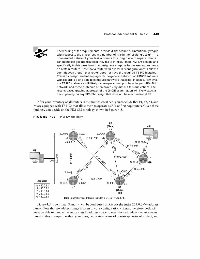
After your inventory of all routers in the multicast test bed, you conclude that r1, r2, r3, and r4 are equipped with TS PICs that allow them to operate as RPs or first hop routers. Given these findings, you decide on the PIM-SM topology shown in Figure 4.5.
F I G U R E 4 . 5 PIM-SM topology
Figure 4.5 shows that r3 and r4 will be configured as RPs for the entire 224.0.0.0/4 address range. Note that no address range is given in your configuration criteria; therefore both RPs must be able to handle the entire class D address space to meet the redundancy requirements posed in this example. Further, your design indicates the use of bootstrap protocol to elect, and
Note: Tunnel Services PICs are installed in r1,r2,r3,and r4.
M5M5
M5M5
M5M5
M5M5
fe-0/0/1fe-0/0/0
r1
r2
r3
fe-0/0/3
fe-0/0/0 fe-0/0/1 fe-0/0/1
fe-0/0/2
10.0
.5/2
4
10.0
.4.4
/30
fe-0/0/3
fe-0/0/010.0.4.12/30
10.0.2.4/30
10.0.2.0/30
10.0.2.8/30
so-0/
1/1so-0/1/0
so-0/1/0
at-0/1/0
at-0/2/1
.1 .14 .13
.9
.1
.1.5
.18
.2 .10 .910.0.4.8/30
10.0.4.16/30
fe-0/0
/1
fe-0/0
/2 10.0.
4.0/30
fe-0/0/2.2 .17
.6 .10
.2.5
r4
RP(224/4)
BSR
RP(224/4)
BSR
.6
so-0/2/0
M5M5
.1
.2fe
-0/0
/3172.16.30/24
r5
Loopbacks
r1 = 10.0.6.1r2 = 10.0.6.2r3 = 10.0.3.3r4 = 10.0.3.4r5 = 10.0.3.5
.200
MS1
MR1

444 Chapter 4 � Multicast
then communicate, RP information to the remaining nodes; note that Auto-RP is prohibited in this case by the stipulation that you run sparse mode only on all interfaces. You must configure at least two bootstrap capable routers to avoid a single point of failure with regard to RP election. In this example, r4 and r5 will both function as bootstrap routers (BSRs) to provide the required redundancy. Note that there is no need for a TS PIC in a BSR, and that a BSR can also be a candidate RP as is the case with r4 in this design.
You begin configuration on r3 with the following commands:
[edit protocols]
lab@r3# set pim interface all mode sparse
[edit protocols]
lab@r3# set pim interface fxp0 disable
Note that you have configured PIM sparse mode only and that the OoB interface is once again excluded from running PIM. The next command configures r3’s local RP properties:
[edit protocols]
lab@r3# set pim rp local address 10.0.3.3
It is customary to use the router’s lo0 address as the RP address for added robustness in the face of interface failures. The completed PIM stanza is displayed at r3:
[edit protocols]
lab@r3# show pim
rp {
local {
address 10.0.3.3;
}
}
interface all {
mode sparse;
}
interface fxp0.0 {
disable;
}
The PIM configuration for r4 is similar, and is shown here:
[edit protocols pim]
lab@r4# show
rp {
bootstrap-priority 10;
local {
address 10.0.3.4;
}
}

Protocol Independent Multicast 445
interface all {
mode sparse;
}
interface fxp0.0 {
disable;
}
A key difference in r4’s configuration is the presence of a bootstrap priority. The non-zero setting makes r4 a BSR candidate. Recall that the BSR functions to build, and then disseminate, a list of candidate RPs for advertised groups ranges. Each router then runs a hashing algorithm that results in all routers selecting the same candidate RP for a given range of group addresses. r4 is also configured to function as an RP for the 224/4 group range. The PIM-SM configu-ration of r5 is displayed:
[edit]
lab@r5# show protocols pim
rp {
bootstrap-priority 10;
}
interface all {
mode sparse;
}
interface fxp0.0 {
disable;
}
Note that r5 is not configured with local RP parameters, which is in keeping with the PIM-SM design shown earlier in Figure 4.5. r5 is configured with a non-zero bootstrap priority, thus allowing it to function as a BSR as needed. The PIM-SM configuration of r1 and r2 are virtually identical. r1’s configuration is shown next:
[edit]
lab@r1# show protocols pim
interface all {
mode sparse;
}
interface fxp0.0 {
disable;
}
Note that r1 and r2 are not configured to function as a BSR or RP. Be sure that you commit all your PIM-related changes before proceeding to the verification section.
Verifying PIM Sparse Mode
The verification of the PIM-SM control plane follows the general approach demonstrated for PIM-DM; specifically, you need to verify that PIM is enabled on the correct interfaces in the

446 Chapter 4 � Multicast
correct mode, that PIM neighbor discovery is functioning correctly, and that RPF checks through the inet.0 routing table are working. In addition, you need to confirm that bootstrap-based BSR election and RP selection are working properly. You begin with the determination of PIM interface status at r3:
[edit]
lab@r3# run show pim interfaces
Instance: PIM.master
Name Stat Mode IP V State Count DR address
at-0/1/0.0 Up Sparse 4 2 P2P 1
fe-0/0/0.0 Up Sparse 4 2 DR 1 10.0.4.13
fe-0/0/1.0 Up Sparse 4 2 NotDR 1 10.0.4.2
fe-0/0/2.0 Up Sparse 4 2 DR 0 172.16.0.13
fe-0/0/3.0 Up Sparse 4 2 DR 0 10.0.2.14
lo0.0 Up Sparse 4 2 DR 0 10.0.3.3
pd-0/3/0.32768 Up Sparse 4 2 P2P 0
pe-0/3/0.32770 Up Sparse 4 2 P2P 0
so-0/2/0.100 Up Sparse 4 2 P2P 1
The PIM interface display confirms that r3 is running PIM in sparse mode only on all expected interfaces. The added highlights call out the effects of the TS PIC, in that PIM Encap-sulation (pe) and PIM De-capsulation (pd) interfaces have automatically been created by the PIM entity on r3. Note that explicit configuration is not necessary to support PIM register encapsulation. The pe and pd interfaces are created automatically based on the presence of a TS PIC and related PIM configuration. You move on to the verification of PIM neighbor status, again on r3:
[edit]
lab@r3# run show pim neighbors
Instance: PIM.master
Interface IP V Mode Option Uptime Neighbor addr
at-0/1/0.0 4 2 HPL 00:55:37 10.0.2.1
fe-0/0/0.0 4 2 HPL 01:10:26 10.0.4.14
fe-0/0/1.0 4 2 HPL 01:10:26 10.0.4.2
so-0/2/0.100 4 2 HPL 01:10:26 10.0.2.6
The display confirms that r3 has detected four PIM neighbors, which is in keeping with the current multicast test bed topology. A quick RPF check at r5 proves that PIM-SM is using the inet.0 routing table for RPF checks:
[edit]
lab@r5# run show multicast rpf 10.0.5/24

Protocol Independent Multicast 447
Multicast RPF table: inet.0, 25 entries
10.0.5.0/24
Protocol: IS-IS
Interface: so-0/1/0.0
Neighbor: 10.0.2.10
Your next verification task is to confirm proper BSR election. You begin at r5:
[edit]
lab@r5# run show pim bootstrap
Instance: PIM.master
BSR Pri Local address Pri State Timeout
10.0.3.5 10 10.0.3.5 10 Elected 22
The output shows that r5 has elected itself as the PIM domain’s BSR, as denoted by the BSR and local addresses being the same. The router’s modified priority setting is also shown. The display at r5 provides a nice contrast when compared to that obtained at r3:
[edit]
lab@r3# run show pim bootstrap
Instance: PIM.master
BSR Pri Local address Pri State Timeout
10.0.3.5 10 10.0.3.3 0 InEligible 118
This output confirms that r3 is not BSR eligible due to its default priority setting. A similar bootstrap status is also seen on r1 and r2 (not shown). The BSR status of r4 is now checked:
[edit]
lab@r4# run show pim bootstrap
Instance: PIM.master
BSR Pri Local address Pri State Timeout
10.0.3.5 10 10.0.3.4 10 Candidate 122
The output from r4 shows that r5 has won the BSR contention process while also confirming that r4 is a candidate BSR due to its non-zero priority setting. Because r4 and r5 have the same BSR priority, the election’s outcome was determined by an IP address comparison that has the highest address taking all. With BSR election confirmed, you move on to the verification of RP election, this time starting at r4:
[edit]
lab@r4# run show pim rps
Instance: PIM.master
Family: INET

448 Chapter 4 � Multicast
RP address Type Holdtime Timeout Active groups Group prefixes
10.0.3.3 bootstrap 150 103 0 224.0.0.0/4
10.0.3.4 bootstrap 150 103 0 224.0.0.0/4
10.0.3.4 static 0 None 0 224.0.0.0/4
Family: INET6
RP address Type Holdtime Timeout Active groups Group prefixes
The highlights call out that r4 has learned its own RP address through local (static) assignment, as well as from the bootstrap protocol. Also of note is that r4 has learned of r3’s RP capability through the bootstrap protocol. Though not shown, a similar display is seen on r5. Because proper PIM-SM operation is contingent on all routers electing the same RP for a given group range, it is well worth the time to confirm that all routers in the multicast test bed are displaying both candi-date RPs. r1 has the expected RP display, given the current configuration in the multicast test bed:
[edit]
lab@r1# run show pim rps
Instance: PIM.master
Family: INET
RP address Type Holdtime Timeout Active groups Group prefixes
10.0.3.3 bootstrap 150 149 0 224.0.0.0/4
10.0.3.4 bootstrap 150 149 0 224.0.0.0/4
Family: INET6
RP address Type Holdtime Timeout Active groups Group prefixes
In stark contrast, r2 does not return the expected RP election results:
[edit protocols pim]
lab@r2# run show pim rps
Instance: PIM.master
Family: INET
RP address Type Holdtime Timeout Active groups Group prefixes
Family: INET6
RP address Type Holdtime Timeout Active groups Group prefixes
[edit protocols pim]
lab@r2#
The output from r2 indicates that there is a problem in your PIM-SM network as it has failed to detect either of the two RP candidates. You should resolve this issue before proceeding.

Protocol Independent Multicast 449
Troubleshooting a PIM-SM RP Election Problem
The displays shown in this section indicate that r2 is the only router in the test bed that has not successfully detected the presence of one or more RPs. While various approaches might be taken to troubleshoot this problem, this author believes that PIM tracing is often a good way to start. The tracing configuration shown here is committed on r2:
[edit]lab@r2# show protocols pimtraceoptions { file pim; flag general detail; flag hello detail; flag rp detail;}interface all { mode dense;}interface fxp0.0 { disable;}
Note that the rp flag is invaluable when you are concerned about either Auto-RP or bootstrap-related problems. After the tracing changes are committed, you observe the output shown next:
[edit]lab@r2# run monitor start pim
lab@r2#Apr 4 02:19:15 CHANGE 224.0.1.24.10.0.5.200/64 PIM pref 105/0 metric <Delete Int>Apr 4 02:19:15 rt_close: 1 route proto PIM.masterApr 4 02:19:15Apr 4 02:19:16 PIM fe-0/0/0.0 RECV 172.16.30.1 -> 224.0.0.13 V2 Bootstrap sum 0x55a0 len 46Apr 4 02:19:16 PIM Bootstrap not enabled on fe-0/0/0.0Apr 4 02:19:16 PIM fe-0/0/1.0 RECV 10.0.4.9 -> 224.0.0.13 V2 Bootstrap sum 0x2341 len 46Apr 4 02:19:16 PIM Bootstrap not enabled on fe-0/0/1.0Apr 4 02:19:16 PIM fe-0/0/2.0 RECV 10.0.4.1 -> 224.0.0.13 V2 Bootstrap sum 0xcc3f len 46Apr 4 02:19:16 PIM Bootstrap not enabled on fe-0/0/2.0Apr 4 02:19:16 PIM fe-0/0/0.0 RECV 10.0.5.1 -> 224.0.0.13 V2 Bootstrap sum 0x66cd len 46Apr 4 02:19:16 PIM Bootstrap not enabled on fe-0/0/0.0Apr 4 02:19:16 PIM fe-0/0/3.0 RECV 10.0.4.5 -> 224.0.0.13 V2 Bootstrap sum 0x66cd len 46Apr 4 02:19:16 PIM Bootstrap not enabled on fe-0/0/3.0Apr 4 02:19:17 PIM fe-0/0/3.0 SENT 10.0.4.6 -> 224.0.0.13 V2 Hello hold 105 T-bit LAN prune 500 ms override 2000 ms pri 1 sum 0x55b1 len 26
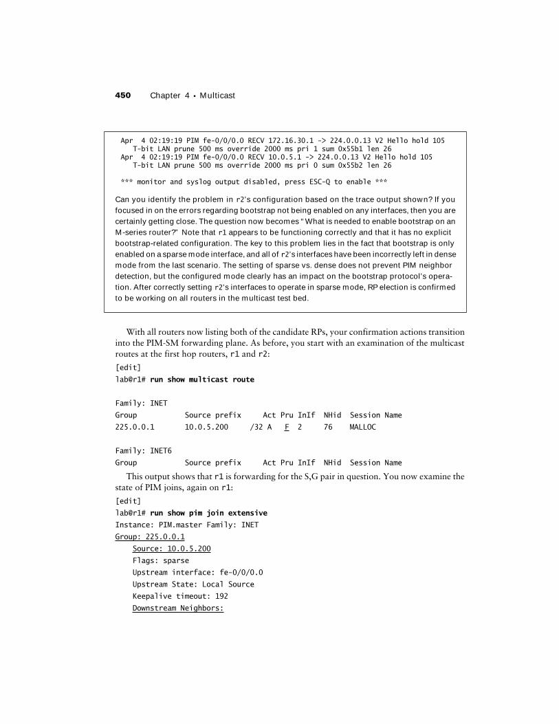
450 Chapter 4 � Multicast
With all routers now listing both of the candidate RPs, your confirmation actions transition into the PIM-SM forwarding plane. As before, you start with an examination of the multicast routes at the first hop routers, r1 and r2:
[edit]
lab@r1# run show multicast route
Family: INET
Group Source prefix Act Pru InIf NHid Session Name
225.0.0.1 10.0.5.200 /32 A F 2 76 MALLOC
Family: INET6
Group Source prefix Act Pru InIf NHid Session Name
This output shows that r1 is forwarding for the S,G pair in question. You now examine the state of PIM joins, again on r1:
[edit]
lab@r1# run show pim join extensive
Instance: PIM.master Family: INET
Group: 225.0.0.1
Source: 10.0.5.200
Flags: sparse
Upstream interface: fe-0/0/0.0
Upstream State: Local Source
Keepalive timeout: 192
Downstream Neighbors:
Apr 4 02:19:19 PIM fe-0/0/0.0 RECV 172.16.30.1 -> 224.0.0.13 V2 Hello hold 105 T-bit LAN prune 500 ms override 2000 ms pri 1 sum 0x55b1 len 26Apr 4 02:19:19 PIM fe-0/0/0.0 RECV 10.0.5.1 -> 224.0.0.13 V2 Hello hold 105 T-bit LAN prune 500 ms override 2000 ms pri 0 sum 0x55b2 len 26
*** monitor and syslog output disabled, press ESC-Q to enable ***
Can you identify the problem in r2’s configuration based on the trace output shown? If you focused in on the errors regarding bootstrap not being enabled on any interfaces, then you are certainly getting close. The question now becomes “What is needed to enable bootstrap on an M-series router?” Note that r1 appears to be functioning correctly and that it has no explicit bootstrap-related configuration. The key to this problem lies in the fact that bootstrap is only enabled on a sparse mode interface, and all of r2’s interfaces have been incorrectly left in dense mode from the last scenario. The setting of sparse vs. dense does not prevent PIM neighbor detection, but the configured mode clearly has an impact on the bootstrap protocol’s opera-tion. After correctly setting r2’s interfaces to operate in sparse mode, RP election is confirmed to be working on all routers in the multicast test bed.

Protocol Independent Multicast 451
Interface: fe-0/0/3.0
10.0.4.17 State: Join Flags: S Timeout: 159
Instance: PIM.master Family: INET6
The various highlights in the capture confirm that r1 has established a SPT for 10.0.5.200, 225.0.0.1, and that it has pruned itself from the RPT-based tree. This is indicated by the lack of a ∗,G entry and the presence of a S,G entry. Recall that forwarding over the RPT tree is short-lived, in that once a receiver detects multicast traffic from source “S” via the shared tree it initiates a S,G join to effect a shortest path tree between that source and its local receivers. It is noted that at this time r2 has pruned this multicast route:
[edit]
lab@r2# run show multicast route
Family: INET
Group Source prefix Act Pru InIf NHid Session Name
225.0.0.1 10.0.5.200 /32 A P 2 0 MALLOC
Family: INET6
Group Source prefix Act Pru InIf NHid Session Name
The pruned state is reflected in the downstream interfaces listed in the output of a PIM join at r2:
[edit]
lab@r2# run show pim join extensive
Instance: PIM.master Family: INET
Group: 225.0.0.1
Source: 10.0.5.200
Flags: sparse
Upstream interface: fe-0/0/0.0
Upstream State: Local Source
Keepalive timeout: 153
Downstream Neighbors:
Instance: PIM.master Family: INET6
The next step in the verification of the PIM-SM data plane takes you to r4 because previous output from r1 indicated that its fe-0/0/3 interface is downstream for the S,G entry being tracked:
[edit]
lab@r4# run show pim join extensive
Instance: PIM.master Family: INET
Group: 225.0.0.1
Source: 10.0.5.200
Flags: sparse

452 Chapter 4 � Multicast
Upstream interface: fe-0/0/2.0
Upstream State: Join to Source
Keepalive timeout: 158
Downstream Neighbors:
Interface: so-0/1/1.0
10.0.2.9 State: Join Flags: S Timeout: 160
Instance: PIM.master Family: INET6
As with r1, r4’s display confirms that S,G state has been correctly established. The indication that r4’s so-0/1/1 interface is downstream tells you that the S,G multicast traffic should be flowing from r4 to r5 over the POS link. Note that r4 does not show a ∗,G join. This is because it has no local group membership to trigger a join to the shared tree. In contrast, the static joins on r5 have resulted in joins to both the shared and shortest path trees:
[edit]
lab@r5# run show pim join extensive
Instance: PIM.master Family: INET
Group: 225.0.0.1
Source: *
RP: 10.0.3.3
Flags: sparse,rptree,wildcard
Upstream interface: at-0/2/1.0
Upstream State: Join to RP
Downstream Neighbors:
Interface: fe-0/0/3.0
172.16.30.1 State: Join Flags: SRW Timeout: Infinity
Group: 225.0.0.1
Source: 10.0.5.200
Flags: sparse,spt
Upstream interface: so-0/1/0.0
Upstream State: Join to Source, Prune to RP
Keepalive timeout: 209
Downstream Neighbors:
Interface: fe-0/0/3.0
172.16.30.1 State: Join Flags: S Timeout: Infinity
The static group membership definitions on r5 result in a rather long timeout on the PIM Joins (Infinity). Also of note is the presence of both a ∗,G and S,G join at r5. The capture shows that the bootstrap hashing function has resulted in the selection of 10.0.3.3 as the RP for the 225.0.0.1 group. It bears stressing that the bootstrap mechanism provides inherent load balancing

Protocol Independent Multicast 453
among a set of candidate RPs. The result is that you are likely to find that r5 has selected 10.0.3.4 as the RP for a different group address.
The presence of a SPT for the S,G pair associated with MS1 and the 225.0.0.1 group proves that the PIM RP and register functionality must have worked, because without these functions there would have been no way for MR1 to discover MS1, and therefore the establishment of the SPT shown would not have been possible. The following capture shows the PIM join state for r3:
[edit]
lab@r3# run show pim join extensive
Instance: PIM.master Family: INET
Group: 225.0.0.1
Source: *
RP: 10.0.3.3
Flags: sparse,rptree,wildcard
Upstream interface: local
Upstream State: Local RP
Downstream Neighbors:
Interface: at-0/1/0.0
10.0.2.1 State: Join Flags: SRW Timeout: 193
Group: 225.0.0.1
Source: 10.0.5.200
RP: 10.0.3.3
Flags: sparse,rptree
Upstream interface: local
Upstream State: Local RP
Keepalive timeout:
Downstream Neighbors:
Interface: at-0/1/0.0 (pruned)
10.0.2.1 State: Prune Flags: SR Timeout: 193
It is interesting to note that r3 has pruned itself from the S,G SPT, and that it confirms it is the RP for ∗, 225.0.0.1 by virtue of the Local RP designation for the ∗,G entry’s upstream state. The results seen thus far confirm that PIM SM is operating in accordance with all provided criteria. Before leaving this section, you decide to test RP failover by deactivating PIM functionality on r3, which is the current RP for the ∗,G being discussed:
[edit]
lab@r3# deactivate protocols pim
[edit]
lab@r3# commit
commit complete

454 Chapter 4 � Multicast
Because it can take a while for multicast protocols and state to reform, you decide to wait a few moments before analyzing the results. A few minutes later, proper RP failover, and continued PIM-SM data forwarding, are confirmed at r5:
[edit]
lab@r5# run show pim rps
Instance: PIM.master
Family: INET
RP address Type Holdtime Timeout Active groups Group prefixes
10.0.3.4 bootstrap 150 119 2 224.0.0.0/4
Family: INET6
RP address Type Holdtime Timeout Active groups Group prefixes
The loss of r3 has not left the PIM domain without an RP, which is in keeping with the requirements that there be no single point of RP failure in your design. Data forwarding is again confirmed in the face of r3’s recently deactivated PIM stanza:
[edit]
lab@r5# run show pim join extensive
Instance: PIM.master Family: INET
Group: 225.0.0.1
Source: *
RP: 10.0.3.4
Flags: sparse,rptree,wildcard
Upstream interface: so-0/1/0.0
Upstream State: Join to RP
Downstream Neighbors:
Interface: fe-0/0/3.0
172.16.30.1 State: Join Flags: SRW Timeout: Infinity
Group: 225.0.0.1
Source: 10.0.5.200
Flags: sparse
Upstream interface: so-0/1/0.0
Upstream State: Join to Source
Keepalive timeout: 209
Downstream Neighbors:
Interface: fe-0/0/3.0
172.16.30.1 State: Join Flags: S Timeout: Infinity
The PIM join display confirms that r5 has now mapped the 225.0.0.1 group address to the domain’s remaining RP, and that a S,G join is still in effect. This behavior validates the

Protocol Independent Multicast 455
redundancy aspects of your PIM design. Before proceeding to the next section, it is suggested that you reactivate r3’s PIM configuration:
[edit]
lab@r3# rollback 1
load complete
[edit]
lab@r3# commit
commit complete
Configuring PIM-SM Using Auto-RP
To complete this scenario, you must reconfigure the multicast test bed according to the following criteria:� Replace the current bootstrap based election with Auto-RP.� Ensure that there is no single point of RP failure.� Multicast traffic from MS1 to MR1 must be delivered to MR1.
Refer back to Figure 4.2 as needed for the details of the multicast topology that you are working with.
The goal of this configuration exercise is to convert the existing network from the use of bootstrap to Auto-RP based RP election. Note that your network must continue to provide RP redundancy, which leads you to the Auto-RP design shown in Figure 4.6.
F I G U R E 4 . 6 Auto-RP topology
Note: Tunnel Services PICs are installed in r1,r2,r3,and r4.
M5M5
M5M5
M5M5
M5M5
fe-0/0/1fe-0/0/0
r1
r2
r3
fe-0/0/3
fe-0/0/0 fe-0/0/1
Discovery
Discovery
fe-0/0/1
fe-0/0/2
10.0
.5/2
4
10.0
.4.4
/30
fe-0/0/3
fe-0/0/010.0.4.12/30
10.0.2.4/30
10.0.2.0/30
10.0.2.8/30
so-0/
1/1so-0/1/0
so-0/1/0
at-0/1/0
at-0/2/1
.1 .14 .13
.9
.1
.1.5
.18
.2 .10 .910.0.4.8/30
10.0.4.16/30
fe-0/0
/1
fe-0/0
/2 10.0.
4.0/30
fe-0/0/2.2 .17
.6 .10
.2.5
r4
RP(224/4)
Mapping
RP(224/4)
Announce
Mapping
.6
so-0/2/0
M5M5
.1
.2
fe-0
/0/3
172.16.30/24
r5
Loopbacks
r1 = 10.0.6.1r2 = 10.0.6.2r3 = 10.0.3.3r4 = 10.0.3.4r5 = 10.0.3.5
.200
MS1
MR1

456 Chapter 4 � Multicast
Your PIM-SM Auto-RP design once again presses r3 and r4 into the role of RP for the entire 224/4 group range. To provide the required redundancy, you must ensure that your network has at least two candidate RPs, and at least two mapping agents. In this example, r4 and r5 are configured as Auto-RP mapping agents. Once again your design has r4 functioning in a dual capacity; this time as a candidate RP and as an Auto-RP mapping agent. Note that an Auto-RP mapping agent router also generates announce messages when it is RP capable, and that it also listens to discovery messages to learn RP mapping results. When multiple mapping agents are present, each mapping agent operates independently; coordination between mapping agents is not required because all mapping agents compute the same mapping results, which is in keeping with their ability to operate independently.
r3 is configured with the announce option to ensure that it announces its local RP capabilities while also listening to Auto-RP mapping messages generated by the mapping agent. Because r1 and r2 are not configured as RPs, they will be configured to operate in discovery mode, which is the most basic Auto-RP option. In this mode, the routers will only listen for mapping mes-sages to learn the results of RP-to-group range mappings.
The Auto-RP options of discovery, announce, and mapping each build on the previous option’s functionality. In other words, discovery listens to mapping messages only while the announce options listens to mapping messages while also generating announce messages. It is common practice in the “real world” to just set all routers to the highest level of functionality (mapping) and then let their individual configurations determine if this level of functionality is actually used. For example, the lack of local RP settings will prevent a mapping router from generating announce messages, although the capability is inherent in its mapping setting. Because an examination may be written to test the candidate’s understanding of each option, you may be expected to configure only the func-tionality that is actually required, which is the approach taken here. The moral here is that over-configuring a network is not necessarily bad, unless, of course, your rules of engagement restrict such over-configuration.
Note that Auto-RP requires the use of dense mode flooding to support announce messages (224.0.1.39) and discovery messages (224.0.1.40). Further, proper Auto-RP operation also requires that the router’s lo0 interface be assigned a routable IP address and that you configure the lo0 interface as a sparse-dense PIM interface.
Your Auto-RP configuration scenario starts with the removal of any bootstrap-related configuration from r5 and r4:
[edit protocols]
lab@r3# delete pim rp bootstrap-priority
The Auto-RP configuration starts at r4 with the setting of sparse-dense mode on all PIM interfaces. This mode is needed to support dense-mode flooding of Auto-RP discovery and mapping messages while still operating in sparse mode for all other groups:
[edit protocols pim]
lab@r4# set interface all mode sparse-dense

Protocol Independent Multicast 457
The required dense mode groups are now defined.
[edit protocols pim]
lab@r4# set dense-groups 224.0.1.39
[edit protocols pim]
lab@r4# set dense-groups 224.0.1.40
In case you are one of those types that has not yet committed Auto-RP’s dense mode groups to memory, do not despair! When taking the JNCIE examination, you will have access to the JUNOS software documentation for the software release used in the JNCIE lab, and happily, the dense mode groups needed for Auto-RP operation are clearly identified in the documenta-tion set. Even better, the answer is also found with the JUNOS software Online Documentation:
[edit protocols pim]
lab@r4# run help topic pim auto-rp | match dense
dense mode PIM to advertise control traffic, it provides an important
If PIM is operating in sparse or sparse-dense mode, configure how the
you must enable PIM sparse-dense mode on the lo0.0 interface.
address 127.0.0.1. Also, you must enable PIM sparse-dense mode on the
1. Use the mode statement and specify the option sparse-dense
dense mode for others. The default is to operate in sparse mode unless
the router is specifically informed of a dense mode group.
2. Configure two multicast dense groups (224.0.1.39 and
224.0.1.40) using the dense-groups statement at the [edit
occurs through a PIM dense mode model where group 224.0.1.39 is used for
To configure auto-RP, include the mode, dense-groups, and auto-rp
dense-groups {
mode sparse-dense;
Although the prose is a bit messy after being munged by the CLI’s match function, the high-lights call out the exact information being sought, most likely faster than this information could have been retrieved in any other way! The final command at r4 enables Auto-RP mapping functionality:
[edit protocols pim]
lab@r4# set rp auto-rp mapping
The modified PIM stanza is shown next with added highlights:
[edit protocols pim]
lab@r4# show
dense-groups {
224.0.1.39/32;
224.0.1.40/32;
}
rp {

458 Chapter 4 � Multicast
local {
address 10.0.3.4;
}
auto-rp mapping;
}
interface all {
mode sparse-dense;
}
interface fxp0.0 {
disable;
}
The configuration of r3 is similar, with the primary exception being the use of the announce option:
[edit protocols pim]
lab@r3# show
dense-groups {
224.0.1.39/32;
224.0.1.40/32;
}
rp {
local {
address 10.0.3.3;
}
auto-rp announce;
}
interface all {
mode sparse-dense;
}
interface fxp0.0 {
disable;
}
The modified PIM stanza for r5 enables Auto-RP mapping functions; note the absence of local RP configuration on r5:
[edit]
lab@r5# show protocols pim
dense-groups {
224.0.1.39/32;
224.0.1.40/32;
}
rp {
auto-rp mapping;
}

Protocol Independent Multicast 459
interface all {
mode sparse-dense;
}
interface fxp0.0 {
disable;
}
Although only shown here for r2, the PIM configuration of r1 is virtually identical. Note that these routers are set to perform Auto-RP discovery functions only:
[edit protocols pim]
lab@r2# show
dense-groups {
224.0.1.39/32;
224.0.1.40/32;
}
rp {
auto-rp discovery;
}
interface all {
mode sparse-dense;
}
interface fxp0.0 {
disable;
}
Make sure that all modifications are committed before you proceed to the confirmation section.
Verifying PIM Sparse Mode Using Auto-RP
Because the only changes made to the test bed relate to the use of Auto-RP instead of the bootstrap protocol, the confirmation steps in this section will be confined to the verification of RP election. You begin with the confirmation of sparse-dense mode operation on all PIM interfaces:
[edit protocols pim]
lab@r3# run show pim interfaces
Instance: PIM.master
Name Stat Mode IP V State Count DR address
at-0/1/0.0 Up SparseDense 4 2 P2P 1
fe-0/0/0.0 Up SparseDense 4 2 NotDR 1 10.0.4.14
fe-0/0/1.0 Up SparseDense 4 2 NotDR 1 10.0.4.2
fe-0/0/2.0 Up SparseDense 4 2 DR 0 172.16.0.13
fe-0/0/3.0 Up SparseDense 4 2 DR 0 10.0.2.14
lo0.0 Up SparseDense 4 2 DR 0 10.0.3.3
pd-0/3/0.32768 Up Sparse 4 2 P2P 0
pe-0/3/0.32770 Up Sparse 4 2 P2P 0

460 Chapter 4 � Multicast
The PIM interface display confirms that r3 is correctly configured to run sparse-dense mode. Next, you verify that an RP has been successfully elected via the Auto-RP mechanism:
[edit protocols pim]
lab@r3# run show pim rps
Instance: PIM.master
Family: INET
RP address Type Holdtime Timeout Active groups Group prefixes
10.0.3.4 auto-rp 150 101 0 224.0.0.0/4
10.0.3.3 static 0 None 0 224.0.0.0/4
Family: INET6
RP address Type Holdtime Timeout Active groups Group prefixes
The output confirms that r3 is locally configured as an RP (static) and that it has learned of the 10.0.3.4 RP through the Auto-RP protocol. Similar confirmation of proper Auto-RP operation is also seen in the display obtained from r1:
[edit]
lab@r1# run show pim rps
Instance: PIM.master
Family: INET
RP address Type Holdtime Timeout Active groups Group prefixes
10.0.3.4 auto-rp 150 124 0 224.0.0.0/4
Family: INET6
RP address Type Holdtime Timeout Active groups Group prefixes
Note that both r1 and r3 display the same RP as learned through Auto-RP; it is critical that the results of the Auto-RP mapping function yield a consistent choice of RP-to-group mappings for all routers in the PIM domain. Though not shown, you may assume that all five routers are correctly displaying r4 (10.0.3.4) as the RP. It is interesting to note that all routers have issued dense mode joins to the Auto-RP dense mode groups so that they will receive mapping and announce messages:
[edit]
lab@r5# run show pim join
Instance: PIM.master Family: INET
Group: 224.0.1.39
Source: 10.0.3.3
Flags: dense
Upstream interface: at-0/2/1.0

Protocol Independent Multicast 461
Group: 224.0.1.39
Source: 10.0.3.4
Flags: dense
Upstream interface: so-0/1/0.0
Group: 224.0.1.40
Source: 10.0.3.5
Flags: dense
Upstream interface: local
Group: 225.0.0.1
Source: *
RP: 10.0.3.4
Flags: sparse,rptree,wildcard
Upstream interface: so-0/1/0.0
Group: 225.0.0.1
Source: 10.0.5.200
Flags: sparse,spt
Upstream interface: at-0/2/1.0
Instance: PIM.master Family: INET6
With Auto-RP based RP election confirmed, you should again confirm the PIM-SM forwarding plane. The steps are not shown here because they are identical to those already demonstrated for both PIM-DM and PIM-SM. You may assume that multicast traffic is confirmed to be flowing from MS1 to MR1 over a SPT, as indicated by this capture from r3:
[edit protocols pim]
lab@r3# run show pim join extensive
Instance: PIM.master Family: INET
Group: 224.0.1.39
Source: 10.0.3.3
Flags: dense
Upstream interface: local
Downstream interfaces:
local
lo0.0
fe-0/0/0.0
fe-0/0/1.0
at-0/1/0.0
so-0/2/0.100
Group: 224.0.1.39
Source: 10.0.3.4

462 Chapter 4 � Multicast
Flags: dense
Upstream interface: so-0/2/0.100
Downstream interfaces:
local
lo0.0
fe-0/0/0.0
fe-0/0/1.0
at-0/1/0.0 (Pruned timeout 139)
Group: 224.0.1.40
Source: 10.0.3.5
Flags: dense
Upstream interface: at-0/1/0.0
Downstream interfaces:
local
lo0.0
fe-0/0/0.0
fe-0/0/1.0
so-0/2/0.100 (Pruned timeout 124)
Group: 225.0.0.1
Source: 10.0.5.200
Flags: sparse
Upstream interface: fe-0/0/1.0
Upstream State: Join to Source
Keepalive timeout: 208
Downstream Neighbors:
Interface: at-0/1/0.0
10.0.2.1 State: Join Flags: S Timeout: 159
Instance: PIM.master Family: INET6
Before leaving this section, you decide to test RP failover by deactivating PIM functionality on r4, which has been selected as the RP for the 224/4 range by the Auto-RP mapping function:
[edit]
lab@r4# deactivate protocols pim
[edit]
lab@r4# commit
commit complete

Protocol Independent Multicast 463
After waiting a few minutes, RP failover is confirmed at r2:
[edit protocols pim]
lab@r2# run show pim rps
Instance: PIM.master
Family: INET
RP address Type Holdtime Timeout Active groups Group prefixes
10.0.3.3 auto-rp 150 146 0 224.0.0.0/4
Family: INET6
RP address Type Holdtime Timeout Active groups Group prefixes
Make sure that you restore r4’s configuration after you are satisfied that all PIM redundancy requirements have been met:
[edit]
lab@r4# rollback 1
load complete
[edit]
lab@r4# commit
commit complete
PIM Tracing
As with all protocols, there may be times when you need to closely monitor the operation of PIM to diagnose problems or to better understand its operation. This section provides an example of PIM tracing in the context of the PIM-SM Auto-RP based topology that is currently in place. A typical PIM tracing configuration has been added to r3’s configuration:
[edit protocols pim]
lab@r3# show traceoptions
file pim;
flag rp detail;
flag hello detail;
flag register detail;
flag join detail;
A sample of the tracing output obtained with this configuration is shown next:
[edit protocols pim]
lab@r3# run monitor start pim
*** pim ***
Apr 4 20:52:39 PIM at-0/1/0.0 RECV 10.0.2.1 -> 224.0.0.13 V2 Hello hold 105
T-bit LAN prune 500 ms override 2000 ms pri 1 sum 0x55b1 len 26
lab@r3#

464 Chapter 4 � Multicast
Apr 4 20:52:41 PIM fe-0/0/1.0 SENT 10.0.4.1 -> 224.0.0.13 V2 JoinPrune to
10.0.4.2 holdtime 210 groups 1 sum 0xd61f len 34
Apr 4 20:52:41 group 225.0.0.1 joins 1 prunes 0
Apr 4 20:52:41 join list:
Apr 4 20:52:41 source 10.0.5.200 flags sparse
Apr 4 20:52:45 PIM fe-0/0/1.0 SENT 10.0.4.1 -> 224.0.0.13 V2 Hello hold 105
T-bit LAN prune 500 ms override 2000 ms pri 1 sum 0x55b1 len 26
Apr 4 20:52:55 PIM so-0/2/0.100 SENT 10.0.2.5 -> 224.0.0.13 V2 Hello hold 105
T-bit LAN prune 500 ms override 2000 ms pri 1 sum 0x55b1 len 26
. . .
Apr 4 20:53:09 PIM at-0/1/0.0 RECV 10.0.2.1 -> 224.0.0.13 V2 Hello hold 105
T-bit LAN prune 500 ms override 2000 ms pri 1 sum 0x55b1 len 26
Apr 4 20:53:12 PIM at-0/1/0.0 RECV 10.0.2.1 -> 224.0.0.13 V2 JoinPrune to
10.0.2.2 holdtime 210 groups 1 sum 0xd81f len 34
Apr 4 20:53:12 group 225.0.0.1 joins 1 prunes 0
Apr 4 20:53:12 join list:
Apr 4 20:53:12 source 10.0.5.200 flags sparse
Apr 4 20:53:12 PIM fe-0/0/1.0 SENT 10.0.4.1 -> 224.0.0.13 V2 Hello hold 105
T-bit LAN prune 500 ms override 2000 ms pri 1 sum 0x55b1 len 26
Apr 4 20:53:19 PIM SENT 10.0.3.3 -> 224.0.1.39+496 AutoRP v1 announce hold 150
rpcount 1 len 20 rp 10.0.3.3 version 2 groups 1 prefixes 224.0.0.0/4
Apr 4 20:53:19 PIM at-0/1/0.0 RECV 10.0.3.5+496 -> 224.0.1.40 AutoRP v1
mapping hold 150 rpcount 1 len 20 rp 10.0.3.4 version 2 groups 1 prefixes
224.0.0.0/4
. . .
Apr 4 20:53:37 PIM fe-0/0/1.0 SENT 10.0.4.1 -> 224.0.0.13 V2 JoinPrune to
10.0.4.2 holdtime 210 groups 1 sum 0xd61f len 34
Apr 4 20:53:37 group 225.0.0.1 joins 1 prunes 0
Apr 4 20:53:37 join list:
Apr 4 20:53:37 source 10.0.5.200 flags sparse
Apr 4 20:53:38 PIM at-0/1/0.0 RECV 10.0.2.1 -> 224.0.0.13 V2 Hello hold 105
T-bit LAN prune 500 ms override 2000 ms pri 1 sum 0x55b1 len 26
Apr 4 20:53:42 PIM fe-0/0/1.0 SENT 10.0.4.1 -> 224.0.0.13 V2 Hello hold 105
T-bit LAN prune 500 ms override 2000 ms pri 1 sum 0x55b1 len 26
The edited capture shows quite a few PIM hellos, a join message or two (recall that joins and prunes are sent periodically to maintain state), and the presence of Auto-RP announce and map-ping messages.
PIM Summary
This section presented several JNCIE-level multicast configuration scenarios based on PIM. Like DVMRP, enabling PIM on a multi-access interfaces automatically enables the IGMP

MSDP 465
protocol on that interface. Unlike DVMRP, PIM is not a routing protocol, and PIM does not require a special routing table for RPF checks. Many find that the absence of RIB group configuration makes PIM far easier to deal with when compared to DVMRP.
When operating in dense mode, PIM uses a flood-and-prune approach based on broadcast trees. PIM-DM does not require RPs, and therefore has no need for Bootstrap or Auto-RP func-tionality and no need for TS PIC hardware. In sparse mode, PIM requires that sources and receivers for a given multicast group agree upon a Rendezvous Point (RP) where initial contact is made. The RP can be statically defined, or can be dynamically learned using the bootstrap protocol (PIM version 2) or the Auto-RP mechanism (PIM versions 1 or 2). You can configure multiple RPs with either approach, but load balancing among a set of RPs is possible only with the bootstrap protocol (Any-Cast is covered in a later section). For BSR redundancy, ensure that you have at least two BSR candidates by setting a non-zero priority in these routers. For Auto-RP redundancy, you must ensure that at least two routers are capable of providing the mapping function. Recall that Auto-RP requires sparse-dense mode operation and the definition of the two dense groups associated with Auto-RP for proper operation.
It can take a few minutes for all routers to learn the domain’s RP, whether you use Auto-RP or bootstrap. Be sure that you give your network time to converge before making configuration changes or deciding to reboot, as these actions may only serve to prolong RP convergence.
MSDPThe Multicast Source Discovery Protocol (MSDP) is used to convey information about active multicast sources between autonomous systems in support of interdomain multicast. MSDP is also used within a single multicast domain to support Any-Cast RPs.
MSDP can work with or without MP-BGP. MP-BGP advertises multicast routes using Sub-AFI 2. These routes are automatically placed into the inet.2 routing table by JUNOS software. Placing multicast routes into a special routing table allows you to have a multicast for-warding topology that differs from the unicast forwarding topology for the same prefix. When MP-BGP is not configured, all routes are placed into the common inet.0 routing table, which forces a common forwarding topology for unicast and multicast traffic. Note that to actually achieve different forwarding topologies between autonomous domains, you must have multiple EBGP peering interfaces and you must configure your unicast and multicast EBGP peering sessions to use one, or the other, of these links.
The purpose of MSDP is to provide a mechanism by which active sources in one PIM domain are communicated to RPs in other domains. The knowledge of an active source for group G results in RPs with ∗,G join state generating S,G joins back toward the active source to establish a source-specific tree that spans domain boundaries.
Configure Any-Cast and MSDP
Any-Cast is a technique that allows load balancing among a set of RPs that are learned through the Auto-RP mechanism. Recall that normally Auto-RP selects a single RP from a set of

466 Chapter 4 � Multicast
candidate RPs that will handle all ∗,G traffic for the group range advertised. With Any-Cast, a set of RPs are deployed using a duplicated address, such that stations “see” a single RP and sim-ply direct their joins according to the metrically closest route to the “single” RP address. From the perspective of a multicast router, the failure of an Any-Cast RP will either go completely undetected, or manifest itself as a metric increase due to the need to begin directing joins and register messages to the next metrically closest RP.
Any-Cast makes use of MSDP to tie together the RPs that make up the Any-Cast RP, just as the MSDP protocol ties together two or more RPs that exist within independent routing domains.
To complete this section, you must alter your configurations to meet these criteria:� Use Auto-RP to elect two RPs for the group range 224.0.0.0 through 225.255.255.255.� Ensure that traffic for these group ranges can be balanced over both RPs.� Ensure that multicast traffic sent from MS1 is delivered to MR1.
The wording of your objectives does not specifically mention Any-Cast by design. The goal here is to verify that the candidate understands the limitations of Auto-RP, and that the Any-Cast approach is designed to overcome Auto-RP’s load-balancing shortcomings. Also note that MSDP is not mentioned anywhere in your list of objectives. Without MSDP, you will likely find that traffic will not flow correctly from MS1 to MR1, because the source may send its register messages to one RP while the receiver sends its join to the other. Figure 4.7 documents the Any-Cast design that you have decided on, given the current test bed’s configuration and your new configuration objectives.
F I G U R E 4 . 7 Any-Cast topology
Note: Tunnel Services PICs are installed in r1,r2,r3,and r4.
M5M5
M5M5
M5M5
M5M5
fe-0/0/1fe-0/0/0
r1
r2
r3
fe-0/0/3
fe-0/0/0 fe-0/0/1
Discovery
Discovery
RP(224/7)
Announce
fe-0/0/1
fe-0/0/2
10.0
.5/2
4
10.0
.4.4
/30
fe-0/0/3
fe-0/0/010.0.4.12/30
10.0.2.4/30
10.0.2.0/30
10.0.2.8/30
so-0/
1/1so-0/1/0
so-0/1/0
at-0/1/0
at-0/2/1
.1 .14 .13
.9
.1
.1.5
.18
.2 .10 .910.0.4.8/30
10.0.4.16/30
fe-0/0
/1
fe-0/0
/2 10.0.
4.0/30
fe-0/0/2.2 .17
.6 .10
.2.5
r4
Loopbacks
RP(224/7)
Mapping
Mapping
.6
so-0/2/0
M5M5
.1
.2
fe-0
/0/3
172.16.30/24
r5
r4 = 10.0.3.4
r1 = 10.0.6.1r2 = 10.0.6.2r3 = 10.0.3.3
10.0.3.34
r5 = 10.0.3.510.0.3.34
.200
MS1
MR1

MSDP 467
Note that the Any-Cast topology tries to leave as much functionality and configuration in place from the previous PIM-SM Auto-RP scenario as practical. A key addition to Figure 4.7 is your choice of the non-unique lo0 address that will be used by your RPs, and the new group assignment that reflects the group range restrictions posed in this scenario.
You start your Any-Cast configuration on r3 with the assignment of the non-unique lo0 address that will be shared by all RPs:
[edit interfaces]
lab@r3# set lo0 unit 0 family inet address 10.0.3.3/32 primary
[edit interfaces]
lab@r3# set lo0 unit 0 family inet address 10.0.3.34
Note that the existing (and unique) lo0 address is tagged with the primary keyword to ensure that the new, non-unique address cannot become the router’s primary address (because this will change the router’s ID and could cause a host of other problems, considering its non-unique nature). The primary tag is not strictly needed here because the default behavior makes the numerically lowest value the primary address for the interface, but being safe is never a bad idea. The added safety net makes inclusion of the primary keyword highly recommended. The following commands redefine the router’s local RP properties in accordance with the require-ments of this scenario:
[edit protocols pim]
lab@r3# set rp local address 10.0.3.34 group-ranges 224/7
Note that the local RP is defined to use the non-unique address that was assigned to r3’s lo0 interface in the previous step. The last set of commands configures the MSDP peering session between r3 and r4:
[edit protocols msdp]
lab@r3# set group as-65412 peer 10.0.3.4
[edit protocols msdp]
lab@r3# set group as-65412 local-address 10.0.3.3
Note that the MSDP peering session must be established to the unique lo0 address at the remote router. The source-address statement is mandatory for MSDP; specifying the unique lo0 address as the source of MSDP packets is important because the remote router expects to peer with this address. The changes to r3’s configuration in support of Any-Cast RP are displayed next with added highlights:
[edit]
lab@r3# show protocols msdp
group as-65412 {
local-address 10.0.3.3;
peer 10.0.3.4;
}

468 Chapter 4 � Multicast
[edit]
lab@r3# show protocols pim
traceoptions {
file pim;
flag rp detail;
flag hello detail;
flag register detail;
flag join detail;
}
dense-groups {
224.0.1.39/32;
224.0.1.40/32;
}
rp {
local {
address 10.0.3.34;
group-ranges {
224.0.0.0/7;
}
}
auto-rp announce;
}
interface all {
mode sparse-dense;
}
interface fxp0.0 {
disable;
}
[edit]
lab@r3# show interfaces lo0
unit 0 {
family inet {
address 10.0.3.3/32 {
primary;
}
address 10.0.3.34/32;
}
family iso {
address 49.0001.3333.3333.3333.00;
}
}

MSDP 469
Note that the majority of r3’s PIM configuration remains in effect from the previous section covering Auto-RP. Similar changes are now made to r4. These changes are displayed here with highlights:
[edit]
lab@r4# show protocols msdp
group as-65412 {
local-address 10.0.3.4;
peer 10.0.3.3;
}
[edit]
lab@r4# show protocols pim
dense-groups {
224.0.1.39/32;
224.0.1.40/32;
}
rp {
local {
address 10.0.3.34;
group-ranges {
224.0.0.0/7;
}
}
auto-rp mapping;
}
interface all {
mode sparse-dense;
}
interface fxp0.0 {
disable;
}
[edit]
lab@r4# show interfaces lo0
unit 0 {
family inet {
address 10.0.3.4/32 {
primary;
}
address 10.0.3.34/32;
}

470 Chapter 4 � Multicast
family iso {
address 49.0001.4444.4444.4444.00;
}
}
Be sure to commit all your changes before proceeding to the verification section.
Verifying Any-Cast and MSDP
Verification of Any-Cast operation begins with confirmation that all routers now display a single RP that is associated with the non-unique address chosen for your Auto-RP:
[edit]
lab@r3# run show pim rps
Instance: PIM.master
Family: INET
RP address Type Holdtime Timeout Active groups Group prefixes
10.0.3.34 auto-rp 150 138 1 224.0.0.0/7
10.0.3.34 static 0 None 1 224.0.0.0/7
Family: INET6
RP address Type Holdtime Timeout Active groups Group prefixes
[edit]
lab@r2# run show pim rps
Instance: PIM.master
Family: INET
RP address Type Holdtime Timeout Active groups Group prefixes
10.0.3.34 auto-rp 150 101 0 224.0.0.0/7
Family: INET6
RP address Type Holdtime Timeout Active groups Group prefixes
r2 and r3 display a single RP using the non-unique 10.0.3.34 address that has been learned through Auto-RP. You can assume that all routers in the multicast test bed are cor-rectly displaying the same RP information. The MSDP session status is now confirmedat r4:
[edit]
lab@r4# run show msdp peer 10.0.3.3
Peer address Local address State Last up/down Peer-Group
10.0.3.3 10.0.3.4 Established 00:23:14 as-65412

MSDP 471
The output confirms that the TCP-based MSDP session between r3 and r4 has been successfully established. The presence of a source active message for the 10.0.1.200 source (MS1) is confirmed next:
[edit]
lab@r4# run show msdp source-active
Group address Source address Peer address Originator Flags
224.0.1.24 10.0.5.200 10.0.3.3 10.0.3.3 Accept
225.0.0.1 10.0.5.200 10.0.3.3 10.0.3.3 Accept
Excellent! The display confirms that r4 has received an MSDP source active message for source 10.0.5.200, which is sending to group 225.0.0.1, and that this traffic is being accepted. The Accept action indicates that no policy-related filtering is in effect that would cause this SA message to be filtered. Note that a 224.0.1.24 address is also listed. This address is associated with microsoft-ds (Active Directory services), which evidently makes use of multicast and is running on MS1. Source active messages are now analyzed at r3:
[edit]
lab@r3# run show msdp source-active
Group address Source address Peer address Originator Flags
225.0.0.1 10.0.5.200 local 10.0.3.34 Accept
The display at r3 confirms that the multicast source sent register packets to its local RP using the non-unique address 10.0.3.34, which in this case was r3, as indicated by the local indica-tion in the peer column. The presence of an active source resulted in r3 sending a source active message to r4, as observed in the previous step.
So far, things are looking very good for the overall operation of Any-Cast in the current test bed. The final proof comes with confirmation of successful multicast traffic flow between MS1 and MR1. The S,G join at r3 confirms that a SPT has been established between MS1 and MR1, and indicates that multicast traffic is flowing correctly through the test bed:
[edit]
lab@r3# run show pim join 225.0.0.1 detail
Instance: PIM.master Family: INET
Group: 225.0.0.1
Source: 10.0.5.200
Flags: sparse
Upstream interface: fe-0/0/1.0
Downstream interfaces:
at-0/1/0.0
It is interesting to note the lack of a ∗,G entry on r3 for the 225.0.0.1 group. This is because r5 sent its ∗,G join to the Any-Cast RP address using its so-0/1/0 interface (it has two equal-cost paths to the Any-Cast address), making r4 the RP for the 225.0.0.1 shared tree.
[edit]
lab@r4# run show pim join 225.0.0.1 detail
Instance: PIM.master Family: INET

472 Chapter 4 � Multicast
Group: 225.0.0.1
Source: *
RP: 10.0.3.34
Flags: sparse,rptree,wildcard
Upstream interface: local
Downstream interfaces:
so-0/1/1.0
Group: 225.0.0.1
Source: 10.0.5.200
Flags: sparse,spt-pending
Upstream interface: fe-0/0/1.0
Downstream interfaces:
so-0/1/1.0 (pruned)
The pruned state for the S,G entry is in keeping with the SPT that happened to form through r3 in this case, as shown in the previous capture. The results shown in this section confirm that you have configured Any-Cast (and MSDP) according to the provided criteria.
Configuring Interdomain Multicast
As mentioned previously, MSDP’s primary purpose is to support interdomain multicast. In this configuration scenario, you configure interdomain multicast between your AS and the T1 router in AS 65222.
To complete this section, you must meet these criteria:� Ensure that traffic sent from MS2 in AS 65222 to 225.0.0.1 is delivered to MR1.� Prevent routers in AS 65222 from discovering the RPs in AS 65412. You may only block
RP discovery and announce traffic in support of this goal.� Filter SAs received from T1 for all groups in the 225.8/16 block.
Figure 4.8 provides the details you need to complete this task.Note that your IS-IS baseline network already contains a working EBGP-related configuration
for the T1 peer at r3. You can assume that the T1 router has the necessary multicast configu-ration in place, and that the MS2 device is sending to group 225.0.0.1. To complete this task, you therefore need to modify r3’s MSDP stanza and add multicast scoping.
You begin your task at r3 with the goal of defining a new MSDP peer group that contains the T1 router. Because the configuration details do not specify how the remote MSDP peer is configured with regard to the MSDP peering address (interface vs. lo0), you start with an interface-based peering configuration because the lack of redundant connections between T1 and r3 negates the reliability motivations associated with lo0 peering:
[edit]
lab@r3# edit protocols msdp group ext
[edit protocols msdp group ext]
lab@r3# set local-address 172.16.0.13 peer 172.16.0.14
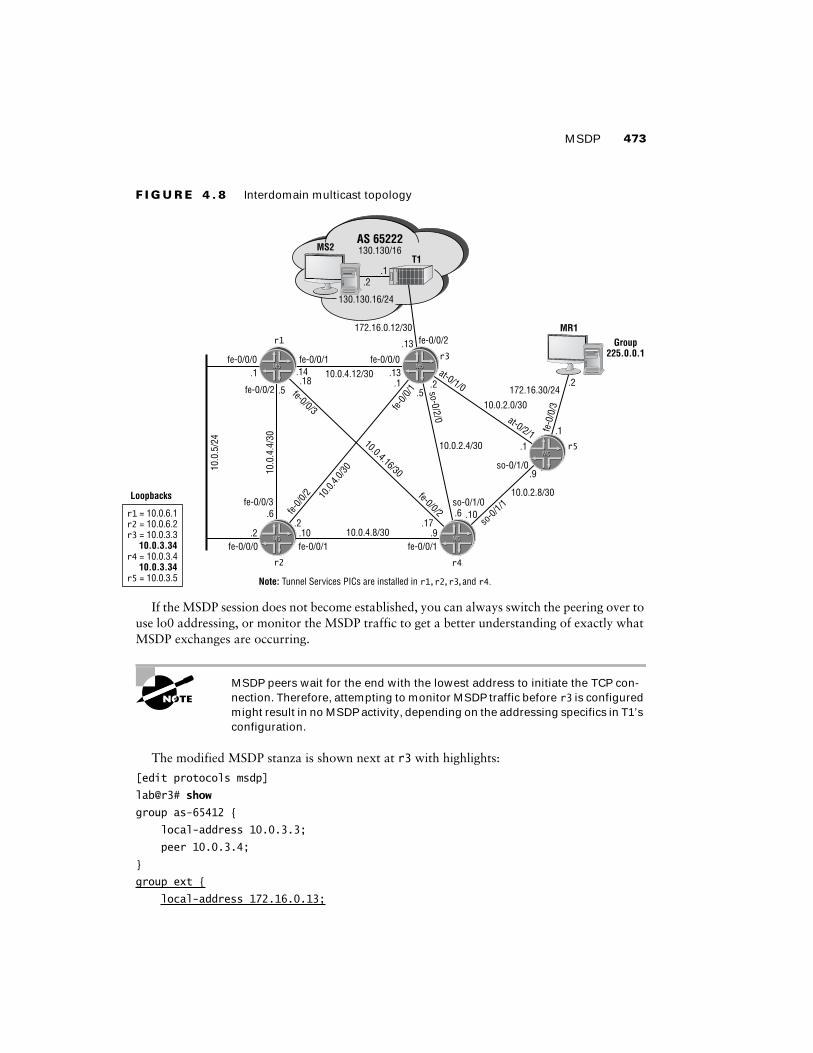
MSDP 473
F I G U R E 4 . 8 Interdomain multicast topology
If the MSDP session does not become established, you can always switch the peering over to use lo0 addressing, or monitor the MSDP traffic to get a better understanding of exactly what MSDP exchanges are occurring.
MSDP peers wait for the end with the lowest address to initiate the TCP con-nection. Therefore, attempting to monitor MSDP traffic before r3 is configured might result in no MSDP activity, depending on the addressing specifics in T1’s configuration.
The modified MSDP stanza is shown next at r3 with highlights:
[edit protocols msdp]
lab@r3# show
group as-65412 {
local-address 10.0.3.3;
peer 10.0.3.4;
}
group ext {
local-address 172.16.0.13;
Note: Tunnel Services PICs are installed in r1,r2,r3,and r4.
fe-0/0/0M5M5
M5M5
fe-0/0/1fe-0/0/0
r1
r2
fe-0/0/3
fe-0/0/0 fe-0/0/1
Group225.0.0.1
fe-0/0/1
fe-0/0/2
10.0
.5/2
4
10.0
.4.4
/30
fe-0/0/3
10.0.4.12/30
10.0.2.4/30
10.0.2.0/30
10.0.2.8/30
so-0/
1/1so-0/1/0
so-0/1/0
at-0/1/0
at-0/2/1
.1 .14 .13
.13
.9
.1
.1.5
.18
.2 .10 .910.0.4.8/30
10.0.4.16/30
fe-0/0
/1
fe-0/0
/2 10.0.
4.0/30
fe-0/0/2.2 .17
.6 .10
.2.5
r4
.6
so-0/2/0
M5M5
.1
.2
fe-0
/0/3
172.16.30/24
r5
AS 65222130.130/16
T1
M5M5r3
172.16.0.12/30
130.130.16/24
.2.1
fe-0/0/2
M5M5
Loopbacks
r4 = 10.0.3.4
r1 = 10.0.6.1r2 = 10.0.6.2r3 = 10.0.3.3
10.0.3.34
r5 = 10.0.3.510.0.3.34
MS2
MR1

474 Chapter 4 � Multicast
peer 172.16.0.14;
}
There is no need to MSDP-peer r4 with the T1 router because it will receive the source active messages sent by T1 through its MSDP peering session to r3. You must ensure that PIM is enabled on r3’s external interface to T1 (its fe-0/0/2 interface) in order for RPF checks to suc-ceed for 130.130/16 sources, however. With the ext MSDP peering group defined, you now address the need to filter source active messages received from T1 for groups in the 225.8/16 range. To this end, you configure the msdp policy as shown here:
[edit policy-options policy-statement msdp]
lab@r3# show
term 1 {
from {
route-filter 225.8.0.0/16 orlonger;
}
then reject;
}
You apply this policy as import to the ext MSDP peer group. Note that a global application of the msdp policy could result in point loss, because your instructions do not indicate that you should also filter these groups from any advertisements you receive from r4.
[edit protocols msdp]
lab@r3# set group ext import msdp
The modified MSDP stanza is displayed next at r3:
[edit protocols msdp]
lab@r3# show
group as-65412 {
local-address 10.0.3.3;
peer 10.0.3.4;
}
group ext {
import msdp;
local-address 172.16.0.13;
peer 172.16.0.14;
}
The final requirement in the interdomain multicast scenario requires that you filter Auto-RP messages from r3 to T1 to prevent T1 from learning your Any-Cast RP. You need to configure multicast scoping to block the output of Auto-RP announce and mapping messages on r3’s fe-0/0/2 interface to achieve this goal:
[edit routing-options multicast]
lab@r3# set scope announce interface fe-0/0/2 prefix 224.0.1.39
[edit routing-options multicast]
lab@r3# set scope discover interface fe-0/0/2 prefix 224.0.1.40

MSDP 475
Output filters are not possible for multicast traffic with M-series and T-series hardware (PR 24404). Multicast-based firewall matches are possible with ingress filters, however. Candidates have been observed trying to simulate the effects of multicast scoping with firewall filters applied in the output direction; these same candidates are normally observed deploying scoping when they come back for another go at the examination.
Note that two separate multicast scopes are needed to meet the criteria of blocking only Auto-RP related traffic on r3’s fe-0/0/2 interface. The modified routing-options stanza is displayed next with the additions highlighted:
[edit]
lab@r3# show routing-options
static {
route 10.0.200.0/24 {
next-hop 10.0.1.102;
no-readvertise;
}
}
aggregate {
route 10.0.0.0/16;
}
autonomous-system 65412;
multicast {
scope announce {
prefix 224.0.1.39/32;
interface fe-0/0/2.0;
}
scope discover {
prefix 224.0.1.40/32;
interface fe-0/0/2.0;
}
}
When satisfied with your MSDP and scoping changes, you should proceed to the next ses-sion. Note that you should not yet commit your changes for reasons that will soon be evident!
Verifying Interdomain Multicast
To help confirm (and demonstrate) the operation of MSDP, the tracing changes shown next are added to r3’s configuration:
[edit]
lab@r3# show protocols msdp traceoptions
file msdp;
flag source-active detail;

476 Chapter 4 � Multicast
flag normal detail;
flag packets detail;
flag policy detail;
You quickly begin monitoring the msdp log file after committing the changes:
[edit]
lab@r3# commit
commit complete
[edit]
lab@r3# run monitor start msdp
[edit]
lab@r3#
*** msdp ***
Apr 5 23:13:41 MSDP SENT Keepalive peer 10.0.3.4
Apr 5 23:13:49 RPD_MSDP_PEER_UP: MSDP peer 172.16.0.14 peer-group ext into Established state
Apr 5 23:13:49 MSDP RECV SA from 172.16.0.14 RP 130.130.0.1 count 2 len 32
Apr 5 23:13:49 MSDP Accept group 225.8.8.8 source 130.130.16.2 originator 130.130.0.1 from peer 172.16.0.14
Apr 5 23:13:49 MSDP Accept group 225.0.0.1 source 130.130.16.2 originator 130.130.0.1 from peer 172.16.0.14
Apr 5 23:13:49 MSDP HASH peer 10.0.3.4 adding 225.0.0.1.130.130.16.2 rp 130.130.0.1 to bucket 8 count 1
Apr 5 23:13:49 MSDP HASH removing 225.0.0.1.130.130.16.2 from bucket 8 count 1
Apr 5 23:13:49 MSDP SENT SA to 10.0.3.4 RP 130.130.0.1 len 20
. . .
The highlights call out the successful establishment of the MSDP session between T1 and r3, and also show that source active messages were received from T1 (130.130.0.1) for the 225.0.0.1 and 225.8.8.8 groups. Note that the trace output indicates that only one of the SA messages was forwarded on to MSDP peer 10.0.3.4; a behavior that is in keeping with your msdp policy, which serves to block SAs for groups in the 225.8/16 range. The MSDP tracing configuration is removed from r3, because it is no longer needed; leaving it in place should cause no harm, however:
[edit]
lab@r3# delete protocols msdp traceoptions
You now analyze the SA messages received by r3:
[edit]
lab@r3# run show msdp source-active
Group address Source address Peer address Originator Flags
225.0.0.1 130.130.16.2 172.16.0.14 130.130.0.1 Accept
225.8.8.8 130.130.16.2 172.16.0.14 130.130.0.1 Accept,Filtered

MSDP 477
The highlights confirm the receipt of two SA messages, and also confirm that the msdp policy is correctly filtering SAs in the 225.8/16 range. You next verify the proper conveyance of the SA for source 225.0.0.1 to r4. Recall that r3 and r4 are also MSDP peers in support of Any-Cast RP:
[edit]
lab@r4# run show msdp source-active
Group address Source address Peer address Originator Flags
225.0.0.1 130.130.16.2 10.0.3.3 130.130.0.1 Accept
With MSDP peering and policy confirmed, you move on to verify the correct flow of multicast traffic from MS2 to MR1. You start by analyzing the join state at r5:
[edit]
lab@r5# run show pim join 225.0.0.1 detail
Instance: PIM.master Family: INET
Group: 225.0.0.1
Source: *
RP: 10.0.3.34
Flags: sparse,rptree,wildcard
Upstream interface: at-0/2/1.0
Downstream interfaces:
fe-0/0/3.0
Group: 225.0.0.1
Source: 130.130.16.2
Flags: sparse,spt-pending
Upstream interface: at-0/2/1.0
Downstream interfaces:
fe-0/0/3.0
The S,G join state confirms that r5 has received traffic from MS2 via the shared RP tree, and that it has successfully established a SPT as a result. Another positive indication that traffic is being delivered to MR1 is obtained by the determination that both r3 and r5 are displaying the same traffic rate for the 130.130.16.2, 225.0.0.1 route:
[edit]
lab@r3# run show multicast route source-prefix 130.130.16.2 extensive
Family: INET
Group Source prefix Act Pru NHid Packets IfMismatch Timeout
225.0.0.1 130.130.16.2 /32 A F 79 4605 0 360
Upstream interface: fe-0/0/2.0
Session name: MALLOC
Forwarding rate: 3 kBps (5 pps)
[edit]

478 Chapter 4 � Multicast
lab@r5# run show multicast route source-prefix 130.130.16.2 extensive
Family: INET
Group Source prefix Act Pru NHid Packets IfMismatch Timeout
225.0.0.1 130.130.16.2 /32 A F 105 4876 0 360
Upstream interface: at-0/2/1.0
Session name: MALLOC
Forwarding rate: 3 kBps (5 pps)
r3 shows the correct upstream interface, and a packet rate of five packets per second, which matches the data rate shown at r5 nicely.
It may be difficult to confirm the operation of your multicast scoping, especially if you do not have access to the T1 device. In this example, you are provided with login information, which allows you to confirm that T1 has not learned of your Any-Cast RP:
[edit]
lab@r3# run telnet 130.130.0.1
Trying 130.130.0.1...
Connected to 130.130.0.1.
Escape character is '^]'.
T1-P1 (ttyp0)
login: lab
Password:
Last login: Sat Apr 5 14:10:42 on ttyd0
--- JUNOS 5.2R1.4 built 2002-01-30 17:03:27 UTC
lab@T1-P1> show pim rps
RP address Type Holdtime Timeout Active groups Group prefixes
130.130.0.1 static 0 None 1 224.0.0.0/4
Good, T1 has not learned your 10.0.3.34 Any-Cast RP. A quick glance at the PIM stanza confirms that T1 is configured to run Auto-RP and is listening to mapping messages, which means that it is configured to learn your RP in the event that scoping is not correctly configured:
[edit]
lab@T1-P1# show protocols pim
traceoptions {
file pim;
flag rp detail;
}
dense-groups {
224.0.1.39/32;

MSDP 479
224.0.1.40/32;
}
rp {
local {
address 130.130.0.1;
}
auto-rp discovery;
}
interface all {
mode sparse-dense;
}
The lack of Auto-RP entries at T1 confirms that the multicast scoping at r3 is having the desired effect. You can also use the show multicast scope command to confirm scoping settings:
[edit]
lab@r3# run show multicast scope
Resolve
Scope name Group Prefix Interface Rejects
announce 224.0.1.39/32 fe-0/0/2.0 2
discover 224.0.1.40/32 fe-0/0/2.0 0
local 239.255.0.0/16 fe-0/0/2.0 0
The output confirms that the addition of a custom scope range, in this case to control Auto-RP messages, automatically adds scoping for administratively scoped addresses in the range of 239.255.0.0 through 239.255.255.255 (239.255/16). The confirmation techniques demonstrated in this section indicate that your network meets all specified criteria for the interdomain multicast scenario.
MSDP Summary
MSDP is used to support interdomain multicast and Any-Cast RPs. Normally routers configured to run MSDP are also configured to function as a PIM RP. MSDP operates by sending source active messages to remote peers (using RPF forwarding to prevent loops), which causes the remote RP/MSDP peer to join a SPT for the active source when there are local listeners. Once the remote receiver begins receiving traffic from the active source via the shared tree, it too signals a SPT to the source.
Multicast scoping is used to block certain class D addresses from being sent out the specified interface. Scoping is configured under the routing-options stanza; you need to define multiple scopes when your goal is to block multiple /32 class D addresses. Note that firewall filters do not operate on class D addresses.
You can filter MSDP SAs and PIM joins using routing policy. This section provided an example of how import policy can be used to filter source active messages received from an MSDP peer. A similar approach is used when the goal is to filter joins to a RP-based shared tree or when filtering MSDP SA advertisements.
480 Chapter 4 � Multicast
SummaryThis chapter provided various examples of JNCIE-level multicast configuration scenarios ranging from IGMP to interdomain multicast using MSDP.
Multicast configuration is not really that difficult to configure. What most candidates do find difficult is making sense of the dynamic state and ever-changing landscape that is a multicast network. The fact that multicast technologies are not deployed in a widespread manner also adds to the mystique and the general lack of understanding when it comes to how multicast pro-tocols operate. The need for TS PICs in certain multicast environments can also hamper your ability to practice multicast configuration and troubleshooting in certain test beds and can lead to configuration mistakes in the JNCIE examination if the candidate does not design around the presence (or absence) of TS PICs.
A prepared JNCIE candidate will be ready to deploy multicast technology in scenarios similar to those demonstrated in this chapter.
Case Study: MulticastThe chapter case study is designed to simulate a JNCIE-level multicast configuration scenario. To keep things interesting, you will be adding your multicast configuration to the OSPF baseline configuration that was discovered and documented in the Chapter 1 case study. The OSPF baseline topology is shown in Figure 4.9 so you can reacquaint yourself with it.
Before starting the multicast case study, quickly verify the correct operation of the baseline network’s OSPF IGP, IS-IS route redistribution, and IBGP/EBGP peerings. Refer to previous case studies for suggestions on how to quickly verify the baseline network’s operation if needed. It is expected that a prepared JNCIE candidate will be able to complete this case study in approximately one hour with the resulting network meeting the majority of the specified behav-iors and operational characteristics.
Configuration listings that identify the changes made to the baseline configurations of all five routers in the multicast test bed are provided at the end of the case study for comparison with your own configurations. To accommodate differing configuration approaches, various oper-ational mode commands are included in the case study analysis to permit the comparison of your network to that of a known good example.
To complete the case study, you must configure your network to meet these criteria:� Add your multicast configuration to the OSPF baseline network.� Ensure that there is no single point of RP failure in your network.� Deploy PIM version 1 with at least two candidate RPs for groups in the range of 224.0.0.0
through 224.255.255.255.� Prevent external sites from discovering your RPs.� Ensure that traffic sent to group 224.1.1.1 is never sent to C1. This traffic must be delivered
to MR1.

Case Study: Multicast 481
� Configure r4 to deliver traffic sent to 224.2.2.2 to C1 without having it join a shared tree. Note that C1 is not configured to run MSDP.
� Filter all joins and source active messages for the 224.8.8.8 group.
F I G U R E 4 . 9 OSPF discovery findings
You can assume that the T1 and C1 routers are correctly configured, and that you are not permitted to modify their configurations or log into them remotely.
Multicast Case Study Analysis
To save space, initial verification of the baseline network is not performed here. Refer to previous chapters for suggested baseline network verification techniques and expected displays; the OSPF baseline network is assumed to be operational. Each configuration requirement for the
Area 1: Stub,default route
Area 0
IS-IS Level 1Area 0002
r2 r4
r7
r6
DataCenter
r5
r3r1
Area 2:NSSA, no
default route,corrected
M5M5
M5M5
M5M5
M5M5
M5M5
(192
.168
.0-3
)
Loopback addresses have not been assigned to specific areas (lo0 address advertised in Router LSA in all areas).
Passive OSPF interfaces on P1 and data center segments.
No authentication or route summarization in effect; summaries (LSA type 3) allowed in all areas.
Data center router running IS-IS, Level 1. r6 and r7 compatibly configured and adjacent.
Redistribution of 192.168.0/24 through 192.168.3/24 into OSPF from IS-IS by both r6 and r7.
Adjustment to IS-IS level 1 external preference to ensure r6 and r7 always prefer IS-IS level 1 externals overOSPF externals.
All adjacencies up and full reachability confirmed.
Sub-optimal routing detected at the data center router for some locations. This is the result of random nexthopchoice for its default route. Considered to be working as designed; no action taken.
Redistribution of OSPF default route to data center from both r6 and r7 was broken. Fixed with default-metriccommand on r3, r4, and r5.
Notes:
M5M5
M5M5
OSPFPassive
OSPFPassive
OSPFPassive
OSPFPassive
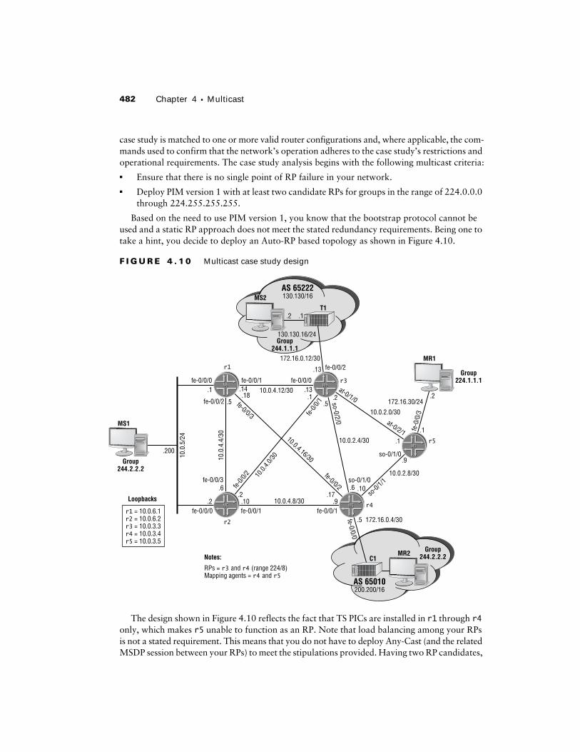
482 Chapter 4 � Multicast
case study is matched to one or more valid router configurations and, where applicable, the com-mands used to confirm that the network’s operation adheres to the case study’s restrictions and operational requirements. The case study analysis begins with the following multicast criteria:� Ensure that there is no single point of RP failure in your network.� Deploy PIM version 1 with at least two candidate RPs for groups in the range of 224.0.0.0
through 224.255.255.255.
Based on the need to use PIM version 1, you know that the bootstrap protocol cannot be used and a static RP approach does not meet the stated redundancy requirements. Being one to take a hint, you decide to deploy an Auto-RP based topology as shown in Figure 4.10.
F I G U R E 4 . 1 0 Multicast case study design
The design shown in Figure 4.10 reflects the fact that TS PICs are installed in r1 through r4 only, which makes r5 unable to function as an RP. Note that load balancing among your RPs is not a stated requirement. This means that you do not have to deploy Any-Cast (and the related MSDP session between your RPs) to meet the stipulations provided. Having two RP candidates,
fe-0/0/0M5M5
M5M5
fe-0/0/1fe-0/0/0
r1
r2
fe-0/0/3
fe-0/0/0 fe-0/0/1
Group224.1.1.1
fe-0/0/1
fe-0/0/0
fe-0/0/2
10.0
.5/2
4
10.0
.4.4
/30
fe-0/0/3
10.0.4.12/30
10.0.2.4/30
10.0.2.0/30
10.0.2.8/30
so-0/
1/1so-0/1/0
so-0/1/0
at-0/1/0
at-0/2/1
.200
.1 .14 .13
.13
.9
.1
.1.5
.18
.2 .10 .910.0.4.8/30
10.0.4.16/30
fe-0/0
/1
fe-0/0
/2 10.0.
4.0/30
fe-0/0/2.2 .17
.5 172.16.0.4/30
.6 .10
.2.5
r4Loopbacks
r1 = 10.0.6.1r2 = 10.0.6.2r3 = 10.0.3.3r4 = 10.0.3.4r5 = 10.0.3.5
.6
so-0/2/0
M5M5
.1
.2
fe-0
/0/3
172.16.30/24
r5
AS 65222130.130/16
T1
M5M5r3
172.16.0.12/30
130.130.16/24.2
.1.2
fe-0/0/2
Group244.1.1.1
Group244.2.2.2
AS 65010200.200/16
C1RPs = r3 and r4 (range 224/8)Mapping agents = r4 and r5
Notes:Group
244.2.2.2
M5M5
MS1
MR1
MS2
MR2

Case Study: Multicast 483
and at least two mapping agents, provides the RP redundancy required in this example. The changes made to r3 are shown next:
[edit protocols pim]
lab@r3# show
dense-groups {
224.0.1.39/32;
224.0.1.40/32;
}
rp {
local {
address 10.0.3.3;
group-ranges {
224.0.0.0/8;
}
}
auto-rp announce;
}
interface all {
mode sparse-dense;
version 1;
}
interface fxp0.0 {
disable;
The configuration of r4 is similar to that shown for r3, with the exception of its local RP address and the use of the mapping keyword. The modifications made to r5 in support of the first two case study criteria are displayed next:
[edit protocols pim]
lab@r5# show
dense-groups {
224.0.1.39/32;
224.0.1.40/32;
}
rp {
auto-rp mapping;
}
interface all {
mode sparse-dense;
version 1;
}
interface fxp0.0 {
disable;
}

484 Chapter 4 � Multicast
Proper PIM version and Auto-RP election are now verified at r5:
[edit protocols pim]
lab@r5# run show pim interfaces
Instance: PIM.master
Name Stat Mode IP V State Count DR address
at-0/2/1.0 Up SparseDense 4 1 P2P 1
fe-0/0/0.0 Up SparseDense 4 1 DR 0 10.0.8.6
fe-0/0/1.0 Up SparseDense 4 1 DR 0 10.0.8.9
lo0.0 Up SparseDense 4 1 DR 0 10.0.3.5
so-0/1/0.0 Up SparseDense 4 1 P2P 1
[edit protocols pim]
lab@r5# run show pim neighbors
Instance: PIM.master
Interface IP V Mode Option Uptime Neighbor addr
at-0/2/1.0 4 1 SparseDense 00:06:22 10.0.2.2
so-0/1/0.0 4 1 SparseDense 00:05:27 10.0.2.10
These displays confirm the correct PIM protocol version, the required sparse-dense mode of operation (as needed for Auto-RP), and that PIM neighbors have been detected. You move on to verify RP election results, again at r5:
[edit protocols pim]
lab@r5# run show pim rps
Instance: PIM.master
Family: INET
RP address Type Holdtime Timeout Active groups Group prefixes
10.0.3.4 auto-rp 150 104 0 224.0.0.0/8
Family: INET6
RP address Type Holdtime Timeout Active groups Group prefixes
Proper RP mapping is confirmed when r3 displays the same Auto-RP elected RP:
[edit protocols pim]
lab@r3# run show pim rps
Instance: PIM.master
Family: INET
RP address Type Holdtime Timeout Active groups Group prefixes
10.0.3.4 auto-rp 150 147 0 224.0.0.0/8
10.0.3.3 static 0 None 0 224.0.0.0/8
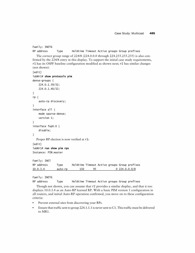
Case Study: Multicast 485
Family: INET6
RP address Type Holdtime Timeout Active groups Group prefixes
The correct group range of 224/8 (224.0.0.0 through 224.255.255.255) is also con-firmed by the 224/8 entry in this display. To support the initial case study requirements, r1 has its OSPF baseline configuration modified as shown next; r2 has similar changes (not shown):
[edit]
lab@r1# show protocols pim
dense-groups {
224.0.1.39/32;
224.0.1.40/32;
}
rp {
auto-rp discovery;
}
interface all {
mode sparse-dense;
version 1;
}
interface fxp0.0 {
disable;
}
Proper RP election is now verified at r1:
[edit]
lab@r1# run show pim rps
Instance: PIM.master
Family: INET
RP address Type Holdtime Timeout Active groups Group prefixes
10.0.3.4 auto-rp 150 95 0 224.0.0.0/8
Family: INET6
RP address Type Holdtime Timeout Active groups Group prefixes
Though not shown, you can assume that r2 provides a similar display, and that it too displays 10.0.3.4 as an Auto-RP learned RP. With a basic PIM version 1 configuration inall routers, and initial Auto-RP operation confirmed, you move on to these configuration criteria:� Prevent external sites from discovering your RPs.� Ensure that traffic sent to group 224.1.1.1 is never sent to C1. This traffic must be delivered
to MR1.

486 Chapter 4 � Multicast
Because you need to configure multicast scoping to prevent other networks from learning about your RPs, you decide to also use scoping at r4 in support of the requirement that traffic for group 224.1.1.1 is not to be sent to customer C1. Note that trying to meet the stated behavior using a PIM join policy such as this one could result in point loss:
[edit policy-options]
lab@r4# show policy-statement pim-join
term 1 {
from {
route-filter 224.1.1.1/32 exact reject;
}
}
This is because the pim-join policy will cause problems when it prevents internal and external ∗,G joins for the 224.1.1.1 group. In this example, you need the added granularity of scoping, which can be applied to individual interfaces, instead of the global effects that a PIM join policy brings to the table. The changes made to r4’s configuration are shown here with highlights added:
[edit]
lab@r4# show routing-options
static {
route 10.0.200.0/24 {
next-hop 10.0.1.102;
no-readvertise;
}
}
aggregate {
route 10.0.0.0/16;
}
autonomous-system 65412;
multicast {
scope auto-rp-announce {
prefix 224.0.1.39/32;
interface fe-0/0/0.0;
}
scope auto-rp-discover {
prefix 224.0.1.40/32;
interface fe-0/0/0.0;
}
scope block-224.1.1.1 {
prefix 224.1.1.1/32;
interface fe-0/0/0.0;
}
}
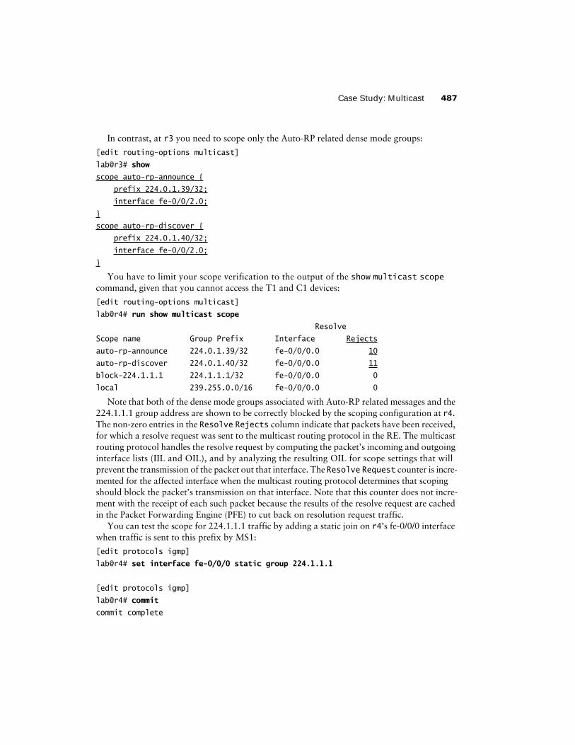
Case Study: Multicast 487
In contrast, at r3 you need to scope only the Auto-RP related dense mode groups:
[edit routing-options multicast]
lab@r3# show
scope auto-rp-announce {
prefix 224.0.1.39/32;
interface fe-0/0/2.0;
}
scope auto-rp-discover {
prefix 224.0.1.40/32;
interface fe-0/0/2.0;
}
You have to limit your scope verification to the output of the show multicast scope command, given that you cannot access the T1 and C1 devices:
[edit routing-options multicast]
lab@r4# run show multicast scope
Resolve
Scope name Group Prefix Interface Rejects
auto-rp-announce 224.0.1.39/32 fe-0/0/0.0 10
auto-rp-discover 224.0.1.40/32 fe-0/0/0.0 11
block-224.1.1.1 224.1.1.1/32 fe-0/0/0.0 0
local 239.255.0.0/16 fe-0/0/0.0 0
Note that both of the dense mode groups associated with Auto-RP related messages and the 224.1.1.1 group address are shown to be correctly blocked by the scoping configuration at r4. The non-zero entries in the Resolve Rejects column indicate that packets have been received, for which a resolve request was sent to the multicast routing protocol in the RE. The multicast routing protocol handles the resolve request by computing the packet’s incoming and outgoing interface lists (IIL and OIL), and by analyzing the resulting OIL for scope settings that will prevent the transmission of the packet out that interface. The Resolve Request counter is incre-mented for the affected interface when the multicast routing protocol determines that scoping should block the packet’s transmission on that interface. Note that this counter does not incre-ment with the receipt of each such packet because the results of the resolve request are cached in the Packet Forwarding Engine (PFE) to cut back on resolution request traffic.
You can test the scope for 224.1.1.1 traffic by adding a static join on r4’s fe-0/0/0 interface when traffic is sent to this prefix by MS1:
[edit protocols igmp]
lab@r4# set interface fe-0/0/0 static group 224.1.1.1
[edit protocols igmp]
lab@r4# commit
commit complete

488 Chapter 4 � Multicast
[edit protocols igmp]
lab@r4# run show multicast scope
Resolve
Scope name Group Prefix Interface Rejects
auto-rp-announce 224.0.1.39/32 fe-0/0/0.0 58
auto-rp-discover 224.0.1.40/32 fe-0/0/0.0 58
block-224.1.1.1 224.1.1.1/32 fe-0/0/0.0 9
local 239.255.0.0/16 fe-0/0/0.0 0
The non-zero count value confirms that packets addressed to group 224.1.1.1 are correctly blocked at r4’s fe-0/0/0 interface. Also note how the fe-0/0/0 interface is pruned as a result of scoping; this behavior means that the block-224.1.1.1 counter increments for only a brief period after each clearing of PIM joins at r4:
lab@r4# run show pim join detail 224.1.1.1
Instance: PIM.master Family: INET
Group: 224.1.1.1
Source: *
RP: 10.0.3.4
Flags: sparse,rptree,wildcard
Upstream interface: local
Downstream interfaces:
fe-0/0/0.0 (administratively scoped)
Group: 224.1.1.1
Source: 10.0.5.200
Flags: sparse,spt
Upstream interface: fe-0/0/2.0
Downstream interfaces:
Note the absence of downstream interfaces in the S,G join for the 224.1.1.1 group due to your administrative scoping. Be sure to remove the static join for 224.1.1.1 from r4 when satisfied with the operation of your scope settings. With scoping confirmed, you move onto the following criteria; note that some aspects of the first requirements have already been accommodated:� Ensure that traffic sent to group 224.1.1.1 is never sent to C1. This traffic must be delivered
to MR1.� Configure r4 to deliver traffic sent from 10.0.5.200 to group 224.2.2.2 to C1 without
having it join a shared tree. Note that C1 is not configured to run MSDP.
The first criterion requires a static ∗,G join on r5’s fe-0/0/3 interface, and that you correctly establish a MSDP peering session to T1 from all candidate RPs. The wording of the second requirement might confuse candidates who are not familiar with the concept of source specific multicast (SSM). You do not need to configure IGMP version 3 on r4’s fe-0/0/0 interface to sup-port a static S,G join, but version 3 is needed to support SSM joins from attached hosts through IGMP. Note that configuring version 3 on r4’s fe-0/0/0 interface causes no harm in this scenario.

Case Study: Multicast 489
The changes made to r5 are shown next:
[edit protocols igmp]
lab@r5# show
interface fe-0/0/3.0 {
static {
group 224.1.1.1;
}
}
[edit]
lab@r5# show interfaces fe-0/0/3
unit 0 {
family inet {
address 172.16.30.2/24;
}
}
Make sure to configure IP parameters on r5’s fe-0/0/3 interface, which was not used in the OSPF baseline topology. The changes made to r4 in support of static IGMP joins is displayed next; note the presence of a source address in the static join declaration for group 224.2.2.2:
[edit protocols igmp]
lab@r4# show
interface fe-0/0/0.0 {
static {
group 224.2.2.2 {
source 10.0.5.200;
}
}
}
To confirm your static join configuration, view the PIM join at r4 and r5. You expect to see a ∗,G, and ultimately a S,G join at r5 for the 224.2.2.2 group, but you should see only a S,G join at r4 for the 224.2.2.2 group:
[edit protocols igmp]
lab@r4# run show pim join 224.2.2.2 detail
Instance: PIM.master Family: INET
Group: 224.2.2.2
Source: 10.0.5.200
Flags: sparse
Upstream interface: fe-0/0/2.0
Downstream interfaces:
fe-0/0/0.0

490 Chapter 4 � Multicast
The S,G join is present at r4, as is the ∗,G entry at r5:
[edit]
lab@r5# run show pim join 224.1.1.1
Instance: PIM.master Family: INET
Group: 224.1.1.1
Source: *
RP: 10.0.3.4
Flags: sparse,rptree,wildcard
Upstream interface: so-0/1/0.0
With the static joins configured and confirmed, you need to configure MSDP peering at r3 and r4 so that source active messages are received from T1 when MS1 is sending to group 224.1.1.1. Note that you need to MSDP peer from r3 and r4 to T1, because either r3 or r4 can function as the RP for your multicast domain. You do not need to peer the two RPs with MSDP. Because you have not configured Any-Cast in this example, only one of the two RP candidates will be active for all groups in the 224/8 range at any given time. The changes made to r3 are displayed:
[edit]
lab@r3# show protocols msdp
group t1 {
local-address 172.16.0.13;
peer 172.16.0.14;
}
The MSDP configuration at r4 is similar to that shown for r3, excepting the use of loopback-based peering addresses. The use of lo0 addressing is necessary at r4 in this case, because it does not have a route to the 172.16.0.12/30 peering subnet between r3 and the T1 router:
[edit]
lab@r4# show protocols msdp
group t1 {
local-address 10.0.3.4;
peer 130.130.0.1;
}
Proper MSDP session establishment is now verified at both r3 and r4, as is the receipt of source active messages for 130.130.16.2:
[edit]
lab@r3# run show msdp
Peer address Local address State Last up/down Peer-Group
172.16.0.14 172.16.0.13 Established 00:00:25 t1
[edit]
lab@r3# run show msdp source-active

Case Study: Multicast 491
Group address Source address Peer address Originator Flags
224.1.1.1 130.130.16.2 172.16.0.14 130.130.0.1 Accept
The same commands are now issued at r4:
[edit]
lab@r4# run show msdp
Peer address Local address State Last up/down Peer-Group
130.130.0.1 10.0.3.4 Established 00:00:05 t1
[edit]
lab@r4# run show msdp source-active
Group address Source address Peer address Originator Flags
224.1.1.1 130.130.16.2 130.130.0.1 130.130.0.1 Accept
224.2.2.2 10.0.5.200 local 10.0.3.4 Accept
With MSDP operational, and assuming that both multicast sources are actively sending, you expect to see S,G join state at r4 and r5, as well as indications that the multicast traffic is being forwarded out the correct interfaces.
[edit protocols igmp]
lab@r4# run show pim join 224.2.2.2 detail
Instance: PIM.master Family: INET
Group: 224.2.2.2
Source: 10.0.5.200
Flags: sparse
Upstream interface: fe-0/0/2.0
Downstream interfaces:
fe-0/0/0.0
[edit protocols igmp]
lab@r4# run show multicast route source-prefix 10.0.5.200 extensive
Family: INET
Group Source prefix Act Pru NHid Packets IfMismatch Timeout
224.2.2.2 10.0.5.200 /32 A F 79 11323 1 360
Upstream interface: fe-0/0/2.0
Session name: Multimedia Conference Calls
Forwarding rate: 5 kBps (16 pps)
[edit protocols igmp]
lab@r4# run show multicast next-hops 79
Family: INET
ID Refcount KRefcount Downstream interface
79 2 1 fe-0/0/0.0

492 Chapter 4 � Multicast
Family: INET6
[edit protocols igmp]
r4 has the expected S,G state, and the interface linking it to C1 is correctly listed as a down-stream interface for the 224.2.2.2 group. Also of note is the 16-packet-per-second data rate and forwarding indication in the show multicast route display, because this provides good indi-cation that traffic is correctly flowing from MS1 to C1. With forwarding confirmed at r4, the same commands are issued at r5 with attention focused on the 224.1.1.1 join and forwarding state:
[edit]
lab@r5# run show pim join 224.1.1.1 detail
Instance: PIM.master Family: INET
Group: 224.1.1.1
Source: *
RP: 10.0.3.4
Flags: sparse,rptree,wildcard
Upstream interface: so-0/1/0.0
Downstream interfaces:
fe-0/0/3.0
Group: 224.1.1.1
Source: 130.130.16.2
Flags: sparse,spt
Upstream interface: at-0/2/1.0
Downstream interfaces:
fe-0/0/3.0
The join state shows both a shared tree and SPT join for the 224.1.1.1 group, as expected. Note that the S,G join list at-0/2/1 is the upstream interface, which is in keeping with its lying on the shortest path back to source MS2. At this time, r4 is the route of the shared tree, and this accounts for the ∗,G entry listing the so-0/1/0 interface as upstream.
[edit]
lab@r5# run show multicast route source-prefix 130.130.16.2 extensive
Family: INET
Group Source prefix Act Pru NHid Packets IfMismatch Timeout
224.1.1.1 130.130.16.2 /32 A F 71 3191 1 360
Upstream interface: at-0/2/1.0
Session name: ST Multicast Groups
Forwarding rate: 4 kBps (8 pps)

Case Study: Multicast 493
[edit]
lab@r5# run show multicast next-hops 71
Family: INET
ID Refcount KRefcount Downstream interface
71 2 1 fe-0/0/3.0
Family: INET6
The displays at r5 confirm that packets associated with the 224.1.1.1 group are being correctly forwarded to MR1 using r5’s fe-0/0/3 interface. With multicast forwarding confirmed, the last criterion to be addressed relates to your need to filter PIM join and MSDP SA messages:� Filter all joins and SAs for the 224.8.8.8 group.
This task is designed to verify that you can control the source active and PIM joins that your RPs will accept. The following policy and configuration changes correctly configure r3 to block source active messages and PIM joins to the 224.8.8.8 group, regardless of their source:
[edit]
lab@r3# show policy-options policy-statement block-224.8.8.8
term 1 {
from {
route-filter 224.8.8.8/32 exact reject;
}
}
[edit]
lab@r3# show protocols pim import
import block-224.8.8.8;
[edit]
lab@r3# show protocols msdp import
import block-224.8.8.8;
Note that the block-224.8.8.8 policy is applied globally to the MSDP instance in keeping with the requirement that all SA messages to 224.8.8.8 be blocked. It will be difficult to confirm the correct operation of MSDP unless you can access and configure the MS2 device so that it begins sending to the 224.8.8.8 group. To test local RP behavior, just add a static join to one of the routers:
[edit protocols igmp]
lab@r2# show
interface fe-0/0/0.0 {
static {
group 224.8.8.8;

494 Chapter 4 � Multicast
}
}
[edit protocols igmp]
lab@r2# run show pim join 224.8.8.8 detail
Instance: PIM.master Family: INET
Group: 224.8.8.8
Source: *
RP: 10.0.3.4
Flags: sparse,rptree,wildcard
Upstream interface: fe-0/0/1.0
Downstream interfaces:
fe-0/0/0.0
Note that r2 has generated a ∗,G join toward the RP using its fe-0/0/1 interface. Correct join filtering is confirmed by the absence of a ∗,G join for the 224.8.8.8 group at the current RP, which is r4 in this case:
[edit]
lab@r4# run show pim join 224.8.8.8
Instance: PIM.master Family: INET
[edit]
lab@r4#
The lack of a ∗,G join at the RP provides a good indication that your block-224.8.8.8 policy is correctly filtering joins. These results, combined with the previous confirmation steps, indicate that your network is operating within the confines of all case study criteria provided. Congratulations!
Multicast Case Study Configurations
The changes made to the OSPF baseline network topology to support the multicast case study are listed next for all routers in the multicast test bed with highlights added as needed to call out changes to existing configuration stanzas (see Listings 4.1 to 4.5).
Listing 4.1: Multicast Case Study Configuration for r1
[edit]
lab@r1# show protocols pim
dense-groups {
224.0.1.39/32;
224.0.1.40/32;
}
rp {
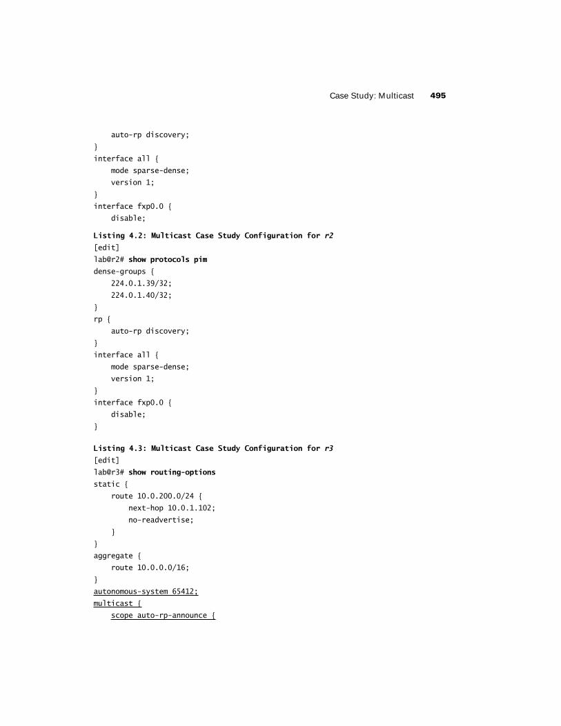
Case Study: Multicast 495
auto-rp discovery;
}
interface all {
mode sparse-dense;
version 1;
}
interface fxp0.0 {
disable;
Listing 4.2: Multicast Case Study Configuration for r2
[edit]
lab@r2# show protocols pim
dense-groups {
224.0.1.39/32;
224.0.1.40/32;
}
rp {
auto-rp discovery;
}
interface all {
mode sparse-dense;
version 1;
}
interface fxp0.0 {
disable;
}
Listing 4.3: Multicast Case Study Configuration for r3
[edit]
lab@r3# show routing-options
static {
route 10.0.200.0/24 {
next-hop 10.0.1.102;
no-readvertise;
}
}
aggregate {
route 10.0.0.0/16;
}
autonomous-system 65412;
multicast {
scope auto-rp-announce {

496 Chapter 4 � Multicast
prefix 224.0.1.39/32;
interface fe-0/0/2.0;
}
scope auto-rp-discover {
prefix 224.0.1.40/32;
interface fe-0/0/2.0;
}
}
[edit]
lab@r3# show protocols pim
dense-groups {
224.0.1.39/32;
224.0.1.40/32;
}
import block-224.8.8.8;
rp {
local {
address 10.0.3.3;
group-ranges {
224.0.0.0/8;
}
}
auto-rp announce;
}
interface all {
mode sparse-dense;
version 1;
}
interface fxp0.0 {
disable;
}
[edit]
lab@r3# show protocols msdp
group t1 {
import block-224.8.8.8;
local-address 172.16.0.13;
peer 172.16.0.14;
}
[edit]

Case Study: Multicast 497
lab@r3# show policy-options policy-statement block-224.8.8.8
term 1 {
from {
route-filter 224.8.8.8/32 exact reject;
}
}
Listing 4.4: Multicast Case Study Configuration for r4
[edit]
lab@r4# show routing-options
static {
route 10.0.200.0/24 {
next-hop 10.0.1.102;
no-readvertise;
}
}
aggregate {
route 10.0.0.0/16;
}
autonomous-system 65412;
multicast {
scope auto-rp-announce {
prefix 224.0.1.39/32;
interface fe-0/0/0.0;
}
scope auto-rp-discover {
prefix 224.0.1.40/32;
interface fe-0/0/0.0;
}
scope block-224.1.1.1 {
prefix 224.1.1.1/32;
interface fe-0/0/0.0;
}
}
[edit]
lab@r4# show protocols pim
dense-groups {
224.0.1.39/32;
224.0.1.40/32;
}
import block-224.8.8.8;
rp {

498 Chapter 4 � Multicast
local {
address 10.0.3.4;
group-ranges {
224.0.0.0/8;
}
}
auto-rp mapping;
}
interface all {
mode sparse-dense;
version 1;
}
interface fxp0.0 {
disable;
}
[edit]
lab@r4# show protocols msdp
group t1 {
import block-224.8.8.8;
local-address 10.0.3.4;
peer 130.130.0.1;
}
[edit]
lab@r4# show protocols igmp
interface fe-0/0/0.0 {
version 3;
static {
group 224.2.2.2 {
source 10.0.5.200;
}
}
}
[edit]
lab@r4# show policy-options policy-statement block-224.8.8.8
term 1 {
from {
route-filter 224.8.8.8/32 exact reject;
}
}

Case Study: Multicast 499
Listing 4.5: Multicast Case Study Configuration for r5
[edit]
lab@r5# show interfaces fe-0/0/3
unit 0 {
family inet {
address 172.16.30.2/24;
}
}
[edit]
lab@r5# show protocols pim
dense-groups {
224.0.1.39/32;
224.0.1.40/32;
}
rp {
auto-rp mapping;
}
interface all {
mode sparse-dense;
version 1;
}
interface fxp0.0 {
disable;
}
[edit]
lab@r5# show protocols igmp
interface fe-0/0/3.0 {
static {
group 224.1.1.1;
}
}
r6 was not part of the multicast test bed. No changes were made to its configuration as part of the chapter’s case study.
r7 was not part of the multicast test bed. No changes were made to its configuration as part of the chapter’s case study.

500 Chapter 4 � Multicast
Spot the Issues: Review Questions1. Is this a valid configuration for r4 according to the case study requirements?
[edit protocols] lab@r4# show pim
dense-groups {
224.0.1.39/32;
224.0.1.40/32;
}
rp {
local {
address 10.0.3.4;
group-ranges {
224.0.0.0/3;
}
}
auto-rp mapping;
}
interface all {
mode sparse-dense;
version 1;
}
interface fxp0.0 {
disable;
}
2. Interdomain multicast is not working in the case study topology. Can you locate the problem in r3’s configuration?
[edit protocols pim]
lab@r3# show
dense-groups {
224.0.1.39/32;
224.0.1.40/32;
}
import block-224.8.8.8;
rp {
local {
address 10.0.3.3;

Spot the Issues: Review Questions 501
group-ranges {
224.0.0.0/8;
}
}
auto-rp announce;
}
interface fxp0.0 {
disable;
}
interface fe-0/0/0.0 {
mode sparse-dense;
version 1;
}
interface fe-0/0/1.0 {
mode sparse-dense;
version 1;
}
interface so-0/2/0.100 {
mode sparse-dense;
version 1;
}
interface at-0/1/0.0 {
mode sparse-dense;
version 1;
}
interface lo0.0 {
mode sparse-dense;
version 1;
}
3. Why is the bootstrap protocol not working between r2 and r4?
[edit]
lab@r2# show protocols pim
interface all {
mode sparse;
version 1;
}
interface fxp0.0 {
disable;
}

502 Chapter 4 � Multicast
[edit]
lab@r4# show protocols pim
rp {
bootstrap-priority 10;
local {
address 10.0.3.4;
}
}
interface all {
mode sparse;
version 1;
}
interface fxp0.0 {
disable;
}
4. r3 is filtering all SA messages with the case study–based MSDP configuration shown here. Can you spot the issue?
[edit]
lab@r3# show protocols msdp
import block-224.8.8.8;
group t1 {
local-address 172.16.0.13;
peer 172.16.0.14;
}
[edit]
lab@r3# show policy-options policy-statement block-224.8.8.8
term 1 {
from {
route-filter 224.8.8.8/32 exact;
}
}
then reject;
5. DVMRP is not working correctly at r5 in the topology shown earlier in Figure 4.2. Can you spot the problem?
[edit]
lab@r5# show routing-options
static {
route 10.0.200.0/24 {

Spot the Issues: Review Questions 503
next-hop 10.0.1.102;
no-readvertise;
}
}
rib-groups {
dvmrp-rg {
export-rib inet.2;
import-rib inet.2;
}
}
autonomous-system 65412;
[edit]
lab@r5# show protocols dvmrp
rib-group dvmrp-rg;
interface all {
hold-time 40;
}
interface fxp0.0 {
disable;
}
6. With r4 shut down, r3 has been elected the RP in the topology shown earlier in Figure 4.6. How-ever, r1 never shows a S,G join for source 10.0.5.200 and group 224.1.1.1, and the multicast traffic is not being delivered to MR1. Can you spot the problem based on this display?
lab@r3> show interfaces terse
Interface Admin Link Proto Local Remote
fe-0/0/0 up up
fe-0/0/0.0 up up inet 10.0.4.13/30
fe-0/0/1 up up
fe-0/0/1.0 up up inet 10.0.4.1/30
fe-0/0/2 up up
fe-0/0/2.0 up up inet 172.16.0.13/30
fe-0/0/3 up down
fe-0/0/3.0 up down inet 10.0.2.14/30
at-0/1/0 up up
at-0/1/0.0 up up inet 10.0.2.2/30
at-0/1/1 up down
so-0/2/0 up up
so-0/2/0.100 up up inet 10.0.2.5/30
so-0/2/1 up down

504 Chapter 4 � Multicast
so-0/2/2 up down
so-0/2/3 up down
dsc up up
fxp0 up up
fxp0.0 up up inet 10.0.1.3/24
fxp1 up up
fxp1.0 up up tnp 4
gre up up
ipip up up
lo0 up up
lo0.0 up up inet 10.0.3.3 --> 0/0
lsi up up
mtun up up
pimd up up
pime up up
tap up up

Spot the Issues: Answers to Review Questions 505
Spot the Issues: Answers to Review Questions1. No. The problem with r4’s configuration relates to the incorrect specification of the class D
group range as 224/3 instead of 224/4. Although this configuration commits, other routers will not install r4 as an RP with this group range setting. Note that omitting the group-range statement results in a default of 224/4.
2. The problem relates to the lack of PIM support on r3’s fe-0/0/2 interface. Although r3 will receive MSDP SAs with this configuration, it will be unable to forward S,G joins to T1, and this prevents the flow of multicast from MS2.
3. The bootstrap protocol requires PIM version 2. Both r2 and r3 are set for version 1. Note that with this configuration, r4 elects itself the BSR and displays itself as a bootstrap-learned RP; the problem is that other routers in the test bed do not share r4’s view.
4. The issue with this configuration lies in the block-224.8.8.8 policy, and the fact that the reject action was not added as part of term 1. As written, the reject action is considered a final (unnamed) term that matches on all SA messages due to the lack of explicit match criteria in the final term. A corrected policy is shown here:
[edit] lab@r3# show policy-options policy-statement block-224.8.8.8
term 1 {
from {
route-filter 224.8.8.8/32 exact;
}
then reject;
}
5. The problem in this example is a lack of interface RIB group definition under the routing-options stanza, which prevents the installation of interface routes in the inet.2 table. The presence of interface routes is necessary in inet.2 to accommodate RPF checks, as shown next:
[edit] lab@r5# run show multicast rpf 10.0.2.0/30
Multicast RPF table: inet.2, 11 entries
[edit]
lab@r5#

506 Chapter 4 � Multicast
To correct the problem, create an interface RIB group as shown here:
[edit] lab@r5# show routing-options
interface-routes {
rib-group inet interface-rib;
}
static {
route 10.0.200.0/24 {
next-hop 10.0.1.102;
no-readvertise;
}
}
rib-groups {
interface-rib {
import-rib [ inet.0 inet.2 ];
}
dvmrp-rg {
export-rib inet.2;
import-rib inet.2;
}
}
autonomous-system 65412;
With interface routes in the inet.2 table, RPF checks will succeed.
[edit] lab@r5# run show multicast rpf 10.0.2.0/30
Multicast RPF table: inet.2, 21 entries
10.0.2.0/30
Protocol: Direct
Interface: at-0/2/1.0
10.0.2.1/32
Protocol: Local

Spot the Issues: Answers to Review Questions 507
6. In this case, the problem is a lack of Tunnel Services PIC hardware at r3. Although r3 displays a pimd and pime interface, the lack of TS PIC hardware means that r3 cannot back up these virtual interfaces. Without the TS PIC, r3 cannot perform register message de-encapsulation, so r5 never receives traffic on the shared tree, and therefore r5 never initiates a S,G join back to the source. After re-installing the TS PIC in r3, the presence of a PIM de-encapsulation interface is confirmed.
lab@r3> show interfaces terse Interface Admin Link Proto Local Remote
fe-0/0/0 up up
. . .
mt-0/3/0 up up
pd-0/3/0 up up
pd-0/3/0.32768 up up inet
pe-0/3/0 up up
. . .
tap up up