Embed Size (px)
Citation preview
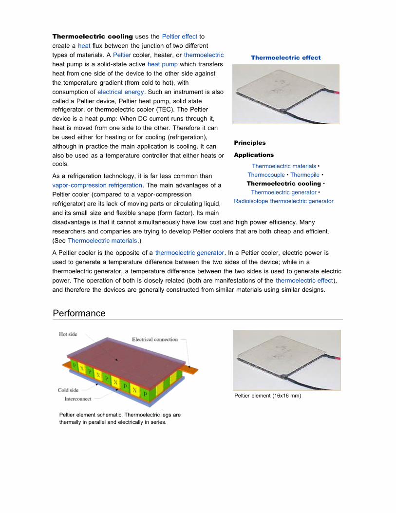
Thermoelectric effect
Principles
Applications
Thermoelectric materials ·Thermocouple · Thermopile ·Thermoelectric cooling ·
Thermoelectric generator ·Radioisotope thermoelectric generator
Thermoelectric cooling uses the Peltier effect tocreate a heat flux between the junction of two differenttypes of materials. A Peltier cooler, heater, or thermoelectricheat pump is a solid-state active heat pump which transfersheat from one side of the device to the other side againstthe temperature gradient (from cold to hot), withconsumption of electrical energy. Such an instrument is alsocalled a Peltier device, Peltier heat pump, solid staterefrigerator, or thermoelectric cooler (TEC). The Peltierdevice is a heat pump: When DC current runs through it,heat is moved from one side to the other. Therefore it canbe used either for heating or for cooling (refrigeration),although in practice the main application is cooling. It canalso be used as a temperature controller that either heats orcools.
As a refrigeration technology, it is far less common thanvapor-compression refrigeration. The main advantages of aPeltier cooler (compared to a vapor-compressionrefrigerator) are its lack of moving parts or circulating liquid,and its small size and flexible shape (form factor). Its maindisadvantage is that it cannot simultaneously have low cost and high power efficiency. Manyresearchers and companies are trying to develop Peltier coolers that are both cheap and efficient.(See Thermoelectric materials.)
A Peltier cooler is the opposite of a thermoelectric generator. In a Peltier cooler, electric power isused to generate a temperature difference between the two sides of the device; while in athermoelectric generator, a temperature difference between the two sides is used to generate electricpower. The operation of both is closely related (both are manifestations of the thermoelectric effect),and therefore the devices are generally constructed from similar materials using similar designs.
Performance
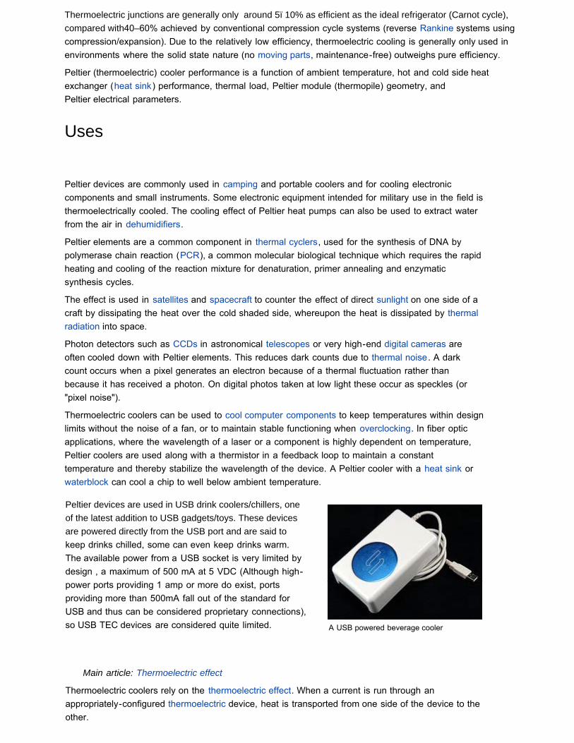
Peltier element (16x16 mm)
Peltier element schematic. Thermoelectric legs arethermally in parallel and electrically in series.
Thermoelectric junctions are generally only around 5ï10% as efficient as the ideal refrigerator (Carnot cycle), compared with40–60% achieved by conventional compression cycle systems (reverse Rankine systems usingcompression/expansion). Due to the relatively low efficiency, thermoelectric cooling is generally only used inenvironments where the solid state nature (no moving parts, maintenance-free) outweighs pure efficiency.
Peltier (thermoelectric) cooler performance is a function of ambient temperature, hot and cold side heatexchanger (heat sink) performance, thermal load, Peltier module (thermopile) geometry, andPeltier electrical parameters.
Uses
Peltier devices are commonly used in camping and portable coolers and for cooling electroniccomponents and small instruments. Some electronic equipment intended for military use in the field isthermoelectrically cooled. The cooling effect of Peltier heat pumps can also be used to extract waterfrom the air in dehumidifiers.
Peltier elements are a common component in thermal cyclers, used for the synthesis of DNA bypolymerase chain reaction (PCR), a common molecular biological technique which requires the rapidheating and cooling of the reaction mixture for denaturation, primer annealing and enzymaticsynthesis cycles.
The effect is used in satellites and spacecraft to counter the effect of direct sunlight on one side of acraft by dissipating the heat over the cold shaded side, whereupon the heat is dissipated by thermalradiation into space.
Photon detectors such as CCDs in astronomical telescopes or very high-end digital cameras areoften cooled down with Peltier elements. This reduces dark counts due to thermal noise. A darkcount occurs when a pixel generates an electron because of a thermal fluctuation rather thanbecause it has received a photon. On digital photos taken at low light these occur as speckles (or"pixel noise").
Thermoelectric coolers can be used to cool computer components to keep temperatures within designlimits without the noise of a fan, or to maintain stable functioning when overclocking. In fiber opticapplications, where the wavelength of a laser or a component is highly dependent on temperature,Peltier coolers are used along with a thermistor in a feedback loop to maintain a constanttemperature and thereby stabilize the wavelength of the device. A Peltier cooler with a heat sink orwaterblock can cool a chip to well below ambient temperature.
Peltier devices are used in USB drink coolers/chillers, oneof the latest addition to USB gadgets/toys. These devicesare powered directly from the USB port and are said tokeep drinks chilled, some can even keep drinks warm. The available power from a USB socket is very limited bydesign , a maximum of 500 mA at 5 VDC (Although high-power ports providing 1 amp or more do exist, portsproviding more than 500mA fall out of the standard forUSB and thus can be considered proprietary connections),so USB TEC devices are considered quite limited.
Main article: Thermoelectric effect
Thermoelectric coolers rely on the thermoelectric effect. When a current is run through anappropriately-configured thermoelectric device, heat is transported from one side of the device to theother.
A USB powered beverage cooler

Bismuth telluride, an efficient thermoelectric materialFreezerH2Ceramic cooling - a hybrid combination of thermoelectric and liquid coolingHeat transferJoule's lawPyroelectric effect - the creation of an electric field in a crystal after uniform heatingThermionic emissionThermoelectricsThermoelectricityThermopowerThermotunnel coolingThermoacoustics - competitor technology to thermoelectric cooling
See also
Thermoelectric effect
[hide]
[show]
Thermoelectric effect
Principles
Thermoelectric effect (Seebeck effect,
Peltier effect, Thomson effect) ·Thermopower (Seebeck coefficient) ·
Ettingshausen effect · Nernst effect
Applications
v · d · e
From Wikipedia, the free encyclopedia (Redirected from Peltier effect)
This article may require copy editing for grammar, style,cohesion, tone, or spelling. You can assist by editingit. (September 2010)
This page is about the thermoelectric effect as a physical phenomenon. For applications of thethermoelectric effect, see thermoelectric materials, thermoelectric generator, and thermoelectriccooling.
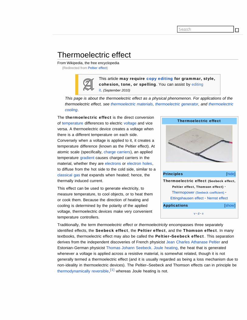
The thermoelectric effect is the direct conversionof temperature differences to electric voltage and viceversa. A thermoelectric device creates a voltage whenthere is a different temperature on each side.Conversely when a voltage is applied to it, it creates atemperature difference (known as the Peltier effect). Atatomic scale (specifically, charge carriers), an appliedtemperature gradient causes charged carriers in thematerial, whether they are electrons or electron holes,to diffuse from the hot side to the cold side, similar to aclassical gas that expands when heated; hence, thethermally induced current.
This effect can be used to generate electricity, tomeasure temperature, to cool objects, or to heat themor cook them. Because the direction of heating andcooling is determined by the polarity of the appliedvoltage, thermoelectric devices make very convenienttemperature controllers.
Traditionally, the term thermoelectric effect or thermoelectricity encompasses three separatelyidentified effects, the Seebeck effect, the Peltier effect, and the Thomson effect. In manytextbooks, thermoelectric effect may also be called the Peltier–Seebeck effect. This separationderives from the independent discoveries of French physicist Jean Charles Athanase Peltier andEstonian-German physicist Thomas Johann Seebeck. Joule heating, the heat that is generatedwhenever a voltage is applied across a resistive material, is somewhat related, though it is notgenerally termed a thermoelectric effect (and it is usually regarded as being a loss mechanism due tonon-ideality in thermoelectric devices). The Peltier–Seebeck and Thomson effects can in principle bethermodynamically reversible,[1] whereas Joule heating is not.
The Seebeck effect is the conversion of temperature differences directly into electricity.
Seebeck discovered that a compass needle would be deflected when a closed loop was formed oftwo metals joined in two places with a temperature difference between the junctions. This is becausethe metals respond differently to the temperature difference, which creates a current loop, whichproduces a magnetic field. Seebeck, however, at this time did not recognize there was an electriccurrent involved, so he called the phenomenon the thermomagnetic effect, thinking that the twometals became magnetically polarized by the temperature gradient. The Danish physicist HansChristian Ørsted played a vital role in explaining and conceiving the term "thermoelectricity".
The effect is that a voltage, the thermoelectric EMF, is created in the presence of a temperaturedifference between two different metals or semiconductors. This causes a continuous current in theconductors if they form a complete loop. The voltage created is of the order of several microvolts perkelvin difference. One such combination, copper-constantan, has a Seebeck coefficient of 41microvolts per kelvin at room temperature.
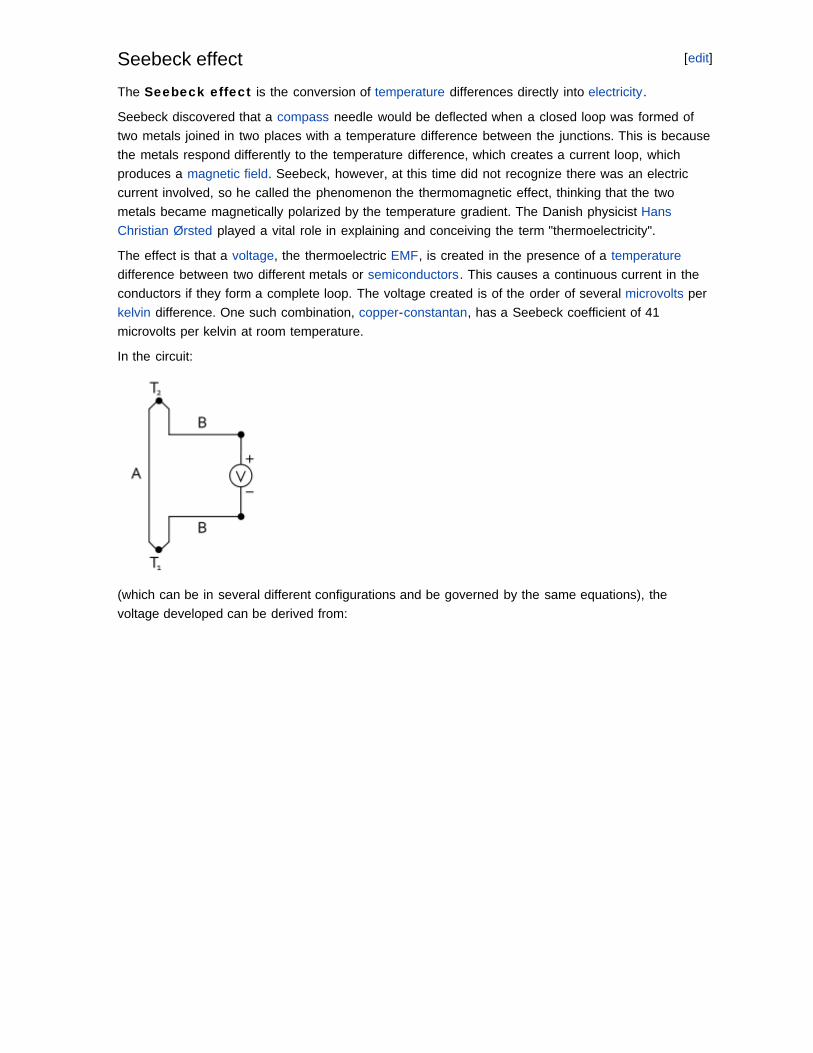
In the circuit:
(which can be in several different configurations and be governed by the same equations), thevoltage developed can be derived from:
[edit]Seebeck effect
SA and SB are the Seebeck coefficients (also called thermoelectric power or thermopower) of themetals A and B as a function of temperature, and T1 and T2 are the temperatures of the twojunctions. The Seebeck coefficients are non-linear as a function of temperature, and depend on theconductors' absolute temperature, material, and molecular structure. If the Seebeck coefficients areeffectively constant for the measured temperature range, the above formula can be approximated as:
The Seebeck effect is commonly used in a device called a thermocouple (because it is made from acoupling or junction of materials, usually metals) to measure a temperature difference directly or tomeasure an absolute temperature by setting one end to a known temperature. A metal of unknowncomposition can be classified by its thermoelectric effect if a metallic probe of known composition,kept at a constant temperature, is held in contact with it. Industrial quality control instruments use thisSeebeck effect to identify metal alloys. This is known as thermoelectric alloy sorting.
Several thermocouples connected in series are called a thermopile, which is sometimes constructedin order to increase the output voltage since the voltage induced over each individual couple is small.
This is also the principle at work behind thermoelectric generators (such as radioisotopethermoelectric generators or RTGs) which are used for creating power from heat differentials.
The Seebeck effect is due to two effects: charge carrier diffusion and phonon drag (described below).
The thermopower, thermoelectric power, or Seebeck coefficient of a material measures themagnitude of an induced thermoelectric voltage in response to a temperature difference across thatmaterial. The thermopower has units of (V/K), though in practice it is more common to use microvoltsper kelvin. Values in the hundreds of μV/K, negative or positive, are typical of good thermoelectricmaterials. The term thermopower is a misnomer since it measures the voltage or electric fieldinduced in response to a temperature difference, not the electric power. An applied temperaturedifference causes charged carriers in the material, whether they are electrons or holes, to diffusefrom the hot side to the cold side, similar to a classical gas that expands when heated. Mobilecharged carriers migrating to the cold side leave behind their oppositely charged and immobile nucleiat the hot side thus giving rise to a thermoelectric voltage (thermoelectric refers to the fact that thevoltage is created by a temperature difference). Since a separation of charges also creates anelectric potential, the buildup of charged carriers onto the cold side eventually ceases at somemaximum value since there exists an equal amount of charged carriers drifting back to the hot sideas a result of the electric field at equilibrium. Only an increase in the temperature difference canresume a buildup of more charge carriers on the cold side and thus lead to an increase in thethermoelectric voltage. Incidentally the thermopower also measures the entropy per charge carrier inthe material. To be more specific, the partial molar electronic entropy is said to equal the absolutethermoelectric power multiplied by the negative of Faraday's constant.[2]
The thermopower of a material, represented by S (or sometimes by α), depends on the material'stemperature and crystal structure. Typically metals have small thermopowers because most havehalf-filled bands. Electrons (negative charges) and holes (positive charges) both contribute to theinduced thermoelectric voltage thus canceling each other's contribution to that voltage and making itsmall. In contrast, semiconductors can be doped with excess electrons or holes, and thus can havelarge positive or negative values of the thermopower depending on the charge of the excess carriers.The sign of the thermopower can determine which charged carriers dominate the electric transport in
[edit]Thermopower
both metals and semiconductors.
If the temperature difference ΔT between the two ends of a material is small, then the thermopowerof a material is defined (approximately)[3] as:
and a thermoelectric voltage ΔV is seen at the terminals.
This can also be written in relation to the electric field E and the temperature gradient , by theapproximate[3] equation:
In practice one rarely measures the absolute thermopower of the material of interest. This is becauseelectrodes attached to a voltmeter must be placed onto the material in order to measure thethermoelectric voltage. The temperature gradient then also typically induces a thermoelectric voltageacross one leg of the measurement electrodes. Therefore the measured thermopower includes acontribution from the thermopower of the material of interest and the material of the measurementelectrodes.
The measured thermopower is then a contribution from both and can be written as:
Superconductors have zero thermopower since the charged carriers produce no entropy. This allowsa direct measurement of the absolute thermopower of the material of interest, since it is thethermopower of the entire thermocouple as well. In addition, a measurement of the Thomson
coefficient, μ, of a material can also yield the thermopower through the relation:
The thermopower is an important material parameter that determines the efficiency of athermoelectric material. A larger induced thermoelectric voltage for a given temperature gradient willlead to a larger efficiency. Ideally one would want very large thermopower values since only a smallamount of heat is then necessary to create a large voltage. This voltage can then be used to providepower.
Charge carriers in the materials (electrons in metals, electrons and holes in semiconductors, ions inionic conductors) will diffuse when one end of a conductor is at a different temperature to the other.Hot carriers diffuse from the hot end to the cold end, since there is a lower density of hot carriers atthe cold end of the conductor. Cold carriers diffuse from the cold end to the hot end for the samereason.
If the conductor were left to reach thermodynamic equilibrium, this process would result in heat beingdistributed evenly throughout the conductor (see heat transfer). The movement of heat (in the form ofhot charge carriers) from one end to the other is called a heat current. As charge carriers are moving,it is also an electric current.
In a system where both ends are kept at a constant temperature difference (a constant heat currentfrom one end to the other), there is a constant diffusion of carriers. If the rate of diffusion of hot andcold carriers in opposite directions were equal, there would be no net change in charge. However,the diffusing charges are scattered by impurities, imperfections, and lattice vibrations (phonons). If thescattering is energy dependent, the hot and cold carriers will diffuse at different rates. This creates ahigher density of carriers at one end of the material, and the distance between the positive and
[edit]Charge-carrier diffusion

negative charges produces a potential difference; an electrostatic voltage.
This electric field, however, opposes the uneven scattering of carriers, and an equilibrium is reachedwhere the net number of carriers diffusing in one direction is canceled by the net number of carriersmoving in the opposite direction from the electrostatic field. This means the thermopower of amaterial depends greatly on impurities, imperfections, and structural changes (which often varythemselves with temperature and electric field), and the thermopower of a material is a collection ofmany different effects.
Early thermocouples were metallic, but many more recently developed thermoelectric devices aremade from alternating p-type and n-type semiconductor elements connected by metallic interconnectsas pictured in the figures below. Semiconductor junctions are especially common in power generationdevices, while metallic junctions are more common in temperature measurement. Charge flowsthrough the n-type element, crosses a metallic interconnect, and passes into the p-type element. If apower source is provided, the thermoelectric device may act as a cooler, as in the figure to the leftbelow. This is the Peltier effect, described below. Electrons in the n-type element will move oppositethe direction of current and holes in the p-type element will move in the direction of current, bothremoving heat from one side of the device. If a heat source is provided, the thermoelectric devicemay function as a power generator, as in the figure to the right below. The heat source will driveelectrons in the n-type element toward the cooler region, thus creating a current through the circuit.Holes in the p-type element will then flow in the direction of the current. The current can then beused to power a load, thus converting the thermal energy into electrical energy.
Main article: Phonon drag
Phonons are not always in local thermal equilibrium; they move against the thermal gradient. Theylose momentum by interacting with electrons (or other carriers) and imperfections in the crystal. If thephonon-electron interaction is predominant, the phonons will tend to push the electrons to one end ofthe material, losing momentum in the process. This contributes to the already present thermoelectricfield. This contribution is most important in the temperature region where phonon-electron scatteringis predominant. This happens for
where θD is the Debye temperature. At lower temperatures there are fewer phonons available fordrag, and at higher temperatures they tend to lose momentum in phonon-phonon scattering insteadof phonon-electron scattering.
[edit]Phonon drag
Thermoelectric effect - Wikipedia, the free encyclopedia
This region of the thermopower-versus-temperature function is highly variable under a magnetic field.
The Peltier (pronounced /ˈpɛltjeɪ/) effect bears the name of Jean-Charles Peltier, a Frenchphysicist who in 1834 discovered the calorific effect of an electric current at the junction of twodifferent metals. When a current is made to flow through the circuit, heat is evolved at the upperjunction (at T2), and absorbed at the lower junction (at T1). The Peltier heat absorbed by the lowerjunction per unit time, is equal to
where π is the Peltier coefficient ΠAB of the entire thermocouple, and ΠA and ΠB are thecoefficients of each material. p-type silicon typically has a positive Peltier coefficient (though notabove ~550 K), and n-type silicon is typically negative.
The Peltier coefficients represent how much heat current is carried per unit charge through a givenmaterial. Since charge current must be continuous across a junction, the associated heat flow willdevelop a discontinuity if ΠA and ΠB are different. This causes a non-zero divergence at the junctionand so heat must accumulate or deplete there, depending on the sign of the current. Another way tounderstand how this effect could cool a junction is to note that when electrons flow from a region ofhigh density to a region of low density, this "expansion" causes cooling (as with an ideal gas).
The carriers are attempting to return to the electron equilibrium that existed before the current wasapplied by absorbing energy at one connector and releasing it at the other. The individual couplescan be connected in series to enhance the effect.
An interesting consequence of this effect is that the direction of heat transfer is controlled by thepolarity of the current; reversing the polarity will change the direction of transfer and thus the sign ofthe heat absorbed/evolved.
A Peltier cooler/heater or thermoelectric heat pump is a solid-state active heat pump whichtransfers heat from one side of the device to the other. Peltier cooling is also called thermo-electriccooling (TEC).
The Thomson effect was predicted and subsequently experimentally observed by WilliamThomson (Lord Kelvin) in 1851. It describes the heating or cooling of a current-carrying conductorwith a temperature gradient.
Any current-carrying conductor (except for a superconductor), with a temperature difference betweentwo points, will either absorb or emit heat, depending on the material.
If a current density J is passed through a homogeneous conductor, heat production per unit volumeis:
where
ρ is the resistivity of the material
dT/dx is the temperature gradient along the wire
μ is the Thomson coefficient.
The first term ρ J² is simply the Joule heating, which is not reversible.
The second term is the Thomson heat, which changes sign when J changes direction.
[edit]Peltier effect
[edit]Thomson effect
Thermoelectric effect - Wikipedia, the free encyclopedia
In metals such as zinc and copper, which have a hotter end at a higher potential and a cooler end ata lower potential, when current moves from the hotter end to the colder end, it is moving from a highto a low potential, so there is an evolution of heat. This is called the positive Thomson effect.
In metals such as cobalt, nickel, and iron, which have a cooler end at a higher potential and a hotterend at a lower potential, when current moves from the hotter end to the colder end, it is moving froma low to a high potential, there is an absorption of heat. This is called the negative Thomsoneffect.
The Thomson coefficient is unique among the three main thermoelectric coefficients because it is theonly thermoelectric coefficient directly measurable for individual materials. The Peltier and Seebeckcoefficients can only be determined for pairs of materials. Thus, there is no direct experimentalmethod to determine an absolute Seebeck coefficient (i.e. thermopower) or absolute Peltier coefficientfor an individual material. However, as mentioned elsewhere in this article there are two equations,the Thomson relations, also known as the Kelvin relations (see below), relating the threethermoelectric coefficients. Therefore, only one can be considered unique.
If the Thomson coefficient of a material is measured over a wide temperature range, includingtemperatures close to zero, one can then integrate the Thomson coefficient over the temperaturerange using the Kelvin relations to determine the absolute (i.e. single-material) values for the Peltierand Seebeck coefficients. In principle, this need only be done for one material, since all other valuescan be determined by measuring pairwise Seebeck coefficients in thermocouples containing thereference material and then adding back the absolute thermoelecric power (thermopower) of thereference material.
It is commonly asserted that lead has a zero Thomson effect. While it is true that the thermoelectriccoefficients of lead are small, they are in general non-zero. The Thomson coefficient of lead has beenmeasured over a wide temperature range and has been integrated to calculate the absolutethermoelectric power (thermopower) of lead as a function of temperature.[4]
Unlike lead, the thermoelectric coefficients of all known superconductors are zero.
The Seebeck effect is a combination of the Peltier and Thomson effects. In 1854 Thomson found tworelationships, now called the Thomson or Kelvin relationships, between the correspondingcoefficients. The absolute temperature T, the Peltier coefficient Π and Seebeck coefficient S arerelated by the second Thomson relation
which predicted the Thomson effect before it was actually formalized. These are related to theThomson coefficient μ by the first Thomson relation
Thomson's theoretical treatment of thermoelectricity is remarkable in the fact that it is probably thefirst attempt to develop a reasonable theory of irreversible thermodynamics (non-equilibriumthermodynamics). This occurred at about the time that Clausius, Thomson, and others wereintroducing and refining the concept of entropy.
The figure of merit for thermoelectric devices is defined as
,
where σ is the electrical conductivity, κ is the thermal conductivity, and S is the Seebeck coefficient
[edit]The Thomson relationships
[edit]Figure of merit
or thermopower (conventionally in μV/K). This is more commonly expressed as the dimensionlessfigure of merit ZT by multiplying it with the average temperature ((T2 + T1) / 2). Greater values of ZTindicate greater thermodynamic efficiency, subject to certain provisions, particularly the requirementthat the two materials of the couple have similar Z values. ZT is therefore a very convenient figure forcomparing the potential efficiency of devices using different materials. Values of ZT=1 are consideredgood, and values of at least the 3–4 range are considered to be essential for thermoelectrics tocompete with mechanical generation and refrigeration in efficiency. To date, the best reported ZTvalues have been in the 2–3 range.[5][6][7] Much research in thermoelectric materials has focusedon increasing the Seebeck coefficient and reducing the thermal conductivity, especially bymanipulating the nanostructure of the materials.
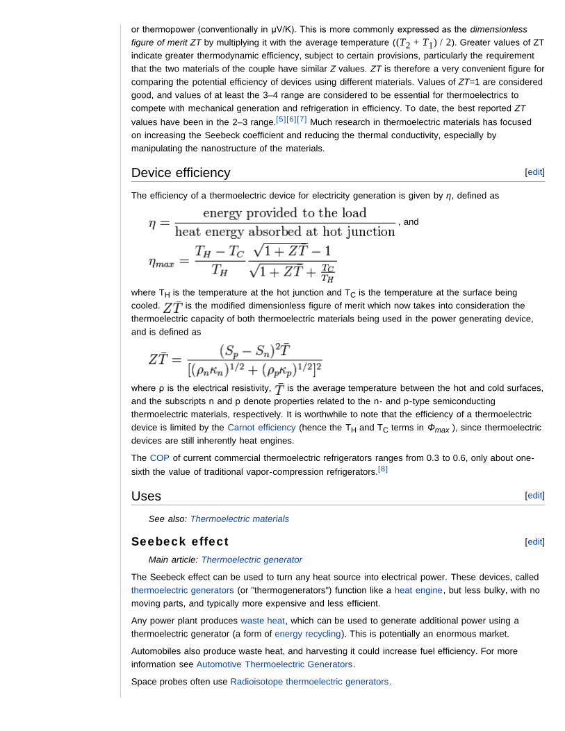
The efficiency of a thermoelectric device for electricity generation is given by η, defined as
, and
where TH is the temperature at the hot junction and TC is the temperature at the surface beingcooled. is the modified dimensionless figure of merit which now takes into consideration thethermoelectric capacity of both thermoelectric materials being used in the power generating device,and is defined as
where ρ is the electrical resistivity, is the average temperature between the hot and cold surfaces,and the subscripts n and p denote properties related to the n- and p-type semiconductingthermoelectric materials, respectively. It is worthwhile to note that the efficiency of a thermoelectricdevice is limited by the Carnot efficiency (hence the TH and TC terms in Φmax ), since thermoelectricdevices are still inherently heat engines.
The COP of current commercial thermoelectric refrigerators ranges from 0.3 to 0.6, only about one-sixth the value of traditional vapor-compression refrigerators.[8]
See also: Thermoelectric materials
Main article: Thermoelectric generator
The Seebeck effect can be used to turn any heat source into electrical power. These devices, calledthermoelectric generators (or "thermogenerators") function like a heat engine, but less bulky, with nomoving parts, and typically more expensive and less efficient.
Any power plant produces waste heat, which can be used to generate additional power using athermoelectric generator (a form of energy recycling). This is potentially an enormous market.
Automobiles also produce waste heat, and harvesting it could increase fuel efficiency. For moreinformation see Automotive Thermoelectric Generators.
Space probes often use Radioisotope thermoelectric generators.
[edit]Device efficiency
[edit]Uses
[edit]Seebeck effect
Solar cells use only the high frequency part of the radiation, while the low frequency heat energy iswasted. Several patents about the use of thermoelectric devices in tandem with solar cells have beenfiled. The idea is to increase the efficiency of the combined solar/thermoelectric system to convert thesolar radiation into useful electricity.
The Peltier effect can be used to create a refrigerator which is compact and has no circulating fluid ormoving parts. For more information see Peltier cooler.
Thermocouples and thermopiles are commonly used to measure temperatures. They use theSeebeck effect. More precisely, they do not directly measure temperature, they measure temperaturedifferences between the probe and the voltmeter at the other end of the wires. The temperature ofthe voltmeter, usually the same as room temperature, can be measured separately using "coldjunction compensation" techniques.
Heat transferJoule's lawsPyroelectricity – the creation of an electric field in a crystal after uniform heatingSpintronicsThermionic emissionThermoacoustic refrigerationThermodiffusionThermoelectric coolingThermoelectricityThermoelectric generatorThermopileThermopower
[edit]Peltier effect
[edit]Temperature measurement
See also
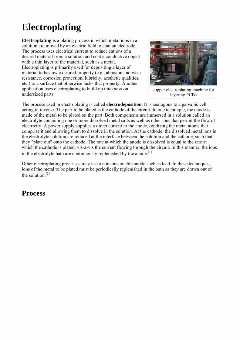
copper electroplating machine for
layering PCBs
ElectroplatingElectroplating is a plating process in which metal ions in a solution are moved by an electric field to coat an electrode. The process uses electrical current to reduce cations of a desired material from a solution and coat a conductive object with a thin layer of the material, such as a metal. Electroplating is primarily used for depositing a layer of material to bestow a desired property (e.g., abrasion and wear resistance, corrosion protection, lubricity, aesthetic qualities, etc.) to a surface that otherwise lacks that property. Another application uses electroplating to build up thickness on undersized parts.
The process used in electroplating is called electrodeposition. It is analogous to a galvanic cell acting in reverse. The part to be plated is the cathode of the circuit. In one technique, the anode is made of the metal to be plated on the part. Both components are immersed in a solution called an electrolyte containing one or more dissolved metal salts as well as other ions that permit the flow of electricity. A power supply supplies a direct current to the anode, oxidizing the metal atoms that comprise it and allowing them to dissolve in the solution. At the cathode, the dissolved metal ions in the electrolyte solution are reduced at the interface between the solution and the cathode, such that they "plate out" onto the cathode. The rate at which the anode is dissolved is equal to the rate at which the cathode is plated, vis-a-vis the current flowing through the circuit. In this manner, the ions in the electrolyte bath are continuously replenished by the anode.[1]
Other electroplating processes may use a nonconsumable anode such as lead. In these techniques, ions of the metal to be plated must be periodically replenished in the bath as they are drawn out of the solution.[2]
Process
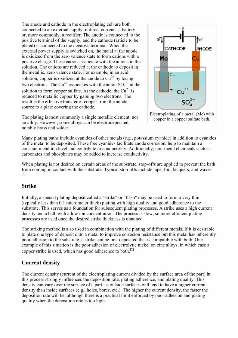
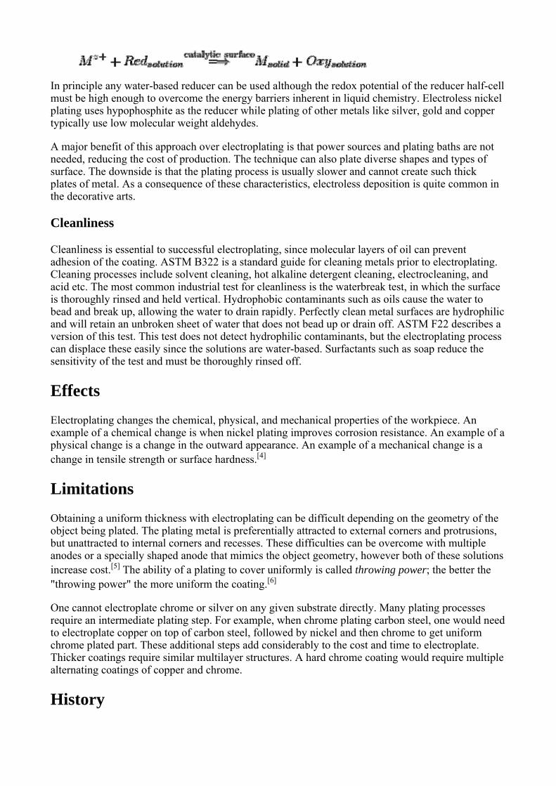
Electroplating of a metal (Me) with
copper in a copper sulfate bath.
The anode and cathode in the electroplating cell are both connected to an external supply of direct current - a battery or, more commonly, a rectifier. The anode is connected to the positive terminal of the supply, and the cathode (article to be plated) is connected to the negative terminal. When the external power supply is switched on, the metal at the anode is oxidized from the zero valence state to form cations with a positive charge. These cations associate with the anions in the solution. The cations are reduced at the cathode to deposit in the metallic, zero valence state. For example, in an acid solution, copper is oxidized at the anode to Cu2+ by losing two electrons. The Cu2+ associates with the anion SO4
2- in the solution to form copper sulfate. At the cathode, the Cu2+ is reduced to metallic copper by gaining two electrons. The result is the effective transfer of copper from the anode source to a plate covering the cathode.
The plating is most commonly a single metallic element, not an alloy. However, some alloys can be electrodeposited, notably brass and solder.
Many plating baths include cyanides of other metals (e.g., potassium cyanide) in addition to cyanides of the metal to be deposited. These free cyanides facilitate anode corrosion, help to maintain a constant metal ion level and contribute to conductivity. Additionally, non-metal chemicals such as carbonates and phosphates may be added to increase conductivity.
When plating is not desired on certain areas of the substrate, stop-offs are applied to prevent the bath from coming in contact with the substrate. Typical stop-offs include tape, foil, lacquers, and waxes.[3]
Strike
Initially, a special plating deposit called a "strike" or "flash" may be used to form a very thin(typically less than 0.1 micrometer thick) plating with high quality and good adherence to the substrate. This serves as a foundation for subsequent plating processes. A strike uses a high current density and a bath with a low ion concentration. The process is slow, so more efficient plating processes are used once the desired strike thickness is obtained.
The striking method is also used in combination with the plating of different metals. If it is desirable to plate one type of deposit onto a metal to improve corrosion resistance but this metal has inherently poor adhesion to the substrate, a strike can be first deposited that is compatible with both. One example of this situation is the poor adhesion of electrolytic nickel on zinc alloys, in which case a copper strike is used, which has good adherence to both.[2]
Current density
The current density (current of the electroplating current divided by the surface area of the part) in this process strongly influences the deposition rate, plating adherence, and plating quality. This density can vary over the surface of a part, as outside surfaces will tend to have a higher current density than inside surfaces (e.g., holes, bores, etc.). The higher the current density, the faster the deposition rate will be, although there is a practical limit enforced by poor adhesion and plating quality when the deposition rate is too high.
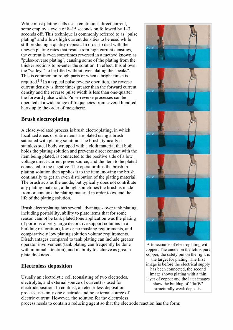
A timecourse of electroplating with copper. The anode on the left is pure copper, the safety pin on the right is
the target for plating. The first image is before the electrical supply
has been connected, the second image shows plating with a thin
layer of copper and the later images show the buildup of "fluffy" structurally weak deposits.
While most plating cells use a continuous direct current, some employ a cycle of 8–15 seconds on followed by 1–3 seconds off. This technique is commonly referred to as "pulse plating" and allows high current densities to be used while still producing a quality deposit. In order to deal with the uneven plating rates that result from high current densities, the current is even sometimes reversed in a method known as "pulse-reverse plating", causing some of the plating from the thicker sections to re-enter the solution. In effect, this allows the "valleys" to be filled without over-plating the "peaks". This is common on rough parts or when a bright finish is required.[3] In a typical pulse reverse operation, the reverse current density is three times greater than the forward current density and the reverse pulse width is less than one-quarter the forward pulse width. Pulse-reverse processes can be operated at a wide range of frequencies from several hundred hertz up to the order of megahertz.
Brush electroplating
A closely-related process is brush electroplating, in which localized areas or entire items are plated using a brush saturated with plating solution. The brush, typically a stainless steel body wrapped with a cloth material that both holds the plating solution and prevents direct contact with the item being plated, is connected to the positive side of a low voltage direct-current power source, and the item to be plated connected to the negative. The operator dips the brush in plating solution then applies it to the item, moving the brush continually to get an even distribution of the plating material. The brush acts as the anode, but typically does not contribute any plating material, although sometimes the brush is made from or contains the plating material in order to extend the life of the plating solution.
Brush electroplating has several advantages over tank plating,including portability, ability to plate items that for some reason cannot be tank plated (one application was the plating of portions of very large decorative support columns in a building restoration), low or no masking requirements, and comparatively low plating solution volume requirements. Disadvantages compared to tank plating can include greater operator involvement (tank plating can frequently be done with minimal attention), and inability to achieve as great a plate thickness.
Electroless deposition
Usually an electrolytic cell (consisting of two electrodes, electrolyte, and external source of current) is used for electrodeposition. In contrast, an electroless deposition process uses only one electrode and no external source of electric current. However, the solution for the electroless process needs to contain a reducing agent so that the electrode reaction has the form:
In principle any water-based reducer can be used although the redox potential of the reducer half-cell must be high enough to overcome the energy barriers inherent in liquid chemistry. Electroless nickel plating uses hypophosphite as the reducer while plating of other metals like silver, gold and copper typically use low molecular weight aldehydes.
A major benefit of this approach over electroplating is that power sources and plating baths are not needed, reducing the cost of production. The technique can also plate diverse shapes and types of surface. The downside is that the plating process is usually slower and cannot create such thick plates of metal. As a consequence of these characteristics, electroless deposition is quite common in the decorative arts.
Cleanliness
Cleanliness is essential to successful electroplating, since molecular layers of oil can prevent adhesion of the coating. ASTM B322 is a standard guide for cleaning metals prior to electroplating. Cleaning processes include solvent cleaning, hot alkaline detergent cleaning, electrocleaning, and acid etc. The most common industrial test for cleanliness is the waterbreak test, in which the surface is thoroughly rinsed and held vertical. Hydrophobic contaminants such as oils cause the water to bead and break up, allowing the water to drain rapidly. Perfectly clean metal surfaces are hydrophilic and will retain an unbroken sheet of water that does not bead up or drain off. ASTM F22 describes a version of this test. This test does not detect hydrophilic contaminants, but the electroplating process can displace these easily since the solutions are water-based. Surfactants such as soap reduce the sensitivity of the test and must be thoroughly rinsed off.
Effects
Electroplating changes the chemical, physical, and mechanical properties of the workpiece. An example of a chemical change is when nickel plating improves corrosion resistance. An example of a physical change is a change in the outward appearance. An example of a mechanical change is a change in tensile strength or surface hardness.[4]
Limitations
Obtaining a uniform thickness with electroplating can be difficult depending on the geometry of the object being plated. The plating metal is preferentially attracted to external corners and protrusions, but unattracted to internal corners and recesses. These difficulties can be overcome with multiple anodes or a specially shaped anode that mimics the object geometry, however both of these solutionsincrease cost.[5] The ability of a plating to cover uniformly is called throwing power; the better the "throwing power" the more uniform the coating.[6]
One cannot electroplate chrome or silver on any given substrate directly. Many plating processes require an intermediate plating step. For example, when chrome plating carbon steel, one would need to electroplate copper on top of carbon steel, followed by nickel and then chrome to get uniform chrome plated part. These additional steps add considerably to the cost and time to electroplate. Thicker coatings require similar multilayer structures. A hard chrome coating would require multiple alternating coatings of copper and chrome.
History
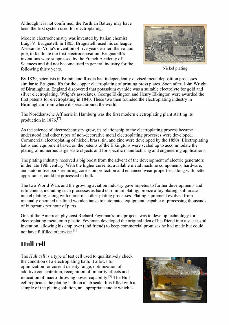
Nickel plating
Although it is not confirmed, the Parthian Battery may have been the first system used for electroplating.
Modern electrochemistry was invented by Italian chemist Luigi V. Brugnatelli in 1805. Brugnatelli used his colleague Alessandro Volta's invention of five years earlier, the voltaic pile, to facilitate the first electrodeposition. Brugnatelli's inventions were suppressed by the French Academy of Sciences and did not become used in general industry for the following thirty years.
By 1839, scientists in Britain and Russia had independently devised metal deposition processes similar to Brugnatelli's for the copper electroplating of printing press plates. Soon after, John Wright of Birmingham, England discovered that potassium cyanide was a suitable electrolyte for gold and silver electroplating. Wright's associates, George Elkington and Henry Elkington were awarded the first patents for electroplating in 1840. These two then founded the electroplating industry in Birmingham from where it spread around the world.
The Norddeutsche Affinerie in Hamburg was the first modern electroplating plant starting its production in 1876.[7]
As the science of electrochemistry grew, its relationship to the electroplating process became understood and other types of non-decorative metal electroplating processes were developed. Commercial electroplating of nickel, brass, tin, and zinc were developed by the 1850s. Electroplatingbaths and equipment based on the patents of the Elkingtons were scaled up to accommodate the plating of numerous large scale objects and for specific manufacturing and engineering applications.
The plating industry received a big boost from the advent of the development of electric generatorsin the late 19th century. With the higher currents, available metal machine components, hardware, and automotive parts requiring corrosion protection and enhanced wear properties, along with better appearance, could be processed in bulk.
The two World Wars and the growing aviation industry gave impetus to further developments and refinements including such processes as hard chromium plating, bronze alloy plating, sulfamate nickel plating, along with numerous other plating processes. Plating equipment evolved from manually operated tar-lined wooden tanks to automated equipment, capable of processing thousands of kilograms per hour of parts.
One of the American physicist Richard Feynman's first projects was to develop technology for electroplating metal onto plastic. Feynman developed the original idea of his friend into a successful invention, allowing his employer (and friend) to keep commercial promises he had made but could not have fulfilled otherwise.[8]
Hull cell
The Hull cell is a type of test cell used to qualitatively check the condition of a electroplating bath. It allows for optimization for current density range, optimization of additive concentration, recognition of impurity effects and indication of macro-throwing power capability.[9] The Hull cell replicates the plating bath on a lab scale. It is filled with a sample of the plating solution, an appropriate anode which is
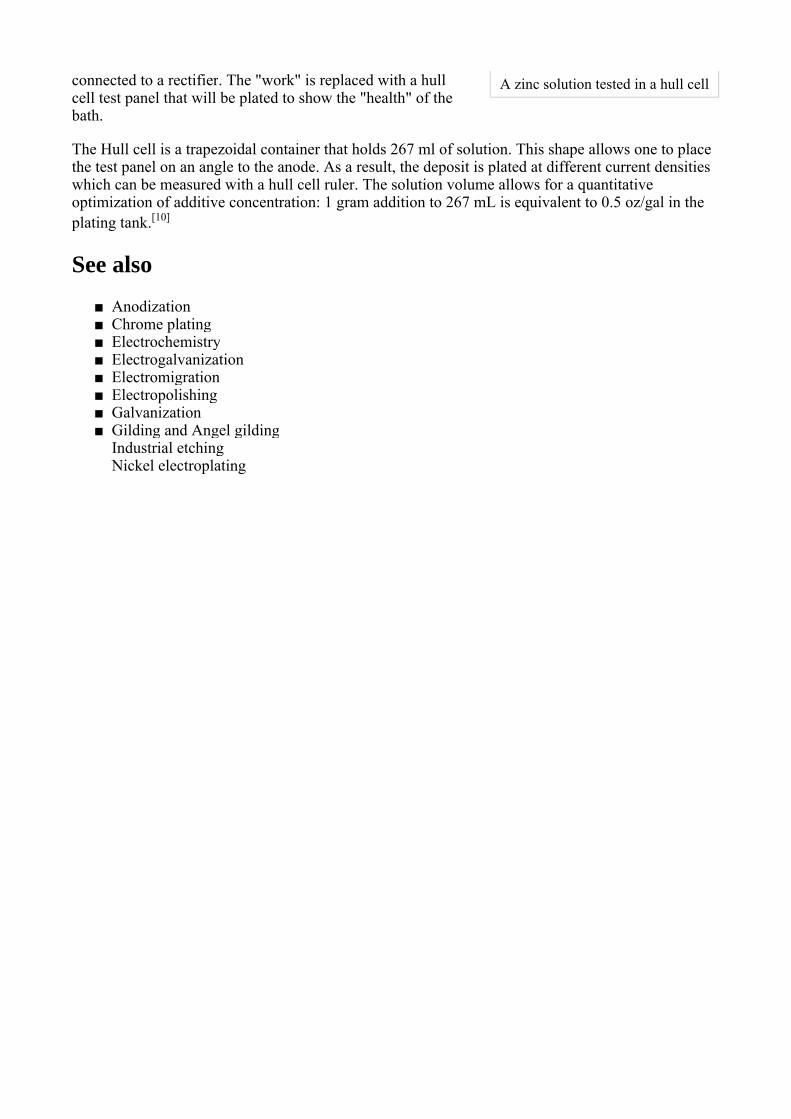
A zinc solution tested in a hull cellconnected to a rectifier. The "work" is replaced with a hull cell test panel that will be plated to show the "health" of the bath.
The Hull cell is a trapezoidal container that holds 267 ml of solution. This shape allows one to place the test panel on an angle to the anode. As a result, the deposit is plated at different current densities which can be measured with a hull cell ruler. The solution volume allows for a quantitative optimization of additive concentration: 1 gram addition to 267 mL is equivalent to 0.5 oz/gal in the plating tank.[10]
See also
Anodization■Chrome plating■Electrochemistry■Electrogalvanization■Electromigration■Electropolishing■Galvanization■Gilding and Angel gilding■Industrial etchingNickel electroplating


![Thermoelectric Seebeck and Peltier effects of single ...carbonlett.org/Upload/files/CARBONLETT/[008-015]-04.pdf · 8 Thermoelectric Seebeck and Peltier effects of single walled carbon](https://img.dokumen.tips/doc/110x75/5b546c047f8b9a1f648cff2d/thermoelectric-seebeck-and-peltier-effects-of-single-008-015-04pdf-8-thermoelectric.jpg)