Embed Size (px)
Citation preview
Visit our Web site at:
http://www.thermo.com/tcProduct Service Information, Applications Notes, MSDS Forms, e-mail.
Voice Info: (800) 258-0830
Installation Operation
Basic Maintenance
Label 1
Label 2
Thermo ScientificNESLAB ThermoFlexTM
Recirculating Chillers (Deluxe Controller)Thermo Scientific Manual P/N U00939 Rev. 10/22/09
Thermo Fisher Scientific
25 Nimble Hill RoadNewington, NH 03801Tel : (800) 258-0830 or(603) 436-9444Fax : (603) 436-8411www.thermo.com/tc
Sales, Service, and Customer Support
25 Nimble Hill RoadNewington, NH 03801Tel: (800) 258-0830 Sales: 8:00 am to 5:00 pmService and Support: 8:00 am to 6:00 pm Monday through Friday (Eastern Time)Fax: (603) [email protected]
Dieselstrasse 4 D-76227 Karlsruhe, Germany Tel : +49 (0) 721 4094 444 Fax : +49 (0) 721 4094 [email protected]
Building 6, No. 27Xin Jinqiao Rd., Shanghai 201206Tel : +86(21) 68654588Fax : +86(21) [email protected]
Ion Path, Road Three, Winsford, Cheshire, CW73GA, United KingdomPhone: +44 (0)8706 099254Fax: +44 (0)1606 548103
Statement of Copyright Copyright © 2009 Thermo Fisher Scientific. All rights reserved. This manual is copyrighted by Thermo Fisher Scientific. Users are forbidden to reproduce, republish, redistribute, or resell any materials from this manual in either machine-readable form or any other form.
NESLAB ThermoFlex Thermo Scientific
Contents
Preface ...................................................................................................................... i Compliance ..............................................................................................................i WEEE ......................................................................................................................i After-Sale Support .................................................................................................ii Unpacking ...............................................................................................................ii Warranty ..................................................................................................................ii Feedback ..................................................................................................................ii
Section 1 Safety ..................................................................................1-1 Warnings ..............................................................................................................1-1
Section 2 General Information ................................................................2-1 Description .........................................................................................................2-1 Specifications ......................................................................................................2-1
Section 3 Installation ...........................................................................3-1 Site Requirements ..............................................................................................3-1 Electrical Requirements ....................................................................................3-2 Hard Wire Installation .......................................................................................3-7 Plumbing Requirements ....................................................................................3-8 Process Fluid Requirements ...........................................................................3-10 Compatibility with Acceptable Fluids ...........................................................3-11 Process Water Quality - Standards and Recommendations ......................3-12 Initial Filling Requirements ............................................................................3-13 Fluid Top Off ...................................................................................................3-14 Water Treatment Kit (North America Only) ...............................................3-14 Facility Water Requirements (water-cooled units) ......................................3-15 Facility Water Requirements - Standards and Recommendations ............3-17 Section 4 Operation .............................................................................4-1 Deluxe Controller ..............................................................................................4-1 Setup ....................................................................................................................4-2 Initial Start Up ....................................................................................................4-2 Daily Start Up .....................................................................................................4-3 Process Fluid Temperature Display ................................................................4-4 SETPOINT ........................................................................................................4-5 Status Display .....................................................................................................4-6 MENU Display ..................................................................................................4-7 Main Menu Tree .................................................................................................4-8 Shut Down ........................................................................................................4-20
NESLAB ThermoFlex
Contents
Thermo Scientific
Section 5 Additional Options/Accessories ................................................5-1 AutoRefill .........................................................................................................5-1 InternalDICartridge ........................................................................................5-2 P1P2T1PumpPressureRelief Valve(InternalConfiguration) ............... 5-3 P1P2T1PumpPressureRelief Valve(ExternalConfiguration) .............. 5-4 FlowControlwithFlowReadout ....................................................................5-5 P1P2T1PumpPressureRelief withFlowReadout ................................... 5-5 AntiDrainback ...................................................................................................5-6 SEMI ....................................................................................................................5-6 OtherAccessories ............................................................................................5-10
Section 6 Preventive Maintenance............................................................................... 6-1 PreventiveMaintenanceTimer .......................................................................6-1 DIAGONTICS ..................................................................................................6-2 FluidBagFilter ...................................................................................................6-3 FluidDiffuser .....................................................................................................6-3 ReservoirCleaning .............................................................................................6-4 CondenserFilter .................................................................................................6-5 DIFilter(Optional) ..........................................................................................6-7 PreventiveMaintenanceMessages ..................................................................6-8
Section 7 Troubleshooting .....................................................................7-1 Messages ..............................................................................................................7-1 FaultsandWarnings ..........................................................................................7-1 SafetyAlarm .......................................................................................................7-9 Error ..................................................................................................................7-10 MESSAGES......................................................................................................7-11 Checklist ............................................................................................................7-12 TUNING ..........................................................................................................7-14
Section 8 Additional Information ............................................................8-1 Draining ...............................................................................................................8-1 CALIBRATION ................................................................................................8-3 WettedMaterials .................................................................................................8-4 Shipment/Storage ..............................................................................................8-4
Appendix A CountrySpecific230VAC,50Hz,1ØRequirements
Appendix B VoltageConfigurationInstructions
Appendix C SerialCommunications
Appendix D AnalogI/OandRemoteSensor
WARRANTY
Pre
ss
.
The
cont
rolle
r will
dis
play
QU
ICK
STA
RT.
Not
e: B
efor
e pr
ocee
ding
, if t
he u
nit i
s eq
uipp
ed w
ith a
de
ioni
zatio
n fi l
ter c
artri
dge,
refe
r to
Sec
tion
5 in
the
man
ual f
or
inst
alla
tion.
Plea
se s
ee re
vers
e si
de fo
r add
ition
al in
form
atio
n.
See
Fig
ure
A.
MIN
LEVE
L
MA
XLE
VEL
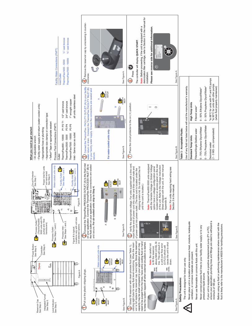
Slo
wly
fi ll
rese
rvoi
r with
cle
an p
roce
ss fl
uid
(see
Tab
le 1
), ut
ilizi
ng s
ight
tube
for e
asy fl u
id le
vel m
onito
ring.
Whe
n th
e re
ser-
voir
is fu
ll re
plac
e th
e re
serv
oir c
ap, h
and
tight
. Sin
ce th
e re
serv
oir
capa
city
may
be
smal
l com
pare
d to
you
r app
licat
ion
and
air m
ay
need
to b
e pu
rged
from
the
lines
, hav
e ex
tra c
oolin
g fl u
id o
n ha
nd
to k
eep
the
syst
em to
pped
off
whe
n ex
tern
al c
ircul
atio
n is
sta
rted.
Pul
l out
the
plas
tic s
hipp
ing
plug
s. R
emov
e th
e re
serv
oir c
ap b
y un
scre
win
g it
coun
ter-
cloc
kwis
e.
Ver
ify th
e ap
prop
riate
vol
tage
. For
uni
ts s
uppl
ied
with
a li
ne c
ord,
in
sert
fem
ale
end
of p
ower
cor
d in
to c
hille
r and
then
inse
rt m
ale
end
of p
ower
cor
d in
to p
ower
out
let.
(The
line
cor
d is
loca
ted
unde
r the
sh
ippi
ng c
rate
’s li
d. D
o no
t dis
card
the
lid
until
the
cord
is lo
cate
d.)
Con
nect
the
Ther
moF
lex
FA
CIL
ITY
OU
TLE
T (A
) to
your
faci
lity
wat
er re
turn
or d
rain
. C
onne
ct th
e Th
erm
oFle
x FA
CIL
ITY
INLE
T (B
) to
you
r fac
ility
wat
er s
uppl
y. E
nsur
e th
e co
nnec
tions
are
sea
led
and
secu
re.
Wat
er-c
oole
d un
its o
nly
Safe
ty P
reca
utio
ns:
The
unit
is d
esig
ned
for i
ndoo
r use
onl
y.
Nev
er p
lace
uni
t in
a lo
catio
n w
here
exc
essi
ve h
eat,
moi
stur
e, in
adeq
uate
ve
ntila
tion,
or c
orro
sive
mat
eria
ls a
re p
rese
nt.
Nev
er u
se fl
amm
able
or c
orro
sive
fl ui
ds w
ith th
is u
nit.
Nev
er c
onne
ct p
roce
ss fl
uid
lines
to y
our f
acili
ty w
ater
sup
ply
or to
any
pr
essu
rized
liqu
id s
ourc
e.
If yo
ur u
nit i
s eq
uipp
ed w
ith a
pos
itive
dis
plac
emen
t pum
p (P
1 or
P2)
, en
sure
you
r app
licat
ion
plum
bing
line
s an
d fi t
tings
are
rate
d to
with
stan
d a
min
imum
of 1
85 p
si.
Bef
ore
usin
g an
y fl u
id o
r per
form
ing
mai
nten
ance
whe
re c
onta
ct w
ith th
e fl u
id is
like
ly re
fer t
o th
e m
anuf
actu
rer’s
MS
DS
for h
andl
ing
prec
autio
ns.
For w
ater
-coo
led
units
onl
y.
See
Fig
ure
B.
See
Fig
ure
B.
See
Fig
ure
B.
See
Fig
ure
B.
See
Fig
ure
A.
Con
nect
the
Ther
moF
lex
PR
OC
ES
S O
UTL
ET
(A) t
o th
e fl u
id in
let
on y
our a
pplic
atio
n. C
onne
ct th
e Th
erm
oFle
x P
RO
CE
SS
INLE
T (B
) to
the fl u
id o
utle
t on
your
app
licat
ion.
Ens
ure
the
conn
ectio
ns a
re s
eale
d an
d se
cure
. For
air-
cool
ed u
nits
ski
p to
Ste
p 4.
Pla
ce th
e ci
rcui
t pro
tect
or to
the
on (
I ) p
ositi
on.
B
A
B
A
PRO
CES
SIN
LET
PRO
CES
SO
UTL
ET
FAC
ILIT
YIN
LET
FAC
ILIT
YO
UTL
ET
FAC
ILIT
YIN
LET
FAC
ILIT
YO
UTL
ET
Not
e: B
e ca
refu
l not
to
fi ll
the
rese
rvoi
r ab
ove
MA
X L
EV
EL fi l
l lin
e. T
his
will
resu
lt in
a
unit
over
fl ow
err
or
(O F
LO) w
hich
will
ca
use
the
unit
to s
hut
dow
n.
Not
e: T
herm
oFle
x900
-500
0 un
its e
quip
ped
with
the
Varia
ble
Volta
ge o
r Glo
bal V
olta
ge
optio
n ha
ve a
vol
tage
confi g
urat
ion
pane
l lo
cate
d be
hind
an
acce
ss p
anel
on
the
rear
of
the
unit.
Ref
er to
the
Volta
ge In
stru
ctio
n S
heet
shi
pped
with
the
unit,
or s
ee m
anua
l A
ppen
dix
B.
Not
e: F
or u
nits
requ
iring
har
d w
iring
see
S
ectio
n 3
in th
e m
anua
l.
ente
r
esc
+ -
QU
ICK
ST
AR
T
UN
ITS
Se
tpo
int
20
TE
MP
ER
AT
UR
E
PR
ES
SU
RE
Pro
cess
Out
let -
S
ee S
teps
1 a
nd 2
.
Pro
cess
Out
let -
(T
herm
oFle
x900
-50
00 u
nits
with
PD
pu
mps
and
fl o
w
trans
duce
rs)
Circ
uit P
rote
ctor
S
ee S
tep
7.
Pow
er In
let f
or u
nits
no
t har
d-w
ired
See
Ste
p 6.
Pro
cess
Inle
t -S
ee S
teps
1 a
nd 2
.
Figu
re B
is ty
pica
l. Lo
catio
ns v
ary
with
uni
t siz
e an
d se
lect
ed o
ptio
ns.
Faci
lity
Inle
tS
ee S
teps
1 a
nd 3
.
Faci
lity
Out
let
See
Ste
ps 1
and
3.
Wat
er-c
oole
d un
its o
nly
Wha
t you
nee
d to
get
sta
rted
:• A
n ad
just
able
wre
nch
• Fac
ility
wat
er s
uppl
y an
d re
turn
(wat
er-c
oole
d un
its)
• App
ropr
iate
hos
e or
plu
mbi
ng• A
ppro
pria
te s
ize
clam
ps o
r con
nect
ion
type
• Tefl
on®
Tap
e or
app
ropr
iate
sea
lant
Figu
re B
Con
trolle
r S
ee S
tep
8.
Pow
er B
utto
nS
ee S
tep
8.
Inte
grat
ed F
unne
lS
ee S
tep
5.
Leve
l Ind
icat
orS
ee S
tep
5.
Figu
re A
Res
ervo
ir C
apS
ee S
tep
4.
Pro
cess
Flu
id C
onne
ctio
ns (F
NP
T)O
utle
t Th
erm
oFle
x900
- 10
000
P
1 P
2 T1
1/
2" c
ast b
ronz
eTh
erm
oFle
x350
0 - 5
000
P
3 P
4 3/
4" c
ast b
ronz
eTh
erm
oFle
x750
0 - 1
0000
P
3 P
5
1" w
roug
ht c
oppe
rIn
let -
Sam
e si
ze a
s ou
tlet
al
l uni
ts s
tain
less
ste
el
Faci
lity
Wat
er C
onne
ctio
ns (F
NP
T)In
let/O
utle
tTh
erm
oFle
x140
0 - 5
000
½
” cas
t bro
nze
Ther
moF
lex7
500
- 100
00
¾
” cas
t bro
nze
See
Fig
ure
B.
PRO
CES
SIN
LET
PRO
CES
SO
UTL
ET
See
Fig
ure
A.
Tabl
e 1
- Acc
epta
ble
Flui
ds:
Use
of a
ny fl
uid
not l
iste
d be
low
will
voi
d th
e m
anuf
actu
rer’s
war
rant
y.
Stan
dard
Tem
p U
nits
Hig
h Te
mp
Uni
ts
Filte
red/
Sin
gle
Dis
tille
d w
ater
Fi
ltere
d w
ater
*
0 - 7
5% E
thyl
ene
Gly
col/W
ater
0
- 50%
Eth
ylen
e G
lyco
l/Wat
er*
0 - 7
5% P
ropy
lene
Gly
col/W
ater
0
- 50%
Pro
pyle
ne G
lyco
l/Wat
er*
Dei
oniz
ed w
ater
*t
o 88
°C fo
r uni
ts w
ith P
1 an
d P
2 pu
mps
(1 -
3 MΩ
- cm
, com
pens
ated
) *t
o 90
°C fo
r uni
ts w
ith o
ther
pum
ps
(w
hen fl u
id p
rope
rly m
aint
aine
d)
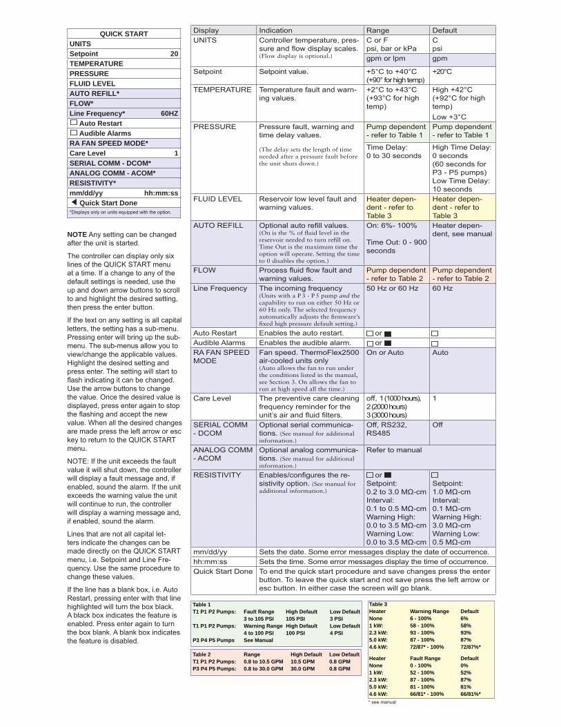
Display Indication Range DefaultUNITS Controller temperature, pres-
sure and fl ow display scales.(Flow display is optional.)
C or Fpsi, bar or kPa
Cpsi
gpm or lpm gpm
Setpoint Setpoint value. +5°C to +40°C(+90° for high temp)
+20°C
TEMPERATURE Temperature fault and warn-ing values.
+2°C to +43°C(+93°C for high temp)
High +42°C (+92°C for high temp)Low +3°C
PRESSURE Pressure fault, warning and time delay values.
(The delay sets the length of time needed after a pressure fault before the unit shuts down.)
Pump dependent - refer to Table 1
Pump dependent - refer to Table 1
Time Delay: 0 to 30 seconds
High Time Delay: 0 seconds (60 seconds for P3 - P5 pumps)Low Time Delay: 10 seconds
FLUID LEVEL Reservoir low level fault and warning values.
Heater depen-dent - refer to Table 3
Heater depen-dent - refer to Table 3
AUTO REFILL Optional auto refi ll values. (On is the % of fl uid level in the reservoir needed to turn refi ll on. Time Out is the maximum time the option will operate. Setting the time to 0 disables the option.)
On: 6%- 100%
Time Out: 0 - 900 seconds
Heater depen-dent, see manual
FLOW Process fl uid fl ow fault and warning values.
Pump dependent - refer to Table 2
Pump dependent - refer to Table 2
Line Frequency The incoming frequency (Units with a P 3 - P 5 pump and the capability to run on either 50 Hz or 60 Hz only. The selected frequency automatically adjusts the fi rmware’s fi xed high pressure default setting.)
50 Hz or 60 Hz 60 Hz
Auto Restart Enables the auto restart. orAudible Alarms Enables the audible alarm. orRA FAN SPEED MODE
Fan speed. ThermoFlex2500 air-cooled units only(Auto allows the fan to run under the conditions listed in the manual, see Section 3. On allows the fan to run at high speed all the time.)
On or Auto Auto
Care Level The preventive care cleaning frequency reminder for the unit’s air and fl uid fi lters.
off, 1 (1000 hours),2 (2000 hours)3 (3000 hours)
1
SERIAL COMM - DCOM
Optional serial communica-tions. (See manual for additional information.)
Off, RS232, RS485
Off
ANALOG COMM - ACOM
Optional analog communica-tions. (See manual for additional information.)
Refer to manual
RESISTIVITY Enables/confi gures the re-sistivity option. (See manual for additional information.)
orSetpoint: 0.2 to 3.0 MΩ-cmInterval: 0.1 to 0.5 MΩ-cmWarning High: 0.0 to 3.5 MΩ-cmWarning Low: 0.0 to 3.5 MΩ-cm
Setpoint: 1.0 MΩ-cmInterval: 0.1 MΩ-cmWarning High: 3.0 MΩ-cmWarning Low: 0.5 MΩ-cm
mm/dd/yy Sets the date. Some error messages display the date of occurrence.hh:mm:ss Sets the time. Some error messages display the time of occurrence.Quick Start Done To end the quick start procedure and save changes press the enter
button. To leave the quick start and not save press the left arrow or esc button. In either case the screen will go blank.
NOTE Any setting can be changed after the unit is started.
The controller can display only six lines of the QUICK START menu at a time. If a change to any of the default settings is needed, use the up and down arrow buttons to scroll to and highlight the desired setting, then press the enter button.
If the text on any setting is all capital letters, the setting has a sub-menu. Pressing enter will bring up the sub-menu. The sub-menus allow you to view/change the applicable values. Highlight the desired setting and press enter. The setting will start to fl ash indicating it can be changed. Use the arrow buttons to change the value. Once the desired value is displayed, press enter again to stop the fl ashing and accept the new value. When all the desired changes are made press the left arrow or esc key to return to the QUICK START menu.
NOTE: If the unit exceeds the fault value it will shut down, the controller will display a fault message and, if enabled, sound the alarm. If the unit exceeds the warning value the unit will continue to run, the controller will display a warning message and, if enabled, sound the alarm.
Lines that are not all capital let-ters indicate the changes can be made directly on the QUICK START menu, i.e. Setpoint and Line Fre-quency. Use the same procedure to change these values.
If the line has a blank box, i.e. Auto Restart, pressing enter with that line highlighted will turn the box black. A black box indicates the feature is enabled. Press enter again to turn the box blank. A blank box indicates the feature is disabled.
Table 1 T1 P1 P2 Pumps: Fault Range High Default Low Default 3 to 105 PSI 105 PSI 3 PSIT1 P1 P2 Pumps: Warning Range High Default Low Default 4 to 100 PSI 100 PSI 4 PSIP3 P4 P5 Pumps See Manual
Table 2 Range High Default Low DefaultT1 P1 P2 Pumps: 0.8 to 10.5 GPM 10.5 GPM 0.8 GPMP3 P4 P5 Pumps: 0.8 to 30.0 GPM 30.0 GPM 0.8 GPM
QUICK STARTUNITSSetpoint 20TEMPERATUREPRESSUREFLUID LEVELAUTO REFILL*FLOW*Line Frequency* 60HZ Auto Restart Audible AlarmsRA FAN SPEED MODE*Care Level 1SERIAL COMM - DCOM*ANALOG COMM - ACOM*RESISTIVITY*mm/dd/yy hh:mm:ss Quick Start Done*Displays only on units equipped with the option.
Table 3Heater Warning Range Default None 6 - 100% 6%1 kW: 58 - 100% 58% 2.3 kW: 93 - 100% 93% 5.0 kW: 87 - 100% 87% 4.6 kW: 72/87* - 100% 72/87%*
Heater Fault Range DefaultNone 0 - 100% 0%1 kW: 52 - 100% 52%2.3 kW: 87 - 100% 87%5.0 kW: 81 - 100% 81%4.6 kW: 66/81* - 100% 66/81%** see manual
NESLAB ThermoFlex Thermo Scientific
Preface
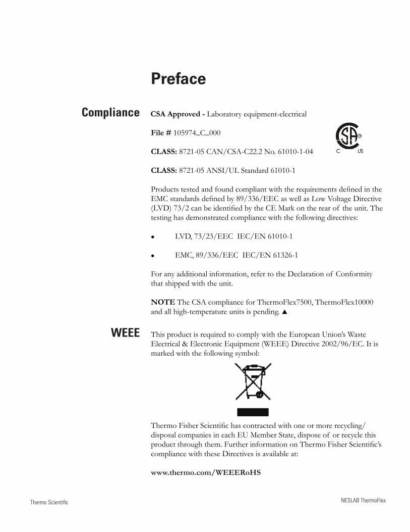
Compliance CSA Approved - Laboratory equipment-electrical
File # 105974_C_000
CLASS: 8721-05 CAN/CSA-C22.2 No. 61010-1-04
CLASS: 8721-05 ANSI/UL Standard 61010-1
Products tested and found compliant with the requirements defined in the EMC standards defined by 89/336/EEC as well as Low Voltage Directive (LVD) 73/2 can be identified by the CE Mark on the rear of the unit. The testing has demonstrated compliance with the following directives:
LVD, 73/23/EEC IEC/EN 61010-1
EMC, 89/336/EEC IEC/EN 61326-1
For any additional information, refer to the Declaration of Conformity that shipped with the unit.
NOTE The CSA compliance for ThermoFlex7500, ThermoFlex10000 and all high-temperature units is pending.
WEEE This product is required to comply with the European Union’s Waste Electrical & Electronic Equipment (WEEE) Directive 2002/96/EC. It is marked with the following symbol:
Thermo Fisher Scientific has contracted with one or more recycling/disposal companies in each EU Member State, dispose of or recycle this product through them. Further information on Thermo Fisher Scientific’s compliance with these Directives is available at:
www.thermo.com/WEEERoHS
ii NESLAB ThermoFlex
Preface
Thermo Scientific
After-sale Support Thermo Fisher Scientific is committed to customer service both during and after the sale. If you have questions concerning the unit operation, or questions concerning spare parts or Service Contracts, call our Sales, Service and Customer Support phone number, see this manual's inside cover for contact information.
When calling, please refer to the labels on the inside cover. These labels list all the necessary information needed to properly identify your unit.
Feedback We appreciate any feedback you can give us on this manual. Please e-mail us at [email protected]. Be sure to include the manual part number and the revision date listed on the front cover.
Warranty Thermo Scientific NESLAB ThermoFlex units have a warranty against defective parts and workmanship for 24 months from date of shipment. See back page for more details.
Unpacking Retain all cartons and packing material until the unit is operated and found to be in good condition. If the unit shows external or internal damage contact the transportation company and file a damage claim. Under ICC regulations, this is your responsibility.
Out of Box Failure An Out of Box Failure is defined as any product that fails to operate in conformance with sellers published specifications at initial power up. Install the unit in accordance with manufacturer's recommended operating conditions within 30 days of shipment from the seller.
Any Temperature Control product meeting the definition of an Out of Box Failure must be packed and shipped back in the original packaging to Thermo Fisher Scientific for replacement with a new unit; seller to pay the cost of shipping. Customer must receive a Return Material Authorization (RMA) from Thermo Fisher prior to shipping the unit.
Thermo Scientific NESLAB ThermoFlex 1-1
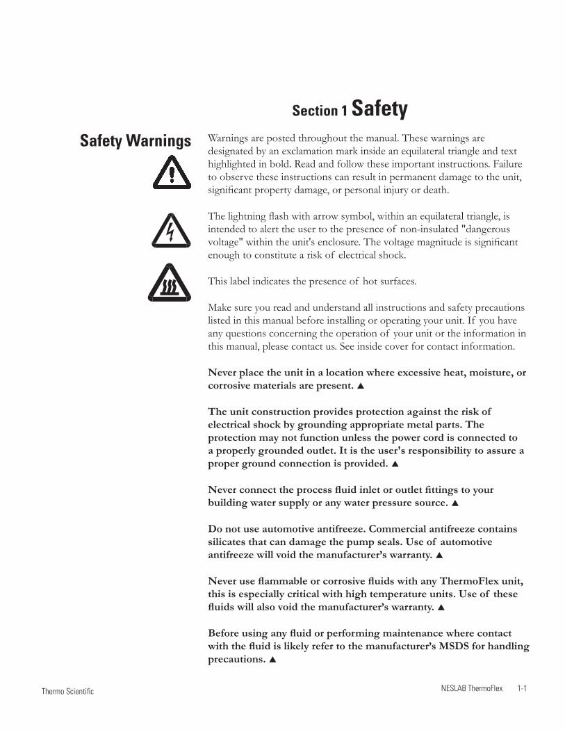
Warnings are posted throughout the manual. These warnings are designated by an exclamation mark inside an equilateral triangle and text highlighted in bold. Read and follow these important instructions. Failure to observe these instructions can result in permanent damage to the unit, significant property damage, or personal injury or death.
The lightning flash with arrow symbol, within an equilateral triangle, is intended to alert the user to the presence of non-insulated "dangerous voltage" within the unit's enclosure. The voltage magnitude is significant enough to constitute a risk of electrical shock.
This label indicates the presence of hot surfaces.
Make sure you read and understand all instructions and safety precautions listed in this manual before installing or operating your unit. If you have any questions concerning the operation of your unit or the information in this manual, please contact us. See inside cover for contact information.
Never place the unit in a location where excessive heat, moisture, or corrosive materials are present.
The unit construction provides protection against the risk of electrical shock by grounding appropriate metal parts. The protection may not function unless the power cord is connected to a properly grounded outlet. It is the user's responsibility to assure a proper ground connection is provided.
Never connect the process fluid inlet or outlet fittings to your building water supply or any water pressure source.
Do not use automotive antifreeze. Commercial antifreeze contains silicates that can damage the pump seals. Use of automotive antifreeze will void the manufacturer’s warranty.
Never use flammable or corrosive fluids with any ThermoFlex unit, this is especially critical with high temperature units. Use of these fluids will also void the manufacturer’s warranty.
Before using any fluid or performing maintenance where contact with the fluid is likely refer to the manufacturer’s MSDS for handling precautions.
Safety Warnings
Section 1 Safety
1-2 NESLAB ThermoFlex
Section 1
Thermo Scientific
When using a process fluid mixture of 0 - 75% ethylene glycol and water or 0 - 75% propylene glycol and water, check the fluid concentration on a regular basis. Changes in concentration can impact system performance. See Section 3.
Performance of installation, operation, or maintenance procedures other than those described in this manual may result in a hazardous situation and may void the manufacturer's warranty.
Transport the unit with care. Sudden jolts or drops can damage the unit's components.
Drain the unit before it is transported and/or stored in near or below freezing temperatures, see Draining in Section 8. Store the unit in the temperature range -25°C to 60°C (with packaging), and <80% relative humidity.
For high-temperature units, ensure the fluid is at a safe temperature (below 55°C) before handling or draining.
The circuit protector located on the rear of the unit is not intended to act as a disconnecting means.
Observe all warning labels.
Never remove warning labels.
Never operate damaged or leaking equipment.
Never operate the unit without process fluid in the reservoir.
Always turn off the unit and disconnect the power cord from the power source before performing any service or maintenance procedures, or before moving the unit.
Never operate the unit with panels removed.
Never operate equipment with damaged power cords.
Refer service and repairs to a qualified technician.
NESLAB ThermoFlex 2-1 Thermo Scientific
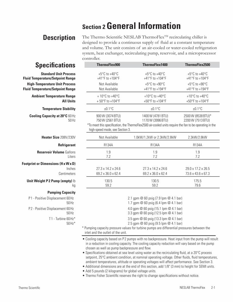
• Cooling capacity based on P 2 pumps with no backpressure. Heat input from the pump will result in a reduction in cooling capacity. The cooling capacity reduction will vary based on the pump chosen as well as pump backpressure and flow.
• Specifications obtained at sea level using water as the recirculating fluid, at a 20°C process setpoint, 25°C ambient condition, at nominal operating voltage. Other fluids, fluid temperatures, ambient temperatures, altitude or operating voltages will affect performance. See Section 3.
• Additional dimensions are at the end of this section, add 1/8" (3 mm) to height for SEMI units. • Add 5 pounds (2 kilograms) for global voltage units. • Thermo Fisher Scientific reserves the right to change specifications without notice.
Section 2 General InformationThe Thermo Scientific NESLAB ThermoFlexTM recirculating chiller is designed to provide a continuous supply of fluid at a constant temperature and volume. The unit consists of an air-cooled or water-cooled refrigeration system, heat exchanger, recirculating pump, reservoir, and a microprocessor controller.
Description
Specifications ThermoFlex900 ThermoFlex1400 ThermoFlex2500
Standard Unit Process +5°C to +40°C +5°C to +40°C +5°C to +40°C Fluid Temperature/Setpoint Range +41°F to +104°F +41°F to +104°F +41°F to +104°F
High-Temperature Unit Process Not Available +5°C to +90°C +5°C to +90°C Fluid Temperature/Setpoint Range Not Available +41°F to +194°F +41°F to +194°F
Ambient Temperature Range + 10°C to +40°C +10°C to +40°C +10°C to +40°C All Units + 50°F to +104°F +50°F to +104°F +50°F to +104°F
Temperature Stability ±0.1°C ±0.1°C ±0.1°C
Cooling Capacity at 20°C 60 Hz 900 W (3074 BTU) 1400 W (4781 BTU) 2500 W (8538 BTU)* 50 Hz 750 W (2561 BTU) 1170 W (3996 BTU) 2200 W (7513 BTU)*
Heater Size 208V/230V Not Available 1.0kW/1.2kW or 2.3kW/2.8kW 2.3kW/2.8kW
Refrigerant R134A R134A R134A
Reservoir Volume Gallons 1.9 1.9 1.9 Liters 7.2 7.2 7.2
Footprint or Dimensions (H x W x D) Inches 27.3 x 14.2 x 24.6 27.3 x 14.2 x 24.6 29.0 x 17.2 x 26.5 Centimeters 69.2 x 36.0 x 62.4 69.2 x 36.0 x 62.4 73.6 x 43.6 x 67.3
Unit Weight P 2 Pump (empty) lb 130.5 130.5 175.5 kg 59.2 59.2 79.6
Pumping Capacity P 1 - Positive Displacement 60 Hz* 2.1 gpm @ 60 psig (7.9 lpm @ 4.1 bar) 50 Hz* 1.7 gpm @ 60 psig (6.4 lpm @ 4.1 bar)
P 2 - Positive Displacement 60 Hz* 4.0 gpm @ 60 psig (15.1 lpm @ 4.1 bar) 50 Hz* 3.3 gpm @ 60 psig (12.5 lpm @ 4.1 bar)
T 1 - Turbine 60 Hz* 3.5 gpm @ 60 psig (13.3 lpm @ 4.1 bar) 50 Hz* 2.5 gpm @ 60 psig (9.5 lpm @ 4.1 bar)
*To meet this specification, the ThermoFlex2500 air-cooled units require the fan to be operating in the high-speed mode, see Section 3.
* Pumping capacity pressure values for turbine pumps are differential pressures between the inlet and the outlet of the unit.
Section 2
2-2 NESLAB ThermoFlex Thermo Scientific
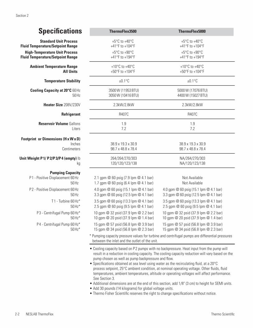
Specifications ThermoFlex3500 ThermoFlex5000 Standard Unit Process +5°C to +40°C +5°C to +40°C Fluid Temperature/Setpoint Range +41°F to +104°F +41°F to +104°F
High-Temperature Unit Process +5°C to +90°C +5°C to +90°C Fluid Temperature/Setpoint Range +41°F to +194°F +41°F to +194°F
Ambient Temperature Range +10°C to +40°C +10°C to +40°C All Units +50°F to +104°F +50°F to +104°F
Temperature Stability ±0.1°C ±0.1°C
Cooling Capacity at 20°C 60 Hz 3500 W (11953 BTU) 5000 W (17076 BTU) 50 Hz 3050 W (10416 BTU) 4400 W (15027 BTU)
Heater Size 208V/230V 2.3kW/2.8kW 2.3kW/2.8kW
Refrigerant R407C R407C
Reservoir Volume Gallons 1.9 1.9 Liters 7.2 7.2
Footprint or Dimensions (H x W x D) Inches 38.9 x 19.3 x 30.9 38.9 x 19.3 x 30.9 Centimeters 98.7 x 48.8 x 78.4 98.7 x 48.8 x 78.4
Unit Weight P 1/ P 2/P 3/P 4 (empty) lb 264/264/270/303 NA/264/270/303 kg 120/120/123/138 NA/120/123/138
Pumping Capacity P 1 - Positive Displacement 60 Hz* 2.1 gpm @ 60 psig (7.9 lpm @ 4.1 bar) Not Available 50 Hz* 1.7 gpm @ 60 psig (6.4 lpm @ 4.1 bar) Not Available
P 2 - Positive Displacement 60 Hz* 4.0 gpm @ 60 psig (15.1 lpm @ 4.1 bar) 4.0 gpm @ 60 psig (15.1 lpm @ 4.1 bar) 50 Hz* 3.3 gpm @ 60 psig (12.5 lpm @ 4.1 bar) 3.3 gpm @ 60 psig (12.5 lpm @ 4.1 bar)
T 1 - Turbine 60 Hz* 3.5 gpm @ 60 psig (13.3 lpm @ 4.1 bar) 3.5 gpm @ 60 psig (13.3 lpm @ 4.1 bar) 50 Hz* 2.5 gpm @ 60 psig (9.5 lpm @ 4.1 bar) 2.5 gpm @ 60 psig (9.5 lpm @ 4.1 bar)
P 3 - Centrifugal Pump 60 Hz* 10 gpm @ 32 psid (37.9 lpm @ 2.2 bar) 10 gpm @ 32 psid (37.9 lpm @ 2.2 bar) 50 Hz* 10 gpm @ 20 psid (37.9 lpm @ 1.4 bar) 10 gpm @ 20 psid (37.9 lpm @ 1.4 bar)
P 4 - Centrifugal Pump 60 Hz* 15 gpm @ 57 psid (56.8 lpm @ 3.9 bar) 15 gpm @ 57 psid (56.8 lpm @ 3.9 bar) 50 Hz* 15 gpm @ 34 psid (56.8 lpm @ 2.3 bar) 15 gpm @ 34 psid (56.8 lpm @ 2.3 bar)
* Pumping capacity pressure values for turbine and centrifugal pumps are differential pressures between the inlet and the outlet of the unit.
• Cooling capacity based on P 2 pumps with no backpressure. Heat input from the pump will result in a reduction in cooling capacity. The cooling capacity reduction will vary based on the pump chosen as well as pump backpressure and flow.
• Specifications obtained at sea level using water as the recirculating fluid, at a 20°C process setpoint, 25°C ambient condition, at nominal operating voltage. Other fluids, fluid temperatures, ambient temperatures, altitude or operating voltages will affect performance. See Section 3.
• Additional dimensions are at the end of this section, add 1/8" (3 cm) to height for SEMI units. • Add 30 pounds (14 kilograms) for global voltage units. • Thermo Fisher Scientific reserves the right to change specifications without notice.
Section 2
NESLAB ThermoFlex 2-3 Thermo Scientific
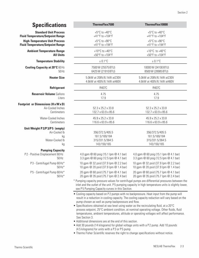
Specifications ThermoFlex7500 ThermoFlex10000 Standard Unit Process +5°C to +40°C +5°C to +40°C Fluid Temperature/Setpoint Range +41°F to +104°F +41°F to +104°F
High-Temperature Unit Process +5°C to +90°C +5°C to +90°C Fluid Temperature/Setpoint Range +41°F to +194°F +41°F to +194°F
Ambient Temperature Range +10°C to +40°C +10°C to +40°C All Units +50°F to +104°F +50°F to +104°F
Temperature Stability ± 0.1°C ± 0.1°C
Cooling Capacity at 20°C 60 Hz 7500 W (25575 BTU) 10000 W (34100 BTU) 50 Hz 6425 W (21910 BTU) 8500 W (28985 BTU)
Heater Size 5.0kW at 208V/6.1kW at230V 5.0kW at 208V/6.1kW at230V 4.6kW at 400V/6.1kW at460V 4.6kW at 400V/6.1kW at460V
Refrigerant R407C R407C
Reservoir Volume Gallons 4.75 4.75 Liters 17.9 17.9
Footprint or Dimensions (H x W x D) Air-Cooled Inches 52.3 x 25.2 x 33.8 52.3 x 25.2 x 33.8 Centimeters 132.7 x 63.9 x 85.6 132.7 x 63.9 x 85.6
Water-Cooled Inches 45.9 x 25.2 x 33.8 45.9 x 25.2 x 33.8 Centimeters 116.6 x 63.9 x 85.6 116.6 x 63.9 x 85.6
Unit Weight P 2/P 3/P 5 (empty) Air-Cooled lb 356/372.5/405.5 356/372.5/405.5 kg 161.5/169/184 161.5/169/184 Water-Cooled lb 315/331.5/364.5 315/331.5/364.5 kg 143/150/165 143/150/165
Pumping Capacity P 2 - Positive Displacement 60 Hz* 4.0 gpm @ 60 psig (15.1 lpm @ 4.1 bar) 4.0 gpm @ 60 psig (15.1 lpm @ 4.1 bar) 50 Hz* 3.3 gpm @ 60 psig (12.5 lpm @ 4.1 bar) 3.3 gpm @ 60 psig (12.5 lpm @ 4.1 bar)
P 3 - Centrifugal Pump 60 Hz* 10 gpm @ 32 psid (37.9 lpm @ 2.2 bar) 10 gpm @ 32 psid (37.9 lpm @ 2.2 bar) 50 Hz* 10 gpm @ 20 psid (37.9 lpm @ 1.4 bar) 10 gpm @ 20 psid (37.9 lpm @ 1.4 bar)
P 5 - Centrifugal Pump 60 Hz* 20 gpm @ 60 psid (75.7 lpm @ 4.1 bar) 20 gpm @ 60 psid (75.7 lpm @ 4.1 bar) 50 Hz* 20 gpm @ 35 psid (75.7 lpm @ 2.4 bar) 20 gpm @ 35 psid (75.7 lpm @ 2.4 bar)
• Cooling capacity based on P 2 pumps with no backpressure. Heat input from the pump will result in a reduction in cooling capacity. The cooling capacity reduction will vary based on the pump chosen as well as pump backpressure and flow.
• Specifications obtained at sea level using water as the recirculating fluid, at a 20°C process setpoint, 25°C ambient condition, at nominal operating voltage. Other fluids, fluid temperatures, ambient temperatures, altitude or operating voltages will affect performance. See Section 3.
• Additional dimensions are at the end of this section. • Add 30 pounds (14 kilograms) for global voltage units with a P 2 pump. Add 10 pounds
(4.5 kilograms) for units with a P 3 or P 5 pump.• Thermo Fisher Scientific reserves the right to change specifications without notice.
* Pumping capacity pressure values for centrifugal pumps are differential pressures between the inlet and the outlet of the unit. P 5 pumping capacity in high temperature units is slightly lower, see P 5 Pumping Capacity curves in this Section.
Section 2
2-4 NESLAB ThermoFlex Thermo Scientific
Temperature Setpoint
BTU/Hr Watts
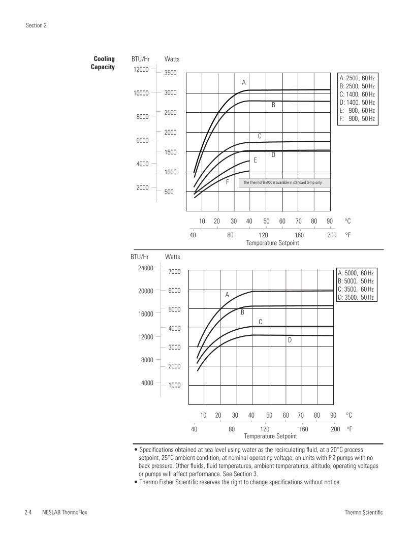
A: 5000, 60 HzB: 5000, 50 HzC: 3500, 60 HzD: 3500, 50 HzA
BC
D
7000
6000
5000
4000
3000
2000
1000
24000
20000
16000
12000
8000
4000
Cooling Capacity
A: 2500, 60 HzB: 2500, 50 HzC: 1400, 60 HzD: 1400, 50 HzE: 900, 60 HzF: 900, 50 Hz
A
C
DE
F
B
10 20 30 40 50 60 70 80 90 °C
40 80 120 160 200 °F
10 20 30 40 50 60 70 80 90 °C
40 80 120 160 200 °F
Temperature Setpoint
3500
3000
2500
2000
1500
1000
500
BTU/Hr Watts
12000
10000
8000
6000
4000
2000
• Specifications obtained at sea level using water as the recirculating fluid, at a 20°C process setpoint, 25°C ambient condition, at nominal operating voltage, on units with P 2 pumps with no back pressure. Other fluids, fluid temperatures, ambient temperatures, altitude, operating voltages or pumps will affect performance. See Section 3.
• Thermo Fisher Scientific reserves the right to change specifications without notice.
The ThermoFlex900 is available in standard temp only.
Section 2
NESLAB ThermoFlex 2-5 Thermo Scientific
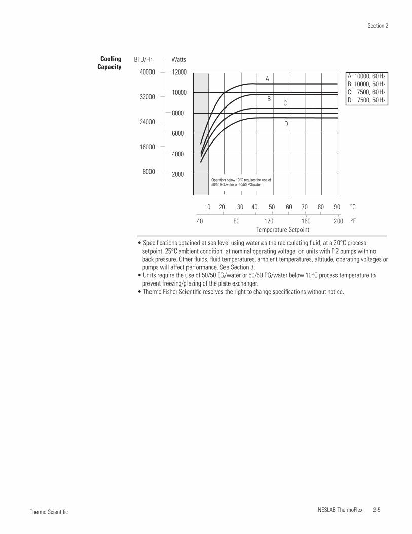
Cooling Capacity
A: 10000, 60 HzB: 10000, 50 HzC: 7500, 60 HzD: 7500, 50 Hz
A
BC
D
Temperature Setpoint
12000
10000
8000
6000
4000
2000
BTU/Hr Watts
40000
32000
24000
16000
8000
10 20 30 40 50 60 70 80 90 °C
40 80 120 160 200 °F
• Specifications obtained at sea level using water as the recirculating fluid, at a 20°C process setpoint, 25°C ambient condition, at nominal operating voltage, on units with P 2 pumps with no back pressure. Other fluids, fluid temperatures, ambient temperatures, altitude, operating voltages or pumps will affect performance. See Section 3.
• Units require the use of 50/50 EG/water or 50/50 PG/water below 10°C process temperature to prevent freezing/glazing of the plate exchanger.
• Thermo Fisher Scientific reserves the right to change specifications without notice.
Operation below 10°C requires the use of50/50 EG/water or 50/50 PG/water
Section 2
2-6 NESLAB ThermoFlex Thermo Scientific
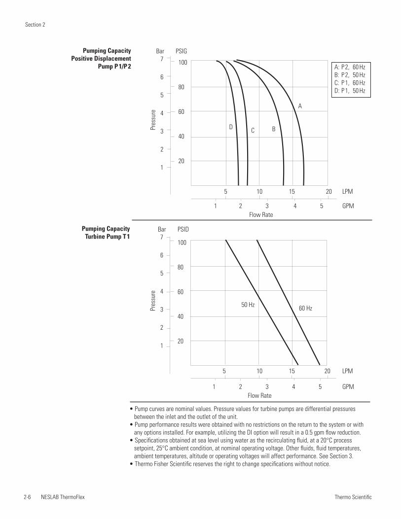
Pumping Capacity Positive Displacement
Pump P 1/P 2
Pumping Capacity Turbine Pump T 1
5 10 15 20 LPM
1 2 3 4 5 GPM
A
BCD
100
80
60
40
20
7
6
5
4
3
2
1
Bar PSIG
Pres
sure
Flow Rate
• Pump curves are nominal values. Pressure values for turbine pumps are differential pressures between the inlet and the outlet of the unit.
• Pump performance results were obtained with no restrictions on the return to the system or with any options installed. For example, utilizing the DI option will result in a 0.5 gpm flow reduction.
• Specifications obtained at sea level using water as the recirculating fluid, at a 20°C process setpoint, 25°C ambient condition, at nominal operating voltage. Other fluids, fluid temperatures, ambient temperatures, altitude or operating voltages will affect performance. See Section 3.
• Thermo Fisher Scientific reserves the right to change specifications without notice.
A: P 2, 60 HzB: P 2, 50 HzC: P 1, 60 HzD: P 1, 50 Hz
5 10 15 20 LPM
1 2 3 4 5 GPM
60 Hz50 Hz
100
80
60
40
20
7
6
5
4
3
2
1
Bar PSID
Pres
sure
Flow Rate
Section 2
NESLAB ThermoFlex 2-7 Thermo Scientific
Pres
sure
100
80
60
40
20
7
6
5
4
3
2
1
20 40 60 80 100 LPM
5 10 15 20 25 GPMFlow Rate
Bar PSID
A
B
CD
A: P 4, 60 HzB: P 4, 50 HzC: P 3, 60 HzD: P 3, 50 Hz
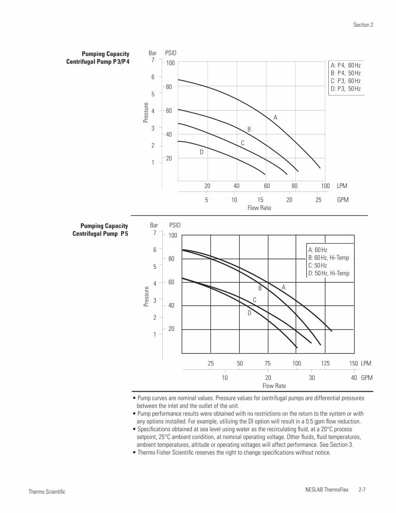
Pumping Capacity Centrifugal Pump P 3/P 4
• Pump curves are nominal values. Pressure values for centrifugal pumps are differential pressures between the inlet and the outlet of the unit.
• Pump performance results were obtained with no restrictions on the return to the system or with any options installed. For example, utilizing the DI option will result in a 0.5 gpm flow reduction.
• Specifications obtained at sea level using water as the recirculating fluid, at a 20°C process setpoint, 25°C ambient condition, at nominal operating voltage. Other fluids, fluid temperatures, ambient temperatures, altitude or operating voltages will affect performance. See Section 3.
• Thermo Fisher Scientific reserves the right to change specifications without notice.
Pumping Capacity Centrifugal Pump P 5
25 50 75 100 125 150 LPM
10 20 30 40 GPM
AB
C
D
100
80
60
40
20
7
6
5
4
3
2
1
Bar PSID
Pres
sure
Flow Rate
A: 60 HzB: 60 Hz, Hi-TempC: 50 HzD: 50 Hz, Hi-Temp
Section 2
2-8 NESLAB ThermoFlex Thermo Scientific
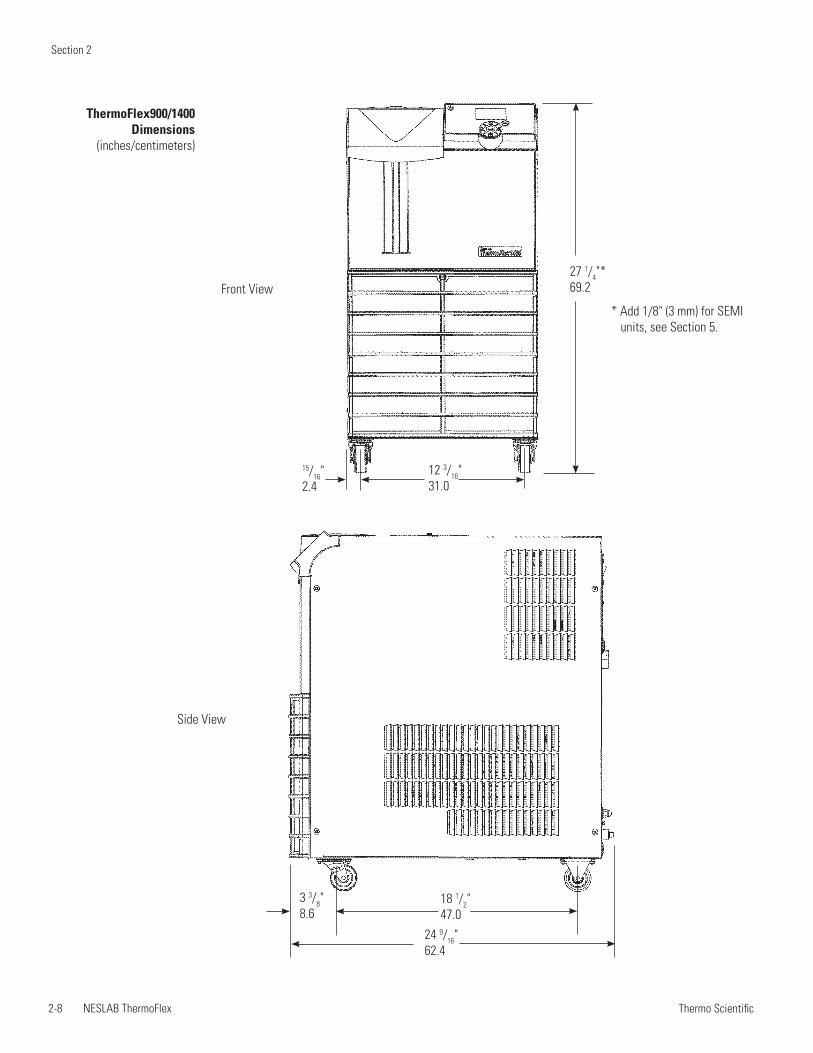
ThermoFlex900/1400 Dimensions
(inches/centimeters)
Front View27 1/4"* 69.2
12 3/16"31.0
15/16"2.4
Side View
3 3/8"8.6
18 1/2"47.0
24 9/16"62.4
* Add 1/8" (3 mm) for SEMI units, see Section 5.
Section 2
NESLAB ThermoFlex 2-9 Thermo Scientific
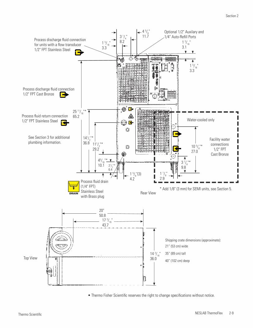
• Thermo Fisher Scientific reserves the right to change specifications without notice.
Top View
Shipping crate dimensions (approximate):
21” (53 cm) wide
35” (89 cm) tall
40” (102 cm) deep
17 3/16"43.7
14 3/16"36.0
20"50.8
Rear View
Water-cooled onlyProcess fluid return connection1/2" FPT Stainless Steel
Process discharge fluid connectionfor units with a flow transducer 1/2" FPT Stainless Steel
Process discharge fluid connection1/2" FPT Cast Bronze
Facility water connections
1/2" FPTCast Bronze
1 5/16"3.3
1 5/8"(3)4.2
3 7/8"*9.8
10 5/8"*27.0
1 1/8"2.9
45/16"*10.1
111/2"*29.2
141/2"*36.8
25 11/16"*65.2
21/2"*6.4
See Section 3 for additional plumbing information.
* Add 1/8" (3 mm) for SEMI units, see Section 5.
Process fluid drain(1/4" FPT)Stainless Steelwith Brass plug
DRAIN
4 5/8"11.7
1 3/16"3.1
1 5/16"3.3
3 1/4"8.2
Optional 1/2" Auxilary and 1/4" Auto-Refill Ports
Section 2
2-10 NESLAB ThermoFlex Thermo Scientific
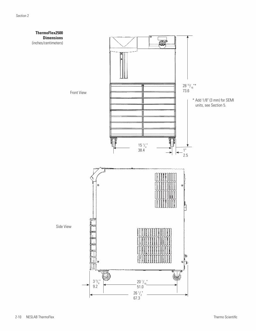
ThermoFlex2500 Dimensions
(inches/centimeters)
Front View
28 15/16"* 73.6
15 1/4"38.4 1"
2.5
Side View
3 5/8"9.2
20 1/16"51.0
26 1/2"67.3
* Add 1/8" (3 mm) for SEMI units, see Section 5.
Section 2
NESLAB ThermoFlex 2-11 Thermo Scientific
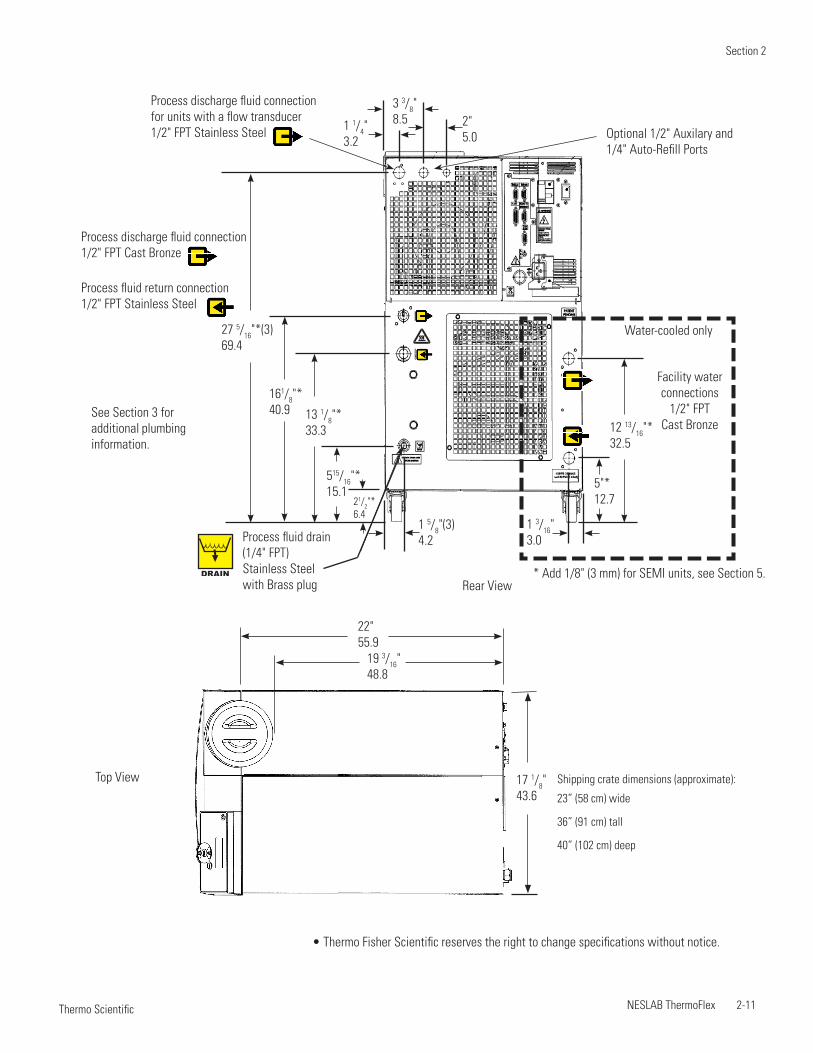
• Thermo Fisher Scientific reserves the right to change specifications without notice.
3 3/8"8.5
Rear View
Water-cooled only
Facility water connections
1/2" FPTCast Bronze
1 1/4"3.2
2"5.0
1 5/8"(3)4.2
5"*12.7
12 13/16"*32.5
1 3/16"3.0
515/16"*15.1
161/8"*40.9 13 1/8"*
33.3
27 5/16"*(3)69.4
21/2"*6.4
See Section 3 for additional plumbing information.
* Add 1/8" (3 mm) for SEMI units, see Section 5.
Process discharge fluid connectionfor units with a flow transducer 1/2" FPT Stainless Steel
DRAIN
Process fluid drain(1/4" FPT)Stainless Steelwith Brass plug
Process discharge fluid connection1/2" FPT Cast Bronze
Process fluid return connection1/2" FPT Stainless Steel
Optional 1/2" Auxilary and 1/4" Auto-Refill Ports
Shipping crate dimensions (approximate):
23” (58 cm) wide
36” (91 cm) tall
40” (102 cm) deep
Top View
19 3/16"48.8
17 1/8"43.6
22"55.9
Section 2
2-12 NESLAB ThermoFlex Thermo Scientific
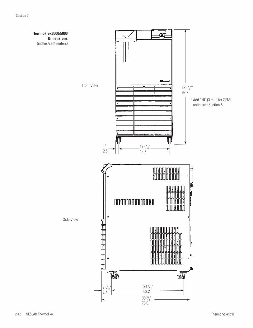
ThermoFlex3500/5000 Dimensions
(inches/centimeters)
Side View
24 1/2"62.2
3 7/16"8.7
30 3/4"78.0
38 7/8"*98.7
1"2.5
17 3/16"43.7
Front View
* Add 1/8" (3 mm) for SEMI units, see Section 5.
Section 2
NESLAB ThermoFlex 2-13 Thermo Scientific
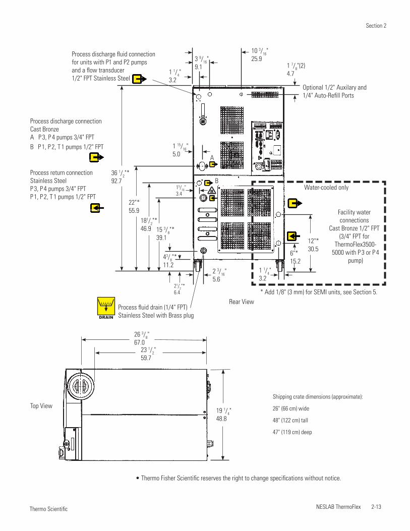
• Thermo Fisher Scientific reserves the right to change specifications without notice.
Shipping crate dimensions (approximate):
26" (66 cm) wide
48" (122 cm) tall
47" (119 cm) deep
Top View
23 1/2"59.7
19 1/4"48.8
26 3/8"67.0
Rear View
Water-cooled only
Process discharge connectionCast BronzeA P 3, P 4 pumps 3/4" FPTB P 1, P 2, T 1 pumps 1/2" FPT
Process return connectionStainless SteelP 3, P 4 pumps 3/4" FPTP 1, P 2, T 1 pumps 1/2" FPT
Facility water connections
Cast Bronze 1/2" FPT(3/4" FPT for
ThermoFlex3500-5000 with P 3 or P 4
pump)
1 15/16"5.0
1 1/4"3.2
1 7/8"(2)4.7
1 1/4"3.2
6"*15.2
12"*30.5
2 3/16"5.6
15/16"3.4
43/8"*11.2
15 3/8"*39.1
181/2"*46.9
22"*55.9
36 1/2"*92.7
21/2"*6.4 * Add 1/8" (3 mm) for SEMI units, see Section 5.
B
A
DRAIN
Process fluid drain (1/4" FPT)Stainless Steel with Brass plug
Process discharge fluid connectionfor units with P1 and P2 pumps and a flow transducer 1/2" FPT Stainless Steel
Optional 1/2" Auxilary and 1/4" Auto-Refill Ports
3 9/16"9.1
10 3/16"25.9
Section 2
2-14 NESLAB ThermoFlex Thermo Scientific
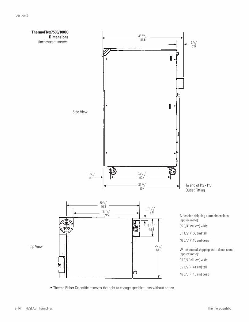
Top View
30 1/4"76.8
27 3/8"69.5
7 11/16"19.6
1 1/16"2.6
25 1/8"63.9
• Thermo Fisher Scientific reserves the right to change specifications without notice.
ThermoFlex7500/10000 Dimensions
(inches/centimeters)
24 9/16"62.4
31 5/8"80.4
3 1/8"7.9
33 11/16"85.5
3 3/16"8.0
Side View
To end of P 3 - P 5 Outlet Fitting
Water-cooled shipping crate dimensions (approximate):
35 3/4” (91 cm) wide
55 1/2” (141 cm) tall
46 3/8” (118 cm) deep
Air-cooled shipping crate dimensions (approximate):
35 3/4” (91 cm) wide
61 1/2” (156 cm) tall
46 3/8” (118 cm) deep
Section 2
NESLAB ThermoFlex 2-15 Thermo Scientific
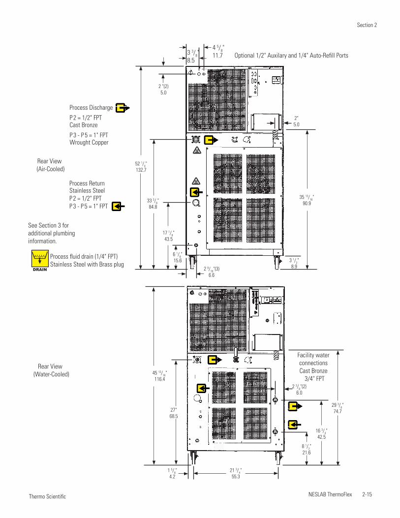
45 13/16"116.4
1 5/8"4.2
2 3/8"(2)6.0
21 3/4"55.3
29 3/8"74.7
16 3/4"42.5
8 1/2"21.6
27"68.5
Rear View (Water-Cooled)
Facility water connectionsCast Bronze
3/4" FPT
6 1/8"15.6
2 9/19"(3)6.6
17 1/8"43.5
2 "(2)5.0
33 3/8"84.8
52 1/4"132.7
35 13/16"90.9
3 1/2"8.9
2"5.0
Rear View (Air-Cooled)
Optional 1/2" Auxilary and 1/4" Auto-Refill Ports
See Section 3 for additional plumbing information.
Process Discharge
P 2 = 1/2" FPTCast Bronze
P 3 - P 5 = 1" FPTWrought Copper
Process ReturnStainless Steel P 2 = 1/2" FPTP 3 - P 5 = 1" FPT
DRAIN
Process fluid drain (1/4" FPT)Stainless Steel with Brass plug
3 3/8"8.5
4 5/8"11.7

Section 2
2-16 NESLAB ThermoFlex Thermo Scientific
NESLAB ThermoFlex 3-1 Thermo Scientific
Section 3 Installation
Ambient Temperature Range* 10°C to 40°C (50°F to 104°F)
Relative Humidity Range 10% to 80% (non-condensing)
Operating Altitude* Sea Level to 8000 feet (2438 meters)
Overvoltage Category II
Pollution Degree 2
Degree of Protection IP 20
Never place the unit in a location where excessive heat, moisture, inadequate ventilation, or corrosive materials are present.
Air-cooled units retain their full rated capacity at 20°C setpoint in ambient temperatures up to 25°C (77°F). For ambient temperatures above 25°C please de-rate the cooling capacity 3% for every 1°C above 25°C (77°F), up to a maximum ambient temperature of 40°C (104°F). Please note that when operating at a process temperature lower than 20°C the de-rate percentage may increase due to additional gains from losses to ambient.
NOTE Depending on the setpoint and ambient temperatures, there may be a heat gain or loss through the plumbing resulting in a variation from setpoint temperature at the application inlet. Applications with large temperature variations between ambient and setpoint temperatures, and/or long plumbing lengths, may require additional insulation.
ThermoFlex2500 air-cooled units are equipped with a two-speed fan. Should the unit's internal ambient temperature reach 50°C for 30 seconds, or reach 53°C, the fan speed will switch from slow speed to high speed to maintain internal temperatures within acceptable limits. When the temperature reaches 44°C or below for at least 15 minutes the speed will return to low. When in high speed the unit's decibel level increases significantly.
NOTE High speed is required for the unit to achieve its 2500 watt cooling capacity. At high-end operating conditions the fan can be set to run at high speed all the time using the controller's SETTINGS display, see Section 4.
Site Requirements
*Because of the decrease in air density, maximum temperature for the air entering an air-cooled ThermoFlex is reduced by 1°C per 1,000 feet above sea level. In addition, cooling capacity is reduced 1.2% per 1,000 feet above sea level.
Section 3
3-2 NESLAB ThermoFlex Thermo Scientific
Electrical Requirements
Units installed below the end-user application may enable system fluid to drain back into the chiller and cause spillage. Thermo Fisher offers an anti-drainback kit to prevent any spillage, see Section 5.
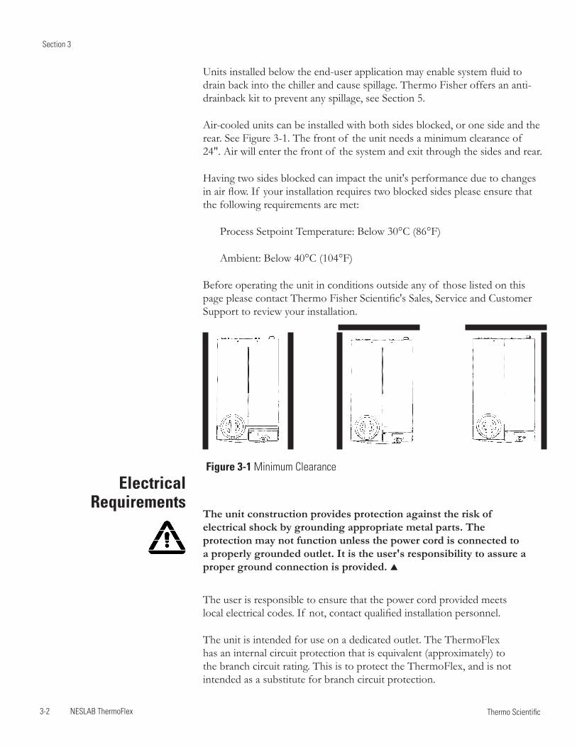
Air-cooled units can be installed with both sides blocked, or one side and the rear. See Figure 3-1. The front of the unit needs a minimum clearance of 24". Air will enter the front of the system and exit through the sides and rear.
Having two sides blocked can impact the unit's performance due to changes in air flow. If your installation requires two blocked sides please ensure that the following requirements are met:
Process Setpoint Temperature: Below 30°C (86°F)
Ambient: Below 40°C (104°F)
Before operating the unit in conditions outside any of those listed on this page please contact Thermo Fisher Scientific's Sales, Service and Customer Support to review your installation.
The unit construction provides protection against the risk of electrical shock by grounding appropriate metal parts. The protection may not function unless the power cord is connected to a properly grounded outlet. It is the user's responsibility to assure a proper ground connection is provided.
The user is responsible to ensure that the power cord provided meets local electrical codes. If not, contact qualified installation personnel.
The unit is intended for use on a dedicated outlet. The ThermoFlex has an internal circuit protection that is equivalent (approximately) to the branch circuit rating. This is to protect the ThermoFlex, and is not intended as a substitute for branch circuit protection.
Figure 3-1 Minimum Clearance
Section 3
NESLAB ThermoFlex 3-3 Thermo Scientific
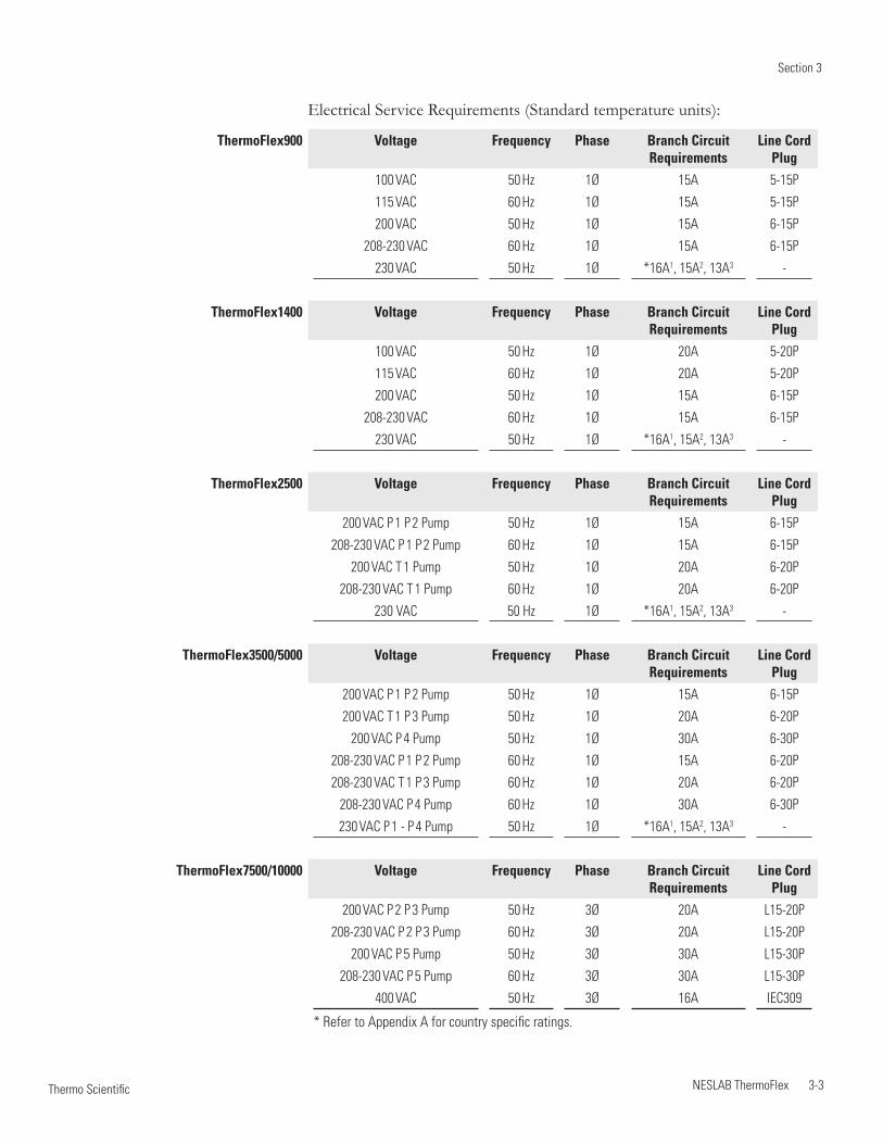
* Refer to Appendix A for country specific ratings.
Electrical Service Requirements (Standard temperature units):
ThermoFlex900 Voltage Frequency Phase Branch Circuit Requirements
Line Cord Plug
100 VAC 50 Hz 1Ø 15A 5-15P
115 VAC 60 Hz 1Ø 15A 5-15P
200 VAC 50 Hz 1Ø 15A 6-15P
208-230 VAC 60 Hz 1Ø 15A 6-15P
230 VAC 50 Hz 1Ø *16A1, 15A2, 13A3 -
ThermoFlex1400 Voltage Frequency Phase Branch Circuit Requirements
Line Cord Plug
100 VAC 50 Hz 1Ø 20A 5-20P
115 VAC 60 Hz 1Ø 20A 5-20P
200 VAC 50 Hz 1Ø 15A 6-15P
208-230 VAC 60 Hz 1Ø 15A 6-15P
230 VAC 50 Hz 1Ø *16A1, 15A2, 13A3 -
ThermoFlex2500 Voltage Frequency Phase Branch Circuit Requirements
Line Cord Plug
200 VAC P 1 P 2 Pump 50 Hz 1Ø 15A 6-15P
208-230 VAC P 1 P 2 Pump 60 Hz 1Ø 15A 6-15P
200 VAC T 1 Pump 50 Hz 1Ø 20A 6-20P
208-230 VAC T 1 Pump 60 Hz 1Ø 20A 6-20P
230 VAC 50 Hz 1Ø *16A1, 15A2, 13A3 -
ThermoFlex3500/5000 Voltage Frequency Phase Branch Circuit Requirements
Line Cord Plug
200 VAC P 1 P 2 Pump 50 Hz 1Ø 15A 6-15P
200 VAC T 1 P 3 Pump 50 Hz 1Ø 20A 6-20P
200 VAC P 4 Pump 50 Hz 1Ø 30A 6-30P
208-230 VAC P 1 P 2 Pump 60 Hz 1Ø 15A 6-20P
208-230 VAC T 1 P 3 Pump 60 Hz 1Ø 20A 6-20P
208-230 VAC P 4 Pump 60 Hz 1Ø 30A 6-30P
230 VAC P 1 - P 4 Pump 50 Hz 1Ø *16A1, 15A2, 13A3 -
ThermoFlex7500/10000 Voltage Frequency Phase Branch CircuitRequirements
Line Cord Plug
200 VAC P 2 P 3 Pump 50 Hz 3Ø 20A L15-20P
208-230 VAC P 2 P 3 Pump 60 Hz 3Ø 20A L15-20P
200 VAC P 5 Pump 50 Hz 3Ø 30A L15-30P
208-230 VAC P 5 Pump 60 Hz 3Ø 30A L15-30P
400 VAC 50 Hz 3Ø 16A IEC309
Section 3
3-4 NESLAB ThermoFlex Thermo Scientific
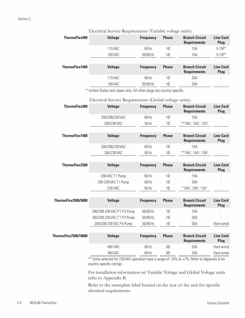
** Units selected for 230 VAC operation have a range of -10% to +7%. Refer to Appendix A for country specific ratings.
For installation information on Variable Voltage and Global Voltage units refer to Appendix B.Refer to the nameplate label located on the rear of the unit for specific electrical requirements.
* United States and Japan only. All other plugs are country specific.
ThermoFlex900 Voltage Frequency Phase Branch Circuit Requirements
Line Cord Plug
200/208/230 VAC 60 Hz 1Ø 15A -
200/230 VAC 50 Hz 1Ø **16A1, 15A2, 13A3 -
ThermoFlex1400 Voltage Frequency Phase Branch Circuit Requirements
Line Cord Plug
200/208/230 VAC 60 Hz 1Ø 15A -
200/230 VAC 50 Hz 1Ø **16A1, 15A2, 13A3 -
ThermoFlex2500 Voltage Frequency Phase Branch Circuit Requirements
Line Cord Plug
200 VAC T 1 Pump 60 Hz 1Ø 15A -
208-230 VAC T 1 Pump 60 Hz 1Ø 20A -
230 VAC 50 Hz 1Ø *16A1, 15A2, 13A3 -
ThermoFlex3500/5000 Voltage Frequency Phase Branch Circuit Requirements
Line Cord Plug
200/208-230 VAC P 1 P 3 Pump 50/60 Hz 1Ø 15A -
200/208-230 VAC T 1 P 3 Pump 50/60 Hz 1Ø 20A -
200/208-230 VAC P 4 Pump 50/60 Hz 1Ø 30A Hard wired
ThermoFlex7500/10000 Voltage Frequency Phase Branch CircuitRequirements
Line Cord Plug
400 VAC 60 Hz 3Ø 20A Hard wired
460 VAC 60 Hz 3Ø 20A Hard wired
ThermoFlex900 Voltage Frequency Phase Branch Circuit Requirements
Line Cord Plug
115 VAC 60 Hz 1Ø 15A 5-15P*
100 VAC 50/60 Hz 1Ø 15A 5-15P*
ThermoFlex1400 Voltage Frequency Phase Branch Circuit Requirements
Line Cord Plug
115 VAC 60 Hz 1Ø 20A -
100 VAC 50/60 Hz 1Ø 20A -
Electrical Service Requirements (Variable voltage units):
Electrical Service Requirements (Global voltage units):
Section 3
NESLAB ThermoFlex 3-5 Thermo Scientific
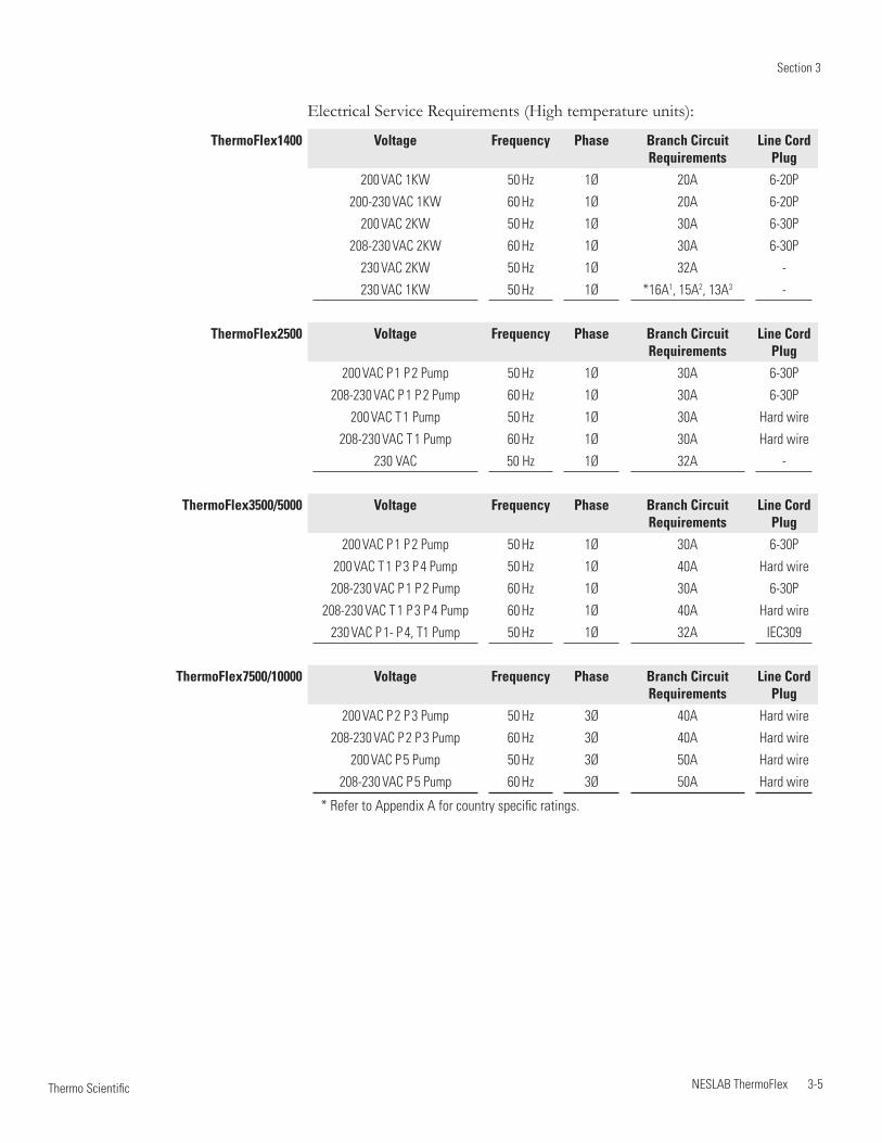
* Refer to Appendix A for country specific ratings.
Electrical Service Requirements (High temperature units):
ThermoFlex1400 Voltage Frequency Phase Branch Circuit Requirements
Line Cord Plug
200 VAC 1KW 50 Hz 1Ø 20A 6-20P
200-230 VAC 1KW 60 Hz 1Ø 20A 6-20P
200 VAC 2KW 50 Hz 1Ø 30A 6-30P
208-230 VAC 2KW 60 Hz 1Ø 30A 6-30P
230 VAC 2KW 50 Hz 1Ø 32A -
230 VAC 1KW 50 Hz 1Ø *16A1, 15A2, 13A3 -
ThermoFlex2500 Voltage Frequency Phase Branch Circuit Requirements
Line Cord Plug
200 VAC P 1 P 2 Pump 50 Hz 1Ø 30A 6-30P
208-230 VAC P 1 P 2 Pump 60 Hz 1Ø 30A 6-30P
200 VAC T 1 Pump 50 Hz 1Ø 30A Hard wire
208-230 VAC T 1 Pump 60 Hz 1Ø 30A Hard wire
230 VAC 50 Hz 1Ø 32A -
ThermoFlex3500/5000 Voltage Frequency Phase Branch Circuit Requirements
Line Cord Plug
200 VAC P 1 P 2 Pump 50 Hz 1Ø 30A 6-30P
200 VAC T 1 P 3 P 4 Pump 50 Hz 1Ø 40A Hard wire
208-230 VAC P 1 P 2 Pump 60 Hz 1Ø 30A 6-30P
208-230 VAC T 1 P 3 P 4 Pump 60 Hz 1Ø 40A Hard wire
230 VAC P 1- P 4, T1 Pump 50 Hz 1Ø 32A IEC309
ThermoFlex7500/10000 Voltage Frequency Phase Branch CircuitRequirements
Line Cord Plug
200 VAC P 2 P 3 Pump 50 Hz 3Ø 40A Hard wire
208-230 VAC P 2 P 3 Pump 60 Hz 3Ø 40A Hard wire
200 VAC P 5 Pump 50 Hz 3Ø 50A Hard wire
208-230 VAC P 5 Pump 60 Hz 3Ø 50A Hard wire
Section 3
3-6 NESLAB ThermoFlex Thermo Scientific
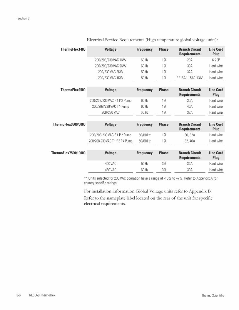
** Units selected for 230 VAC operation have a range of -10% to +7%. Refer to Appendix A for country specific ratings.
For installation information Global Voltage units refer to Appendix B.Refer to the nameplate label located on the rear of the unit for specific electrical requirements.
ThermoFlex1400 Voltage Frequency Phase Branch Circuit Requirements
Line Cord Plug
200/208/230 VAC 1KW 60 Hz 1Ø 20A 6-20P
200/208/230 VAC 2KW 60 Hz 1Ø 30A Hard wire
200/230 VAC 2KW 50 Hz 1Ø 32A Hard wire
200/230 VAC 1KW 50 Hz 1Ø **16A1, 15A2, 13A3 Hard wire
ThermoFlex2500 Voltage Frequency Phase Branch Circuit Requirements
Line Cord Plug
200/208/230 VAC P 1 P 2 Pump 60 Hz 1Ø 30A Hard wire
200/208/230 VAC T 1 Pump 60 Hz 1Ø 40A Hard wire
200/230 VAC 50 Hz 1Ø 32A Hard wire
ThermoFlex3500/5000 Voltage Frequency Phase Branch Circuit Requirements
Line Cord Plug
200/208-230 VAC P 1 P 2 Pump 50/60 Hz 1Ø 30, 32A Hard wire
200/208-230 VAC T 1 P 3 P 4 Pump 50/60 Hz 1Ø 32, 40A Hard wire
ThermoFlex7500/10000 Voltage Frequency Phase Branch CircuitRequirements
Line Cord Plug
400 VAC 50 Hz 3Ø 32A Hard wire
460 VAC 60 Hz 3Ø 30A Hard wire
Electrical Service Requirements (High temperature global voltage units):
Section 3
NESLAB ThermoFlex 3-7 Thermo Scientific
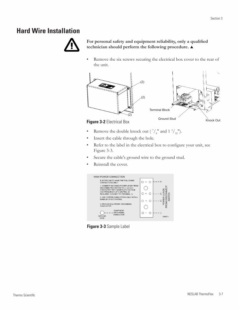
Hard Wire Installation For personal safety and equipment reliability, only a qualified technician should perform the following procedure.
Remove the six screws securing the electrical box cover to the rear of • the unit.
Remove the double knock out ( • 7/8" and 1 3/32").Insert the cable through the hole.• Refer to the label in the electrical box to configure your unit, see • Figure 3-3.Secure the cable's ground wire to the ground stud.• Reinstall the cover.•
Terminal Block
Ground Stud Knock Out
(2)
(2)
(2)
Figure 3-2 Electrical Box
Figure 3-3 Sample Label
Section 3
3-8 NESLAB ThermoFlex Thermo Scientific
Plumbing Requirements
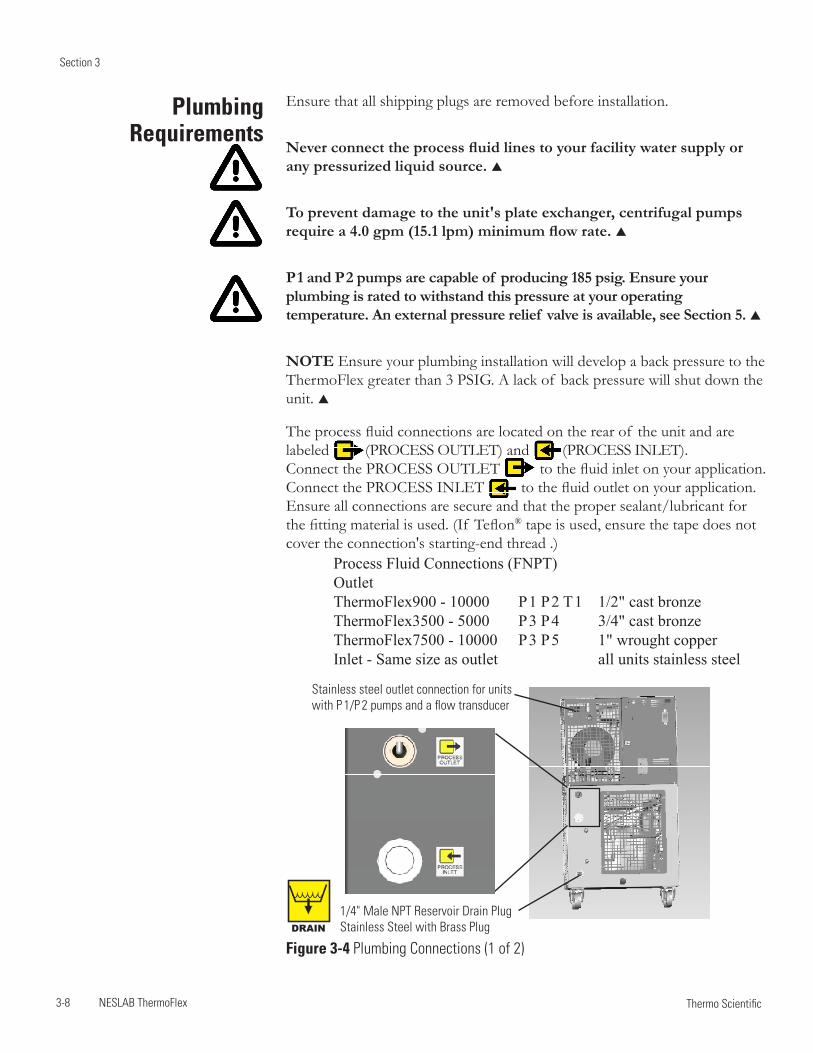
Ensure that all shipping plugs are removed before installation.
Never connect the process fluid lines to your facility water supply or any pressurized liquid source.
To prevent damage to the unit's plate exchanger, centrifugal pumps require a 4.0 gpm (15.1 lpm) minimum flow rate.
P 1 and P 2 pumps are capable of producing 185 psig. Ensure your plumbing is rated to withstand this pressure at your operating temperature. An external pressure relief valve is available, see Section 5.
NOTE Ensure your plumbing installation will develop a back pressure to the ThermoFlex greater than 3 PSIG. A lack of back pressure will shut down the unit.
The process fluid connections are located on the rear of the unit and are labeled (PRoCESS ouTlET) and (PRoCeSS InleT). Connect the PRoCESS ouTlET to the fluid inlet on your application. Connect the PRoCeSS InleT to the fluid outlet on your application. Ensure all connections are secure and that the proper sealant/lubricant for the fitting material is used. (If Teflon® tape is used, ensure the tape does not cover the connection's starting-end thread .)
1/4" Male NPT Reservoir Drain Plug Stainless Steel with Brass Plug
Stainless steel outlet connection for units with P 1/P 2 pumps and a flow transducer
Figure 3-4 Plumbing Connections (1 of 2)
Process Fluid Connections (FNPT)Outlet ThermoFlex900 - 10000 P 1 P 2 T 1 1/2" cast bronzeThermoFlex3500 - 5000 P 3 P 4 3/4" cast bronzeThermoFlex7500 - 10000 P 3 P 5 1" wrought copperInlet - Same size as outlet all units stainless steel
DRAIN
Section 3
NESLAB ThermoFlex 3-9 Thermo Scientific
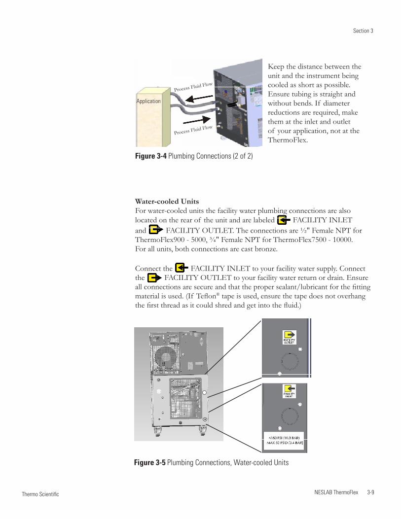
Water-cooled Units For water-cooled units the facility water plumbing connections are also located on the rear of the unit and are labeled FACIlITY InleT and FACIlITY oUTleT. The connections are ½" Female nPT for ThermoFlex900 - 5000, ¾" Female nPT for ThermoFlex7500 - 10000. For all units, both connections are cast bronze.
Connect the FACIlITY InleT to your facility water supply. Connect the FACIlITY oUTleT to your facility water return or drain. Ensure all connections are secure and that the proper sealant/lubricant for the fitting material is used. (If Teflon® tape is used, ensure the tape does not overhang the first thread as it could shred and get into the fluid.)
Figure 3-5 Plumbing Connections, Water-cooled Units
Keep the distance between the unit and the instrument being cooled as short as possible. Ensure tubing is straight and without bends. If diameter reductions are required, make them at the inlet and outlet of your application, not at the ThermoFlex.
Figure 3-4 Plumbing Connections (2 of 2)
Process Fluid Flow
Process Fluid Flow
Application
Section 3
3-10 NESLAB ThermoFlex Thermo Scientific
Process Fluid Requirements
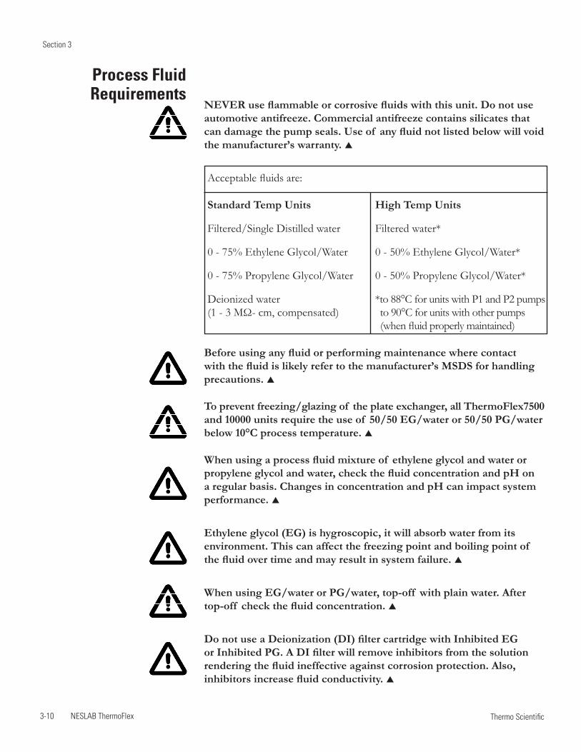
NEVER use flammable or corrosive fluids with this unit. Do not use automotive antifreeze. Commercial antifreeze contains silicates that can damage the pump seals. Use of any fluid not listed below will void the manufacturer’s warranty.
Acceptable fluids are:
Standard Temp Units High Temp Units
Filtered/Single Distilled water Filtered water*
0 - 75% Ethylene Glycol/Water 0 - 50% Ethylene Glycol/Water*
0 - 75% Propylene Glycol/Water 0 - 50% Propylene Glycol/Water*
Deionized water *to 88°C for units with P1 and P2 pumps (1 - 3 MΩ- cm, compensated) *to 90°C for units with other pumps (when fluid properly maintained)
Before using any fluid or performing maintenance where contact with the fluid is likely refer to the manufacturer’s MSDS for handling precautions.
To prevent freezing/glazing of the plate exchanger, all ThermoFlex7500 and 10000 units require the use of 50/50 EG/water or 50/50 PG/water below 10°C process temperature.
When using a process fluid mixture of ethylene glycol and water or propylene glycol and water, check the fluid concentration and pH on a regular basis. Changes in concentration and pH can impact system performance.
Ethylene glycol (EG) is hygroscopic, it will absorb water from its environment. This can affect the freezing point and boiling point of the fluid over time and may result in system failure.
When using EG/water or PG/water, top-off with plain water. After top-off check the fluid concentration.
Do not use a Deionization (DI) filter cartridge with Inhibited EG or Inhibited PG. A DI filter will remove inhibitors from the solution rendering the fluid ineffective against corrosion protection. Also, inhibitors increase fluid conductivity.
Section 3
NESLAB ThermoFlex 3-11 Thermo Scientific
Filtered/Single Distilled Water This fluid is acceptable primarily because it has all microorganisms that cause biological fouling removed through vaporizing and condensing the water. However, distilled water does not remain pure for very long when exposed to the atmosphere. Air-born spores can contaminate the water and activate algae growth. An effective maintenance plan would include switching out the fluid with newly distilled water every six months. The particulates that have been filtered out in the process are also preventive in keeping the system “clean” of contaminants.
Uninhibited Ethylene Glycol/Water Ethylene glycol is used to depress the freezing point of water as a coolant. We recommend not using the uninhibited (no corrosion additives) ethylene glycol. It is more corrosive to copper than plain water so it is not recommended unless required for the application.
Inhibited Ethylene Glycol/Water Inhibited glycol can be used to increase the operating temperature range of the fluid but not as a “pre-mixed anticorrosive” solution. Industry standards use a pH standard of 8 to determine when the fluid has become corrosive. Dowtherm® is an ethylene based product that contains dipotassium phosphates in a 4% concentration. The recommended use of Dowtherm® is mixing with distilled or deionized water or water that contains less than 25 ppm chloride and sulfate and less than 100 ppm total hardness of CACo3.
The general term, inhibited glycol/water, is too close to meaning inhibited water. Inhibited water can have many types of additives including chromate that will quickly foul the cooling system. Some inhibitor additives can release the bonding agent in the carbon graphite in P1 and P2 pumps so they are incompatible, such as Sodium Hydroxide.
Uninhibited Propylene Glycol/Water Although the use of propylene glycol is similar to ethylene glycol, propylene glycol is considered “safe” to use in the food industry.
Inhibited Propylene Glycol/Water Same issues as with uninhibited propylene and inhibited ethylene glycol.
Compatibility with Acceptable
Fluids
Section 3
3-12 NESLAB ThermoFlex Thermo Scientific
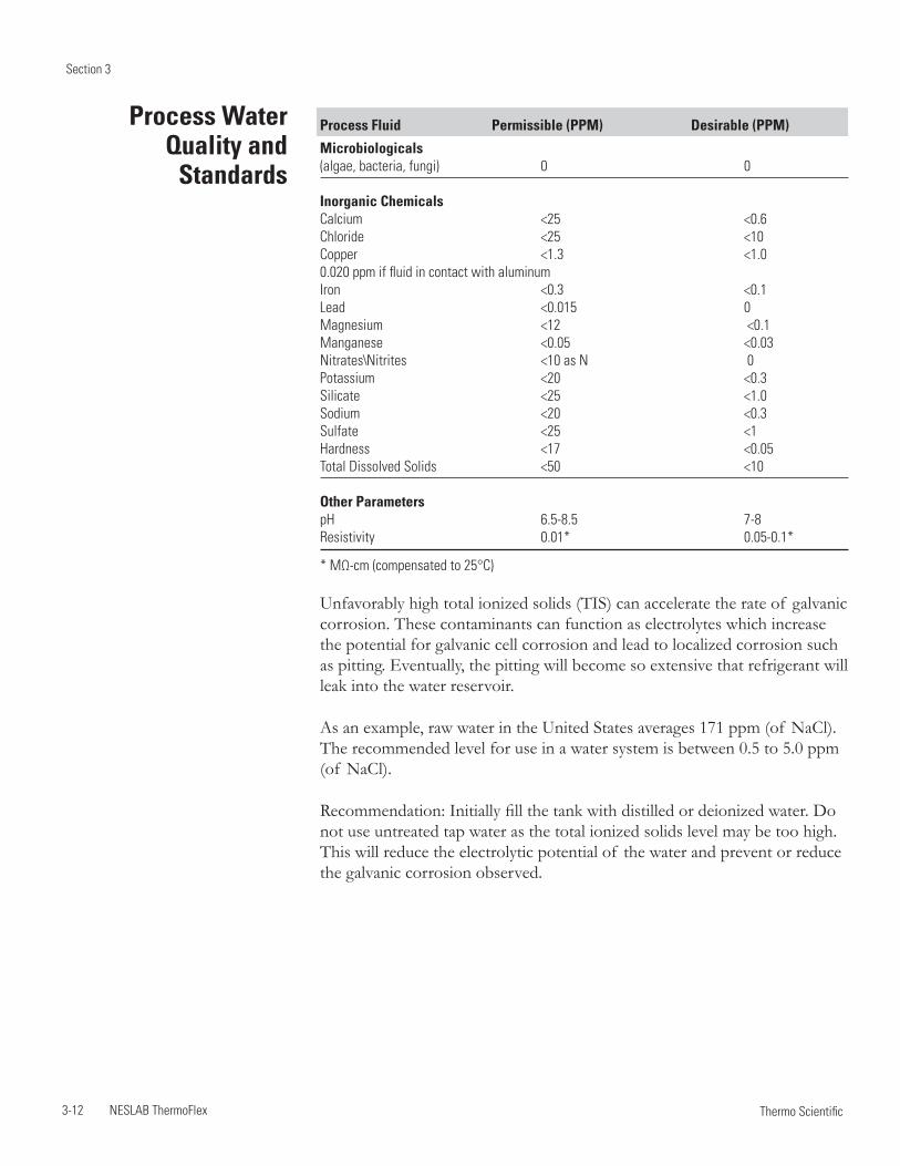
Process Fluid Permissible (PPM) Desirable (PPM)
Microbiologicals (algae, bacteria, fungi) 0 0
Inorganic ChemicalsCalcium <25 <0.6Chloride <25 <10 Copper <1.3 <1.00.020 ppm if fluid in contact with aluminumIron <0.3 <0.1Lead <0.015 0Magnesium <12 <0.1Manganese <0.05 <0.03Nitrates\Nitrites <10 as N 0Potassium <20 <0.3Silicate <25 <1.0Sodium <20 <0.3Sulfate <25 <1Hardness <17 <0.05Total Dissolved Solids <50 <10
Other ParameterspH 6.5-8.5 7-8Resistivity 0.01* 0.05-0.1*
* MΩ-cm (compensated to 25°C)
Unfavorably high total ionized solids (TIS) can accelerate the rate of galvanic corrosion. These contaminants can function as electrolytes which increase the potential for galvanic cell corrosion and lead to localized corrosion such as pitting. Eventually, the pitting will become so extensive that refrigerant will leak into the water reservoir.
As an example, raw water in the United States averages 171 ppm (of naCl). The recommended level for use in a water system is between 0.5 to 5.0 ppm (of naCl).
Recommendation: Initially fill the tank with distilled or deionized water. Do not use untreated tap water as the total ionized solids level may be too high. This will reduce the electrolytic potential of the water and prevent or reduce the galvanic corrosion observed.
Process Water Quality and
Standards
Section 3
NESLAB ThermoFlex 3-13 Thermo Scientific
Initial Filling Ensure the reservoir drain plug on the back of the unit is in place and that all plumbing connections are secure.
Before using any fluid refer to the manufacturer’s MSDS for handling precautions.
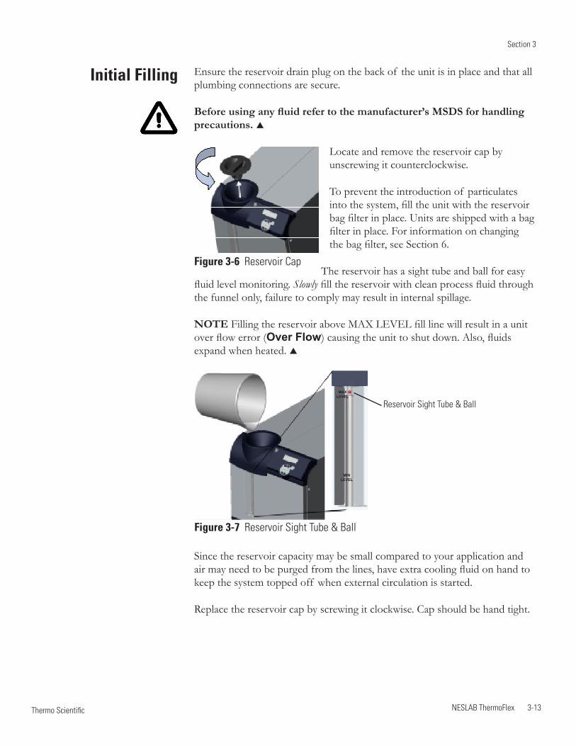
locate and remove the reservoir cap by unscrewing it counterclockwise.
To prevent the introduction of particulates into the system, fill the unit with the reservoir bag filter in place. Units are shipped with a bag filter in place. For information on changing the bag filter, see Section 6.
The reservoir has a sight tube and ball for easy fluid level monitoring. Slowly fill the reservoir with clean process fluid through the funnel only, failure to comply may result in internal spillage.
NOTE Filling the reservoir above MAX leVel fill line will result in a unit over flow error (Over Flow) causing the unit to shut down. Also, fluids expand when heated.
Figure 3-6 Reservoir Cap
Reservoir Sight Tube & BallMAX
LEVEL
MIN LEVEL
Figure 3-7 Reservoir Sight Tube & Ball
Since the reservoir capacity may be small compared to your application and air may need to be purged from the lines, have extra cooling fluid on hand to keep the system topped off when external circulation is started.
Replace the reservoir cap by screwing it clockwise. Cap should be hand tight.
Section 3
3-14 NESLAB ThermoFlex Thermo Scientific
Water Treatment Kit (North America Only)
Fluid Top Off
A Thermo Fisher Treatment Kit is available and is designed to minimize the effects of corrosion, scale, fouling, and microbial contamination. It allows the system to continue providing reliable service with optimal efficiency for the life of the unit.
The kit includes a biocide and corrosion inhibitor capable of treating up to ten gallons of application water and is designed to provide protection for a period of six months. This kit is compatible with the following fluids:
• Filtered/Single Distilled Water
• Uninhibited ethylene Glycol/Water
• Uninhibited Propylene/Water
• Deionized (DI) Water*
• Reverse osmosis (Ro) Water
*Do not use the Thermo Fisher Water Treatment Kit with a DI filtered system; the filter will remove a portion of the reagent’s active ingredients limiting its effectiveness.
Ensure the reservoir cap is at a safe handling temperature before removing.
Remove the reservoir cap by unscrewing it counterclockwise.
To prevent the introduction of particulates into the system, fill the unit with the reservoir bag filter in place. Units are shipped with a bag filter in place. For information on changing the bag filter, see Section 6.
The reservoir has a sight tube and ball for easy fluid level monitoring. Slowly fill the reservoir with clean process fluid through the funnel only, failure to comply may result in internal spillage.
NOTE Filling the reservoir above MAX leVel fill line will result in a unit over flow error (Over Flow) causing the unit to shut down. Also, fluids expand when heated.
NOTE Adding fluid that has a temperature differential with the fluid already in the reservoir will temporarily affect unit stability performance.
Section 3
NESLAB ThermoFlex 3-15 Thermo Scientific
Faci
lity
Pre
ssur
e D
rop
PS
ID
2 4 6 8 Facility Flow - GPM
Faci
lity
Tem
pera
ture
°C
45403530252015105
30
25
20
15
10
5
°C
PSID
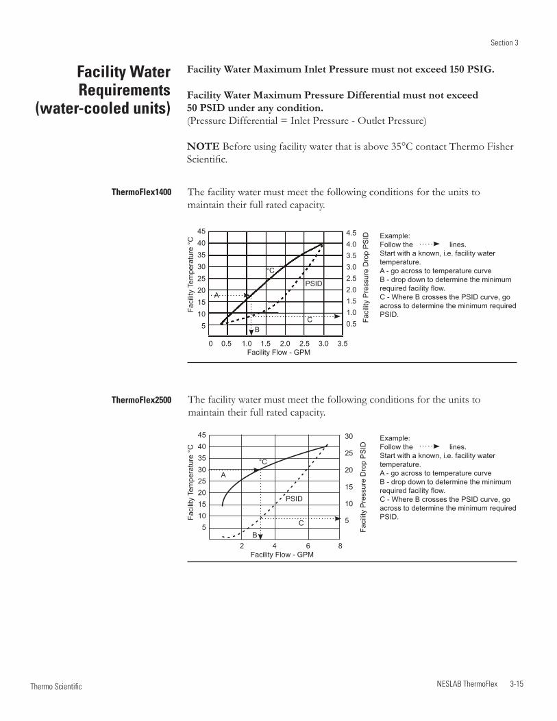
The facility water must meet the following conditions for the units to maintain their full rated capacity.
ThermoFlex2500
Facility Water Maximum Inlet Pressure must not exceed 150 PSIG.
Facility Water Maximum Pressure Differential must not exceed 50 PSID under any condition. (Pressure Differential = Inlet Pressure - outlet Pressure)
NOTE Before using facility water that is above 35°C contact Thermo Fisher Scientific.
The facility water must meet the following conditions for the units to maintain their full rated capacity.
Faci
lity
Pre
ssur
e D
rop
PS
ID
0 0.5 1.0 1.5 2.0 2.5 3.0 3.5 Facility Flow - GPM
Faci
lity
Tem
pera
ture
°C
45403530252015105
4.54.03.53.02.52.01.51.00.5
°C
PSID
Facility Water Requirements
(water-cooled units)
ThermoFlex1400
Example:Follow the lines.Start with a known, i.e. facility water temperature.A - go across to temperature curveB - drop down to determine the minimum required facility flow.C - Where B crosses the PSID curve, go across to determine the minimum required PSID.
Example:Follow the lines.Start with a known, i.e. facility water temperature.A - go across to temperature curveB - drop down to determine the minimum required facility flow.C - Where B crosses the PSID curve, go across to determine the minimum required PSID.
A
A
B
B
C
C
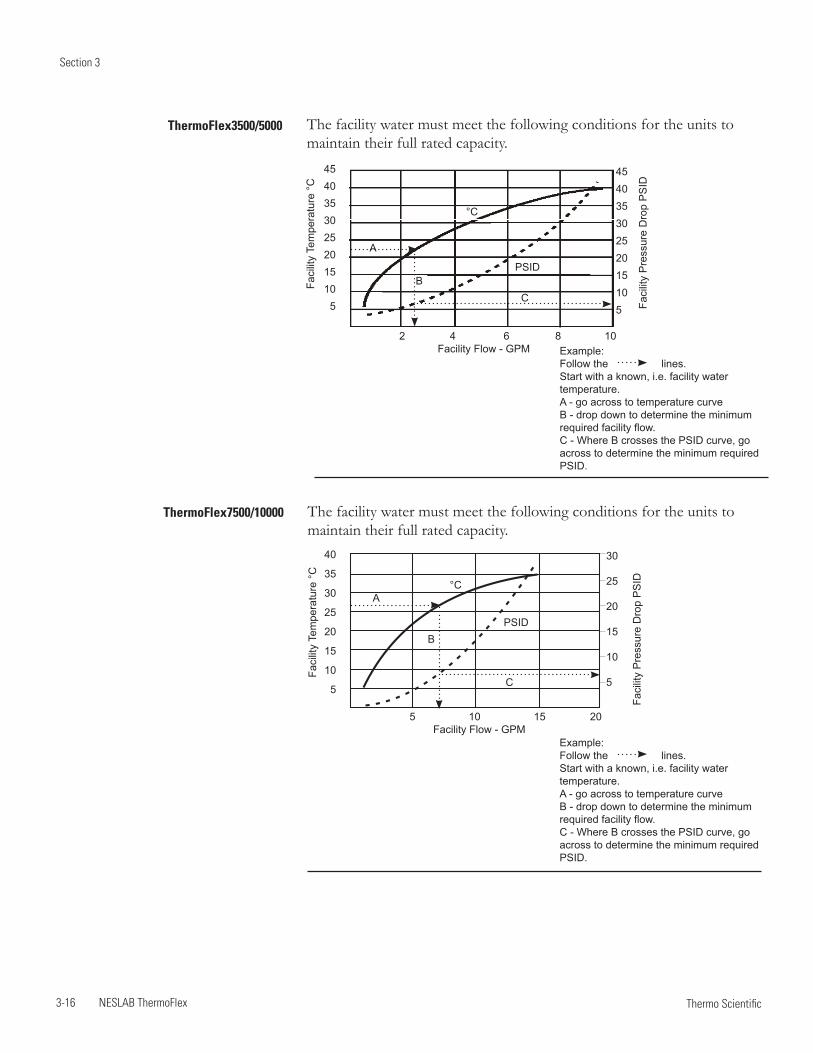
Section 3
3-16 NESLAB ThermoFlex Thermo Scientific
The facility water must meet the following conditions for the units to maintain their full rated capacity.
Faci
lity
Tem
pera
ture
°C
40
35
30
25
20
15
10
5
5 10 15 20 Facility Flow - GPM
Faci
lity
Pre
ssur
e D
rop
PS
ID
30
25
20
15
10
5
°C
PSID
The facility water must meet the following conditions for the units to maintain their full rated capacity.
Faci
lity
Tem
pera
ture
°C
45403530252015105
2 4 6 8 10 Facility Flow - GPM
Faci
lity
Pre
ssur
e D
rop
PS
ID
45403530252015105
°C
PSID
ThermoFlex3500/5000
ThermoFlex7500/10000
Example:Follow the lines.Start with a known, i.e. facility water temperature.A - go across to temperature curveB - drop down to determine the minimum required facility flow.C - Where B crosses the PSID curve, go across to determine the minimum required PSID.
Example:Follow the lines.Start with a known, i.e. facility water temperature.A - go across to temperature curveB - drop down to determine the minimum required facility flow.C - Where B crosses the PSID curve, go across to determine the minimum required PSID.
A
A
B
B
C
C
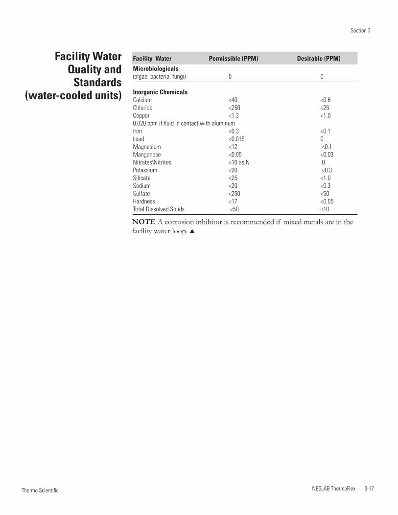
Section 3
NESLAB ThermoFlex 3-17 Thermo Scientific
Facility Water Quality and
Standards (water-cooled units)
Facility Water Permissible (PPM) Desirable (PPM)
Microbiologicals (algae, bacteria, fungi) 0 0
Inorganic ChemicalsCalcium <40 <0.6Chloride <250 <25 Copper <1.3 <1.00.020 ppm if fluid in contact with aluminumIron <0.3 <0.1Lead <0.015 0Magnesium <12 <0.1Manganese <0.05 <0.03Nitrates\Nitrites <10 as N 0Potassium <20 <0.3Silicate <25 <1.0Sodium <20 <0.3Sulfate <250 <50Hardness <17 <0.05Total Dissolved Solids <50 <10
NOTE A corrosion inhibitor is recommended if mixed metals are in the facility water loop.

Section 3
3-18 NESLAB ThermoFlex Thermo Scientific
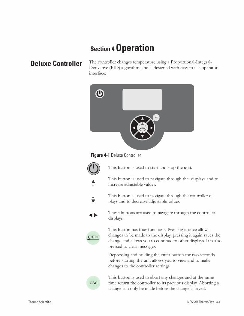
Thermo Scientific NESLAB ThermoFlex 4-1
Section 4
The controller changes temperature using a Proportional-Integral-Derivative (PID) algorithm, and is designed with easy to use operator interface.
Section 4 Operation
Deluxe Controller
This button is used to start and stop the unit.
This button is used to navigate through the displays and to increase adjustable values.
This button is used to navigate through the controller dis-plays and to decrease adjustable values.
These buttons are used to navigate through the controller displays.
This button has four functions. Pressing it once allows changes to be made to the display, pressing it again saves the change and allows you to continue to other displays. It is also pressed to clear messages.
Depressing and holding the enter button for two seconds before starting the unit allows you to view and to make changes to the controller settings.
This button is used to abort any changes and at the same time return the controller to its previous display. Aborting a change can only be made before the change is saved.
Figure 4-1 Deluxe Controller
enter
esc
+
-
+
-
esc
enter
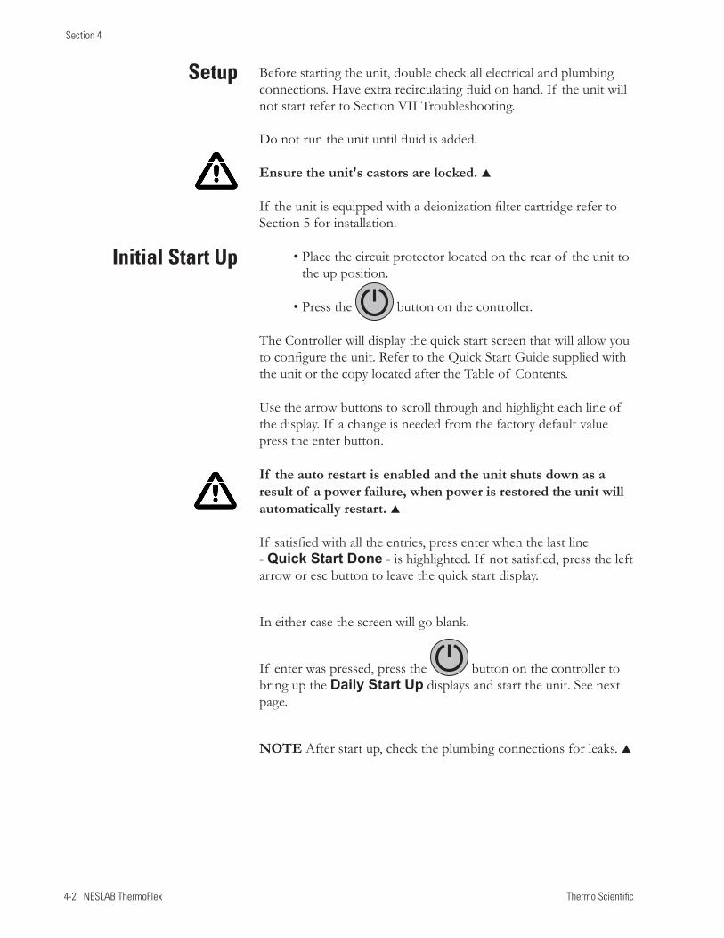
4-2 NESLAB ThermoFlex Thermo Scientific
Section 4
Before starting the unit, double check all electrical and plumbing connections. Have extra recirculating fluid on hand. If the unit will not start refer to Section VII Troubleshooting. Do not run the unit until fluid is added.
Ensure the unit's castors are locked.
If the unit is equipped with a deionization filter cartridge refer to Section 5 for installation.
• Place the circuit protector located on the rear of the unit to the up position.
• Press the button on the controller.
The Controller will display the quick start screen that will allow you to configure the unit. Refer to the Quick Start Guide supplied with the unit or the copy located after the Table of Contents.
Use the arrow buttons to scroll through and highlight each line of the display. If a change is needed from the factory default value press the enter button.
If the auto restart is enabled and the unit shuts down as a result of a power failure, when power is restored the unit will automatically restart.
If satisfied with all the entries, press enter when the last line - Quick Start Done - is highlighted. If not satisfied, press the left arrow or esc button to leave the quick start display.
In either case the screen will go blank.
If enter was pressed, press the button on the controller to bring up the Daily Start Up displays and start the unit. See next page.
NOTE After start up, check the plumbing connections for leaks.
Setup
Initial Start Up
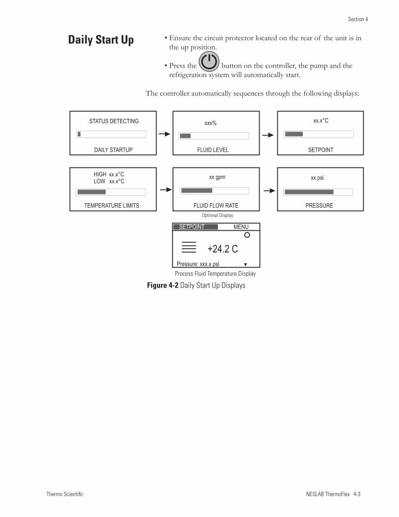
Thermo Scientific NESLAB ThermoFlex 4-3
Section 4
• Ensure the circuit protector located on the rear of the unit is in the up position.
• Press the button on the controller, the pump and the refrigeration system will automatically start.
The controller automatically sequences through the following displays:
Daily Start Up
Process Fluid Temperature Display
Optional Display
Figure 4-2 Daily Start Up Displays
FLUID LEVEL
xxx%
DAILY STARTUP
STATUS DETECTING
SETPOINT
xx.x°C
FLUID FLOW RATE
xx gpm
TEMPERATURE LIMITS
HIGH xx.x°CLOW xx.x°C
PRESSURE
xx psi
Pressure: xxx.x psi
+24.2 C
SETPOINT MENU
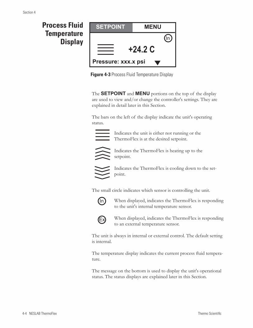
4-4 NESLAB ThermoFlex Thermo Scientific
Section 4
Process Fluid Temperature
Display
Figure 4-3 Process Fluid Temperature Display
In
Ex
+24.2 C
SETPOINT MENU
Pressure: xxx.x psi
In
The SETPOINT and MENU portions on the top of the display are used to view and/or change the controller's settings. They are explained in detail later in this Section.
The bars on the left of the display indicate the unit's operating status.
Indicates the unit is either not running or the ThermoFlex is at the desired setpoint.
Indicates the ThermoFlex is heating up to the setpoint.
Indicates the ThermoFlex is cooling down to the set-point.
The small circle indicates which sensor is controlling the unit.
When displayed, indicates the ThermoFlex is responding to the unit's internal temperature sensor.
When displayed, indicates the ThermoFlex is responding to an external temperature sensor.
The unit is always in internal or external control. The default setting is internal.
The temperature display indicates the current process fluid tempera-ture.
The message on the bottom is used to display the unit's operational status. The status displays are explained later in this Section.
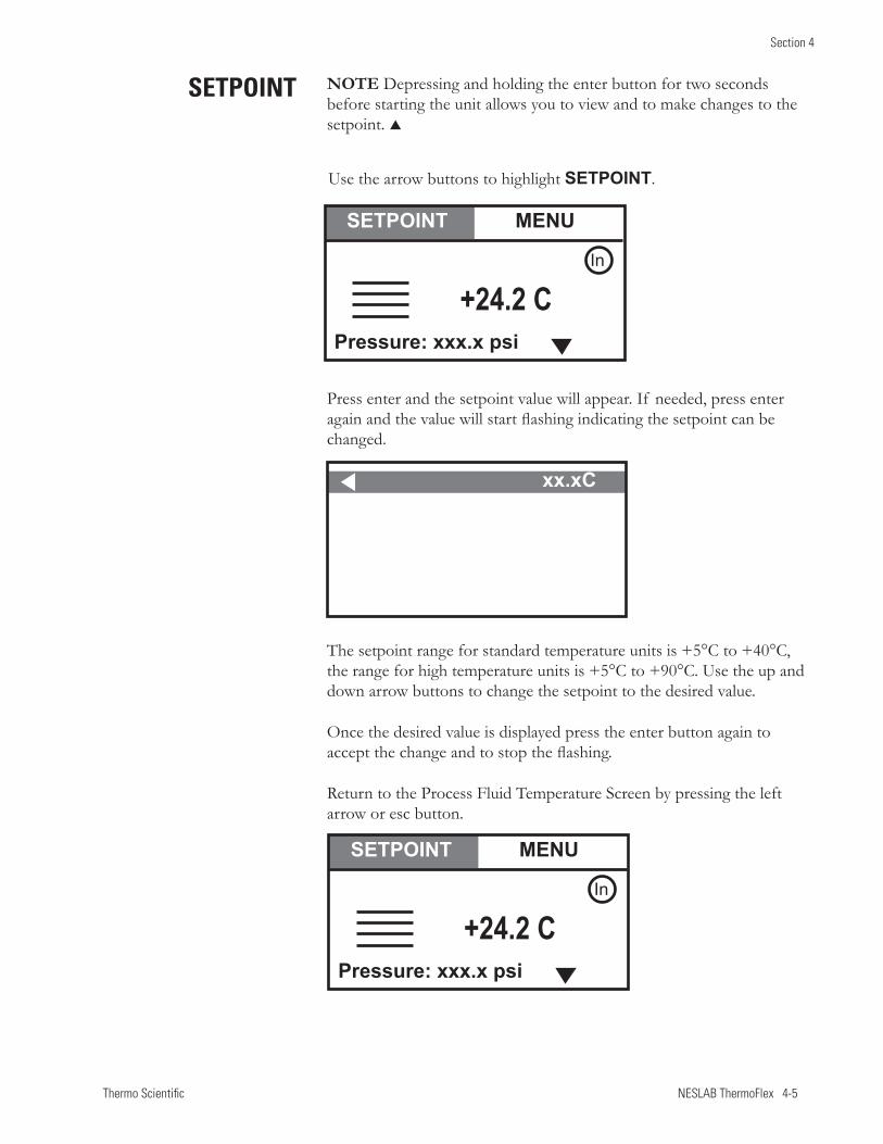
Thermo Scientific NESLAB ThermoFlex 4-5
Section 4
Use the arrow buttons to highlight SETPOINT.
Press enter and the setpoint value will appear. If needed, press enter again and the value will start flashing indicating the setpoint can be changed.
The setpoint range for standard temperature units is +5°C to +40°C, the range for high temperature units is +5°C to +90°C. Use the up and down arrow buttons to change the setpoint to the desired value.
Once the desired value is displayed press the enter button again to accept the change and to stop the flashing.
Return to the Process Fluid Temperature Screen by pressing the left arrow or esc button.
SETPOINT
xx.xC
+24.2 C
SETPOINT MENU
Pressure: xxx.x psi
In
+24.2 C
SETPOINT MENU
Pressure: xxx.x psi
In
NOTE Depressing and holding the enter button for two seconds before starting the unit allows you to view and to make changes to the setpoint.
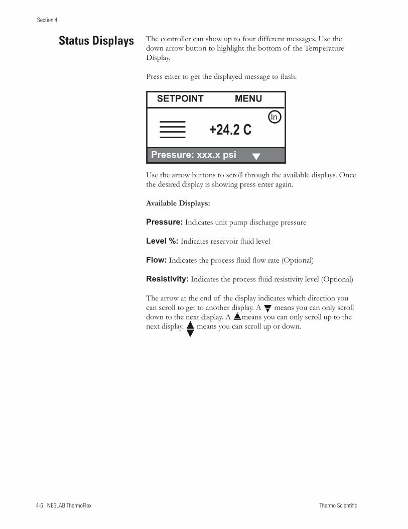
4-6 NESLAB ThermoFlex Thermo Scientific
Section 4
The controller can show up to four different messages. Use the down arrow button to highlight the bottom of the Temperature Display.
Press enter to get the displayed message to flash.
Status Displays
+24.2 C
SETPOINT MENU
Pressure: xxx.x psi
In
Use the arrow buttons to scroll through the available displays. Once the desired display is showing press enter again.
Available Displays:
Pressure: Indicates unit pump discharge pressure
Level %: Indicates reservoir fluid level
Flow: Indicates the process fluid flow rate (Optional)
Resistivity: Indicates the process fluid resistivity level (Optional)
The arrow at the end of the display indicates which direction you can scroll to get to another display. A means you can only scroll down to the next display. A means you can only scroll up to the next display. means you can scroll up or down.
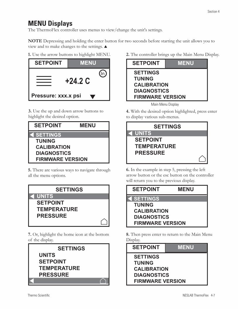
Thermo Scientific NESLAB ThermoFlex 4-7
Section 4
5. There are various ways to navigate through all the menu options.
3. Use the up and down arrow buttons to highlight the desired option.
4. With the desired option highlighted, press enter to display various sub-menus.
1. Use the arrow buttons to highlight MENU.
6. In the example in step 5, pressing the left arrow button or the esc button on the controller will return you to the previous display.
7. Or, highlight the home icon at the bottom of the display.
8. Then press enter to return to the Main Menu Display.
MENU Displays The ThermoFlex controller uses menus to view/change the unit's settings.
NOTE Depressing and holding the enter button for two seconds before starting the unit allows you to view and to make changes to the settings.
2. The controller brings up the Main Menu Display.
Main Menu Display
SETPOINT MENUSETTINGSTUNINGCALIBRATIONDIAGNOSTICS FIRMWARE VERSION
SETPOINT MENUSETTINGSTUNINGCALIBRATIONDIAGNOSTICS FIRMWARE VERSION
SETPOINT MENUSETTINGSTUNINGCALIBRATIONDIAGNOSTICS FIRMWARE VERSION
+24.2 C
SETPOINT MENU
Pressure: xxx.x psi
In
SETPOINT MENUSETTINGSTUNINGCALIBRATIONDIAGNOSTICS FIRMWARE VERSION
SETTINGSUNITSSETPOINTTEMPERATUREPRESSURE
SETTINGSUNITSSETPOINTTEMPERATUREPRESSURE
SETTINGSUNITSSETPOINTTEMPERATUREPRESSURE
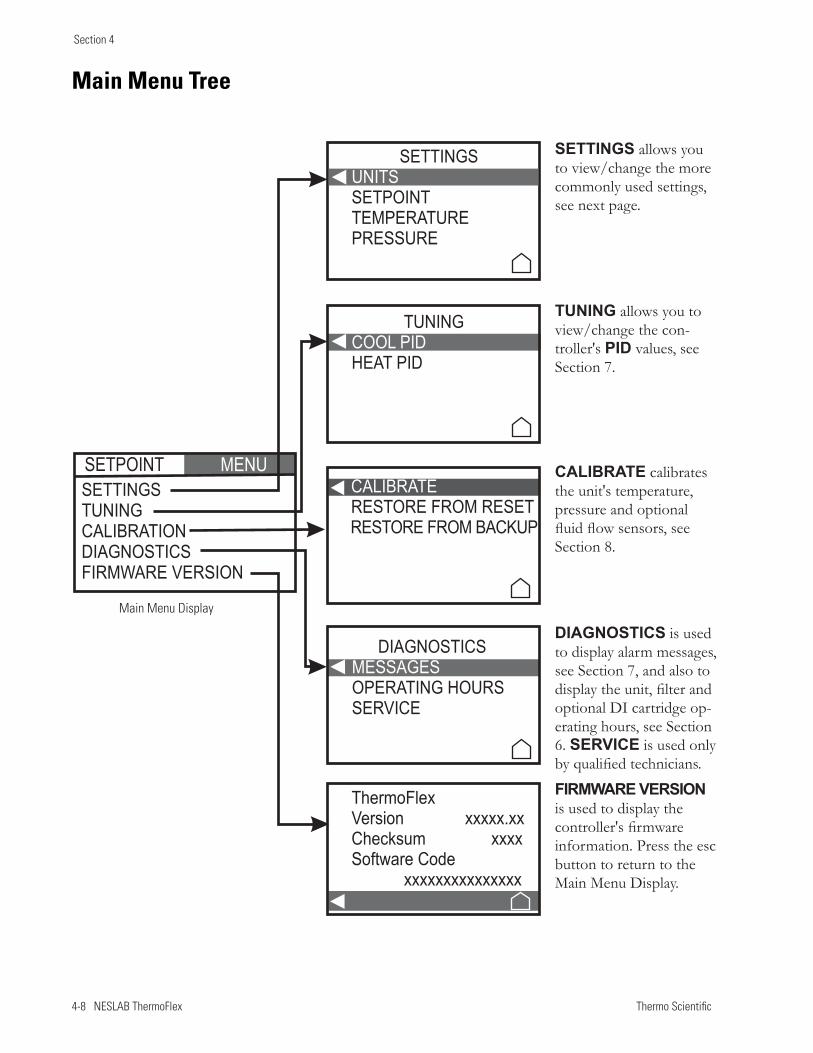
4-8 NESLAB ThermoFlex Thermo Scientific
Section 4
Main Menu Tree
SETTINGS allows you to view/change the more commonly used settings, see next page.
TUNING allows you to view/change the con-troller's PID values, see Section 7.
CALIBRATE calibrates the unit's temperature, pressure and optional fluid flow sensors, see Section 8.
DIAGNOSTICS is used to display alarm messages, see Section 7, and also to display the unit, filter and optional DI cartridge op-erating hours, see Section 6. SERVICE is used only by qualified technicians.
FIRMWARE VERSION is used to display the controller's firmware information. Press the esc button to return to the Main Menu Display.
Main Menu Display
MENUSETPOINTSETTINGSTUNINGCALIBRATIONDIAGNOSTICSFIRMWARE VERSION
SETTINGS
SETPOINTTEMPERATUREPRESSURE
UNITS
TUNING
HEAT PIDCOOL PID
CALIBRATERESTORE FROM RESETRESTORE FROM BACKUP
DIAGNOSTICS
OPERATING HOURSSERVICE
MESSAGES
ThermoFlexVersion xxxxx.xxChecksum xxxxSoftware Code
xxxxxxxxxxxxxxx
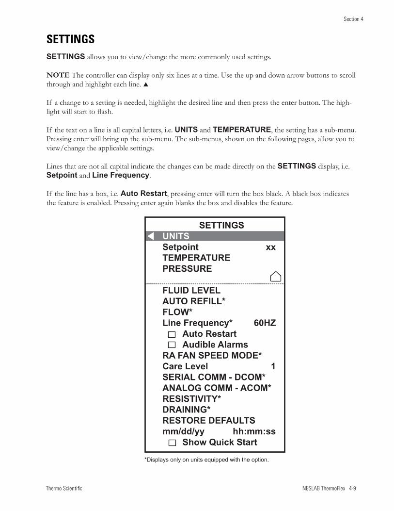
Thermo Scientific NESLAB ThermoFlex 4-9
Section 4
SETTINGS
SETTINGS allows you to view/change the more commonly used settings.
NOTE The controller can display only six lines at a time. Use the up and down arrow buttons to scroll through and highlight each line.
If a change to a setting is needed, highlight the desired line and then press the enter button. The high-light will start to flash.
If the text on a line is all capital letters, i.e. UNITS and TEMPERATURE, the setting has a sub-menu. Pressing enter will bring up the sub-menu. The sub-menus, shown on the following pages, allow you to view/change the applicable settings.
Lines that are not all capital indicate the changes can be made directly on the SETTINGS display, i.e. Setpoint and Line Frequency.
If the line has a box, i.e. Auto Restart, pressing enter will turn the box black. A black box indicates the feature is enabled. Pressing enter again blanks the box and disables the feature.
SETTINGSUNITSSetpoint xxTEMPERATUREPRESSURE
FLUID LEVELAUTO REFILL*FLOW*Line Frequency* 60HZ Auto Restart Audible AlarmsRA FAN SPEED MODE*Care Level 1SERIAL COMM - DCOM*ANALOG COMM - ACOM*RESISTIVITY*DRAINING*RESTORE DEFAULTSmm/dd/yy hh:mm:ss Show Quick Start
*Displays only on units equipped with the option.
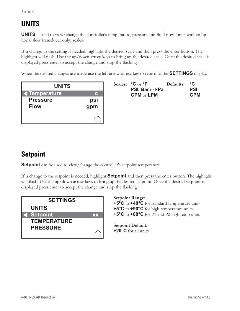
4-10 NESLAB ThermoFlex Thermo Scientific
Section 4
UNITS
UNITS is used to view/change the controller's temperature, pressure and fluid flow (units with an op-tional flow transducer only) scales.
If a change to the setting is needed, highlight the desired scale and then press the enter button. The highlight will flash. Use the up/down arrow keys to bring up the desired scale. Once the desired scale is displayed press enter to accept the change and stop the flashing.
When the desired changes are made use the left arrow or esc key to return to the SETTINGS display.
Setpoint
Setpoint can be used to view/change the controller's setpoint temperature.
If a change to the setpoint is needed, highlight Setpoint and then press the enter button. The highlight will flash. Use the up/down arrow keys to bring up the desired setpoint. Once the desired setpoint is displayed press enter to accept the change and stop the flashing.
Scales: °C or °F Defaults: °C PSI, Bar or kPa PSI GPM or LPM GPM
Setpoint Range: +5°C to +40°C for standard temperature units +5°C to +90°C for high temperature units, +5°C to +88°C for P1 and P2 high temp units
Setpoint Default: +20°C for all units
Temperature cPressure psiFlow gpm
UNITS
UNITSSetpoint xxTEMPERATURE PRESSURE
SETTINGS
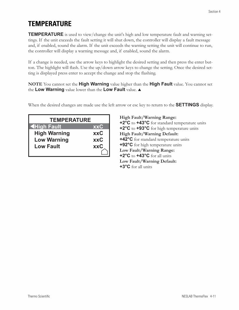
Thermo Scientific NESLAB ThermoFlex 4-11
Section 4
TEMPERATURE
TEMPERATURE is used to view/change the unit's high and low temperature fault and warning set-tings. If the unit exceeds the fault setting it will shut down, the controller will display a fault message and, if enabled, sound the alarm. If the unit exceeds the warning setting the unit will continue to run, the controller will display a warning message and, if enabled, sound the alarm.
If a change is needed, use the arrow keys to highlight the desired setting and then press the enter but-ton. The highlight will flash. Use the up/down arrow keys to change the setting. Once the desired set-ting is displayed press enter to accept the change and stop the flashing.
NOTE You cannot set the High Warning value higher than the High Fault value. You cannot set the Low Warning value lower than the Low Fault value.
When the desired changes are made use the left arrow or esc key to return to the SETTINGS display.
High Fault/Warning Range: +2°C to +43°C for standard temperature units +2°C to +93°C for high temperature unitsHigh Fault/Warning Default: +42°C for standard temperature units +92°C for high temperature unitsLow Fault/Warning Range: +2°C to +43°C for all units Low Fault/Warning Default: +3°C for all units
TEMPERATUREHigh Fault xxCHigh Warning xxCLow Warning xxCLow Fault xxC
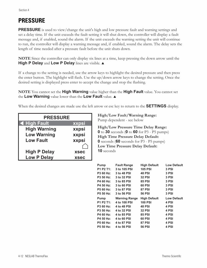
4-12 NESLAB ThermoFlex Thermo Scientific
Section 4
PRESSURE
PRESSURE is used to view/change the unit's high and low pressure fault and warning settings and set a delay time. If the unit exceeds the fault setting it will shut down, the controller will display a fault message and, if enabled, sound the alarm. If the unit exceeds the warning setting the unit will continue to run, the controller will display a warning message and, if enabled, sound the alarm. The delay sets the length of time needed after a pressure fault before the unit shuts down.
NOTE Since the controller can only display six lines at a time, keep pressing the down arrow until the High P Delay and Low P Delay lines are visible.
If a change to the setting is needed, use the arrow keys to highlight the desired pressure and then press the enter button. The highlight will flash. Use the up/down arrow keys to change the setting. Once the desired setting is displayed press enter to accept the change and stop the flashing.
NOTE You cannot set the High Warning value higher than the High Fault value. You cannot set the Low Warning value lower than the Low Fault value.
When the desired changes are made use the left arrow or esc key to return to the SETTINGS display.
High/Low Fault/Warning Range: Pump dependent - see below
High/Low Pressure Time Delay Range: 0 to 30 seconds (0 to 60 for P3 - P5 pumps)High Time Pressure Delay Default: 0 seconds (60 seconds for P3 - P5 pumps)Low Time Pressure Delay Default: 10 seconds
Pump Fault Range High Default Low DefaultP1 P2 T1: 3 to 105 PSI 105 PSI 3 PSIP3 60 Hz: 3 to 48 PSI 48 PSI 3 PSI P3 50 Hz: 3 to 32 PSI 32 PSI 3 PSI P4 60 Hz: 3 to 85 PSI 85 PSI 3 PSI P4 50 Hz: 3 to 60 PSI 60 PSI 3 PSIP5 60 Hz: 3 to 87 PSI 87 PSI 3 PSI P5 50 Hz: 3 to 56 PSI 56 PSI 3 PSIPump Warning Range High Default Low DefaultP1 P2 T1: 4 to 100 PSI 100 PSI 4 PSIP3 60 Hz: 4 to 48 PSI 48 PSI 4 PSI P3 50 Hz: 4 to 32 PSI 32 PSI 4 PSI P4 60 Hz: 4 to 85 PSI 85 PSI 4 PSI P4 50 Hz: 4 to 60 PSI 60 PSI 4 PSIP5 60 Hz: 4 to 87 PSI 87 PSI 4 PSI P5 50 Hz: 4 to 56 PSI 56 PSI 4 PSI
PRESSUREHigh Fault xxpsiHigh Warning xxpsiLow Warning xxpsiLow Fault xxpsi
High P Delay xsecLow P Delay xsec
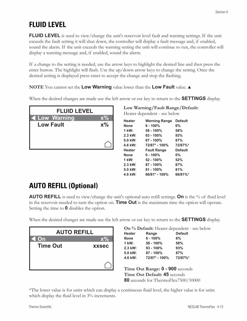
Thermo Scientific NESLAB ThermoFlex 4-13
Section 4
Heater Warning Range Default None 6 - 100% 6% 1 kW: 58 - 100% 58% 2.3 kW: 93 - 100% 93% 5.0 kW: 87 - 100% 87% 4.6 kW: 72/87* - 100% 72/87%* Heater Fault Range DefaultNone 0 - 100% 0% 1 kW: 52 - 100% 52%2.3 kW: 87 - 100% 87%5.0 kW: 81 - 100% 81%4.6 kW: 66/81* - 100% 66/81%*
FLUID LEVEL
FLUID LEVEL is used to view/change the unit's reservoir level fault and warning settings. If the unit exceeds the fault setting it will shut down, the controller will display a fault message and, if enabled, sound the alarm. If the unit exceeds the warning setting the unit will continue to run, the controller will display a warning message and, if enabled, sound the alarm.
If a change to the setting is needed, use the arrow keys to highlight the desired line and then press the enter button. The highlight will flash. Use the up/down arrow keys to change the setting. Once the desired setting is displayed press enter to accept the change and stop the flashing.
NOTE You cannot set the Low Warning value lower than the Low Fault value.
When the desired changes are made use the left arrow or esc key to return to the SETTINGS display.
AUTO REFILL (Optional)
AUTO REFILL is used to view/change the unit's optional auto refill settings. On is the % of fluid level in the reservoir needed to turn the option on. Time Out is the maximum time the option will operate. Setting the time to 0 disables the option.
When the desired changes are made use the left arrow or esc key to return to the SETTINGS display.
On % Default: Heater dependent - see belowHeater Range DefaultNone 6 - 100% 6% 1 kW: 58 - 100% 58%2.3 kW: 93 - 100% 93%5.0 kW: 87 - 100% 87%4.6 kW: 72/87* - 100% 72/87%*
Time Out Range: 0 - 900 secondsTime Out Default: 45 seconds 80 seconds for ThermoFlex7500/10000
FLUID LEVELLow Warning x%Low Fault x%
AUTO REFILLOn x%Time Out xxsec
Low Warning/Fault Range/Default: Heater dependent - see below
*The lower value is for units which can display a continuous fluid level, the higher value is for units which display the fluid level in 3% increments.
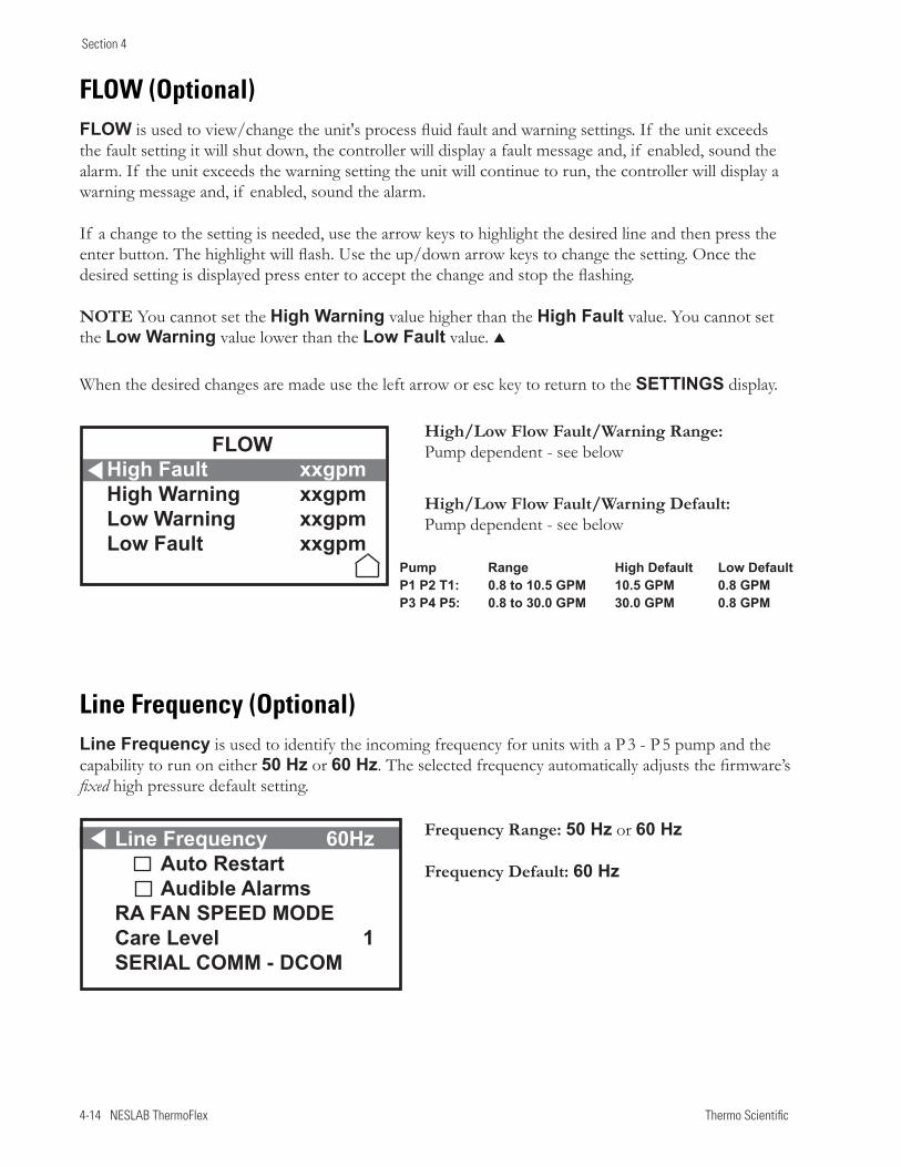
4-14 NESLAB ThermoFlex Thermo Scientific
Section 4
FLOW (Optional)
FLOW is used to view/change the unit's process fluid fault and warning settings. If the unit exceeds the fault setting it will shut down, the controller will display a fault message and, if enabled, sound the alarm. If the unit exceeds the warning setting the unit will continue to run, the controller will display a warning message and, if enabled, sound the alarm.
If a change to the setting is needed, use the arrow keys to highlight the desired line and then press the enter button. The highlight will flash. Use the up/down arrow keys to change the setting. Once the desired setting is displayed press enter to accept the change and stop the flashing.
NOTE You cannot set the High Warning value higher than the High Fault value. You cannot set the Low Warning value lower than the Low Fault value.
When the desired changes are made use the left arrow or esc key to return to the SETTINGS display.
Line Frequency (Optional)
Line Frequency is used to identify the incoming frequency for units with a P 3 - P 5 pump and the capability to run on either 50 Hz or 60 Hz. The selected frequency automatically adjusts the firmware’s fixed high pressure default setting.
High/Low Flow Fault/Warning Range: Pump dependent - see below
High/Low Flow Fault/Warning Default: Pump dependent - see below
Frequency Range: 50 Hz or 60 Hz
Frequency Default: 60 Hz
Pump Range High Default Low DefaultP1 P2 T1: 0.8 to 10.5 GPM 10.5 GPM 0.8 GPM P3 P4 P5: 0.8 to 30.0 GPM 30.0 GPM 0.8 GPM
Line Frequency 60Hz Auto Restart Audible AlarmsRA FAN SPEED MODECare Level 1SERIAL COMM - DCOM
FLOWHigh Fault xxgpmHigh Warning xxgpmLow Warning xxgpmLow Fault xxgpm
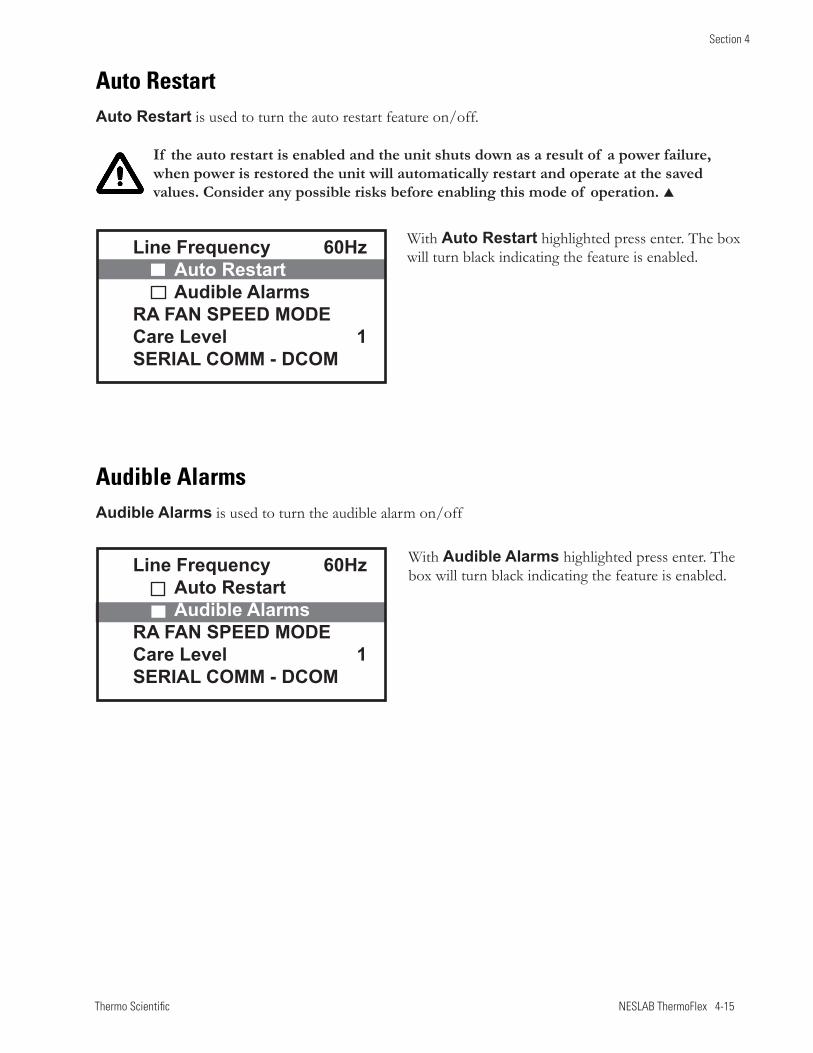
Thermo Scientific NESLAB ThermoFlex 4-15
Section 4
Auto RestartAuto Restart is used to turn the auto restart feature on/off.
If the auto restart is enabled and the unit shuts down as a result of a power failure, when power is restored the unit will automatically restart and operate at the saved values. Consider any possible risks before enabling this mode of operation.
Audible AlarmsAudible Alarms is used to turn the audible alarm on/off
With Auto Restart highlighted press enter. The box will turn black indicating the feature is enabled.
With Audible Alarms highlighted press enter. The box will turn black indicating the feature is enabled.
Line Frequency 60Hz Auto Restart Audible AlarmsRA FAN SPEED MODECare Level 1SERIAL COMM - DCOM
Line Frequency 60Hz Auto Restart Audible AlarmsRA FAN SPEED MODECare Level 1SERIAL COMM - DCOM
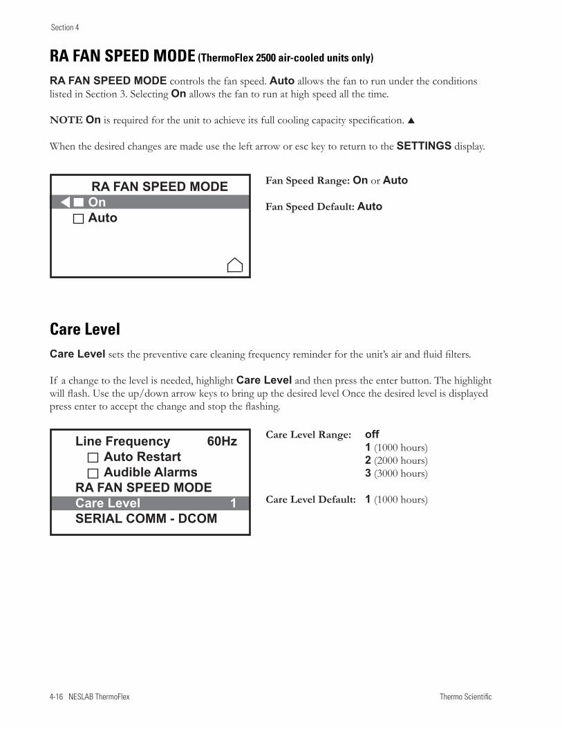
4-16 NESLAB ThermoFlex Thermo Scientific
Section 4
RA FAN SPEED MODE (ThermoFlex 2500 air-cooled units only)
RA FAN SPEED MODE controls the fan speed. Auto allows the fan to run under the conditions listed in Section 3. Selecting On allows the fan to run at high speed all the time.
NOTE On is required for the unit to achieve its full cooling capacity specification.
When the desired changes are made use the left arrow or esc key to return to the SETTINGS display.
Care LevelCare Level sets the preventive care cleaning frequency reminder for the unit’s air and fluid filters.
If a change to the level is needed, highlight Care Level and then press the enter button. The highlight will flash. Use the up/down arrow keys to bring up the desired level Once the desired level is displayed press enter to accept the change and stop the flashing.
Line Frequency 60Hz Auto Restart Audible AlarmsRA FAN SPEED MODECare Level 1SERIAL COMM - DCOM
Care Level Range: off 1 (1000 hours) 2 (2000 hours) 3 (3000 hours)
Care Level Default: 1 (1000 hours)
Fan Speed Range: On or Auto
Fan Speed Default: Auto
RA FAN SPEED MODEOnAuto
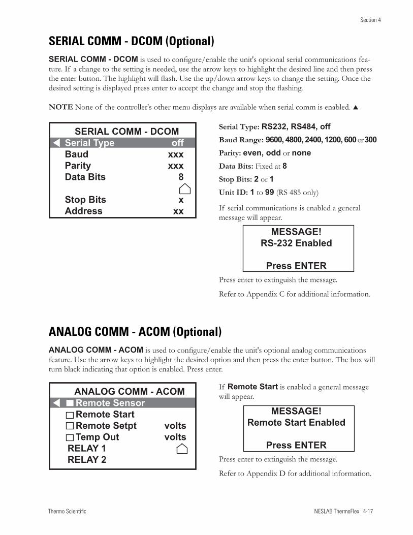
Thermo Scientific NESLAB ThermoFlex 4-17
Section 4
SERIAL COMM - DCOM (Optional)
SERIAL COMM - DCOM is used to configure/enable the unit's optional serial communications fea-ture. If a change to the setting is needed, use the arrow keys to highlight the desired line and then press the enter button. The highlight will flash. Use the up/down arrow keys to change the setting. Once the desired setting is displayed press enter to accept the change and stop the flashing.
NOTE None of the controller's other menu displays are available when serial comm is enabled.
Serial Type: RS232, RS484, offBaud Range: 9600, 4800, 2400, 1200, 600 or 300Parity: even, odd or noneData Bits: Fixed at 8Stop Bits: 2 or 1Unit ID: 1 to 99 (RS 485 only)
If serial communications is enabled a general message will appear.
Press enter to extinguish the message.
Refer to Appendix C for additional information.
MESSAGE!RS-232 Enabled
Press ENTER
SERIAL COMM - DCOMSerial Type offBaud xxxParity xxxData Bits 8
Stop Bits xAddress xx
ANALOG COMM - ACOM (Optional)
ANALOG COMM - ACOM is used to configure/enable the unit's optional analog communications feature. Use the arrow keys to highlight the desired option and then press the enter button. The box will turn black indicating that option is enabled. Press enter.
If Remote Start is enabled a general message will appear.
Press enter to extinguish the message.
Refer to Appendix D for additional information.
MESSAGE!Remote Start Enabled
Press ENTER
ANALOG COMM - ACOMRemote SensorRemote StartRemote Setpt voltsTemp Out volts
RELAY 1RELAY 2
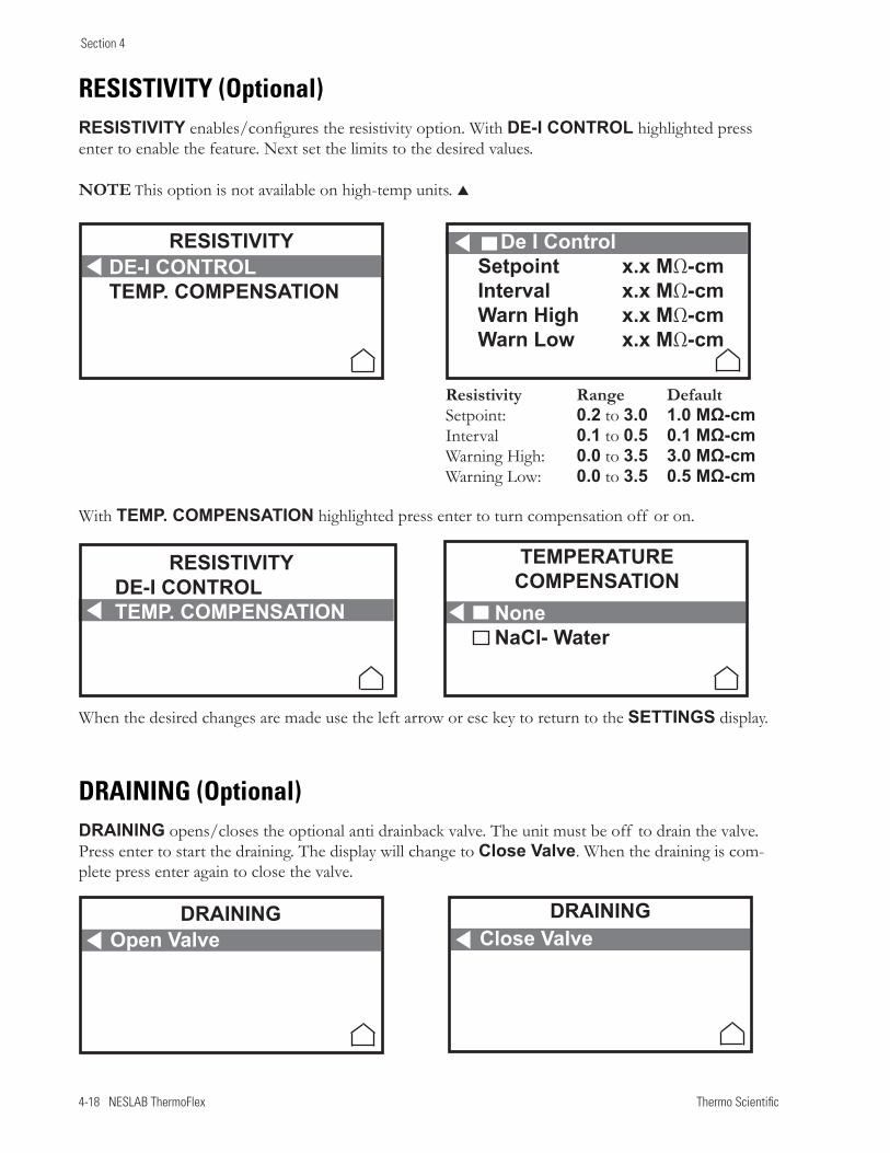
4-18 NESLAB ThermoFlex Thermo Scientific
Section 4
RESISTIVITY (Optional)RESISTIVITY enables/configures the resistivity option. With DE-I CONTROL highlighted press enter to enable the feature. Next set the limits to the desired values.
NOTE This option is not available on high-temp units.
DRAINING (Optional)DRAINING opens/closes the optional anti drainback valve. The unit must be off to drain the valve. Press enter to start the draining. The display will change to Close Valve. When the draining is com-plete press enter again to close the valve.
With TEMP. COMPENSATION highlighted press enter to turn compensation off or on.
Resistivity Range Default Setpoint: 0.2 to 3.0 1.0 MΩ-cm Interval 0.1 to 0.5 0.1 MΩ-cm Warning High: 0.0 to 3.5 3.0 MΩ-cm Warning Low: 0.0 to 3.5 0.5 MΩ-cm
When the desired changes are made use the left arrow or esc key to return to the SETTINGS display.
De I Control Setpoint x.x MΩ-cmInterval x.x MΩ-cmWarn High x.x MΩ-cmWarn Low x.x MΩ-cm
NoneNaCl- Water
TEMPERATURECOMPENSATION
RESISTIVITYDE-I CONTROLTEMP. COMPENSATION
RESISTIVITYDE-I CONTROLTEMP. COMPENSATION
DRAININGOpen Valve
DRAININGClose Valve
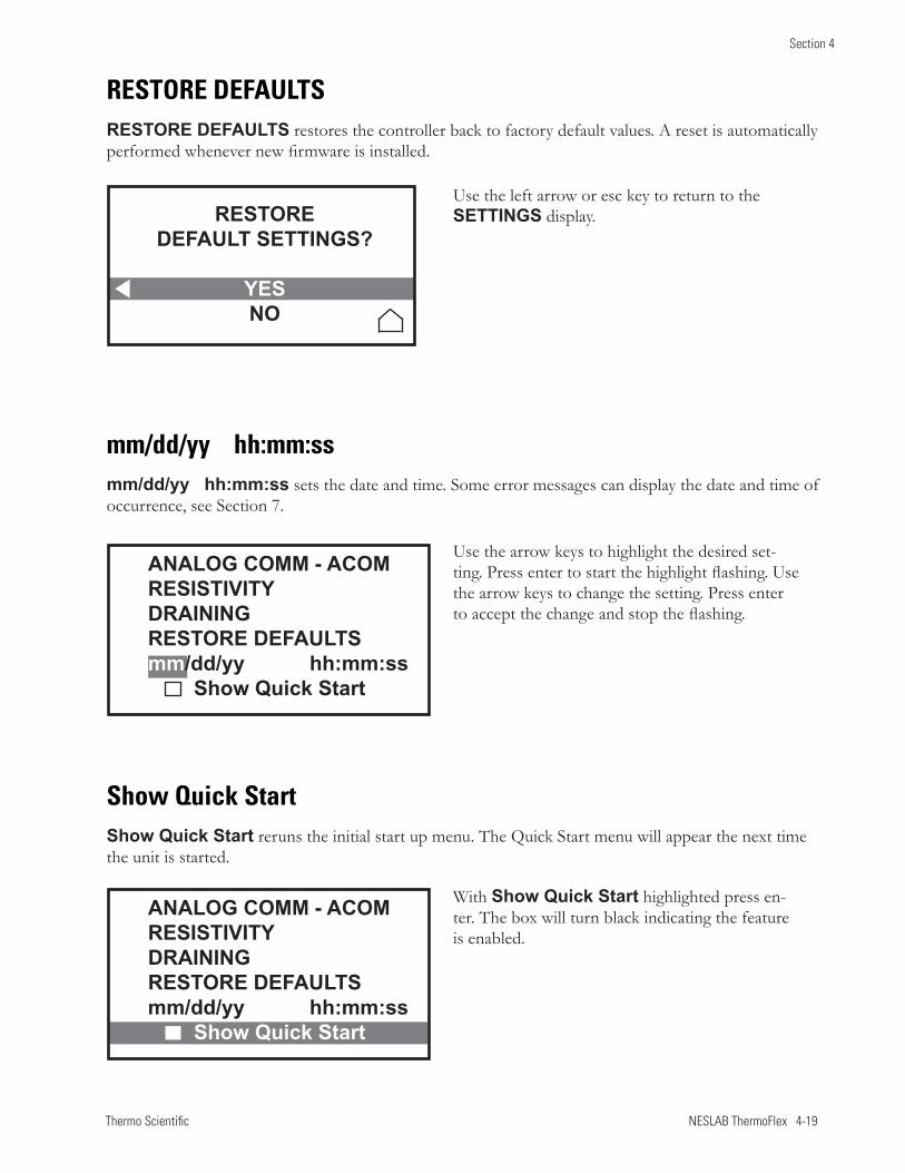
Thermo Scientific NESLAB ThermoFlex 4-19
Section 4
RESTORE DEFAULTSRESTORE DEFAULTS restores the controller back to factory default values. A reset is automatically performed whenever new firmware is installed.
mm/dd/yy hh:mm:ssmm/dd/yy hh:mm:ss sets the date and time. Some error messages can display the date and time of occurrence, see Section 7.
Show Quick StartShow Quick Start reruns the initial start up menu. The Quick Start menu will appear the next time the unit is started.
ANALOG COMM - ACOMRESISTIVITYDRAININGRESTORE DEFAULTSmm/dd/yy hh:mm:ss Show Quick Start
ANALOG COMM - ACOMRESISTIVITYDRAININGRESTORE DEFAULTSmm/dd/yy hh:mm:ss Show Quick Start
Use the arrow keys to highlight the desired set-ting. Press enter to start the highlight flashing. Use the arrow keys to change the setting. Press enter to accept the change and stop the flashing.
With Show Quick Start highlighted press en-ter. The box will turn black indicating the feature is enabled.
Use the left arrow or esc key to return to the SETTINGS display.RESTORE
DEFAULT SETTINGS?
YESNO
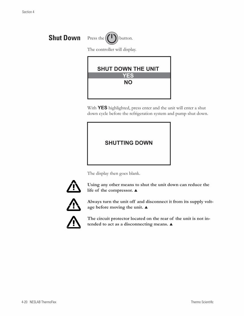
4-20 NESLAB ThermoFlex Thermo Scientific
Section 4
Press the button.
The controller will display.
Shut Down
With YES highlighted, press enter and the unit will enter a shut down cycle before the refrigeration system and pump shut down.
The display then goes blank.
Using any other means to shut the unit down can reduce the life of the compressor.
Always turn the unit off and disconnect it from its supply volt-age before moving the unit.
The circuit protector located on the rear of the unit is not in-tended to act as a disconnecting means.
SHUT DOWN THE UNITYESNO
SHUTTING DOWN
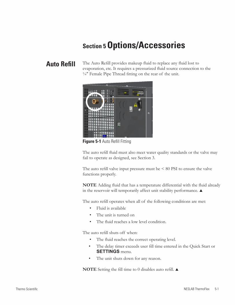
NESLAB ThermoFlex 5-1 Thermo Scientific
Auto Refill
Section 5 Options/Accessories
The Auto Refill provides makeup fluid to replace any fluid lost to evaporation, etc. It requires a pressurized fluid source connection to the ¼" Female Pipe Thread fitting on the rear of the unit.
Figure 5-1 Auto Refill Fitting
The auto refill fluid must also meet water quality standards or the valve may fail to operate as designed, see Section 3.
The auto refill valve input pressure must be < 80 PSI to ensure the valve functions properly.
NOTE Adding fluid that has a temperature differential with the fluid already in the reservoir will temporarily affect unit stability performance.
The auto refill operates when all of the following conditions are met: • Fluid is available • The unit is turned on • The fluid reaches a low level condition.
The auto refill shuts off when: • The fluid reaches the correct operating level.
• The delay timer exceeds user fill time entered in the Quick Start or SETTINGS menu.
• The unit shuts down for any reason.
NOTE Setting the fill time to 0 disables auto refill.
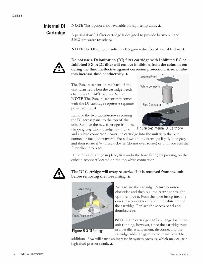
Section 5
5-2 NESLAB ThermoFlex Thermo Scientific
NOTE This option is not available on high-temp units.
A partial flow DI filter cartridge is designed to provide between 1 and 3 MΩ-cm water resistivity.
NOTE The DI option results in a 0.5 gpm reduction of available flow.
Do not use a Deionization (DI) filter cartridge with Inhibited EG or Inhibited PG. A DI filter will remove inhibitors from the solution ren-dering the fluid ineffective against corrosion protection. Also, inhibi-tors increase fluid conductivity.
The Puralite sensor on the back of the unit turns red when the cartridge needs changing (< 1 MΩ-cm), see Section 6. NOTE The Puralite sensor that comes with the DI cartridge requires a separate power source.
Remove the two thumbscrews securing the DI access panel to the top of the unit. Remove the new cartridge from the shipping bag. The cartridge has a blue and a white connector. Lower the cartridge into the unit with the blue connector facing downward. Press down on the cartridge lightly to engage and then rotate it ¼ turn clockwise (do not over rotate) or until you feel the filter click into place.
If there is a cartridge in place, first undo the hose fitting by pressing on the quick disconnect located on the top white connection.
The DI Cartridge will overpressurize if it is removed from the unit before removing the hose fitting.
Next rotate the cartridge ¼ turn counter-clockwise and then pull the cartridge straight up to remove it. Push the hose fitting into the quick disconnect located on the white end of the cartridge. Replace the access panel and thumbscrews.
NOTE The cartridge can be changed with the unit running, however, since the cartridge runs in a parallel arrangement, disconnecting the cartridge adds 0.5 gpm to the main flow. The
additional flow will cause an increase in system pressure which may cause a high fluid pressure fault.
Internal DI Cartridge
Quick Disconnect
Hose Fitting
Figure 5-3 DI Fittings
Figure 5-2 Internal DI Cartridge
Blue Connector
White Connector
Access Panel
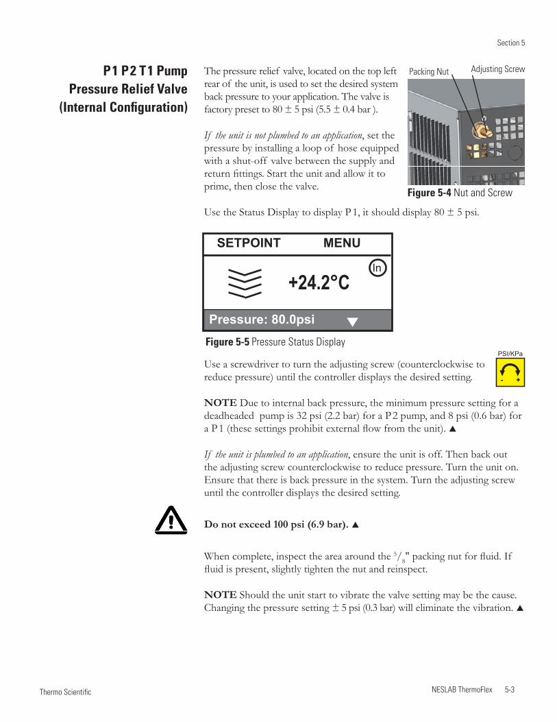
Section 5
NESLAB ThermoFlex 5-3 Thermo Scientific
P 1 P 2 T 1 Pump Pressure Relief Valve
(Internal Configuration)
The pressure relief valve, located on the top left rear of the unit, is used to set the desired system back pressure to your application. The valve is factory preset to 80 ± 5 psi (5.5 ± 0.4 bar ).
If the unit is not plumbed to an application, set the pressure by installing a loop of hose equipped with a shut-off valve between the supply and return fittings. Start the unit and allow it to prime, then close the valve.
Use the Status Display to display P 1, it should display 80 ± 5 psi.
Adjusting ScrewPacking Nut
Use a screwdriver to turn the adjusting screw (counterclockwise to reduce pressure) until the controller displays the desired setting.
NOTE Due to internal back pressure, the minimum pressure setting for a deadheaded pump is 32 psi (2.2 bar) for a P 2 pump, and 8 psi (0.6 bar) for a P 1 (these settings prohibit external flow from the unit).
If the unit is plumbed to an application, ensure the unit is off. Then back out the adjusting screw counterclockwise to reduce pressure. Turn the unit on. Ensure that there is back pressure in the system. Turn the adjusting screw until the controller displays the desired setting.
Do not exceed 100 psi (6.9 bar).
When complete, inspect the area around the 5/8" packing nut for fluid. If fluid is present, slightly tighten the nut and reinspect.
NOTE Should the unit start to vibrate the valve setting may be the cause. Changing the pressure setting ± 5 psi (0.3 bar) will eliminate the vibration.
Figure 5-4 Nut and Screw
- +
PSI/KPaFigure 5-5 Pressure Status Display
+24.2°C
SETPOINT MENU
Pressure: 80.0psi
In
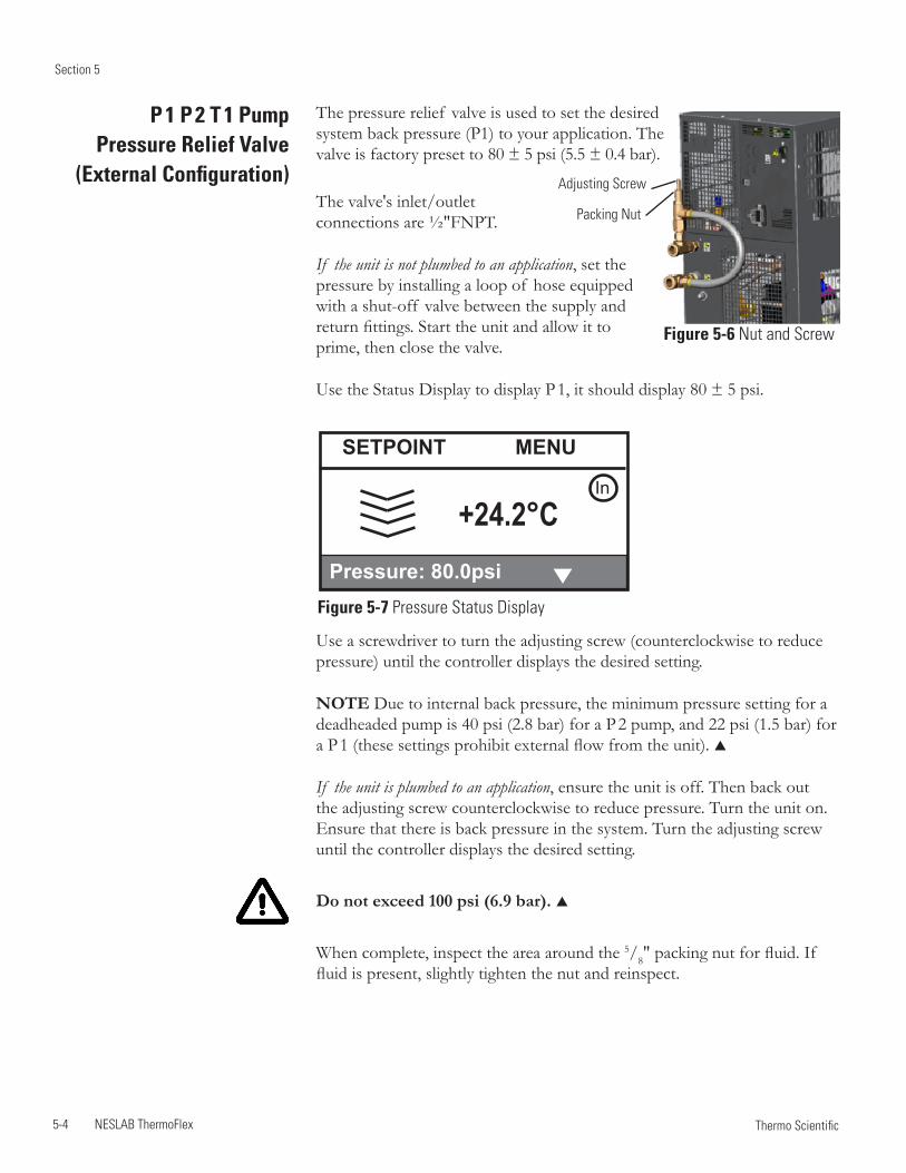
Section 5
5-4 NESLAB ThermoFlex Thermo Scientific
Figure 5-7 Pressure Status Display
P 1 P 2 T 1 Pump Pressure Relief Valve
(External Configuration)
The pressure relief valve is used to set the desired system back pressure (P1) to your application. The valve is factory preset to 80 ± 5 psi (5.5 ± 0.4 bar).
The valve's inlet/outlet connections are ½"FNPT.
If the unit is not plumbed to an application, set the pressure by installing a loop of hose equipped with a shut-off valve between the supply and return fittings. Start the unit and allow it to prime, then close the valve.
Use the Status Display to display P 1, it should display 80 ± 5 psi.
Packing Nut
Adjusting Screw
Figure 5-6 Nut and Screw
Use a screwdriver to turn the adjusting screw (counterclockwise to reduce pressure) until the controller displays the desired setting.
NOTE Due to internal back pressure, the minimum pressure setting for a deadheaded pump is 40 psi (2.8 bar) for a P 2 pump, and 22 psi (1.5 bar) for a P 1 (these settings prohibit external flow from the unit).
If the unit is plumbed to an application, ensure the unit is off. Then back out the adjusting screw counterclockwise to reduce pressure. Turn the unit on. Ensure that there is back pressure in the system. Turn the adjusting screw until the controller displays the desired setting.
Do not exceed 100 psi (6.9 bar).
When complete, inspect the area around the 5/8" packing nut for fluid. If fluid is present, slightly tighten the nut and reinspect.
+24.2°C
SETPOINT MENU
Pressure: 80.0psi
In
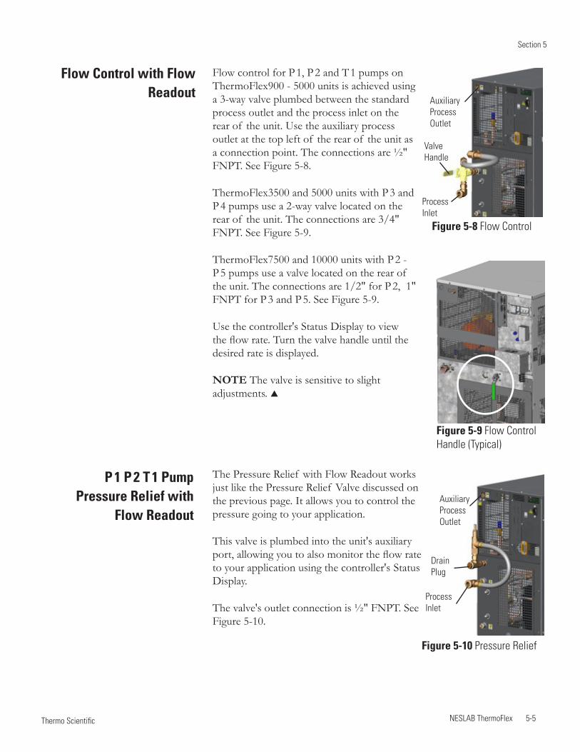
Section 5
NESLAB ThermoFlex 5-5 Thermo Scientific
Flow control for P 1, P 2 and T 1 pumps on ThermoFlex900 - 5000 units is achieved using a 3-way valve plumbed between the standard process outlet and the process inlet on the rear of the unit. Use the auxiliary process outlet at the top left of the rear of the unit as a connection point. The connections are ½" FNPT. See Figure 5-8.
ThermoFlex3500 and 5000 units with P 3 and P 4 pumps use a 2-way valve located on the rear of the unit. The connections are 3/4" FNPT. See Figure 5-9.
ThermoFlex7500 and 10000 units with P 2 - P 5 pumps use a valve located on the rear of the unit. The connections are 1/2" for P 2, 1" FNPT for P 3 and P 5. See Figure 5-9.
Use the controller's Status Display to view the flow rate. Turn the valve handle until the desired rate is displayed.
NOTE The valve is sensitive to slight adjustments.
The Pressure Relief with Flow Readout works just like the Pressure Relief Valve discussed on the previous page. It allows you to control the pressure going to your application.
This valve is plumbed into the unit's auxiliary port, allowing you to also monitor the flow rate to your application using the controller's Status Display.
The valve's outlet connection is ½" FNPT. See Figure 5-10.
Flow Control with Flow Readout
P 1 P 2 T 1 Pump Pressure Relief with
Flow Readout
Figure 5-8 Flow Control
Valve Handle
Auxiliary Process Outlet
Process Inlet
Figure 5-9 Flow Control Handle (Typical)
Figure 5-10 Pressure Relief
Drain Plug
Auxiliary Process Outlet
Process Inlet
Section 5
5-6 NESLAB ThermoFlex Thermo Scientific
ComplianceSEMI units are compliant with: SEMI S2-0703 Product Safety Assessment SEMI S8-0705 Ergonomic Assessment SEMI S14-0704 Fire Risk Assessment SEMI F47-0706
Emergency Off (EMO) A guarded red mushroom shaped push-button switch with twist-to-reset is provided on the unit's front to turn it off in case of an emergency. The button head is engraved with “EMO” in large white filled letters.
NOTE The EMO is controlled by a safety circuit and is not influenced by the unit's firmware/software.
Activation of the EMO button will remove power from the main contactor coil stopping operation of the unit. The controller will display External EMO.
Resetting the EMO button will not restart the unit. After all hazards have been removed reset the unit by pushing the enter key on the controller. In the local mode, the unit will restart by pressing the START STOP button again. In the serial communications mode, send the appropriate start command. In the analog I/O mode, the unit starts when the error is cleared.
Unit Circuit Breaker Interrupt Rating The main power circuit breaker located on the rear of the unit has an Interrupting Capacity (AIC) of 10,000 amps.
Semiconductor Equipment and
Materials International
(SEMI) Units
Units installed below the end-user application may allow system fluid to drain back into the chiller and cause spillage. The anti-drainback valve is designed to prevent any such spillage.
The valve opens just before the pump is turned on and it closes just after the pump shuts off.
This option is required if your unit is more than 24 feet below your application, or if there is a possibility of drain back due to the occasional opening of the process lines for either application swaps or unit servicing.
Anti Drainback
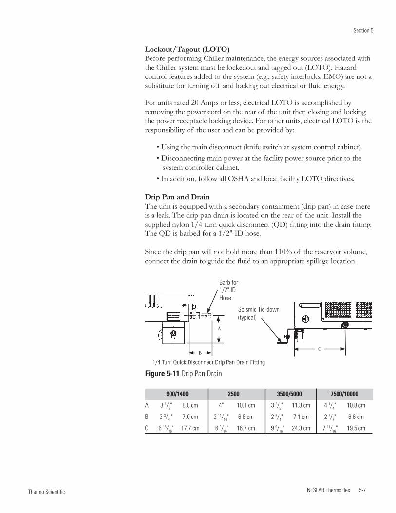
Section 5
NESLAB ThermoFlex 5-7 Thermo Scientific
A
B
1/4 Turn Quick Disconnect Drip Pan Drain Fitting
C
Barb for 1/2" ID Hose
900/1400 2500 3500/5000 7500/10000
A 3 1/2" 8.8 cm 4" 10.1 cm 3 3/8" 11.3 cm 4 1/4" 10.8 cm
B 2 3/4 " 7.0 cm 2 11/16" 6.8 cm 2 3/4" 7.1 cm 2 5/8" 6.6 cm
C 6 15/16" 17.7 cm 6 9/16" 16.7 cm 9 9/16" 24.3 cm 7 11/16" 19.5 cm
Figure 5-11 Drip Pan Drain
Seismic Tie-down (typical)
Lockout/Tagout (LOTO) Before performing Chiller maintenance, the energy sources associated with the Chiller system must be lockedout and tagged out (LOTO). Hazard control features added to the system (e.g., safety interlocks, EMO) are not a substitute for turning off and locking out electrical or fluid energy.
For units rated 20 Amps or less, electrical LOTO is accomplished by removing the power cord on the rear of the unit then closing and locking the power receptacle locking device. For other units, electrical LOTO is the responsibility of the user and can be provided by:
• Using the main disconnect (knife switch at system control cabinet). • Disconnecting main power at the facility power source prior to the system controller cabinet. • In addition, follow all OSHA and local facility LOTO directives.
Drip Pan and Drain The unit is equipped with a secondary containment (drip pan) in case there is a leak. The drip pan drain is located on the rear of the unit. Install the supplied nylon 1/4 turn quick disconnect (QD) fitting into the drain fitting. The QD is barbed for a 1/2" ID hose.
Since the drip pan will not hold more than 110% of the reservoir volume, connect the drain to guide the fluid to an appropriate spillage location.
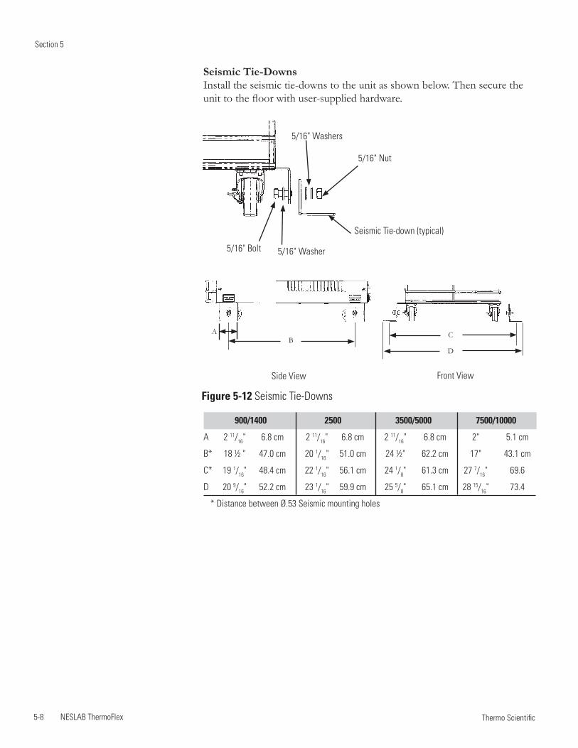
Section 5
5-8 NESLAB ThermoFlex Thermo Scientific
D
AB
C
Front ViewSide View
900/1400 2500 3500/5000 7500/10000
A 2 11/16" 6.8 cm 2 11/16" 6.8 cm 2 11/16" 6.8 cm 2" 5.1 cm
B* 18 ½ " 47.0 cm 20 1/16" 51.0 cm 24 ½" 62.2 cm 17" 43.1 cm
C* 19 1/16" 48.4 cm 22 1/16" 56.1 cm 24 1/8" 61.3 cm 27 7/16" 69.6
D 20 9/16" 52.2 cm 23 1/16" 59.9 cm 25 5/8" 65.1 cm 28 15/16" 73.4
* Distance between Ø.53 Seismic mounting holes
Figure 5-12 Seismic Tie-Downs
5/16" Bolt
5/16" Nut
5/16" Washer
5/16" Washers
Seismic Tie-Downs Install the seismic tie-downs to the unit as shown below. Then secure the unit to the floor with user-supplied hardware.
Seismic Tie-down (typical)
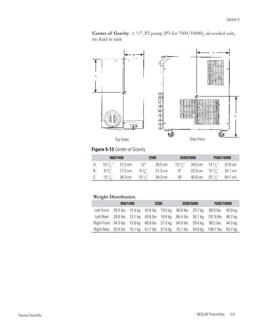
Section 5
NESLAB ThermoFlex 5-9 Thermo Scientific
Center of Gravity ± ½", P2 pump (P3 for 7500/10000), air-cooled unit, no fluid in tank
Top View
A
AB
C
Side View
Figure 5-13 Center of Gravity
900/1400 2500 3500/5000 7500/10000
A 10 3/4 " 27.3 cm 12" 30.5 cm 13 3/8" 34.0 cm 14 7/8" 37.8 cm
B 6 3/4" 17.2 cm 8 3/8" 21.3 cm 9" 22.9 cm 12 5/8" 32.1 cm
C 13 1/2" 34.3 cm 13 1/2" 34.3 cm 16" 40.6 cm 25 1/4" 64.1 cm
Weight Distribution900/1400 2500 3500/5000 7500/10000
Left Front 29.5 lbs 13.4 kg 42.8 lbs 19.5 kg 56.6 lbs 25.7 kg 99.3 lbs 45.0 kg
Left Rear 28.8 lbs 13.1 kg 43.6 lbs 19.8 kg 66.4 lbs 30.1 kg 101.9 lbs 46.2 kg
Right Front 34.3 lbs 15.6 kg 46.9 lbs 21.3 kg 64.9 lbs 29.4 kg 98.2 lbs 44.5 kg
Right Rear 33.4 lbs 15.1 kg 47.7 lbs 21.6 kg 76.1 lbs 34.6 kg 100.7 lbs 45.7 kg
Section 5
5-10 NESLAB ThermoFlex Thermo Scientific
Installation kit - includes replacement air and fluid filters
Maintenance kit - includes a set of hoses, adaptor fittings and Teflon® tape
Fluids
Fluid treatment kit
Please contact Thermo Fisher Scientific's Sales, Service and Customer Support to assist you with questions that you may have regarding accessories for your ThermoFlex, see inside front cover for contact information.
Other Accessories
NESLAB ThermoFlex 6-1 Thermo Scientific
Preventive Maintenance Timer
(Care Level)
Section 6 Preventive Maintenance
The ThermoFlex chiller has an integrated preventive maintenance timer that will alert you when it is time to perform preventive maintenance. This unique feature will remind you to change your air and fluid filters.
Based on the environment in which your chiller is located, you can choose from four levels of preventive maintenance off, L1, L2, and L3:
• off – Disables the alert • L1 – 1,000 hours - default setting · Heavy manufacturing environment · Airborne particulate created during manufacturing process • L2 – 2,000 hours · Typical production environment • L3 – 3,000 hours · Clean environment – filtered air · Typically laboratory or research environment
Change/set the level using the controller's DIAGNOSTICS menu, see next page. When the unit exceeds the chosen limit, the controller will flash Filter PM and, if enabled, an audible alarm will sound.
To clear this message press . This will automatically restart the preventive maintenance timer for your filters. Each time the unit exceeds the chosen time, the controller will remind you that it is time to change your filters.
If you change your filters before the preventive timer trips, you can clear the timer by using the controller's DIAGNOSTICS menu, see next page.
NOTE For air-cooled units, both the air and fluid filters in the ThermoFlex can be changed while the unit is running. For water-cooled units, only the fluid filter can be changed while the unit is running.
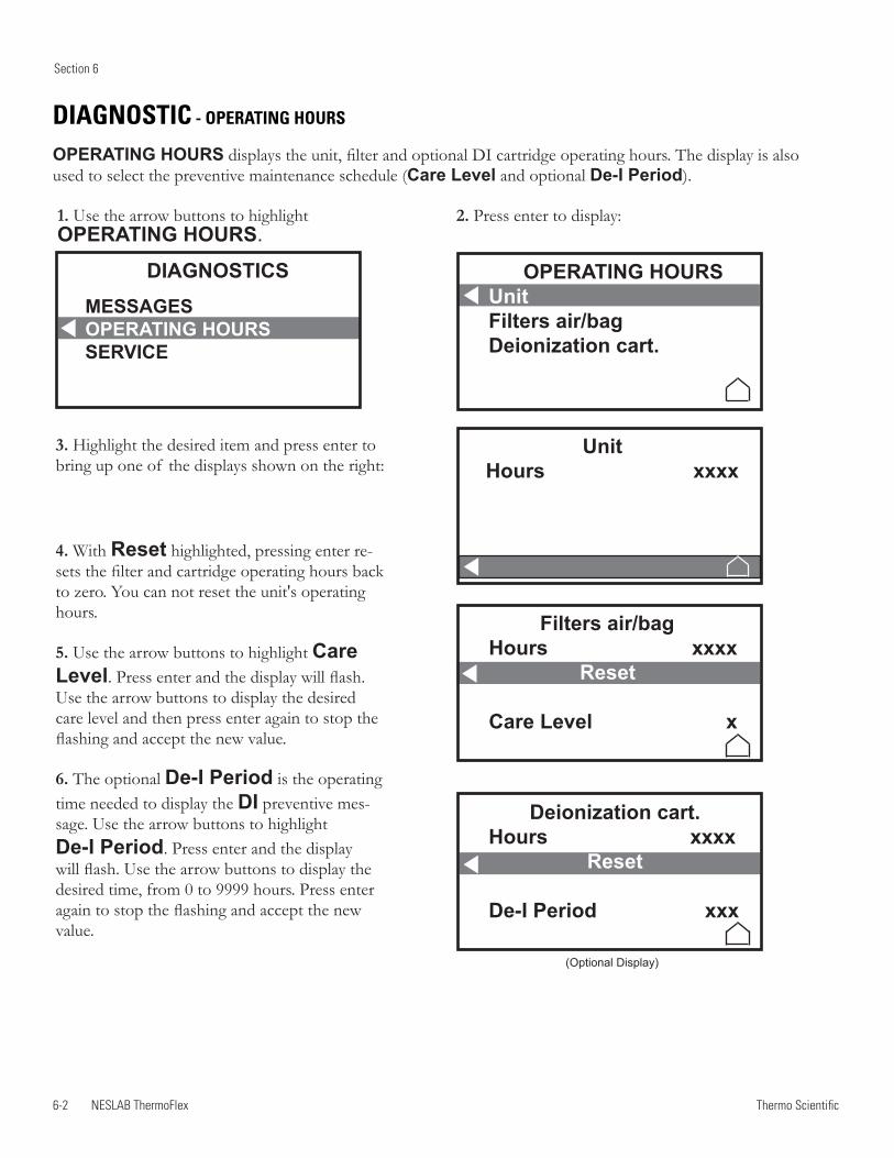
6-2 NESLAB ThermoFlex
Section 6
Thermo Scientific
1. Use the arrow buttons to highlight OPERATING HOURS.
2. Press enter to display:
3. Highlight the desired item and press enter to bring up one of the displays shown on the right:
4. With Reset highlighted, pressing enter re-sets the filter and cartridge operating hours back to zero. You can not reset the unit's operating hours.
5. Use the arrow buttons to highlight Care Level. Press enter and the display will flash. Use the arrow buttons to display the desired care level and then press enter again to stop the flashing and accept the new value.
6. The optional De-I Period is the operating time needed to display the DI preventive mes-sage. Use the arrow buttons to highlight De-I Period. Press enter and the display will flash. Use the arrow buttons to display the desired time, from 0 to 9999 hours. Press enter again to stop the flashing and accept the new value.
DIAGNOSTIC - OPERATING HOURS
OPERATING HOURS displays the unit, filter and optional DI cartridge operating hours. The display is also used to select the preventive maintenance schedule (Care Level and optional De-I Period).
DIAGNOSTICSMESSAGESOPERATING HOURSSERVICE
UnitHours xxxx
OPERATING HOURSUnitFilters air/bagDeionization cart.
Filters air/bagHours xxxx Reset
Care Level x
Deionization cart.Hours xxxx
Reset
De-I Period xxx
(Optional Display)
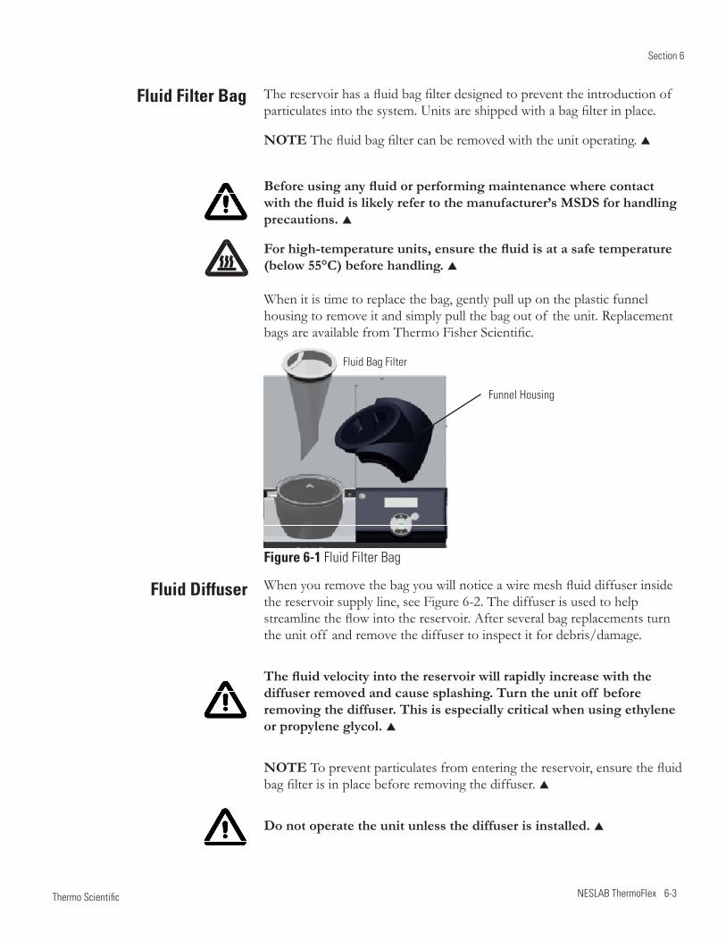
Section 6
NESLAB ThermoFlex 6-3 Thermo Scientific
Figure 6-1 Fluid Filter Bag
The reservoir has a fluid bag filter designed to prevent the introduction of particulates into the system. Units are shipped with a bag filter in place.
NOTE The fluid bag filter can be removed with the unit operating.
Before using any fluid or performing maintenance where contact with the fluid is likely refer to the manufacturer’s MSDS for handling precautions.
For high-temperature units, ensure the fluid is at a safe temperature (below 55°C) before handling.
When it is time to replace the bag, gently pull up on the plastic funnel housing to remove it and simply pull the bag out of the unit. Replacement bags are available from Thermo Fisher Scientific.
Fluid Filter Bag
When you remove the bag you will notice a wire mesh fluid diffuser inside the reservoir supply line, see Figure 6-2. The diffuser is used to help streamline the flow into the reservoir. After several bag replacements turn the unit off and remove the diffuser to inspect it for debris/damage.
The fluid velocity into the reservoir will rapidly increase with the diffuser removed and cause splashing. Turn the unit off before removing the diffuser. This is especially critical when using ethylene or propylene glycol.
NOTE To prevent particulates from entering the reservoir, ensure the fluid bag filter is in place before removing the diffuser.
Do not operate the unit unless the diffuser is installed.
Fluid Bag Filter
Funnel Housing
Fluid Diffuser
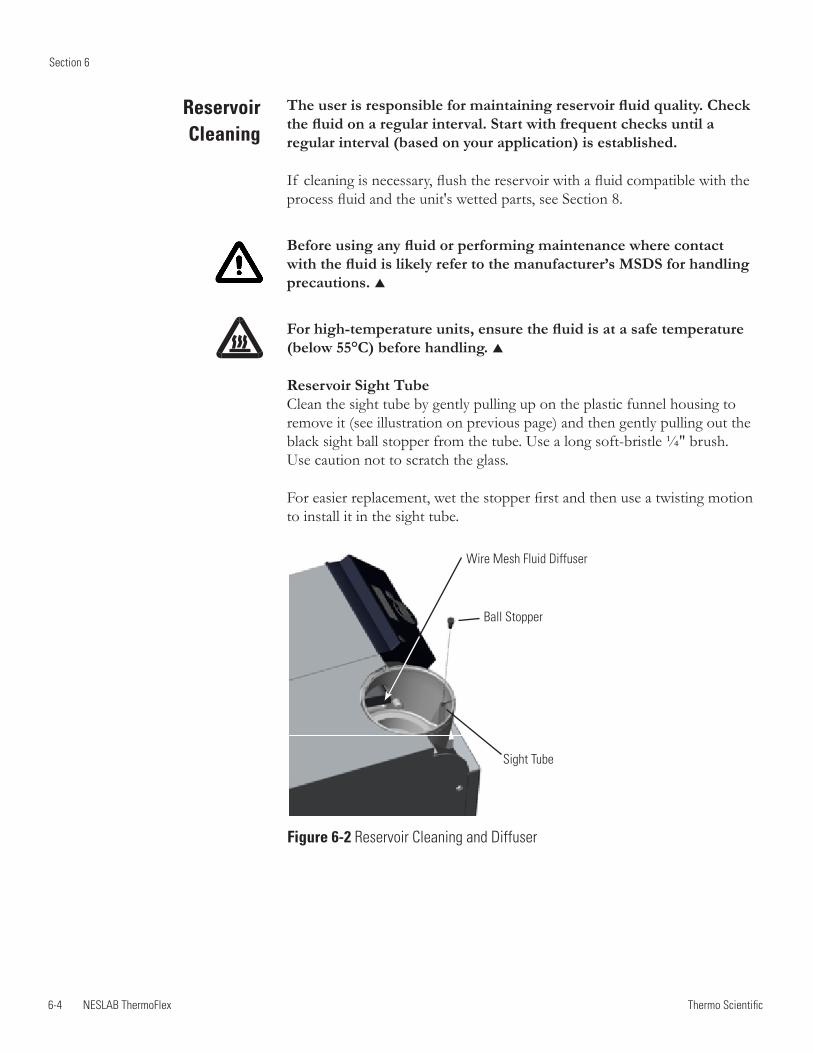
6-4 NESLAB ThermoFlex
Section 6
Thermo Scientific
Reservoir Cleaning
The user is responsible for maintaining reservoir fluid quality. Check the fluid on a regular interval. Start with frequent checks until a regular interval (based on your application) is established.
If cleaning is necessary, flush the reservoir with a fluid compatible with the process fluid and the unit's wetted parts, see Section 8.
Before using any fluid or performing maintenance where contact with the fluid is likely refer to the manufacturer’s MSDS for handling precautions.
For high-temperature units, ensure the fluid is at a safe temperature (below 55°C) before handling.
Reservoir Sight Tube Clean the sight tube by gently pulling up on the plastic funnel housing to remove it (see illustration on previous page) and then gently pulling out the black sight ball stopper from the tube. Use a long soft-bristle ¼" brush. Use caution not to scratch the glass.
For easier replacement, wet the stopper first and then use a twisting motion to install it in the sight tube.
Wire Mesh Fluid Diffuser
Sight Tube
Ball Stopper
Figure 6-2 Reservoir Cleaning and Diffuser
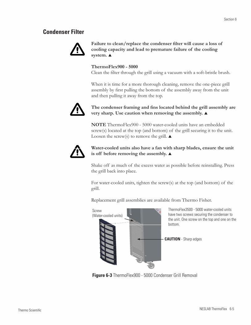
Section 6
NESLAB ThermoFlex 6-5 Thermo Scientific
Condenser Filter
Failure to clean/replace the condenser filter will cause a loss of cooling capacity and lead to premature failure of the cooling system.
ThermoFlex900 - 5000 Clean the filter through the grill using a vacuum with a soft-bristle brush.
When it is time for a more thorough cleaning, remove the one-piece grill assembly by first pulling the bottom of the assembly away from the unit and then pulling it away from the top.
The condenser framing and fins located behind the grill assembly are very sharp. Use caution when removing the assembly.
NOTE ThermoFlex900 - 5000 water-cooled units have an embedded screw(s) located at the top (and bottom) of the grill securing it to the unit. Loosen the screw(s) to remove the grill.
Water-cooled units also have a fan with sharp blades, ensure the unit is off before removing the assembly.
Shake off as much of the excess water as possible before reinstalling. Press the grill back into place.
For water-cooled units, tighten the screw(s) at the top (and bottom) of the grill.
Replacement grill assemblies are available from Thermo Fisher.
Screw (Water-cooled units)
CAUTION - Sharp edges
Figure 6-3 ThermoFlex900 - 5000 Condenser Grill Removal
ThermoFlex3500 - 5000 water-cooled units have two screws securing the condenser to the unit. One screw on the top and one on the bottom.
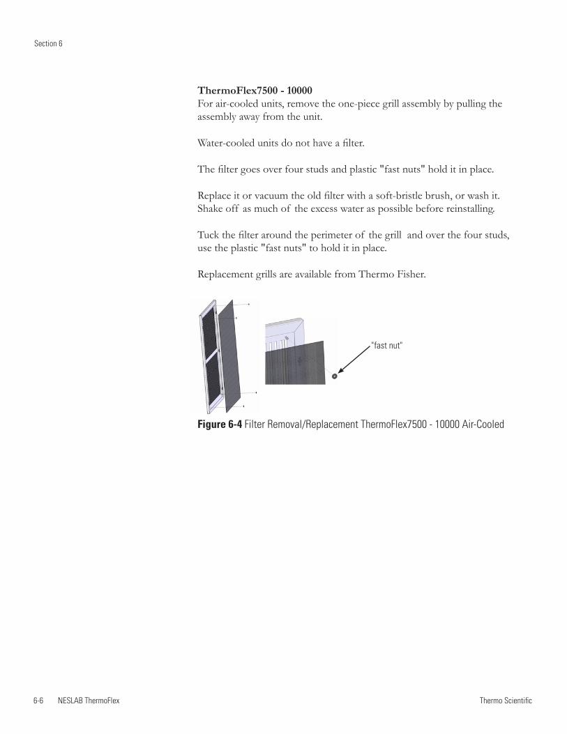
6-6 NESLAB ThermoFlex
Section 6
Thermo Scientific
ThermoFlex7500 - 10000 For air-cooled units, remove the one-piece grill assembly by pulling the assembly away from the unit.
Water-cooled units do not have a filter.
The filter goes over four studs and plastic "fast nuts" hold it in place.
Replace it or vacuum the old filter with a soft-bristle brush, or wash it. Shake off as much of the excess water as possible before reinstalling.
Tuck the filter around the perimeter of the grill and over the four studs, use the plastic "fast nuts" to hold it in place.
Replacement grills are available from Thermo Fisher.
Figure 6-4 Filter Removal/Replacement ThermoFlex7500 - 10000 Air-Cooled
"fast nut"
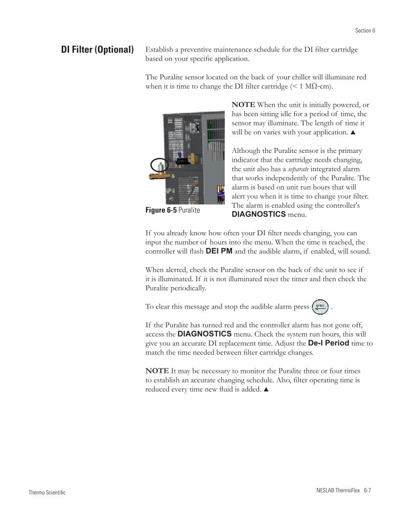
Section 6
NESLAB ThermoFlex 6-7 Thermo Scientific
DI Filter (Optional) Establish a preventive maintenance schedule for the DI filter cartridge based on your specific application.
The Puralite sensor located on the back of your chiller will illuminate red when it is time to change the DI filter cartridge (< 1 MΩ-cm).
NOTE When the unit is initially powered, or has been sitting idle for a period of time, the sensor may illuminate. The length of time it will be on varies with your application.
Although the Puralite sensor is the primary indicator that the cartridge needs changing, the unit also has a separate integrated alarm that works independently of the Puralite. The alarm is based on unit run hours that will alert you when it is time to change your filter. The alarm is enabled using the controller's DIAGNOSTICS menu.
If you already know how often your DI filter needs changing, you can input the number of hours into the menu. When the time is reached, the controller will flash DEI PM and the audible alarm, if enabled, will sound.
When alerted, check the Puralite sensor on the back of the unit to see if it is illuminated. If it is not illuminated reset the timer and then check the Puralite periodically.
To clear this message and stop the audible alarm press .
If the Puralite has turned red and the controller alarm has not gone off, access the DIAGNOSTICS menu. Check the system run hours, this will give you an accurate DI replacement time. Adjust the De-I Period time to match the time needed between filter cartridge changes.
NOTE It may be necessary to monitor the Puralite three or four times to establish an accurate changing schedule. Also, filter operating time is reduced every time new fluid is added.
Figure 6-5 Puralite
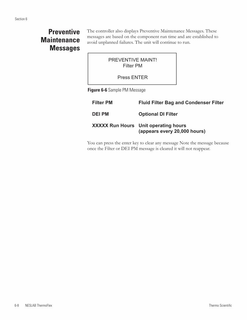
6-8 NESLAB ThermoFlex
Section 6
Thermo Scientific
Figure 6-6 Sample PM Message
Preventive Maintenance
Messages
The controller also displays Preventive Maintenance Messages. These messages are based on the component run time and are established to avoid unplanned failures. The unit will continue to run.
Filter PM Fluid Filter Bag and Condenser Filter
DEI PM Optional DI Filter
XXXXX Run Hours Unit operating hours (appears every 20,000 hours)
You can press the enter key to clear any message Note the message because once the Filter or DEI PM message is cleared it will not reappear.
PREVENTIVE MAINT!Filter PM
Press ENTER
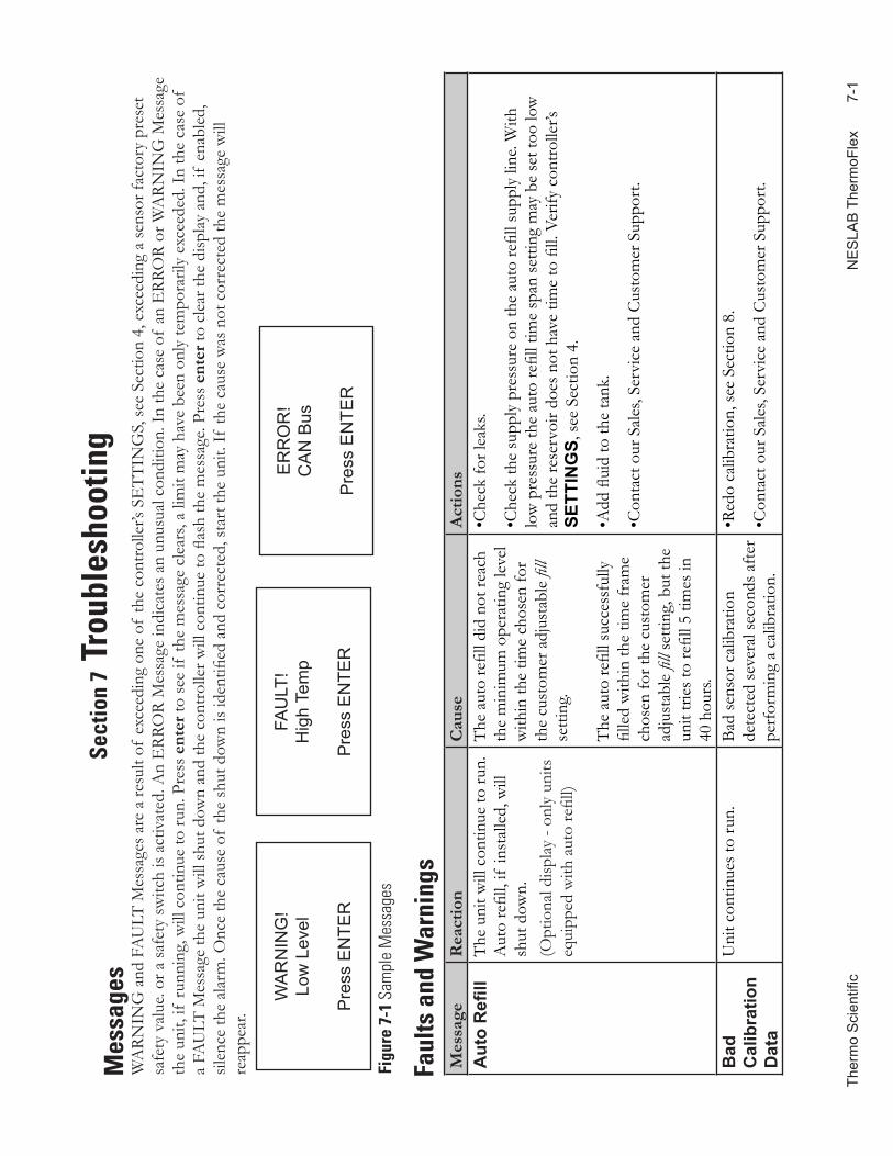
Ther
mo
Sci
entifi
c
NE
SLA
B T
herm
oFle
x
7-
1
Mes
sage
s
Faul
ts a
nd W
arni
ngs
Sect
ion
7 Tr
oubl
esho
otin
gW
ARN
ING
and
FA
ULT
Mes
sage
s are
a re
sult
of e
xcee
ding
one
of
the
cont
rolle
r’s S
ETT
ING
S, se
e Se
ctio
n 4,
exc
eedi
ng a
sens
or fa
ctor
y pr
eset
sa
fety
val
ue. o
r a sa
fety
switc
h is
activ
ated
. An
ERR
OR
Mes
sage
indi
cate
s an
unus
ual c
ondi
tion.
In th
e ca
se o
f an
ERR
OR
or W
ARN
ING
Mes
sage
th
e un
it, if
runn
ing,
will
con
tinue
to ru
n. P
ress
ent
er to
see
if th
e m
essa
ge c
lear
s, a
limit
may
hav
e be
en o
nly
tem
pora
rily
exce
eded
. In
the
case
of
a FA
ULT
Mes
sage
the
unit
will
shut
dow
n an
d th
e co
ntro
ller w
ill c
ontin
ue to
flas
h th
e m
essa
ge. P
ress
ent
er to
cle
ar th
e di
splay
and
, if
enab
led,
sil
ence
the
alar
m. O
nce
the
caus
e of
the
shut
dow
n is
iden
tified
and
cor
rect
ed, s
tart
the
unit.
If th
e ca
use
was
not
cor
rect
ed th
e m
essa
ge w
ill
reap
pear
.
Figu
re 7
-1 S
ampl
e M
essa
ges
ER
RO
R!
CA
N B
us
Pre
ss E
NTE
R
WA
RN
ING
!Lo
w L
evel
Pre
ss E
NTE
R
FAU
LT!
Hig
h Te
mp
Pre
ss E
NTE
R
Mes
sage
Rea
ctio
nC
ause
Act
ions
Aut
o R
efill
The
uni
t will
con
tinue
to ru
n.
Aut
o re
fill,
if in
stal
led,
will
sh
ut d
own.
(Opt
iona
l disp
lay -
only
uni
ts
equi
pped
with
aut
o re
fill)
The
aut
o re
fill d
id n
ot re
ach
the
min
imum
ope
ratin
g le
vel
with
in th
e tim
e ch
osen
for
the
cust
omer
adj
usta
ble
fill
setti
ng.
The
aut
o re
fill s
ucce
ssfu
lly
fille
d w
ithin
the
time
fram
e ch
osen
for t
he c
usto
mer
ad
just
able
fill
setti
ng, b
ut th
e un
it tri
es to
refil
l 5 ti
mes
in
40 h
ours
.
•Che
ck fo
r lea
ks.
•Che
ck th
e su
pply
pre
ssur
e on
the
auto
refil
l sup
ply
line.
With
lo
w p
ress
ure
the
auto
refil
l tim
e sp
an se
tting
may
be
set t
oo lo
w
and
the
rese
rvoi
r doe
s not
hav
e tim
e to
fill.
Ver
ify c
ontro
ller’s
SE
TTIN
GS,
see
Sect
ion
4.
•Add
flui
d to
the
tank
.
•Con
tact
our
Sal
es, S
ervi
ce a
nd C
usto
mer
Sup
port
.
Bad
C
alib
ratio
n
Dat
a
Uni
t con
tinue
s to
run.
Bad
sens
or c
alib
ratio
n de
tect
ed se
vera
l sec
onds
afte
r pe
rfor
min
g a
calib
ratio
n.
•Red
o ca
libra
tion,
see
Sect
ion
8.
•Con
tact
our
Sal
es, S
ervi
ce a
nd C
usto
mer
Sup
port
.
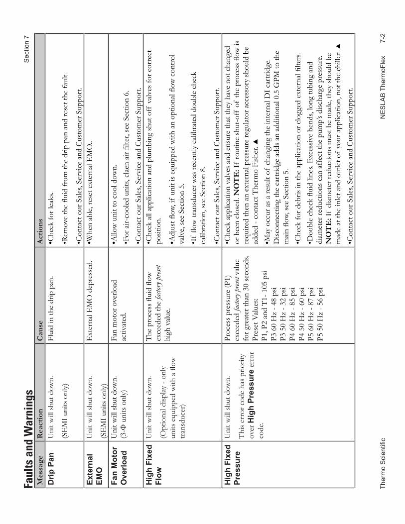
Ther
mo
Sci
entifi
c
NE
SLA
B T
herm
oFle
x
7-
2
S
ectio
n 7
Mes
sage
Rea
ctio
nC
ause
Act
ions
Drip
Pan
Uni
t will
shut
dow
n.
(SE
MI u
nits
onl
y)
Flui
d in
the
drip
pan
.•C
heck
for l
eaks
.
•Rem
ove
the
fluid
from
the
drip
pan
and
rese
t the
faul
t.
•Con
tact
our
Sal
es, S
ervi
ce a
nd C
usto
mer
Sup
port
.Ex
tern
al
EMO
Uni
t will
shut
dow
n.
(SE
MI u
nits
onl
y)
Ext
erna
l EM
O d
epre
ssed
.•W
hen
able
, res
et e
xter
nal E
MO
..
Fan
Mot
or
Ove
rload
Uni
t will
shut
dow
n.(3
-Ф u
nits
onl
y)Fa
n m
otor
ove
rload
ac
tivat
ed.
•Allo
w u
nit t
o co
ol d
own.
•For
air-
cool
ed u
nits,
cla
en a
ir fil
ter,
see
Sect
ion
6.•C
onta
ct o
ur S
ales
, Ser
vice
and
Cus
tom
er S
uppo
rt.
Hig
h Fi
xed
Flow
Uni
t will
shut
dow
n.
(Opt
iona
l disp
lay -
only
un
its e
quip
ped
with
a fl
ow
trans
duce
r)
The
pro
cess
flui
d flo
w
exce
eded
the
factor
y pres
et
high
val
ue.
•Che
ck a
ll ap
plic
atio
n an
d pl
umbi
ng sh
ut o
ff v
alve
s for
cor
rect
po
sitio
n.
•Adj
ust fl
ow, i
f un
it is
equi
pped
with
an
optio
nal fl
ow c
ontro
l va
lve,
see
Sect
ion
5.•I
f flo
w tr
ansd
ucer
was
rece
ntly
cal
ibra
ted
doub
le c
heck
ca
libra
tion,
see
Sect
ion
8.
•Con
tact
our
Sal
es, S
ervi
ce a
nd C
usto
mer
Sup
port
.H
igh
Fixe
d Pr
essu
reU
nit w
ill sh
ut d
own.
Thi
s err
or c
ode
has p
riorit
y ov
er H
igh
Pres
sure
err
or
code
.
Proc
ess p
ress
ure
(P1)
ex
ceed
ed fa
ctory
pres
et va
lue
for g
reat
er th
an 3
0 se
cond
s. Pr
eset
Val
ues:
P1, P
2 an
d T1
- 105
psi
P3 6
0 H
z - 4
8 ps
i P3
50
Hz
- 32
psi
P4 6
0 H
z - 8
5 ps
i P4
50
Hz
- 60
psi
P5 6
0 H
z - 8
7 ps
i P5
50
Hz
- 56
psi
•Che
ck a
pplic
atio
n va
lves
and
ens
ure
that
they
hav
e no
t cha
nged
or
bee
n cl
osed
. NO
TE
: If
rout
ine
shut
-off
of
the
proc
ess fl
ow is
re
quire
d th
en a
n ex
tern
al p
ress
ure
regu
lato
r acc
esso
ry sh
ould
be
adde
d - c
onta
ct T
herm
o Fi
sher
. •M
ay o
ccur
as a
resu
lt of
cha
ngin
g th
e in
tern
al D
I car
tridg
e. D
iscon
nect
ing
the
cart
ridge
add
s an
addi
tiona
l 0.5
GPM
to th
e m
ain
flow,
see
Sect
ion
5.•C
heck
for d
ebris
in th
e ap
plic
atio
n or
clo
gged
ext
erna
l filte
rs.
•Dou
ble
chec
k flu
id li
nes.
Exc
essiv
e be
nds,
long
tubi
ng a
nd
diam
eter
redu
ctio
ns c
an a
ffec
t the
pum
p’s d
ischa
rge
pres
sure
. N
OT
E: I
f di
amet
er re
duct
ions
mus
t be
mad
e, th
ey sh
ould
be
mad
e at
the
inle
t and
out
let o
f yo
ur a
pplic
atio
n, n
ot th
e ch
iller
. •C
onta
ct o
ur S
ales
, Ser
vice
and
Cus
tom
er S
uppo
rt.
Faul
ts a
nd W
arni
ngs
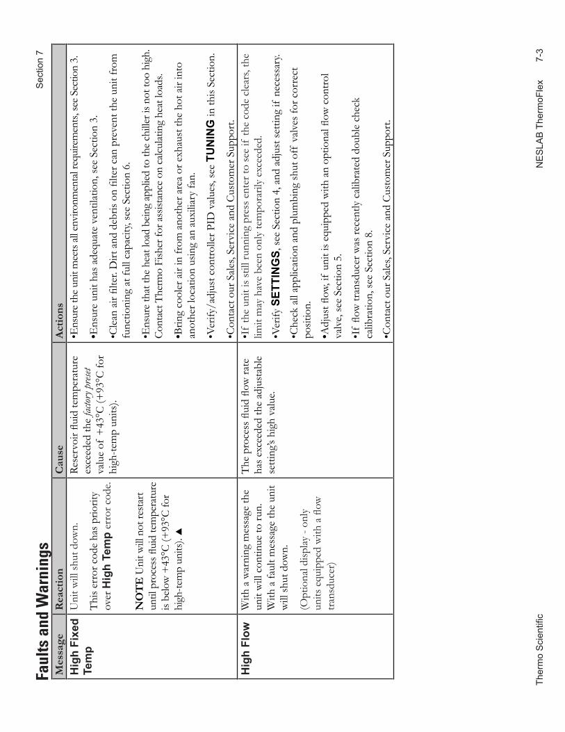
Ther
mo
Sci
entifi
c
NE
SLA
B T
herm
oFle
x
7-
3
Sec
tion
7
Mes
sage
Rea
ctio
nC
ause
Act
ions
Hig
h Fi
xed
Tem
pU
nit w
ill sh
ut d
own.
Thi
s err
or c
ode
has p
riorit
y ov
er H
igh
Tem
p er
ror c
ode.
NO
TE
Uni
t will
not
rest
art
until
pro
cess
flui
d te
mpe
ratu
re
is be
low
+43
°C (+
93°C
for
high
-tem
p un
its).
Rese
rvoi
r flui
d te
mpe
ratu
re
exce
eded
the
factor
y pres
et va
lue
of +
43°C
(+93
°C fo
r hi
gh-te
mp
units
).
•Ens
ure t
he u
nit m
eets
all en
viro
nmen
tal r
equi
rem
ents,
see S
ectio
n 3.
•Ens
ure
unit
has a
dequ
ate
vent
ilatio
n, se
e Se
ctio
n 3.
•Cle
an a
ir fil
ter.
Dirt
and
deb
ris o
n fil
ter c
an p
reve
nt th
e un
it fr
om
func
tioni
ng a
t ful
l cap
acity
, see
Sec
tion
6.
•Ens
ure
that
the
heat
load
bein
g ap
plied
to th
e ch
iller
is n
ot to
o hi
gh.
Cont
act T
herm
o Fi
sher
for a
ssist
ance
on
calcu
latin
g he
at lo
ads.
•Brin
g co
oler
air
in fr
om a
noth
er a
rea
or e
xhau
st th
e ho
t air
into
an
othe
r loc
atio
n us
ing
an a
uxili
ary
fan.
•Ver
ify/a
djus
t con
trolle
r PID
val
ues,
see
TUN
ING
in th
is Se
ctio
n.
•Con
tact
our
Sal
es, S
ervi
ce a
nd C
usto
mer
Sup
port
.H
igh
Flow
With
a w
arni
ng m
essa
ge th
e un
it w
ill c
ontin
ue to
run.
W
ith a
faul
t mes
sage
the
unit
will
shut
dow
n.
(Opt
iona
l disp
lay -
only
un
its e
quip
ped
with
a fl
ow
trans
duce
r)
The
pro
cess
flui
d flo
w ra
te
has e
xcee
ded
the
adju
stab
le
setti
ng’s
high
val
ue.
•If
the
unit
is st
ill ru
nnin
g pr
ess e
nter
to se
e if
the
code
cle
ars,
the
limit
may
hav
e be
en o
nly
tem
pora
rily
exce
eded
.
•Ver
ify S
ETTI
NG
S, se
e Se
ctio
n 4,
and
adj
ust s
ettin
g if
nec
essa
ry.
•Che
ck a
ll ap
plic
atio
n an
d pl
umbi
ng sh
ut o
ff v
alve
s for
cor
rect
po
sitio
n.
•Adj
ust fl
ow, i
f un
it is
equi
pped
with
an
optio
nal fl
ow c
ontro
l va
lve,
see
Sect
ion
5.
•If
flow
tran
sduc
er w
as re
cent
ly c
alib
rate
d do
uble
che
ck
calib
ratio
n, se
e Se
ctio
n 8.
•Con
tact
our
Sal
es, S
ervi
ce a
nd C
usto
mer
Sup
port
.
Faul
ts a
nd W
arni
ngs
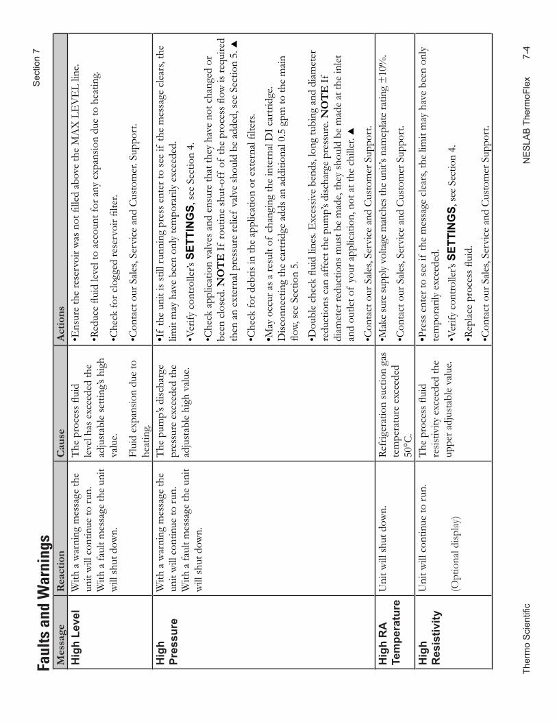
Ther
mo
Sci
entifi
c
NE
SLA
B T
herm
oFle
x
7-
4
S
ectio
n 7
Mes
sage
Rea
ctio
nC
ause
Act
ions
Hig
h Le
vel
With
a w
arni
ng m
essa
ge th
e un
it w
ill c
ontin
ue to
run.
W
ith a
faul
t mes
sage
the
unit
will
shut
dow
n.
The
pro
cess
flui
d le
vel h
as e
xcee
ded
the
adju
stab
le se
tting
’s hi
gh
valu
e.
Flui
d ex
pans
ion
due
to
heat
ing.
•Ens
ure
the
rese
rvoi
r was
not
fille
d ab
ove
the
MA
X L
EV
EL
line.
•Red
uce
fluid
leve
l to
acco
unt f
or a
ny e
xpan
sion
due
to h
eatin
g.
•Che
ck fo
r clo
gged
rese
rvoi
r filte
r.
•Con
tact
our
Sal
es, S
ervi
ce a
nd C
usto
mer
. Sup
port
.
Hig
h
Pres
sure
With
a w
arni
ng m
essa
ge th
e un
it w
ill c
ontin
ue to
run.
W
ith a
faul
t mes
sage
the
unit
will
shut
dow
n.
The
pum
p’s d
ischa
rge
pres
sure
exc
eede
d th
e ad
just
able
hig
h va
lue.
•If
the
unit
is st
ill ru
nnin
g pr
ess e
nter
to se
e if
the
mes
sage
cle
ars,
the
limit
may
hav
e be
en o
nly
tem
pora
rily
exce
eded
.
•Ver
ify c
ontro
ller’s
SET
TIN
GS,
see
Sect
ion
4.
•Che
ck a
pplic
atio
n va
lves
and
ens
ure
that
they
hav
e no
t cha
nged
or
been
clo
sed.
NO
TE
If ro
utin
e sh
ut-o
ff o
f th
e pr
oces
s flow
is re
quire
d th
en a
n ex
tern
al p
ress
ure
relie
f va
lve
shou
ld b
e ad
ded,
see
Sect
ion
5.
•Che
ck fo
r deb
ris in
the
appl
icat
ion
or e
xter
nal fi
lters
.
•May
occ
ur a
s a re
sult
of c
hang
ing
the
inte
rnal
DI c
artri
dge.
Disc
onne
ctin
g th
e ca
rtrid
ge a
dds a
n ad
ditio
nal 0
.5 g
pm to
the
mai
n flo
w, se
e Se
ctio
n 5.
•Dou
ble
chec
k flu
id li
nes.
Exc
essiv
e be
nds,
long
tubi
ng a
nd d
iam
eter
re
duct
ions
can
aff
ect t
he p
ump’
s disc
harg
e pr
essu
re. N
OT
E If
di
amet
er re
duct
ions
mus
t be
mad
e, th
ey sh
ould
be
mad
e at
the
inle
t an
d ou
tlet o
f yo
ur a
pplic
atio
n, n
ot a
t the
chi
ller.
•Con
tact
our
Sal
es, S
ervi
ce a
nd C
usto
mer
Sup
port
.H
igh
RA
Tem
pera
ture
Uni
t will
shut
dow
n.Re
frig
erat
ion
suct
ion
gas
tem
pera
ture
exc
eede
d 50
°C.
•Mak
e su
re su
pply
volta
ge m
atch
es th
e un
it’s n
amep
late
ratin
g ±
10%
.
•Con
tact
our
Sal
es, S
ervi
ce a
nd C
usto
mer
Sup
port
.
Hig
h
Res
istiv
ityU
nit w
ill c
ontin
ue to
run.
(Opt
iona
l disp
lay)
The
pro
cess
flui
d re
sistiv
ity e
xcee
ded
the
uppe
r adj
usta
ble
valu
e.
•Pre
ss e
nter
to se
e if
the
mes
sage
cle
ars,
the
limit
may
hav
e be
en o
nly
tem
pora
rily
exce
eded
. •V
erify
con
trolle
r’s S
ETTI
NG
S, se
e Se
ctio
n 4.
•R
epla
ce p
roce
ss fl
uid.
•Con
tact
our
Sal
es, S
ervi
ce a
nd C
usto
mer
Sup
port
.
Faul
ts a
nd W
arni
ngs
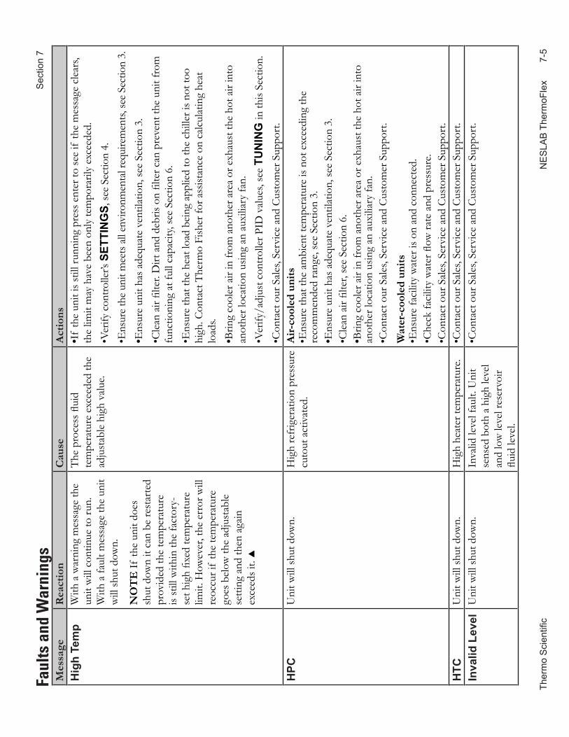
Ther
mo
Sci
entifi
c
NE
SLA
B T
herm
oFle
x
7-
5
Sec
tion
7
Mes
sage
Rea
ctio
nC
ause
Act
ions
Hig
h Te
mp
With
a w
arni
ng m
essa
ge th
e un
it w
ill c
ontin
ue to
run.
W
ith a
faul
t mes
sage
the
unit
will
shut
dow
n.
NO
TE
If th
e un
it do
es
shut
dow
n it
can
be re
star
ted
prov
ided
the
tem
pera
ture
is
still
with
in th
e fa
ctor
y-se
t hig
h fix
ed te
mpe
ratu
re
limit.
How
ever
, the
err
or w
ill
reoc
cur i
f th
e te
mpe
ratu
re
goes
bel
ow th
e ad
just
able
se
tting
and
then
aga
in
exce
eds i
t.
The
pro
cess
flui
d te
mpe
ratu
re e
xcee
ded
the
adju
stab
le h
igh
valu
e.
•If
the
unit
is st
ill ru
nnin
g pr
ess e
nter
to se
e if
the
mes
sage
cle
ars,
the
limit
may
hav
e be
en o
nly
tem
pora
rily
exce
eded
. •V
erify
con
trolle
r’s S
ETTI
NG
S, se
e Se
ctio
n 4.
•E
nsur
e th
e un
it m
eets
all
envi
ronm
enta
l req
uire
men
ts, se
e Se
ctio
n 3.
•Ens
ure
unit
has a
dequ
ate
vent
ilatio
n, se
e Se
ctio
n 3.
•Cle
an a
ir fil
ter.
Dirt
and
deb
ris o
n fil
ter c
an p
reve
nt th
e un
it fr
om
func
tioni
ng a
t ful
l cap
acity
, see
Sec
tion
6.•E
nsur
e th
at th
e he
at lo
ad b
eing
app
lied
to th
e ch
iller
is n
ot to
o hi
gh. C
onta
ct T
herm
o Fi
sher
for a
ssist
ance
on
calc
ulat
ing
heat
lo
ads.
•Brin
g co
oler
air
in fr
om a
noth
er a
rea
or e
xhau
st th
e ho
t air
into
an
othe
r loc
atio
n us
ing
an a
uxili
ary
fan.
•Ver
ify/a
djus
t con
trolle
r PID
val
ues,
see
TUN
ING
in th
is Se
ctio
n.
•Con
tact
our
Sal
es, S
ervi
ce a
nd C
usto
mer
Sup
port
.H
PCU
nit w
ill sh
ut d
own.
Hig
h re
frig
erat
ion
pres
sure
cu
tout
act
ivat
ed.
Air-
cool
ed u
nits
•Ens
ure
that
the
ambi
ent t
empe
ratu
re is
not
exc
eedi
ng th
e re
com
men
ded
rang
e, se
e Se
ctio
n 3.
•Ens
ure
unit
has a
dequ
ate
vent
ilatio
n, se
e Se
ctio
n 3.
•Cle
an a
ir fil
ter,
see
Sect
ion
6.•B
ring
cool
er a
ir in
from
ano
ther
are
a or
exh
aust
the
hot a
ir in
to
anot
her l
ocat
ion
usin
g an
aux
iliar
y fa
n.•C
onta
ct o
ur S
ales
, Ser
vice
and
Cus
tom
er S
uppo
rt.
Wat
er-c
oole
d un
its•E
nsur
e fa
cilit
y w
ater
is o
n an
d co
nnec
ted.
•Che
ck fa
cilit
y w
ater
flow
rate
and
pre
ssur
e.•C
onta
ct o
ur S
ales
, Ser
vice
and
Cus
tom
er S
uppo
rt.
HTC
Uni
t will
shut
dow
n.H
igh
heat
er te
mpe
ratu
re.
•Con
tact
our
Sal
es, S
ervi
ce a
nd C
usto
mer
Sup
port
.In
valid
Lev
elU
nit w
ill sh
ut d
own.
Inva
lid le
vel f
ault.
Uni
t se
nsed
bot
h a
high
leve
l an
d lo
w le
vel r
eser
voir
fluid
leve
l.
•Con
tact
our
Sal
es, S
ervi
ce a
nd C
usto
mer
Sup
port
.
Faul
ts a
nd W
arni
ngs
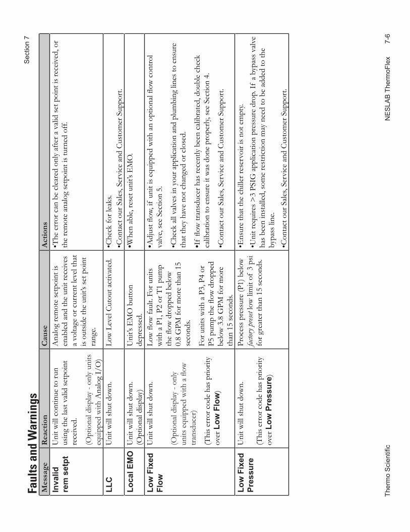
Ther
mo
Sci
entifi
c
NE
SLA
B T
herm
oFle
x
7-
6
S
ectio
n 7
Mes
sage
Rea
ctio
nC
ause
Act
ions
Inva
lid
rem
set
ptU
nit w
ill c
ontin
ue to
run
usin
g th
e la
st v
alid
setp
oint
re
ceiv
ed.
(Opt
iona
l disp
lay -
only
uni
ts
equi
pped
with
Ana
log
I/O
)
Ana
log
rem
ote
setp
oint
is
enab
led
and
the
unit
rece
ives
a
volta
ge o
r cur
rent
leve
l tha
t is
outs
ide
the
unit’
s set
poi
nt
rang
e.
•The
err
or c
an b
e cl
eare
d on
ly a
fter a
val
id se
t poi
nt is
rece
ived
, or
the
rem
ote
anal
og se
tpoi
nt is
turn
ed o
ff.
LLC
Uni
t will
shut
dow
n.Lo
w L
evel
Cut
out a
ctiv
ated
.•C
heck
for l
eaks
.•C
onta
ct o
ur S
ales
, Ser
vice
and
Cus
tom
er S
uppo
rt.
Loca
l EM
OU
nit w
ill sh
ut d
own.
(Opt
iona
l disp
lay)
Uni
t’s E
MO
but
ton
depr
esse
d.•W
hen
able
, res
et u
nit’s
EM
O.
Low
Fix
ed
Flow
Uni
t will
shut
dow
n.
(Opt
iona
l disp
lay -
only
un
its e
quip
ped
with
a fl
ow
trans
duce
r)
(Thi
s err
or c
ode
has p
riorit
y ov
er L
ow F
low
)
Low
flow
faul
t. Fo
r uni
ts
with
a P
1, P
2 or
T1
pum
p th
e flo
w d
ropp
ed b
elow
0.
8 G
PM fo
r mor
e th
an 1
5 se
cond
s.
For u
nits
with
a P
3, P
4 or
P5
pum
p th
e flo
w d
ropp
ed
belo
w 3
.8 G
PM fo
r mor
e th
an 1
5 se
cond
s.
•Adj
ust fl
ow, i
f un
it is
equi
pped
with
an
optio
nal fl
ow c
ontro
l va
lve,
see
Sect
ion
5.
•Che
ck a
ll va
lves
in y
our a
pplic
atio
n an
d pl
umbi
ng li
nes t
o en
sure
th
at th
ey h
ave
not c
hang
ed o
r clo
sed.
•If
flow
tran
sduc
er h
as re
cent
ly b
een
calib
rate
d, d
oubl
e ch
eck
calib
ratio
n to
ens
ure
it w
as d
one
prop
erly,
see
Sect
ion
4.
•Con
tact
our
Sal
es, S
ervi
ce a
nd C
usto
mer
Sup
port
.
Low
Fix
ed
Pres
sure
Uni
t will
shut
dow
n.
(Thi
s err
or c
ode
has p
riorit
y ov
er L
ow P
ress
ure)
Proc
ess p
ress
ure
(P1)
bel
ow
factor
y pres
et lo
w li
mit
of 3
psi
for g
reat
er th
an 1
5 se
cond
s.
•Ens
ure
that
the
chill
er re
serv
oir i
s not
em
pty.
•Uni
t req
uire
s >3
PSIG
app
licat
ion
pres
sure
dro
p. If
a b
ypas
s val
ve
has b
een
inst
alle
d, so
me
rest
rictio
n m
ay n
eed
to b
e ad
ded
to th
e by
pass
line
.•C
onta
ct o
ur S
ales
, Ser
vice
and
Cus
tom
er S
uppo
rt.
Faul
ts a
nd W
arni
ngs
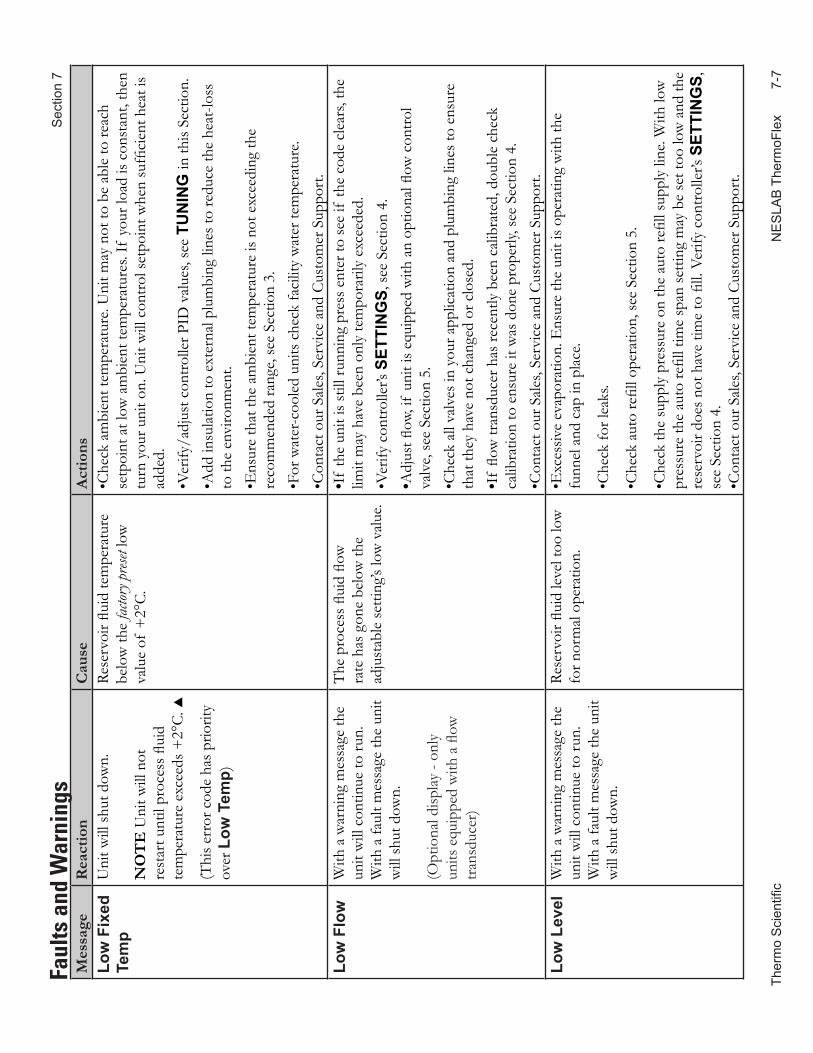
Ther
mo
Sci
entifi
c
NE
SLA
B T
herm
oFle
x
7-
7
Sec
tion
7
Mes
sage
Rea
ctio
nC
ause
Act
ions
Low
Fix
ed
Tem
pU
nit w
ill sh
ut d
own.
NO
TE
Uni
t will
not
re
star
t unt
il pr
oces
s flui
d te
mpe
ratu
re e
xcee
ds +
2°C.
(Thi
s err
or c
ode
has p
riorit
y ov
er L
ow T
emp)
Rese
rvoi
r flui
d te
mpe
ratu
re
belo
w th
e fac
tory p
reset
low
va
lue
of +
2°C.
•Che
ck a
mbi
ent t
empe
ratu
re. U
nit m
ay n
ot to
be
able
to re
ach
setp
oint
at l
ow a
mbi
ent t
empe
ratu
res.
If y
our l
oad
is co
nsta
nt, t
hen
turn
you
r uni
t on.
Uni
t will
con
trol s
etpo
int w
hen
suffi
cien
t hea
t is
adde
d.
•Ver
ify/a
djus
t con
trolle
r PID
val
ues,
see
TUN
ING
in th
is Se
ctio
n.
•Add
insu
latio
n to
ext
erna
l plu
mbi
ng li
nes t
o re
duce
the
heat
-loss
to
the
envi
ronm
ent.
•Ens
ure
that
the
ambi
ent t
empe
ratu
re is
not
exc
eedi
ng th
e re
com
men
ded
rang
e, se
e Se
ctio
n 3.
•For
wat
er-c
oole
d un
its c
heck
faci
lity
wat
er te
mpe
ratu
re.
•Con
tact
our
Sal
es, S
ervi
ce a
nd C
usto
mer
Sup
port
.Lo
w F
low
With
a w
arni
ng m
essa
ge th
e un
it w
ill c
ontin
ue to
run.
W
ith a
faul
t mes
sage
the
unit
will
shut
dow
n.
(Opt
iona
l disp
lay -
only
un
its e
quip
ped
with
a fl
ow
trans
duce
r)
The
pro
cess
flui
d flo
w
rate
has
gon
e be
low
the
adju
stab
le se
tting
’s lo
w v
alue
.
•If
the
unit
is st
ill ru
nnin
g pr
ess e
nter
to se
e if
the
code
cle
ars,
the
limit
may
hav
e be
en o
nly
tem
pora
rily
exce
eded
. •V
erify
con
trolle
r’s S
ETTI
NG
S, se
e Se
ctio
n 4.
•Adj
ust fl
ow, i
f un
it is
equi
pped
with
an
optio
nal fl
ow c
ontro
l va
lve,
see
Sect
ion
5.•C
heck
all
valv
es in
you
r app
licat
ion
and
plum
bing
line
s to
ensu
re
that
they
hav
e no
t cha
nged
or c
lose
d.
•If
flow
tran
sduc
er h
as re
cent
ly b
een
calib
rate
d, d
oubl
e ch
eck
calib
ratio
n to
ens
ure
it w
as d
one
prop
erly,
see
Sect
ion
4.•C
onta
ct o
ur S
ales
, Ser
vice
and
Cus
tom
er S
uppo
rt.
Low
Lev
elW
ith a
war
ning
mes
sage
the
unit
will
con
tinue
to ru
n.
With
a fa
ult m
essa
ge th
e un
it w
ill sh
ut d
own.
Rese
rvoi
r flui
d le
vel t
oo lo
w
for n
orm
al o
pera
tion.
•Exc
essiv
e ev
apor
atio
n. E
nsur
e th
e un
it is
oper
atin
g w
ith th
e fu
nnel
and
cap
in p
lace
.
•Che
ck fo
r lea
ks.
•Che
ck a
uto
refil
l ope
ratio
n, se
e Se
ctio
n 5.
•Che
ck th
e su
pply
pre
ssur
e on
the
auto
refil
l sup
ply
line.
With
low
pr
essu
re th
e au
to re
fill t
ime
span
setti
ng m
ay b
e se
t too
low
and
the
rese
rvoi
r doe
s not
hav
e tim
e to
fill.
Ver
ify c
ontro
ller’s
SET
TIN
GS,
se
e Se
ctio
n 4.
•Con
tact
our
Sal
es, S
ervi
ce a
nd C
usto
mer
Sup
port
.
Faul
ts a
nd W
arni
ngs
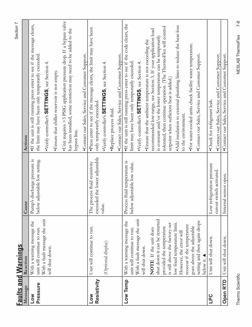
Ther
mo
Sci
entifi
c
NE
SLA
B T
herm
oFle
x
7-
8
S
ectio
n 7
Mes
sage
Rea
ctio
nC
ause
Act
ions
Low
Pr
essu
reW
ith a
war
ning
mes
sage
the
unit
will
con
tinue
to ru
n.
With
a fa
ult m
essa
ge th
e un
it w
ill sh
ut d
own.
Pum
p’s d
ischa
rge
pres
sure
is
belo
w a
djus
tabl
e lo
w se
tting
.•I
f th
e un
it is
still
runn
ing
pres
s ent
er to
see
if th
e m
essa
ge c
lear
s, th
e lim
it m
ay h
ave
been
onl
y te
mpo
raril
y ex
ceed
ed.
•Ver
ify c
ontro
ller’s
SET
TIN
GS,
see
Sect
ion
4.
•Ens
ure
that
chi
ller r
eser
voir
is no
t em
pty.
•Uni
t req
uire
s >3
PSIG
app
licat
ion
pres
sure
dro
p. If
a b
ypas
s val
ve
has b
een
inst
alle
d, so
me
rest
rictio
n m
ay n
eed
to b
e ad
ded
to th
e by
pass
line
.
•Con
tact
our
Sal
es, S
ervi
ce a
nd C
usto
mer
Sup
port
.Lo
w
Res
istiv
ityU
nit w
ill c
ontin
ue to
run.
(Opt
iona
l disp
lay)
The
pro
cess
flui
d re
sistiv
ity
exce
eded
the
low
er a
djus
tabl
e va
lue.
•Pre
ss e
nter
to se
e if
the
mes
sage
cle
ars,
the
limit
may
hav
e be
en
only
tem
pora
rily
exce
eded
. •V
erify
con
trolle
r’s S
ETTI
NG
S, se
e Se
ctio
n 4.
•R
epla
ce p
roce
ss fl
uid.
•Con
tact
our
Sal
es, S
ervi
ce a
nd C
usto
mer
Sup
port
.Lo
w T
emp
With
a w
arni
ng m
essa
ge th
e un
it w
ill c
ontin
ue to
run.
W
ith a
faul
t mes
sage
the
unit
will
shut
dow
n.
NO
TE
If
the
unit
does
sh
ut d
own
it ca
n be
rest
arte
d pr
ovid
ed th
e te
mpe
ratu
re
is st
ill a
bove
the
fact
ory-
set
low
fixe
d te
mpe
ratu
re li
mit.
H
owev
er, t
he e
rror
will
re
occu
r if
the
tem
pera
ture
go
es a
bove
the
adju
stab
le
setti
ng a
nd th
en a
gain
dro
ps
belo
w it
.
Proc
ess fl
uid
tem
pera
ture
is
belo
w a
djus
tabl
e lo
w v
alue
.•I
f th
e un
it is
still
runn
ing
pres
s ent
er to
see
if th
e co
de c
lear
s, th
e lim
it m
ay h
ave
been
onl
y te
mpo
raril
y ex
ceed
ed.
•Ver
ify c
ontro
ller’s
SET
TIN
GS,
see
Sect
ion
4.•E
nsur
e th
at th
e am
bien
t tem
pera
ture
is n
ot e
xcee
ding
the
reco
mm
ende
d lo
w-r
ange
, see
Sec
tion
3. If
you
r app
licat
ion
load
is
cons
tant
and
/or t
he lo
wer
tem
pera
ture
can
be
tem
pora
rily
tole
rate
d, th
en c
ontin
ue o
pera
tion.
(The
The
rmoF
lex
will
con
trol
setp
oint
whe
n su
ffici
ent h
eat i
s add
ed.)
•Add
insu
latio
n to
ext
erna
l plu
mbi
ng li
nes t
o re
duce
the
heat
-loss
to
the
envi
ronm
ent.
•For
wat
er-c
oole
d un
its c
heck
faci
lity
wat
er te
mpe
ratu
re.
•Con
tact
our
Sal
es, S
ervi
ce a
nd C
usto
mer
Sup
port
.
LPC
Uni
t will
shut
dow
n.Lo
w re
frig
erat
ion
pres
sure
cu
tout
switc
h ac
tivat
ed.
•Che
ck fo
r ref
riger
ant l
eak.
•Con
tact
our
Sal
es, S
ervi
ce a
nd C
usto
mer
Sup
port
.O
pen
RTD
Uni
t will
shut
dow
n.In
tern
al se
nsor
ope
n.•C
onta
ct o
ur S
ales
, Ser
vice
and
Cus
tom
er S
uppo
rt.
Faul
ts a
nd W
arni
ngs
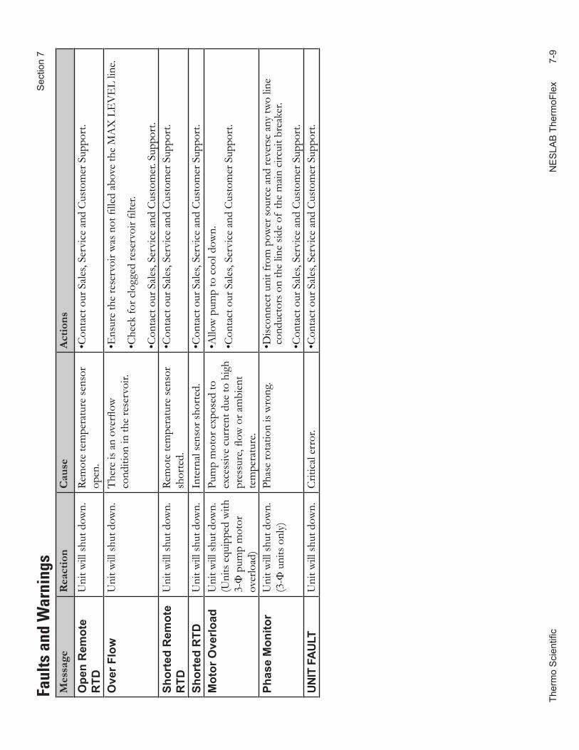
Ther
mo
Sci
entifi
c
NE
SLA
B T
herm
oFle
x
7-
9
Sec
tion
7 Fa
ults
and
War
ning
sM
essa
geR
eact
ion
Cau
seA
ctio
ns
Ope
n R
emot
e R
TDU
nit w
ill sh
ut d
own.
Rem
ote
tem
pera
ture
sens
or
open
.•C
onta
ct o
ur S
ales
, Ser
vice
and
Cus
tom
er S
uppo
rt.
Ove
r Flo
wU
nit w
ill sh
ut d
own.
The
re is
an
over
flow
co
nditi
on in
the
rese
rvoi
r.•E
nsur
e th
e re
serv
oir w
as n
ot fi
lled
abov
e th
e M
AX
LE
VE
L lin
e.
•Che
ck fo
r clo
gged
rese
rvoi
r filte
r.
•Con
tact
our
Sal
es, S
ervi
ce a
nd C
usto
mer
. Sup
port
.Sh
orte
d R
emot
e R
TDU
nit w
ill sh
ut d
own.
Rem
ote
tem
pera
ture
sens
or
shor
ted.
•Con
tact
our
Sal
es, S
ervi
ce a
nd C
usto
mer
Sup
port
.
Shor
ted
RTD
Uni
t will
shut
dow
n.In
tern
al se
nsor
shor
ted.
•Con
tact
our
Sal
es, S
ervi
ce a
nd C
usto
mer
Sup
port
.M
otor
Ove
rload
Uni
t will
shut
dow
n.(U
nits
equ
ippe
d w
ith
3-Ф
pum
p m
otor
ov
erlo
ad)
Pum
p m
otor
exp
osed
to
exce
ssiv
e cu
rren
t due
to h
igh
pres
sure
, flow
or a
mbi
ent
tem
pera
ture
.
•Allo
w p
ump
to c
ool d
own.
•Con
tact
our
Sal
es, S
ervi
ce a
nd C
usto
mer
Sup
port
.
Phas
e M
onito
rU
nit w
ill sh
ut d
own.
(3-Ф
uni
ts o
nly)
Phas
e ro
tatio
n is
wro
ng.
• Disc
onne
ct u
nit f
rom
pow
er so
urce
and
reve
rse
any
two
line
cond
ucto
rs o
n th
e lin
e sid
e of
the
mai
n ci
rcui
t bre
aker
.
•Con
tact
our
Sal
es, S
ervi
ce a
nd C
usto
mer
Sup
port
.UN
IT F
AULT
Uni
t will
shut
dow
n.C
ritic
al e
rror
.•C
onta
ct o
ur S
ales
, Ser
vice
and
Cus
tom
er S
uppo
rt.
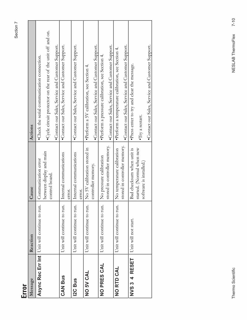
Ther
mo
Sci
entifi
c
NE
SLA
B T
herm
oFle
x
7-
10
S
ectio
n 7
Mes
sage
Rea
ctio
nC
ause
Act
ions
Asy
nc R
ec E
rr In
tU
nit w
ill c
ontin
ue to
run.
Com
mun
icat
ion
erro
r be
twee
n di
splay
and
mai
n co
ntro
l boa
rd.
•Che
ck th
e se
rial c
omm
unic
atio
n co
nnec
tion.
•Cyc
le c
ircui
t pro
tect
or o
n th
e re
ar o
f th
e un
it of
f an
d on
.
•Con
tact
our
Sal
es, S
ervi
ce a
nd C
usto
mer
Sup
port
.C
AN
Bus
Uni
t will
con
tinue
to ru
n.In
tern
al c
omm
unic
atio
ns
erro
r.•C
onta
ct o
ur S
ales
, Ser
vice
and
Cus
tom
er S
uppo
rt.
I2C
Bus
Uni
t will
con
tinue
to ru
n.In
tern
al c
omm
unic
atio
ns
erro
r.•C
onta
ct o
ur S
ales
, Ser
vice
and
Cus
tom
er S
uppo
rt.
NO
5V
CA
LU
nit w
ill c
ontin
ue to
run.
No
5V c
alib
ratio
n st
ored
in
cont
rolle
r mem
ory.
•Per
form
a 5
V c
alib
ratio
n, se
e Se
ctio
n 4.
•Con
tact
our
Sal
es, S
ervi
ce a
nd C
usto
mer
Sup
port
.N
O P
RES
CA
LU
nit w
ill c
ontin
ue to
run.
No
pres
sure
cal
ibra
tion
stor
ed in
con
trolle
r mem
ory.
•Per
form
a p
ress
ure
calib
ratio
n, se
e Se
ctio
n 4.
•Con
tact
our
Sal
es, S
ervi
ce a
nd C
usto
mer
Sup
port
.N
O R
TD C
AL
Uni
t will
con
tinue
to ru
n.N
o te
mpe
ratu
re c
alib
ratio
n st
ored
in c
ontro
ller m
emor
y.•P
erfo
rm a
tem
pera
ture
cal
ibra
tion,
see
Sect
ion
4.
•Con
tact
our
Sal
es, S
ervi
ce a
nd C
usto
mer
Sup
port
.N
VS 3
4 R
ESET
Uni
t will
not
star
t.Ba
d ch
ecks
um w
hen
unit
is st
arte
d. (N
orm
al w
hen
new
so
ftwar
e is
inst
alle
d.)
•Pre
ss e
nter
to tr
y an
d cl
ear t
he m
essa
ge.
•Try
a re
star
t.
•Con
tact
our
Sal
es, S
ervi
ce a
nd C
usto
mer
Sup
port
.
Erro
r
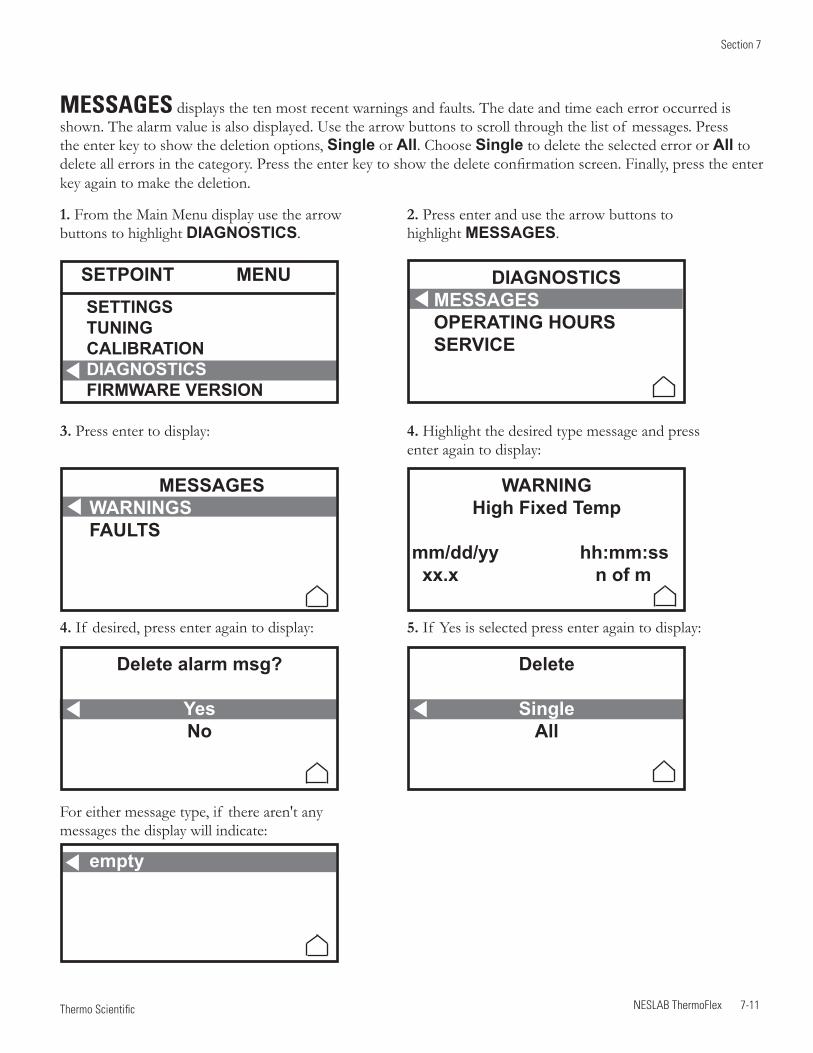
Section 7
NESLAB ThermoFlex 7-11 Thermo Scientific
MESSAGES displays the ten most recent warnings and faults. The date and time each error occurred is shown. The alarm value is also displayed. Use the arrow buttons to scroll through the list of messages. Press the enter key to show the deletion options, Single or All. Choose Single to delete the selected error or All to delete all errors in the category. Press the enter key to show the delete confirmation screen. Finally, press the enter key again to make the deletion.
1. From the Main Menu display use the arrow buttons to highlight DIAGNOSTICS.
2. Press enter and use the arrow buttons to highlight MESSAGES.
4. If desired, press enter again to display:
4. Highlight the desired type message and press enter again to display:
5. If Yes is selected press enter again to display:
For either message type, if there aren't any messages the display will indicate:
SETPOINT MENUSETTINGSTUNINGCALIBRATIONDIAGNOSTICS FIRMWARE VERSION
DIAGNOSTICSMESSAGESOPERATING HOURSSERVICE
WARNINGHigh Fixed Temp
mm/dd/yy hh:mm:ss xx.x n of m
3. Press enter to display:
MESSAGESWARNINGSFAULTS
Delete alarm msg?
YesNo
empty
Delete
SingleAll
Section 7
7-12 NESLAB ThermoFlex Thermo Scientific
Checklist Unit will not start
For first time use, please refer to the quick start instructions included with your unit or the copy in this manual. The manual's copy follows the Table of Contents.
Check the controller for messages, see Messages in this section.
Ensure the circuit protector is in the on ( I ) position.
For ThermoFlex900 - 5000 Global Voltage units ensure the unit is properly configured, see Appendix B.
Make sure supply voltage is connected and matches the unit's nameplate rating ±10%
NOTE Once RS232 or RS485 is activated, all keypad operations are disabled except for turning the unit off and changing the serial communication's settings.
Unit shuts down
Ensure button wasn't accidently pressed.
Ensure the circuit protector is in the on ( I ) position.
Check the controller for messages, see Messages in this section.
Make sure supply voltage is connected and matches the unit's nameplate rating ±10%.
Restart the unit.
Clearing Messages
Note the code in case it cleares before you are done troubleshooting.
If desired, silence the audible alarm by pressing enter.
If the unit shut down the controller will continue to display the message. Press enter to clear the display and silence any alarm. Refer to Messages in this section. Once the cause of the shut down is identified and corrected, start the unit. If the cause was not corrected the message will reappear.
If the unit is still running press enter to see if the message clears, a limit may have been only temporarily exceeded. If the message does not clear refer to Messages in this section.
Section 7
NESLAB ThermoFlex 7-13 Thermo Scientific
Unit will not circulate process fluid
Check the reservoir level. Fill, if necessary.
Ensure the reservoir bag filter is not clogged.
Check the application for restrictions in the cooling lines.
Unit requires >3 PSIG application pressure drop. If a bypass valve has been installed, a restriction may need to be added to the bypass line.
The pump motor overloaded. The pump's internal overtemperature overcurrent device will shut off the pump causing the flow to stop. This can be caused by low fluid, debris in system, operating unit in a high ambient temperature condition or excessively confined space. Allow time for the motor to cool down.
Make sure supply voltage matches the unit's nameplate rating ±10%.
Inadequate temperature control
Verify the setpoint.
Make sure the condenser/air filter is free of dust and debris.
Check the fluid concentration, see Section 3.
Ensure your unit's installation complies with the site requirements listed in Section 3.
Make sure supply voltage matches the unit's nameplate rating ±10%.
If the temperature continues to rise, make sure your application's heat load does not exceed the rated specifications.
Check for high thermal gradients (i.e., the application load is being turned on and off or rapidly changing).
If operating at high altitude note that heat removal capacity decreases 1.2% per 1,000 feet above sea level. Also, reduce the maximum temperature for the air entering the ThermoFlex by 1°C per 1,000 feet above sea level.
Verify/adjust controller PID values, see next page. Ensure the unit was shut down properly, see Section 4. If not the compressor may be damaged.
Unit vibration
The optional pressure relief valve setting may be the cause. If it is, change the pressure setting ± 5 psi to eliminate the vibration.
Please contact Thermo Fisher Scientific Sales Service and Customer Support if you need any additional information, see inside cover for contact instructions.
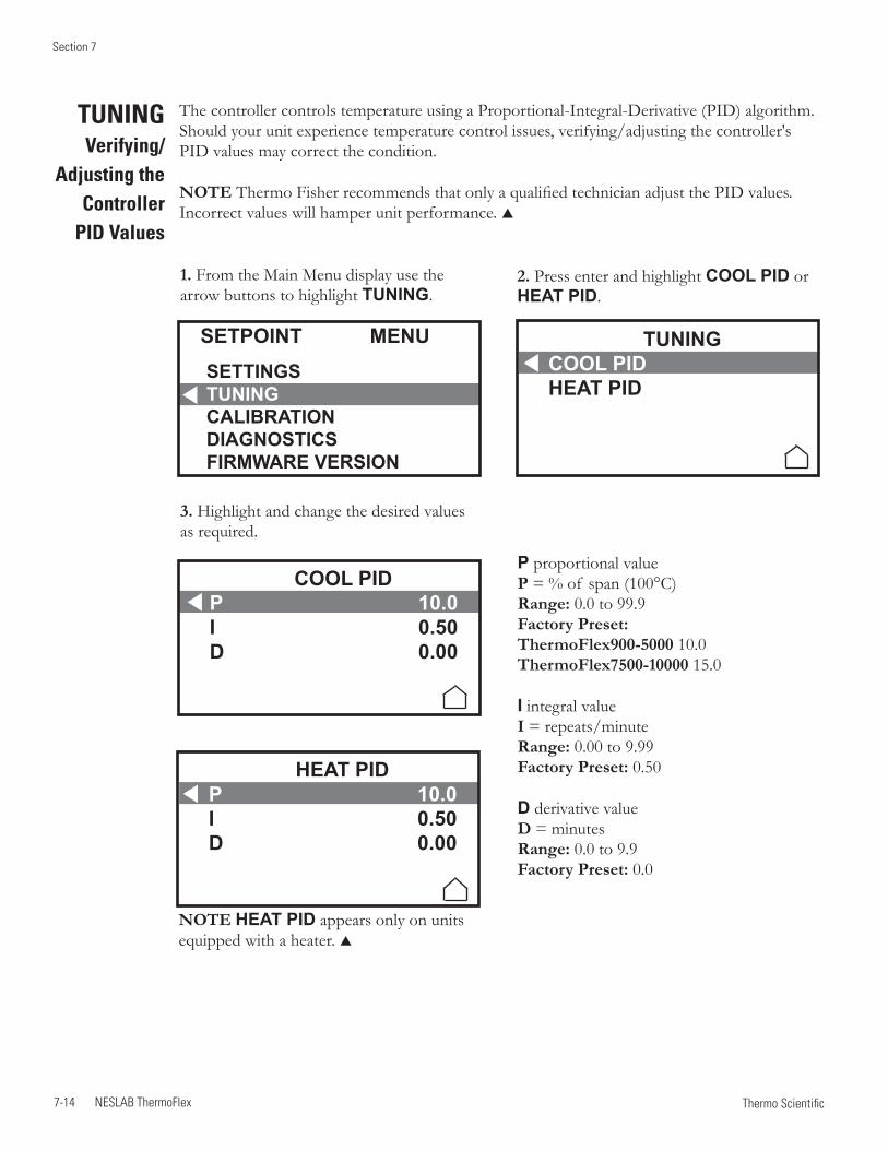
Section 7
7-14 NESLAB ThermoFlex Thermo Scientific
1. From the Main Menu display use the arrow buttons to highlight TUNING.
2. Press enter and highlight COOL PID or HEAT PID.
3. Highlight and change the desired values as required.
TUNING Verifying/
Adjusting the Controller
PID Values
The controller controls temperature using a Proportional-Integral-Derivative (PID) algorithm. Should your unit experience temperature control issues, verifying/adjusting the controller's PID values may correct the condition.
NOTE Thermo Fisher recommends that only a qualified technician adjust the PID values. Incorrect values will hamper unit performance.
P proportional value P = % of span (100°C) Range: 0.0 to 99.9 Factory Preset: ThermoFlex900-5000 10.0 ThermoFlex7500-10000 15.0
I integral value I = repeats/minute Range: 0.00 to 9.99 Factory Preset: 0.50
D derivative value D = minutes Range: 0.0 to 9.9 Factory Preset: 0.0
SETPOINT MENUSETTINGSTUNINGCALIBRATIONDIAGNOSTICS FIRMWARE VERSION
TUNINGCOOL PIDHEAT PID
COOL PIDP 10.0I 0.50D 0.00
HEAT PIDP 10.0I 0.50D 0.00
NOTE HEAT PID appears only on units equipped with a heater.
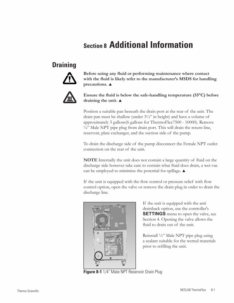
NESLAB ThermoFlex 8-1 Thermo Scientific
Draining
Section 8 Additional Information
Before using any fluid or performing maintenance where contact with the fluid is likely refer to the manufacturer’s MSDS for handling precautions.
Ensure the fluid is below the safe-handling temperature (55°C) before draining the unit.
Position a suitable pan beneath the drain port at the rear of the unit. The drain pan must be shallow (under 3½” in height) and have a volume of approximately 3 gallons(6 gallons for ThermoFlex7500 - 10000). Remove ¼” Male NPT pipe plug from drain port. This will drain the return line, reservoir, plate exchanger, and the suction side of the pump.
To drain the discharge side of the pump disconnect the Female NPT outlet connection on the rear of the unit.
NOTE Internally the unit does not contain a large quantity of fluid on the discharge side however take care to contain what fluid does drain, a wet-vac can be employed to minimize the potential for spillage.
If the unit is equipped with the flow control or pressure relief with flow control option, open the valve or remove the drain plug in order to drain the discharge line.
If the unit is equipped with the anti drainback option, use the controller's SETTINGS menu to open the valve, see Section 4. Opening the valve allows the fluid to drain out of the unit.
Reinstall ¼” Male NPT pipe plug using a sealant suitable for the wetted materials prior to refilling the unit.
Figure 8-1 1/4" Male NPT Reservoir Drain Plug
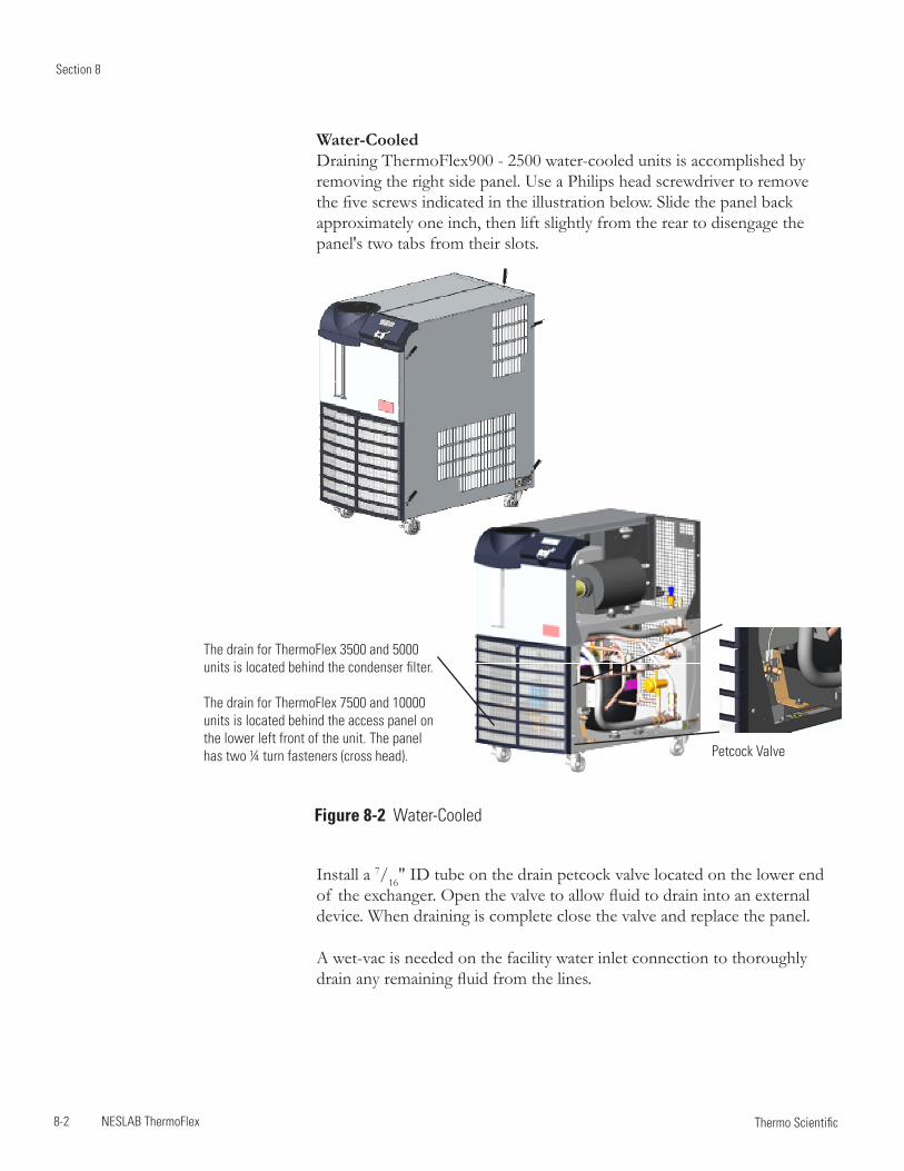
Section 8
8-2 NESLAB ThermoFlex Thermo Scientific
Water-Cooled Draining ThermoFlex900 - 2500 water-cooled units is accomplished by removing the right side panel. Use a Philips head screwdriver to remove the five screws indicated in the illustration below. Slide the panel back approximately one inch, then lift slightly from the rear to disengage the panel's two tabs from their slots.
Petcock Valve
The drain for ThermoFlex 3500 and 5000 units is located behind the condenser filter.
The drain for ThermoFlex 7500 and 10000 units is located behind the access panel on the lower left front of the unit. The panel has two ¼ turn fasteners (cross head).
Figure 8-2 Water-Cooled
Install a 7/16" ID tube on the drain petcock valve located on the lower end of the exchanger. Open the valve to allow fluid to drain into an external device. When draining is complete close the valve and replace the panel.
A wet-vac is needed on the facility water inlet connection to thoroughly drain any remaining fluid from the lines.
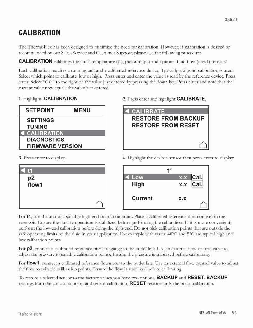
Section 8
NESLAB ThermoFlex 8-3 Thermo Scientific
CALIBRATION
The ThermoFlex has been designed to minimize the need for calibration. However, if calibration is desired or recommended by our Sales, Service and Customer Support, please use the following procedure.
CALIBRATION calibrates the unit's temperature (t1), pressure (p2) and optional fluid flow (flow1) sensors.
Each calibration requires a running unit and a calibrated reference device. Typically, a 2 point calibration is used. Select which point to calibrate, low or high. Press enter and enter the value as read by the reference device. Press enter. Select “Cal.” to the right of the value just entered by pressing the down key. Press enter and note that the current value now equals the value just entered.
1. Highlight CALIBRATION.
3. Press enter to display:
2. Press enter and highlight CALIBRATE.
4. Highlight the desired sensor then press enter to display:
For t1, run the unit to a suitable high-end calibration point. Place a calibrated reference thermometer in the reservoir. Ensure the fluid temperature is stabilized before performing the calibration. If it is more convenient, perform the low-end calibration before doing the high-end. Do not pick calibration points that are outside the safe operating limits of the fluid in your application. For example with water, 40°C and 5°C are typical high and low calibration points.
For p2, connect a calibrated reference pressure gauge to the outlet line. Use an external flow control valve to adjust the pressure to suitable calibration points. Ensure the pressure is stabilized before calibrating.
For flow1, connect a calibrated reference flowmeter to the outlet line. Use an external flow control valve to adjust the flow to suitable calibration points. Ensure the flow is stabilized before calibrating.
To restore a selected sensor to the factory values you have two options, BACkup and REsET. BACkup restores both the controller board and sensor calibration, REsET restores only the board calibration.
sETpOINT MENusETTINGsTuNINGCALIBRATIONDIAGNOsTICsFIRMWARE VERsION
CALIBRATEREsTORE FROM BACkupREsTORE FROM REsET
t1p2flow1
t1Low x.x Cal. High x.x Cal.
Current x.x
Section 8
8-4 NESLAB ThermoFlex Thermo Scientific
Wetted Materials P 1 and P 2 Pumps300 Series Stainless SteelBronzeCarbon GraphiteCeramicFluorocarbon (Viton®)Polysulfone
T 1 PumpsStainless Steel AISI 304Bronze ASTM B62 Bronze ASTM B16Buna NBuna/CeramicBuna/Carbon
TankPolyethylene (standard temp)Polyvinyldiene Diflouride (high temp)BrassEPDM Pyrex®
P 3, P 4 and P 5 Pumps316 Series Stainless SteelCarbonSilicon CarbideFluorocarbon (Viton®)
Plumbing300 Series Stainless SteelBronzeFluorocarbon (Viton®)NickelPolypropyleneEPDMBrassCopperTeflon®
PPS (flow transducer)Nitrile (Buna-n®)
Filter bagPolypropyleneMono-filament nylon
FunnelAcetal Copolymer
Shipment/StorageTransporting and/or storing the unit in near or below freezing temperatures requires draining, see Draining in this Section. Store the unit in the temperature range of -25°C to 60°C (with packaging), and <80% relative humidity.
Do not store the unit for more than 90 days.
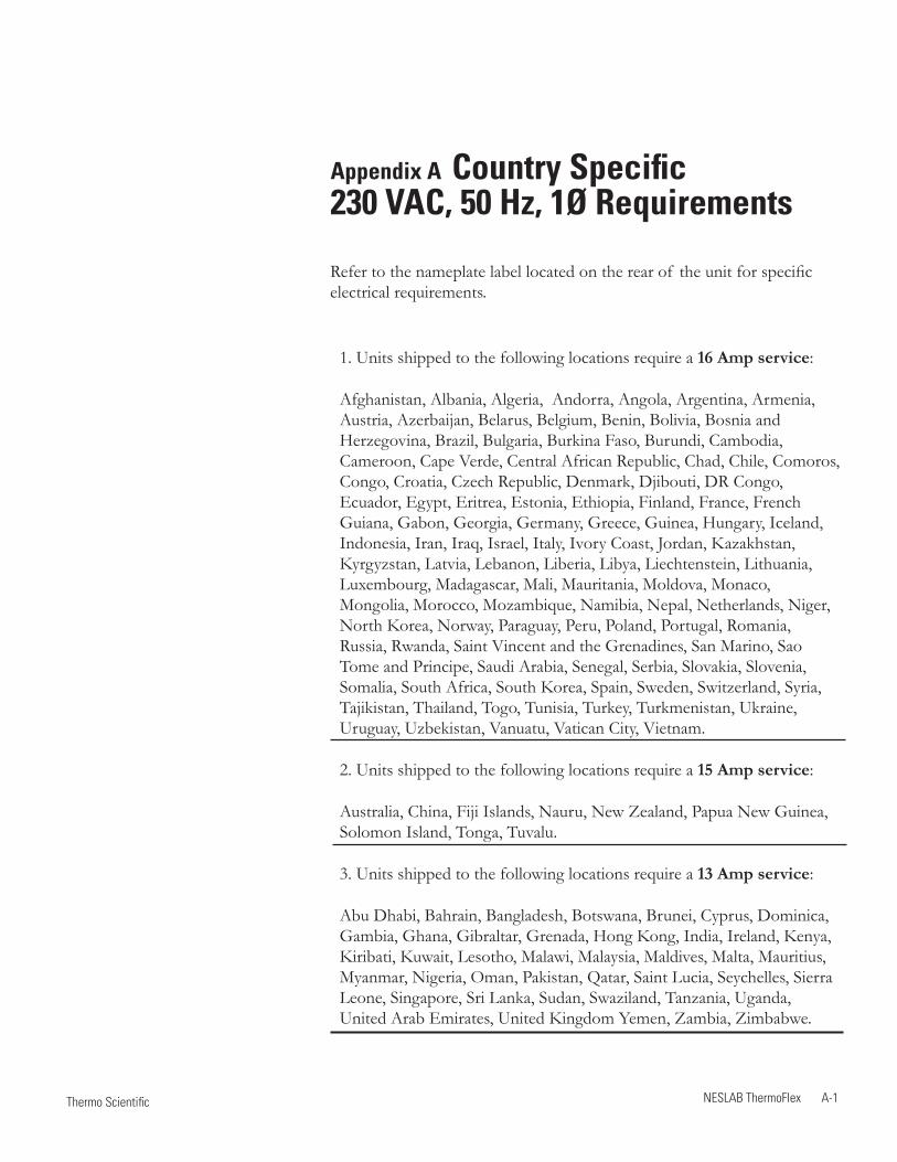
Appendix A Country Specific 230 VAC, 50 Hz, 1Ø Requirements
Refer to the nameplate label located on the rear of the unit for specific electrical requirements.
1. Units shipped to the following locations require a 16 Amp service:
Afghanistan, Albania, Algeria, Andorra, Angola, Argentina, Armenia, Austria, Azerbaijan, Belarus, Belgium, Benin, Bolivia, Bosnia and Herzegovina, Brazil, Bulgaria, Burkina Faso, Burundi, Cambodia, Cameroon, Cape Verde, Central African Republic, Chad, Chile, Comoros, Congo, Croatia, Czech Republic, Denmark, Djibouti, DR Congo, Ecuador, Egypt, Eritrea, Estonia, Ethiopia, Finland, France, French Guiana, Gabon, Georgia, Germany, Greece, Guinea, Hungary, Iceland, Indonesia, Iran, Iraq, Israel, Italy, Ivory Coast, Jordan, Kazakhstan, Kyrgyzstan, Latvia, Lebanon, Liberia, Libya, Liechtenstein, Lithuania, Luxembourg, Madagascar, Mali, Mauritania, Moldova, Monaco, Mongolia, Morocco, Mozambique, Namibia, Nepal, Netherlands, Niger, North Korea, Norway, Paraguay, Peru, Poland, Portugal, Romania, Russia, Rwanda, Saint Vincent and the Grenadines, San Marino, Sao Tome and Principe, Saudi Arabia, Senegal, Serbia, Slovakia, Slovenia, Somalia, South Africa, South Korea, Spain, Sweden, Switzerland, Syria, Tajikistan, Thailand, Togo, Tunisia, Turkey, Turkmenistan, Ukraine, Uruguay, Uzbekistan, Vanuatu, Vatican City, Vietnam.
2. Units shipped to the following locations require a 15 Amp service:
Australia, China, Fiji Islands, Nauru, New Zealand, Papua New Guinea, Solomon Island, Tonga, Tuvalu.
3. Units shipped to the following locations require a 13 Amp service:
Abu Dhabi, Bahrain, Bangladesh, Botswana, Brunei, Cyprus, Dominica, Gambia, Ghana, Gibraltar, Grenada, Hong Kong, India, Ireland, Kenya, Kiribati, Kuwait, Lesotho, Malawi, Malaysia, Maldives, Malta, Mauritius, Myanmar, Nigeria, Oman, Pakistan, Qatar, Saint Lucia, Seychelles, Sierra Leone, Singapore, Sri Lanka, Sudan, Swaziland, Tanzania, Uganda, United Arab Emirates, United Kingdom Yemen, Zambia, Zimbabwe.
NESLAB ThermoFlex A-1 Thermo Scientific
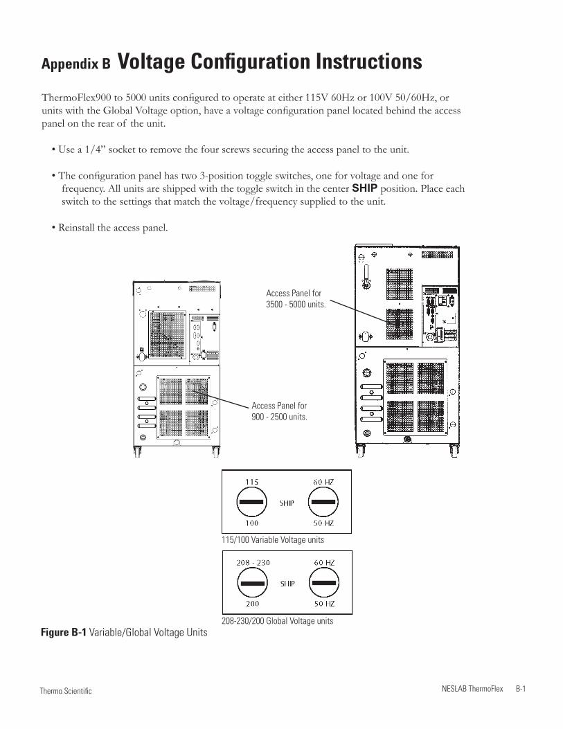
Appendix B Voltage Configuration InstructionsThermoFlex900 to 5000 units configured to operate at either 115V 60Hz or 100V 50/60Hz, or units with the Global Voltage option, have a voltage configuration panel located behind the access panel on the rear of the unit.
• Use a 1/4” socket to remove the four screws securing the access panel to the unit.
• The configuration panel has two 3-position toggle switches, one for voltage and one for frequency. All units are shipped with the toggle switch in the center SHIP position. Place each switch to the settings that match the voltage/frequency supplied to the unit.
• Reinstall the access panel.
Access Panel for 900 - 2500 units.
Access Panel for 3500 - 5000 units.
Figure B-1 Variable/Global Voltage Units
NESLAB ThermoFlex B-1 Thermo Scientific
115/100 Variable Voltage units
208-230/200 Global Voltage units
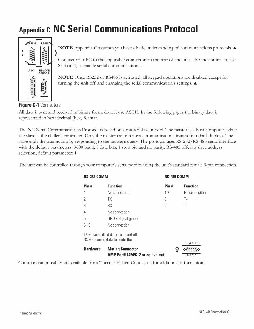
NESLAB ThermoFlex C-1 Thermo Scientific
Appendix C NC Serial Communications Protocol
NOTE Appendix C assumes you have a basic understanding of communications protocols.
Connect your PC to the applicable connector on the rear of the unit. Use the controller, see Section 4, to enable serial communications.
NOTE Once RS232 or RS485 is activated, all keypad operations are disabled except for turning the unit off and changing the serial communication's settings.
Figure C-1 Connectors
RS-232 COMM RS-485 COMM
Pin # Function Pin # Function
1 No connection 1-7 No connection
2 TX 8 T+
3 RX 9 T-
4 No connection
5 GND = Signal ground
6 - 9 No connection
TX = Transmitted data from controller RX = Received data to controller.
Hardware Mating Connector AMP Part# 745492-2 or equivalent
All data is sent and received in binary form, do not use ASCII. In the following pages the binary data is represented in hexadecimal (hex) format.
The NC Serial Communications Protocol is based on a master-slave model. The master is a host computer, while the slave is the chiller's controller. Only the master can initiate a communications transaction (half-duplex). The slave ends the transaction by responding to the master’s query. The protocol uses RS-232/RS-485 serial interface with the default parameters: 9600 baud, 8 data bits, 1 stop bit, and no parity. RS-485 offers a slave address selection, default parameter: 1.
The unit can be controlled through your computer’s serial port by using the unit's standard female 9-pin connection.
Communication cables are available from Thermo Fisher. Contact us for additional information.
5 4 3 2 1
9 8 7 6
1 2 3 4 5
6 7 8 91 2 3 4 5
6 7 8 9
1 2 3 4 5
6 7 8 98 7 6 5 4 3 2 1
15 14 13 12 11 10 9
RS232 RS485
A I/O REMOTE SENSOR
Thermo ScientificC-2 NESLAB ThermoFlex
Appendix C
Thermo Scientific Thermo Scientific
OxCA/OxCC
All commands must be entered in the exact format shown in the tables on the following pages. The tables show all commands available, their format and responses. Controller responses are either the requested data or an error message. The controller response must be received before the host sends the next command.
The host sends a command embedded in a single communications packet, then waits for the controller’s response. If the command is not understood or the checksums do not agree, the controller responds with an error command. Otherwise, the controller responds with the requested data. If the controller fails to respond within 1 second, the host should resend the command.
NOTE All byte values are shown in hex, hex represents the binary values that must be sent to the chiller. Do not use ASCII.
The framing of the communications packet in both directions is:
Checksum region
Lead char Addr-MSB Addr-LSB Command n d-bytes d-byte 1 ... d-byte n Checksum
Lead char 0xCA (RS-232) 0xCC (RS-485) Device address is 1 (RS-232)Addr-msb Mostsignificantbyteof slaveaddress(RS-232:0)Addr-lsb Leastsignificantbyteof slaveaddress(RS-232:1)Command Command byte (see Table of Commands)n d-bytes Number of data bytes to follow d-byte 1 1stdatabyte(thequalifierbyteisconsideredadatabyte)... ...d-byte n nth data byte.Checksum Bitwise inversion of the 1 byte sum of bytes beginning with the mostsignificantaddressbyteandendingwiththebytepreceding the checksum. (To perform a bitwise inversion, "exclusive OR" the one byte sum with FF hex.)
When a command has no value associated with it (e.g. REQ ACK), “n d-bytes” will be set to 0. Values such as temperatureandflowaresentaseither2or4bytesignedintegers,dependingonhowtheyarestoredinthecontroller RAM.
Whenthecontrollersendsavalue,aqualifierbyteissentfirst,followedbya2or4byteinteger(theleastsignificantbyteissentlast).Thequalifierindicatestheprecisionandunitsof thevalue.Thehostdoesnotsendthequalifierbyte;itmustsendthevalueusingthecorrectprecision,unitsandnumberof bytes.Thehostfirstinquiresaboutavalueitwantstochange,thenusesthenumberof databytesandthequalifierbyteitreceivestogenerate the proper integer to send.
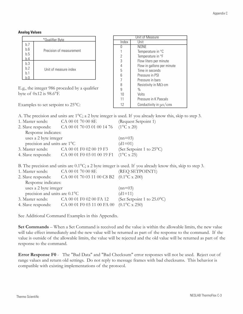
Thermo Scientific
Appendix C
NESLAB ThermoFlex C-3 Thermo Scientific
Analog Values
*Qualifier Byteb.7 b.6 b.5 b.4 b.3 b.2 b.1 b.0
E.g.,theinteger986procededbyaqualifier byte of 0x12 is 98.6°F.
Examples to set setpoint to 25°C:
A.Theprecisionandunitsare1°C;a2byteintegerisused.If youalreadyknowthis,skiptostep3.1. Master sends: CA 00 01 70 00 8E (Request Setpoint 1)2. Slave responds: CA 00 01 70 03 01 00 14 76 (1°C x 20) Response indicates: uses a 2 byte integer (nn=03) precision and units are 1°C (d1=01)3. Master sends: CA 00 01 F0 02 00 19 F3 (Set Setpoint 1 to 25°C)4. Slave responds: CA 00 01 F0 03 01 00 19 F1 (1°C x 25)
B.Theprecisionandunitsare0.1°C;a2byteintegerisused.If youalreadyknowthis,skiptostep3.1. Master sends: CA 00 01 70 00 8E (REQ SETPOINT1)2. Slave responds: CA 00 01 70 03 11 00 C8 B2 (0.1°C x 200) Response indicates: uses a 2 byte integer (nn=03) precision and units are 0.1°C (d1=11)3. Master sends: CA 00 01 F0 02 00 FA 12 (Set Setpoint 1 to 25.0°C)4. Slave responds: CA 00 01 F0 03 11 00 FA 00 (0.1°C x 250)
See Additional Command Examples in this Appendix.
Set Commands – When a Set Command is received and the value is within the allowable limits, the new value will take effect immediately and the new value will be returned as part of the response to the command. If the value is outside of the allowable limits, the value will be rejected and the old value will be returned as part of the response to the command.
Error Response F0 - The "Bad Data" and "Bad Checksum" error responses will not be used. Reject out of range values and return old settings. Do not reply to message frames with bad checksums. This behavior is compatible with existing implementations of the protocol.
Unit of MeasureIndex Unit0 NONE1 Temperature in °C2 Temperature in °F3 Flow liters per minute4 Flow in gallons per minute5 Time in seconds6 Pressure in PSI7 Pressure in bars8 Resistivity in MΩ-cm 9 % 10 Volts 11 Pressure in K Pascals 12 Conductivity in μs/cm
Precision of measurement
Unit of measure index
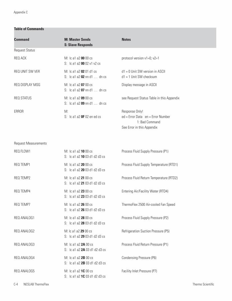
Thermo ScientificC-4 NESLAB ThermoFlex
Appendix C
Thermo Scientific Thermo Scientific
Table of Commands
Command M: Master Sends Notes S: Slave RespondsRequest Status
REQ ACK M: lc a1 a2 00 00 cs protocol version v1=0; v2=1 S: lc a1 a2 00 02 v1 v2 cs
REQ UNIT SW VER M: lc a1 a2 02 01 d1 cs d1 = 0 Unit SW version in ASCII S: lc a1 a2 02 nn d1 … dn cs d1 = 1 Unit SW checksum
REQ DISPLAY MSG M: lc a1 a2 07 00 cs Display message in ASCII S: lc a1 a2 07 nn d1 … dn cs
REQ STATUS M: lc a1 a2 09 00 cs see Request Status Table in this Appendix S: lc a1 a2 09 nn d1 … dn cs
ERROR M: Response Only! S: lc a1 a2 0F 02 en ed cs ed = Error Data en = Error Number 1: Bad Command See Error in this Appendix
Request Measurements
REQ FLOW1 M: lc a1 a2 10 00 cs Process Fluid Supply Pressure (P1) S: lc a1 a2 10 03 d1 d2 d3 cs
REQ TEMP1 M: lc a1 a2 20 00 cs Process Fluid Supply Temperature (RTD1) S: lc a1 a2 20 03 d1 d2 d3 cs
REQ TEMP2 M: lc a1 a2 21 00 cs Process Fluid Return Temperature (RTD2) S: lc a1 a2 21 03 d1 d2 d3 cs
REQ TEMP4 M: lc a1 a2 23 00 cs Entering Air/Facility Water (RTD4) S: lc a1 a2 23 03 d1 d2 d3 cs
REQ TEMP7 M: lc a1 a2 26 00 cs ThermoFlex 2500 Air-cooled Fan Speed S: lc a1 a2 26 03 d1 d2 d3 cs
REQ ANALOG1 M: lc a1 a2 28 00 cs Process Fluid Supply Pressure (P2) S: lc a1 a2 28 03 d1 d2 d3 cs
REQ ANALOG2 M: lc a1 a2 29 00 cs Refrigeration Suction Pressure (P5) S: lc a1 a2 29 03 d1 d2 d3 cs
REQ ANALOG3 M: lc a1 a2 2A 00 cs Process Fluid Return Pressure (P1) S: lc a1 a2 2A 03 d1 d2 d3 cs
REQ ANALOG4 M: lc a1 a2 2B 00 cs Condensing Pressure (P6) S: lc a1 a2 2B 03 d1 d2 d3 cs
REQ ANALOG5 M: lc a1 a2 1C 00 cs Facility Inlet Pressure (P7) S: lc a1 a2 1C 03 d1 d2 d3 cs
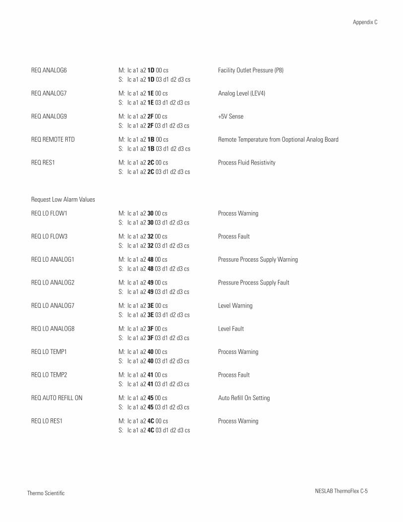
Thermo Scientific
Appendix C
NESLAB ThermoFlex C-5 Thermo Scientific
REQ ANALOG6 M: lc a1 a2 1D 00 cs Facility Outlet Pressure (P8) S: lc a1 a2 1D 03 d1 d2 d3 cs
REQ ANALOG7 M: lc a1 a2 1E 00 cs Analog Level (LEV4) S: lc a1 a2 1E 03 d1 d2 d3 cs
REQ ANALOG9 M: lc a1 a2 2F 00 cs +5V Sense S: lc a1 a2 2F 03 d1 d2 d3 cs
REQ REMOTE RTD M: lc a1 a2 1B 00 cs Remote Temperature from Ooptional Analog Board S: lc a1 a2 1B 03 d1 d2 d3 cs
REQ RES1 M: lc a1 a2 2C 00 cs Process Fluid Resistivity S: lc a1 a2 2C 03 d1 d2 d3 cs
Request Low Alarm Values
REQ LO FLOW1 M: lc a1 a2 30 00 cs Process Warning S: lc a1 a2 30 03 d1 d2 d3 cs
REQ LO FLOW3 M: lc a1 a2 32 00 cs Process Fault S: lc a1 a2 32 03 d1 d2 d3 cs
REQ LO ANALOG1 M: lc a1 a2 48 00 cs Pressure Process Supply Warning S: lc a1 a2 48 03 d1 d2 d3 cs
REQ LO ANALOG2 M: lc a1 a2 49 00 cs Pressure Process Supply Fault S: lc a1 a2 49 03 d1 d2 d3 cs
REQ LO ANALOG7 M: lc a1 a2 3E 00 cs Level Warning S: lc a1 a2 3E 03 d1 d2 d3 cs
REQ LO ANALOG8 M: lc a1 a2 3F 00 cs Level Fault S: lc a1 a2 3F 03 d1 d2 d3 cs
REQ LO TEMP1 M: lc a1 a2 40 00 cs Process Warning S: lc a1 a2 40 03 d1 d2 d3 cs
REQ LO TEMP2 M: lc a1 a2 41 00 cs Process Fault S: lc a1 a2 41 03 d1 d2 d3 cs
REQ AUTO REFILL ON M: lc a1 a2 45 00 cs Auto Refill On Setting S: lc a1 a2 45 03 d1 d2 d3 cs
REQ LO RES1 M: lc a1 a2 4C 00 cs Process Warning S: lc a1 a2 4C 03 d1 d2 d3 cs
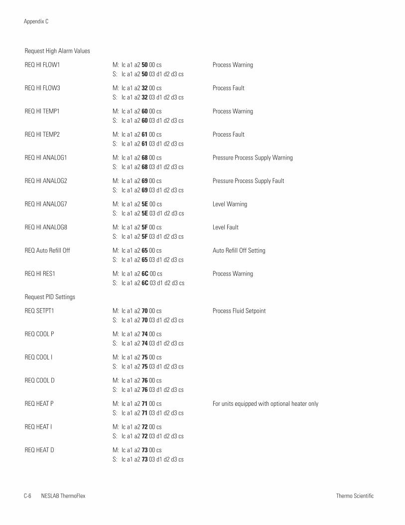
Thermo ScientificC-6 NESLAB ThermoFlex
Appendix C
Thermo Scientific Thermo Scientific
Request High Alarm Values
REQ HI FLOW1 M: lc a1 a2 50 00 cs Process Warning S: lc a1 a2 50 03 d1 d2 d3 cs
REQ HI FLOW3 M: lc a1 a2 32 00 cs Process Fault S: lc a1 a2 32 03 d1 d2 d3 cs
REQ HI TEMP1 M: lc a1 a2 60 00 cs Process Warning S: lc a1 a2 60 03 d1 d2 d3 cs
REQ HI TEMP2 M: lc a1 a2 61 00 cs Process Fault S: lc a1 a2 61 03 d1 d2 d3 cs
REQ HI ANALOG1 M: lc a1 a2 68 00 cs Pressure Process Supply Warning S: lc a1 a2 68 03 d1 d2 d3 cs
REQ HI ANALOG2 M: lc a1 a2 69 00 cs Pressure Process Supply Fault S: lc a1 a2 69 03 d1 d2 d3 cs
REQ HI ANALOG7 M: lc a1 a2 5E 00 cs Level Warning S: lc a1 a2 5E 03 d1 d2 d3 cs
REQ HI ANALOG8 M: lc a1 a2 5F 00 cs Level Fault S: lc a1 a2 5F 03 d1 d2 d3 cs
REQ Auto Refill Off M: lc a1 a2 65 00 cs Auto Refill Off Setting S: lc a1 a2 65 03 d1 d2 d3 cs
REQ HI RES1 M: lc a1 a2 6C 00 cs Process Warning S: lc a1 a2 6C 03 d1 d2 d3 cs
Request PID Settings
REQ SETPT1 M: lc a1 a2 70 00 cs Process Fluid Setpoint S: lc a1 a2 70 03 d1 d2 d3 cs
REQ COOL P M: lc a1 a2 74 00 cs S: lc a1 a2 74 03 d1 d2 d3 cs
REQ COOL I M: lc a1 a2 75 00 cs S: lc a1 a2 75 03 d1 d2 d3 cs
REQ COOL D M: lc a1 a2 76 00 cs S: lc a1 a2 76 03 d1 d2 d3 cs
REQ HEAT P M: lc a1 a2 71 00 cs For units equipped with optional heater only S: lc a1 a2 71 03 d1 d2 d3 cs
REQ HEAT I M: lc a1 a2 72 00 cs S: lc a1 a2 72 03 d1 d2 d3 cs
REQ HEAT D M: lc a1 a2 73 00 cs S: lc a1 a2 73 03 d1 d2 d3 cs
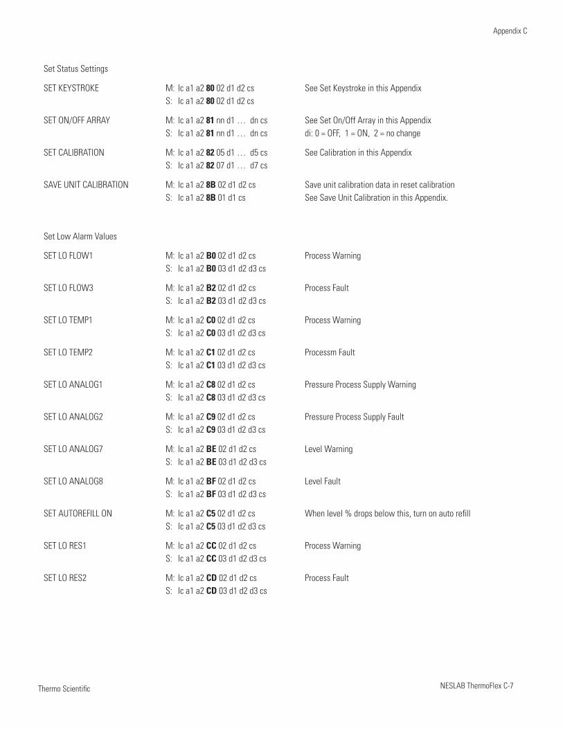
Thermo Scientific
Appendix C
NESLAB ThermoFlex C-7 Thermo Scientific
Set Status Settings
SET KEYSTROKE M: lc a1 a2 80 02 d1 d2 cs See Set Keystroke in this Appendix S: lc a1 a2 80 02 d1 d2 cs
SET ON/OFF ARRAY M: lc a1 a2 81 nn d1 … dn cs See Set On/Off Array in this Appendix S: lc a1 a2 81 nn d1 … dn cs di: 0 = OFF, 1 = ON, 2 = no change
SET CALIBRATION M: lc a1 a2 82 05 d1 … d5 cs See Calibration in this Appendix S: lc a1 a2 82 07 d1 … d7 cs
SAVE UNIT CALIBRATION M: lc a1 a2 8B 02 d1 d2 cs Save unit calibration data in reset calibration S: lc a1 a2 8B 01 d1 cs See Save Unit Calibration in this Appendix.
Set Low Alarm Values
SET LO FLOW1 M: lc a1 a2 B0 02 d1 d2 cs Process Warning S: lc a1 a2 B0 03 d1 d2 d3 cs
SET LO FLOW3 M: lc a1 a2 B2 02 d1 d2 cs Process Fault S: lc a1 a2 B2 03 d1 d2 d3 cs
SET LO TEMP1 M: lc a1 a2 C0 02 d1 d2 cs Process Warning S: lc a1 a2 C0 03 d1 d2 d3 cs
SET LO TEMP2 M: lc a1 a2 C1 02 d1 d2 cs Processm Fault S: lc a1 a2 C1 03 d1 d2 d3 cs
SET LO ANALOG1 M: lc a1 a2 C8 02 d1 d2 cs Pressure Process Supply Warning S: lc a1 a2 C8 03 d1 d2 d3 cs
SET LO ANALOG2 M: lc a1 a2 C9 02 d1 d2 cs Pressure Process Supply Fault S: lc a1 a2 C9 03 d1 d2 d3 cs
SET LO ANALOG7 M: lc a1 a2 BE 02 d1 d2 cs Level Warning S: lc a1 a2 BE 03 d1 d2 d3 cs
SET LO ANALOG8 M: lc a1 a2 BF 02 d1 d2 cs Level Fault S: lc a1 a2 BF 03 d1 d2 d3 cs
SET AUTOREFILL ON M: lc a1 a2 C5 02 d1 d2 cs When level % drops below this, turn on auto refill S: lc a1 a2 C5 03 d1 d2 d3 cs
SET LO RES1 M: lc a1 a2 CC 02 d1 d2 cs Process Warning S: lc a1 a2 CC 03 d1 d2 d3 cs
SET LO RES2 M: lc a1 a2 CD 02 d1 d2 cs Process Fault S: lc a1 a2 CD 03 d1 d2 d3 cs
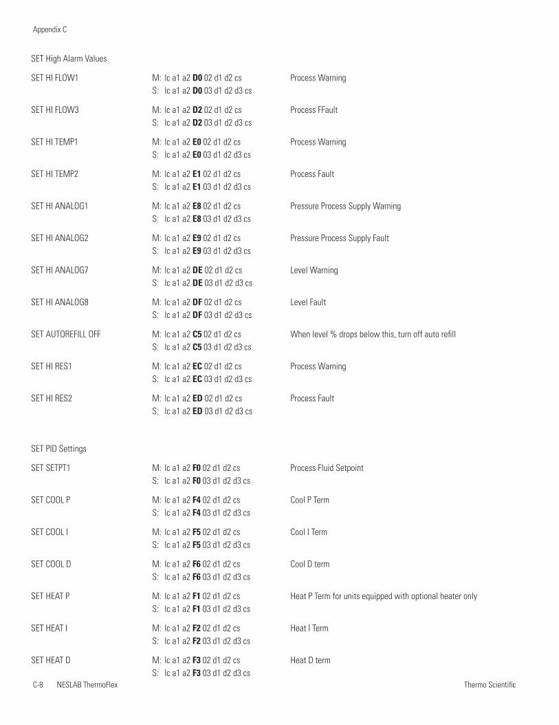
Thermo ScientificC-8 NESLAB ThermoFlex
Appendix C
Thermo Scientific Thermo Scientific
SET High Alarm Values
SET HI FLOW1 M: lc a1 a2 D0 02 d1 d2 cs Process Warning S: lc a1 a2 D0 03 d1 d2 d3 cs
SET HI FLOW3 M: lc a1 a2 D2 02 d1 d2 cs Process FFault S: lc a1 a2 D2 03 d1 d2 d3 cs
SET HI TEMP1 M: lc a1 a2 E0 02 d1 d2 cs Process Warning S: lc a1 a2 E0 03 d1 d2 d3 cs
SET HI TEMP2 M: lc a1 a2 E1 02 d1 d2 cs Process Fault S: lc a1 a2 E1 03 d1 d2 d3 cs
SET HI ANALOG1 M: lc a1 a2 E8 02 d1 d2 cs Pressure Process Supply Warning S: lc a1 a2 E8 03 d1 d2 d3 cs
SET HI ANALOG2 M: lc a1 a2 E9 02 d1 d2 cs Pressure Process Supply Fault S: lc a1 a2 E9 03 d1 d2 d3 cs
SET HI ANALOG7 M: lc a1 a2 DE 02 d1 d2 cs Level Warning S: lc a1 a2 DE 03 d1 d2 d3 cs
SET HI ANALOG8 M: lc a1 a2 DF 02 d1 d2 cs Level Fault S: lc a1 a2 DF 03 d1 d2 d3 cs
SET AUTOREFILL OFF M: lc a1 a2 C5 02 d1 d2 cs When level % drops below this, turn off auto refill S: lc a1 a2 C5 03 d1 d2 d3 cs
SET HI RES1 M: lc a1 a2 EC 02 d1 d2 cs Process Warning S: lc a1 a2 EC 03 d1 d2 d3 cs
SET HI RES2 M: lc a1 a2 ED 02 d1 d2 cs Process Fault S: lc a1 a2 ED 03 d1 d2 d3 cs
SET PID Settings
SET SETPT1 M: lc a1 a2 F0 02 d1 d2 cs Process Fluid Setpoint S: lc a1 a2 F0 03 d1 d2 d3 cs
SET COOL P M: lc a1 a2 F4 02 d1 d2 cs Cool P Term S: lc a1 a2 F4 03 d1 d2 d3 cs
SET COOL I M: lc a1 a2 F5 02 d1 d2 cs Cool I Term S: lc a1 a2 F5 03 d1 d2 d3 cs
SET COOL D M: lc a1 a2 F6 02 d1 d2 cs Cool D term S: lc a1 a2 F6 03 d1 d2 d3 cs
SET HEAT P M: lc a1 a2 F1 02 d1 d2 cs Heat P Term for units equipped with optional heater only S: lc a1 a2 F1 03 d1 d2 d3 cs
SET HEAT I M: lc a1 a2 F2 02 d1 d2 cs Heat I Term S: lc a1 a2 F2 03 d1 d2 d3 cs
SET HEAT D M: lc a1 a2 F3 02 d1 d2 cs Heat D term S: lc a1 a2 F3 03 d1 d2 d3 cs
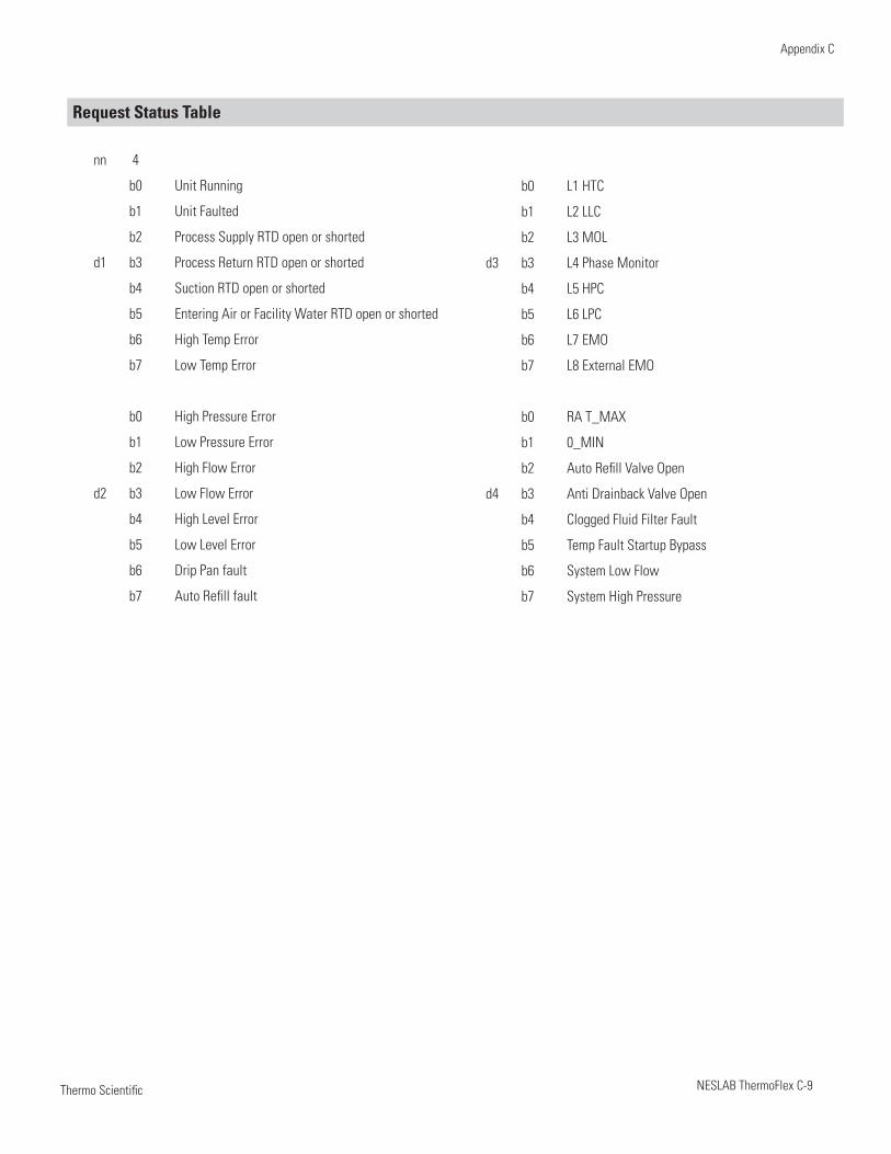
Thermo Scientific
Appendix C
NESLAB ThermoFlex C-9 Thermo Scientific
Request Status Table
nn 4
b0 Unit Running
b1 Unit Faulted
b2 Process Supply RTD open or shorted
d1 b3 Process Return RTD open or shorted
b4 Suction RTD open or shorted
b5 Entering Air or Facility Water RTD open or shorted
b6 High Temp Error
b7 Low Temp Error
b0 High Pressure Error
b1 Low Pressure Error
b2 High Flow Error
d2 b3 Low Flow Error
b4 High Level Error
b5 Low Level Error
b6 Drip Pan fault
b7 Auto Refill fault
b0 L1 HTC
b1 L2 LLC
b2 L3 MOL
d3 b3 L4 Phase Monitor
b4 L5 HPC
b5 L6 LPC
b6 L7 EMO
b7 L8 External EMO
b0 RA T_MAX
b1 0_MIN
b2 Auto Refill Valve Open
d4 b3 Anti Drainback Valve Open
b4 Clogged Fluid Filter Fault
b5 Temp Fault Startup Bypass
b6 System Low Flow
b7 System High Pressure
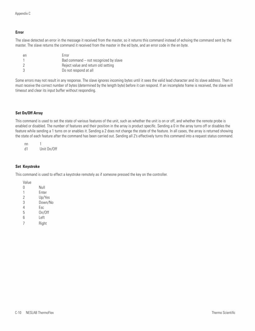
Thermo ScientificC-10 NESLAB ThermoFlex
Appendix C
Thermo Scientific Thermo Scientific
Error The slave detected an error in the message it received from the master, so it returns this command instead of echoing the command sent by the master. The slave returns the command it received from the master in the ed byte, and an error code in the en byte.
en Error1 Bad command – not recognized by slave2 Reject value and return old setting3 Do not respond at all
Some errors may not result in any response. The slave ignores incoming bytes until it sees the valid lead character and its slave address. Then it must receive the correct number of bytes (determined by the length byte) before it can respond. If an incomplete frame is received, the slave will timeout and clear its input buffer without responding.
Set On/Off Array
This command is used to set the state of various features of the unit, such as whether the unit is on or off, and whether the remote probe is enabled or disabled. The number of features and their position in the array is product specific. Sending a 0 in the array turns off or disables the feature while sending a 1 turns on or enables it. Sending a 2 does not change the state of the feature. In all cases, the array is returned showing the state of each feature after the command has been carried out. Sending all 2’s effectively turns this command into a request status command.
nn 1d1 Unit On/Off
Set Keystroke
This command is used to effect a keystroke remotely as if someone pressed the key on the controller.
Value 0 Null1 Enter2 Up/Yes3 Down/No4 Esc5 On/Off6 Left 7 Right
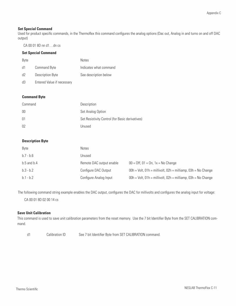
Thermo Scientific
Appendix C
NESLAB ThermoFlex C-11 Thermo Scientific
Set Special CommandUsed for product specific commands, in the Thermoflex this command configures the analog options (Dac out, Analog in and turns on and off DAC output)
CA 00 01 8D nn d1…dn cs
Set Special Command
Byte Notes
d1 Command Byte Indicates what command
d2 Description Byte See description below
d3 Entered Value if necessary
Command Byte
Command Description
00 Set Analog Option
01 Set Resistivity Control (for Basic derivatives)
02 Unused
Description Byte
Byte Notes
b.7 - b.6 Unused
b.5 and b.4 Remote DAC output enable 00 = Off, 01 = On, 1x = No Change
b.3 - b.2 Configure DAC Output 00h = Volt, 01h = millivolt, 02h = milliamp, 03h = No Change
b.1 - b.2 Configure Analog Input 00h = Volt, 01h = millivolt, 02h = milliamp, 03h = No Change
The following command string example enables the DAC output, configures the DAC for millivolts and configures the analog input for voltage:
CA 00 01 8D 02 00 14 cs
Save Unit Calibration This command is used to save unit calibration parameters from the reset memory. Use the 7 bit Identifier Byte from the SET CALIBRATION com-mand.
d1 Calibration ID See 7 bit Identifier Byte from SET CALIBRATION command.
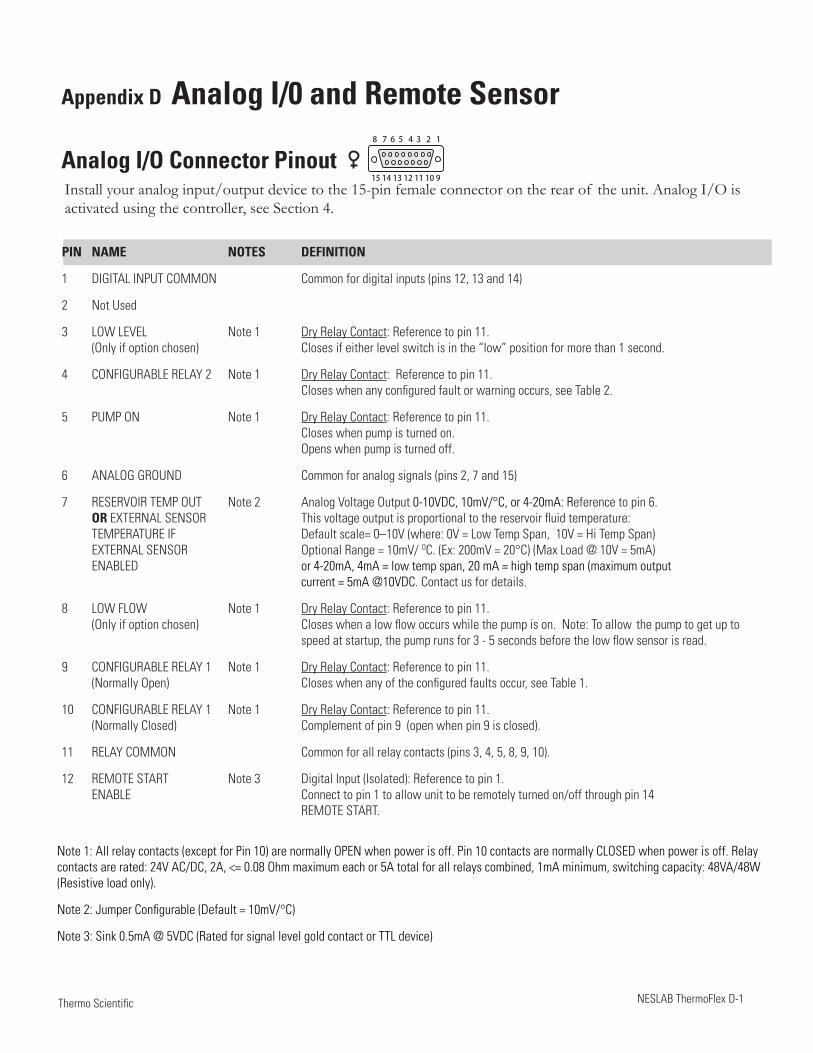
NESLAB ThermoFlex D-1 Thermo Scientific
Appendix D Analog I/0 and Remote Sensor
Analog I/O Connector PinoutInstall your analog input/output device to the 15-pin female connector on the rear of the unit. Analog I/O is activated using the controller, see Section 4.
PIN NAME NOTES DEFINITION
1 DIGITAL INPUT COMMON Common for digital inputs (pins 12, 13 and 14)
2 Not Used
3 LOW LEVEL Note 1 Dry Relay Contact: Reference to pin 11. (Only if option chosen) Closes if either level switch is in the “low” position for more than 1 second.
4 CONFIGURABLE RELAY 2 Note 1 Dry Relay Contact: Reference to pin 11. Closes when any configured fault or warning occurs, see Table 2.
5 PUMP ON Note 1 Dry Relay Contact: Reference to pin 11. Closes when pump is turned on. Opens when pump is turned off.
6 ANALOG GROUND Common for analog signals (pins 2, 7 and 15)
7 RESERVOIR TEMP OUT Note 2 Analog Voltage Output 0-10VDC, 10mV/°C, or 4-20mA: Reference to pin 6. OR EXTERNAL SENSOR This voltage output is proportional to the reservoir fluid temperature: TEMPERATURE IF Default scale= 0–10V (where: 0V = Low Temp Span, 10V = Hi Temp Span) EXTERNAL SENSOR Optional Range = 10mV/ OC. (Ex: 200mV = 20°C) (Max Load @ 10V = 5mA) ENABLED or 4-20mA, 4mA = low temp span, 20 mA = high temp span (maximum output current = 5mA @10VDC. Contact us for details.
8 LOW FLOW Note 1 Dry Relay Contact: Reference to pin 11. (Only if option chosen) Closes when a low flow occurs while the pump is on. Note: To allow the pump to get up to speed at startup, the pump runs for 3 - 5 seconds before the low flow sensor is read.
9 CONFIGURABLE RELAY 1 Note 1 Dry Relay Contact: Reference to pin 11. (Normally Open) Closes when any of the configured faults occur, see Table 1.
10 CONFIGURABLE RELAY 1 Note 1 Dry Relay Contact: Reference to pin 11. (Normally Closed) Complement of pin 9 (open when pin 9 is closed).
11 RELAY COMMON Common for all relay contacts (pins 3, 4, 5, 8, 9, 10).
12 REMOTE START Note 3 Digital Input (Isolated): Reference to pin 1. ENABLE Connect to pin 1 to allow unit to be remotely turned on/off through pin 14 REMOTE START.
Note 1: All relay contacts (except for Pin 10) are normally OPEN when power is off. Pin 10 contacts are normally CLOSED when power is off. Relay contacts are rated: 24V AC/DC, 2A, <= 0.08 Ohm maximum each or 5A total for all relays combined, 1mA minimum, switching capacity: 48VA/48W (Resistive load only).
Note 2: Jumper Configurable (Default = 10mV/°C)
Note 3: Sink 0.5mA @ 5VDC (Rated for signal level gold contact or TTL device)
8 7 6 5 4 3 2 1
15 14 13 12 11 10 9
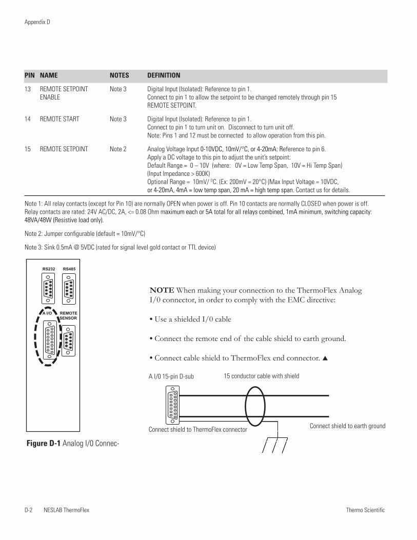
Thermo ScientificD-2 NESLAB ThermoFlex
Appendix D
Thermo Scientific Thermo Scientific
PIN NAME NOTES DEFINITION
13 REMOTE SETPOINT Note 3 Digital Input (Isolated): Reference to pin 1. ENABLE Connect to pin 1 to allow the setpoint to be changed remotely through pin 15 REMOTE SETPOINT.
14 REMOTE START Note 3 Digital Input (Isolated): Reference to pin 1. Connect to pin 1 to turn unit on. Disconnect to turn unit off. Note: Pins 1 and 12 must be connected to allow operation from this pin.
15 REMOTE SETPOINT Note 2 Analog Voltage Input 0-10VDC, 10mV/°C, or 4-20mA: Reference to pin 6. Apply a DC voltage to this pin to adjust the unit’s setpoint: Default Range = 0 – 10V (where: 0V = Low Temp Span, 10V = Hi Temp Span) (Input Impedance > 600K) Optional Range = 10mV/ OC. (Ex: 200mV = 20°C) (Max Input Voltage = 10VDC, or 4-20mA, 4mA = low temp span, 20 mA = high temp span. Contact us for details.
Note 1: All relay contacts (except for Pin 10) are normally OPEN when power is off. Pin 10 contacts are normally CLOSED when power is off. Relay contacts are rated: 24V AC/DC, 2A, <= 0.08 Ohm maximum each or 5A total for all relays combined, 1mA minimum, switching capacity: 48VA/48W (Resistive load only).
Note 2: Jumper configurable (default = 10mV/°C)
Note 3: Sink 0.5mA @ 5VDC (rated for signal level gold contact or TTL device)
Figure D-1 Analog I/0 Connec-
NOTE When making your connection to the ThermoFlex Analog I/0 connector, in order to comply with the EMC directive:
• Use a shielded I/0 cable
• Connect the remote end of the cable shield to earth ground.
• Connect cable shield to ThermoFlex end connector.
A I/0 15-pin D-sub 15 conductor cable with shield
Connect shield to earth groundConnect shield to ThermoFlex connector
1 2 3 4 5
6 7 8 91 2 3 4 5
6 7 8 9
1 2 3 4 5
6 7 8 98 7 6 5 4 3 2 1
15 14 13 12 11 10 9
RS232 RS485
A I/O REMOTE SENSOR
8 7 6 5 4 3 2 1
15 14 13 12 11 10 9
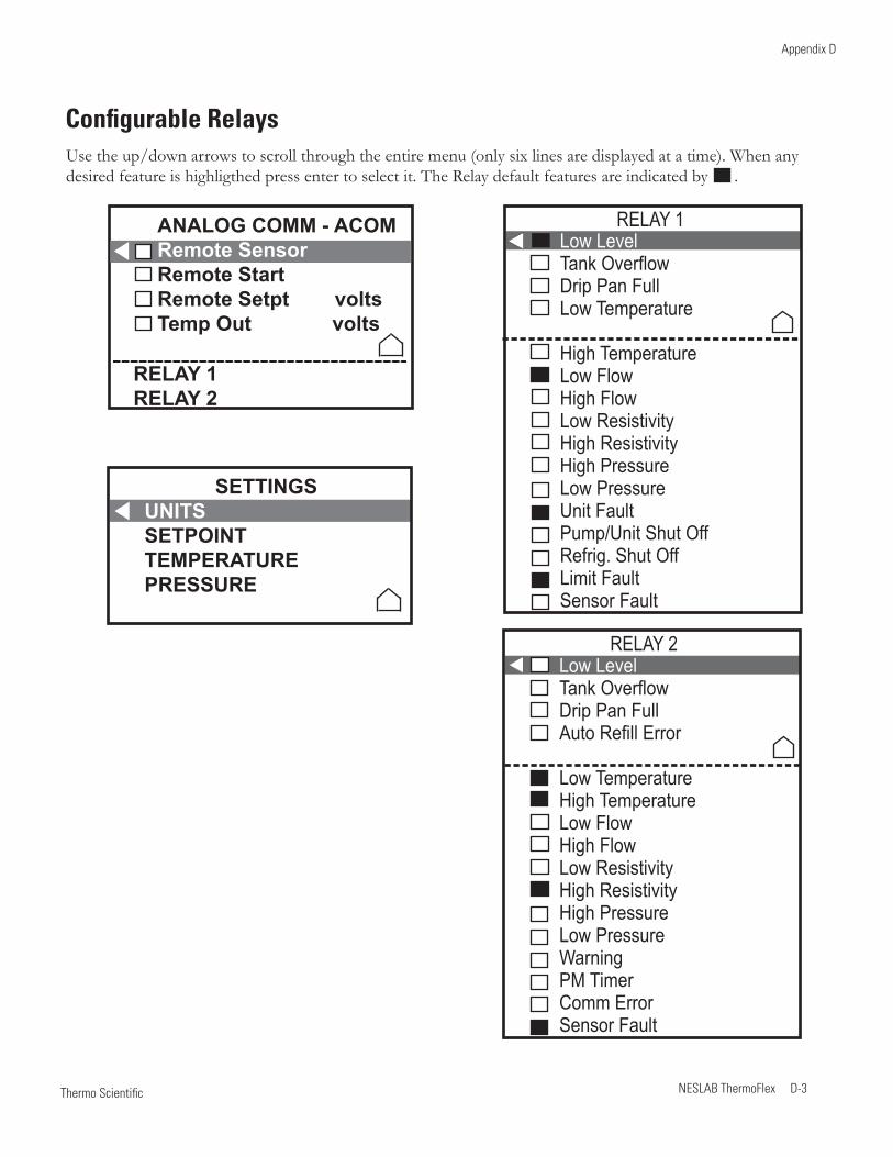
Thermo Scientific
Appendix D
NESLAB ThermoFlex D-3 Thermo Scientific
Configurable RelaysUse the up/down arrows to scroll through the entire menu (only six lines are displayed at a time). When any desired feature is highligthed press enter to select it. The Relay default features are indicated by .
ANALOG COMM - ACOMRemote SensorRemote Start Remote Setpt voltsTemp Out volts
RELAY 1RELAY 2
SETTINGSUNITSSETPOINTTEMPERATUREPRESSURE
Low LevelTank OverflowDrip Pan FullAuto Refill Error
Low TemperatureHigh TemperatureLow FlowHigh FlowLow ResistivityHigh ResistivityHigh PressureLow PressureWarningPM TimerComm ErrorSensor Fault
RELAY 2
Low LevelTank OverflowDrip Pan FullLow Temperature
High TemperatureLow FlowHigh FlowLow ResistivityHigh ResistivityHigh PressureLow PressureUnit FaultPump/Unit Shut OffRefrig. Shut OffLimit FaultSensor Fault
RELAY 1
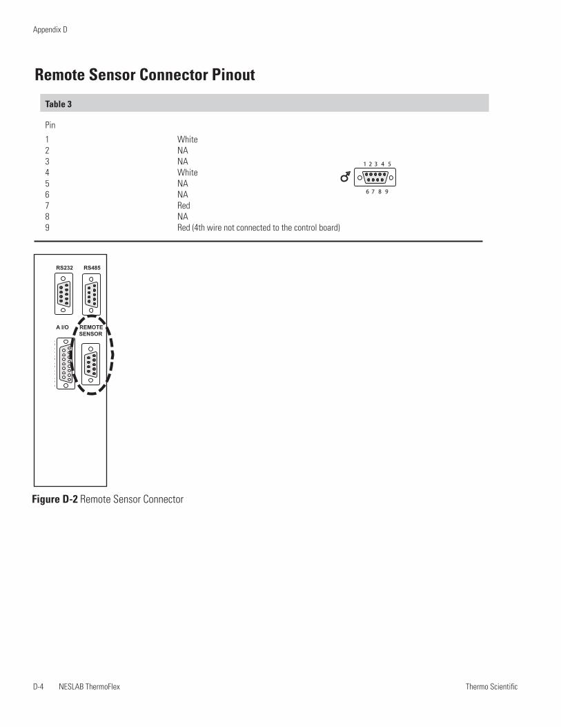
Thermo ScientificD-4 NESLAB ThermoFlex
Appendix D
Thermo Scientific
Table 3
Pin
1 White 2 NA 3 NA 4 White 5 NA 6 NA 7 Red 8 NA 9 Red (4th wire not connected to the control board)
Remote Sensor Connector Pinout
1 2 3 4 5
6 7 8 9
Figure D-2 Remote Sensor Connector
1 2 3 4 5
6 7 8 91 2 3 4 5
6 7 8 9
1 2 3 4 5
6 7 8 98 7 6 5 4 3 2 1
15 14 13 12 11 10 9
RS232 RS485
A I/O REMOTE SENSOR
WARRANTY
Thermo Fisher Scientific warrants for 24 months from date of shipment the Thermo Scientific NESLAB ThermoFlex unit according to the following terms.
Any part of the unit manufactured or supplied by Thermo Fisher Scientific and found in the reasonable judgment of Thermo Fisher to be defective in material or workmanship will be repaired at an authorized Thermo Fisher Repair Depot without charge for parts or labor. The unit, including any defective part must be returned to an authorized Thermo Fisher Repair Depot within the warranty period. The expense of returning the unit to the authorized Thermo Fisher Repair Depot for warranty service will be paid for by the buyer. Our responsibility in respect to warranty claims is limited to performing the required repairs or replacements, and no claim of breach of warranty shall be cause for cancellation or recision of the contract of sales of any unit. With respect to units that qualify for field service repairs, Thermo Fisher Scientific’s responsibility is limited to the component parts necessary for the repair and the labor that is required on site to perform the repair. Any travel labor or mileage charges are the financial responsibility of the buyer.
The buyer shall be responsible for any evaluation or warranty service call (including labor charges) if no defects are found with the Thermo Scientific product.
This warranty does not cover any unit that has been subject to misuse, neglect, or accident. This warranty does not apply to any damage to the unit that is the result of improper installation or maintenance, or to any unit that has been operated or maintained in any way contrary to the operating or maintenance instructions specified in this Instruction and Operation Manual. This warranty does not cover any unit that has been altered or modified so as to change its intended use.
In addition, this warranty does not extend to repairs made by the use of parts, accessories, or fluids which are either incompatible with the unit or adversely affect its operation, performance, or durability.
Thermo Fisher Scientific reserves the right to change or improve the design of any unit without assuming any ob-ligation to modify any unit previously manufactured.
THE FOREGOING EXPRESS WARRANTY IS IN LIEU OF ALL OTHER WARRANTIES, EXPRESSED OR IMPLIED, INCLUDING BUT NOT LIMITED TO WARRANTIES OR MERCHANTABILITY AND FITNESS FOR A PARTICULAR PURPOSE.
OUR OBLIGATION UNDER THIS WARRANTY IS STRICTLY AND EXCLUSIVELY LIMITED TO THE REPAIR OR REPLACEMENT OF DEFECTIVE COMPONENT PARTS AND Thermo Fisher Scientific DOES NOT ASSUME OR AUTHORIZE ANYONE TO ASSUME FOR IT ANY OTHER OBLIGATION.
Thermo Fisher Scientific ASSUMES NO RESPONSIBILITY FOR INCIDENTAL, CONSEQUENTIAL, OR OTHER DAMAGES INCLUDING, BUT NOT LIMITED TO LOSS OR DAMAGE TO PROPERTY, LOSS OF PROFITS OR REVENUE, LOSS OF THE UNIT, LOSS OF TIME, OR INCONVENIENCE.
This warranty applies to units sold in the United States. Any units sold elsewhere are warranted by the affiliated market-ing company of Thermo Fisher Scientific. This warranty and all matters arising pursuant to it shall be governed by the law of the State of New Hampshire, United States. All legal actions brought in relation hereto shall be filed in the appropriate state or federal courts in New Hampshire, unless waived by Thermo Fisher Scientific.