Embed Size (px)
Citation preview

CFT SeriesRecirculating Chiller
NESLAB Manual P/N U00362
Rev. 12/11/97
Instruction and Operation Manual
NESLAB onlineProduct Service Information, Electronic Catalog,Applications Notes, MSDS Forms, e-mail.
(603)427-2490Set modem to 8-N-1 protocol, 1200 - 14400 baud
Voice Info: (800) 4-NESLAB
Comments on this manual can be sent to:
or visit our Web page at:
http://www.neslabinc.com
- 1 -
CFT Series Recirculating ChillerPREFACE
Compliance ............................................................................................ 3Unpacking .............................................................................................. 3Warranty ................................................................................................ 3After-sale Support .................................................................................. 3
SECTION ISafety
Warnings................................................................................................ 4Additional Warnings ............................................................................... 5
SECTION IIGeneral Information
Description ............................................................................................. 6Specifications ......................................................................................... 6Cooling Capacity .................................................................................... 8Pump Capacity ....................................................................................... 8
SECTION IIIInstallation
Site ......................................................................................................... 9Electrical Requirements ......................................................................... 10Plumbing Requirements ......................................................................... 10Fluids ..................................................................................................... 11Water Quality Standards and Recommendations .................................. 12Filling Requirements .............................................................................. 14
SECTION IVOperation
Start Up .................................................................................................. 15Analog Temperature Controller .............................................................. 15Digital Temperature Controller ............................................................... 16Changing a Value ................................................................................... 16Controller Displays ................................................................................. 17Operator's Loop ..................................................................................... 17Setup Loop ............................................................................................. 18Pressure Relief Valve ............................................................................. 19High Temperature Cutout (Optional) ...................................................... 19CFT-300 High/Low Pressure Cutouts .................................................... 19CFT-150 High Pressure Cutout .............................................................. 19Heater Package (Optional) ..................................................................... 20External Pressure Regulator (Optional) .................................................. 21
SECTION VMaintenance & Service
Service Contracts ................................................................................... 22Draining the Reservoir ........................................................................... 22Cleaning ................................................................................................. 22Algae ...................................................................................................... 23Pump Strainer ........................................................................................ 23Pump Lubrication ................................................................................... 24Hoses..................................................................................................... 24Suction Discharge Pressure/Speed Check ............................................ 24
SECTION VITroubleshooting
Checklist ................................................................................................ 25Service Assistance ................................................................................. 25Pump Flow Diagram............................................................................... 26
WARRANTY
- 2 -
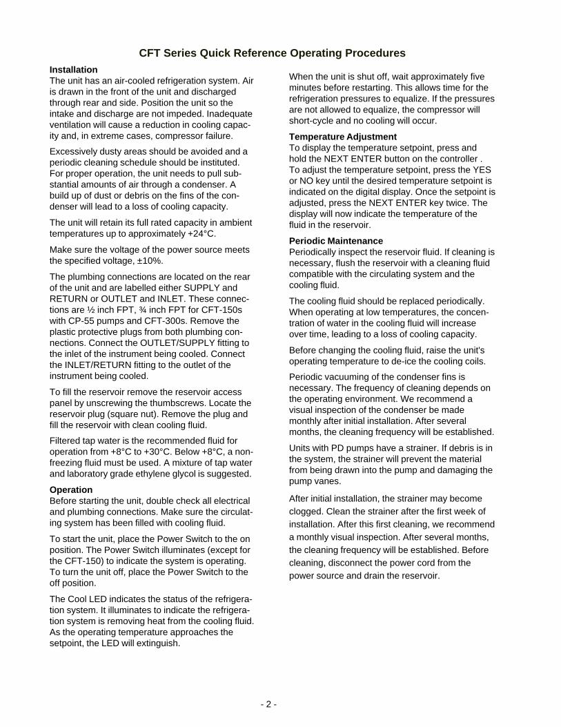
CFT Series Quick Reference Operating Procedures
When the unit is shut off, wait approximately fiveminutes before restarting. This allows time for therefrigeration pressures to equalize. If the pressuresare not allowed to equalize, the compressor willshort-cycle and no cooling will occur.
Temperature AdjustmentTo display the temperature setpoint, press andhold the NEXT ENTER button on the controller .To adjust the temperature setpoint, press the YESor NO key until the desired temperature setpoint isindicated on the digital display. Once the setpoint isadjusted, press the NEXT ENTER key twice. Thedisplay will now indicate the temperature of thefluid in the reservoir.
Periodic MaintenancePeriodically inspect the reservoir fluid. If cleaning isnecessary, flush the reservoir with a cleaning fluidcompatible with the circulating system and thecooling fluid.
The cooling fluid should be replaced periodically.When operating at low temperatures, the concen-tration of water in the cooling fluid will increaseover time, leading to a loss of cooling capacity.
Before changing the cooling fluid, raise the unit'soperating temperature to de-ice the cooling coils.
Periodic vacuuming of the condenser fins isnecessary. The frequency of cleaning depends onthe operating environment. We recommend avisual inspection of the condenser be mademonthly after initial installation. After severalmonths, the cleaning frequency will be established.
Units with PD pumps have a strainer. If debris is inthe system, the strainer will prevent the materialfrom being drawn into the pump and damaging thepump vanes.
After initial installation, the strainer may becomeclogged. Clean the strainer after the first week ofinstallation. After this first cleaning, we recommenda monthly visual inspection. After several months,the cleaning frequency will be established. Beforecleaning, disconnect the power cord from thepower source and drain the reservoir.
InstallationThe unit has an air-cooled refrigeration system. Airis drawn in the front of the unit and dischargedthrough rear and side. Position the unit so theintake and discharge are not impeded. Inadequateventilation will cause a reduction in cooling capac-ity and, in extreme cases, compressor failure.
Excessively dusty areas should be avoided and aperiodic cleaning schedule should be instituted.For proper operation, the unit needs to pull sub-stantial amounts of air through a condenser. Abuild up of dust or debris on the fins of the con-denser will lead to a loss of cooling capacity.
The unit will retain its full rated capacity in ambienttemperatures up to approximately +24°C.
Make sure the voltage of the power source meetsthe specified voltage, ±10%.
The plumbing connections are located on the rearof the unit and are labelled either SUPPLY andRETURN or OUTLET and INLET. These connec-tions are ½ inch FPT, ¾ inch FPT for CFT-150swith CP-55 pumps and CFT-300s. Remove theplastic protective plugs from both plumbing con-nections. Connect the OUTLET/SUPPLY fitting tothe inlet of the instrument being cooled. Connectthe INLET/RETURN fitting to the outlet of theinstrument being cooled.
To fill the reservoir remove the reservoir accesspanel by unscrewing the thumbscrews. Locate thereservoir plug (square nut). Remove the plug andfill the reservoir with clean cooling fluid.
Filtered tap water is the recommended fluid foroperation from +8°C to +30°C. Below +8°C, a non-freezing fluid must be used. A mixture of tap waterand laboratory grade ethylene glycol is suggested.
OperationBefore starting the unit, double check all electricaland plumbing connections. Make sure the circulat-ing system has been filled with cooling fluid.
To start the unit, place the Power Switch to the onposition. The Power Switch illuminates (except forthe CFT-150) to indicate the system is operating.To turn the unit off, place the Power Switch to theoff position.
The Cool LED indicates the status of the refrigera-tion system. It illuminates to indicate the refrigera-tion system is removing heat from the cooling fluid.As the operating temperature approaches thesetpoint, the LED will extinguish.
- 3 -
Preface
ComplianceProducts tested and found to be in compliance with the requirements definedin the EMC standards defined by 89/336/EEC as well as Low Voltage Direc-tive (LVD) 73/23/EEC can be identified by the CE label on the rear of the unit.The testing has demonstrated compliance with the following directives:
LVD, 73/23/EEC Complies with UL 3101-1:93
EMC, 89/336/EEC EN 55011, Class A Verification
EN 50082-1:1992IEC 1000-4-2:1995IEC 1000-4-3:1994IEC 1000-4-4:1995
For any additional information refer to the Letter of Compliance that shippedwith the unit (Declaration of Conformity).
UnpackingRetain all cartons and packing material until the unit is operated and found tobe in good condition. If the unit shows external or internal damage, or doesnot operate properly, contact the transportation company and file a damageclaim. Under ICC regulations, this is your responsibility.
If this product has been modified to operate at 0°C or lower, it has beentested with a non-freezing fluid. Although the system has been drained,some residual fluid may remain. This will not hinder your unit's performance.
WarrantyUnits have a warranty against defective parts and workmanship for one fullyear from date of shipment. See back page for more details.
After-sale SupportNESLAB is committed to customer service both during and after the sale. Ifyou have questions concerning the unit operation, contact our Sales Depart-ment. If your unit fails to operate properly, or if you have questions concerningspare parts or Service Contracts, contact our Service Department.
Before calling, please refer to the labels on the rear of the unit to obtain thefollowing information:
- unit BOM number ________________________________
- unit serial number ________________________________
- pump type ______________________________________
- 4 -
Section I Safety
WarningsWarnings are posted throughout the manual. These warnings are desig-nated by an exclamation mark inside an equilateral triangle and text high-lighted in bold. Read and follow these important instructions. Failure toobserve these instructions can result in permanent damage to the unit,significant property damage, or personal injury or death.
Make sure you read and understand all instructions and safety precautionslisted in this manual before installing or operating your unit. If you have anyquestions concerning the operation of your unit or the information in thismanual, please contact our Sales Department (see After-sale Support).
Never place the unit in a location where excessive heat, moisture, orcorrosive materials are present.
The unit construction provides extra protection against the risk ofelectrical shock by grounding appropriate metal parts. The extraprotection may not function unless the power cord is connected to aproperly grounded outlet. It is the user's responsibility to assure aproper ground connection is provided.
Never connect the OUTLET/SUPPLY or INLET/RETURN fitting to yourbuilding water supply or any water pressure source.
Never use flammable or corrosive fluids with this unit. Distilled anddeionized water may be aggressive and cause material corrosion.Please contact NESLAB before subjecting this unit to prolongedexposure to distilled or deionized water.
Do not use automobile anti-freeze. Commercial anti-freeze containssilicates that can damage the pump seals. Use of automobile anti-freeze will void the manufacturer’s warranty.
Do not replace reservoir plug with a non-vented type or damage to thetank may occur.
For personal safety and equipment reliability, the following procedureshould only be performed by a competent technician. Contact ourService Department for assistance (see Preface, After-sale Support).
- 5 -
Additional WarningsIn addition to the specific warnings listed on the previous page the followinggeneral warnings apply to you unit:
Performance of installation, operation, or maintenance proceduresother than those described in this manual may result in a hazardoussituation and may void the manufacturer's warranty.
Transport the unit with care. Sudden jolts or drops can damage therefrigeration lines.
Observe all warning labels.
Never remove warning labels.
Never operate damaged or leaking equipment.
Never operate the unit without cooling fluid in the reservoir.
Always turn off the unit and disconnect the power cord from the powersource before performing any service or maintenance procedures, orbefore moving the unit.
Always empty the reservoir before moving the unit.
Never operate equipment with damaged power cords.
Refer service and repairs to a qualified technician.

- 6 -
Section II General Information
DescriptionThe CFT Recirculating Chiller is designed to provide a continuous supply ofcooling fluid at a constant temperature and volume.
The unit consists of an air-cooled refrigeration system, a sealable reservoir,recirculating pump, and a temperature controller.
Throughout the manual, you will be asked to consult the unit’s serial numberlabel or the pump identification label for specific information. Both labels arelocated on the rear of the unit.
Specifications
Cooling Capacity 1
60Hz50Hz
Temperature Range 2
Temperature Stability 3
Reservoir VolumeGallons
Liters
Refrigerant
0.51.9
1.86.8
CFT-25 CFT-33 CFT-75 CFT-150 CFT-300
±1.0°C
1.14.1
5.621.3
1. Circulating water at 20°C, at 20°C ambient. Cooling capacity will vary depending on fluidtemperature, ambient temperature, and cooling fluid. A PD-1 pump was used in the CFT-25, aPD-2 in the other units.
2. Modified temperature ranges from -15°C to +85°C are available.3. CFT-300 stability determined with 86% heat load.
R22R134a
580 Watts 950 Watts 2100 Watts 4500Watts 10650 Watts475 Watts 1000 Watts 1900 Watts 3735 Watts 9000 Watts
+5°C to +30°C +5°C to +35°C
±0.5°

- 7 -
C
A
B
H
E
1. Dimension A is the height of the unit. The unit width and depth (dimensions B and C) are the case dimensions. Addapproximately 2 inches to include the plumbing connections.
2. Dimension D is the distance from the floor to the bottom of the unit case (height of the castors).3. Dimension E is the distance from the floor to the center of the DRAIN connection (CFT-300 only).4. Dimension F is the distance from the floor of the center of the OUTLET connection.5. Dimension G is the distance from the floor of the center of the INLET connection.6. Dimension H is the distance from the unit's left side to the center of the INLET, OUTLET and DRAIN connections.7. Weights are given in pounds8. Air intake is given in cubic feet per minute.
Unit DimensionsDimension A
Dimension B
Dimension C
Dimension D
Dimension E
Dimension F
Dimension G
Dimension H
Crate Dimensions(H x W x D
Shipping Weight
Air Intake
Electrical RequirementsVolts
Hertz
Phase
Plug
CFT25 CFT33 CFT75 CFT150 CFT300
22 24½ 26½ 36¾ 43
12½ 14¾ 14 7/8 213/8 25½
21 22 24½ 27¾ 28½
2¾ 2½ 2½ 3½ 2¾
NA NA NA NA 29
171/16 18½ 22 32¼ 38¼
201/16 21½ 25 35¼ 41¼
1½ 1 11/8 11/8 1
31x23x28 31x23x32 32x23x40 33x29x42 35x33x56
110 161 181 320 450
280 375 800 1050 2500
115V 115V 208/230V 208/2300V 208/230V
60Hz 60Hz 60Hz 60Hz 60Hz
1 1 1 1 3
NEMA5-15P NEMA5-20P NEMAL6-15P NEMAL6-20P NA
D
F
G
Rev 01/30/97
- 8 -
10
8
6
4
2
A
B
Flow
P
ress
ure
0.7
0.5
0.4
0.3
0.1
Bar PSI
4.0
3.4
2.7
2.0
1.3
0.7
B
P
ress
ure
60
50
40
30
20
10
Bar PSI
1 2 3 4 GPM
3.8 7.5 11.3 15.1 LPMFlow
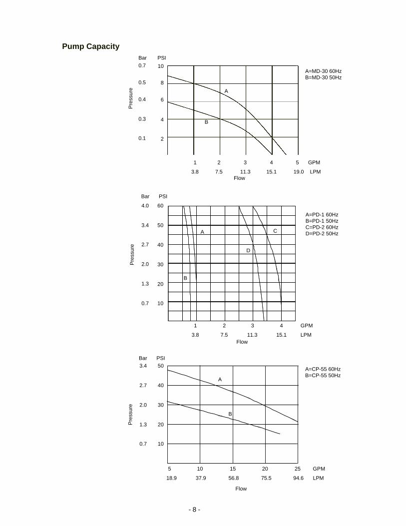
Pump Capacity
1 2 3 4 5 GPM
3.8 7.5 11.3 15.1 19.0 LPM
A=PD-1 60HzB=PD-1 50HzC=PD-2 60HzD=PD-2 50HzA C
D
A=MD-30 60HzB=MD-30 50Hz
A=CP-55 60HzB=CP-55 50Hz
3.4
2.7
2.0
1.3
0.7
B
P
ress
ure
50
40
30
20
10
Bar PSI
A
5 10 15 20 25 GPM
18.9 37.9 56.8 75.5 94.6 LPM
Flow
- 9 -
Section III InstallationSite
The unit should be located in a laboratory or clean industrial environmentwhere ambient temperatures are inside the range of +13°C to +35°C.
Never place the unit in a location where excessive heat, moisture, orcorrosive materials are present.
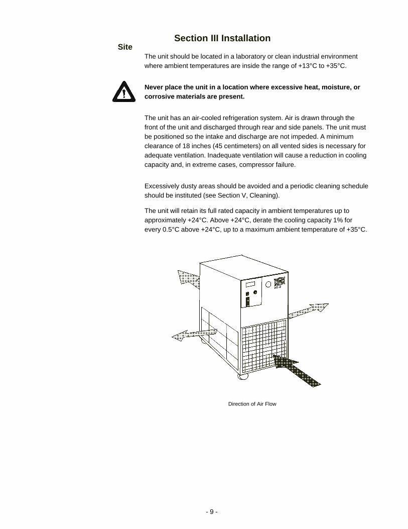
The unit has an air-cooled refrigeration system. Air is drawn through thefront of the unit and discharged through rear and side panels. The unit mustbe positioned so the intake and discharge are not impeded. A minimumclearance of 18 inches (45 centimeters) on all vented sides is necessary foradequate ventilation. Inadequate ventilation will cause a reduction in coolingcapacity and, in extreme cases, compressor failure.
Excessively dusty areas should be avoided and a periodic cleaning scheduleshould be instituted (see Section V, Cleaning).
The unit will retain its full rated capacity in ambient temperatures up toapproximately +24°C. Above +24°C, derate the cooling capacity 1% forevery 0.5°C above +24°C, up to a maximum ambient temperature of +35°C.
Direction of Air Flow

- 10 -
ElectricalRequirements
The unit construction provides extra protection against the risk ofelectrical shock by grounding appropriate metal parts. The extra protec-tion may not function unless the power cord is connected to aproperly grounded outlet. It is the user's responsibility to assure aproper ground connection is provided.
Refer to Section II, Specifications, and to the serial number label on the rearof the unit for the specific electrical requirements of your unit.
The CFT-300 is supplied with a disconnect box. Wire the power connectionsin accordance to local, state and federal electrical codes. Double check allwiring to make sure it is properly connected and protected from the elements.
The CFT-300 is also equipped with a compressor crankcase heater. Thecrankcase heater warms the oil in the compressor and prevents refrigerantfrom mixing with the oil. Before start up, the unit must be connected to itspower source for at least 12 hours. This allows time for the oil to be heatedand separate from the refrigerant.
PlumbingRequirements
Before installing the unit to an instrument that previously used tap water as acooling fluid, flush the instrument several times to remove any rust or scalethat has built up. The manufacturer of the instrument should be able torecommend a cleaning fluid for their equipment.
The plumbing connections are located on the rear of the unit and are labelledOUTLET/SUPPLY and INLET/RETURN. CFT-25 to CFT-150 connections are½ inch FPT, CFT-150s with CP-55 pumps are ¾ inch and CFT-300 connec-tions are ¾ inch FPT.
Remove the plastic protective plugs from both plumbing connections.
Connect the OUTLET/SUPPLY fitting to the inlet of the instrument beingcooled. Connect the INLET/RETURN fitting to the outlet of the instrumentbeing cooled.
Never connect the fittings to your building water supply or any waterpressure source.
Plumbing Connections(Typical)
- 11 -
Two sets of plumbing adapters are included with CFT-25 to CFT-150 units.One set of adapters will accept 3/8 inch ID tubing. The other set will accept½ inch ID tubing. If the unit is being plumbed using flexible tubing, install oneset of adapters in the plumbing ports. To prevent leaking, be sure to wrap thethreads of the adapters with Teflon® sealing tape before installing them in theplumbing ports.
Flexible tubing, if used, should be of heavy wall or reinforced construction.All tubing should be rated to withstand 80 psig at +30°C. Make sure alltubing connections are securely clamped. Avoid running tubing near radia-tors, hot water pipes, etc. If substantial lengths of tubing are necessary,insulation may be required to prevent loss of cooling capacity.
Tubing and insulation are available from NESLAB. Contact our Sales Depart-ment for more information (see Preface, After-sale Support).
It is important to keep the distance between the unit and the instrumentbeing cooled as short as possible, and to use the largest diameter tubingpractical. Tubing should be straight and without bends. If diameter reductionsmust be made, they should be made at the inlet and outlet of theinstrument being cooled, not at the CFT.
If substantial lengths of cooling lines are required, they should be pre-filledwith cooling fluid before connecting them to the unit.
FluidsThe selected fluid must have a viscosity of 50 centistokes or less at thelowest operating temperature.
Never use flammable or corrosive fluids with this unit. Highly distilledand deionized water may be aggressive and cause material corrosion.Please contact NESLAB before subjecting this unit to prolonged expo-sure to highly distilled or deionized water.
Filtered tap water is the recommended fluid for operation from +8°C to +30°C.See Water Quality Standards and Recommendations on the next page.
Below +8°C, a non-freezing fluid must be used. A mixture of tap water andlaboratory grade ethylene glycol is suggested.
Do not use automobile anti-freeze. Commercial anti-freeze containssilicates that can damage the pump seals. Use of automobileanti-freeze will void the manufacturer’s warranty.
- 12 -
Water Quality Standardsand Recommendations
Permissible (PPM) Desirable (PPM)
Microbiologicals(algae, bacteria, fungi) 0 0
Inorganic Chemicals
Calcium <40 0.6
Chloride 250 <25
Copper 1.3 1.0
Iron 0.3 <0.1
Lead 0.015 0
Magnesium <12 0.1
Manganese 0.05 <0.03
Nitrates\Nitrites 10 as N 0
Potassium <20 0.3
Silicate 25 <1.0
Sodium <20 0.3
Sulfate 250 <50
Hardness 17 <0.05
Total Dissolved Solids 50 10
Other Parameters
pH 6.5-8.5 7-8
Resistivity 0.01* 0.05-0.1*
* Megohm-Cm (Compensated at 25°C)
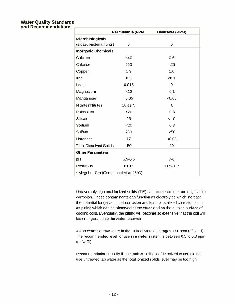
Unfavorably high total ionized solids (TIS) can accelerate the rate of galvaniccorrosion. These contaminants can function as electrolytes which increasethe potential for galvanic cell corrosion and lead to localized corrosion suchas pitting which can be observed at the studs and on the outside surface ofcooling coils. Eventually, the pitting will become so extensive that the coil willleak refrigerant into the water reservoir.
As an example, raw water in the United States averages 171 ppm (of NaCl).The recommended level for use in a water system is between 0.5 to 5.0 ppm(of NaCl).
Recommendation: Initially fill the tank with distilled/deionized water. Do notuse untreated tap water as the total ionized solids level may be too high.
- 13 -
Res
istiv
ity (
meg
ohm
-cm
@ 2
5°C
) Not Recommended, Increasingly
Corrosive
Operations with Stainless Steel Systems
Operations withMixed MetalsCopper/Brass/Stainless Steel CONSULT MATERIALS ENGINEER
10 20 30 40 50 60 70 80
18.30
15.00
10.00
3.00
1.00
0.10
0.05
Water Quality Considerations
Temperature °C
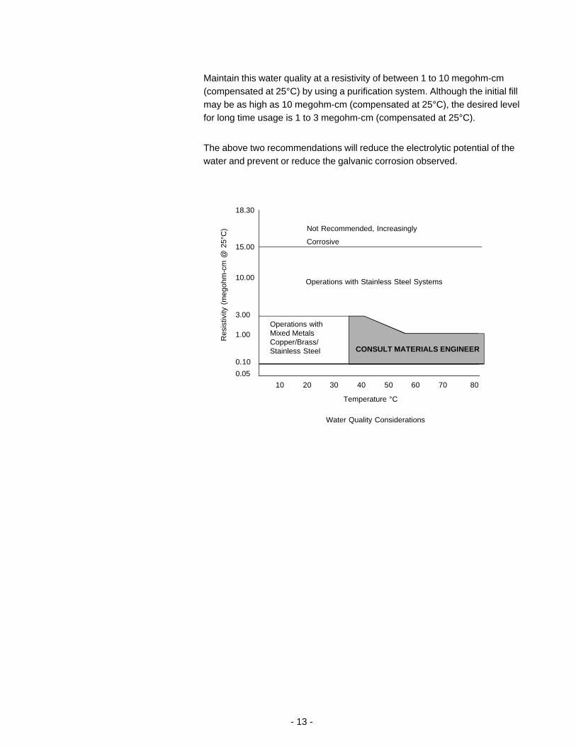
Maintain this water quality at a resistivity of between 1 to 10 megohm-cm(compensated at 25°C) by using a purification system. Although the initial fillmay be as high as 10 megohm-cm (compensated at 25°C), the desired levelfor long time usage is 1 to 3 megohm-cm (compensated at 25°C).
The above two recommendations will reduce the electrolytic potential of thewater and prevent or reduce the galvanic corrosion observed.
- 14 -
Reservoir filling locations (Typical)
Thumbscrew
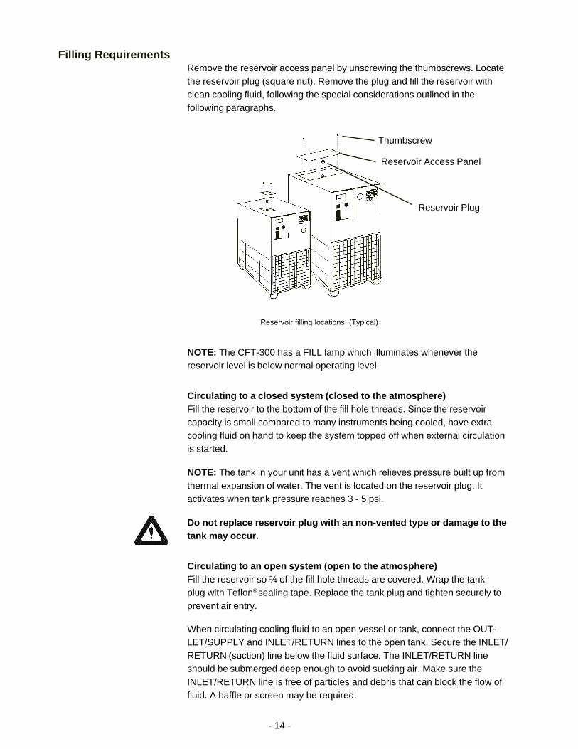
Filling RequirementsRemove the reservoir access panel by unscrewing the thumbscrews. Locatethe reservoir plug (square nut). Remove the plug and fill the reservoir withclean cooling fluid, following the special considerations outlined in thefollowing paragraphs.
NOTE: The CFT-300 has a FILL lamp which illuminates whenever thereservoir level is below normal operating level.
Circulating to a closed system (closed to the atmosphere)Fill the reservoir to the bottom of the fill hole threads. Since the reservoircapacity is small compared to many instruments being cooled, have extracooling fluid on hand to keep the system topped off when external circulationis started.
NOTE: The tank in your unit has a vent which relieves pressure built up fromthermal expansion of water. The vent is located on the reservoir plug. Itactivates when tank pressure reaches 3 - 5 psi.
Do not replace reservoir plug with an non-vented type or damage to thetank may occur.
Circulating to an open system (open to the atmosphere)Fill the reservoir so ¾ of the fill hole threads are covered. Wrap the tankplug with Teflon® sealing tape. Replace the tank plug and tighten securely toprevent air entry.
When circulating cooling fluid to an open vessel or tank, connect the OUT-LET/SUPPLY and INLET/RETURN lines to the open tank. Secure the INLET/RETURN (suction) line below the fluid surface. The INLET/RETURN lineshould be submerged deep enough to avoid sucking air. Make sure theINLET/RETURN line is free of particles and debris that can block the flow offluid. A baffle or screen may be required.
Reservoir Access Panel
Reservoir Plug

- 15 -
Section IV Operation
Start UpBefore starting the unit, double check all electrical and plumbing connectionsand make sure the circulating system (the CFT, the instrument being cooled,and the tubing that connects them) has been properly filled with cooling fluid.To start the unit, place the POWER Switch to the on ( I ) position. Therefrigeration system and the recirculation pump will start. The POWER Switchilluminates (except for the CFT-150) to indicate the system is operating. Unitswith PD pumps display the pump operating pressure on the RECIRCULAT-ING PRESSURE gauge.
To turn the unit off, place the POWER Switch to the off ( 0 ) position.
The COOL LED indicates the status of the refrigeration system. It illuminatesto indicate the refrigeration system is removing heat from the cooling fluid. Asthe operating temperature approaches the temperature setpoint, the LED willextinguish.
The IDLE LED indicates the unit is in a hot-gas-bypass mode of operation. Asthe operating temperature approaches the temperature setpoint, the COOLand IDLE LEDs cycle to indicate the approximate duty cycle of the unit.
When the unit is shut off, wait approximately five minutes before restarting.This allows time for the refrigeration pressures to equalize. If the pressuresare not allowed to equalize, the compressor will short-cycle (clicking sound)and no cooling will occur.
Digital Temperature Controller
COOL
IDLE
YE S NO
NESLAB Instruments
NE XTEN TER
°C
- 16 -
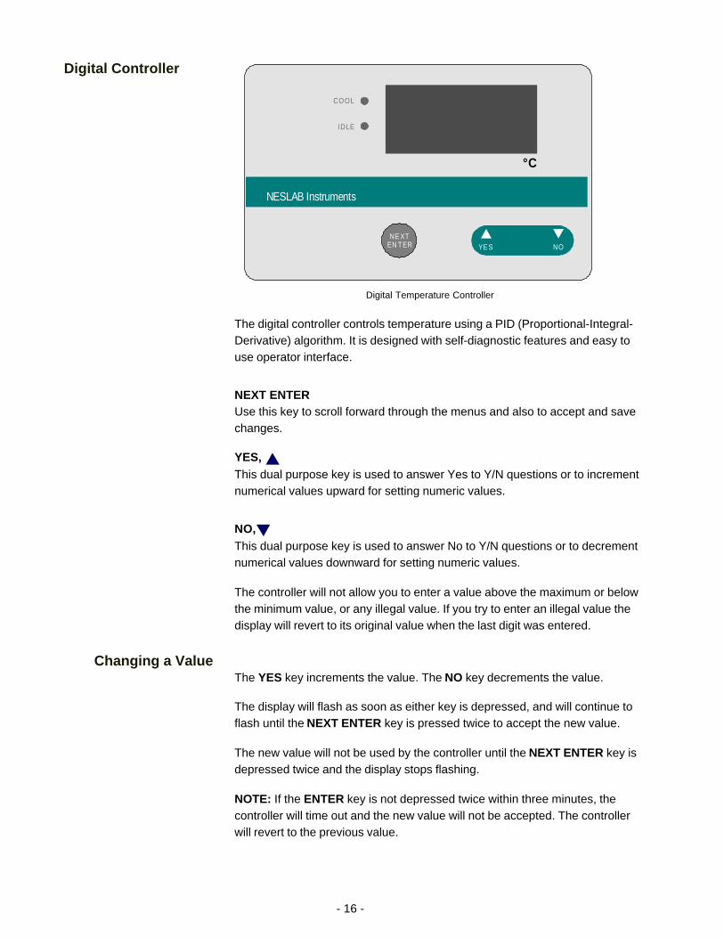
Digital Controller
The digital controller controls temperature using a PID (Proportional-Integral-Derivative) algorithm. It is designed with self-diagnostic features and easy touse operator interface.
NEXT ENTERUse this key to scroll forward through the menus and also to accept and savechanges.
YES, This dual purpose key is used to answer Yes to Y/N questions or to incrementnumerical values upward for setting numeric values.
NO,This dual purpose key is used to answer No to Y/N questions or to decrementnumerical values downward for setting numeric values.
The controller will not allow you to enter a value above the maximum or belowthe minimum value, or any illegal value. If you try to enter an illegal value thedisplay will revert to its original value when the last digit was entered.
Changing a ValueThe YES key increments the value. The NO key decrements the value.
The display will flash as soon as either key is depressed, and will continue toflash until the NEXT ENTER key is pressed twice to accept the new value.
The new value will not be used by the controller until the NEXT ENTER key isdepressed twice and the display stops flashing.
NOTE: If the ENTER key is not depressed twice within three minutes, thecontroller will time out and the new value will not be accepted. The controllerwill revert to the previous value.
Digital Temperature Controller
COOL
IDLE
YE S NO
NESLAB Instruments
NE XTEN TER
°C

- 17 -
The controller will not allow you to enter a value above the unit's maximumtemperature range or below the minimum temperature range. If you try toenter an illegal value outside the range, the display will revert to its originalvalue.
Controller DisplaysAn alphanumeric display presents numeric readings of various operatingconditions within the unit. Display function is selected by pressing the appro-priate keys to move through a menu of available information.
The controller has several loops. The Operator's Loop displays the reservoirtemperature and is used to change the setpoint. The Setup Loop is used toadjust the controller's PID parameters. The Setup Loop can be accessed fromthe Operator's Loop by pressing and holding the key combinations shown in thefigure below.
NOTE: If altering any settings in the Setup Loop, should you desire to returnto the temperature display and abort any changes, keep pressing the NEXTENTER until the display reads Stor , then press NO.
Operator's LoopWhen the controller is first powered up it enters the Operator's Loop, displayingthe reservoir fluid temperature. Press the NEXT ENTER key to view thesetpoint.
SP displays the controller setpoint. The display will flash between SP and theactual setpoint number. Use the YES/NO keys to change the setpoint value.Once the desired setpoint is displayed, press the NEXT ENTER key twice.
Operator's Loop
XXX .X
SP
N O
HO LDGO TOSETU PLO OP
N E X TE N T E R
N E X TE N T E R
N E X TE N T E R
N E X TE N T E R
N E X TE N T E R
- 18 -
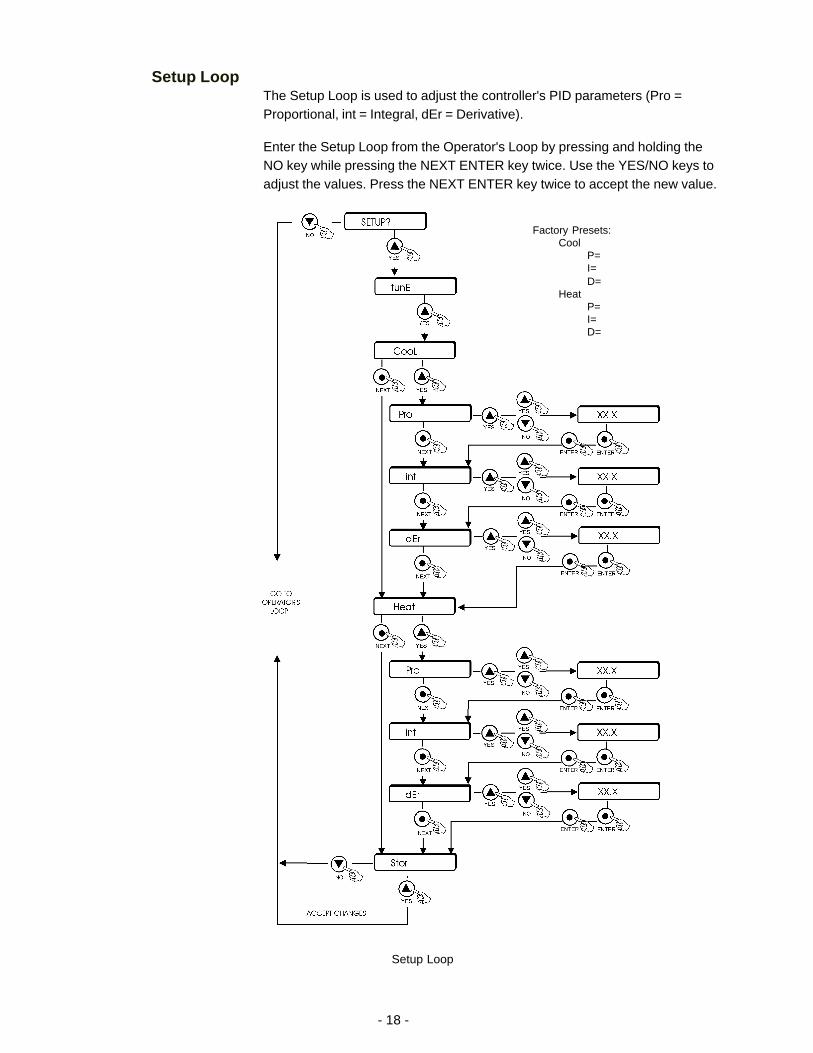
Setup LoopThe Setup Loop is used to adjust the controller's PID parameters (Pro =Proportional, int = Integral, dEr = Derivative).
Enter the Setup Loop from the Operator's Loop by pressing and holding theNO key while pressing the NEXT ENTER key twice. Use the YES/NO keys toadjust the values. Press the NEXT ENTER key twice to accept the new value.
Setup Loop
Factory Presets:Cool
P=I=D=
HeatP=I=D=

- 19 -
Pressure Relief ValveUnits with PD pumps have a pressure relief valve which establishes themaximum operating pressure of the unit. If the pressure of the fluid leavingthe pump exceeds the valve setting, the relief valve will bypass the fluid withinthe unit to relieve the pressure. The relief valve does not determine the actualoperating pressure; the operating pressure is determined by the back pres-sure of the system.
If an adjustment is necessary, contact our Customer Service Department.
High TemperatureCutout (Optional)
The High Temperature Cutout (HTC) is designed to shut down the unit in theevent the temperature of the fluid in the reservoir exceeds the HTC setting.The HTC is normally located on the rear of the unit.
NOTE: The HTC temperature scale is in °F.
CFT-300 High/LowPressure Cutouts
CFT-300 units are equipped with high and low refrigeration pressure cutouts.Should either cutout activate the unit will shut down.
The High Pressure Cutout (HPC) activates if there is a blockage in therefrigeration lines or if the refrigerant temperature becomes too hot. The HPCis factory preset at 400psi.
The Low Pressure Cutout (LPC) activates if there is a leak in the refrigerationlines. THE LPC is factory preset at 4psi.
Both cutouts are located inside the case behind the rear panel. Once thecause of the shut down has been determined and corrected, manuallydepress the white button on the applicable cutout. If a "click" is not heardwhen depressing the button, the cutout was not activated and the unit shutdown for another reason.
CFT-150 HighPressure Cutout
Some CFT-150 units are equipped with High Pressure Cutouts (HPC).Should the HPC activate the unit will shut down.
The HPC activates if there is a blockage in the refrigeration lines or if therefrigerant temperature becomes too hot. The HPC is factory preset at400psi.
The cutout is located inside the case behind the rear panel. Once the causeof the shut down has been determined and corrected, manually depress thewhite button on the applicable cutout. If a "click" is not heard when depressingthe button, the cutout was not activated and the unit shut down for anotherreason.
- 20 -
External PressureRegulator (Optional)
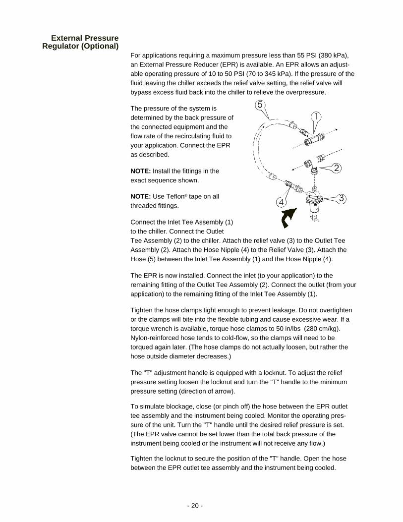
For applications requiring a maximum pressure less than 55 PSI (380 kPa),an External Pressure Reducer (EPR) is available. An EPR allows an adjust-able operating pressure of 10 to 50 PSI (70 to 345 kPa). If the pressure of thefluid leaving the chiller exceeds the relief valve setting, the relief valve willbypass excess fluid back into the chiller to relieve the overpressure.
The pressure of the system isdetermined by the back pressure ofthe connected equipment and theflow rate of the recirculating fluid toyour application. Connect the EPRas described.
NOTE: Install the fittings in theexact sequence shown.
NOTE: Use Teflon® tape on allthreaded fittings.
Connect the Inlet Tee Assembly (1)to the chiller. Connect the OutletTee Assembly (2) to the chiller. Attach the relief valve (3) to the Outlet TeeAssembly (2). Attach the Hose Nipple (4) to the Relief Valve (3). Attach theHose (5) between the Inlet Tee Assembly (1) and the Hose Nipple (4).
The EPR is now installed. Connect the inlet (to your application) to theremaining fitting of the Outlet Tee Assembly (2). Connect the outlet (from yourapplication) to the remaining fitting of the Inlet Tee Assembly (1).
Tighten the hose clamps tight enough to prevent leakage. Do not overtightenor the clamps will bite into the flexible tubing and cause excessive wear. If atorque wrench is available, torque hose clamps to 50 in/lbs (280 cm/kg).Nylon-reinforced hose tends to cold-flow, so the clamps will need to betorqued again later. (The hose clamps do not actually loosen, but rather thehose outside diameter decreases.)
The "T" adjustment handle is equipped with a locknut. To adjust the reliefpressure setting loosen the locknut and turn the "T" handle to the minimumpressure setting (direction of arrow).
To simulate blockage, close (or pinch off) the hose between the EPR outlettee assembly and the instrument being cooled. Monitor the operating pres-sure of the unit. Turn the "T" handle until the desired relief pressure is set.(The EPR valve cannot be set lower than the total back pressure of theinstrument being cooled or the instrument will not receive any flow.)
Tighten the locknut to secure the position of the "T" handle. Open the hosebetween the EPR outlet tee assembly and the instrument being cooled.

- 21 -
Heater Package(Optional)
Heaters are controlled by a switch on the temperature controller. The heateritself is accessible through the small service panel on the rear of the unit.
These units also have a Low Level indicator. The indicator illuminates if thefluid level in the reservoir drops below proper operating level.
Illustration A shows the desired fluid level for normal operation.
Should the reservoir be filled as shown in illustration B, units designed tooperate at high-end temperatures (near boiling) may cause air in the reservoirto become trapped. The air can be vented by slightly tilting the unit forward onits front castors.
Any fluid venting from the reservoir will drain through a hose which feeds to asmall hole in the bottom of the unit.
Do not used silicon-based fluids with units designed to operate at hightemperatures. These type fluids will damage the hoses and pump seal.
Fluid Level Fluid Level
Illustration A Illustration B
- 22 -
Section V Maintenance and Service
For personal safety and equipment reliability, the following procedureshould only be performed by a qualified technician. Contact ourService Department for assistance (see Preface, After-sale Support).
Service ContractsNESLAB offers on-site Service Contracts that are designed to provideextended life and minimal down-time for your unit. For more information,contact our Service Department (see Preface, After-sale Support).
Draining theReservoir
The CFT-300 is equipped with a ½ inch FPT DRAIN fitting located on the rearof the unit.
To drain the CFT-25 to CFT-150 reservoirs we recommend the use of awet/dry vacuum. Remove the reservoir plug and carefully insert the wet/dryvacuum so as not to damage the cooling coils. NOTE: Tilting the unit morethan 45° may allow compressor oil to seep into the suction line.
CleaningReservoirPeriodically inspect the fluid inside the reservoir. If cleaning is necessary,flush the reservoir with a cleaning fluid compatible with the circulating systemand the cooling fluid.
The cooling fluid should be replaced periodically. When operating at lowtemperatures, the concentration of water in the cooling fluid will increaseover time, leading to a loss of cooling capacity.
Before changing the cooling fluid, raise the operating temperature of the unitto de-ice the cooling coils. Refer to Section III, Filling Requirements for in-structions on replacing the cooling fluid.
CondenserFor proper operation, the unit needs to pull substantial amounts of airthrough a condenser. A build up of dust or debris on the fins of the condenserwill lead to a loss of cooling capacity.
The lower front of the unit has a one-piece grille assembly. Gently pry theassembly off with a flathead screwdriver. Use care not to scratch the paint.
Periodic vacuuming of the condenser fins is necessary. The frequency ofcleaning depends on the operating environment. We recommend a visualinspection of the condenser be made monthly after initial installation. Afterseveral months, the frequency of cleaning will be established.
- 23 -
AlgaeTo restrict the growth of algae in the reservoir, it is recommended that thereservoir cover be kept in place and that all circulation lines be opaque. Thiswill eliminate the entrance of light which is required for the growth of mostcommon algae.
NESLAB recommends the use of Chloramine-T, 1 gram per 3.5 liters.
Pump StrainerUnits with PD pumps have a strainer. Refer to the pump label on the rear ofthe unit to identify the type of pump in your unit.
If debris is in the system, the strainer will prevent the material from beingdrawn into the pump and damaging the pump vanes.
After initial installation, the strainer may become clogged with debris andscale. Therefore, the strainer must be cleaned after the first week of installa-tion. After this first cleaning, a monthly visual inspection is recommended.After several months, the frequency of cleaning will be established.
Before cleaning the strainer, disconnect the power cord from the powersource and drain the reservoir.
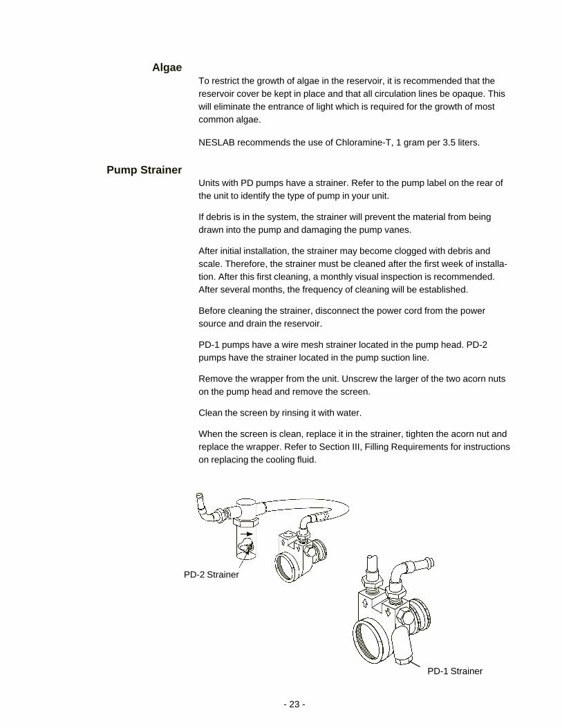
PD-1 pumps have a wire mesh strainer located in the pump head. PD-2pumps have the strainer located in the pump suction line.
Remove the wrapper from the unit. Unscrew the larger of the two acorn nutson the pump head and remove the screen.
Clean the screen by rinsing it with water.
When the screen is clean, replace it in the strainer, tighten the acorn nut andreplace the wrapper. Refer to Section III, Filling Requirements for instructionson replacing the cooling fluid.
PD-2 Strainer
PD-1 Strainer

- 24 -
Duty Cycle Oiling Frequency
Continuous Once every year
Intermittent Once every 2 years
Occasional Once every 5 years
Fill Holes (Typical)
HosesThe unit's internal and external hoses and clamps should be inspected andtightened on at least a semiannual basis.
Suction Discharge PressureSpeed Check
Unit Pump Refrigerant Suction PSIG Discharge PSIG Speed °C/Min
CFT-25 PD-1 R134a 36 -38 160 - 170 4.8
CFT-25 MD-30 R134a 25 - 28 145 -160 4.0
CFT-33 PD1/2 R134a 42 - 45 180 - 200 3.0
CFT-75 PD1/2 R134a 37 - 41 170 -185 4.6
CFT-150 PD2 R22 70 270 2.8
CFT-300 PD2 R22 88 - 94 265 - 280 6.8
CFT-300 CP-55 R22 85 - 90 268 - 280 6.8
Standard temperature 60 Hertz units, derate 17% for 50 Hertz Units. +20°C fluid temperature,unit in the COOL mode, +20°C ambient. 100% water in the reservoir. Wrapper removed.
Pump Motor LubricationPD pump motors require periodic lubrication. Refer to the pump label on therear of the unit to identify the type of pump in your unit.
PD pumps use sleeve type bearings with large reservoirs. Oiling instructionsare generally posted on each motor. In the absence of instructions, addapproximately 30 to 35 drops of SAE 20 non-detergent oil to each bearing onthe following schedule (SAE 20 = 142 CS viscosity):
- 25 -
Section VI Troubleshooting
Checklist
Unit will not startCheck the line cord, make sure it is plugged in.
Check the voltage of the power source. Make sure it is within the ratedvoltage of the unit, ±10%.
Check that the Power Switch/Circuit Breaker has not tripped.
Check the setting on the optional High Temperature Cutout.
CFT-300 units are equipped with high and low pressure switches. If eitherswitch activates the unit will shut down. Once the cause has been determinedyou have to manually reset the switch. The switches are located behind therear panel, see Section IV, Operation.
Unit will not circulate fluidCheck the reservoir level. Fill, if necessary.
Make sure the pump has been purged.
Check the pressure gauge (units with PD pumps). If the reading is 60psig, check the instrument being cooled for restrictions in the cooling line.
Check the pump strainer (units with PD pumps). A clogged strainer canstarve the pump.
Inadequate temperature controlIf the temperature continues to rise, make sure the heat load of theinstrument being cooled does not exceed the rated specification, seeSection II, Specifications.
Make sure the air intake and discharge are not impeded and the ambienttemperature does not exceed +35°C.
Make sure the condenser is free of dust and debris, see Section VI,Cleaning.
If the compressor short-cycles (a clicking sound), check the line voltage.It should be within the 10% of the specified voltage. Wait 5 minutesbefore restarting the unit.
Service AssistanceIf, after following these troubleshooting steps, your unit fails to operateproperly, contact our Service Department for assistance (see Preface, After-sale Support). Before calling, please refer to the serial number label on therear of the unit to obtain the following information:
- unit BOM number- unit serial number- voltage of unit- voltage of power source
- 26 -
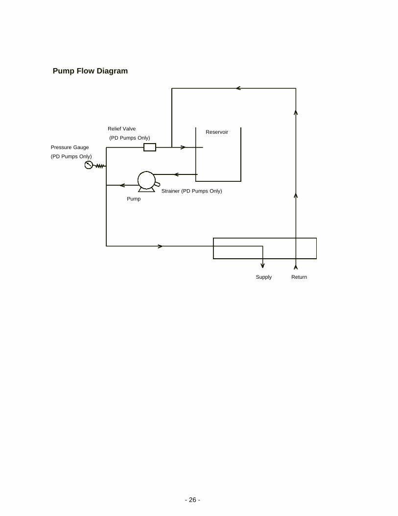
Pump Flow Diagram
Supply Return
Pump
Strainer (PD Pumps Only)
Relief Valve
(PD Pumps Only)
Pressure Gauge
(PD Pumps Only)
Reservoir
- 27 -
WARRANTY
NESLAB Instruments, Inc. warrants for 12 months from date of shipment any NESLAB unit according to thefollowing terms.
Any part of the unit manufactured or supplied by NESLAB and found in the reasonable judgment of NESLABto be defective in material or workmanship will be repaired at an authorized NESLAB Repair Depot withoutcharge for parts or labor. The unit, including any defective part must be returned to an authorized NESLABRepair Depot within the warranty period. The expense of returning the unit to the authorized NESLAB RepairDepot for warranty service will be paid for by the buyer. NESLAB’s responsibility in respect to warranty claimsis limited to performing the required repairs or replacements, and no claim of breach of warranty shall because for cancellation or recision of the contract of sales of any unit.
With respect to units that qualify for field service repairs, NESLAB’s responsibility is limited to the componentparts necessary for the repair and the labor that is required on site to perform the repair. Any travel labor ormileage charges are the financial responsibility of the buyer.
The buyer shall be responsible for any evaluation or warranty service call (including labor charges) if nodefects are found with the NESLAB product.
This warranty does not cover any unit that has been subject to misuse, neglect, or accident. This warrantydoes not apply to any damage to the unit that is the result of improper installation or maintenance, or to anyunit that has been operated or maintained in any way contrary to the operating or maintenance instructionsspecified in NESLAB’s Instruction and Operation Manual. This warranty does not cover any unit that has beenaltered or modified so as to change its intended use.
In addition, this warranty does not extend to repairs made by the use of parts, accessories, or fluids which areeither incompatible with the unit or adversely affect its operation, performance, or durability.
NESLAB reserves the right to change or improve the design of any unit without assuming any obligation tomodify any unit previously manufactured.
THE FOREGOING EXPRESS WARRANTY IS IN LIEU OF ALL OTHER WARRANTIES, EXPRESSED ORIMPLIED, INCLUDING BUT NOT LIMITED TO WARRANTIES OR MERCHANTABILITY AND FITNESS FORA PARTICULAR PURPOSE.
NESLAB’S OBLIGATION UNDER THIS WARRANTY IS STRICTLY AND EXCLUSIVELY LIMITED TO THEREPAIR OR REPLACEMENT OF DEFECTIVE COMPONENT PARTS AND NESLAB DOES NOT ASSUMEOR AUTHORIZE ANYONE TO ASSUME FOR IT ANY OTHER OBLIGATION.
NESLAB ASSUMES NO RESPONSIBILITY FOR INCIDENTAL, CONSEQUENTIAL, OR OTHER DAMAGESINCLUDING, BUT NOT LIMITED TO LOSS OR DAMAGE TO PROPERTY, LOSS OF PROFITS OR REV-ENUE, LOSS OF THE UNIT, LOSS OF TIME, OR INCONVENIENCE.
This warranty applies to units sold in the United States. Any units sold elsewhere are warranted by the affiliatedmarketing company of NESLAB Instruments, Inc. This warranty and all matters arising pursuant to it shall begoverned by the law of the State of New Hampshire, United States. All legal actions brought in relation heretoshall be filed in the appropriate state or federal courts in New Hampshire, unless waived by NESLAB.