Embed Size (px)
Citation preview
American Institute of Aeronautics and Astronautics
1
Thermal Deformation of Very Slender Triangular Rollable
and Collapsible Booms
Olive R. Stohlman1
NASA Langley Research Center, Hampton, VA, 23666, USA
Erik R. Loper2
NASA Marshall Space Flight Center, Huntsville, AL, 35812, USA
Metallic triangular rollable and collapsible (TRAC) booms have deployed two Cubesat-
based solar sails in low Earth orbit, making TRAC booms the most popular solar sail
deployment method in practice. This paper presents some concerns and solutions surrounding
the behavior of these booms in the space thermal environment. A 3.5-cm-tall, 4-meter-long
TRAC boom of Elgiloy cobalt alloy, when exposed to direct sunlight in a 1 AU deep space
environment, has a predicted tip motion of as much as 0.5 meters. Such large thermal
deflections could generate unacceptable distortions in the shape of a supported solar sail,
making attitude control of the solar sail spacecraft difficult or impossible. As a possible means
of mitigating this issue, the thermal distortion behaviors of three alternative material TRAC
booms are investigated and compared with the uncoated Elgiloy baseline boom. A tenfold
decrease in induced curvature is shown to be possible relative to the baseline boom. Potential
thermal distortions of the LightSail-A solar sail TRAC booms are also examined and
compared, although inconclusively, with available on-orbit camera imagery.
I. Introduction
riangular rollable and collapsible (TRAC) booms, originally developed at the US Air Force Research Laboratory
(AFRL), are a class of tape-spring booms characterized by a triangular cross-section [1]. This cross-section can
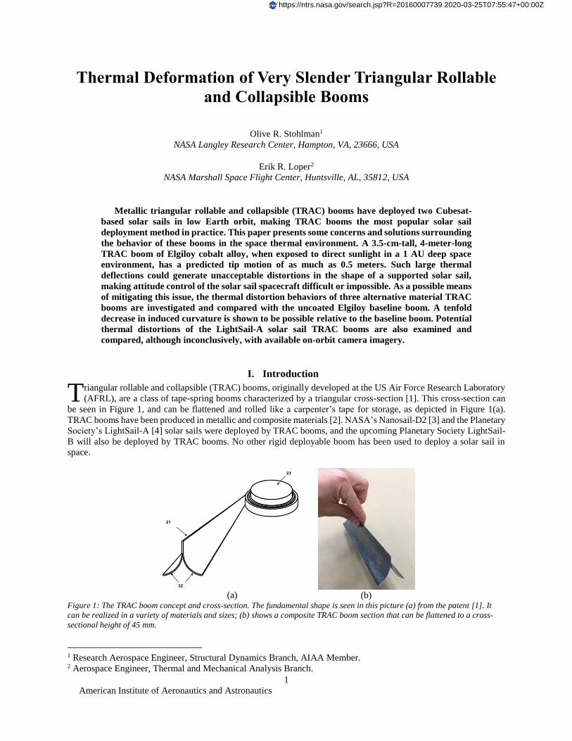
be seen in Figure 1, and can be flattened and rolled like a carpenter’s tape for storage, as depicted in Figure 1(a).
TRAC booms have been produced in metallic and composite materials [2]. NASA’s Nanosail-D2 [3] and the Planetary
Society’s LightSail-A [4] solar sails were deployed by TRAC booms, and the upcoming Planetary Society LightSail-
B will also be deployed by TRAC booms. No other rigid deployable boom has been used to deploy a solar sail in
space.
(a)
(b)
Figure 1: The TRAC boom concept and cross-section. The fundamental shape is seen in this picture (a) from the patent [1]. It
can be realized in a variety of materials and sizes; (b) shows a composite TRAC boom section that can be flattened to a cross-
sectional height of 45 mm.
1 Research Aerospace Engineer, Structural Dynamics Branch, AIAA Member. 2 Aerospace Engineer, Thermal and Mechanical Analysis Branch.
T
https://ntrs.nasa.gov/search.jsp?R=20160007739 2020-03-25T07:55:47+00:00Z
American Institute of Aeronautics and Astronautics
2
TRAC booms are also part of the baseline design for the Near Earth Asteroid (NEA) Scout [5] Cubesat; the content
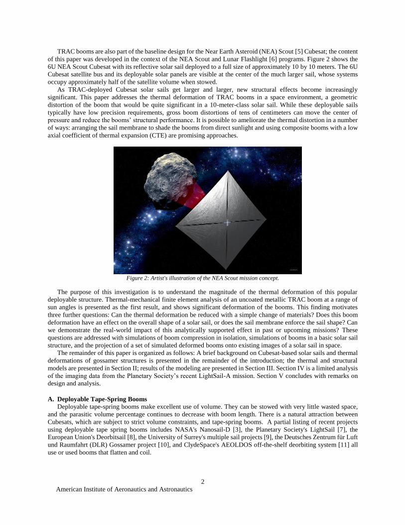
of this paper was developed in the context of the NEA Scout and Lunar Flashlight [6] programs. Figure 2 shows the
6U NEA Scout Cubesat with its reflective solar sail deployed to a full size of approximately 10 by 10 meters. The 6U
Cubesat satellite bus and its deployable solar panels are visible at the center of the much larger sail, whose systems
occupy approximately half of the satellite volume when stowed.
As TRAC-deployed Cubesat solar sails get larger and larger, new structural effects become increasingly
significant. This paper addresses the thermal deformation of TRAC booms in a space environment, a geometric
distortion of the boom that would be quite significant in a 10-meter-class solar sail. While these deployable sails
typically have low precision requirements, gross boom distortions of tens of centimeters can move the center of
pressure and reduce the booms’ structural performance. It is possible to ameliorate the thermal distortion in a number
of ways: arranging the sail membrane to shade the booms from direct sunlight and using composite booms with a low
axial coefficient of thermal expansion (CTE) are promising approaches.
Figure 2: Artist's illustration of the NEA Scout mission concept.
The purpose of this investigation is to understand the magnitude of the thermal deformation of this popular
deployable structure. Thermal-mechanical finite element analysis of an uncoated metallic TRAC boom at a range of
sun angles is presented as the first result, and shows significant deformation of the booms. This finding motivates
three further questions: Can the thermal deformation be reduced with a simple change of materials? Does this boom
deformation have an effect on the overall shape of a solar sail, or does the sail membrane enforce the sail shape? Can
we demonstrate the real-world impact of this analytically supported effect in past or upcoming missions? These
questions are addressed with simulations of boom compression in isolation, simulations of booms in a basic solar sail
structure, and the projection of a set of simulated deformed booms onto existing images of a solar sail in space.
The remainder of this paper is organized as follows: A brief background on Cubesat-based solar sails and thermal
deformations of gossamer structures is presented in the remainder of the introduction; the thermal and structural
models are presented in Section II; results of the modeling are presented in Section III. Section IV is a limited analysis
of the imaging data from the Planetary Society’s recent LightSail-A mission. Section V concludes with remarks on
design and analysis.
A. Deployable Tape-Spring Booms
Deployable tape-spring booms make excellent use of volume. They can be stowed with very little wasted space,
and the parasitic volume percentage continues to decrease with boom length. There is a natural attraction between
Cubesats, which are subject to strict volume constraints, and tape-spring booms. A partial listing of recent projects
using deployable tape spring booms includes NASA's Nanosail-D [3], the Planetary Society's LightSail [7], the
European Union's Deorbitsail [8], the University of Surrey's multiple sail projects [9], the Deutsches Zentrum für Luft
und Raumfahrt (DLR) Gossamer project [10], and ClydeSpace's AEOLDOS off-the-shelf deorbiting system [11] all
use or used booms that flatten and coil.
American Institute of Aeronautics and Astronautics
3
B. The Space Thermal Environment and Large Structures
Extreme temperatures are a common feature in space missions. Gossamer structures, in particular, may experience
thermal deformations that are large enough to be clearly visible to the naked eye, but most are known purely as analysis
results.
Blandino [12] has presented a coupled thermal-structural analysis of Storable Tubular Extendable Member
(STEM) booms, a type of rollable boom with a slit circular cross-section. For large structures, geometry changes may
be large enough that a single thermal analysis is not acceptable, and coupling (or slower sequential iteration) must be
introduced to capture the simultaneous changes in geometry and temperature distribution. The DLR closed-section
lenticular boom has also undergone thermal analysis [10]; both STEM and closed-section lenticular booms benefit
from the low coefficient of thermal expansion of their composite materials in these designs.
A study of the Gravity and Extreme Magnetism Small Explorer (GEMS) telescope boom [13] predicted advantages
to shading the structure with a Kapton “sock;” in the case of this high-precision truss boom, the shape distortion could
be reduced by an order of magnitude by protecting the structure from direct sunlight.
II. Modeling
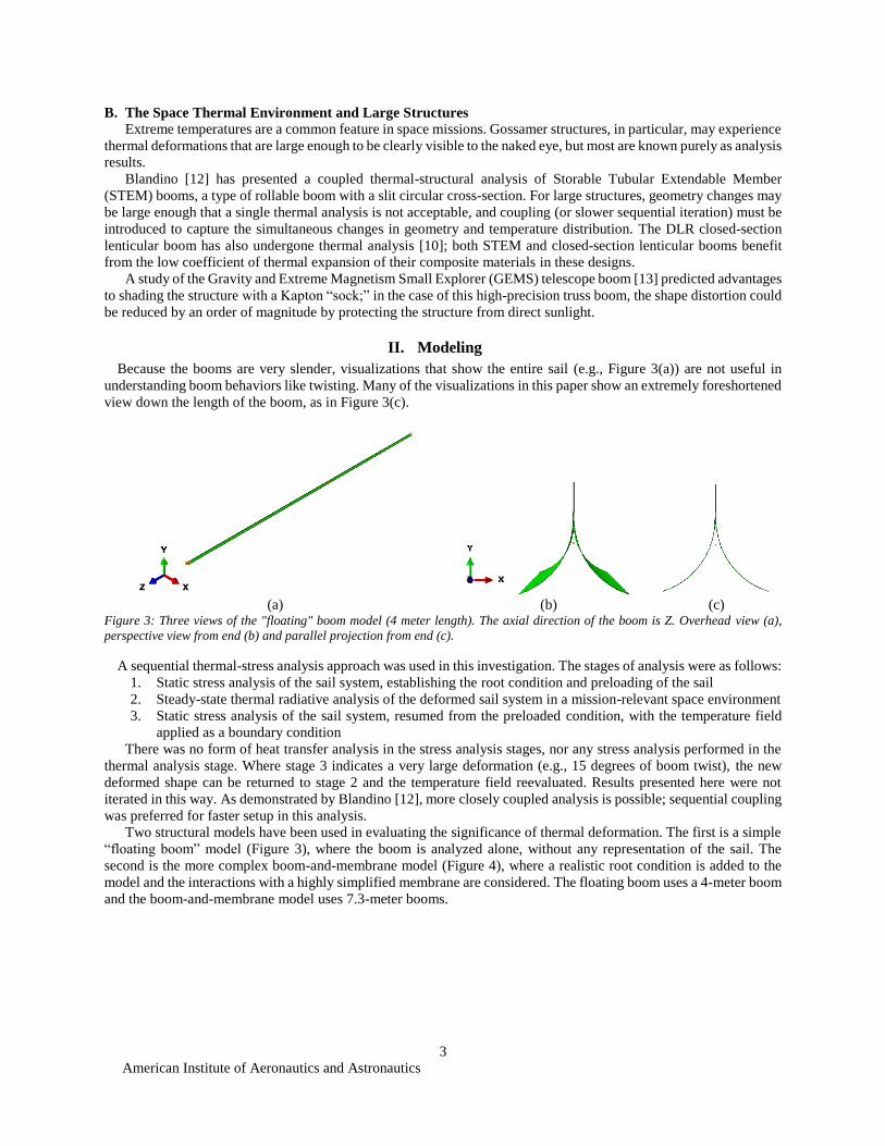
Because the booms are very slender, visualizations that show the entire sail (e.g., Figure 3(a)) are not useful in
understanding boom behaviors like twisting. Many of the visualizations in this paper show an extremely foreshortened
view down the length of the boom, as in Figure 3(c).
(a)
(b)
(c)
Figure 3: Three views of the "floating" boom model (4 meter length). The axial direction of the boom is Z. Overhead view (a),
perspective view from end (b) and parallel projection from end (c).
A sequential thermal-stress analysis approach was used in this investigation. The stages of analysis were as follows:
1. Static stress analysis of the sail system, establishing the root condition and preloading of the sail
2. Steady-state thermal radiative analysis of the deformed sail system in a mission-relevant space environment
3. Static stress analysis of the sail system, resumed from the preloaded condition, with the temperature field
applied as a boundary condition
There was no form of heat transfer analysis in the stress analysis stages, nor any stress analysis performed in the
thermal analysis stage. Where stage 3 indicates a very large deformation (e.g., 15 degrees of boom twist), the new
deformed shape can be returned to stage 2 and the temperature field reevaluated. Results presented here were not
iterated in this way. As demonstrated by Blandino [12], more closely coupled analysis is possible; sequential coupling
was preferred for faster setup in this analysis.
Two structural models have been used in evaluating the significance of thermal deformation. The first is a simple
“floating boom” model (Figure 3), where the boom is analyzed alone, without any representation of the sail. The
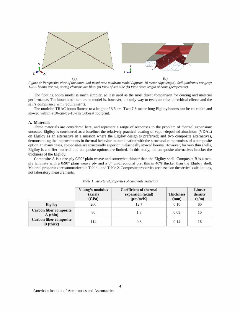
second is the more complex boom-and-membrane model (Figure 4), where a realistic root condition is added to the
model and the interactions with a highly simplified membrane are considered. The floating boom uses a 4-meter boom
and the boom-and-membrane model uses 7.3-meter booms.
American Institute of Aeronautics and Astronautics
4
(a)
(b)
Figure 4: Perspective view of the boom-and-membrane quadrant model (approx. 10 meter edge length). Sail quadrants are grey;
TRAC booms are red; spring elements are blue. (a) View of sun side (b) View down length of boom (perspective)
The floating boom model is much simpler, so it is used as the most direct comparison for coating and material
performance. The boom-and-membrane model is, however, the only way to evaluate mission-critical effects and the
sail’s compliance with requirements.
The modeled TRAC boom flattens to a height of 3.5 cm. Two 7.3-meter-long Elgiloy booms can be co-coiled and
stowed within a 10-cm-by-10-cm Cubesat footprint.
A. Materials
Three materials are considered here, and represent a range of responses to the problem of thermal expansion:
uncoated Elgiloy is considered as a baseline; the relatively practical coating of vapor-deposited aluminum (VDAL)
on Elgiloy as an alternative in a mission where the Elgiloy design is preferred; and two composite alternatives,
demonstrating the improvements in thermal behavior in combination with the structural compromises of a composite
option. In many cases, composites are structurally superior in elastically stowed booms. However, for very thin shells,
Elgiloy is a stiffer material and composite options are limited. In this study, the composite alternatives bracket the
thickness of the Elgiloy.
Composite A is a one-ply 0/90° plain weave and somewhat thinner than the Elgiloy shell. Composite B is a two-
ply laminate with a 0/90° plain weave ply and a 0° unidirectional ply; this is 40% thicker than the Elgiloy shell.
Material properties are summarized in Table 1 and Table 2. Composite properties are based on theoretical calculations,
not laboratory measurements.
Table 1: Structural properties of candidate materials
Young’s modulus
(axial)
(GPa)
Coefficient of thermal
expansion (axial)
(μm/m/K)
Thickness
(mm)
Linear
density
(g/m)
Elgiloy 200 12.7 0.10 60
Carbon fiber composite
A (thin) 80 1.3 0.09 10
Carbon fiber composite
B (thick) 114 0.8 0.14 16
American Institute of Aeronautics and Astronautics
5
Table 2: Thermal properties of candidate materials
Thermal Conductivity
(transverse)
(W/mK)
Density
(kg/m3) Emissivity
Solar
absorptivity
Elgiloy 12.5 8300 0.107 0.43
Vapor deposited
aluminum coating -- -- 0.08 [14] 0.02
Carbon fiber composite
A (thin) 4.3 1580 0.75 [15] 0.92
Carbon fiber composite
B (thick) 3.3 1580 0.75 0.92
B. Thermal Modeling
The thermal environment was created using the Thermal Desktop orbit tool. The environment for the floating
boom cases places a single boom at 1 Astronomical Unit (AU) from the sun. For the boom-and-membrane model, a
position near the southern lunar pole at an altitude of 20 km was used to create the thermal environment. The moon
was modeled with a planet shine of 122.8 °C for the hot side and -233.15 °C for the dark side. Albedo and solar flux
were modeled using an albedo of 0.1, and a solar flux of 1354 W/m2. The orientation of the satellite and the orbit were
defined with two vectors, listed in Table 3.
Table 3: Solar and Planet vector used to define the orientation and location of the lunar flashlight satellite during the science
portion of the Lunar Flashlight mission. The coordinate frame is the same as in Figure 4.
Vector X Y Z
Solar 0.0000 0.7071 -0.7071
Planet 0.0000 -0.6309 -0.7759
The boom was modeled using Thermal Desktop plate elements. The fused web thickness was 0.204 mm and the
legs of the boom were modeled with a thickness of 0.102 mm. The TRAC booms were modeled with the material
properties of Elgiloy and a range of optical properties describing different coatings, including the uncoated option of
heat-treated Elgiloy; the optical properties were measured at Marshall Space Flight Center. Some of the material and
optical properties used in the model are listed in Table 2.
C. Structural Modeling
All structural modeling was performed using Abaqus/Standard [16]. For the floating boom case, a 4-meter boom
was modeled. Each boom comprises 28000 S4 shell elements. The nodes of the root cross-section are constrained in
the three translational degrees of freedom and the nodes of the tip cross-section are constrained as a rigid body. To
evaluate stiffness in compression, the boom was loaded by shortening a connector element between the root and tip
centroid. These centroid nodes are rigidly fixed to the root and tip cross-sections.
The unloaded, thermally distorted shape of the floating boom model can be compared with theory by assuming
linear distribution of temperature across the cross section. This will induce a constant curvature in the boom. The
radius of curvature can be estimated by the following equation:
𝑟𝑙𝑖𝑛𝑒𝑎𝑟 =ℎ
𝛼Δ𝑇
for a boom of height ℎ, coefficient of thermal expansion 𝛼, and temperature differential Δ𝑇. Because of the irregular
shape of the TRAC cross-section and the nonlinear temperature distribution in the cross-section, this is at most a very
approximate estimate of the radius of curvature, but it is useful as an order-of-magnitude estimate. Another possible
simplification of the problem assumes a step distribution of temperature, with half of the cross-section at a low
temperature and half at a high temperature; this step distribution gives a value of 𝑟𝑠𝑡𝑒𝑝 = 2/3 ∙ 𝑟𝑙𝑖𝑛𝑒𝑎𝑟 . These two
values are observed to bound the finite element analysis (FEA) results presented here.
American Institute of Aeronautics and Astronautics
6
All materials are considered to be elastic, and all material properties are taken as constant with respect to
temperature, with the exception of the thermal expansion coefficient of Elgiloy, which is represented as temperature-
dependent. Composites are modeled as orthotropic.
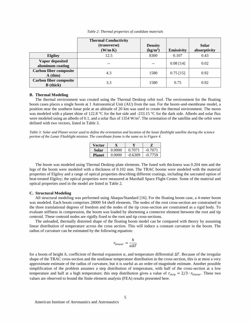
In the boom-and-membrane models, each boom comprises 28000 S4 shell elements, with greater element density
near the root and tip, as shown in Figure 5. Each membrane quadrant is modeled as a single M3D3 element and the
Abaqus *NO COMPRESSION material option is activated.
Figure 5: TRAC boom tip with mesh.
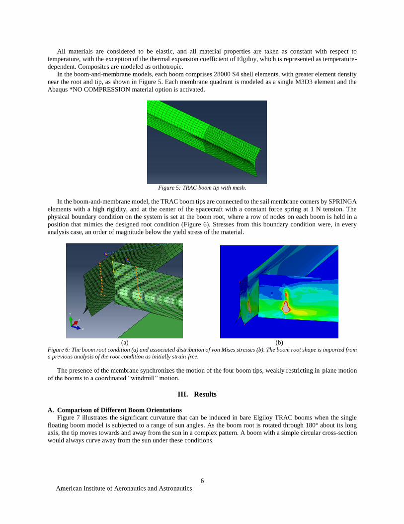
In the boom-and-membrane model, the TRAC boom tips are connected to the sail membrane corners by SPRINGA
elements with a high rigidity, and at the center of the spacecraft with a constant force spring at 1 N tension. The
physical boundary condition on the system is set at the boom root, where a row of nodes on each boom is held in a
position that mimics the designed root condition (Figure 6). Stresses from this boundary condition were, in every
analysis case, an order of magnitude below the yield stress of the material.
(a)
(b)
Figure 6: The boom root condition (a) and associated distribution of von Mises stresses (b). The boom root shape is imported from
a previous analysis of the root condition as initially strain-free.
The presence of the membrane synchronizes the motion of the four boom tips, weakly restricting in-plane motion
of the booms to a coordinated “windmill” motion.
III. Results
A. Comparison of Different Boom Orientations
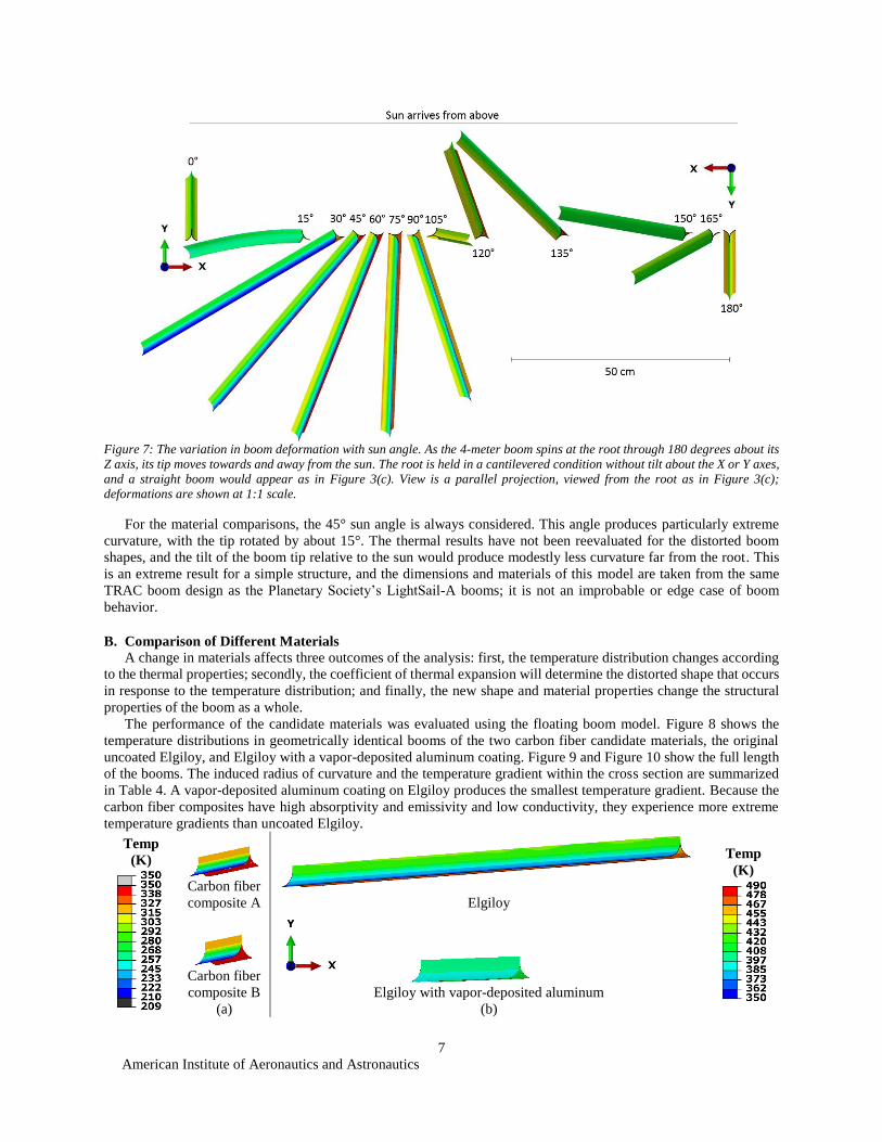
Figure 7 illustrates the significant curvature that can be induced in bare Elgiloy TRAC booms when the single
floating boom model is subjected to a range of sun angles. As the boom root is rotated through 180° about its long
axis, the tip moves towards and away from the sun in a complex pattern. A boom with a simple circular cross-section
would always curve away from the sun under these conditions.
American Institute of Aeronautics and Astronautics
7
Figure 7: The variation in boom deformation with sun angle. As the 4-meter boom spins at the root through 180 degrees about its
Z axis, its tip moves towards and away from the sun. The root is held in a cantilevered condition without tilt about the X or Y axes,
and a straight boom would appear as in Figure 3(c). View is a parallel projection, viewed from the root as in Figure 3(c);
deformations are shown at 1:1 scale.
For the material comparisons, the 45° sun angle is always considered. This angle produces particularly extreme
curvature, with the tip rotated by about 15°. The thermal results have not been reevaluated for the distorted boom
shapes, and the tilt of the boom tip relative to the sun would produce modestly less curvature far from the root. This
is an extreme result for a simple structure, and the dimensions and materials of this model are taken from the same
TRAC boom design as the Planetary Society’s LightSail-A booms; it is not an improbable or edge case of boom
behavior.
B. Comparison of Different Materials
A change in materials affects three outcomes of the analysis: first, the temperature distribution changes according
to the thermal properties; secondly, the coefficient of thermal expansion will determine the distorted shape that occurs
in response to the temperature distribution; and finally, the new shape and material properties change the structural
properties of the boom as a whole.
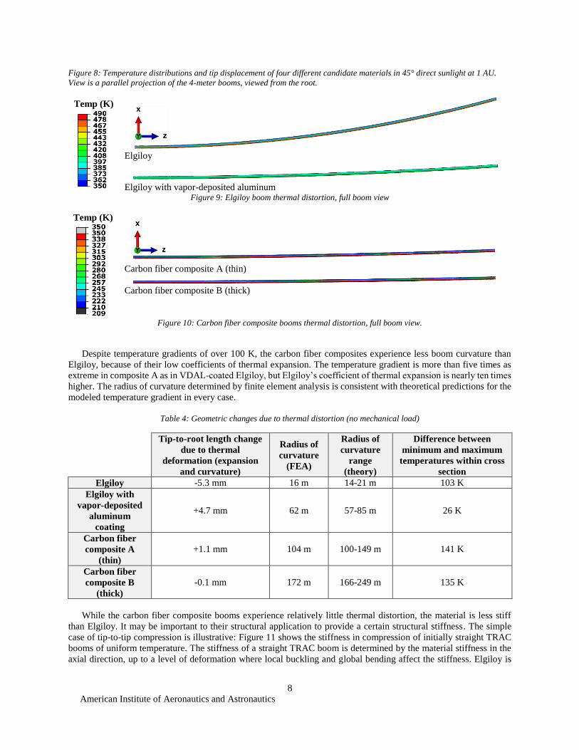
The performance of the candidate materials was evaluated using the floating boom model. Figure 8 shows the
temperature distributions in geometrically identical booms of the two carbon fiber candidate materials, the original
uncoated Elgiloy, and Elgiloy with a vapor-deposited aluminum coating. Figure 9 and Figure 10 show the full length
of the booms. The induced radius of curvature and the temperature gradient within the cross section are summarized
in Table 4. A vapor-deposited aluminum coating on Elgiloy produces the smallest temperature gradient. Because the
carbon fiber composites have high absorptivity and emissivity and low conductivity, they experience more extreme
temperature gradients than uncoated Elgiloy.
Temp
(K)
Carbon fiber
composite A
Elgiloy
Temp
(K)
Carbon fiber
composite B
(a)
Elgiloy with vapor-deposited aluminum
(b)
American Institute of Aeronautics and Astronautics
8
Figure 8: Temperature distributions and tip displacement of four different candidate materials in 45° direct sunlight at 1 AU.
View is a parallel projection of the 4-meter booms, viewed from the root.
Temp (K)
Elgiloy
Elgiloy with vapor-deposited aluminum
Figure 9: Elgiloy boom thermal distortion, full boom view
Temp (K)
Carbon fiber composite A (thin)
Carbon fiber composite B (thick)
Figure 10: Carbon fiber composite booms thermal distortion, full boom view.
Despite temperature gradients of over 100 K, the carbon fiber composites experience less boom curvature than
Elgiloy, because of their low coefficients of thermal expansion. The temperature gradient is more than five times as
extreme in composite A as in VDAL-coated Elgiloy, but Elgiloy’s coefficient of thermal expansion is nearly ten times
higher. The radius of curvature determined by finite element analysis is consistent with theoretical predictions for the
modeled temperature gradient in every case.
Table 4: Geometric changes due to thermal distortion (no mechanical load)
Tip-to-root length change
due to thermal
deformation (expansion
and curvature)
Radius of
curvature
(FEA)
Radius of
curvature
range
(theory)
Difference between
minimum and maximum
temperatures within cross
section
Elgiloy -5.3 mm 16 m 14-21 m 103 K
Elgiloy with
vapor-deposited
aluminum
coating
+4.7 mm 62 m 57-85 m 26 K
Carbon fiber
composite A
(thin)
+1.1 mm 104 m 100-149 m 141 K
Carbon fiber
composite B
(thick)
-0.1 mm 172 m 166-249 m 135 K
While the carbon fiber composite booms experience relatively little thermal distortion, the material is less stiff
than Elgiloy. It may be important to their structural application to provide a certain structural stiffness. The simple
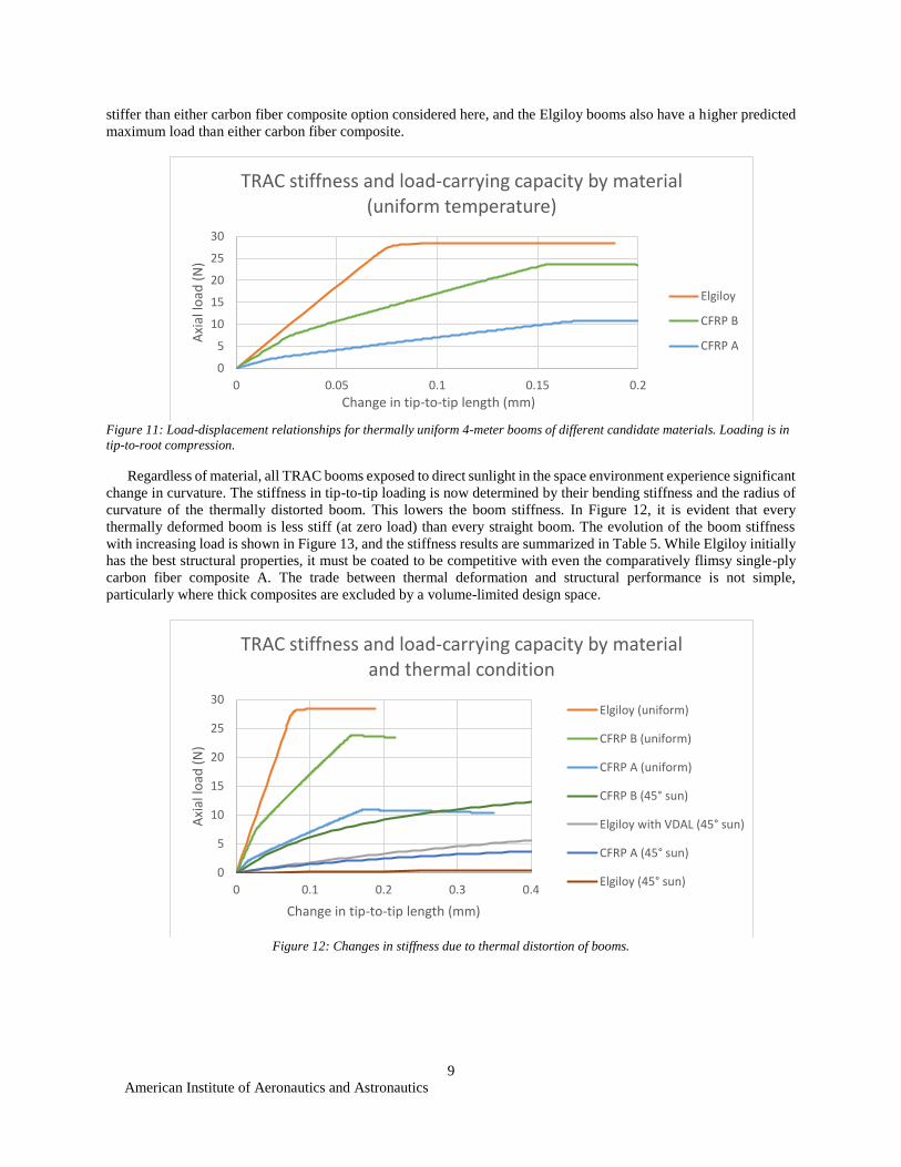
case of tip-to-tip compression is illustrative: Figure 11 shows the stiffness in compression of initially straight TRAC
booms of uniform temperature. The stiffness of a straight TRAC boom is determined by the material stiffness in the
axial direction, up to a level of deformation where local buckling and global bending affect the stiffness. Elgiloy is
American Institute of Aeronautics and Astronautics
9
stiffer than either carbon fiber composite option considered here, and the Elgiloy booms also have a higher predicted
maximum load than either carbon fiber composite.
Figure 11: Load-displacement relationships for thermally uniform 4-meter booms of different candidate materials. Loading is in
tip-to-root compression.
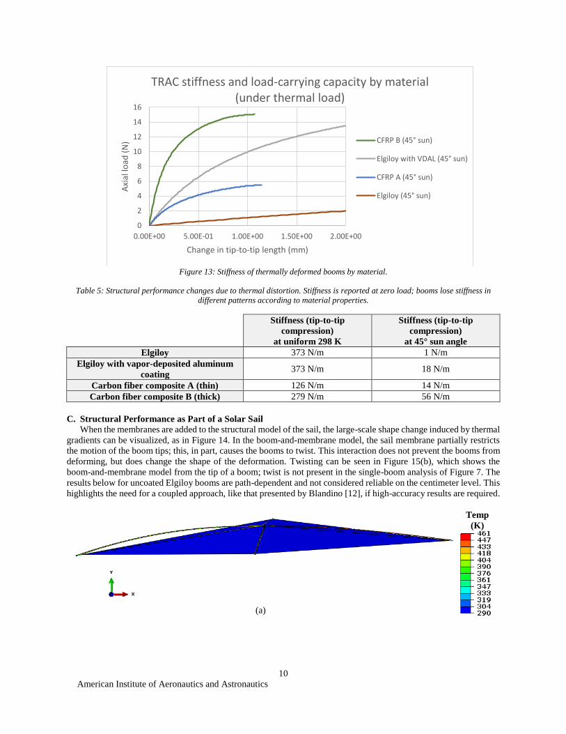
Regardless of material, all TRAC booms exposed to direct sunlight in the space environment experience significant
change in curvature. The stiffness in tip-to-tip loading is now determined by their bending stiffness and the radius of
curvature of the thermally distorted boom. This lowers the boom stiffness. In Figure 12, it is evident that every
thermally deformed boom is less stiff (at zero load) than every straight boom. The evolution of the boom stiffness
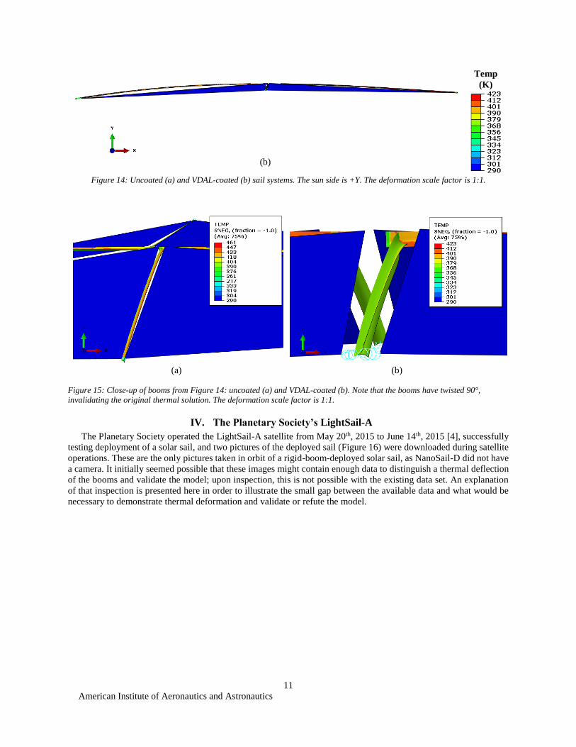
with increasing load is shown in Figure 13, and the stiffness results are summarized in Table 5. While Elgiloy initially
has the best structural properties, it must be coated to be competitive with even the comparatively flimsy single-ply
carbon fiber composite A. The trade between thermal deformation and structural performance is not simple,
particularly where thick composites are excluded by a volume-limited design space.
Figure 12: Changes in stiffness due to thermal distortion of booms.
0
5
10
15
20
25
30
0 0.05 0.1 0.15 0.2
Axi
al lo
ad (
N)
Change in tip-to-tip length (mm)
TRAC stiffness and load-carrying capacity by material (uniform temperature)
Elgiloy
CFRP B
CFRP A
0
5
10
15
20
25
30
0 0.1 0.2 0.3 0.4
Axi
al lo
ad (
N)
Change in tip-to-tip length (mm)
TRAC stiffness and load-carrying capacity by material and thermal condition
Elgiloy (uniform)
CFRP B (uniform)
CFRP A (uniform)
CFRP B (45° sun)
Elgiloy with VDAL (45° sun)
CFRP A (45° sun)
Elgiloy (45° sun)
American Institute of Aeronautics and Astronautics
10
Figure 13: Stiffness of thermally deformed booms by material.
Table 5: Structural performance changes due to thermal distortion. Stiffness is reported at zero load; booms lose stiffness in
different patterns according to material properties.
Stiffness (tip-to-tip
compression)
at uniform 298 K
Stiffness (tip-to-tip
compression)
at 45° sun angle
Elgiloy 373 N/m 1 N/m
Elgiloy with vapor-deposited aluminum
coating 373 N/m 18 N/m
Carbon fiber composite A (thin) 126 N/m 14 N/m
Carbon fiber composite B (thick) 279 N/m 56 N/m
C. Structural Performance as Part of a Solar Sail
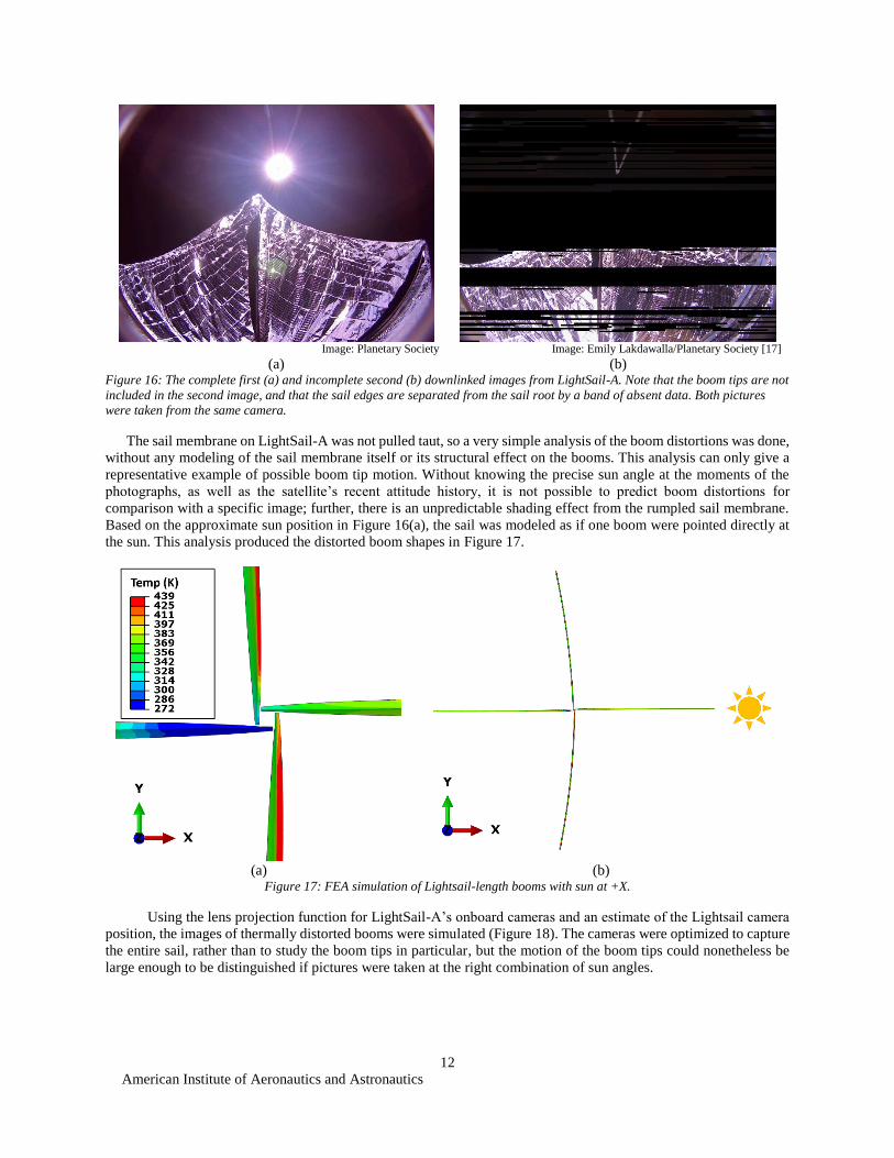
When the membranes are added to the structural model of the sail, the large-scale shape change induced by thermal
gradients can be visualized, as in Figure 14. In the boom-and-membrane model, the sail membrane partially restricts
the motion of the boom tips; this, in part, causes the booms to twist. This interaction does not prevent the booms from
deforming, but does change the shape of the deformation. Twisting can be seen in Figure 15(b), which shows the
boom-and-membrane model from the tip of a boom; twist is not present in the single-boom analysis of Figure 7. The
results below for uncoated Elgiloy booms are path-dependent and not considered reliable on the centimeter level. This
highlights the need for a coupled approach, like that presented by Blandino [12], if high-accuracy results are required.
(a)
Temp
(K)
0
2
4
6
8
10
12
14
16
0.00E+00 5.00E-01 1.00E+00 1.50E+00 2.00E+00
Axi
al lo
ad (
N)
Change in tip-to-tip length (mm)
TRAC stiffness and load-carrying capacity by material (under thermal load)
CFRP B (45° sun)
Elgiloy with VDAL (45° sun)
CFRP A (45° sun)
Elgiloy (45° sun)
American Institute of Aeronautics and Astronautics
11
(b)
Temp
(K)
Figure 14: Uncoated (a) and VDAL-coated (b) sail systems. The sun side is +Y. The deformation scale factor is 1:1.
(a)
(b)
Figure 15: Close-up of booms from Figure 14: uncoated (a) and VDAL-coated (b). Note that the booms have twisted 90°,
invalidating the original thermal solution. The deformation scale factor is 1:1.
IV. The Planetary Society’s LightSail-A
The Planetary Society operated the LightSail-A satellite from May 20th, 2015 to June 14th, 2015 [4], successfully
testing deployment of a solar sail, and two pictures of the deployed sail (Figure 16) were downloaded during satellite
operations. These are the only pictures taken in orbit of a rigid-boom-deployed solar sail, as NanoSail-D did not have
a camera. It initially seemed possible that these images might contain enough data to distinguish a thermal deflection
of the booms and validate the model; upon inspection, this is not possible with the existing data set. An explanation
of that inspection is presented here in order to illustrate the small gap between the available data and what would be
necessary to demonstrate thermal deformation and validate or refute the model.
American Institute of Aeronautics and Astronautics
12
Image: Planetary Society
(a)
Image: Emily Lakdawalla/Planetary Society [17]
(b) Figure 16: The complete first (a) and incomplete second (b) downlinked images from LightSail-A. Note that the boom tips are not
included in the second image, and that the sail edges are separated from the sail root by a band of absent data. Both pictures
were taken from the same camera.
The sail membrane on LightSail-A was not pulled taut, so a very simple analysis of the boom distortions was done,
without any modeling of the sail membrane itself or its structural effect on the booms. This analysis can only give a
representative example of possible boom tip motion. Without knowing the precise sun angle at the moments of the
photographs, as well as the satellite’s recent attitude history, it is not possible to predict boom distortions for
comparison with a specific image; further, there is an unpredictable shading effect from the rumpled sail membrane.
Based on the approximate sun position in Figure 16(a), the sail was modeled as if one boom were pointed directly at
the sun. This analysis produced the distorted boom shapes in Figure 17.
(a)
(b)
Figure 17: FEA simulation of Lightsail-length booms with sun at +X.
Using the lens projection function for LightSail-A’s onboard cameras and an estimate of the Lightsail camera
position, the images of thermally distorted booms were simulated (Figure 18). The cameras were optimized to capture
the entire sail, rather than to study the boom tips in particular, but the motion of the boom tips could nonetheless be
large enough to be distinguished if pictures were taken at the right combination of sun angles.
American Institute of Aeronautics and Astronautics
13
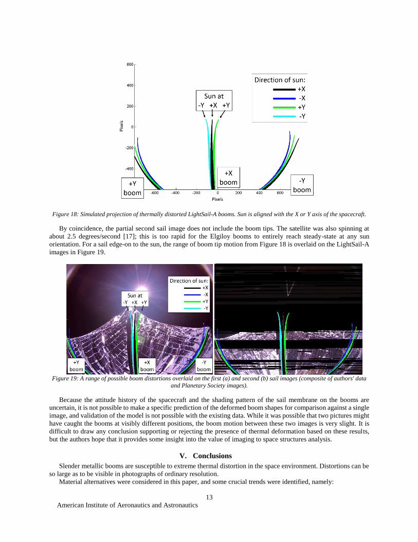
Figure 18: Simulated projection of thermally distorted LightSail-A booms. Sun is aligned with the X or Y axis of the spacecraft.
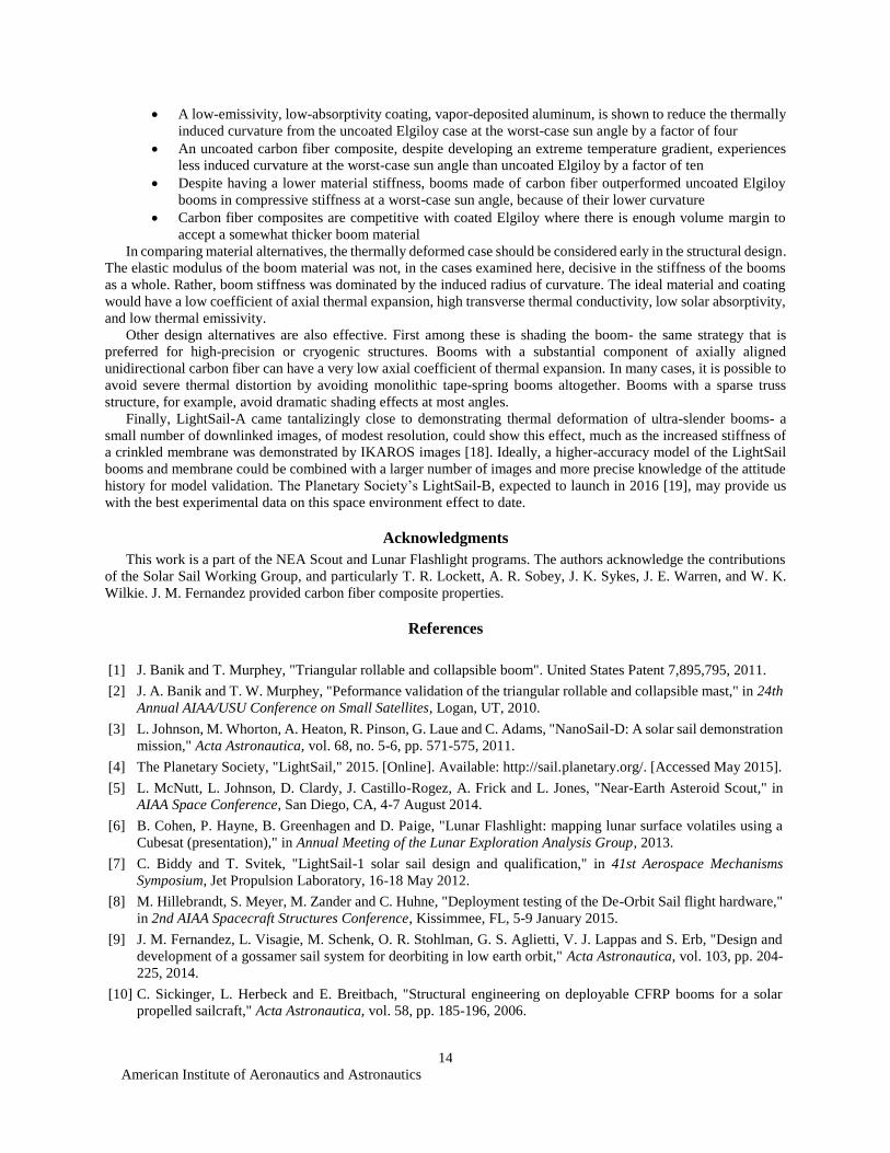
By coincidence, the partial second sail image does not include the boom tips. The satellite was also spinning at
about 2.5 degrees/second [17]; this is too rapid for the Elgiloy booms to entirely reach steady-state at any sun
orientation. For a sail edge-on to the sun, the range of boom tip motion from Figure 18 is overlaid on the LightSail-A
images in Figure 19.
Figure 19: A range of possible boom distortions overlaid on the first (a) and second (b) sail images (composite of authors' data
and Planetary Society images).
Because the attitude history of the spacecraft and the shading pattern of the sail membrane on the booms are
uncertain, it is not possible to make a specific prediction of the deformed boom shapes for comparison against a single
image, and validation of the model is not possible with the existing data. While it was possible that two pictures might
have caught the booms at visibly different positions, the boom motion between these two images is very slight. It is
difficult to draw any conclusion supporting or rejecting the presence of thermal deformation based on these results,
but the authors hope that it provides some insight into the value of imaging to space structures analysis.
V. Conclusions
Slender metallic booms are susceptible to extreme thermal distortion in the space environment. Distortions can be
so large as to be visible in photographs of ordinary resolution.
Material alternatives were considered in this paper, and some crucial trends were identified, namely:
American Institute of Aeronautics and Astronautics
14
A low-emissivity, low-absorptivity coating, vapor-deposited aluminum, is shown to reduce the thermally
induced curvature from the uncoated Elgiloy case at the worst-case sun angle by a factor of four
An uncoated carbon fiber composite, despite developing an extreme temperature gradient, experiences
less induced curvature at the worst-case sun angle than uncoated Elgiloy by a factor of ten
Despite having a lower material stiffness, booms made of carbon fiber outperformed uncoated Elgiloy
booms in compressive stiffness at a worst-case sun angle, because of their lower curvature
Carbon fiber composites are competitive with coated Elgiloy where there is enough volume margin to
accept a somewhat thicker boom material
In comparing material alternatives, the thermally deformed case should be considered early in the structural design.
The elastic modulus of the boom material was not, in the cases examined here, decisive in the stiffness of the booms
as a whole. Rather, boom stiffness was dominated by the induced radius of curvature. The ideal material and coating
would have a low coefficient of axial thermal expansion, high transverse thermal conductivity, low solar absorptivity,
and low thermal emissivity.
Other design alternatives are also effective. First among these is shading the boom- the same strategy that is
preferred for high-precision or cryogenic structures. Booms with a substantial component of axially aligned
unidirectional carbon fiber can have a very low axial coefficient of thermal expansion. In many cases, it is possible to
avoid severe thermal distortion by avoiding monolithic tape-spring booms altogether. Booms with a sparse truss
structure, for example, avoid dramatic shading effects at most angles.
Finally, LightSail-A came tantalizingly close to demonstrating thermal deformation of ultra-slender booms- a
small number of downlinked images, of modest resolution, could show this effect, much as the increased stiffness of
a crinkled membrane was demonstrated by IKAROS images [18]. Ideally, a higher-accuracy model of the LightSail
booms and membrane could be combined with a larger number of images and more precise knowledge of the attitude
history for model validation. The Planetary Society’s LightSail-B, expected to launch in 2016 [19], may provide us
with the best experimental data on this space environment effect to date.
Acknowledgments
This work is a part of the NEA Scout and Lunar Flashlight programs. The authors acknowledge the contributions
of the Solar Sail Working Group, and particularly T. R. Lockett, A. R. Sobey, J. K. Sykes, J. E. Warren, and W. K.
Wilkie. J. M. Fernandez provided carbon fiber composite properties.
References
[1] J. Banik and T. Murphey, "Triangular rollable and collapsible boom". United States Patent 7,895,795, 2011.
[2] J. A. Banik and T. W. Murphey, "Peformance validation of the triangular rollable and collapsible mast," in 24th
Annual AIAA/USU Conference on Small Satellites, Logan, UT, 2010.
[3] L. Johnson, M. Whorton, A. Heaton, R. Pinson, G. Laue and C. Adams, "NanoSail-D: A solar sail demonstration
mission," Acta Astronautica, vol. 68, no. 5-6, pp. 571-575, 2011.
[4] The Planetary Society, "LightSail," 2015. [Online]. Available: http://sail.planetary.org/. [Accessed May 2015].
[5] L. McNutt, L. Johnson, D. Clardy, J. Castillo-Rogez, A. Frick and L. Jones, "Near-Earth Asteroid Scout," in
AIAA Space Conference, San Diego, CA, 4-7 August 2014.
[6] B. Cohen, P. Hayne, B. Greenhagen and D. Paige, "Lunar Flashlight: mapping lunar surface volatiles using a
Cubesat (presentation)," in Annual Meeting of the Lunar Exploration Analysis Group, 2013.
[7] C. Biddy and T. Svitek, "LightSail-1 solar sail design and qualification," in 41st Aerospace Mechanisms
Symposium, Jet Propulsion Laboratory, 16-18 May 2012.
[8] M. Hillebrandt, S. Meyer, M. Zander and C. Huhne, "Deployment testing of the De-Orbit Sail flight hardware,"
in 2nd AIAA Spacecraft Structures Conference, Kissimmee, FL, 5-9 January 2015.
[9] J. M. Fernandez, L. Visagie, M. Schenk, O. R. Stohlman, G. S. Aglietti, V. J. Lappas and S. Erb, "Design and
development of a gossamer sail system for deorbiting in low earth orbit," Acta Astronautica, vol. 103, pp. 204-
225, 2014.
[10] C. Sickinger, L. Herbeck and E. Breitbach, "Structural engineering on deployable CFRP booms for a solar
propelled sailcraft," Acta Astronautica, vol. 58, pp. 185-196, 2006.
American Institute of Aeronautics and Astronautics
15
[11] Clyde Space, "AEOLDOS, De-orbit devices CubeSat," 2015. [Online]. Available: http://www.clyde-
space.com/cubesat_shop/de-orbit_devices/349_aeoldos. [Accessed May 2015].
[12] J. R. Blandino, "Analysis of thermal-mechanical interactions of STEM booms," in 2nd AIAA Spacecraft
Structures Conference, Kissimmee, FL, 5-9 January 2015.
[13] M. E. McEachen, "Development of the GEMS telescope optical boom," in 52nd AIAA/ASME/ASCE/AHS/ASC
SDM Conference, Denver, CO, 4-7 April 2011.
[14] D. Gilmore, Spacecraft thermal control handbook, El Segundo, CA: Aerospace Press, 2002.
[15] L. Kauder, "Spacecraft thermal control coatings reference," NASA/Goddard Space Flight Center, Greenbelt,
MD, 2005.
[16] Dassault Systemes, Abaqus 6.11 documentation, 2011.
[17] J. Davis, "Pretty (partial) picture: LightSail catches a glimpse of Earth," Planetary Society, 11 6 2015. [Online].
Available: http://www.planetary.org/blogs/jason-davis/2015/20150610-lightsail-cathes-glimpse-earth.html.
[Accessed 11 11 2015].
[18] Y. Shirasawa, O. Mori, N. Okuizumi, Y. Satou, A. Yamasaki, H. Furuya, T. Mishizawa, H. Sakamoto and G.
Ono, "Evaluation of sail mechanics of IKAROS on its slow-spin and reverse-spin operation," in Advances in
Solar Sailing, Springer Berlin Heidelberg, 2014, pp. 54-74.
[19] R. Ridenoure, R. Munakata, A. Diaz, S. Wong, B. Plante, D. Stetson, D. Spencer and J. Foley, "LightSail
program status: one down, one to go," in 29th Annual AIAA/USU Conference on Small Satellites, Logan, UT,
2015.