Embed Size (px)
Citation preview
[Hashim et al., 3(6): June, 2016] ISSN 2349-4506 Impact Factor: 2.545
Global Journal of Engineering Science and Research Management
http: // www.gjesrm.com © Global Journal of Engineering Science and Research Management
[82]
THEORETICAL INVESTIGATION OF WALL EFFECT ON DRAG COEFFICIENT
OF DIFFERENT PARTICLES SHAPE MOVING IN NON-NEWTONIAN FLUIDS Hiba Mudhafar Hashim*, Hussein Yousif Mahmood
* Mechanical Engineering Department, Engineering College, University of Baghdad
Professor. Dr, Mechanical Engineering Department, Engineering College, University of Baghdad
DOI: 10.5281/zenodo.55967
KEYWORDS: drag coefficient, wall effect, theoretical, non-Newtonian fluids, ANSYS FLUENT.
ABSTRACT In this study ,the settling velocity for spherical and non-spherical particle vertically settling in non-Newtonian
fluid .The settling velocity calculated by derived the equation for motion particle and this equation solved by
MATLAB program ,then this value supported to ANSYS FLUENT 15.0 to evaluate the drag force on the particles
.The effect of finite wall on the particle expressed by settling particle along the axis of cylindrical tubes .The
governing equation and boundary condition were numerically solved in a wide range of diameter ratio (0.118-
0.814),the result show that the finite wall lead to increase in the drag force and the settling velocity depend on
sphericity and diameter for particle ,this investigation important to reduce the hydrodynamic drag in many
application.
INTRODUCTION The problem of describing the settling velocity of a falling spherical and non-spherical particle in non-Newtonian
fluid is important in many application ,In unit operation such as centrifugal and gravity collection and separation
also viscosity measurements in non-Newtonian fluid using the falling ball method.It is also necessary to know
the time distance required to reach the terminal velocity, Clift et al(1978) .In this state of non-spherical particles
less information founded in the literature survey when the particle settling in the fluid subjected to different force
gravitational force (FG),drag force (FD),and buoyancy force (FB) ,this force when reach to equilibrium happen
the terminal velocity,Brown Phillip.P(2003).When the particle start moving in the fluid ,a velocity dependent on
drag force start subjected on it.This velocity dependent on drag coefficient of the particle ,it is defined by;
𝐶𝐷 =𝐹𝐷
12
𝜌𝑈2 𝜋4
𝐷𝑛2
Where FD;is the drag force ,ρ: density of fluid , Dn:equivalent diameter ,U:velocity of the particle.For spherical
particles the drag force depend on the diameter of particle and density as well as the viscosity of the fluid , for
non-spherical particles the drag force depend on the shape of the object and its orientation when it moves in the
fluid.To evaluate the velocity for falling particle in the fluid ,the relationship between Reynolds number and drag
coefficient is required ,use correlation by Chien (1994), this correlation used in ranges of (0.2≤Ø≤1) and Reynolds
number (Re<50000) for different shape particles.
𝐶𝐷 =30
𝑅𝑒+ 67.289𝑒−5.03∅
A sphere remains set inside cylinder which settling along the axis with a uniform velocity ,this velocity is taken
as the terminal of sphere in the liquid this way for solution used by previous studies (Beris et al
,1985;Blackery&Mitsoulis1997 ;Yu&Wachs2007). The wall correction factor effect on the particle motion can
be expressed in different ways:as the drag force in finite fluid to infinite fluid ratio ,velocity ratio for bounded to
unbounded medium ,viscosity ratio and drag coefficient ratio ,thus the wall effect typically represented in term of
wall correction factor 𝑣𝑡
𝑣𝑡∞⁄ , 𝐹𝐷
𝐹𝐷∞⁄ , 𝐶𝐷
𝐶𝐷∞⁄ .

[Hashim et al., 3(6): June, 2016] ISSN 2349-4506 Impact Factor: 2.545
Global Journal of Engineering Science and Research Management
http: // www.gjesrm.com © Global Journal of Engineering Science and Research Management
[83]
THEORETICAL MODEL Figure (1) show the forces subjected to the particle when falling in fluid. Equation of motion for particle in fluid
that can be used for non- Newtonian fluid is derived in this study depend on taken free body diagram for the
particle that falling in fluid and specified the initial condition. Assume a particle with mass( m) settling from an
initial height and let it settling freely the forces effected on it after its steady are force gravity , drag force and
buoyancy through which it settling:
Figure (1) free body diagram for particle settling in fluid
Assumption used to driving the equation of motion for particles settling in non-Newtonian fluid:
1) Particle does not change orientation
2) Fluid static.
3) Particle moving on gravity effect .
4) Rigid spherical and non- spherical particle settling in an infinite of an incompressible fluid.
5) Particle falling in fluids light assuming ( 𝜌 ≪ 𝜌𝑝 ) basset history force neglect (𝐶𝐴=0.5)
Governing equation to driving equation of motion for particles:
The force exerted by gravity is;
𝐹𝐺 = 𝑚 ∗ 𝑔 (1)
The force exerted by fluid resistance;
𝐶𝐷 =𝐹𝐷
1
2 𝜌𝑈2𝜋
4𝐷𝑛2
(2)
The analytical correlation between drag coefficient and Reynolds number for spherical and non-spherical particle
presented by S.F.chien (1994);
𝐶𝐷 =30
𝑅𝑒+ 67.289𝑒−5.03∅ (3)
This equation was stated for range of 0.2≤Ø≤1 and Re≤ 5*10^4
Driving equation for non-Newtonian fluid:
Equating (2) and (3);
For non-Newtonian fluid:
𝐹𝐷 = 11.77𝐾𝐷𝑛2−𝑛𝑈𝑛 + 26.41𝜌𝑈2𝐷𝑛2𝑒(−5.03∅) (4)
𝐹𝐵𝐸 =1
6𝜋𝐷𝑛3𝜌𝐶𝐴
𝑑𝑢
𝑑𝑡 (5)
𝜌 ≪ 𝜌𝑠 Basset history force neglect 𝐶𝐴 = 0.5
The force exerted by buoyancy is:
𝐹𝐵 = 𝜌 𝑣 𝑔 Where ;
𝑣= 𝑚
𝜌𝑝
Then ; Newton’s Second Law of Motion says ‘that the total force acting on an object equals the mass of the object
times its acceleration a”.

[Hashim et al., 3(6): June, 2016] ISSN 2349-4506 Impact Factor: 2.545
Global Journal of Engineering Science and Research Management
http: // www.gjesrm.com © Global Journal of Engineering Science and Research Management
[84]
Thus;
𝐹 = 𝐹𝐺 − 𝐹𝐵 − 𝐹𝐷-𝐹𝐵𝐸 (6)
For Non-Newtonian fluid:
𝑚𝑑𝑣
𝑑𝑡= 𝑚𝑔 −
𝑚𝜌𝑔
𝜌𝑝− 11.77𝑘 𝐷𝑛1.264 𝑈0.736 − 26.41𝜌𝑈2𝐷𝑛2𝑒−5.03∅ −
1
6𝜋𝐷𝑛3𝜌𝐶𝐴
𝑑𝑣
𝑑𝑡 (7)
Since the object is not moving at (time =0).it is possible to solve this function v above.
Carboxy methyl cellulose (CMC) was used as non-Newtonian fluid and having:
n=0.736 k= 0.182 (pa.sn) ϻ= 15 (c.p) = 1042 ( Kg/m3)
Use MATLAB program to evaluate velocity
To solve the equation of motion that used to evaluate terminal velocity for each particle theoretically can be used
by built-in Matlab program to solve function (ode45). The expression of this function is:
[t, v] = ode45(@aux_function, time, initial_condition);
Then use the editor Matlab to create a file (vprime.m) as shown below describe for this program:
function vp = vprime(t,v)
% function vp = vprime(t,v)
% compute dv/dt
m=0.0055;%mass for particle;
g=9.81; % acceleration constant;
a=1040; %density for fluid;
b=7800;%density for particle;
c=1; % sphericity for particle;
d=0.011;% nominal diameter for particle ;
e=0.182;%consistency index for fluid;
f=0.5;%integrated added mass coefficient ;
vp=[m*g*(1-(a/b))-26.41.*a*d^2*(exp(-5.03*c))*v.^2-11.77*e*d^1.264*v.^0.736]./(m+0.523*d^3*a*f);
%equation for non-Newtonian fluid;
>>time=[0 10];%time interval put in commend window;
>> initialconditions=0;%value for initial condition for velocity and time ;
>> fname='vprime';
>> [t,v]=ode45(fname,time,initialconditions)
GEOMETRY OF SPHERICAL AND NON-SPHERICAL PARTICLES Wadell, H. (1933) was the first researcher described the sphericity.While the sphericity is the ratio of surface
Area of sphere having a volume equal to the volume of the particle to Area of particle.
Ψ =As
Ap (8)
The dimension of non-spherical particle to calculate sphericity:
The nominal diameter (Dn) is the diameter of sphere have a volume equal to the volume of particle.
Vsphere = 1
6 π Dn3 (9)
1
6 π D𝑛
3 = Vparticle (10)
Dn = √6 𝑉𝑝
π
3 (11)
Surface Area (As) equale surface area of sphere having a volume equal to the volume of the particle .
It was calculated the equivalent diameter (Dn)
As = π Dn2 (12)
Sample of calculation
sphere
[Hashim et al., 3(6): June, 2016] ISSN 2349-4506 Impact Factor: 2.545
Global Journal of Engineering Science and Research Management
http: // www.gjesrm.com © Global Journal of Engineering Science and Research Management
[85]
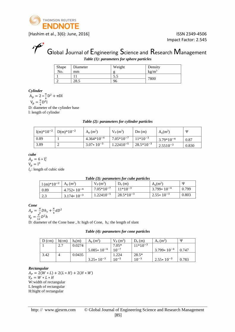
Table (1): parameters for sphere particles
Cylinder
Ap = 2 ∗π
4D2 + πDl
Vp =π
4D2l
D: diameter of the cylinder base
l: length of cylinder
Table (2): parameters for cylinder particles
cube
𝐴𝑝 = 6 ∗ lc2
Vp = l3
𝑙𝑐: length of cubic side
Table (3): parameters for cube particles
l (m)*10−2 Ap (m2) VP (m3) Dn (m) As(m2) Ψ
0.89 4.752∗ 10−4 7.05*10−7 11*10−3 3.799∗ 10−4 0.799
2.3 3.174∗ 10−3 1.22410−5 28.5*10−3 2.55∗ 10−3 0.803
Cone
𝐴𝑝 = 𝜋
2𝐷ℎ𝑠 +
𝜋
4𝑑𝐷2
𝑉𝑝 =𝜋
12𝐷2ℎ
D: diameter of the Cone base , h: high of Cone, hs: the length of slant
Table (4): parameters for cone particles
Rectangular
𝐴𝑃 = 2(𝑊 ∗ 𝐿) + 2(𝐿 ∗ 𝐻) + 2(𝐻 ∗ 𝑊)
𝑉𝑃 = 𝑊 ∗ 𝐿 ∗ 𝐻
W:width of rectangular
L:length of rectangular
H:hight of rectangular
Shape
No.
Diameter
mm
Weight
g
Density
kg/m3 1 11 5.5
7800 2 28.5 96
l(m)*10−2 D(m)*10−2 Ap (m2) VP (m3) Dn (m) As(m2) Ψ
0.89 1 4.364*10−4 7.05*10−7 11*10−3 3.79*10−4 0.87
3.89 2 3.07∗ 10−3 1.22410−5 28.5*10−3 2.5510−3 0.830
D (cm) h(cm) hs(m) Ap (m2) VP (m3) Dn (m) As (m2) Ψ
1 2.7 0.0274
5.085∗ 10−4
7.05*
10−7
11*10−3
3.799∗ 10−4 0.747
3.42 4 0.0435
3.25∗ 10−3
1.224
10−5
28.5*
10−3 2.55∗ 10−3 0.783

[Hashim et al., 3(6): June, 2016] ISSN 2349-4506 Impact Factor: 2.545
Global Journal of Engineering Science and Research Management
http: // www.gjesrm.com © Global Journal of Engineering Science and Research Management
[86]
Table (5):parameters for Rectangular particles
W∗10−2 m
L∗ 10−2
m
H∗ 10−2
m
𝐴𝑃
(𝑚2)
𝑉𝑃
(𝑚3)
𝐷𝑛
(m)
𝐴𝑆
(𝑚2)
Ψ
2 0.7 0.5 5.510−4 7.05*10−7 11*10−3 3.79910−4 0.69
2 3.06 2 3.2410−3 1.22410−5 28.5*10−3 2.5510−3 0.785
USE ANSYS FLUENT 15.0 FOR SIMULATION MATHEMATICAL MODELING Commercial package of FLUENT 15.0 under ANSYS 15.0 software, after graphing the geometry by AUTOCAD
2014 and describe the mesh model by using ANSYS meshing 15.0. The system geometry used in the CFD model
has the dimensions:
Fluid zone cylinder (93,75,55,35) mm inside diameter,(100,80,60,40)mm outer diameter and 1000 mm of
high .
Particle zone: different conflagration in different dimension used to calculate mathematical result for this
simulation .Each particle draw in the four tubes and then import to CFD to evaluate simulation.
Consider a particle with nominal diameter (Dn)located at the axis of a cylindrical tube having a diameter (D)falls
at steady velocity (vo)take from the privous section (Vt)terminal velocity, Prashant, J. J. Derksen(2010), for
particle with incompressible fluid this situation is equal to the fluid moving with cylinder wall at a uniform
velocity (V0=Vt) as shown in figure (2).
Figure (2) falling particle in tube with boundary conditions
Conservation equations of momentum and continuity for turbulent model of the flow are presented in FLUENT
built – in solver.
The Mass Conservation (Continuity) Equation: 𝜕𝜌
𝜕𝑡+ ∇. (𝜌 �⃗�) = 0 (13)
𝑊ℎ𝑒𝑟𝑒; ν⃗⃗: is the velocity vector:
∇. ν⃗⃗ = 0 (14)
Momentum Conservation Equations: 𝜕𝜌
𝜕𝑡+ (𝜌�⃗�) + ∇. (𝜌�⃗��⃗�) = −∇𝑝 + ∇. (𝜏̿) + 𝜌�⃗� + �⃗� (15)
𝜏̿ = 𝜇 [(∇�⃗� + ∇�⃗�𝑇 −2
3∇. �⃗�𝐼] (16)
For an axisymmetric, steady flow the boundary conditions are:
[Hashim et al., 3(6): June, 2016] ISSN 2349-4506 Impact Factor: 2.545
Global Journal of Engineering Science and Research Management
http: // www.gjesrm.com © Global Journal of Engineering Science and Research Management
[87]
1) Inlet Vr=0 ,Vz=V0
2) Outlet p=0 ,𝑑𝑣
𝑑𝑧= 0
3) Symmetry Vr=0
4) Sphere wall Vr=Vz=0
5) Tube wall Vr=0,Vz=V0
At this above governing equation along with the boundary condition are numerically solved this is useful to
introduce some parameters such as drag force also the velocity value is adjusted in such away for all measure of
tubes and study the effect of the wall on the drag force.
Wall correction factor in this study calculation from the ratio for drag force in bounded media to drag force in
unbounded media:
𝐹𝑊 =𝐹𝐷
𝐹𝐷∞
RESULT AND DISCUSSION Behavior of settling velocity
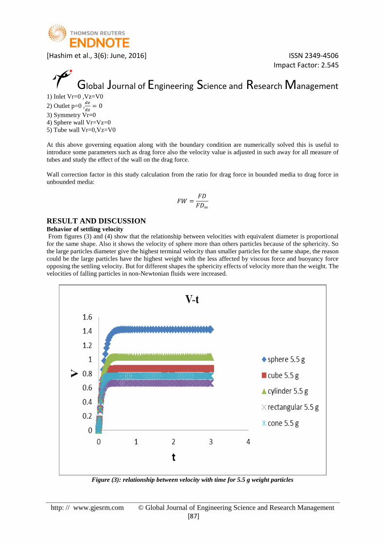
From figures (3) and (4) show that the relationship between velocities with equivalent diameter is proportional
for the same shape. Also it shows the velocity of sphere more than others particles because of the sphericity. So
the large particles diameter give the highest terminal velocity than smaller particles for the same shape, the reason
could be the large particles have the highest weight with the less affected by viscous force and buoyancy force
opposing the settling velocity. But for different shapes the sphericity effects of velocity more than the weight. The
velocities of falling particles in non-Newtonian fluids were increased.
Figure (3): relationship between velocity with time for 5.5 g weight particles

[Hashim et al., 3(6): June, 2016] ISSN 2349-4506 Impact Factor: 2.545
Global Journal of Engineering Science and Research Management
http: // www.gjesrm.com © Global Journal of Engineering Science and Research Management
[88]
Figure (4): relationship between velocity with time for 96 g weight particles
Behavior of wall effect:
From figures (5) up to (9) show the wall correction factor increase with increasing diameter ratio the wall
correction factor calculated from the ratio for drag force in bounded media shown in table (6)&(7) to the drag
force in unbounded media evaluated from extrapolating to data for drag force in bounded media to(d/D=0) , the
drag force increase with increasing diameter ratio because the gap between wall container and particle surface
decrease this lead to relative velocity around particle decrease so the drag force increase.
Table (6): numerical results from ANSYS FLUENT for sphere and cylinder particles
sphere cylinder
Sample1 Sample2 Sample1 Sample2
FD d/D FD d/D FD d/D FD d/D
0.028 0.118 0.496 0.306 0.039 0.118 0.36 0.306
0.029 0.146 0.634 0.38 0.04 0.146 0.39 0.38
0.03 0.2 0.849 0.518 0.041 0.2 0.48 0.518
0.034 0.314 4.762 0.814 0.047 0.314 1.01 0.814
0.0258 0 0.110 0 0.037 0 0.31 0
Table (7): numerical results from ANSYS FLUENT for cube, cone and rectangular particles
cube cone rectangular
Sample1 Sample2 Sample1 Sample2 Sample1 Sample2
FD d/D FD d/D FD d/D FD d/D FD d/D FD d/D
0.028 0.118 0.66 0.306 0.0074 0.118 0.40 0.306 0.0080 0.118 0.45 0.306
0.028 0.146 0.79 0.38 0.0074 0.146 0.46 0.38 0.0087 0.146 0.49 0.38
0.034 0.2 1.07 0.518 0.0077 0.2 0.76 0.518 0.0080 0.2 0.62 0.518
0.030 0.314 4.46 0.814 0.0097 0.314 8.03 0.814 0.0086 0.314 1.61 0.814
0.028 0 0.52 0 0.007 0 0.4 0 0.008 0 0.399 0

[Hashim et al., 3(6): June, 2016] ISSN 2349-4506 Impact Factor: 2.545
Global Journal of Engineering Science and Research Management
http: // www.gjesrm.com © Global Journal of Engineering Science and Research Management
[89]
Figure (5): Relationship of (FW-d/D) for falling sphere in CMC
Figure (6): Relationship of (FW-d/D) for falling cylinder in CMC
Figure (7): Relationship of (FW-d/D) for falling cone in CMC
[Hashim et al., 3(6): June, 2016] ISSN 2349-4506 Impact Factor: 2.545
Global Journal of Engineering Science and Research Management
http: // www.gjesrm.com © Global Journal of Engineering Science and Research Management
[90]
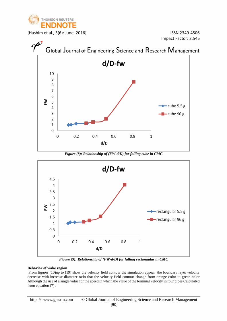
Figure (8): Relationship of (FW-d/D) for falling cube in CMC
Figure (9): Relationship of (FW-d/D) for falling rectangular in CMC
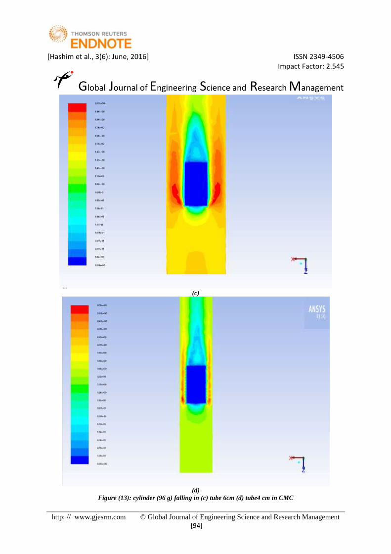
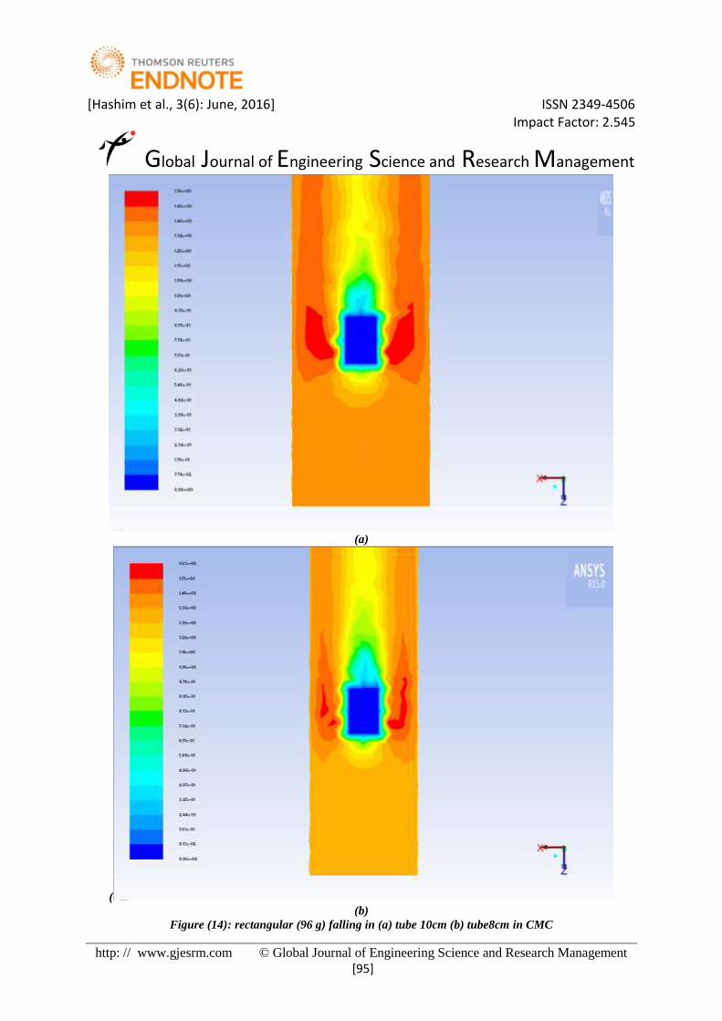
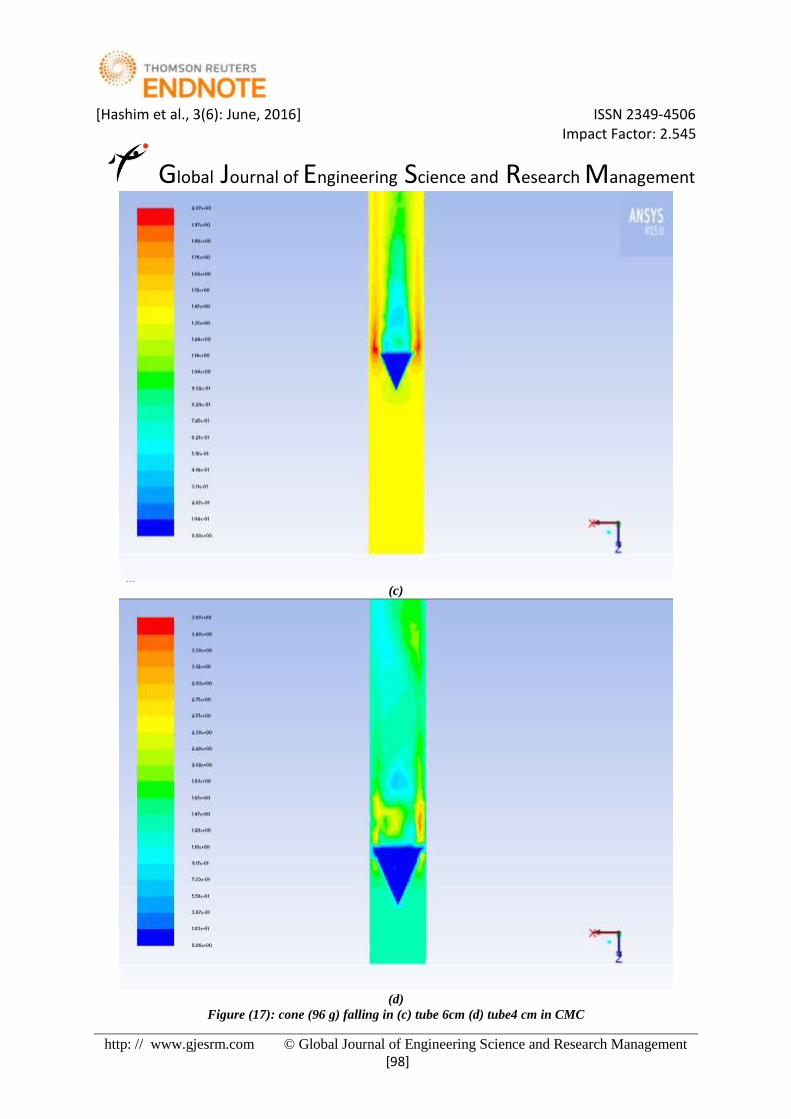
Behavior of wake region
From figures (10)up to (19) show the velocity field contour the simulation appear the boundary layer velocity
decrease with increase diameter ratio that the velocity field contour change from orange color to green color
Although the use of a single value for the speed in which the value of the terminal velocity in four pipes Calculated
from equation (7) .

[Hashim et al., 3(6): June, 2016] ISSN 2349-4506 Impact Factor: 2.545
Global Journal of Engineering Science and Research Management
http: // www.gjesrm.com © Global Journal of Engineering Science and Research Management
[91]
(a)
(b)
Figure (10): sphere (96 g) falling in (a) tube 10cm (b) tube8 cm in CMC

[Hashim et al., 3(6): June, 2016] ISSN 2349-4506 Impact Factor: 2.545
Global Journal of Engineering Science and Research Management
http: // www.gjesrm.com © Global Journal of Engineering Science and Research Management
[92]
(c)
(d)
Figure (11): sphere (96 g) falling in (c) tube 6cm (d) tube4 cm in CMC

[Hashim et al., 3(6): June, 2016] ISSN 2349-4506 Impact Factor: 2.545
Global Journal of Engineering Science and Research Management
http: // www.gjesrm.com © Global Journal of Engineering Science and Research Management
[93]
(a)
(b)
Figure (12): cylinder (96 g) falling in (a) tube 10cm (b) tube8 cm in CMC
[Hashim et al., 3(6): June, 2016] ISSN 2349-4506 Impact Factor: 2.545
Global Journal of Engineering Science and Research Management
http: // www.gjesrm.com © Global Journal of Engineering Science and Research Management
[94]
(c)
(d)
Figure (13): cylinder (96 g) falling in (c) tube 6cm (d) tube4 cm in CMC
[Hashim et al., 3(6): June, 2016] ISSN 2349-4506 Impact Factor: 2.545
Global Journal of Engineering Science and Research Management
http: // www.gjesrm.com © Global Journal of Engineering Science and Research Management
[95]
(a)
(
(b)
Figure (14): rectangular (96 g) falling in (a) tube 10cm (b) tube8cm in CMC

[Hashim et al., 3(6): June, 2016] ISSN 2349-4506 Impact Factor: 2.545
Global Journal of Engineering Science and Research Management
http: // www.gjesrm.com © Global Journal of Engineering Science and Research Management
[96]
(c)
(d)
Figure (15): rectangular (96 g) falling in (c) tube 6cm (d) tube4 cm in CMC

[Hashim et al., 3(6): June, 2016] ISSN 2349-4506 Impact Factor: 2.545
Global Journal of Engineering Science and Research Management
http: // www.gjesrm.com © Global Journal of Engineering Science and Research Management
[97]
(a)
(b)
Figure (16): cone (96 g) falling in (a) tube 10cm (b) tube8 cm in CMC
[Hashim et al., 3(6): June, 2016] ISSN 2349-4506 Impact Factor: 2.545
Global Journal of Engineering Science and Research Management
http: // www.gjesrm.com © Global Journal of Engineering Science and Research Management
[98]
(c)
(d)
Figure (17): cone (96 g) falling in (c) tube 6cm (d) tube4 cm in CMC

[Hashim et al., 3(6): June, 2016] ISSN 2349-4506 Impact Factor: 2.545
Global Journal of Engineering Science and Research Management
http: // www.gjesrm.com © Global Journal of Engineering Science and Research Management
[99]
(a)
(b)
Figure (18): cube (96 g) falling in (a) tube 10cm (b) tube8 cm in CMC

[Hashim et al., 3(6): June, 2016] ISSN 2349-4506 Impact Factor: 2.545
Global Journal of Engineering Science and Research Management
http: // www.gjesrm.com © Global Journal of Engineering Science and Research Management
[100]
(c)
(d)
Figure (19): cube (96 g) falling in (c) tube 6cm (d) tube4 cm in CMC

[Hashim et al., 3(6): June, 2016] ISSN 2349-4506 Impact Factor: 2.545
Global Journal of Engineering Science and Research Management
http: // www.gjesrm.com © Global Journal of Engineering Science and Research Management
[101]
CONCLUSION 1. The wall correction factor effect increase with increasing diameter ratio.
2. Terminal velocity for particle depend on diameter for particle ,sphericity.
3. The value for drag force increase with increasing diameter ratio.
4. The velocity field contour change from orange color to green color ,this mean the velocity decrease with
increasing diameter ratio.
LIST OF SYMBOLS CD : drag coefficient in bounded medium.
D : diameter for tube (m).
d/D: diameter ratio for particle diameter to tube diameter.
Fw : wall correction factor.
FD: drag force in bounded medium .
𝐹𝐷∞:drag force in an unbounded medium.
U:velocity for particle(m/s).
Dn: nominal diameter for particle(m).
Ø:sphericity for particle.
m:mass for particle (Kg).
n:flow behavior index.
𝐹𝐵𝐸:Basset history force (N).
𝐶𝐴: Integrated added mass coefficient.
𝑣:volume for particle (𝑚3).
Re : Reynolds number .
g : Gravitational acceleration, m/s².
K:consistency index (𝑝𝑎. 𝑠𝑛).
GREEK LETTERS ρ:density of fluid (kg/𝑚3).
ϻ:viscosity (pa s).
𝜌𝑝 : Density of particle,(𝐾𝑔/𝑚3).
REFERENCE 1. Bougas and M. Stamatoudis, “Wall factor for acceleration and terminal velocity of falling spheres at high
reynolds numbers,”The ScientificWorld Journal 9Chemical Engineering and Technology, vol. 16, no. 5,
pp. 314–317,1993.
2. A. Unnikrishnan and R. P. Chhabra, “An Experimental study of motion of cylinders in Newtonian fluids:
wall effects and drag coefficient,”The Canadian Journal of Chemical Engineering, vol.69, no. 3, pp. 729–
735, 1991.
3. A. Unnikrishnan and R. P. Chhabra, “Slow parallel motion of cylinders in non-Newtonian media: wall
effects and drag coefficient,” Chemical Engineering and Processing, vol. 28, no. 2,pp. 121–125, 1990.
4. Abbas H. Sulaymon.etal,(2011) Hydrodynamic Interaction Between Two Spheres in Newtonian and non-
Newtonian Fluid, Journal of Applied Sciences Research, 7(7): 1222-1232.
5. Ali Amiri(2013). “wall effect a case study on terminal falling velocity of spherical particles moving in
carreau model fluid.
6. Allen Everett Kaiser(2002),wall effects in hard-sphere suspensions in Newtonian fluids , Texas Tech
University.
7. Arsenijevic.Z.Lj(2010). “wall effect on the velocities of a single sphere settling in a stagnant and counter
current fluid” Powder Technology 203 (2010) 237–242.
8. Ataide .C.H.etal(1999). “wall effect on the terminal velocity of spherical particles in Newtonian and non-
Newtonian fluids”.
9. Beris, A. N., Tsamopoulos, J. A., Armstrong, R. C., & Brown, R. A. (1985). Creeping motion of a sphere
through a Bingham plastic. J. Fluid Mech., 158, 219.

[Hashim et al., 3(6): June, 2016] ISSN 2349-4506 Impact Factor: 2.545
Global Journal of Engineering Science and Research Management
http: // www.gjesrm.com © Global Journal of Engineering Science and Research Management
[102]
10. Blackery, J., & Mitsoulis, E. (1997). Creeping motion of a sphere in tubes filled with a Bingham plastic
material. J. Non-Newtonian Fluid Mech., 70, 59.
11. Brenner (1961)sited in G. Ahmadi Clarkson university ME437/537.
12. Chhabra, R. P. 1993, " bubbles , drops and particles in non- Newtonian fluids " , crc press , boca raton.
13. Chhabra, R. P. and Madhav , V. (1994) “drag on non-spherical particles in non-Newtonian fluid powder
technol”.78 ,77.
14. Chhabra.R.P.(1977). “Wall effect for sphere motion in inelastic non-Newtonian fluids”.
15. Chhabra.R.P.(1995). “wall effect on free settling velocity of non-spherical particles in viscous media in
cylindrical tubes”
16. Chhabra.R.P.(1995). “Wall effect on terminal velocity of non-spherical particles in non-Newtonian
polymer solutions”.
17. Clift, G. J. et al (1978). “bubbles, drops and particles”,. New york: academic press .
18. D.D.Atapattu, R. P. Chhabra, and P.H. T.Uhlherr, “Wall effect for spheres falling at small Reynolds
number in a viscoplastic medium,” Journal of non-Newtonian Fluid Mechanics, vol. 38,no. 1, pp. 31–42,
1990
19. Daoyn Song .etal (2011) “wall effect on a spherical particle settling along the axis of cylindrical tubes
filled with carreau model fluids.comsol conference in Boston.
20. Dhole, S. D., chhabra, r. P. And eswaran ,v. , 2006 , " flow of power-law fluids past a sphere at
intermediate Reynolds numbers " , ind. Eng. Chem. Res., 45(13) ,pp.4773 -4781.
21. Ganser, g. H. (1993). A rational approach to drag prediction of spherical and non-spherical particles.
Powder technology.
22. Hassan.A.F.etal(1996) . “drag on non-spherical particles in non-Newtonian fluids” .
23. Hessameddin .Y(2012). “Analytical solution for settling of non- spherical particles in incompressible
Newtonian media”.
24. Hessameddin Yaghoobi.etal(2012) Analytical solution for settling of non-spherical particles in
incompressible Newtonian media , Powder Technology.
25. Kelessidis, V. C. (2003) (2003). "terminal velocity of solid spheres falling in Newtonian and non-
Newtonian liquids", tech. Chron. Sci. J. Tcg.
26. Kelessidis, V. C. (2004). Measurements and prediction of terminal velocity of solid spheres falling
through stagnant pseudoplastic liquids", j. Of powder technology .
27. King, T. (2006). Forces of newton's law of motion. Cutnel jornal.
28. Li Zhanga.etal (2010), Numerical simulation of a bubble rising in shear-thinning fluids, J. non-
Newtonian Fluid Mech. 165 (2010) 555–567.
29. Luila Abib (2014). “experimental determination of particle sedimentation velocity in opaque drilling
fluids”.
30. Mingzhong Li.etal(2014). “prediction of the wall factor or arbitrary particle settling through various fluid
media in a cylindrical tube using artificial intelligence” Hindawi Publishing Corporatione Scientific
World JournalVolume 2014, Article ID 438782, 10 pages.
31. Missirlis.K.A.(2000). “wall effect for motion of spheres in power law fluids” non-Newtonian Fluid
Mech. 96 (2000) 459–471.
32. Mahmood, H. Y. (2012). Experimental evaluation of the virtual mass and roughness of solid particles
accelerating in Newtonian and non-Newtonian fluids. Baghdad: university of Baghdad.
33. Morrison, A. F. (2013). Data correlation for drag coefficient for sphere. Michigan technological
university, houghton.
34. Muhannad, A .R . (2013). “the effect of particles shape and size and the rheological properties of non-
Newtonian fluids on drag coefficient and particle Reynold’s number relationship. Baghdad: Baghdad
university.
35. P.Y. Huang.etal (1995),Wall effects on the flow of viscoelastic fluids around a circular cylinder non-
Newtonian Fluid Mech., 60 (1995) 179 198.
36. Phillip.P.B(2003). “Sphere drag and settling velocity revisited”.
37. Prashant, J. J. Derksen(2010). “Direct simulations of spherical particle motion in Bingham liquids”.
38. Prashant, J. J.,(2010), Derksen “Direct simulations of spherical particle motion in Bingham liquids”.
Chemical & Materials Engineering Department, University of Alberta, Edmonton.

[Hashim et al., 3(6): June, 2016] ISSN 2349-4506 Impact Factor: 2.545
Global Journal of Engineering Science and Research Management
http: // www.gjesrm.com © Global Journal of Engineering Science and Research Management
[103]
39. R. P. Chhabra and P. H. T. Uhlherr, “Wall effect for high Reynolds number motion of spheres in shear
thinning fluids,”Chemical Engineering Communications, vol. 5, no. 1–4, pp. 115–124, 1980.
40. R. P. Chhabra, “Wall effects on free-settling velocity of non-spherical particles in viscous media in
cylindrical tubes,” Powder Technology, vol. 85, no. 1, pp. 83–90, 1995.
41. R. P. Chhabra, “Wall effects on terminal velocity of non-spherical particles in non-Newtonian polymer
solutions,” Powder Technology, vol. 88, no. 1, pp. 39–44, 1996.
42. Raymond Lau(2013). “revisit of the wall effect on the settling of cylindrical particles in the inertial
regime”.
43. Ron Darbay (2001). “chemical engineering fluid mechanics”.
44. S.F. Chien, Settling velocity of spherical and irregularly shaped particles, SPE Drilling and Completion
9 (1994) 281–289.
45. Sabine Tran-Cong.etal(2004),Drag coefficients of irregularly shaped particles, Powder Technology 139
(2004) 21– 32.
46. Schlichting. (1955). Boundary layer theory. New york.: mcgraw-hill.
47. Shah, N. S. et al (2007). “new model for single spherical particle settling velocity in power law (visco-
inelastic) fluids,. International journal of multiphase flow.
48. Shivam Shahi (2014), “An Experimental Investigation of Settling Velocity of Spherical and Industrial
Sand Particles in Newtonian and non Newtonian Fluids using Particle Image Shadowgraph”. Department
of Civil and Environmental Engineering, Faculty of Engineering University of Alberta
49. Stokes, S. G. (1851). “on the steady motion of incompressible fluids,” ,. Cambridge philosophical society
transactions.
50. Subramaniam, G. , zuritz, c.a. And ultman, j.s. (1991)'' a drag correlation for single spheres in
pseudoplastic tube flow" american society of agricultural engineers
51. Turton, R. and Levenspiel,. O (1986). “a short note on the drag correlation for spheres". Powder
technology.
52. V. Fidleris and R. L.Whitmore, “Experimental determination of the wall effect for spheres falling axially
in cylindrical vessels,”British Journal of Applied Physics, vol. 12, no. 9, article 311, pp.490–494, 1961.
53. Wadell, H. (1933). Sphericity and roundness of rock particles. J. Geol.
54. Yu, Z., & Wachs, A. (2007). A fictitious domain method for dynamic simulation of particle
sedimentation in Bingham fluids. J. non-Newtonian Fluid Mech., 145, 78.
55. ZhangLi.etal(2010). “numerical simulation of a bubble rising in shear thinning fluids”.