Embed Size (px)
Citation preview
MSC.Software 2013 Users Conference
Paper No. AM-CONF13-34
1
A DLM-BASED MSC Nastran AERODYNAMIC FLUTTER
SIMULATOR FOR AIRCRAFT LIFTING SURFACES
Emil Suciu1, Nicholas Stathopoulos
2, Martin Dickinson
3 and John Glaser
4
1Formerly with Bombardier Aerospace; Currently Loads and Dynamics Analyst with
L-3 Communications, 7500 Maehr Drive, Waco, Texas 76715, USA 2Manager, Loads & Dynamics, Bombardier Aerospace
400 Cote-Vertu Road West
Dorval, Quebec, H4S 1Y9, Canada 3Principal Engineering Specialist, Loads & Dynamics, Bombardier Aerospace
4Bombardier Aerospace (Retired)
Summary: A DLM-based aerodynamic simulator for flutter is used to identify some of the
most important aerodynamic drivers for the T-Tail flutter mechanism of a complete aircraft.
The simulator is using the Modal Descrambling Factoring Method, which permits individual
variations of each direct and each interference aerodynamic force, moment and hinge
moment independently of any other force or moment. The sensitivity of the flutter solution
to individual variations of very large numbers of direct and interference aerodynamic
derivatives can be studied with ease.
Keywords: Flutter Simulator, T-Tail, DLM, Modal Descrambling
LIST OF SYMBOLS
lmlmlmlm aaaa 4321 ,,, = lift correction factors for the modal descrambling factoring method for
direct and interference forces and moments, nml ,1,
c = reference chord; also denotes streamwise camber deformation; apparent from the context
ChEh = elevator hinge moment due to horizontal stabilizer h (roll/bending)
ChE = elevator hinge moment due to horizontal stabilizer α (torsion)
ChE(h+) = elevator hinge moment due to horizontal stabilizer h (roll/bending) AND α
(torsion)
ChEβ = elevator hinge moment due to vertical fin yaw β (torsion)
ChEδE = elevator hinge moment due to elevator rotation
ChEδR = elevator hinge moment due to rudder rotation
ChRβ = rudder hinge moment due to yaw (β or V. Fin torsion)
MSC.Software 2013 Users Conference
Paper No. AM-CONF13-34
2
ChRδR = rudder hinge moment due to rudder rotation
CLhVF = horizontal stabilizer lift coefficient due to vertical fin lateral bending h
ClhVF = horizontal stabilizer section lift coefficient due to vertical fin lateral bending h
CL = horizontal stabilizer lift coefficient due to
Cl = horizontal stabilizer section lift coefficient due to
CLβ = horizontal stabilizer lift coefficient due to yaw (β or V. Fin torsion)
Clβ = horizontal stabilizer section lift coefficient due to yaw (β or V. Fin torsion); also
known as the top rolling moment
ClδR = horizontal stabilizer section lift due to rudder rotation (top rolling moment due to R)
Cn = normal force coefficient
CYVFβ = vertical fin side force coefficient due to yaw (β or V. Fin torsion)
DLM = Doublet Lattice Method
HS = Horizontal Stabilizer
h = heave displacement
i,j = indices
k = *c/(2*V), reduced frequency
l,m = indices
Lh, L, Lβ, L = lift due to h, , β and motions (classical notation)
L’ = factored lift
M = Mach Number
Mh, M, M, M = moment about reference axis due to h, , and motions (classical
notation)
n = number of lifting surfaces or components
NBOX = the total number of aerodynamic boxes on the aircraft
Th, T, T, T = control surface hinge moment due to h, , and motions (classical
notation)
q = (1/2)ρV2
= dynamic pressure
QHHL = List of matrices of generalized aerodynamic forces, modal set
Qh, Q, Q, Q = tab hinge moment due to h, , and motions (classical notation)
V = airspeed
Vf = flutter speed
wh, w, w, w, wc = downwash vectors due to h, , , and camber motions
(classical notation)
= pitch (or torsion) angle
= control surface rotation angle; also angle of sideslip or vertical fin torsion; will be
apparent from the context
= tab rotation angle (classical notation)
E = elevator rotation angle
R = rudder rotation angle
Cp = pressure coefficient
ρ = air density
= circular frequency of oscillation
MSC.Software 2013 Users Conference
Paper No. AM-CONF13-34
3
1 INTRODUCTION
The current paper is a revision of the material contained in Reference [1]. The discussion
here applies to all T-Tails analyzed with linear unsteady aerodynamic methods such as the
Doublet Lattice Method (DLM, Reference [2]) with factoring.
Aerodynamic factoring is important; in Reference [3] it is shown that a flutter analysis of an
airplane under development without using factoring for the aileron and tab aerodynamic
hinge moments, when either 2-D strip theory or DLM aerodynamics is used, may not
predict flutter and in this particular case has led to an in-flight flutter incident. Intersecting
(therefore interfering) lifting surfaces pose additional problems for the flutter analyst. FAA
Advisory Circular AC No. 25.629.1A recommends that interference effects be included in
flutter analyses. Parametric variations of calculated aerodynamic forces and moments are
recommended in order to cover uncertainties in calculated values. These parametric
variations are achieved through factoring.
It is known that the T-Tail flutter mechanism (generally referred to as the vertical fin
bending/ torsion mechanism) is strongly influenced by the unsteady aerodynamic forces and
moments present on the horizontal stabilizer. See Reference [4], where the effect of steady
upload on horizontal stabilizer on T-Tail flutter speed is appended to the MSC Nastran
flutter solution (Reference [5]) and an early attempt to separate and factor differently the
horizontal stabilizer direct lift due to horizontal stabilizer pitch/torsion from the interference
lift due to vertical fin torsion on the horizontal stabilizer of a T-Tail is described.
It is also known (Reference [6]) that the unsteady aerodynamic forces and moments present
on the horizontal stabilizer of a T-Tail consist of a superposition of direct forces and
moments resulting from the rigid and elastic motions of the horizontal stabilizer and its
control surfaces and tabs and of interference forces resulting from the oscillating vertical fin
and its control surfaces and tabs. The superimposed direct and interference aerodynamic
forces and moments on the horizontal stabilizer are called stacked forces.
Thus, for general motion of a given arrangement of n lifting surfaces residing in the same
interference group, every lifting surface experiences 1 direct set of forces and moments and
n-1 sets of interference forces and moments. For n>2, each lifting surface experiences more
interference forces than direct forces!
Figure 1 shows a general (or scrambled) mode of vibration of a T-tailed airplane at the
aerodynamic surface.

MSC.Software 2013 Users Conference
Paper No. AM-CONF13-34
4
Figure 1. Scrambled Vertical Fin Bending/Torsion/HS Roll/Elevator Rotation/Rudder Rotation Mode at
the Aerodynamic Surface. A Few Direct and Interference Aerodynamic Forces and Moments are Shown
on the Empennage.
For every mode of vibration, rigid or elastic, the Modal Descrambling factoring method
(formerly known as the General Aerodynamic Derivatives Factoring Method, Reference [6])
performs the descrambling of the general modal motion at every aerodynamic strip and
replaces each scrambled mode with 5 simpler and always the same modes: heave (or
bending), pitch (or torsion), control surface rotation, tab rotation and elastic streamwise
camber deformation. Unsteady direct and interference aerodynamic forces and moments
distributions are then calculated for the descrambled modes and they are available for
factoring separately at every aerodynamic strip (Figure 2).
ClhClClhVF
ClβClδR
ChEδE
ChEh
ChE
ChEβ
ChEδR
ChRβ
ChRδR
CYVFβ
CYVFδR
MSC.Software 2013 Users Conference
Paper No. AM-CONF13-34
5
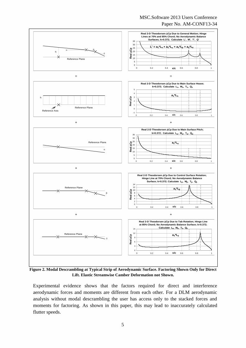
Figure 2. Modal Descrambling at Typical Strip of Aerodynamic Surface. Factoring Shown Only for Direct
Lift. Elastic Streamwise Camber Deformation not Shown.
Experimental evidence shows that the factors required for direct and interference
aerodynamic forces and moments are different from each other. For a DLM aerodynamic
analysis without modal descrambling the user has access only to the stacked forces and
moments for factoring. As shown in this paper, this may lead to inaccurately calculated
flutter speeds.
= =
+ +
+ +
+ +
Real 2-D Theodorsen Cp Due to General Motion; Hinge
Lines at 70% and 85% Chord; No Aerodynamic Balance
Surfaces; k=0.372; Calculate L', M', T', Q'
0
5
10
15
20
25
30
35
0 0.2 0.4 0.6 0.8 1x/c
Rea
l
Cp
L' = a1*Lh + a2*L + a3*L + a4*L
Real 2-D Theodorsen Cp Due to Main Surface Heave;
k=0.372; Calculate Lh, Mh, Th, Qh
-1
0
1
2
3
4
5
0 0.2 0.4 0.6 0.8 1x/c
Real
C
p
a1*Lh
Real 2-D Theodorsen Cp Due to Main Surface Pitch;
k=0.372; Calculate L, M, T, Q
0
5
10
15
20
25
30
35
0 0.2 0.4 0.6 0.8 1x/c
Re
al
C
p a2*L
Real 2-D Theodorsen Cp Due to Control Surface Rotation;
Hinge Line at 70% Chord; No Aerodynamic Balance
Surface; k=0.372; Calculate L, M, T, Q
0
2
4
6
8
10
12
14
0 0.2 0.4 0.6 0.8 1x/c
Re
al
C
p a3*L
Real 2-D Theodorsen Cp Due to Tab Rotation; Hinge Line
at 85% Chord; No Aerodynamic Balance Surface; k=0.372;
Calculate L, M, T, Q
0
3
6
9
12
15
0 0.2 0.4 0.6 0.8 1x/c
Re
al
C
p a4*L
Reference Plane
h
Reference Plane
h
Reference Axis
Reference Plane
Reference Plane
Reference Plane

MSC.Software 2013 Users Conference
Paper No. AM-CONF13-34
6
The MSC Nastran implementation of the DLM (Reference [5]) together with the MSC
Nastran SOL145 with the PKNL flutter solution method chosen and program LSP3G
(Lifting Surface Program 3 General) which implements the Modal Descrambling factoring
method (Reference [6]) and is in effect an aerodynamic flutter simulator are used for
calculating all the results presented here. MSC.PATRAN is used to display and animate
mode shapes.
2 MORE ON THE MODAL DESCRAMBLING FACTORING METHOD
Figure 2 illustrates the summary of the original Modal Descrambling factoring method
showing the descrambling of a general mode of vibration for a lifting surface strip into
simpler motions: heave h, pitch α, control surface rotation β and tab rotation δ and factoring
of the lift. Elastic streamwise camber deformation is not shown in this figure. Elastic
streamwise camber deformation and its effect on flutter calculations are discussed in detail
in Reference [7].
The downwash vectors based on descrambled modal displacements (h, α, β, δ, c) for the
entire aircraft for any elastic or rigid mode look like:
(1)
with the scrambled downwash jw being the sum of the descrambled downwash vectors as
defined for the modal descrambling factoring scheme (Figure 2). The pressure coefficients
and integrated forces and moments can then be obtained for the scrambled or descrambled
modes:
(2)
with i,j=1,NBOX.
If Equation 2 operates on the scrambled modes, we have the typical aerodynamic analysis
which calculates stacked aerodynamic forces and moments and only the stacked forces will
be available for factoring; it will be later seen that this is incorrect. If Equation (2) operates
on the descrambled modes of Equation (1), we have access to the descrambled aerodynamic
forces and moments, but not yet to the interference aerodynamic forces and moments.
In order to calculate the interference aerodynamic forces and moments, the entire aircraft
descrambled downwash vectors are then partitioned into n components. This number is
generally fairly small, such as 4 for the airplane analyzed: (1) wing with associated control
surfaces and tabs, (2) horizontal stabilizer with associated control surfaces and tabs, (3)
vertical fin with associated control surfaces and tabs and (4) engines, pylons, interference
body and ventral fins.
cjjjjhjj wwwwww
jjipi wAC1
MSC.Software 2013 Users Conference
Paper No. AM-CONF13-34
7
The effect of interference is calculated as follows: for any mode, we start with component
(or lifting surface) 1 and we only permit its motion in bending (or h); we then calculate all
direct forces for component 1 due to component 1 bending and the interference forces due to
component 1 bending on the rest of the components, all n-1 of them. Then we only permit
motion in torsion (or α) for component 1 and calculate all direct forces for component 1 due
to component 1 torsion and the interference forces due to component 1 torsion on the rest of
the components; the same sets of direct and interference forces are calculated due to
component 1 moving in the descrambled modes consisting of control surface rotation β,
then tab rotation δ, then elastic streamwise camber deformation c. Once we are done with
component 1, we repeat the process with every component. Reference [6] contains the
mathematical description of this process.
For an aircraft with 4 components, for each mode of vibration descrambled into 5
elementary modes, now we will have to do the processing a total of 20 times vs. one time
for the scrambled mode.
See Figure 2 for an example of the application of correction factors to strip direct lift.
The stacked unfactored lift at any aerodynamic strip of component l is:
(3)
where nml ,1, .
The stacked factored lift at any aerodynamic strip of component l is:
(4)
where as before, nml ,1, and lmlmlmlm aaaa 4321 ,,, are the direct and interference factors on
the lift, respectively. For the time being, the forces and moments due to camber deformation
are not factored, due to a lack of experimental or CFD guidance. Also for the time being,
the real and imaginary forces and moment distributions are factored by the same real factors
derived from steady state wind tunnel and CFD calculations. If unsteady experimental or
CFD guidance is available, the imaginary part can easily be factored differently from the
real part.
Every one of the direct and interference aerodynamic forces and moments for all the lifting
surfaces can be independently factored with pin-point accuracy, including far-fetched
interference effects such as the vertical fin side force due to wing tip aileron tab deflection
or the elevator hinge moment due to wing camber, etc.
Thus, the Modal Descrambling factoring method and simulator program gives the user
unprecedented control over all direct and all interference forces for factoring, on any lifting
surface of the aircraft.
n
m lmlmlmlmlmlmlmlmlm
factoredstacked
l
cLaLaLaLahL
chL
1 4321
,
0.1*)(*)(*)(*)(*)(
)('
n
m lmlmlmlmlm
unfactoredstacked
l cLLLLhLchL1
, )()()()()()(

MSC.Software 2013 Users Conference
Paper No. AM-CONF13-34
8
Experimental data and common sense along with analysis will tell us which interference
effects are important.
Because of linearity, the following is true for the DLM:
(5)
It is also known that for unfactored unsteady DLM analyses,
(6)
However, is the following true for the factored DLM including interference effects?
(7)
where L’ in Equation (7) is given by Equation (4).
Future wind tunnel tests or unsteady CFD calculations will establish the level of
approximation expressed in Equation (7).
3 NUMERICAL RESULTS
Three configurations of a Bombardier stick model of a twin engine airplane with manual
control surfaces are analyzed: Model No. 1 has “nominal” vertical fin bending and torsional
stiffnesses; Model No. 2 has 25% higher vertical fin bending and torsional stiffnesses than
the nominal and Model No. 3 has 50% higher vertical fin bending and torsional stiffnesses
than the nominal configuration. As such, all three models are versions with much reduced
vertical fin stiffnesses of a real airplane model.
Each aileron has a geared tab, the left aileron has a trim tab and the rudder also has a trim
tab. The ailerons, elevators and the rudder all have aerodynamic balance surfaces. Mass
balance is present on all three control surfaces. The control surfaces mechanical circuits are
modeled to include the mass and inertia properties of the control wheels, control columns,
quadrants, cables and pushrods and the elastic properties of the cables and pushrods.
The aerodynamic model of the airplane under consideration is partitioned into four
components as follows: component 1: wing with its ailerons and tabs; component 2:
horizontal stabilizer with its elevators; component 3: vertical fin with its rudder and tab and
the fourth component consists of the pylons, engines and ventral fins. Aerodynamic
correction factors are obtained from steady state wind tunnel data and CFD calculations.
The controls-free configuration is analyzed at one transonic Mach Number. The
aerodynamic model is common for all three structural dynamic models. The effects on
calculated flutter speed of vertical fin bending and torsion stiffness increases and of
variations of aerodynamic derivatives can thus be studied and displayed in a compact format
in parametric fashion.
)()()()()()( cLLLLhLchL DLM
REALITYDLM chLchL )()(
REALITYDLM chLchL )()('
MSC.Software 2013 Users Conference
Paper No. AM-CONF13-34
9
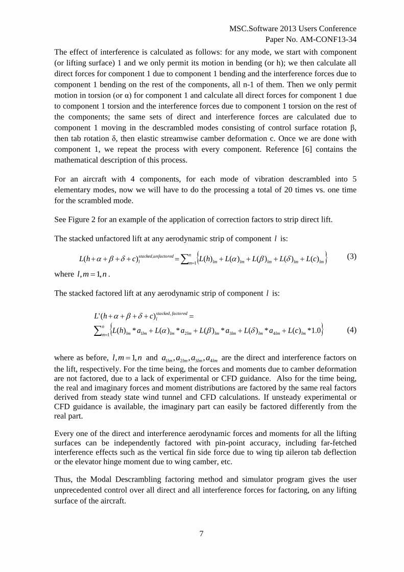
On all the plots of aerodynamic forces the direct forces are plotted in blue and the
interference forces are plotted in red. The same applies to the aerodynamic factors. See
Figures 3 and 4, where all real and imaginary unfactored direct and interference lifts are
plotted on the horizontal stabilizer for a k value of 0.700 at the analysis Mach Number.
Figure 3. Real Parts of Unfactored Descrambled Direct and Interference Cn on Horizontal Stabilizer of the
T-Tail for General Mode of Vibration Shown in Figure 1. k=0.700.
Figure 4. Imaginary Parts of Unfactored Descrambled Direct and Interference Cn on Horizontal Stabilizer
of the T-Tail for General Mode of Vibration Shown in Figure 1; k=0.700.
DESCRAMBLED UNFACTORED DIRECT AND INTERFERENCE REAL Cn ON
HORIZONTAL STABILIZER OF T-TAIL FOR GENERAL (SCRAMBLED) MODE OF
VIBRATION; k=0.700
-0.010
-0.008
-0.006
-0.004
-0.002
0.000
0.002
0.004
0.006
0.008
0 0.1 0.2 0.3 0.4 0.5 0.6 0.7 0.8 0.9 1
semispan η
Rea
l C
n
CN DUE TO HS ROLL/BENDING
CN DUE TO HS TORSION
CN DUE TO ELEVATOR ROTATION
CN DUE TO HS CAMBER
CN DUE TO V. FIN LAT BENDING
CN DUE TO V. FIN TORSION
CN DUE TO RUDDER ROTATION
CN DUE TO RUDDER TAB
ROTATION
CN DUE TO V. FIN CAMBER
DESCRAMBLED UNFACTORED DIRECT AND INTERFERENCE IMAGINARY Cn
ON HORIZONTAL STABILIZER OF T-TAIL FOR GENERAL (SCRAMBLED) MODE
OF VIBRATION; k=0.700
-0.005
0.000
0.005
0.010
0.015
0.020
0.025
0.030
0 0.1 0.2 0.3 0.4 0.5 0.6 0.7 0.8 0.9 1
semispan η
Imag
inary
Cn
CN DUE TO HS ROLL/BENDING
CN DUE TO HS TORSION
CN DUE TO ELEVATOR ROTATION
CN DUE TO HS CAMBER
CN DUE TO V. FIN LAT BENDING
CN DUE TO V. FIN TORSION
CN DUE TO RUDDER ROTATION
CN DUE TO RUDDER TAB
ROTATION
CN DUE TO V. FIN CAMBER

MSC.Software 2013 Users Conference
Paper No. AM-CONF13-34
10
Note the high visibility of the direct lift due to horizontal stabilizer roll/bending and elevator
rotation and of the interference lift due to vertical fin bending and torsion and rudder
rotation. The effect of the vertical fin elastic streamwise camber deformation is visible but
small on the horizontal stabilizer; the rudder trim tab has very high rotational stiffness and at
the low frequency of this mode it rotates negligibly relative to the rudder; the rudder trim
tab has no visible effect at the low frequency of the empennage mode shown in Figure 1.
At each aerodynamic strip of component l , a total of 4 matrices of aerodynamic correction
factors, each 4X4 in size are required, for a total of 64 factors per strip. One 4X4 matrix of
correction factors is the direct set and the other three are the interference sets of matrices of
correction factors for the lift, moment, control surface hinge moment and tab hinge moment.
For 209 strips at one Mach Number, we thus have a total of 13376 (64 factors/strip*209
strips) individual factors to derive and potentially study the effect of each on the flutter
solution.
In Figure 5, a comparison between the Clβ distribution on the horizontal stabilizer as
calculated with the DLM and with a CFD code is shown at the Mach Number analyzed.
Figure 5. Typical DLM vs. CFD Horizontal Stabilizer Spanwise Clβ Distribution. k=0.000.
The factor for the Clβ at every spanwise strip is obtained by dividing the CFD-calculated
value by the DLM-calculated value. At the Mach Number analyzed, the CFD prediction is
larger than the DLM prediction everywhere along the span.
Figure 6 shows a typical variation with Mach Number of the total horizontal stabilizer CLβ
(interference) factor and of the CLα (direct) factor.
DLM vs. CFD Clβ Distribution on Horizontal Stabilizer;
k=0.000
-1.0 -0.8 -0.6 -0.4 -0.2 0.0 0.2 0.4 0.6 0.8 1.0
semispan, η
Cn*
c/c a
ve
CFD
DLMUnit Rigid Yaw Mode

MSC.Software 2013 Users Conference
Paper No. AM-CONF13-34
11
Figure 6. Typical CLα and CLβ Total Factors vs. Mach Number for the Horizontal Stabilizer; k=0.000
At all Mach Numbers, the CLα factor is smaller than unity. At low Mach Numbers, the CLβ
factor is typically greater than unity (and greater than the CLα factor) and it decreases with
increasing Mach Number until it crosses the CLα factor and continues to decrease below the
CLα factor. For the Mach Number analyzed here, the CLβ factor is greater than the CLα
factor.
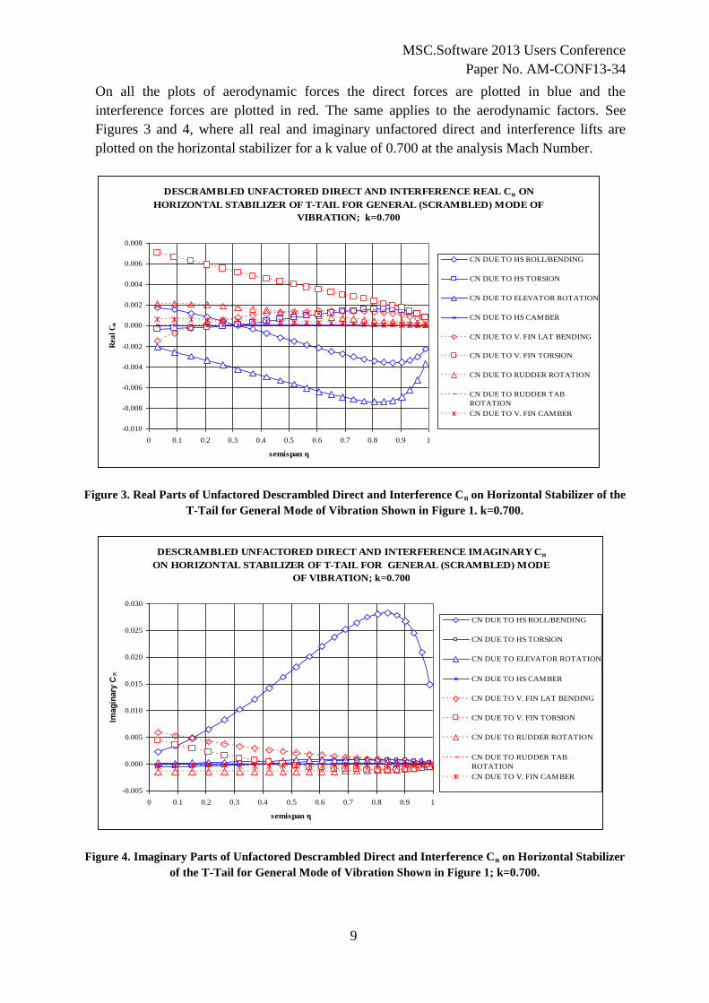
Figures 7 and 8 show the factored and unfactored, real and imaginary, total direct, total
interference and the stacked factored and unfactored real and imaginary lifts on the
horizontal stabilizer at k=0.700. Note the different shapes of the related factored and
unfactored lifts, as well as the relative magnitudes of the real and imaginary parts.
Figure 7. Real Parts of Total Unfactored and Factored Descrambled Direct and Interference Stacked Cn
on Horizontal Stabilizer of the T-Tail for General Mode of Vibration Consisting of Vertical Fin
Bending/Torsion/HS Roll/Elevator Rotation/Rudder Rotation Shown in Figure 1. k=0.700.
Typical Horizontal Stabilizer CLα and CLβ Factors
vs. Mach Number; k=0.000
Mach Number M
Aer
od
yn
am
ic F
act
ors
CLα Factor vs. M
CLβ Factor vs. M
Analysis CLβ Factor
Analysis CLα Factor
1.000
CLα Factor<1.000
CLβ Factor>1.000
CLβ Factor<1.000
TOTAL UNFACTORED AND FACTORED DIRECT, INTERFERENCE AND
STACKED REAL Cn ON HORIZONTAL STABILIZER OF T-TAIL FOR GENERAL
(SCRAMBLED) MODE OF VIBRATION ; k=0.700
-0.010
-0.005
0.000
0.005
0.010
0.015
0.0 0.2 0.4 0.6 0.8 1.0
semispan η
Real
Cn
UNFACTORED TOTAL DIRECT LIFT
FACTORED TOTAL DIRECT LIFT
UNFACTORED INTERFERENCE LIFT
FACTORED INTERFERENCE LIFT
UNFACTORED STACKED
FACTORED STACKED
MSC.Software 2013 Users Conference
Paper No. AM-CONF13-34
12
Figure 8. Imaginary Parts of Total Unfactored and Factored Descrambled Direct and Interference
Stacked Cn on Horizontal Stabilizer of the T-Tail for General Mode of Vibration Shown in Figure 1.
k=0.700.
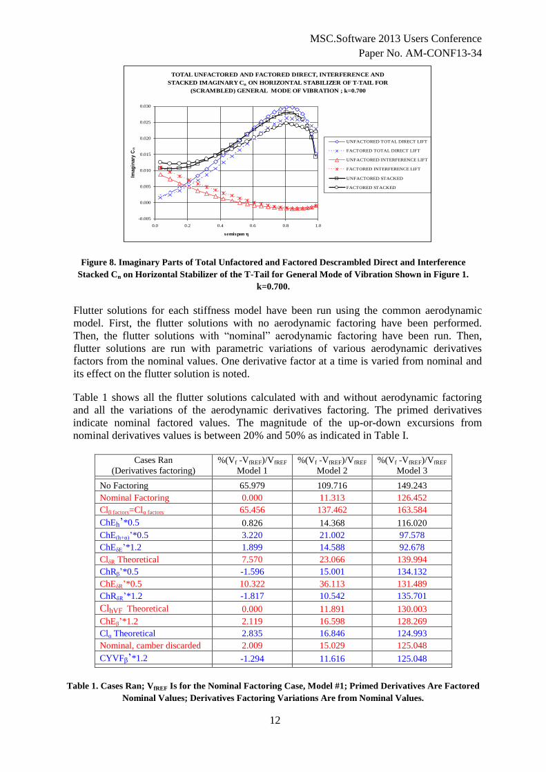
Flutter solutions for each stiffness model have been run using the common aerodynamic
model. First, the flutter solutions with no aerodynamic factoring have been performed.
Then, the flutter solutions with “nominal” aerodynamic factoring have been run. Then,
flutter solutions are run with parametric variations of various aerodynamic derivatives
factors from the nominal values. One derivative factor at a time is varied from nominal and
its effect on the flutter solution is noted.
Table 1 shows all the flutter solutions calculated with and without aerodynamic factoring
and all the variations of the aerodynamic derivatives factoring. The primed derivatives
indicate nominal factored values. The magnitude of the up-or-down excursions from
nominal derivatives values is between 20% and 50% as indicated in Table I.
Cases Ran
(Derivatives factoring)
%(Vf -VfREF)/VfREF
Model 1
%(Vf -VfREF)/VfREF
Model 2
%(Vf -VfREF)/VfREF
Model 3
No Factoring 65.979 109.716 149.243
Nominal Factoring 0.000 11.313 126.452
Clβ factors=Clα factors 65.456 137.462 163.584
ChEh’*0.5 0.826 14.368 116.020
ChE(h+α)’*0.5 3.220 21.002 97.578
ChEδE’*1.2 1.899 14.588 92.678
ClδR Theoretical 7.570 23.066 139.994
ChRβ’*0.5 -1.596 15.001 134.132
ChEδR’*0.5 10.322 36.113 131.489
ChRδR’*1.2 -1.817 10.542 135.701
ClhVF Theoretical 0.000 11.891 130.003
ChEβ’*1.2 2.119 16.598 128.269
Clα Theoretical 2.835 16.846 124.993
Nominal, camber discarded 2.009 15.029 125.048
CYVFβ’*1.2 -1.294 11.616 125.048
Table 1. Cases Ran; VfREF Is for the Nominal Factoring Case, Model #1; Primed Derivatives Are Factored
Nominal Values; Derivatives Factoring Variations Are from Nominal Values.
TOTAL UNFACTORED AND FACTORED DIRECT, INTERFERENCE AND
STACKED IMAGINARY Cn ON HORIZONTAL STABILIZER OF T-TAIL FOR
(SCRAMBLED) GENERAL MODE OF VIBRATION ; k=0.700
-0.005
0.000
0.005
0.010
0.015
0.020
0.025
0.030
0.0 0.2 0.4 0.6 0.8 1.0
semispan η
Imag
inary
Cn
UNFACTORED TOTAL DIRECT LIFT
FACTORED TOTAL DIRECT LIFT
UNFACTORED INTERFERENCE LIFT
FACTORED INTERFERENCE LIFT
UNFACTORED STACKED
FACTORED STACKED

MSC.Software 2013 Users Conference
Paper No. AM-CONF13-34
13
When a derivative is listed such as “ClδR Theoretical” in Table 1, it means that the
unfactored DLM-calculated value is used.
Figure 9 shows in graphical form the effect of both stiffness (and therefore mode shape)
variation and aerodynamic derivatives variation on the flutter mechanism of the T-Tail of all
three models analyzed. For clarity, not all the cases listed in Table 1 are plotted in Figure 9.
Figure 9. Effect of Vertical Fin Stiffness Variations and of Aerodynamic Factoring Variations, One
Derivative at a Time from Nominal on Flutter Speed of T-Tailed Aircraft. Primed Derivatives Are
Factored Nominal Values. Reference Speed Is for Nominal Factoring, Model 1.
It is immediately apparent that the change in the flutter solution due to changes in the Clβ
factors is dramatic; at the Mach Number analyzed, the T-Tail flutter speeds calculated with
the Clβ factors = Clα factors are decidedly optimistic (see Table 1 and Figures 6 and 9).
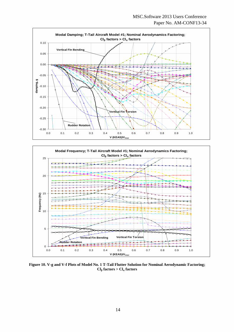
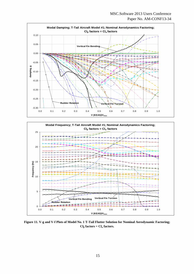
Figures 10 and 11 show the V-g and V-f plots for the complete aircraft for the nominal
factoring case (with the Clβ factors > Clα factors) and then for the nominal factors but with
the Clβ factors being equal to the Clα factors for Model No. 1. Again, the change in the T-
Tail flutter speed due to changes in the Clβ factors is dramatic.
MOST FLUTTER ANALYSES ARE HERE
SOME ARE HERE
ALL SHOULD BE HERE
MSC.Software 2013 Users Conference
Paper No. AM-CONF13-34
14
Figure 10. V-g and V-f Plots of Model No. 1 T-Tail Flutter Solution for Nominal Aerodynamic Factoring;
Clβ factors > Clα factors
Modal Damping; T-Tail Aircraft Model #1; Nominal Aerodynamics Factoring;
Clβ factors > Clα factors
-0.30
-0.25
-0.20
-0.15
-0.10
-0.05
0.00
0.05
0.10
0.0 0.1 0.2 0.3 0.4 0.5 0.6 0.7 0.8 0.9 1.0
V (KEAS)/Vmax
da
mp
ing
, g
Vertical Fin Bending
Vertical Fin Torsion
Rudder Rotation
Modal Frequency; T-Tail Aircraft Model #1; Nominal Aerodynamics Factoring;
Clβ factors > Clα factors
0
5
10
15
20
25
0.0 0.1 0.2 0.3 0.4 0.5 0.6 0.7 0.8 0.9 1.0
V (KEAS)/Vmax
Fre
qu
en
cy
(H
z)
Vertical Fin Bending Vertical Fin Torsion
Rudder Rotation
MSC.Software 2013 Users Conference
Paper No. AM-CONF13-34
15
Figure 11. V-g and V-f Plots of Model No. 1 T-Tail Flutter Solution for Nominal Aerodynamic Factoring;
Clβ factors = Clα factors.
Modal Damping; T-Tail Aircraft Model #1; Nominal Aerodynamics Factoring;
Clβ factors = Clα factors
-0.30
-0.25
-0.20
-0.15
-0.10
-0.05
0.00
0.05
0.10
0.0 0.1 0.2 0.3 0.4 0.5 0.6 0.7 0.8 0.9 1.0
V (KEAS)/Vmax
da
mp
ing
, g
Vertical Fin Bending
Vertical Fin TorsionRudder Rotation
Modal Frequency; T-Tail Aircraft Model #1; Nominal Aerodynamics Factoring;
Clβ factors = Clα factors
0
5
10
15
20
25
0.0 0.1 0.2 0.3 0.4 0.5 0.6 0.7 0.8 0.9 1.0
V (KEAS)/Vmax
Fre
qu
en
cy
(H
z)
Vertical Fin Bending Vertical Fin Torsion
Rudder Rotation
MSC.Software 2013 Users Conference
Paper No. AM-CONF13-34
16
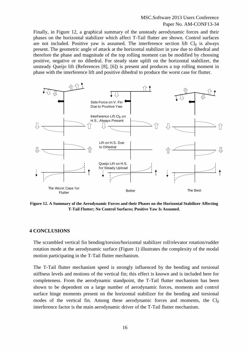
Finally, in Figure 12, a graphical summary of the unsteady aerodynamic forces and their
phases on the horizontal stabilizer which affect T-Tail flutter are shown. Control surfaces
are not included. Positive yaw is assumed. The interference section lift Clβ is always
present. The geometric angle of attack at the horizontal stabilizer in yaw due to dihedral and
therefore the phase and magnitude of the top rolling moment can be modified by choosing
positive, negative or no dihedral. For steady state uplift on the horizontal stabilizer, the
unsteady Queijo lift (References [8], [6]) is present and produces a top rolling moment in
phase with the interference lift and positive dihedral to produce the worst case for flutter.
Figure 12. A Summary of the Aerodynamic Forces and their Phases on the Horizontal Stabilizer Affecting
T-Tail Flutter; No Control Surfaces; Positive Yaw Is Assumed.
4 CONCLUSIONS
The scrambled vertical fin bending/torsion/horizontal stabilizer roll/elevator rotation/rudder
rotation mode at the aerodynamic surface (Figure 1) illustrates the complexity of the modal
motion participating in the T-Tail flutter mechanism.
The T-Tail flutter mechanism speed is strongly influenced by the bending and torsional
stiffness levels and motions of the vertical fin; this effect is known and is included here for
completeness. From the aerodynamic standpoint, the T-Tail flutter mechanism has been
shown to be dependent on a large number of aerodynamic forces, moments and control
surface hinge moments present on the horizontal stabilizer for the bending and torsional
modes of the vertical fin. Among these aerodynamic forces and moments, the Clβ
interference factor is the main aerodynamic driver of the T-Tail flutter mechanism.
Interference Lif t Clβ on
H.S.; Always Present
Lif t on H.S. Due
to Dihedral
Queijo Lif t on H.S.
for Steady Upload
Side Force on V. Fin
Due to Positive Yaw
The Worst Case for
FlutterBetter The Best
MSC.Software 2013 Users Conference
Paper No. AM-CONF13-34
17
The second most important driver is the elevator hinge moment due to elevator rotation,
then it is the elevator hinge moment due to horizontal stabilizer roll/bending and torsion,
broken down into about 1/3rd
due to horizontal stabilizer roll/bending and 2/3rd
due to
pitch/torsion. The factors on the ClδR and ChEδR also have a strong effect on the calculated
speed of the T-Tail flutter mechanism. The flutter speed sensitivity due to variations of the
horizontal stabilizer lift due to vertical fin lateral bending is relatively small (see Table 1).
Vertical fin direct derivatives variations have small but measurable effects on calculated T-
Tail flutter speeds for all three airplane models. The elastic streamwise camber deformation
on the entire aircraft also has a small effect on the T-Tail flutter speeds for all three airplane
models (Table 1); the camber effect is more pronounced on other aircraft lifting surfaces
calculated flutter speeds (see also Reference [7]).
The presence of the wing aerodynamic surface with or without factoring also influences the
T-Tail flutter mechanism. Whether the wing is or is not in the same interference group with
the T-Tail lifting surfaces has little effect on the calculated T-Tail flutter speed; the effect is
mostly dynamic, transmitted through the fuselage.
The effects on the calculated T-Tail flutter mechanism speed of individual variations of all
these aerodynamic forces, moments and hinge moments have been explored (Figure 9)
through the use of the flutter simulator program implementing the Modal Descrambling
factoring method.
A good knowledge of measured or CFD-calculated direct and interference aerodynamic
derivatives is therefore essential for the accurate calculation of the T-Tail flutter mechanism
speed using the DLM or similar methods and the Modal Descrambling Factoring Method.
Other applications of the Flutter Simulator program implementing the Modal Descrambling
Factoring Method are for the flutter analysis of the wing-horizontal stabilizer in close
vertical proximity and for the wing-engine nacelle flutter analysis; aerodynamic interference
is important for these cases. Gust loads analyses could also benefit from the use of the
Modal Descrambling Factoring Method. Last but not least, the more accurate set of
generalized aerodynamic forces matrices QHHL generated by the Modal Descrambling
Factoring method can be used in nonlinear calculations of limit cycle oscillations caused by
control surface free play (Reference [9]).
The flutter simulator program gives the user unprecedented control over all direct and all
interference aerodynamic forces, moments and control surfaces and tabs hinge moments for
factoring on any lifting surface of the aircraft.
5 ACKNOWLEDGEMENTS
Messrs. Frederic Bradley and Jason Bensimhon of the Bombardier Dynamics Group have
contributed with the preparation of the structural dynamic model and with the voluminous
aerodynamic data compilation required for this project.
MSC.Software 2013 Users Conference
Paper No. AM-CONF13-34
18
6 REFERENCES
[1] Suciu, E., Stathopoulos, N., Dickinson, M. and Glaser, J.,”The T-Tail Flutter Mechanism
Revisited”, Paper No. IFASD-2011-121, Presented at the International Forum for
Aeroelasticity and Structural Dynamics, Paris, France, June 26-30, 2011.
[2] Giesing, J.P., Kalman, T.P., and Rodden, W.P., “Subsonic Unsteady Aerodynamics for
General Configurations, Part I, Vol. I – Direct Application of the Nonplanar Doublet
Lattice Method”. Air Force Flight Dynamics Laboratory Report No. AFFDL-TR-71-5
Part I, Vol. I, 1971.
[3] French, R.M., Noll, T.,Cooley, D.E., Moore, R. and Zapata, F.; "Flutter Prediction
Involving Trailing Edge Control Surfaces"; Journal of Aircraft, May 1988, Vol 25, No 6.
[4] Suciu, E., “MSC/NASTRAN Flutter Analyses of T-Tails Including Horizontal Stabilizer
Static Lift Effects and T-Tail Transonic Dip”, Presented at the 1996 MSC/NASTRAN
World Users’ Conference, Newport Beach, CA, June 3-7, 1996.
[5] Rodden, W.P., and Johnson, E.H., “User’s Guide V68, MSC Nastran Aeroelastic
Analysis”, The MacNeal-Schwendler Corporation, Los Angeles, CA, 1994.
[6] Suciu, E., “A General Aerodynamic Derivatives Factoring Method for the MSC Nastran
DLM Capable of Controlling All Lifting Surfaces Aerodynamic Forces and Moments,
Including All Interference Effects”, Paper No. 2003-39, MSC.Software 2003 Virtual
Product Development Conference, October 13 - 15, 2003, Dearborn, Michigan, USA.
[7] Panza, J.L., and Suciu, E., “A Closer Look at the Elastic Streamwise Camber
Deformation of Swept and Unswept Wings”, Presented at the International Forum on
Aeroelasticity and Structural Dynamics 2005 as Paper No. IF-090, Munich, Germany,
June 28 – July 1, 2005.
[8] Queijo, M.J., “Theoretical Span Load Distributions and Rolling Moments for
Sideslipping Wings of Arbitrary Planform in Incompressible Flow”, NACA Report
1269, 1956.
[9] Kholodar, D., and Dickinson, M., “Aileron Freeplay”, International Forum on
Aeroelasticity and Structural Dynamics Paper No. IFASD-2009-158, Seattle, WA, June
21-24, 2009.