Embed Size (px)
Citation preview

0 THE SOUND ENGINEERING MAGAZINE
NOVEMBER 1968 75c
European Equipment and U.S. Audio
An Electronic -Music Synthesizer
Test Tapes
t 10 01 R N 2110. IA 3 N
RAV Hso EVE
O NI BJttbt'VÑOtÿúÑ3-r,tt 1
www.americanradiohistory.com

For technical sound recording everyí ; b points to Revox
Plug-in power amplifiers /optional/.
Separate spooling motors of original high torque, low
weight construction.
Sealed mains input section and cabinet safety link socket. Fully electronically
stabilised power supply circuit.
Capstan motor servo control panel maintaining speed
accuracy to better than
0.2% and incorporating elec-
tronic speed change from
71 to 31 ips.
Read head of cap
stan motor.
Capstan motor of patented construction. cool running, low current consumption and wow and flutter better than international broadcast requirements.
Professional prac
tice glass fibre panel with integral gold -plated switch contacts.
Tape transport logic
control circuit panel.
Plug-in relays control- .- 41 ling all functions and
eliminating damage from inadvertent mis-
,cj handling.
Plug -in 120 Kc /s bias oscillator ob-
viates multiplex interference.
Unique multi -bank micro -switch unit. pro-
viding on -off. speed and
spool size /tension varia- tions on one control.
Plug -in record relay.
New from the Willi Studer Factory comes the revolutionary Model 77 incorporating design developments based on experience gained in the broadcast field with the 37 and 62 Series Studer machines. The 77 is a studio quality machine compactly presented and offering features unique in this price class including total Write or call for loather information - - REVOX CORPORATION, 212, Mineola Avenue, Roslyn Heights, N.Y. 11577. New York. Telephone: (516) 484 -4650.
indifference to fluctuations in mains supply periodicity. With a wow and flutter level below broadcast standard requirements plus a linear response from 20- 20,000 Hz at 71 ips. (*2 db) and an ultra low noise level, this new Revox now sets the standard by which the rest will be
judged.
Plug in audio input/ output amplifiers.
Circle 11 on Reader Service Card
www.americanradiohistory.com

Coming \ext Month
Acousta -Voiced Monitoring Systems part one, by Don Davis of Altec will describe the applications of this special form of acoustic equalization to several auditioning and monitoring rooms of a
recording studio. The purpose is to achieve both flat and identical sound in each of the several auditioning studios. According to the author the result is a
calibrated listening system that pro- vides the engineer with a true audio picture of what is happening in his studio.
Our roving camera poked its lens into most of the exhibitry at the Audio Engineering Society's New York Con- vention. The result will be a compre- hensive picture gallery of exciting new equipment, many items shown for the first time.
And there will be our regulat colum- nists, George Alexandrovich, Norman H. Crowhurst, Martin Dickstein, and John A. McCulloch.
Coming next month in db, The Sound Engineering Magazine.
About the
Covor The artwork represents a linear con-
troller for an electronic music synthe- sizer. It can be constructed and used much the same as a fret board of a
guitar. Robert C. Ehle's article begins on page 22.
THE SOUND ENGINEERING MAGAZINE
NOVEMBER 1968Volume 2, Number 10
I abb of Contents FEATURE ARTICLES
European Equipment and U.S. Audio Stephen F. Temmer 17
An Electronic Music Synthesizer Robert C. Ehle 22
Test Tapes Robert K. Morrison and John G. McKnight 26
MONTHLY DEPARTMENTS Letters 2
The Feedback Loop omitted this John A. McCulloch month
The Audio Engineer's Handbook George Alexandrovich 4
Theory and Practice Norman H. Crowhurst 10
Sound With Images Martin Dickstein 14
Editorial 16
New Products and Services 32
The db Bookcase 34
Classified 35
People, Places, Happenings 36
EDITORIAL BOARD OF REVIEW George Alexandrovich
Sherman Fairchild Norman Anderson
Prof. Latif Jiji Daniel R. von Recklinghausen
William L. Robinson Pau! Weathers
John H. McConnell
db, the Sound Engineering Megeeint Is published monthly by Sagamore Publishing Company, Inc. Entire contents copyright ®1968 by Sagamore Publishing Co., Inc., 980 Old Country Road, Plainview, L.I., N.Y. 11803. Telephone (516) 433.6530. db is distributed to qualified individuals and firms in professional audio -recording, broadcast, audio -visual, sound reinforcement, consultants, video recording, film sound, etc. Application must be made on an official subscription form or on a company letterhead. Subscriptions are $6.00 per year ($7.00 per year outside U. S. Possessions, Canada, and Mexico) in U. S. funds. Single copies are 75c each. Controlled Circulation postage paid at Easton, Pa. 18042. Editorial, Publishing, and Sales Offices: 980 Old Country Road, Plainview New York 11803. Postmaster: Form 3579 should be sent to above address.
www.americanradiohistory.com

oa
One of a series of brief discussions by Electro -Voice engineers
PAGING
PROGRESS
REPORT LARRY SALZWEDEL Loudspeaker Project Engineer
Paging speakers represent one of the more interesting challenges to the electro- acoustic designs because of the many limitations im- posed by function. Both size and cost are re- stricted. In addition, paging speakers must be efficient, easy to install, and unusually reliable. In recent months, Electra -Voice paging units have been redesigned to meet ever-higher stand- ards of performance.
Some of the changes were internal and subtle, Yet most significant in terms of operation. For instance, the thickness of the front plate of the magnetic structure was increased to achieve optimum flux in the gap. The result was reduced leakage, increased total flux, and almost the same flux per unit area, without the need to increase magnet weight.
As a result of this change, bass response was improved down to horn cutoff, over- damping at low frequencies was reduced, and 2 dB higher bass efficiency was achieved.
High- frequency response was also improved, primarily as a result of modifications to the loading lug. Interferences at the throat area
were reduced by providing a large number of small entrances between the cavity in front of the diaphragm and the throat of the horn. This resulted in more uniform response and an in- crease of about 2 dB in high -frequency output, plus somewhat extended high -frequency re- sponse.
Io addition to these internal changes common to both the rectangular PA30A and the PA3OR, the horn shape of the round PA3OR offers several unique advantages. Horn flare has been calculated to offer the proper impedance match while still flaring fast enough at the mouth to permit frequencies above 4kHz. to be spread more uniformly than is typical. About 15 to 18° wider coverage is achieved to improve intelligi- bility over a wider area.
Both speakers are now available with matching transformers built into the base of the mount. These units offer 5 output levels instantly se- lected from an externally accessible switch. Both 25 -volt and 70.7 -volt models are offered. The design changes, while modest in impor- tance individually, add up to a substantial im- provement in overall performance.
For reprints of other discussions in this series, or technical data on any E -V product, write:
ELECTRO- VOICE, INC., Dept. 1183BD 686 Cecil St., Buchanan, Michigan 49107
gLete-- acz A SUBSIDIARY OF GULTON INDUSTRIES. INC.
Circle 15 on Reader Service Card
Lottors
The Editor: One or more of your more informed readers may have called attention to the flux density figures in my article in your September issue (A NEW RIBBON MIRPOPRONE). The actual figure is five thousand Gauss minimum, not three thousand as stated, and it is not the highest obtainable or obtained, since it is possible to get higher figures at the expense of extended frequency response.
David B. Hancock New York, N.Y.
The Editor: Although High Fidelity and Stereo were among the first consumer publica- tions to use hertz to replace cycles -per- second, I can see that one may have mixed feelings about this change.
From the standpoint of consistency with other terms, such as decibels, watts, amperes, volts, ohms, and so on -which all were named after people -the term hertz makes sense.
But it can be questioned, from the standpoint of who did what and when. Perhaps Hertz is not the name to use. Has anyone thought of Helmholtz? Or was this name rejected on aesthetic grounds (can you imagine saying to someone, "This speaker goes down to 25 helmholtz," and having him answer, "Yes but mine goes up to 19,000 hockfleisch. ") ?
Or consider referring to a loudness contour curve as a Fletcher- Munsonism or saying that the preamp was "RIAA- ed fairly accurately," or "I'm going to my doctor to be roentgenized," and so on.
When you get to musical pitch, you might as well justify using backs as hertz in place of cycles -per -second. Old Johann S. tempered the keyboard long before Heinrich tampered with wave propogation.
The real telling point in the anti - hertz argument is that we had a per- fectly good, accurate description of the phenomenon in cycles- per -second. Pre- cise, to the point, and no quibbling about exactly what was meant. We had no such expressions for what has become amperes, volts, etc. and therefore had to improvise. As I said, we in HF and Stereo adopted hertz - our of respect for the prevailing usage - but it wouldn't make us or our readers un- happy if the profession went back to cycles- per -second.
Norman Eisenberg Audio -Video Editor High Fidelity Magazine
Robert Bach PUBLISHER
Larry Zide EDITOR
Bob Laurie ART DIRECTOR
Marilyn Gold COPY EDITOR
Charles N. Wilson ASSISTANT EDITOR
Richard L. Lerner ASSISTANT EDITOR
A. F. Gordon CIRCUL ATION MANAGER
David Pollens ASST. CIRCULATION MGR.
SALES OFFICES
New York 980 Old Country Road Plainview, N.Y. 11803
516- 433 -6530
Denver Roy McDonald Associates, Inc.
846 Lincoln Street Denver, Colorado 80203
303-825-3325
Houston Roy McDonald Associates, Inc.
3130 Southwest Freeway Houston, Texas 77006
713-529-6711
Tulsa Roy McDonald Associates, Inc.
2570 S. Harvard Ave. Tulsa, Oklahoma 74114
918- 742 -9961
Dallas Roy McDonald Associates, Inc.
Semmons Tower West Suite 411
Dallas, Texas 75207 214-637-2444
San Francisco Roy McDonald Associates Inc.
625 Market Street San Francisco, California 94105
415- 397 -5377
Los Angeles Roy McDonald Associates, Inc.
1313 West 8th Street Los Angeles, California 90017
413- 483 -1304
Portland Roy McDonald Associates, Inc.
2035 S.W. 58th Avenue Portland, Oregon 97221
503-292-8521
www.americanradiohistory.com

IF THE CROWN CX822 IS JUST ANOTHER TAPE RECORDER - the Stradivarius is just another violin
= The Crown CX822 has been opening eyes in testing labs all over America. In early 1968 Audio magazine put it to the test, and published its findings in the April Equipment Report. Following are a few excerpts = from that report:
_ "The CX822 is a serviceman's dream, considering the = unit's inherent complexity."
"The Crown CX822 . . . is probably the finest tape = recorder that has been reviewed in these pages. In = addition to delivering phenomenal performance, it incorporates numerous features and refinements that = place this machine in a class by itself."
"Playing back first -generation transfers from original masters, the sound produced through the Crown CX822 was peerless. When recording and playing back from records and FM broadcasts, there was absolutely no aural difference between the original and the copy at 15 ips. The same held true at 71/2 ips, though theory says, there should have been."
"Tape threading is delightfully simple." _ "Editing facilities are great."
Construction appears to be rugged enough to with- _ = stand parachute drops."
"We found the tape motion command system to be as foolproof as Crown says it is, and could not beat the computer by design or by accident :'
The new Crown CX822 is capable of providing the most faithful reproduction of sound through the mag- netic recording medium that we have observed to date. And it does it in as foolproof and as easy a way as we've seen."
5he Stradivarius of the 5ape 'industry
To receive your copy of the 4 -page Audio test report, check the reader service card, or write:
International Box 1000, Dept. 0311 = Elkhart, Indiana 46514
Circle 18 on Reader Service Card w
www.americanradiohistory.com

FASTEST
LIMITER OUT OF THE WEST
ULTRA -FAST attack time
SOLID -STATE stable operation
NO BALANCING ever required
Like a fast "Gun Slinger ", the 1176 Limiting Amplifier has ULTRA -FAST attack time...and it's adjustable - less than 20
µsec. to 800 µsec. You get "quick - draw" action with pushbutton selection of four compression ratios and four meter settings. Re-
lease time is adjustable from the
front panel, independent of the de-
gree of limiting.
The compact 1176 fits a 19" rack
and uses only 31/2" of vertical space. It has self- contained regu-
lated power supplies...so, why not
"draw a bead" on one and see for yourself.
Write for complete technical informa tion today! Some prime Rep, and Distributor Terri. tories still available.
PRODUCTS OF 7MPT 11922 VALERIO STREET
NO. HOLLYWOOD, CALIF. 91605 TEL. (213) 764.1500
v IVTET UNITED RECORDING ELECTRONICS INDUSTRIES
Circle 14 on Reader Service Card
I ko Audio Engineer's I Iancbook
GEORGE ALEXANDROVICH
PATCH BAYS
A patch bay is seldom thought of as a switch, along with its patch cords. But the only difference between a regular switch and a patch bay is that the patch cord represents a flexible wiper while conventional switches may have a sta- tionary type. A patch bay offers a de- gree of flexibility not available in any other type of switch that uses standard proven hardware. Whether you want to insert a piece of equipment into the chain or change the direction of signal flow by patching the signal through different paths - a patch bay is the answer.
Introducing a new element into an audio chain requires that we break the chain and insert the new equipment's inputs and outputs at the proper points. Special contacts in the patch bay ac- complish this. The insertion of the patch cord into the connectors switches the circuit from feed- through to a feed into the patch cord. This, in turn, can be connected to any circuit designed to match the circuit broken by the patch cord.
Patch bays, just as other switch types, are available with contacts that vary from simple form A to sophisti- cated single or double form D systems. Older type of patch cords used double prongs; more recent patch cords for audio applications use a single prong consisting of a tip -ring and sleeve con- tact surface. The advantage of this tip - ring- sleeve patch cord is that polarity and phasing is maintained constant - so important to multi -channel installa- tions.
Although much of the engineering fraternity still likes patching facilities, more and more consoles are being made without patch bays. This may, in part, be explained by the fact that the audio industry accepted patch bays as a means of providing access to any part of the
circuitry for the ease of troubleshooting. A defective component could easily have the signal patched around it.
The state of audio engineering ad- vances in equipment reliability have made patching for this purpose unnec- essary - leaving the value of patch bays only for circuit selection. The introduc- tion of transistorized, direct -coupled equipment (without transformers), has made the task of applying the patch -bay concept to the new circuitry difficult and expensive. In a transformerless amplifier, ground is the same wire as the low side of the power supply. So it is possible to produce lovely ground loops using patch bays without trans- formers. The alternative would be to have a transformer at every circuit point to be disconnected. In a multi- channel console where a high degree of flexibility is required, patch bays with transformers result in a system so loaded down with expensive and heavy iron that it becomes more economical to install additional inputs and circuits - eliminating the need for patching.
Contemporary practice uses trans- formers only as a decoupling device for mic inputs or for line feeds for remote devices with different ground potential.
Nevertheless, a patching facility can be used in a modern system for reasons of economy. Not every radio station or recording studio can afford all the equip- ment they would like to have available for all occasions. Expensive equalizers, limiters, or compressors can not always be installed in every line or input. The obvious answer is a patching facility. This can further save money since it is often possible to rent highly specialized equipment that is only rarely used.
The design of a patching facility must take into account both levels and im- pedances. Maximum compatibility re- quires each input and output of the broken circuit to be able to accept any piece of equipment with unity gain and
www.americanradiohistory.com

Send us your name, and we'll
add an impressive performance chart to this list of reasons for you to specify the Sony C55- FET
microphone.
1. We have replaced the conventional, fragile vacuum tube with a field -effect transistor for rugged dependability and elimination of bulky external cables and power supply.
2. Completely self- contained, the C55 -FET has an internal 9 -volt battery. We think it's a big improvement over the whole power station you used to have to hook up with all the cords and wires!
3. Permits use of standard Cannon XLR -3 -12C output connector for battery operation. Now a condenser mike can have the same connector as any dynamic or ribbon mike, providing com- plete compatibility among all your studio equipment.
4. For ease of operation in a permanent stu- dio location, the C55 -FET can be externally powered by an optional AC power supply (AC109).
5. By the use of a field -effect transistor, Sony
eliminates overload problems commonly associated with tube -type mikes because of grid blocking.
6. The C55 -FET's low current draw per- mits at least 800 hours of battery life. A pilot light indicates battery condition at the flick of a switch.
7. Movable capsule can be positioned vertically, horizontally, or anywhere
between, making the C55 -FET unusually convenient for hand -held operation.
8. Ring switch for battery check, flat or two low -cut modes.
These are just a few of the reasons that Sony professional microphones are so popular with studio engineers and sound experts. For more reasons and more information, please write to Harold Watson, Sony /Superscope, 8150 Vineland Avenue, Sun Valley, Cali- fornia 91352.
Circle 17 on Reader Service Card
You never heard it so good. 13665Ua[RSCOP[ inC VI
www.americanradiohistory.com

a terminal impedance of 600 or 150 ohms. Since there still is much tube -type equipment around using transformer input and output decoupling, patch bays must provide a terminating impedance.
This task is complicated by the fact that most of the transistorized equip- ment is built for bridging rather than matching termination. As an example, the output of a push -pull transistor amplifier with complementary- or quasi - complementary- symmetry output stages. The output impedance of this amplifier is on the order of several ohms, but the design load is above 100 ohms. Equipment following the amplifier can not be sensitive to a specific source impedance. This classification includes passive equalizers, special filters, and constant -impedance faders, as well as
other similar circuits. Placing a trans- former at the output of an amplifier doesn't mean that the output impedance of the amplifier is 600 ohms. The recom- mended load may be 600 ohms but the source impedance may be as low as 10
ohms. There have been many systems de-
signed with patch bays that are trans - formerless. However, this puts an extra demand on the operating engineer to know the system thoroughly if he is to patch properly. Nevertheless, it offers many advantages that transformer-iso - lated patch bays lack. Frequency re- sponse is left unaltered and the full use of the low output impedance of tran- sistor equipment is fully utilized allow- ing longer wires and multiple loads to the same source, without a change in level.
ELECTRONIC SWITCHING Any discussion about switches inevi-
tably leads to the question of modern electronic devices and elements as switches. Transistors, cadmium sulfide light- sensitive cells, silicon -controlled rectifiers. photodiodes, and the like, all fall into this category.
For purposes of this column we will limit ourselves to transistors and ldr's (light -dependent resistors - cadmium sulfide, and selenide cells). The purpose of this review is to spur you to an inter- est in these new methods of switching circuits without moving contacts. They are operable from a remote location, noise -free, and reliable.
As stated in previous discussions, any switch design must begin with a clear picture of the circuit for which the switch is intended. This includes associ- ated voltages, impedances, and the de- sired distortion and noise characteristics. In addition, you must consider the speed of switching and the needed reliability factors. The final choice centers around an element or circuit with a minimum number of adverse characteristics con- sistent with a superior economic situa- tion.
INPUT
ri I. ( o
OUTPUT o
TO BIAS CONTROL SWITCH
1
Figure 1. A transistor switcher.
Transistors make wonderful switches, but have you ever stopped to consider how much signal a single transistor can handle, and with what distortion, noise, and impedance. How much leakage is there through the transistor in an off state? What frequency- response limita- tion can we expect from the circuit?
Or have you ever tried to use a cad- mium- sulfide cell as a switch only to find out that the release time is too long, you can't get enough attenuation and, as a remote gain control, you get distortion.
These are the parameters of the de- vices that must be coped with in design- ing circuits. It stands to reason that you must have a complete understand- ing of the phenomena taking place if you wish to find a proper circuit to cir- cumvent the limitations of the device.
Transistors as switches in audio cir- cuits are most commonly used as emitter followers. This gives a fairly high input impedance, low output impedance, fast switching response, and capacity to handle levels up to 15 dBm with supply voltages of 24V d.c. Distortion is low. noise is low, and response is as good as
the capacitive coupling. Switching is accomplished by switching the base bias from proper bias for normal operation to cutoff. Multichannel switching can be operated from one bias supply to the transistors.
The disadvantages of transistor switches may outweigh the advantages. They are costly, the input and output of the switcher has to be d.c. decoupled, several resistors are required and you must have a means of mounting parts. A well -filtered power supply is necessary to prevent signal pollution with power - supply ripple. The supply voltage must be high enough so that line -level feeds through the transistor stage will not cause distortion of audio peaks. Also, as the bias of the base changes, the emitter potential changes from half the supply voltage to ground potential. See
FIGURE 1.
If flat response with low impedance is
desired, large coupling capacitors should
be used. They are the ones that will take time to charge and discharge, slow- ing down the switching cycle and pro- ducing distortion during the transition from one state to off or reverse.
If high -impedance circuits (several thousand ohms or more) are used the problem is lessened. It is also possible to use other circuits for high -impedance switching (common emitter); this pro- duces additional gain but with increased distortion and greater leakage as limit- ing factors. Phase reversal must also be
considered.
LDR'S
Cadmium -sulfide and cadmium -sele- nide cells are gaining in popularity as
switching elements. In total darkness, a cell has a resistance of several megohms. When illuminated with a
light source of 100 or more footcandles (the approximate intensity of a pilot bulb at the distance of a fraction of an inch) the resistance of the cell drops to several ohms. This huge dark -to -light ratio permits the design of switching circuits capable of achieving signal attenuation comparable to relay or manual switches under certain condi- tions.
An improperly designed circuit will surely produce distortion, lag in action, and provide insufficient attenuation of the signal.
There are advantages to the use of Idr cells. They are relatively inexpensive. They can be operated either from an electrically actuated light source or by mechanically moving a light shield separating the source and the cell.
An Idr cell should only be considered for low- impedance circuits (or high - impedance circuits not carrying any audio). The cell changes its resistance fast as it is illuminated. However, as
the light source is removed the cell ex-
hibits slow changes in resistance due to photon inertia. It may take the cell several milliseconds to come on to a low resistance of several ohms, but several seconds or more to return the resistance of the cell to the megohm region.
Yet another factor affecting the reac- tion time of the circuit is the time of the light source. Normally this is longer than the cell's. The only light sources which could qualify for extra -fast switch- ing might be neon bulbs (with a d.c. power supply to prevent a.c. modula- tion), and light- emitting diodes. Both of these devices have fairly low light intensity; this is not enough illumination for low- impedance circuits.
The property of the cell itself is such that it can easily be voltage- saturated when illumination is low - something that creates problems when turning off the light source when an audio signal is present in the circuit.
The indiscriminate use of a single cell in moderate- and high -impedance dr-
www.americanradiohistory.com

"Name three reasons why BOZAK Sound Systems are preferred wherever quality counts"
"1. BOZAK Mixers77 These all- solid -state mixers are full -professional, full - Bozak quality. They have the compactness, versatility and flexibility to fit any application. Yet, their cost is
moderate. Plug -in modules permit use of any position for any type input -high level, low level or phono. Avail- able are 6 -input and 10 -input mixers and integrated 5-
input mixer, 50 -watt amplifier.
"2. BOZAK Amplifiers 77
Bozak's CMA -1 -50 50 -watt power amplifier has proven its reliability in every type of service, including rein- forcement for many of the nation's leading symphonies. Even at its full rated power, its frequency response is
within 1 db from 20 Hz to 20 kHz.
ti i. BOZAK Columnar Speakers 77
There's a Bozak sound column specifically engineered for every application -large area or small area; indoors or outdoors; voice or concert -a total of seven differ- ent models. Each model is bacKed by Bozak's long ex- perience in the design, manufacture and application of loudspeakers. And because Bozak manufactures every component -even including its own cones -it can main- tain the highest quality control standards in the industry.
Get the full story with complete and accurate specifications in the Bozak catalog "Column Loudspeakers and Associated Equipment '.
Commercial Sound Department The R. T. Bozak Manufacturing Company Box 1166. Darien. Connecticut 06820
Circle 16 on Wailer Service Card J
www.americanradiohistory.com

cuits is a dangerous practice, particu- larly when the cell is used as a coupling element between the source and load. One of the largest manufacturers of electronic equipment built a console using cadmium -sulfide cells in this way. They ran into trouble. Not only was the impedance of the circuit high enough to cause slow turn -off times but during the switching cycle high -level signals were distorted. The design was intended to overcome the pops and clicks of con- ventional switches coupled with an abil- ity to be remotely controlled. Instead of improvement, they inherited distortion.
While this could not have been en- tirely prevented, it can he minimized to the point where it is no longer a prac- tical problem. Let us examine the cir- cuit. In FIGURE 2 the cell is being il- luminated by a bulb, completing the path for the signal from the transformer secondary to the input of the amplifier. While the bulb is on, the transformer is terminated by the input impedance of the amplifier. The cell, with low resist- ance, provides a loss -free path for the audio in the circuit where the im- pedances are of several thousand ohms. If the impedance of the amplifier input is 50k ohms and the cell has a maximum resistance of 10 megohms, the maximum attenuation of the circuit will be 46 dB. But it may take the cell several seconds to reach maximum resistance, though it will achieve a few thousand ohms in
several milliseconds. Thus the signal is attenuated a few dB's quickly, and then attenuation is slowed down to a crawl. At the same time the termination of the transformer is being lifted, boosting the signal applied across the cell.
In FIGURE 3 a few dB of gain obtained from the transformer have been sacri- ficed. Now the situation looks like this: the secondary impedance of the trans- former is 600 ohms with a fixed resistor connected across it. 1200 ohms is a proper value. The cell is still connected as in the circuit shown in FIGURE 2, but the amplifier input is now terminated by another 1200 -ohm resistor.
What happens when the cell is on? The resistance of the cell increases inser- tion loss by a fraction of a dB. But when the light is extinguished and in a few milliseconds the cell reaches several thousand ohms, the attenuation of the signal is already over 20 dB and going further quickly to a maximum of 80 dB. Not only does the transformer main- tain some termination, but the amplifier input remains terminated for lower noise and less r.f. pickup. When the cell is on, two 1200 -ohm resistors in parallel produce the proper 600 -ohm termination for the transformer.
There's a lesson to be learned from this example. With practically no change in circuitry, using data from experi- mentation and basic common sense, one can benefit from these new elements by
COMPONENTS & CONSOLES for audio recording
AUDIO DESIGNS
and Manufacturing, Inc.
AUDIO DESIGNS /15645 Sturgeon /Roseville (Detroit), Mich. 48066/(313) 778 -8400
Circle 19 on Reader Service Card
STEP-UP r--- INPUT
I CDS
BULB Ì
1f°LLI
DC
TO
AMPLIFIER
LIGHT -TIGHT ENCLOSURE
Figure 2. This illustrates the improper use of a cadmium -sulfide cell as a switch.
INPUT
1200 I
Figure 3. This modification of the circuit in
Figure 2 significantly improves the character-
istics of attenuation.
obtaining optimum performance with minimized side effects.
Next month: some new elements for changing the gain of audio circuits.
CLASSIFIED Classified advertising is an excel-
lent and low -cost way to place your products and services before the audio professional. If you are a prospective employer seeking skilled help or an employee seeking a change you will find that the classified pages of db reach the people you want. Special low rates apply for this service.
Rates are 50c a word for com- mercial advertisements. Non -com- mercial and employment offered or wanted placements are accepted at 25c per word.
www.americanradiohistory.com

the
a new addition to the AR family of speaker systems
In October, 1967, after nine years of experimentation and development, Acoustic Research introduced the AR3a speaker system. It is the best speaker system we know how to make, regardless of price. The most important innovations in the AR -3a are two new hemispherical speakers which provide very smooth mid- and high- frequency response, together with what one reviewer called "virtually perfect dispersion." These two hemispherical speakers have now been combined with an entirely new 10 -inch woofer to make the AR -5, a speaker system almost as good as the AR -3a at a price about $75 lower. The main difference between the two systems is that the AR -3a response extends approximately one-third octave lower.
The cone of the AR -5 woofer is molded by a new low- vacuum process developed especially for Acoustic Research. The unusual cone texture which results reduces greatly the tendency toward coloration heard in conventional molded cones of paper or polystyrene. At the cone's outer edge is a new suspension, molded of urethane polymer. The cone itself has a compound curvature which is new, it is in a new housing, and the voice coil attached to it is slightly larger and longer. These internal improvements are complemented by a low 650 Hz crossover frequency made possible by the wide range of the AR hemisphere used for mid -frequencies. The crossover network is of the same type as is used in the AR -3a, and uses 100 mfd of highly reliable paper -dielectric capacitors. The two level controls are fully compatible with transistor amplifiers at all settings, as are the controls of all AR speaker systems.
The AR -5 is priced from $156 to $175, depending on cabinet finish, and is exactly the same size as the AR -2x and AR2ax:131 " x 24" x 111/2" deep. Impedance: 8 ohms.
Please write to us for technical data and descriptive literature.
ACOUSTIC RESEARCH, INC., 24 Thorndike Street, Cambridge, Mass. 02141 Circle 29 on Reader Service Card
www.americanradiohistory.com

o r
ONE tory and NORMAN H. CROWHURST
FOR ALL YOUR
AUDIO /VIDEO
NEEDS
Professional Audio /Video Equipment Video Recorders Recording and Broadcast Components Recording Tape and Accessories Hi -Fi /Stereo Systems Ampex Audio and Video Recorders
Write today for our new 1969 catalog.
SONOC ÁUDIÓ
YI SUPPUER
SONOC SALES SERVICE INSTALLATION RENTAL
115 WEST 45TH STREET, Dept. DB NEW YORK, N.Y. 10036 JU 21750
Circle 20 on Reader Service Card
If you try figuring out electronic crossovers and then building them, as I
have done, you will stumble over problems in different orders. For the sake of clarity and brevity, I will group them based on the over -all picture.
In transistor circuits, you'll run into two troubles that make you re- evaluate your circuit. If you start by calculating a high- or low- frequency roll -off be- tween stages, the circuit is different from tube circuits, in that the source resistance of the preceding collector is usually much higher than the load of the following stage, where in tube cir- cuits, the grid load is higher than the plate source.
But you alter your calculations to take care of this, and it should work, shouldn't it? For the high -pass, possibly, but the low -pass is almost certain to give you trouble. If you shunt the com- bined circuit (collector impedance in parallel with base input resistance) with a capacitor to achieve the correct roll -off, you run into two troubles.
First is distortion: linear amplifica- tion from successive stages of transistors depends on the current transfer from one stage to the next. All the while coupling components hold the current linear, the amplification is linear, and over -all feedback can linearize it some more. But a shunt capacitor must work on voltage at that point. So a capacitor should never shunt a base input, either directly, or by a.c. coupling.
This means the base input must have a series resistance, to linearize current to the voltage at the point where the capacitor shunts (FIGURE 1). The cir- cuit may prove even more fussy than that statement implies. When a col- lector is directly coupled to a following base, because the collector impedance is high, the voltage waveform may be highly distorted, even though current amplification is quite linear.
Inserting the resistance may reduce the distortion of the voltage waveform, but the reduction must be enough to make the voltage waveform (across which the capacitor is applied) essen- tially undistorted.
That's the first thing. The second applies to the achievement of the
predicted frequency response, both be- fore and after applying feedback. Un- like tubes, the input impedance of a transistor reflects the impedance of the load connected to the collector or emitter (according to whether the stage is grounded- emitter or grounded -col- lector, respectively).
In the grounded- emitter, reflection inverts the impedance. So a series capacitor at the collector reflects back as a shunt inductance, and a shunt capacitor reflects as a series inductance (FIGURE 2). The equivalent values will never cause peaking (which might prove convenient), they always augment the loss with the result that feedback can never sharpen up the response enough, to follow the predicted change.
This sharpening depends on the 90- degree phase shift coinciding with the 6 dB /octave slope point on the fre- quency scale. But when this reflection happens it never does. However much feedback is applied, the predicted sharpening never happens.
The remaining possibility for failure to achieve the desired result is not unique to transistor circuits. The re- sistor used to provide feedback is called the feedback resistor. But we forget that a resistor doesn't mind which way the signal goes.
As the crossover action cuts off response, a frequency is reached where the output is not bigger, but smaller
ROLL -OFF CAPACITOR
Figure 1. Achieving linear amplification with low distortion. The resistor R is there to prevent the rolloff capacitor from shunting non -linear base input resistance.
www.americanradiohistory.com

Rl
R2
THIS REFLECTS AS
THIS
(A)
THIS REFLECTS AS
THIS
(B)
Figure 2. A series capacitor at the collector of a transistor reflects back as a shunt inductance
(A), while a shunt capacitor (B) reflects as a series inductance.
than the input. When this happens, the feedback resistor can become a feed -
forward resistor, providing leakage from input to output. If the circuit is de- signed so that forward gain is not very great-only enough to get good nega- tive feedback action of the desired amount -then the point where feedback changes to feed -forward isn't very far down the cut -off slope (FIGURE 3).
Both feedback and feedfonvard de- pend on one other value beside the feedback resistor (FIGURE 4). Perhaps this aggravates the problem with tran- sistors, as compared with tubes. If the source impedance from which the feed- back is taken at the output is large, the feedback resistor may provide less attenuation to feedforward than it does to feedback.
The figures in FIGURE 4 show this (where both resistance values are equal). The impedance at both input and out- put end of the feedback resistor is 1k.
The circuit is designed to use 12 dB feedback. midband, and net gain with- out feedback is 20 dB, so that feedback reduces it to 8 dB. The feedback factor must be (1 + AB) = 4 (for 12 dB). So AB = 3. As A = 10 (20 dB Gain), B must be 3/10.
With Ik at the input end the feedback resistor must be 7/3 x 1k = 2.33k. This is part of the output impedance, which combines to 1k. So the rest of the output impedance must be 1.75k, to snake parallel combination with 2.33k come out at lk for the output load.
Now, the mid -band gain is 8 dB, or output 2.5 times input. But when the crossover comes into action, the feed - forward will be from 2.33k into 1.75k, which attenuates by 1.75/4.05, or 7.4 dB. So the maximum change in level our crossover will give is from 8 dB gain to 7.4 dB loss, only 15.4 dB total, although the crossover aims at 12 dB/
0
30
-40
FAILURE DUE
1 ' TO
\ \
FAILURE FEEDFORWARD
1
URE
1111 DUE TO
UNWANTED INTERACTION 'V'
sF,
A \2 sF
2 .3 4 6 8 2 3 4 6 810
FREQUENCY NORMALIZED TO CROSSOVER
Figure 3. As the crossover action cuts off response, a frequency is
reached where the output is smaller (rather than larger) than the
input.
octave. Having explored the unexpected the-
ory failures, let's work on a design. FIGURE 5 shows a workable circuit to achieve 12 dB /octave. Using stages with appreciable resistance in their emitters does 3 useful things:
(1) It controls gain very nicely, so that perforn antes is not affected by variation in transistor characteristics;
(2) It provides a linear base input in- pcdance, reflected by the emitter re- sistor, through the gain of the transistor. This reflected emitter -circuit impedance also swamps any change reflected by the collector circuit.
(3) It linearizes individual stage gains, so less over -all feedback is needed for high linearity.
Assume the transistors used have a current gain of 100, with tolerances 70 to 140. First step is to provide termina- tions that will prevent precise external impedance values from affecting per- formance materially. At the output end, the two 1k resistors shunting the the 560 -ohm emitter resistor, which is shunted by a much lower effective emitter source resistance, will provide a 500 -ohm source for the output.
Assuming the external termination is 500 ohms, the 1 k in series with the 1k
and 500 ohms in parallel provide 12 dB voltage attenuation and the emitter a.c. load is 394 ohms. With short - circuit termination (unlikely, but an extreme limit) it is 560 ohms in parallel with 1k, which snakes 360 ohms. With open- circuit termination (again an ex- treme limit) it is 560 ohms in parallel with 2k, or 437 ohms.
We do a similar thing at the input, providing another 12 dB voltage attenu- ation, and similar reduction of effect of external termination. We need 6 dB over -all feedback to get the required sharpness, and if we plan on a resulting gain of 6 dB when we're through, that will give a margin for any losses. So the total gain needed is 12 -I- 12 + 6 + 6 =36 dB.
INPUT Z
11K
20 dB GAIN
2 6dB OCTAVE ROLL -OFFS 1K OUTPUT Z
FEEDBACK RESISTOR
2 33K
Figure 4. Both feedback and feedforward depend on source
impedance as well as the feedback resistor.
www.americanradiohistory.com

or
IMPROVED PERFORMANCE!
NORTRONICS ANNOUNCES
THE 9000 SERIES TAPE HEADS
FOR PROFESSIONAL
and STUDIO EQUIPMENT
UNEXCELLED PERFORMANCE IN AMPEX, SCULLY AND OTHER PROFESSIONAL RECORDERS
Extremely smooth response from 20 Hz to 20 KHz. Extra wide pole faces for minimum low frequency contour effects. Hi -Q, low loss core structures. Extra deep deposited quartz gaps for sharp, clean edge definition. Full gap depth for maximum wear life. All metal hyperbolic face for re- duced oxide loading and intimate tape contact. Gap Colinearity- Precise Gap Alignment For Both Azimuth and Phase on Multi -Track Heads, either 4- Channel or 8- Channel.
MORE CONVENIENT THAN FACTORY REPLACEMENT
Available locally, from your distributor. Replace heads in the field, mini- mum down time. Plug -in simplicity. No need for a spare nest. Wide choice of Record, Play, and Erase Heads, for t/ inch, 1/2 inch, and 1 inch tape, in a variety of track styles. Full details in Nortronics Bulletin 7295A, available free on request.
7/arfron,,5 COMPANY. INC. 8101 Tenth Avenue North
Minneapolis, Minnesota 55427 Phone: (612) 545-0401
Circle 21 on Reader Service Card
1K
IK
I 27mA 5mA 6.3mA
2.7K
33K 280µA
75 K
150 µA
T"'"Il ROL L_OFF 1
7v ROLL -OFF
.28V
220
3.9 K
6. 2K 100 µA
5Op.A
120
13K
27K 130 µA
43K 193 µA
63µA
390
9 5V
35V
12V
IK
Figure 5. A workable circuit that will ach eve 12 db /octave.
If we give each stage 18 dB (or 8:1) gain, and let the last stage provide 2
equal outputs, one (collector) for the feedback and the other (emitter) for the crossover output, this will further reduce feedforward effect, because of the high attenuation of signal from collector to emitter.
Now we work back, stage by stage. To make collector and emitter signal voltages of the third stage equal, aver- age emitter load is 390 ohms, so use a 390 ohm collector resistor. Total d.c. load is 390 + 560 = 950 ohms. Assume a 12 V supply. 6 V across the transistor will yield maximum output swing, with the other 6 V across 950 ohms, yielding 6.3 mA. This sets emitter voltage at 3.5 and collector at 12 - 2.5 = 9.5 V.
Base current will average 6.3 mA divided by 100, or 63 microamps. De- signing for twice this in the base -to- ground resistor will swamp transistor gain variations. 130 microamps at 3.5 volts requires a 27k resistor. The top
resistor passes average 130 + 63 = 193 microamps, at 8.5 V, requiring 43k (nearest preferred value).
The base presents average impedance of 100 times 560 ohms, or 56k, and is paralleled for signal by 27k and 43k, making a combined impedance of 13k. Using a 1.2k collector resistor for the middle stage, and aiming for a stage gain of 8 (18 dB, half the 36 dB total re- quired), the load is 1.2k in parallel with 13k, or 1.1k, requiring an emitter re- sistor of 1.1k divided by 8. If a 120 -ohm is used, the gain will be 9.15, leaving a required gain of 64 divided by 9.15, or 7, for the first stage.
To get 6 V on the middle stage col- lector, this stage current must be 5mA, making emitter voltage 0.6 V. The base current will average 50 microamps. For the base -to- ground resistor to swamp gain variations, it should pass 100 microamps, which at 0.6 V requires 6.2k. For the top resistor, 11.4 V at 150 microamps requires 75k.
1K
1
1K
1K
Figure 6. The complete crossover circuit that has been arrived at.
12V
HI
OP
LO OP
www.americanradiohistory.com

Reflected base impedance is 100 times 120 ohms, or 12k, and is paralleled for signal by 6.2k and 75k, which com- bines to 3.9k. Using a 2.7k collector re- sistor for the first stage, the load com- bines to 1.6k. Dividing this by 7, to get a voltage gain of 7, the emitter resistor should be 220 ohms (5 per cent).
Now the emitter reflects 22k into the base circuit, and the average base cir- cuit impedance is 550 ohms, which parallels to about 537 ohms. The gain is 9.15 -F 7 = 64, and for 6 dB feedback AB must be 1, so the feedback resistor needs to be (64 - 1) = 63 times 537 ohms, or 34k. A 33k, 5 per cent should be close enough.
With 9.5 V on the output collector, and a 34k d.c. path to ground, current is 280 microamps, and voltage at first stage base is 0.28 V. This emitter volt- age, across 220 ohms, sets first stage current at 1.27 rA, and collector volt- age at 12 - 3.5 = 9.5 V, which is satisfactory.
Now for the feedforward effect: the normal gain from input base to output collector, with feedback is 32 (half 64, due to 6 dB feedback). The ultimate feedforward attenuation is 33k termi- nated by 390 ohms, followed by the attenuation from collector to emitter. 33k and 390 ohms produces an attenua- tion of 1/86, and the collector to emitter attenuation will be at least 1/40 (mean- ing collector resistance is at least 20 times the combined collector -load value).
So the over -all level change, before leak forward starts to be noticeable, will be 32 X 86 X 40 = 110,000, or more than 100 dB, which should be enough! At 12 dB per octave, that will take more than 8 octaves.
For reactance values: First stage coupling, series reactance is 2.7k + 3.9k = 6.6k; parallel 1.6k. Second stage, series 1.2k + 13k = 14.2k; parallel 1.1k. Assume 630 Hz crossover, and coupling of low -pass also designed to roll off at 20 Hz. Frequency for high - pass design is 1.414 X 630 X 890 Hz,
= 5,600. Frequency for low -pass is 0.707 + 630 = 445 Hz, w = 2,800. For low cut -off, frequency is 1.414 X 20 = 28.28 Hz w = 177.5.
The various capacitor values calcu- late to: High -pass: 0.027 mFd and 0.0125 mFd; Low -pass: 0.22 mFd and 0.32 mFd; Low roll -off: 0.85 mFd and 0.4 mFd. Probably a 1 mFd and a 0.5 mFd will serve that last function, making roll -off about 16 Hz, instead of 20 Hz. The complete circuit is shown at FIGURE 6. For the external coupling capacitors, the reactance should be low at the lowest frequency handled, for which 1 mFd is satisfactory for high - pass and 20 mFd for low -pass. The 1k across the combined inputs, with each input regarded as shunting the other, results in the average value (when ter- minated with 500 ohms) of 550 ohms.
THE FAIRCHILD INTEGRATED CONTROL MODULE is one compact control unit offering full capability of processing the microphone signal to the line level or mixing buss. It provides +18 dbm output to a recorder or other equipment. The Module includes these functions: Input Level Selector Switches and Pads, Input Preamplifier, Input Fader with or without cue, Echo Feed Control, Echo
Feed Selector, Compressor, Full Spectrum Program Equalizer, Output Amplifier, Metering, Channel Selector Switch. Contact your local Fairchild Recording Distributor or write for more data to:
FAIRCHILD RECORDING EQUIPMENT CORPORATION, Dept. DB10, 1040 45th Avenue, L.I.C., N.Y. 11101
Circle 22 on Reader Service Card
ANNOUNCING PUBLICATION OF THE WORLD'S FINEST MICROPHONE CATALOG.
\\ I I I I / /// .....
aatwr - MtÑtMrt
. - \ // I1 \ What makes it the world's finest?
Not simply its handsome design, lav- ish illustrations, and color reproduction - although they're all uniquely attractive.
(The price is attractive, too. This cata- log is yours free.)
What makes our catalog exceptional is its contents -a detailed descrip- tion of every Neumann microphone and accessory -all of them unchal- lenged as the finest in the world. r - -- -1 Ds -II
Featured, of course, are the new Neumann FET microphones that
GoTHAM ALJOIO CORPORATION
2 WEST 06 STREET, NEW YORK, N. Y.. 10036 In Canada :J -Mar Electronics Ltd.
Send free 32 -page catalog describing complete line of Neumann microphones and accessories.
provide you with all the benefits of advanced solid state electronics. Including much lower cost.
These are the same micro- phones that are now being used by virtually every one of the world's major sound and recording, film, and broadcast studios.
So, send for your catalog. The best things in life are free.
Name
Company
Address
City State lip
Circle 23 on Reader Service Card w
www.americanradiohistory.com

Sound with
Imagcs MARTIN DICKSTEIN
Back a long time ago, or so it seems, discussion took place (along with ex- perimentation) to develop a visual effect to complement voice or music being played at the same time. The effect of colored lights, changing in brightness and pattern, could be used to enhance the created mood, thus producing a fuller, more sensual experience. This began during the last few years of the 1950's and took place in Europe.
This device was different from the light organ first developed toward the end of the 1890's. In this later unit, the music is on one track and the light - control and triggering pulses are on others of a 4 -track tape. A multi -chan- nel drum programmer is rotated in steps by the trigger pulses and the lights flash on or off with their bright- ness controlled by the frequency pulses on the other track, driving motorized dimmers.
Each light unit, and there are as many of them as desired to create a wall -sized effect, consists primarily of a lamp with a mask /reflector, mirror, and rotating color filter. The original intent might have been to soothe ragged nerves or calm frightened or upset individuals. It is fairly obvious, how- ever, what the effect could be if fiery music and rapidly moving vivid colors were to be used. Projection is intended to be from behind a specially made glass.
Although the original concept had application potential such as lobbies or reception rooms and show rooms or exhibit displays, the total use of the device was limited, perhaps due to its expense, or the complexity or the space requirements, or even the failure to visualize the effect or potential of such a technique. (A device similar to this unit, but much smaller, was developed for some commercial use with a short message flashed repeatedly between or mixed with varying color effects.)
With further technical development it soon became evident that music could be used to directly vary the light effects. Many will recall the application of this concept at the General Electric Pavilion at the '64 World's Fair in which a large "curtain" of lights was made to vary in color and brightness in direct relation to the audio heard by the visitors in the entry segment of the carousel. A similar but much smaller effect was also used in one segment of the Tower of Light Pavilion. In these instances, the total frequency spread of the music was divided into three or four bands with each of the segments controlling the brightness of a color (red, blue, green, yellow) in relation to the dynamics of that band of fre- quencies.
This unit also had limited application in fancy lobbies, show- rooms, large - company reception areas, and the offices of a few exclusive dental surgeons and psychiatrists.
Then, along came the discotheque, and the supreme application of chang- ing lighting with the beat and tempo and dynamics of music became a demanded need. The wildest lighting imaginable is considered a minimum requirement.
Spotlights and over -all lighting are not to be used at all. The dance room is to be as dimly lit as possible allowing one person to see another vague shape at close proximity (although this is not the way they dance). This static, dim lighting is used only during the short pauses between the dance music.
During the playing, however, an- other world comes into being. The static lighting dims out completely and dynamic lighting takes over. The group on the platform or stage is illumi- nated by pulsating footlights of dif- ferent colors keeping time and beat with the music and varying color by instru- ment frequency range. Under these conditions, the lighting can become rather garish, but it must be if it is to blend with the extremely high level of sound emanating from the many A -7's mounted around the room on the walls or in the ceilings and pushed by in- dividual 40- watters. Levels of 110 dB's call for high -level lighting during peak playing /singing.
However, the ceiling and side walls are not illuminated in this manner ex- cept by spill of the light playing on the musicians. The front wall, either di- rectly behind or above the playing group, is lit up by an overhead projector located somewhere on a second level. Instead of a static transparency, how- ever, a plastic dish is used with a mix- ture of colored water, oil and a rhyth- mic strong arm. By gently maneuvering the dish in time with the music, the colored images projected on the wall change form and shape in sync with
the pulsing lights. By super -imposing a smaller plastic dish with different fluids of other colors on top of the first dish, the combination of images on the wall really take on accented effects. Using several projectors with different types of "transparencies" enhance the imagery even more.
In addition to all of this, film pro- jectors provide undulating colors and shapes on side walls and on the dancers themselves. The films have been special- ly made so that no definite image or object can be identified. The projectors use continuous film loops creating bright mixing and blending of shapeless colors, adding to the total effect.
Now, it seems, the concept of "see- ing" the music is on its way into home - type application. Consoles including a fluctuating light unit will be on the market shortly (if not already avail- able). Devices are also being sold which permit the user to connect his existing music system so that he may "see" the music. The techniques used vary from a rotating disc to a vibrating mirror or prism moved by the air in the speaker housing, or electronic con- trol of different colored lights. Each provides its own type of audio /visual effect, and each will have its own price tag. Some units, looking like bookcase speakers, will undoubtedly take their place in the reception room, office or display area. Where do we go from here? Music classes in schools (Beetho- ven is the one that has as many reds and greens as the Monkees)? Maybe these devices and techniques can be used to help mental patients (or, create new ones).
MOVING? Have you sent us a change -of- address notice? It takes time for us to change your plate so let us know well in ad- vance of your move. Be sure to send us the complete new address as well as your old address. Include both zip num- bers. Keep db coming without inter - ru ption!
BACK ISSUES AVAILABLE A limited number of back issues of db are available to interested readers who may have missed or misplaced earlier issues. When ordering please indicate date of issue desired and enclose 75c for each copy.
CIRCULATION DEPT. db - The Sound Engineering Magazine
980 Old Country Rd. Plainview, N. Y. 11803
www.americanradiohistory.com

THE DOLBY A301 AUDIO NOISE REDUCTION SYSTEM
You might want to know cancer's seven warning signals. So if you spot one, you'll get the message.
t_
Making the Master
Recordings of the
Future
DOLBY LABORATORIES INC.
And the ,:suge is this -see your doctor. Fast. These are the signals to watch for: 1. Unusual bleeding or discharge. 2. A lump or thickening in the breast or elsewhere. 3. A sore that does not heal. 4. Change in bowel or bladder habits. 5. Hoarseness or cough. 6. Indigestion or difficulty in
swallowing. 7. Change in the size or color of a wart or mole. If you see one of these signals for more than two weeks, remember the message: see your doctor.
american cancer society
Y. THIS SPACE CONTRIBUTED BY THE PUBLISHER
Already in use in eighteen countries, the Dolby system is making master recordings which will withstand the test of time.
The system provides a full 10 dB re- duction of print- through and a 10 -15 dB reduction of hiss. These im- provements, of breakthrough magni- tude, are valid at any time -even after years of tape storage. This is why record companies with an eye to the future are now adopting this new revolutionary recording technique.
A301 features: Easy, plug -In installation
solid state circuitry modular, printed circuit
construction high reliability, hands -off
operation. Performance parameters such as
distortion, frequency response, transient
response, and noise level meet highest
quality professional standards.
Price $1950 f.o.b. New York.
NEW Remote Changeover option cuts costs, enables one A301 unit to do the work of two.
NEW NAB and DIN level setting meters
simplify recorder gain calibration.
333 Avenue of the Americas NewYork N.Y. 10014 (212) 243 -2525 Cables: Dolbylabs New York
Circle 25 on Reader Service Card
Build this magnificent Schober Theatre
Organ for e =-I only $1550!*
You couldn't touch an orgar like this in a
store for less than $3500 -and there hasn't been a musical instrument with this vast variety of genuine Theatre Organ voices since the days of the silent movies! Haunting tibias, biting strings, blaring reeds -the whole A to Z gamut of real pipe sounds that make the sim- plest playing a thrilling experience and give the professional organist every- thing he needs. If you've dreamed of
the grandeur of authentic big-organ sound in your own home, you won't find a more satis- fying instrument anywhere -kit or no kit. r
Includes bnKbed walnut console. Amps/er. speaker system. optional accessories erba.
Q //,,, OO,nlly
$1150 50 d you build your own console
Thee%2%1,e(/ tOrgan Corp., Dept. DB -1
43 West 61st Street, New York, N.Y. 10023
Please send me Schober Organ Catalog and f ree 7 -inch "sample record.
Enclosed please find $1.00 for 12 -inch L.P. record of Schober Organ music.
NAME
ADDRESS
CITY STATE !IP L
Circle 211
You can learn to play it. And you can build it, from Schober Kits, world famous for ease of assembly without the slightest knowledge of electronics or music, for design and parts qual- ity from the ground up, and -above all -for the highest praise from musicians everywhere.
Send right now for your copy of the full -color Schober catalog, containing specifications of the five Schober Organ models, beginning at $599.50. No charge, no obligation -but lots of j food for a healthy musical appetite!
on Reader Service Card 4/1
www.americanradiohistory.com

E0 itorial
ON OCTOBER 23RD, ERICH LEINSDORF, music director of the Boston Symphony Orchestra was awarded honorary membership in the Audio Engineering Society. The occasion was the 35th Convention Banquet. In an address following the award, Maestro Leinsdorf said, "In this era of recordings, f.m. broadcasts, and electronic
music, musicians and engineers must work in ever closer relationships. You audio people and we musicians must always watch lest sound become noise. This danger is more iminent than ever before."
The question of noise pollution has become one of the major problems of our times, particularly in urban areas. It must be checked.
Noise pollution takes many forms. While the street- breaking jack hammer is an obvious affront, the sum total of the many sounds around us is just as devastat- ing as the pounded decibels of the hammer.
Increasing medical reports link the constant bombardment of noise with adverse effects on our nervous system, our hearing, our very well -being. It always has been assumed, for example, that progressive high- frequency hearing loss with increased age is a normal consequence of aging. Today we know of societies in the world who live in comparatively silent environments in which they do not suffer these losses.
Erich Leinsdorf made an impassioned plea for a world where it is possible to escape into silence. Most of us are so accusomed to the noise pollution around us - accept it so passively - that we no longer are aware of it. Noise -battered urban residents transported to deep rural areas are almost universally disturbed by the lack of pollution.
In our industry noise is an outright danger. Those hours spent in control rooms with the monitors up much higher than they need to be take their toll. (We will shortly present an article that documents the permanent hearing losses suffered by audio men.)
But this, at least, is private noise. What about the public places that are flooded with "background" music systems.
Is the public mind so empty that we must fill the vacuum with layers of sound? There is no reason for every lobby, every barber shop, every office, to be infested with sound.
Every one has a right to silence. Perhaps we cannot blame the increasing ills of the world on the increasing
noise pollution. But if the doctors are correct there is a direct relationship. Most urban areas today have local noise -pollution control organizations.
Sound professionals must be in the forefront of these groups, offering their ex- pertise to control rampant noise. Where noises cannot be eliminated, acousticians and sound men can provide acoustic perfumes to make them more psychologically palatable. L.Z.
www.americanradiohistory.com

Europoan Equipment and . Aucio
STEPHEN F. TEMMER
European level, impedance, and metering standards are at considerable variance
with U. S. usage. The author explains these differences and offers remedies for the
operation of foreign equipment in conjunction with domestic components.
THIS IS NOT THE FIRST TIME THAT I BEEN BEEN ASKED
about the differences between the European and American concepts of circuit design with special emphasis on impedances and levels. Each time
before I have begged off for I saw a grave danger in being misunderstood as offering a plea for change to the European system, or a criticism of the U. S. system of handling levels and impedances. Just as it is foolish to advocate changing the languages of Europe to English, so would it be of no advantage to try to change the U. S. system of audio design. Each has its deeply rooted engineering heritage; each has its good and proper reasons.
Just as we all speak fluent English and perhaps are not too familiar with the rules of grammar that dictate the way we speak, so is it in technical matters which are a matter of habit. I am sure that many engineers in the audio field follow engineering habits without questioning each time the under- lying theoretical and practical reasons behind their every move. It would make the everyday work process much too cumbersome. As an over -all concept I would say that our audio engineering language is mostly use oriented; the Euro- pean mostly theory oriented;
Of paramount importance, however, to the American audio engineering community is the interchangeability of equipment between the two systems. This applies equally to American exported equipment to Europe and to European imported equipment into this country. The past years have brought increasing trade in both directions; the future will bring even more.
IMPEDANCES AND LEVELS
Fundamentally, our system layout technology concerns itself with matching loads to sources, almost entirely with
Stephen F. Temmer is president of Gotham Audio Corporation, New York City.
600 -ohm circuits. Specific exceptions are microphone inputs and loudspeaker outputs. In the former we use anything from 30 to 250 ohms and work with unterminated inputs; in the latter we speak of voice -coil impedances on the order of 4 -16 ohms. In both cases we do little thinking, for we in- variably work with clearly labeled devices which require only that they be connected as indicated in the instructions.
When it comes to the in- between connection points we hold fast to a system using 600 ohm inputs and outputs of equip- ment producing complete or almost complete power transfer from one device to the other. For example, a booster amplifier indicates that it has an input and output impedance of 600
ohms. If you actually measured these impedances you would find that these figures are only nominal. What the manufac- turer actually meant to say in his data is: "To be connected between a preceding source impedance and a following load impedance of 600 ohms."
There you have the use orientation. You are told where to connect it and not what its actual impedances are. Should you want to connect two such inputs to one preceding output you will have to take steps to assure that the preceding output is not injured by too low a termination. This would result if you simply connected the two loads in parallel with a re-
sulting impedance of approximately 300 Ohms. You there- fore use a splitting pad which costs you some gain but which restores the required 600 -ohm happiness all around. Should you wish to produce a bus across which you could then bridge any number of inputs, you will have to terminate the amplifier feeding such a bus with a 600 -ohm resistor. Then you will make sure that all of your bridges are of a sufficiently high impedance so that when all of them are connected at once, the effective impedance will not tend to significantly reduce the 600 -ohm termination of the bus. Lest we make the mistake of calling any high -impedance input a bridge, let me make sure you understand that this term is reserved for Hi -Z inputs which are connected across 600 -ohm terminated busses only V
Ampex- Circle 26 on Reader Service Card->
www.americanradiohistory.com
Ampex AG -440. For the recorcinc engineer
who wants to fly. If you're moving out, taking off with the hot young groups who ride the charts, you deserve the multi- channel recorder that will let you be your most creative. The one with the greatest versatility. The one with the fewest technical hangups. The one that will pay for itself fastest.
There's only one like that: the incomparable Ampex AG -440. Read why recording engineers who are help-
ing to create today's big sound prefer to work on an Ampex. Then return to this thought: An AG -440 can be working for you in a matter of weeks; you can use our deferred payment or lease plans, and pay for it out of current earnings.
Now. Ready to fly? Call your local Ampex distributor. If his number isn't on your chart, call our world head- quarters, (415) 367 -4400 (collect).
www.americanradiohistory.com

ADD TRACKS ANYTIME, EVEN SPLIT YOUR SESSIONS The Ampex - pioneered Sel -SyncK System made multi-channel mastering possible. It gives you the freedom to develop the right sound even after the talent has gone home, to add new dimensions with layers of experimental sound. And if only half the group can make today's session, let the other half do their thing later. It's easy. AND REMOTE SEL- SYNC SYSTEM makes your AG-440 even more ver- satile. It was previewed at the Spring AES Show. Plan for it on your new board.
PERMANENT ALIGNMENT SAVES TIME, SAVES MASTERS If you've ever wrestled with fuzzy sound caused by misalignment, you know how important our heavy die-cast frame is to the AG -440. It provides an inflexible anchorage for tape guides and heads so that alignment and tracking will not present problems to hamper your creativity. And the stable, drift -free electronics keep your signal clear and true.
ADVANCED HEAD DESIGN DELIVERS CRISP SOUND High crosstalk rejection means your tracks stay separated - until you're ready to mix. Sounds stay bright and brilliant. New "deep gap" head design increases head life dramatically. This exclusive Ampex feature allows your AG-440 heads to main- tain full frequency response many times longer than conventional heads.
ANNOYING SCRAPE FLUTTER ELIMINATED The AG -440's extremely low inherent wow and flutter give you full freedom to create the biggest or most delicate sound. Now, in addition, you can get rid of annoying midrange scrape flutter, which has plagued recording engineers in the past. One built -in jewel bearing idler cuts scrape flutter by as much as 75 %. A second (optional) virtually eliminates it.
The MOJO Courtesy Reprise Records Div. Warner Bros. /7 Arts
LESS DOWN TIME, MORE ASSIGNMENTS, BETTER INCOME The AG -440 series is the result of ten years of multi -track experience. We know that easy main- tenance is a must ... that's why it has up -front plug -in electronics, tiltable top plate, and the simple straightforward transport. And because you can switch easily from Ye" to Y2' tape, you can assign a variety of jobs to this machine, make more money for the studio.
o
o
MAXIMUM DYNAMIC RANGE MEANS MINIMUM RESTRICTIONS Much of the excitement of today's young sound comes from driving the instruments off the top of the scale. To capture these wild experimental sounds, you need the widest possible dynamic range ...and the AG -440's distortion free swing gets the most from the tape. Coupled with maxi- mum S/ N. This means you can mix down and dub through many generations without excessive deg- radation. And, your multi-channel AG-440 records and plays back an honest 30 to 18,000 Hz ( -2dB @ 15 ips).
LET YOUR AG-440 PAY FOR ITSELF WHILE YOU USE IT Ampex offers a unique choice of lease or extended pay plans. You could, for instance, get a one - channel AG-440 for as little as $50 a month. Then, because of its modular design you could build it to 2, 3, or 4 channels. Or you can get a complete AG -440 -4 or AG -440 -8 now and pay for it out of current earnings. It's the only way to fly!
Write for your copy of the AG -440 "Flight Plan." It contains full description and specifications. Professional Audio Products Division, 401 Broadway Redwood City, Calif. 94063
AMPEX www.americanradiohistory.com

(from page 17)
MICROPHONES IN THE U.S. SYSTEM
When specifying impedances in conjunction with micro- phones we follow the same rule; i.e., a preamp which specifies
a 150 -ohm input winding must be fed from a microphone whose actual source impedance is 150 ohms. However, the actual input impedance is highly frequency dependent, over most of the frequency range it is several times the 150 -ohm nominal value. As a consequence the resulting over -all response of the combination of linear source and nonlinear load will remain linear as long as the load stays high enough
to not load down the source. At the point where the load
equals the source impedance, the response will drop off 6 dB. The reason for not loading such sources at all times is that it is desirable to keep such low levels from dropping even
further, thus adversely affecting the signal -to -noise ratio. A very low source impedance and relatively high load
impedance in microphone circuits has advantages. The low source impedance effectively shorts static interference, while the high load impedance produces an over -all high loop re-
sistance (which in turn minimizes magnetic interference). The disadvantage is that with long audio lines the low source
acts as a capacitative load. As a result, telephone lines are
handled in Germany as they are here, with a well- matched circuit.
ARE WE ALWAYS FAITHFUL TO OUR SYSTEM?
Take an Ampex model 351 recorder, for example. It purports to have an output impedance of 600 ohms and indeed, fea-
tures a terminating switch permitting a 600-ohm resistor to be connected across the output. Now, make this test: Dis- connect the Ampex output, play a standard alignment tape 1000 -Hz tone and adjust to read zero on the vu meter.
Now close the output terminating switch. How much does
the level drop? You'll find it dropping about 4 dB. If the
source were truly 600 ohms, it would have to drop in half or 6 dB. The fact is that most such source impedances (except
for test equipment such as transmission sets, which must be
accurate) are somewhat lower than the indicated amount, and inputs will tolerate such a range of impedances.
THE EUROPEAN SYSTEM OF IMPEDANCES AND LEVELS
The way all German and most other European equipment is operated is very much the same as the way we operate our a.c. power system. Nobody normally wonders what the source impedance of the electric wall outlet is, nor does
anyone normally worry about the load impedance of the appliance to be connected (with the limiting proviso that it not be so low as to blow a fuse). The assumption made by everyone without thinking is that the source impedance of
the outlet is significantly lower than the intended load; so
much so that plugging a lamp into the outlet will not di- minish the existing voltage. In other words, terminating the
outlet with a reasonable resistance, one that will not blow the
fuse, will not change the voltage appearing at the outlet. The very same system is in use in European audio. The
source impedance is always significantly lower than the input impedance of any subsequent device. Ask a German audio
man about the input impedance of his mic preamps and he'll
just shrug his shoulder. Press him for an answer and he'll probably say something like this: "I don't know exactly but it's something greater than 1000 ohms." Ask him about the output impedance of his mic preamp and he'll tell you that it's no more than 40 ohms. Ask him to feed one of his mic outputs to three console inputs simultaneously and he
won't reach for a splitting network, he'll just help himself to a multi strip and go to it. The same way that you reach for a
cube tap when you want to plug three lamps at once into the same wall outlet. No splitting pad needed there. He has
never heard of any of the following expressions: bridging, terminating resistor, splitting pad, terminated bus, etc. He just doesn't think in those terms.
Now you'll perhaps ask why this system isn't in use in this country. The reason is that it is expensive in terms of both dB and in terms of the kind of transformers needed to accom- plish this. The input specification on any device would have to allow it to be connected to any source between zero and 200 ohms, while the output must be able to operate into any load from 200 ohms to infinity (i.e., unterminated).
The basic component which makes the voltage system possible is the transformer. While we consider the price of an
input transformer to be in the fifteen dollar neighborhood, German transformers for such use may run as much as four times that figure. The result is a transformer whose stray resonance lies well above the audio range, sometimes as high
as 90 kHz, resulting in a transformer usable over a much wider range of impedances.
Loudspeaker distribution systems in Germany use a 100 -
volt system much like our 70 -volt speaker line system.
THE DETERMINATION OF LEVELS IN EUROPE
The audio level in a European system is simply expressed
as the dB equivalent of the voltage across the particular circuit point, regardless of impedance. Measurement is made
using a high impedance vtvm. It is clear that shunting the input of such a vtvm with a 600 ohm resistor would not significantly change the reading, since we are looking at a
source impedance of 40 ohms or less. Levels are expressed in dB as is the gain or loss of a device. This gain or loss refers
simply to the voltage ratio of input to output. A 40 dB ampli- fier is one which will deliver 100 times as much voltage at the
output as you fed to the input. Zero level is defined as 775
mV which happens to be 1 mW when related to 600 ohms.
Let's look at an example of a Neumann transistor preamp and discuss the relative American and European level and impedance relationships. If you wish to lose some level you
don't have to get an expensive constant -impedance loss pad; you simply need a voltage divider to assure that the previous device sees more than 200 ohms (actually as high a load as
you can manage) while the next device sees 40 ohms or less.
You never need a table for that, but you do need a very easily obtained slide rule which converts voltage ratios into dB and vice versa. Such slide rules are available everywhere in Europe. The same slide rules also give you the absolute
dB levels for any given voltage.
LEVEL INDICATORS
Most European broadcasting and recording systems use
what is called a peak level indicator rather than a vu meter.
www.americanradiohistory.com

This device is usually in the form of a light -beam meter con- nected to a logarithmic amplifier whose input is high im- pedance. Integration time of such a device is 10 ms for the amplifier and about 60 ms for the meter movement. The result is called quasi peak indication. The universally accepted output line level is +6 dB (equivalent to 1.55 Volts); i.e., a voltage of 1.55 Volts across the line produces a zero reading on the peak indicating meter. Program modulation ridden to that zero mark, however, can be expected to spill over with its peaks by no more than 3 -5 dB, while a vu meter aligned to read zero for the same +6 dB line level if used for gain riding will allow (due to its at least five times slower action) peaks to spill over by as much as 14 dB. For this reason we usually expect our line amplifier outputs to be capable of peak levels on the order of +18 to +22 dB(m) while European equip- ment, unless it is especially made to meet U. S. specs, will only permit about +10 to +12 dB levels at the same dis- tortion rating. You must be cognizant of this fact whenever you interpret output levels given in European technical specifications. Maximum output capabilities are given only by manufacturers who realize the problems of the vu -meter markets. As an example, the EMT140 reverb unit is capable of an output level of only +10 dBm. It is specified as a " +6 dB output." This level would be insufficient to allow monitoring with a standard vu meter, but then again, this is never done in the reverb return. On the other hand, the EQ -1000 universal equalizer and the Neumann transistor con- sole components and Studer tape recorder are all made to deliver +22 dBm maximum output levels, perfect for U.S. use. Output source impedance of these devices are always less than 40 ohms but they are perfectly delighted with 600 - ohm or higher terminations; even high -impedance loads without termination necessity.
The inputs of such devices are usually quite a bit higher than 1000 ohms; some as high as 5000 ohms. Connect these right across your U. S. equipment outputs but remember to switch on the terminating switches or use 560 -ohm resistors to satisfy your equipment's need to see a 600 -ohm load.
CONDENSER MICROPHONE CONNECTION European condenser microphones operate just as any other
European outputs, but U. S. microphone inputs are unter- minated and must be fed from their nominal impedance. The microphones are published to be switchable in output source impedance to either 50 or 200 ohms. These are the actual measurable source impedances. Just like any other European sources, however, their source impedance may not be matched, but must be terminated with no less than five times their source impedance.
Let's see what happens if we set the microphone for 50 ohms. Plugging this into a 250 -ohm input will be satisfactory with the microphone but the preamp input will be under - terminated and will produce a high -frequency rise. This was the reason so many of the early Neumann -Telefunken micro- phones were criticized for being peaky. If we set the micro- phone for 200 ohms, it will be loaded too much by the preamp even though the preamp input will be satisfied as to its source requirement.
The answer is that you must resistively raise the 50-ohm source impedance of the microphone by simply installing a resistor in each of its output leads. We use 56 ohms on each
side, making a total source of 162 ohms. This will just come within range of the 150- and the 250 -ohm preamp inputs. Some of our microphones have so high a sensitivity that a voltage divider must be used to reduce level. by some 12 dB.
What does the preamp input see? It sees the 200 -ohm re- sistor paralleled by two times 270 and 50 ohms (microphone source) in series. Effective total source is 149 Ohms. Fine for the preamp. The microphone output sees 740 ohms with 200 of those paralleled by some undefined medium impedance of the preamp input. Plenty high to make the mic happy.
INTEGRATING U. S. AND FOREIGN EQUIPMENT
As far as impedances are concerned (microphones and speakers excluded), worry about the U. S. equipment only. 600 ohms is good in every case with the foreign equipment. Terminate circuits only if the U. S. equipment needs it. Never load foreign equipment at all if you can help it. Make sure you do not exceed output -level capabilities of European equipment or for that matter, input -voltage capability either. Use a voltage divider if necessary to drop voltage in front of the input. U. S. outputs usually deliver more level than is needed; European inputs are more sensitive than you will need.
ATTENUATORS In this country, attenuators are traditionally labeled in
and out, referring to those terminals across which you are expected to connect inputs and outputs. European attenu- ators leave that to the situation at hand. T attenuators are symmetrical as to input and output so that you may use them forwards or backwards. Ladders have a constant im- pedance side and a non -constant impedance side. In U. S. terms, the non -constant side, the side which reduces in im- pedance to some 300 ohms, is marked in (European: S for slider) and the constant side is marked out (European: K for chain). This is the way the attenuator is normally con- nected in a mixer.
There are, however, applications under which you may wish to reverse this order. As an example: a tape- machine line output feeding into a ladder attenuator with a vu meter across the tape- machine output. You use the attenuator input as marked. The result is an alignment tone reading zero on the vu meter with the fader open that will drop some 4 dB when the fader is closed. That's a rather difficult situation in practice, for you may wish to check levels of program material with fader either open or closed. For the solution reverse the attenuator so that constant impedance out connection faces the tape recorder.
CONCLUSION Both systems work; both systems have their relative
merits. There is no doubt that the advent of transistor tech- nology will bring with it ever lower source impedances and higher input impedances so that eventually we too will speak in voltage rather than power terms. We will probably never drop the m from dBm in our language and resistor manufacturers will go on getting rich selling 560 -ohm resistors long after their need has disappeared. But then, tradition persists in every aspect of life; even in engineering. ro
www.americanradiohistory.com

01 04
An Eectrcn ic-Music Syntkosizer
ROBERT C. EHLE
The design of a synthesizer for the electronic - music studio is discussed. Along with design
parameters, the author covers the musical and electronic requirements of a synthesizer.
LINEAR CONTROLLER
NO.1
VOLTAGE CONTROLLED OSCILLATOR
NO.1
SEQUENCE GENERATO
VOLTAGE CONTROLLED OSCILLATOR
NO.2
LINEAR CONTROLLER
NO.2
VOLTAGE CONTROLLED OSCILLATOR
NO.3
MIXER
1SIGNAL IN
CONTROL IN
VOLTAGE CONTROLLED
AMPLIFIER
SIN. GEN NO.1
1 ..
SIN GEN NO 2
1 ti MIXER
SQUARE WAVE GEN.
NO.1
n
SQUARE WAVE GEN
NO.2
1
MIXER
(INPUTS)
[
(12 LINES)
TRIGGER INPUT
0 0 0 0 0 0 1 0 0 0 0 12 INPUT SEOUÉNCING MIXER
LEFT OUTPUT RIGHT OUTPUTAL JLILIL
TIME BASE AND
TRIGGER
GENERATOR
Figure 1. A block diagram of a synthesizer.
www.americanradiohistory.com

THE USE OF ELECTRONIC EOUIPMENT for the purpose of synthesizing sound and composing music has gained considerable popularity in the twenty or so years since serious efforts began. Of course, for many
of these years serious work was done almost entirely by faculty members of universities. These efforts were closely allied with avant -garde music, suffering the fate of that type of music. More recently, commercial possibilities have been discovered; thus today, much activity is being done by com- mercial -sound and music studios in applying electronic music techniques to movies, television, and popular music.
For many years, the only electronic -music equipment was commercial test gear: signal generators, and so forth. More recently, with the development of the synthesizer, we have seen efforts to put all the necessary components into one package and to determine that they are all interchangeable or compatible. Thus, this assemblage of components becomes an instrument in itself and is commonly referred to as a synthesizer.'
The ideal synthesizer is a complete electronic -music instru- ment in itself (less amplifiers, speakers and [perhaps] tape recorders). So the important question is what constitutes a complete and functional synthesizer for music.
The largest manufacturer of commercial synthesizers to- day, the R. A. Moog Co. builds many different models. This indicates that there is no universal agreement as to what must be included (let alone, how it should be built). On the other hand, all synthesizers contain certain basic components: oscillators, modulators, filters, mixers, reverberators, and control devices. This article describes one possible arrange- ment of components and deals with a design actually built by the author.
FIGURE 1 is a block diagram of the synthesizer built by the author. The blocks represent items mounted in a common case. However, since most of the wiring is done on a patch panel, the interconnections do not represent the only possi- bility but simply one found convenient and, actually, fre- quently varied for different functions.
The synthesizer contains seven audio oscillators, more than most commercially -available synthesizers. This is due to a preference for rather complex sound patterns on the part of the author and is strictly an individual preference. The vari- ous oscillators are of three different types: voltage -controlled multivibrators, voltage -controlled sine generators, and con- ventional multivibrators. The multivibrators generate vari- able -width pulses and sawtooth waves. The conventional multivibrator generates a clean pulse on the collectors of the transistors and a sawtooth at the bases of the transistors. A switch allows the selection of waveforms.
Selection of circuitry is not particularly unusual. The voltage- controlled method has been devised by Moog:, his method of generating currents proportional to control volt- ages has been employed. Essentially it involves a differential operational amplifier with a negative feedback loop from one collector output to the input. The other input receives the control voltage while the unused output provides a control current. The current may be used to operate many different circuits including ramp generators (such as those in relaxation
Robert C. Ehle is a consultant and teacher of electronic music. He holds a master of music degree in composition and has taken advanced courses in mathematics, electronics, and computer - systems technology.
CC
1
cc
2 3
Figure 2. An analog computer, sine function generator.
()OUT
oscillators or other operational amplifiers). In fact, the basic transistor amplifier is controlled by its base current, thus it may be directly controlled by the current source.
The balanced modulator circuit is used for a voltage -con- trolled amplifier and a special mixer is provided for sequencing functions. Completing the synthesizer, two linear controllers are provided for direct control of voltage -controlled devices.
Accompanying circuit diagrams are FIGURE 2 - a basic sine -wave oscillator as used in analog computers and FIGURE 3 - the method employed for converting it into a voltage - controlled oscillator. This method replaces fixed resistors in the integrators with light -sensitive resistors (cds cells or photo diodes). The lamps illustrated are driven by the two phases from the emitters of an operational amplifier. The light emitted by a tungsten filament lamp is essentially a function of the voltage across it.
FIGURE 5 is the circuit of the voltage -controlled amplifier and FIGURE 6 is a block diagram of the sequencing mixer. These two units are essentially original in design with the present unit. FIGURE 4 is a block diagram of a voltage -con- trolled multivibrator.
Many different circuits could be used to implement the block diagrams given in this article. What is required are
X Y
r- 0)1
0-- OP
AMP NO. 1
500
005
.05
005
\ I500pf
\ 1 K OP AMP NO2
\ i
10K
5
50µf
50µf
OUT
1 MEG
CONTROL VOLTAGE
X Y
Figure 3. This partial schematic shows the implementation of a
voltage- controlled oscillator. ro w
www.americanradiohistory.com

circuits capable of generating various functions in the audio and sub -audio range. Any circuits which fulfill this require- ment may be used. A recent method gaining increasing popu- larity is function generation with the digital computer. The block diagrams still remain, but they describe the function only. The computer actually computes discrete points on the curve of the function which are then converted to the actual analog function with a digital -to- analog converter.
CONTROL At least as important as the means for generating the
various functions is the provision for controlling the various function generators. Analog function generators in a synthe- sizer, as in analog computers, employ patch panels, poten- tiometers, and switches for basic control. Digital function generation is controlled by computer programming. Analog
function generators are limited by the functions provided by
the manufacturer while digital generators are only limited by the programmer's ability (assuming a computer of suffi-
cient size). Still, analog synthesizers maintain many links with traditional musical instruments, particularly in the con-
trol devices used. FIGURE 7 is the schematic of the author's linear- controller unit for use with voltage -controlled devices. This device is similar to a guitar fretboard in that frequency may be selected by pressure at selected points on the metallic ribbon. It has a fixed selection of frequencies available through fixed resistors rather than a continuous band of resistance wire as is often used.
The most pronounced link between synthesizers and con-
ventional acoustical instruments is the frequent use of a key-
board in both. The keyboard is still a very popular control device in analog synthesizers. It can be built to work in the
CONTROL VOLTAGE
IK IK
CONTROL CURRENT
Figure 4. Schematic for a voltage -controlled multivibrator.
+12V
same fashion as the linear controller illustrated in FIGURE 7
simply by installing switches on the keys and selecting the
points in the resistive voltage divider with them. Probably the area of controllers is the most fertile for de-
velopment at the present time. The reason is the natural attraction of a performable instrument, that is, one which
can be played in real -time concert performances, rather than simply generating sound for tape which must be later spliced
to assemble the piece. Among the parameters of the various function generators desirably controlled by the player are the simultaneous frequencies of several oscillators. The indi-
vidual amplitudes of each, and the envelope applied to each
oscillator should be controllable. It is also desirable to have
control over tone color, attack height, and other new param-
AUDIO INPUT
10K
a.c.OR AUDIO MODULATION
INPUT o-
50K
150 TRANSISTOR DRIVER
,TRANSFORMER
ME 20 III 22K
K
150
10
o+12V.
39K 820
220p.f.
6.8K
470 K
o +12V.
IOOK
150
100K
Figure 5. A voltage -controlled amplifier. All transistors are 2N 1304.
AUDIO OUTPUT
"r" TRANSISTOR
OUTPUT TRANSFORMER
470K
+12V
IK o d.c. o
CONTROL INPUT
o
1
o-
100
470K
IK
www.americanradiohistory.com
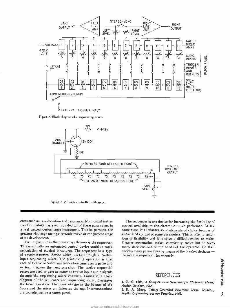
LEFT OUTPUT o
+12 VOLTS d c
470
o TART
o
o 0
OS MV
1
--- OS MV 2
o
LEFT LINE AMP
i 4
o
OS OS MV MV 3 4
CONTINUOUS /INTERUPT
STEREO -MONO RIGHT LINE AMP
RIGHT
LEFT LEVEL
o-o RIGHT
LEVEL
o OUTPUT
-e-
5
o o
OS OS MV MV 5 6
E
OS MV 7
t
o
9
o
o
t
10
o
OS MV MV-MV--
8 9 10
t I
11 -
OS MV Il
12
o
MV 12
-4
EXTERNAL TRIGGER INPUT
Figure 6. Block diagram of a sequencing mixer.
20K (RANGE)
910 +12V
DEPRESS BAND AT DESIRED POINT
75 75 75 75 75 75 75 75 75 75
"-USE 26 OR MORE RESISTORS HERE
500 (SCALE)
Figure 7. A linear controller with steps.
CONTROL OVOLTAGE
OUTPUT
GATED MIXER AMPS
AUDIO INPUTS
TRIGGER INPUTS AND OUTPUTS
ONE - SHOT MULTI - VIBRATORS
eters such as reverberation and resonance. No musical instru- ment in history has ever provided all of these parameters in a real concert -performance instrument. This is, perhaps, the greatest challenge facing electronic music at the present stage of its development.
One unique unit in the present synthesizer is the sequencer. This is actually an automated control device useful in rapid articulation of musical structures. The sequencer is a type of envelope- control device which works through a twelve - input sequencing mixer. The principle of operation is that each of twelve one -shot multivibrators generates a pulse and in turn triggers the next one -shot. The twelve sequential pulses are used to gate as many as twelve input audio signals through the sequencing mixer channels. FIGURE 6, a block diagram of the sequencer and sequencing mixer, illustrates the basic operation. The one -shots are at the bottom of the figure and the mixer amplifiers at the top. Interconnections are brought out on a patch panel.
The sequencer is one device for increasing the flexibility of control available to the electronic music performer. At the same time, it eliminates some elements of choice because of automated control of some parameters. This is often a condi- tion of flexibility and it is often a difficult choice to make. Greater automation makes complexity easier but it takes many decisions out of the hands of the operator. He then decides many parameters by means of the blanket decision - To use the sequencer, for example.
REFERENCES
1. R. C. Ehle, A Complex Tone Generator for Electronic Music, Audio, October, 1966. 2. R. A. Moog, Voltage- Controlled Electronic Music Modules, Audio Engineering Society Preprint, 1965.
www.americanradiohistory.com

a
lost Tapes ROBERT K. MORRISON
and JOHN G. McKNIGHT
Anyone that uses a tape machine sooner or later must use a test tape. The test tape is a valuable tool with certain limitations and restrictions.
The authors provide a clear understanding of the values of this instrument.
REPRODUCER TEST TAPES ARE USED by professional audio technicians to standardize the azimuth, frequency- response characteristics, and recorded levels of mag- netic sound- recording systems. Nearly 40 per cent of
test tapes are sold to sophisticated consumers, who wish to test their audio systems at least through the speaker terminals. Professionals in radio and recording and manufacturers of tape- recording equipment account for the rest of reproducer tape sales.
Test tapes (also called alignment tapes or standard tapes) make possible the practical measurement and adjustment of magnetic -tape reproducers, for recorded material must re- produce satisfactorily not only on the machine which made the original recording, but on all similar equipment.
CARE OF TEST TAPES
Tape intended for repeated use in standardization work must be properly cared for if full usefulness is to be main- tained. Tapes should not be stored in strong fields, such as those of permanent magnets or motors. Heads and tape guides should be demagnetized. When a reproducer test tape is used for continuous check -out purposes, as in production line work, age and wear often become the primary sources of inaccuracy.
Certain errors arise in test tapes after their manufacture. The most common are accidental erasure damage, mechanical deformation, magnetic damage and normal wear.
Mechanical and /or magnetic damage will destroy the ac- curacy of test tapes. Such accidental damage may occur in playing, rewinding, or storing tapes. The shorter wavelength (high -frequency) tones on the test tapes are most easily damaged.
Prolonged contact of the tape pack with one reel flange may result in irreparable edge damage. Mechanical deforma-
Robert K. Morrison is manager of the Ampex Test Tape Laboratory. John G. McKnight is staff engineer, Ampex Con-
sumer and Educational Products Division.
tion of the tape usually will damage the edge of the tape, causing uneven tracking and a constantly changing relative azimuth of the recorded tone. Edge damage can be prevented by winding the tape smoothly under moderate tension and evenly spaced between the reel flanges. High temperatures and temperature and humidity cycling aggravate mechanical
distortion of a test tape, particularly when the wind of the tape on the reel is uneven.
Effects listed as accidental damage may be small enough
to cause a type of accumulative damage not apparent from
one use of the tape. But repeated usage will result in gradual loss of accuracy. The tape surface also will wear (lose oxide),
even if the tape transport is perfect. Loose oxide also may
become welded to the tape surface, causing increased spacing
loss. When the tape passes around small radii, the mechanical
bending may cause some loss of megnetization, especially at short wavelengths. This loss depends on the tape used, but is usually about 0.5 dB at 0.5 mil wavelength.
As an example, a test tape which has been carefully han-
dled and played 50 times will likely have a loss of 0.5 to 2 dB
at 0.5 mil wavelength (15kHz at 7% inches per second).
After 100 passes, the loss may be as much as 3.5 dB at short wavelengths. Additional plays and /or slightly defective re-
producers will cause the loss to approach 5 dB or more.
Ampex prolongs the useful life of test tapes by compensat- ing for some of the losses experienced in normal usage by
recording the shortest wavelengths at a level slightly higher
than that prescribed in the National Association of Broad-
casters' Standard: a boost of 1.25 dB is used at 0.5 mil. To
reassure the purist, it should be noted that this boost is within
the manufacturing tolerance attainable and simply means
that Ampex carefully controls the flux to be on the plus side
within its manufacturing tolerance. Further, only by this means can Ampex be sure that the user ever receives a test tape with the standard flux at the short wavelength.
In the case of 7A in. /sec. tapes, the average test tape at first play will have a short wavelength flux of 0.6 dB above
the standard value, while the 15 in. /sec. test tape will be 0.3
dB high. Within the first dozen plays, the test tapes will pass
through the standard flux level and then drop below the
standard value. Recent experience with certain European test
tapes for 150 mil cassette machines has shown that, in the
www.americanradiohistory.com

case of very short wavelength tones where no boost was in- volved and where the tapes may have been purposely under - biased to facilitate the making of the level at the high -fre- quency information, the losses encountered were so great as to make the tapes worthless as tools of measurement. These tapes were at speeds of 1% in. /sec. and were demonstrated to be down 7 or 8 dB at the 10kHz region, even after careful use.
It is apparent that test tapes must be recalibrated or re- placed periodically, no matter how carefully the tapes are handled. Even though a system with short wavelengths may be adjusted to have flat over -all response, true flux response on an interchangeability basis may be difficult to obtain due to errors in the test tapes. Also, even when a system is set up to be flat on an interchangeability basis, the short wave- lengths recorded on the tapes are fugitive, just as those on the test tapes, and a flat recording at slow speed (3% in. /sec. or less) which is flat today may well be lacking high frequencies after storage or after a number of playings.
USING TEST TAPES
In order to avoid measurement errors during the use of a test tape, it is essential to observe certain special precautions, in addition to the use of ordinary good engineering practices. High- and low -frequency errors of measurement amounting to 3 to 6 dB or more are a likely result of improper procedures or the failure to observe needed precautions. Common errors of procedure cause an apparent rise of low- frequency response or a decrease of high -frequency response, or possibly both at once. Therefore, when measurement errors occur, the response will almost always fall with increasing frequency.
Test tapes may be inappropriate for use on a given system in any of the following areas: rated tape speed, flux-frequency- response (equalization), track format, and /or recorded test frequencies.
It is obvious that a 15 in. /sec. reproducer must be tested by use of a 15 in. /sec. test tape. It is not so obvious that a multiple -speed reproducer must be tested and adjusted at each of the speeds, for a response measurement at one speed guarantees nothing about the response at the other speeds. Since the NAB equalization curve is identical for both 7A and 15 in. /sec., it is commonly assumed that an adjustment at one or the other tape speed suffices for bath. Because of the 1.2 ratio of wavelengths involved this is only approximately true. Accurate response measurements require the use of both 7A and 15 in. /sec. test tapes.
FRINGING
All proposed NAB Standard test tapes, and most Ampex test tapes are recorded across the full width of the tape. A very common error is that of using.a full -track test tape to measure the low- frequency response of a multi-track repro- ducer. When these tapes are reproduced by narrower -track heads (e.g., half- track, stereo, or multiple -track heads), a low- frequency measurement error occurs because of the fringing effect - at long wavelengths (low frequencies) the reproducing head core receives effective flux from the re- corded track area outside of the area actually contacted by the reproducing head core. This error is a function of the recorded wavelength (which equals the tape speed divided by the recorded frequency), the particular design of the head shielding, and the geometry of the tape wrap over the head face. With certain heads the fringing effect may cause a rise of up to about 5 dB in the apparent low- frequency response of the reproducer. (See FIGURE 1.) Actually, it is due to the use of the wrong test tape, since a multi -track test tape must
be used for accurate low -frequency measurements of a multi- track reproducer.
No satisfactory solution has yet been found for producing test tapes for all of the various multi -track configurations of reproducers. At least 11 standard (but different) flux -fre- quency responses are used for four common speeds. If each flux -frequency response were produced in each track con- figuration, a catalog of 88 reproducer test tapes would be required. Others such as 1 in. /sec., and Ampex mastering equalization at 15 in. /sec., could undoubtedly be added. It just is not possible to manufacture, catalog, and distribute reproducer test tapes for every track configuration, because to do so would make their cost prohibitive. So reproducer test tapes are all made in the full -track configuration, but rela- tively few test tapes are made in multi-track configurations.
Another means by which fairly acceptable data on multi- track reproducers could be determined even though using a full -track test tape would be for the tape recorder manufac- turer to include in the instruction manual of each model of multi-track reproducer the response of that reproducer to a full -track test tape, when the response is fiat with the correct track- configuration of the test tape.
MECHANICAL ADJUSTMENT OF THE HEADS The gapped reproducing head is a flux collector which
gathers flux from the recorded track. Proper flux collection depends on having intimate contact and correct alignment between the recorded track and the gap area. Any imperfec- tion of this alignment or contact will result in losses at some or all frequencies. In principle, errors of contact and orienta- tion can be corrected in the reproducing equalization. The practical problems are:
1. A system with faulty contact and /or alignment is usually unstable, i.e., the response is variable during the measurement, and from one measurement to another.
2. The usual equalizer is incapable of correcting for faulty contact and /or orientation, i.e., the range and shape of equalizer responses do not generally match the response of the system in which there are contact and /or orientation losses.
3. Although faulty contact and /or orientation reduces the signal and the tape noise by approximately the same amount, the head and amplifier noises remain constant, so that the signal- to -noise ratio is usually degraded.
Because of these reasons, the contact and orientation should be mechanically adjusted in order to prevent errors
_ __======m"1,...._Ç 63 125 250 500
° FREQUENCY IN HERTZ O N
Figure 1. The fringing response rise when reproducing a full -track recording with a half-track reproducer (solid curve end a stereo reproducer (dashed curve) at 15 in. /sec. 0e is the Aux in the head core, and Ose is the short -circuit tape Aux. V
www.americanradiohistory.com

CO
in respect to a number of variables. Height of the reproducing head should be adjusted ac-
curately so that the reproducing head cores will coincide with the recorded tracks. Head height is especially critical with narrow tracks, such as four and eight -track systems. A mis-
alignment of the reproducing head, causing the recorded test tape track to contact only a portion of the reproducing head core, will cause a reduction of the reproducing core flux at medium and short wavelengths, but, due to the fringing ef-
fect, not at long wavelengths. Thus there is both a level -
setting and a frequency -response error. Misadjustments of
recording and reproducing heads also may cause recorded levels which are too high or too low, depending on the nature of the misalignment. Too high a recording level will in turn cause high distortion. Head height errors escape detection when full -track test tapes are used with multiple -track reproducers.
The gap of the reproducing head should be parallel to the gap of the recording head. Standard practice is to make both of these gaps perpendicular to the edge of the tape. These relationships will be affected by the azimuth and zenith ad- justments, and the tape guiding.
Practical azimuth adjustment is made by reproducing the azimuth adjustment section of a reproducer test tape. As
the azimuth angle of the reproducing head is changed, the
signal output will rise and fall. The adjustment must be made to the peak with the maximum output (FIGURE 2). If, before adjusting the azimuth from the test tape, the reproducing head is approximately parallel to the edge of the tape, the chances of setting to the wrong peak are greatly reduced.
Proper guiding requires that all tape guides and the front faces of the heads be parallel to the axes of the tape reels.
These, in turn, usually are perpendicular to the top plate. This adjustment of the heads is called the zenith adjustment - all axes should point upwards. If any of the elements are not parallel, any change in tape tension will cause the tape to
bow, producing an apparent azimuth change. Since in this case the azimuth depends on the tension, unstable high -fre-
quency response results. A simple technique will aid in setting the zenith adjustment:
1. Paint the face of the head with dye, using a red felt -tip
marking pen. (Wax pencil is too messy, while a layout fluid takes too long to wear off.)
2. Play a piece of scrap tape until the dye is worn off the
head face where the tape runs. Observe the wear pattern of the dye on the head face. If the
zenith adjustment is correct, the right and left edges of the wear
pattern will be parallel; if they form a V, the zenith is incorrect.
Changes of position of the tape edge also can cause the tape to bow, resulting in the apparent azimuth changes men-
tioned above. If the tape guides are too wide, the tape edge
will wander. If guides or heads have a slot worn in them, then different widths of tape will lie in them differently. This
change is especially noticeable if heads are readjusted after having been allowed to wear in an incorrect adjustment.
Very small spacings between tape and head cause large
losses: the slope is not "6 dB octave," for expotential, i.e., the
slope increases with frequency. Unintentional spacing may come from several sources.
Material (usually loose tape oxide, or loose scraps of oxide
and base material from the slitting process) may accumulate
on the head face in use, causing spacing loss. Heads should be
cleaned carefully before measurements and /or adjustments are performed.
Tape -to -head force which causes tape -to -head contact is
o tn
5 C
t'o 15
-' -20 o aJ
-25 -47r -37r -2s -7r 0 +7r +27r +37r +4,r
NORMALIZED AZIMUTH ANGLE, K9, RADIANS
Figure 2. As the azimuth angle of the reproducing head is changed, the signal output will rise and fall. In this graph, output versus
azimuth angle, where o = azimuth angle in radians, ,rK = x/X,
w = track width, X = wavelength (in the same units), and c/ 'Fsc
(s in Ke) /Ke, fore <0.2 radians (11e).
commonly obtained in professional recorders by having the heads deflect the tape path between two guides. In this case
the force which holds the tape in contact with the head is
proportional to the hold -back tension. Low contact force may
therefore be caused by a hold -back tension that is too low
because of improper adjustment, or because of the use of
large reels with the reel size (tension) switch set for small
reels (low tension). This low force again allows separation of
head and tape. In the design of a head assembly or in replacing leads in an
adjustable head assembly, it is possible to have too little wrap of the tape around the heads. For a given tape tension, head -to -tape force is a function of the wrap angle; angles of
less than about 12 degrees total deflection of the tape at each
head are unlikely to give adequate contact force for the elimination of the spacing loss.
In the machines described above which obtain tape -to-
head force by having the heads deflect the tape path between
two guides, the gap of each head must be at the vertex of the
angle so formed in order to have best tape -to -gap contact. Mention was made earlier of guiding problems due to a
head which has a slot worn in it. Such a slot causes a further difficulty: when a head wears, the cross -section usually is
stepped. The steps often cause the edge of the tape to be
lifted out of contact with the head face, with the resulting spacing loss.
EVOLUTION OF "STANDARD" FLUX -FREQUENCY RESPONSES AND LEVELS
Standardizing organizations such as the NAB have been
prolific in their recommendations, with the result that 27
different reproducer test tapes are available from Ampex, the firm that produces almost all test tapes used in the U.S.
Old standards cannot be dropped simply because a new stand- ard is adopted by one, or even all, standardizing organiza-
tions. Audio equipment and tape libraries suited to an old
standard still exist, and the manufacturer must provide corresponding test tapes for many years.
In 1953 the NAB published a description of a standard reproducer for 15 in. /sec. use, based on an idealized ferro-
magnetic reproducing head and an amplifier of specified
response. The reproducing flux -frequency response had time
www.americanradiohistory.com

constants of 3180 microseconds and 50 microseconds. At the 15 and 30 in. /sec. speeds then prevalent, the wavelength remained relatively long even at high frequencies -a 1 mil wavelength (15 kHz at 15 in. /sec.) was the shortest en- countered in general audio usage. Even without a test tape, the error might be small if the reproducing amplifier was adjusted to the specified response, and the reproducing head was assumed to be ideal. But the test tape was definitely needed to adjust head azimuth and operating level.
It was shown by experiments that a 15 in. /sec. test tape suffered very little degradation when used carefully. Carefully stored primary and secondary reference response tapes were employed to calibrate test -tape production equipment over long periods of time.
Because several different reproducing frequency responses were in use for 7.5 in. /sec. in the early 1950's, the NAB did not standardize a reproducing frequency response for this speed. Eventually the frequency response originally used for 15 in. /sec. (3180 microseconds and 50 microseconds) also became generally accepted for 7.5 in. /sec., thus becoming a standard by usage.
No mention of the recorded level was made in the 1953 NAB Standard. The Ampex Operating Level was at first deter- mined by measuring distortion, and thus would be a function
-of the particular tape used. A 15 mil wavelength signal pro- ducing 1 per cent third harmonic distortion on a selected batch of then -current 3M -111 tape became the flux reference for the Ampex Operating Level. It was soon realized that the operating level of Ampex test tapes had to be held at a con- stant absolute flux rather than at a constant distortion, so that practical compatibility of levels could be produced in the recording industry. Therefore, even though tape has changed, the Ampex Operating Level flux of test tapes has remained extremely constant to the present time. Fortunately, the tape selected in the original determination of long wave- length operating level had greater distortion at a given flux than present -day tapes. Thus the amount of distortion experi- enced today with most available tapes at operating level is less than the original 1 per cent.
A new standard was published by NAB in 1965 which re- affirmed the reproducing flux -frequency response time con- stants for 15 in. /sec. and also recognized past industry usage of the same reproducing frequency response for 7% in. /sec. However, the new NAB standard does call for a change in the reproducing frequency response time constant at 33% in. /sec. from 120 microseconds to 90 microseconds. A compromise "even value" of 100 microseconds has been proposed, also, and is now used in Ampex consumer products and Ampex stereo tapes.
AZIMUTH DETERMINATION Azimuth determination is of course crucial when using
reproducer test tapes. Correct head azimuth is obtained when the head gap is exactly at right angles to the edge of the tape. When correct head azimuth is obtained, it in turn produces a recorded track which is exactly perpendicular to the tape edge. (If tape is improperly slit, wound and /or stored, the edge naturally will be wavy and the relative azimuth will vary.)
Some very early test tapes were made with incorrect azimuth. Although not too noticeable at then -current 30 and 15 in. /sec. speeds, it was corrected because it became quite apparent at slower speeds.
Several methods are used to determine the azimuth of a recorded track. The simplest in principle is to make the recorded track visible by means of carbonyl iron powder, by
softening the binder with amyl acetate, or by using a tape viewer. A toolmaker's microscope then can be used to check the visible track's perpendicularity to the tape edge. Unfortu- nately, tape with a perfectly straight edge does not exist: therefore many measurements are required in order to deter- mine the average angle.
Until recently this method was cumbersome and not too helpful. However, greatly improved optical measurement de- vices now make this method very useful with an excellent repeatability factor. (This method also is helpful in demon- strating edge curl, which may occur when imperfect tape winding allows the tape to rest against one reel flange.)
If tape is simply turned end -for -end, the azimuth error will be in the same direction, for it does not reverse. Some means thus are necessary for producing what may be termed a mirror image. A most satisfactory method consists of these six steps (See FIGURE 3):
1. A full- track, short -wavelength signal is recorded, using a combination recording and reproducing head with an arbitrary azimuth setting. An indicator and an angular scale should be
added to the azimuth adjustment screw of the head assembly to
show the relative azimuth settings: the angle for this first record- ing should be noted.
2. After the signal is recorded, the full -track tape is rewound with the oxide surface in contact with a blank piece of tape.
3. The two tapes are then run through the machine, with a small amount of bias current applied to the second head. (The erase head is of course disconnected.) This step causes a mirror image of the original signal to be printed on the adjacent blank piece of tape.
4. The printed tape is reproduced, the head adjusted for this new azimuth, and the new setting noted.
5. The azimuth is set halfway between the two azimuth angles measured in steps 1 and 4.
6. Steps I through 5 are repeated until masters and prints both show maximum response at the same setting, thus indicating perpendicularity of the head gap to the guided tape path.
Another method for producing the mirror image involves turning the tape over and reproducing the signal through the base of the tape. The adjustment method is similar to that just explained. The problem, though, is that with the short wavelengths necessary for accurate azimuth adjust- ment, the loss of signal through the backing of the tape is so large that it is difficult to find the signal at all.
This principle of azimuth determination may be made more practical by using a two -track combination head. The two gaps must be exactly coplanar (there must be no "gap scatter "). Phase of the two signals is compared, instead of seeking maximum amplitude. If the two signals are combined out of phase, the position of correct alignment results in a very sharp null of output even when a mid -frequency signal (such as 3 kHz at 15 in. /sec.) is used. Therefore the signal amplitude can be large enough even when reproduced through the tape back.
Another method for determining azimuth has been tried using heads with a gap at the front and another at the back, and special guides for the tape. The front and back gaps of the head must be parallel to one another, and both surfaces must be lapped for good tape -to -head contact. The tape is
recorded at the front of the head, rewound oxide -out (13 wind), then reproduced by the back gap of the same head (FIGURE 4). Thus the head rather than the tape produces the mirror image. Adjustments are made as described above until per- fect agreement is achieved between back and front gaps. Guiding problems have to date made this method unsatis- factory.
www.americanradiohistory.com

o m
STEP ONE NCO
STEP TWO
STEP THREE
2 LATE OF TAPE LW I SUPPLIED
TO HEAD
STEP FOUR o
SUBSEQUENT STEPS
wECORD TAPE WITH COMBINATION HEAD AT ARBITRARY SETTING
REWIND RECORDED TAPE IN CONTACT WITH A BLANK TAPE ONTO ONE REEL ( OXIDE TO OXIDE CONTACT),
PASS TWO TAPES IN NORMAL MODE OVER HEAD WITH BIAS CURRENT SUPPLIED TO HEAD.
REPRODUCE 'PRINTED' RESULT WHICH IS A MIRROR IMAGE MAIE PARTIAL CORRECTION TO HEAD AZIMUTH.
CONTINUE CORRECTION UNTIL RECORDED MASTERS AND PRINTED RESULTS AGREE WITH ONE AZIMUTH SETTING,
Figure 3. Azimuth determination using the master and transfer print method.
CALIBRATION OF THE FLUX VERSUS FREQUENCY
Procedures detailed in the 1965 NAB standard are generally followed for calibration of the reproducing channel used in making reproducer test tapes. First the response of the re- producing head is determined along with the electronics from a "constant flux available" input. (A flux -inducing loop is attached to the front gap of the head, and a constant current signal vs. frequency is applied through the loop.) The ampli- fier can then be adjusted to provide the correct response for the head, assuming a flat wavelength response. See FIGURE
5 and 6.) (In this measurement, resonance effects of the head and cable are included. It simplifies matters, if the playback head resonates well outside the bank of interest; this requires a low- inductance head, with fewer turns of wire than usual.) A de- emphasis network may be used with this flux -inducing
BASE SIDE dnnp\PTTTTTn.
I\111111111111111\111 UUT1UU111%Ul T \
COMBINATION RECORD- PLAYBACK HEAD
REAR GAP
FRONT GAP
GAPS PARALLEL
Figure 4. Azimuth determination using front /back gap method. Above, the recording is made on the front face of the head. Playback is accomplished on the back gap. The head is adjusted until the recording made on the front gap plays back in agreement with the rear gap.
method after the reproducing amplifier to produce a flat read- ing on a voltmeter when the reproducer response is correctly adjusted to the appropriate standard. A different response is of course needed for each of the many standard curves in use.
Wavelength response errors will exist with a practical head, and these must be measured and taken into account. Gap losses and contour effects are measured as outlined in Annex C of the 1965 NAB Standard. These measurements are some- what involved, and it is best to doublecheck them. Additional- ly, several known heads should be measured for later cross reference.
A curve may be drawn showing the deviation from ideal of a particular reproducing system after the losses inherent in the reproducing head are determined. A recording then may be made which will reproduce in agreement with the calibra- tion curve. In other words, test tape should ideally play back with the same response as the calibrated reproducing system. The inherent deficiency of the calibration reproducer must be known so that the corrections will be applied to the cali- brated reproducer, not to the test -tape recording.
After a system is calibrated, a tape may be made for use in adjusting other test -tape production machines, for test -tape production on a comparative reference basis. Each machine must produce tapes which have recorded flux identical to that of the tape made on the calibrated system. In production
0
Ñ -10
-20
° -30 0.063 0.125 0.25 0.5 LO 2.0 4.0
/). (FREQUENCY
1.. --M -M..... LIMS-711 7I1I ..... I. MIs .M7/M111 11 -MI 71--17.. I :. 7 IP Ì
IAt . I A117717 M.,EII M715-S17 MOMS .-77-.1 51 iiiiii Ì .--.-.' MIMI 1.771111 MINN M MI 1.77-I -- - -I leli \7 M.- 7 w/01117M r"M.s 7 A77 MII /N 1- IA IIA\
Figure 5. (Left) The theoretical short wavelength response of a reproducing head with a
long gap, where I is the mechanical gap length. Figure 6. (Right.) The theoretical long wave- length response of an unshielded reproducing head with rectangular pole pieces, where L
is the length of the head core face and X is the recorded wavelength.
I 2 4 8
(FREQUENCY -)
www.americanradiohistory.com

practice, several tapes are made on the calibrated reproducer and used as setup tapes. But it is very important to note that setup tapes do not last long, and must be recalibrated frequently on the original test setup or else replaced entirely.
SUMMARY Although the reproducer test tape provides the most satis-
factory means known for measuring and adjusting the azimuth and frequency response of tape reproducers, there are num- erous opportunities for making errors in the measurements. If care is taken in performing the measurements and these errors are avoided, measurements with a test tape should give accurate indications of the frequency response of a re- producer. Used correctly, test tapes are a valuable addition to both professional and amateur audio systems.
Readers seeking additional information on Ampex test tape applications will find their 12 -page brochure Test Tape Applications useful. It is available without charge by circling number 100 on the reader service card bound into the back of this issue.
Mechanical
Engineering Continuing demand ated in our City on Duties activities gineering product ates in duct design BSME tape transport subjects, braking, Your complete Rutman, Bay Road, Ampex ployer.
Design
Manager and increasingworld
for Ampex products this excellent growth Corporate office in
the San Francisco include the supervision
of the audit mechanical group and working
marketing and other formulating advanced
concepts with 10 years' experience
design and i.e., tape reeling,
and speed control. Resume may be forwarded
confidence to Employment Office,
Redwood City, is an equal opportunity
-wide has cre- position
Redwood Peninsula.
of en-
with associ-
pro-
in related
guiding,
in Mr. R. E.
2655 California.
em-
AMPEX
Best Value Audio Instruments
Come from Heath!
NEW Heathkit IM -48
Audio Intermodulation
Analyzer
Kit
$6900
Three Audio Test Instruments in one: efficiently com- bines the function of AC VTVM, Wattmeter, and IM Analyzer Built -in high and low frequency signal sources for IM tests Built -in load resistors for 4, 8, 16 and 600 ohms Easy to read meter Complete instructions included
NEW Heathkit IM -58
Harmonic Distortion Meter
Kit
$6500 ro ri e4 Accurately measures Harmonic Distortion at any fre-
quency between 20 and 20,000 Hz as low as 1% full - scale reading Meter scales calibrated in volts RMS, % distortion, and dB Measures noise levels down to -60 dBm Quality components for precision measure- ments Easy to assemble and operate Full instruc- tions included
. -is
NEW
Kit $3950 Wired $5495 A compact instrument for au-
dio design and development 10 voltage ranges - from 0.01 to 300 volts RMS full scale Ex- tended frequency response, ±1 dB from 10 Hz to 500 kHz 10 megohm input impedance for high accuracy Calibrated scale for audio measurements VU type ballistic meter damping
Heathkit 1M -38 Lab AC VTVM
HEATH COMPANY, Dept. 74.11 Benton Harbor, Michigan 49022
Please send my FREE 1969 Heathkit Catalog.
Enclosed is $
Please send model (s)
Name
plus shipping
Address
City State Zip Prices & specifications subject to change without notice. TE -193
L
Circle 27 on Reader Service Card
www.americanradiohistory.com

04
\ew Products and Service
PORTABLE SOUND SYSTEM
ROCK MICROPHONE
Here is a microphone specifically de- signed for the hard -rock music field. The D -1000E is capable of handling the large sound pressures developed in this music field. The mic is close- talking and eliminates instrumental interference ordinarily annoying to vocalists. The housing is designed to withstand un- commonly rough treatment. A mode selection switch (sharp, medium, bass) attenuates the mic's response to suit particular needs. Mfgr: AKG Price: $60 ($75 with transformer and
silent on /off switch) Circle 57 on Reader Service Card
"fhe A104 is capable of producing 145 watts of continuous power. It couples a 1202A "The Voice of the Theater" speaker system with a 1203A power speaker. The 1202A is driven by a 1200A control console, while the 1203A has its own power amplifier. The mixer power amplifier is capable of con- trolling up to five independent input signals. It is also capable of 60 watts continuous on its own. Reverb is built - in with a switchable, individual control for each channel. The speakers are designed for extra power loads. They offer extremely high efficiency, wide dynamic range, and 85 watt power - handling capability. All units of the system are covered in vinyl lamination offering a measure of protection against rough handling. Mfgr: Altec- Lansing Circle 60 on Reader Service Card
THUMBWHEEL FADER
Depending on networks, a total of twenty -three steps is available (twenty - two plus off) in this new attenuator. Standard configurations include a balanced potentiometer, unbalanced bridged T (ten step), or two unbalanced ten -step pots. Scale illumination is avail- able as an option. Non -warping glass fiberboard connectors are available or the unit can be supplied with a polarized nine -pin connector. Either connector is at the rear of the unit. Noise -free con- tacts are used to reduce noise level and virtually eliminate cleaning and mainte- nance. Mounting centers are 3% inch. Mfgr: Painton, Inc. Circle 51 on Reader Service Card
CUTTERHEAD This fourth generation of Neumann stereo cutterheads brings technical char- acteristics long sought by the recording industry. The SX -68 is made to satisfy the most stringent demands for smooth response, low distortion, high channel separation, high recorded level, and ex- treme ruggedness. As with its predeces- sors, this head is fitted for helium cool- ing. Important characteristics are: sec- ondary resonance above 75 kHz; high feedback capability with a reserve to prevent oscillation resulting in less than ±1 dB frequency response deviation, and extremely low distortion over the entire audio range; channel separation is 35 dB over the full range; vertical cut- ting angle is 15 °; and construction is rugged. An important design parameter is the ability to cut (with helium cool- ing) lateral velocities at 10 kHz of 40 cm /sec for ten seconds, or 26.5 cm /sec continuous sine wave. Mfgr: Neumann (distributed by Gotham
Audio Corp.) Circle 58 on Reader Service Card
www.americanradiohistory.com
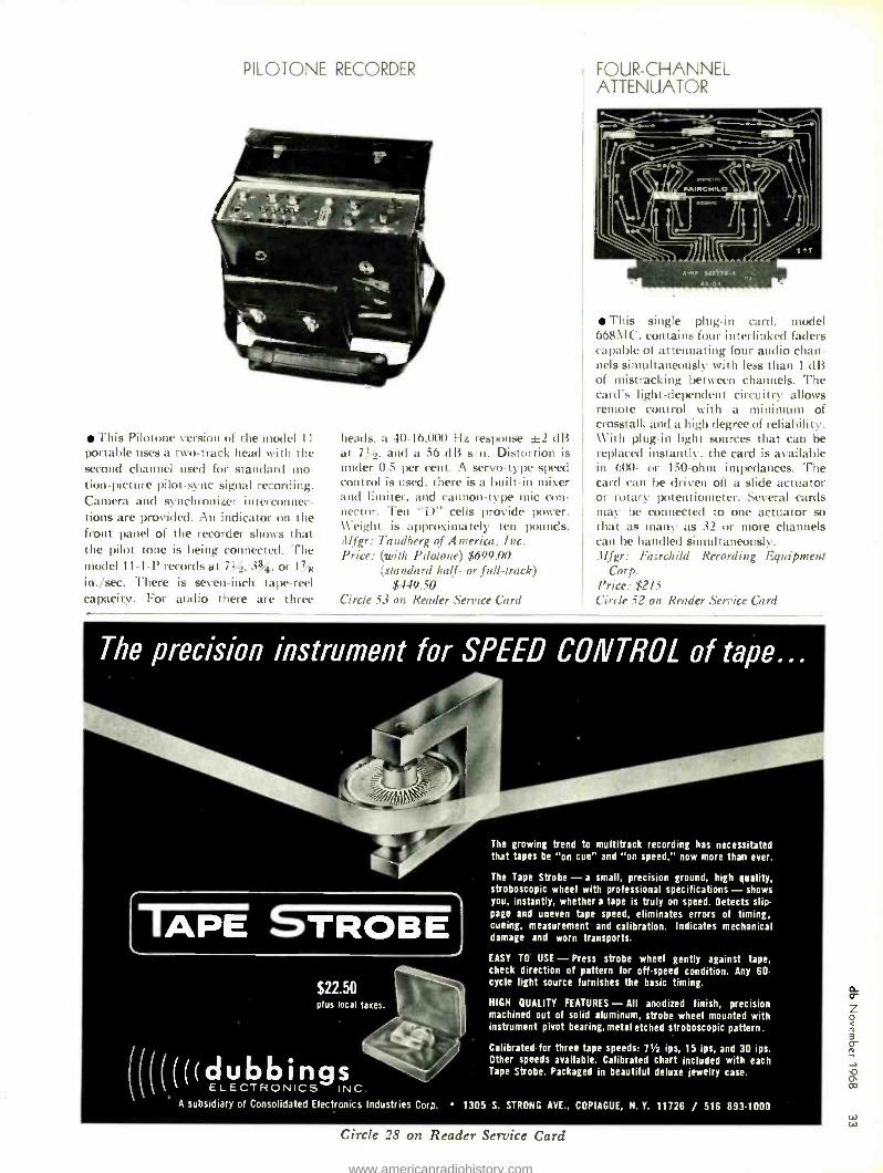
PILOTONE RECORDER
This Pilotone version of the nude) 11
portable uses a two -track head with the second channel used for standard mo- tion- picture pilot -sync signal re,ording. Camera and synchronizer interconnec- tions are provided. An indicator on the front panel of the recorder shows that the pilot tone is being connected. The model 11 -1 -1' records at 7%, 33%, or 17s in. /sec. There is seven -inch tape-reel capacity. For audio there are three
heads, a 40- 16.000 Hz reslxmse ±2 dB at 7! 2. and a 56 dB s 'n. Distortion is under 0.5 per cent. A servo-type speed control is used, there is a built -in mixer and limiter, and cannon-type mic con- nector. Ten "D" cells provide power. Weight is approximately ten pounds. .Mgr: Tandberg of America, Inc. Price: (with Pdolone) $699.00
(standard half- or full- track) $449.50
Circle 53 on Reader Service Card
FOUR- CHANNEL ATTENUATOR
This single plug -in card, model 668110, contains four interlinked faders capable of attenuating four audio chan- nels simultaneously with less than 1 dB of mistracking between channels. The card's light -dependent circuitry allows remote control with a minimum of crosstalk and a high degree of reliability. With plug -in light sources that can be replaced instantly, the card is available in 600 - or 150 -ohm impedances. The card can be driven off a slide actuator or rotary potentiometer. Several cards may be connected to one actuator so that as many as 32 or more channels can be handled simultaneously. .Ilfgr: Fairchild Recording Equipment
Corp. Price: $215 Circle 52 on Reader Service Card
The precision instrument for SPEED CONTROL of tape...
ÌAPE SE $22.50 plus local taxes.
/II/(((((dubbings 1 ELECTRONICS INC.
The growing trend to multitrack recording has necessitated that tapes be on cue" and on speed," now more than ever.
The Tape Strobe - a small, precision ground, high quality, stroboscopic wheel with professional specifications - shows you, instantly, whether a tape is truly on speed. Detects slip- page and uneven tape speed, eliminates errors of timing, cueing, measurement and calibration. Indicates mechanical damage and worn transports.
EASY TO USE - Press strobe wheel gently against tape, check direction of pattern for off -speed condition. Any 60- cycle light source furnishes the basic timing.
HIGH QUALITY FEATURES - All anodized finish, precision machined out of solid aluminum, strobe wheel mounted with instrument pivot bearing, metal etched stroboscopic pattern.
Calibrated for three tape speeds: 71 ips, 15 ips, and 30 ips. Other speeds available. Calibrated chart included with each Tape Strobe. Packaged in beautiful deluxe jewelry case.
A subsidiary of Consolidated Electronics Industries Corp. 1305 S. STRONG AVE., COPIAGUE, N.Y. 11726 / 516 8931000
Circle 28 on Reader Service Card w w
www.americanradiohistory.com

The db Bookcase
As a service to our readers we are pleased to offer these books from prominent tech- nical publishers. All prices listed are the publishers' net. Shipping charges are included. Use the coupon at the bottom of the page or give the complete title, author and coupon number. Be sure to indicate quantity on the special instructions line if more than one copy of a title is wanted. Full payment must accompany your order. We cannot ship c.o.d. Checks or money orders should be made payable to Sagamore Publishing Com- pany, Inc. Because of the time required to process orders, allow several weeks for the receipt of books.
Broadcasting RADIO BROADCASTING edited by Robert L. Hilliard. Each of the five chapters has been written by a prominent educator with an extensive background of practical experience in commercial and edu- cational broadcasting The areas covered in- clude: management and programming, oper- ating and studio facilities, producing and di- recting, writing, performing. For those of you who want to, or must, operate on both sides of the control room, this is virtually required reading. 190 pages; 6y x 9M; indexed; clothbound. $6.95 ($8.35 in Canada) Circle 2 on Coupon Below
PLANNING THE LOCAL UHF -TV STATION by Patrick Finnegan. 1965. An informative guide for the planning, building, and opera- tion of a small- market, UHF -TV station. Based on the author's lengthy experience in the technical operation of such a station, it explains equipment, layout, and building costs that apply to the small studio (one -man
control room operation) with a heavy film
schedule. A valuable aid for the station owner, manager, engineer and layman inter- ested in this medium. 328 pages; 6 x 9; illus; clothbound 110.00 ($11.95 in Cenada) Circle 17 on Coupon Below
r-
How To General Audio
HOW TO BUILD SPEAKER ENCLOSURES by Alexis Badmaieff and Don Davis. A thor- ough and comprehensive "do- it- yourself' book providing a wealth of practical and theoretical information on the "whys" as
well as the "hows" of constructing high - quality, top -performance speaker enclosures. Contains detailed drawings and instructions for building the various basic enclosures. In- cludes infinite -baffle, bass -reflex, and horn projector types as well as several different combinations of these. The book covers both the advantages and the disadvantages of each enclosure type and includes a discus- sion of speaker drivers, crossover networks, and hints on the techniques of construction and testing. Written and compiled by two of the nation's leading authorities in the field of acoustical engineering. 144 pages; 53,6 x
softbound. $3.50 ($4.25 in Canada) Circle 3 on Coupon Below
PRACTICAL PA GUIDEBOOK: HOW TO INSTALL, OPERATE AND SERVICE PUBLIC ADDRESS SYSTEMS by Norman H. Crowhurst. 1967. This book gives all the basics needed to become a suc- cessful PA operator, in any situation where the reinforcement, relay, or distribution of sound can provide a service. It shows how to properly install, operate and service public address systems. All aspects of the subject, from survey to the selection of appropriate equipment, to installation, to routine opera- tion and the maintenance of a finished sys-
tem, are covered. Attention is given to solv- ing problems encountered in providing suc-
cessful service. The book's systematic and practical approach makes it highly useful to radio -TV servicemen, hobbyists, and PA equipment manufacturers. 136 pages; 6 x 9; illus; softbound. $3.95 ($4.60 in Canada) Circle 15 on Coupon Below
CLOSED CIRCUIT TV SYSTEM PLANNING by M. A. Mayers and R. D Chipp. 1957 This book discusses in detail the vitally im-
portant and rapidly expanding concept of closed circuit TV systems, its utility and func- tioning. This book is not an engineering or a
technician's text - it is written for manage- ment. It explains and illustrates the kind of systems that are available and their applica- tions. 264 pages; 83 x 11; illus; clothbound. S10.00 ($11.95 in Canada) Circle 16 on Coupon Below
Sagamore Publishing Company, Inc. 980 Old Country Road, Plainview, N.Y. 11803 Please send me the books I have circled below. My full remittance in the amount
of $ is enclosed. N.Y. State residents add 2% sales tax.
1 2 3 4 5 6 7 8 9 10 11 12 13 14 15 16 17 18 19 20 21 22
23 24 25 26 27 28 29 30 31 32 33 34 35 36 37 38 39 40
Name
Street Address
City State Zip
rn rn , Special Instructions J
l
THE TECHNIQUE OF THE SOUND STUDIO by Alec Nisbett. This is a handbook on radio and recording techniques, but the principles described are equally applicable to film and television sound. It describes how the high- est standards may be achieved not only in the elaborately equipped studio but also with simple equipment out on location. 264 pages; 60 diagrams; glossary; indexed; 53 x 8M; clothbound. $10.50 ($11.95 in Canada) Circle 1 on Coupon Below
MICROPHONES by A. E. Robertson. 1963. This book, pri- marily written as a training manual for tech- nicians, will also prove valuable to all users of quality microphones whether for broad- casting, public address systems, or recording of all types. There is now an almost bewilder- ing array of microphones of differing charac- teristics, and new designs are constantly be- ing produced. The author makes no attempt to catalogue these but concentrates mainly on the principles of operation. He only de- scribes actual microphones if they illustrate an important feature or have some historic significance. The book is intended for the user rather than the designer; mathematics have been omitted from the main body of the text. 359 pages; 6 x 9; illus.; clothbound. $12.75 (S15.40 in Canada) Circle 13 on Coupon Below
Electronics and Mathematics
ELECTRONICS MATH SIMPLIFIED by Alan Andrews. For the engineer, student, or technician who requires a knowledge of mathematics as it pertains to electronics. Covers the subject in a logical, clear, and concise manner, using dozens of examples related specifically to electronics. Particu- larly suited for use as a textbook in any school or other training program involving the study of electronics, the book has been especially prepared to coincide with studies leading to 2nd- and 1st -class FCC Radiotele- phone licenses. (2 vols. in slipcase) $7.95 ($9.95 in Canada) Circle 11 on Coupon Below
MATHEMATICS FOR ELECTRONICS ENGINEERS & TECHNICIANS by Norman H. Crowhurst. This book is writ- ten to help the advanced technician and the engineer bridge the gap between "book learning" and practical experience. It is not about mathematics but about how to use
mathematics in electronics. A unique pro- grammed method shows not only how to ap- ply textbook math towards the solution of any electronics problem but also teaches how to think in the best way for solving them. Much emphasis is placed on correcting mis-
conceptions commonly held by technicians. The book begins with Ohm's and Kirchhoff's laws and goes on to selective networks, properties of coils and transformers, feedback circuits, etc. 256 pages; 53 x 8M (hard- bound). S6.95 ($8.35 in Canada) Circle 4 on Coupon Below
www.americanradiohistory.com

HANDBOOK OF ELECTRONIC TABLES & FORMULAS, (3rd Edition) A one -stop source for all charts, tables, for- mulas, laws, symbols, and standards used in electronics. Devotes complete sections to items of interest to service technicians and to circuit design data. Includes a 8 -page, full - color fold -out chart showing latest FCC allo- cations for the entire frequency spectrum. 232 pages; 5% x 8 %; hardbound $5.50 ($6.60 in Canada) Circle 8 on Coupon Below
Test and Maintenance INTERMODULATION AND HARMONIC DISTORTION HANDBOOK by Howard M. Tremaine. A complete refer- ence guidebook on audio signal intermodu- lation and harmonic distortion. 172 pages; 5% x 8 %; softbound. $4.25 ($5.25 in Canada) Circle 9 on Coupon Below
Circuitry and Components PASSIVE AUDIO NETWORK DESIGN by Howard M. Tremaine. A complete and comprehensive guide to the design, con- struction, and testing of all types of attenu- ators, equalizers, and wave filters for the practicing audio technician or engineer. This authoritative text is one of the few written on the subject, and requires only nominal mathematical background. Written in easy - to- understand language, the content presents the basic design, construction, and testing considerations without the confusion often associated with passive networks. 288 pages; 5% x 8%y: softbound. S5.50 ($6.45 in Canada) Circle 5 on Coupon Below
TRANSISTORS FOR AUDIO FREQUENCY (AUDIO- FREQUENCY AMPLIFICATION) by Guy Fontaine. 1967. This systematic and detailed treatment of the application of tran- sistors in audio -frequency amplifiers shows how the published transistor characteristics are related to the principles of design. To as- sure clarity, the figures are rendered in sev- eral colors and placed opposite the related text. Simple equations reinforce the lucid ap- proach. An ideal textbook or reference on the subject for engineers and advanced techni- cians. 384 pages; 5% x 8; illus.; clothbound. $7.95 ($9.55 in Canada) Circle 12 on Coupon Below
ACOUSTICAL TESTS AND MEASUREMENTS by Don Davis. Provides a solid understand- ing of the entire subject of acoustical meas- urements; based on actual field test work, using commercial equipment. Contains prac- tical, time- saving solutions to actual problems encountered in the field; minimum math is re- quired for understanding. The author is an expert in this field, and an authority on audi- torium acoustics. An invaluable book For phone company special service engineers, plant maintenance engineers, communica- tions engineers, noise control specialists, ar- chitectural engineers, broadcast engineers and technicians, hi -fi fans and students. 192 pages; 5% x 8 %; hardbound. $6.95 ($8.35 in Canada) Circle 7 on Coupon Below
DESIGN OF LOW -NOISE TRANSISTOR INPUT CIRCUITS by William A. Rheinfelder. 1964. Written for students as well as circuit design engi- neers interested in low -noise circuit design. Throughout, the book gives a multitude of time- saving graphs and design curves for the practical circuit designer. Simple derivations of all important formulas are also presented to help the reader obtain a deeper insight into the fundamentals of practical low -noise design. 128 pages; 6 x 9; illus., clothbound. $5.50 ($6.50 in Canada) Circle 14 on Coupon Below
Reference
New 17th Edition of the famous RADIO HANDBOOK Tells how to design, build and operate the latest types of amateur transmitters, receiv- ers, transceivers, amplifiers and test equip- ment. Provides extensive, simplified theory on practically every phase of radio. Broad coverage; all original data, up to date, com- plete. 847 pages. $12.95 ($15.50 in Canada) Circle 10 on Coupon Below
Classified Looking for a qualified professional to fill a job opening? Trying to sell some audio equipment privately? Want to get an audio engineering position in another city?
USE db CLASSIFIED ... A UNIQUE NEW EMPLOYMENT AND
EQUIPMENT EXCHANGE FOR THE WHOLE AUDIO INDUSTRY
db THE SOUND ENGINEERING MAGAZINE now offers a classified advertising section to firms and individuals in all areas of audio - recording, commercial sound, broadcast- ing, manufacturing, film and tv sound, etc. Closing date is the fifteenth of the second month preceding the date of issue. Send copy to: Classified Ad Dept. db THE SOUND ENGINEERING MAGAZINE 980 Old Country Road Plainview, New York 11803
FOR SALE
SOLID -STATE 50 WATT RMS plug -in d.c. thru 25 kc operational power amplifier kit, model 440K. Price $30.00. Send for free catalog and 50 operational amplifier appli- cations to: Opamp Labs. 172 So. Alta Vista Blvd., Los Angeles, California 90036.
SCULLY TAPE RECORDERS - One to twelve track. Two, four, and eight track models in stock for immediate delivery. SCULLY LATHES - Previously owned and rebuilt. Variable or automatic pitch. Com- plete cutting systems with Westrex heads. MIXING CONSOLES - Custom designed using Electrodyne, Fairchild and Universal Audio modules. From $4000.00. Wiegand Audio Laboratories, 3402 Wind- sor Road, Wall, New Jersey 07719. Phone: 201 681 -6443.
AUDIO EQUIPMENT for churches, schools, recording studios, radio and t.v. stations. New and used. Trade -ins accepted. AM- PEX, BOGEN, ELECTRO- VOICE, SHURE, SCULLY, and many others. Free lists. Boynton Studio, 118DB Brook St., Scarsdale, N. Y. 10583.
EMPLOYMENT
JUNIOR RECORDING ENGINEER seeking position in New York /New Jersey area. Have extensive field recording experience and technical knowledge in professional audio equipment. Being discharged from the service in January. Write: Vincent Guiffre, 31 Merrymount St., Staten Island, N.Y. 10314
SERVICES
CUSTOM STYLUS AND CARTRIDGE re- tipping and repair service. Replacement styli (playback, not cutting). Only source in U.S. for true grain- oriented diamonds. (4 -100X longer life and 2 -4X higher polish.) Special and experimental stylus applications. Inter- national Audio Stylus Corp., 111 -D Lake Ave., Tuckahoe, N.Y. 10707. Telephone 914 SP9 -1297. (If phoning, ask for Mr. Gerald Shirley.)
DON'T BE AN AUDIO DROPOUT! See BROADCAST EQUIPMENT REBUILDERS for your tape cartridge rewinding needs. Route 8, Box 718, Fayetteville, N.C. 28304. (919) 425 -7332.
www.americanradiohistory.com

rñ
Pcope1 Placcs, appcníngs
t Benjamin B. Bauer, an audio re-
search scientist for CBS Laboratories, has been elected president of the Audio Engineering Society :for the coming year. Mr. Bauer has been responsible for many innovations in audio and acoustics, including highly advanced microphones for the broadcast field, phonograph sound pick -up devices and tape- recording heads. He has spear- headed many CBS Laboratories de- velopments including the recent intro- duction of a loudness -level monitor which analyzes sound frequencies and converts them into indications of loud- ness. The device then adjusts them to a pleasing level for radio and television broadcasting.
Frederick B. Bundesmann has been named broadcast systems sales manager by Philips Broadcast Equipment Corp., manufacturer of Norelco closed - circuit and broadcast -television equip- ment. The announcement was made by Anthony R. Pignoni, director of mar- keting. Mr. Bundesmann formerly was eastern regional manager, F & M Sys- tems Company, and prior to that was a sales engineer for MGM Telestudios. In his new post he will coordinate the efforts of the company's field sales en- gineers on major broadcast systems installations.
Recorded Publications Labora- tories of Camden, New Jersey has com- pleted installation of a new automatic stereo facility for the production of stereo disc masters. According to David Goodman, executive vice president of the firm the new equipment was custom designed and constructed by Dr. Georg Neumann in West Berlin and incor- porates the new Westrex 3D stereo disc cutting system as well as Ampex play- back equipment for program input. The system is computor controlled to handle every faca of the audio and mechanical requirements of disc mastering. Accord- ing to Mr. Goodman, the combination of a skilled mastering technician and the computer system assure high standards in consistency and quality of the finished masters.
An announcement by Walter Stan- ton, president of Stanton Magnetics Inc. calls attention to the return of George Petetin to the organization. Mr. Petitin is a former employee of Pickering (pert of the Stanton group), having served as dealer sales manager from 1950 to 1962. In 1962 he moved to Reeves Soundcraft as distributor sales manager. Since January of this year he has been manager of the special products division of JBT Instruments, Inc. In his new position he will fill the post of sales manager of Stanton Magnetics Inc. According to Mr. Stanton this move is one of several designed to broaden the marketing approach of Stanton Mag- netics Inc. and Pickering and Company, Inc. C. Ray Bennett has been ad- vanced to the newly created post of corporate sales administrator. Stanton Magnetics Inc. is a supplier of profes- sional products for the recording and broadcast industry.
From Fairchild Recording Equip- ment Corp. comes word that David Bain has been appointed as manager of application engineering, a newly created post. In a statement by Edwin J. Everitt, president of the firm, Mr. Bain's addition to the staff is called another major step in the total expan- sion program of the firm. Mr. Bain has an extensive background in professional audio. As a partner in the firm of Joseph & Bain, he acted as sales representa- tive for professional and broadcast - equipment firms. Prior to that he was general manager of the product division of the Muzak Corporation. Before that he was in the broadcast and tele- vision division of RCA serving in vari- ous sales and management posts in Camden, Chicago, Kansas City, and Washington. He has also been chief engineer of several radio stations.
Several moves have been announced at Ampex divisions. Charles S. Dolk has been named marketing manager for the Ampex Corporation industrial and educational products division head- quartered in Park Ridge, Illinois. In his new post Mr. Dolk will be responsible for marketing sales, and advertising of the division's line of closed- circuit videotape recorders, t.v. cameras, and associated equipment.
From Redwood City, California comes word that Lawrence Weiland, general manager of the Ampex Corporation video products division, has been elected a vice president of the corporation. Mr. Weiland has been with Ampex since 1960 when he joined as manager of video engineering. He also was video market- ing manager of the audio -video group prior to assuming his present position.
www.americanradiohistory.com

-\ ITI
wPllf ILN FOSS A[O..SICC.
/ 90ae
ask yourself
a serious
Question:
can't you huild a hotter amplifier
than you can buy?
You sure can! Koss -Acoustech will provide you with all you need for a more advanced, more sophisticated solid state amplifier kit (or pre -amp, tuner or receiver) than any unit now available in wired form. You'll receive clear, easy -to- follow instructions for every move and your own quality control check -out. Only with Koss -Acoustech "state of the art" kits can you have an amplifier with so nearly perfect square -wave transmission, such incredibly low IM distortion, and a frequency response out to 300,000 Hz! So you see, it really pays to use your kit -building skill. It's the only way to better equipment. For complete information on Koss -Acoustech amplifier, pre -amp, tuner and receiver kits, write now or ask your hi fi dealer.
KOSS KOSS ELECTRONICS INC. 2227 N. 31st Street Milwaukee, Wis. 53208
Export: Koss Electronics S.r.l. Via Bellini 7, 20054 /Nova Milanese, Italia
Export Cable: Stereotone
HIGH FIDELITY
Circle 12 on Render Service Card
www.americanradiohistory.com

Creative Mixing from the
Innovators at Norelco
.. 1 s = =
ri á \ .,
% i = i vÚÜV`` r - i ! l! 41 41
Meet our third generation MD -Range Audio Mixing Desk. Another innovation from the company whose broadcast system capability is relied on by all three networks, independent and educational broadcasters.
Extremely compact, plug -in modular construction. Solid -state printed circuit electronics. Greater flexibility and integrity. It's what you expect from the Inno- vators, and precisely what you need in a radio or TV studio, broadcast van, large theater or film and sound dubbing studio. Norelco's MD -range Audio Mixing Equipment is, in fact, the most advanced sound control equipment in its class.
The MD Series features true current dependent mixing. You can add input blocks to expand capacity without readjusting bus bar impedance and interme- diate amplifiers which you must do with voltage- dependent mixing.
Each channel can be switched to as many as four outputs in any combination simultaneously without crosstalk. There's a separate reverberation return master channel and four extra inputs for stereo and two -channel monitoring.
A pre -listening push button for each channel permits you to check inputs instantly without interfering with the program in any way. Available in four stand- ard models with as many as twenty -four inputs for twelve active channels.
Let our engineers help you select a mixer for your specific system require- ments. Our complete line of audio mixing units includes a Portable 12- Channel System suitable for studio or field; an 8- Channel Solid -State Mixer for remotes or small studios; a light compact 4 -Chan- nel Mixer that may be battery operated. Whatever your audio needs, there is a sound reason why the Innovators at Norelco meet them best. 299 Route 17, Paramus, N. J. 07652 201/262 -7300
(:i1(1e l î on Reade .Set '!(e (:nr(1
Noreko PHILIPS BROADCAST
EQUIPMENT CORP.
www.americanradiohistory.com