Embed Size (px)
Citation preview
THE ROLE OF VORTEX WAKE DYNAMICS IN THE FLOW-INDUCEDVIBRATION OF TUBE ARRAYS
Nicholas KevlahanDepartment of Mathematics & Statistics
McMaster UniversityHamilton ON L8S 4K1
ABSTRACTPotential flow and two-dimensional Navier–Stokes cal-
culations are used to investigate the role of vortex sheddingin the non-resonant flow-induced vibration of periodic tubearrays. This dual approach untangles the effects of potentialand vortical flow. The negative damping theory is shown to beinconsistent with the Navier–Stokes simulations, and allowingonly a single degree of freedom in tube motion significantlyoverestimates the critical velocity. In contrast, Navier–Stokessimulations which allow all tubes to move in both the trans-verse and streamwise directions give results in good agree-ment with experiment. Somewhat surprisingly, potential flowcalculations including an artificial phase lag between fluidforce and tube motion give reasonably accurate results for awide range of phase lags. This may be due to the fact that themost unstable mode at onset appears to be streamwise anti-phase (not whirling), as observed in the potential flow case.
INTRODUCTIONIn this paper we consider the case of the free vibration
of circular cylinders in a tightly packed periodic square inlinearray of cylinders with a pitch to diameter ratioP/D = 1.5.The role of vortex wake dynamics in the flow-induced vibra-tion of tube arrays is still not well understood, particularly forinline arrays (whose wake dynamics are characterized by in-complete vortex shedding). Two principal theories have beenadvanced to explain the vibrational instability of such tubearrays:negative damping (which requires only that one tubemove relative to its fixed neighbours), andstiffness controlled(which requires that adjacent tubes move out of phase in a“whirling” mode). We use appropriate numerical simulationsto investigate both scenarios.
If a single cylinder free to vibrate in the transverse direc-tion is surrounded by fixed cylinders (a common experimentalconfiguration), the flow asymmetries caused by the movementof the central cylinder relative to its neighbours generates a“galloping” type instability in addition to the pure vortex-induced vibration of the isolated cylinder case. Although thisgalloping is often treated as a purely potential flow instabil-ity mechanism (except in the resonant vortex shedding case
U∗ ≈ 1/St), the necessary forces and phase lag are determinedby the interaction of the wake of the moving cylinder with thesurrounding cylinders.
Paidoussis & Price (1988) developed a simple negativedamping theory of fluidelastic instability in tube bundles byassuming a phase lag between the cylinder motion and totalfluid force. (If there is no phase lag, the dynamics is purely po-tential and only a non-oscillatory divergent instability is possi-ble.) Consider an array of cylinders as in figure 1(a) in whichthe central cylinder is free to vibrate in they−direction trans-verse to the mean flow (all other cylinders are fixed). If theresponse of the cylinder is modelled as a simple harmonic os-cillator, the equation of motion for the vibrating cylinderis
y+δπ
ωN y+ω2N y =
Fy
m, (1)
whereωN is the natural frequency,m is the mass (includingadded mass) andδ is the logarithmic decrement (i.e. mechan-ical damping). For small displacements quasi-static theorygives the total fluid force as
Fy(t) ≈12
ρU2DdCL
dyy(t − τ)−
12
ρUDCD y(t), (2)
where the first term is the force due to the cylinder displace-ment and the second term is the fluid damping.CL andCDare respectively the lift and drag coefficients at equilibrium,whereCL = 0 due to symmetry. Note that we assume atimelag τ between the cylinder displacement and the resultingforce. This time lag leads to an additional drag term sincey(t)is assumed to be sinusoidal. Substituting (2) in (1), assum-ing thatτ ≈ µ D/Ug ≪ 1 (whereUg is mean velocity in thegap between the cylinders andµ ∼ O(1)) and setting the totaldrag equal to zero gives the critical velocity for the negativedamping instability,
Ug
fND= U∗
crit =
[
4−CD −µDdCL/dy
](
mδρD2
)
. (3)
1

This expression suggests thatdCL/dy must be large and neg-ative for instability. This is consistent with vortex sheddingflows since a positive vortex is shed from the lower side of acylinder when its displacement is maximal. Note that in prac-tice the phase lag parameterµ and the linear force coefficientsCD anddCL/dy must be measured experimentally.
On the other hand, if neighbouring tubes can move out ofphase then tube vibration may be amplified via the stiffness-controlled mechanism. Linear stability analysis (Connors,1978) then gives
U∗crit = C
(
mδρD2
)1/2
. (4)
Observations suggest that the dominant vibrational instabil-ity is a whirling mode where adjacent tubes along a col-umn transverse to the mean flow move in phase, while everyother tube moves anti-phase: i.e.x j = x j+1, y j = y j+1, butx j+1 = −x− j−1, y j+1 = −y j−1. Adjacent columns of tubesmove approximately anti-phase. Assuming such a whirlingvibrational mode, Connors (1978) used linear stability analy-sis to show that the critical velocity coefficientC can be ex-pressed in terms of the linear fluid force coefficients (whichcan be measured experimentally).
Experimentally, it is found that if the mass damping ratiomδ/ρD2 > 0.7 the critical velocityU∗
crit follows an approx-imately square root dependence on the mass damping ratioas in (4). However, there is significant scatter in the mea-sured values forC, with C ≈ 3.4± 1.4 for inline square ar-rays (Blevins, 2001). Despite their qualitative differences,equations (3) and (4) give similar results for mass damp-ing ratios smaller than 100 provided the relevant parametersare measured experimentally. Although these expressions arebased on an essentially inviscid quasi-static analysis, the ef-fect of the vortex shedding wakes is encoded in the param-eters. It is still unclear to what extent the negative dampingand stiffness-controlled theories can predict flow-induced vi-bration, even when the relevant parameters are measured ex-perimentally (Whiston & Thomas, 1982).
In tube arrays vortex shedding is considered to the bethe primary cause of instability only whenU∗ ≈ 1/St. How-ever, vortex-induced vibration (VIV) and fluidelastic instabil-ity (FEI) are clearly not separate effects since, accordingtopotential theory,dCL/dy > 0 and there is no phase lag be-tween cylinder motion and the fluid force. The goal of thispaper is to help elucidate the relative roles of potential flowand vortex effects in generating flow-induced vibration in tubearrays.
We focus on the following questions:
Are the 2-D Navier–Stokes simulation results consistentwith the negative damping (single degree of freedom)theory?Do the single moving cylinder and multiple movingcylinder cases give similarly accurate estimates of thecritical flow velocity for instability?What is the role of vortex-induced vibration in non-resonant fluidelastic instability?How accurate are periodic potential flow simulations forpredicting FEI (i.e. estimating the critical velocity coef-ficientC)?
How accurate are 2-D periodic Navier–Stokes simulationfor predicting FEI?
Since our goal is to evaluate the relative contributions of po-tential flow and vortex shedding to flow-induced instability,we use two distinct numerical methods: a charge simulationmethod for potential flow on doubly-periodic domains Amanoet al. (2001) and a penalized pseudo-spectral method for the2-D Navier–Stokes equations on periodic domains Kevlahan& Wadsley (2005). The response of the cylinder is modelledas an harmonic oscillator forced by the fluid forces (either po-tential alone or potential and vortical together).
1 MethodIn order to evaluate the relative contributions of poten-
tial flow and vortex shedding to the flow-induced instability,we use two distinct numerical methods. We calculate thepo-tential flow through the periodic tube array using a modifiedversion of the charge simulation method Amanoet al. (2001);Amaya & Sakajo (2008) . The complex potentialw(z) for theperiodic two-dimensional flow aroundJ disks with centresδ j
and radiis j is given by
w(z)=J
∑j=1
N−1
∑k=1
ck j log
[
θ1((z−ζk, j)/Lx,exp(−πLy/Lx)))
θ1((z−ζk+1, j)/Lx,exp(−πLy/Lx))
]
,
(5)wherec jk are the strengths of theN charges located in theinterior of each of thej = 1, . . . ,J disks at pointsζk, j =δ j + 0.7s j exp(2π ik/N). The charge strengths are found byenforcing the no-penetration (inviscid) velocity boundary con-ditions at the collocation pointszk, j = δ j + s j exp(2π ik/N) onthe disks. The Jacobiθ−function θ1(u;q) formulation en-sures doubly-periodic boundary conditions, with periodsLx
andLy in thex− andy−directions, respectively. Note that thecylinders can be given an instantaneous velocity by suitablymodifying the boundary conditions on the disks. This methodproduces highly accurate results (to machine precision). Fig-ure 3(a) shows streamlines for a typical example.
The complex forceF on the diskj is then found by eval-uating the integral
F =iρ2
∮
C j
(
dwdz
)2
dz,
which is discretized (to exponential accuracy) using the col-location pointszk, j. To the best of our knowledge, this is thefirst time the charge simulation method has been applied tofluid–structure interaction.
The two-dimensionalvortical flow through the periodictube array is calculated by solving the followingL2-penalizedequations,
∂u∂ t
+u ·∇u +∇P =1
Re∆u−
1η
χ(x,t)(u−uO), ∇ ·u = 0,
(6)where the last term on the rhs of (6) approximates the no-slipboundary conditions on the surface of the cylinder movingwith velocity uO asη → 0 (where the characteristic function
2

χ(x,t) = 1 or 0 in the solid and fluid regions of the flow, re-spectively). Note thatχ is the union of the characteristic func-tions corresponding to each cylinderχ j(x,t). The ReynoldsnumberRe = U∞D/ν, whereU∞ is the mean velocity overboth the solid and fluid parts of the periodic domain (equiv-alent to the free stream mean flow upstream of a tube array),andD is the tube diameter. Note that the force on a cylindercan be found simply by integrating its penalization term,
F =∫
1η
χ j(x,t)(u−uO)dx. (7)
The penalized Navier–Stokes equations (6) are solvedusing a Fourier transform based pseudo–spectral method inspace (e.g. Vincent & Meneguzzi, 1991) and a Krylov methodin time (Edwardset al., 1994). The pseudo-spectral methodis computationally efficient and highly accurate for spatialderivatives, while the Krylov method is a stiffly stable explicitmethod with an adaptive step-size to maintain a specified er-ror tolerance. We consider only two-dimensional flow at aReynolds numberRe = 200 (based on the free stream meanvelocity). At this Reynolds number the flow is still approxi-mately two-dimensional, and is characterized by strong peri-odic vortex shedding.
In both the potential and vortical flow simulations the re-sponse of cylinderj is modelled as a forced simple harmonicoscillator,
y j(t)+δπ
ωN y j(t)+ω2Ny j(t) = F j(t)/m, (8)
wherem is the mass (including added mass),δ is the logarith-mic decrement (i.e. mechanical damping),ωN is the naturalfrequency andF j is the total fluid force (vortex and potential)on cylinder j. We assume that all cylinders are mechanicallyidentical (i.e.m, δ andωN are the same for all cylinders). Thecylinders are free either to oscillate in both directions, or onlyin the direction transverse to the mean flow. By coupling thepotential flow force calculation to the oscillator equations (8),and introducing an artificial time lagτ in the fluid forcing, i.e.F j(t) → F j(t − τ), one can derive a set of ordinary differen-tial delay equations to model the negative damping instability.In the vortical flow case the cylinder motion is coupled to thefluid motion by updating the mask functionsχ j(x,t) accord-ing to the coupled oscillator equations (8).
2 Results2.1 Configuration
We investigate the flow through inline square arrays witha pitch to diameter ratioP/D = 1.5 as shown in figure 1(a,b).The periodic unit cell contains between four and twenty-fivecomplete cylinders (depending on the case), and either allcylinders can move in both streamwise and transverse direc-tions (multiple degrees of freedom), or we allow only trans-verse motion of the central cylinder (single degree of free-dom). All vortical simulations are done at Reynolds numberRe = 200.
D = 1
P = 1.5
U θ = 45 (rotated), or 0 (inline)o o
(a)
Figure 1. (a) Tube configuration for a square array of circu-lar cylinders. We consider only inline flow. (b) Vortex wakedynamics for two-dimensional flow atRe = 200 with all cylin-ders fixed.
It is important to note that there are two distinct defini-tions of mean velocity: the mean velocity over the entire do-main (including the cylinders)U∞, and the velocity averagedacross the gap between the tubesUg. U∞ corresponds to themean velocity upstream of a tube array, and measures the to-tal mass flux through the array, whileUg measures the typicalvelocity through the array. If all flow must pass through thearray (i.e. for an infinite array, or for ducted arrays)
Ug =P
P−DU∞ = 3U∞ if P/D = 1.5. (9)
Note that the Reynolds number based onUg is also larger:Reg = 3Re = 600 in our case.
As emphasized below, relation (9) doesnot hold for anisolated bundle of tubes. In this case some of the mean flowcan by-pass the array due to the blockage effect andUg iscorrespondingly lower.
2.2 Potential flowWe first consider the case of potential flow, where the
periodic unit cell contains 2×2 complete cylinders free to os-cillate in both the transverse and streamwise directions (thetransverse-only mode is stable). Since the tube array does nothave a vibrational instability mode for zero phase lag (onlyadivergent mode), we perform a nonlinear stability analysisfora range of non-zero phase lags from 0 to 180 degrees. In orderto determine the critical velocity for each phase lag we sim-ply solve the relevant delay equations (described in§1) for thesystem of coupled oscillator ordinary differential equations,with the fluid forcing for each cylinder determined by the nu-merical potential flow calculation. The results for the criticalvelocity coefficientC do not depend on the mass damping ra-tio, at least in the range[0.1,100], and are not significantlyaffected by using more than four cylinders in the periodic unitcell.
Figure 2 shows that the potential flow results for the crit-ical velocity coefficient,C ≈ 5.2 for phase lagsφ ∈ [40,140],is surprisingly close to the experimental data. Figure 5 showsthat that potential flow results are within the experimentalscatter for square arrays for phase lagsφ ∈ [40,140]. How-ever, as we will see below, the actual phase lag measured in theNavier–Stokes simulations is about 168o, which correspondsto a significantly largerC ≈ 7.6. This suggests that the poten-
3

Figure 2. Nonlinear stability calculations for periodic poten-tial flow with 2×2 unit cell. The potential flow value of thecritical velocity coefficientC is close to the experimental datafor a wide range of phase lags.
tial flow results, although accurate, do not adequately approx-imate the vortical flow dynamics. In addition, the vibrationalmode is strictly streamwise for the potential flow, with ad-jacent cylinders vibrating anti-phase. This is quite differentfrom the fully developed whirling mode seen in vortical flowswhere the vibration mode is essentially transverse (see 4(b)).This shows that the phase lag does not correctly model theeffect of vortex shedding, even though it gives a reasonableestimate for the critical velocity.
This result appears to be inconsistent with Paidoussiset al. (1982)’s potential flow calculations, who found criticalvelocities three to five times higher than the experimental val-ues. This discrepancy may be due to the fact that Paidoussiset al. (1982) apparently made their linear stability analysis us-ing small (non-periodic) arrays assuming that the gap velocityUg = P/(P−D)U∞. However, as mentioned earlier, this re-lation does not hold for isolated arrays, due to the blockingeffect which diverts the mean flow around the array. In fact,this relation significantly overestimates the gap velocityforisolated arrays (by a factor of about 1.55 for a 3×3 array withP/D = 1.5), which would therefore overestimate the criticalvelocity by a factor of about 1.552 ≈ 2.4. Note that this over-estimation is not improved by using larger arrays.
2.3 Vortical flowWe now consider numerical solutions of the full 2-D
Navier–Stokes equations atRe = 200, which allows us to di-rectly measure the parameters in (3) and to perform nonlin-ear stability analyses including vortical effects. AtRe = 200the flow is still approximately two-dimensional, and is char-acterized by strong periodic vortex shedding at a StrouhalfrequencySt = 1.08. In order to ensure that we are welloutside the domain of the resonant vortex-induced vibrationinstability, we choose the natural frequency of the cylinderfN = 1, mean flow velocityU∞ = 5 (Ug = 15), δ = 0.1 andmass damping ratiomδ/(ρD2) = 1.0 . Since the Strouhal
frequencySt = 1.08 atRe = 200, this choice of parametersensures that we focus on the non-resonant fluidelastic regimeU∗ ≫ U∗
crit ≫ 1/St. We consider periodic unit cells contain-ing between 2× 2 and 5× 5 cylinders (see figure 1(a) andfigure 4(a)).
When the cylinders are fixed figure 1(b) shows that thevortex wakes do not undergo complete vortex shedding (i.e.complete detachment of the shed vortices). Nevertheless,the wake develops periodic transverse oscillations which pro-duce a periodic oscillation of the lift force with an ampli-tude of 0.333 (normalized byUg) and frequency 1.08. Cylin-der motion generates complete vortex shedding, similar tovon Karman vortex shedding in the isolated cylinder case (seeWilliamson & Govardhan, 2004) and in the rotated tube ar-ray configuration (see Priceet al., 1995). This observationindicates that the vibrational instability is a form of singularperturbation that qualitatively changes the wake dynamics.
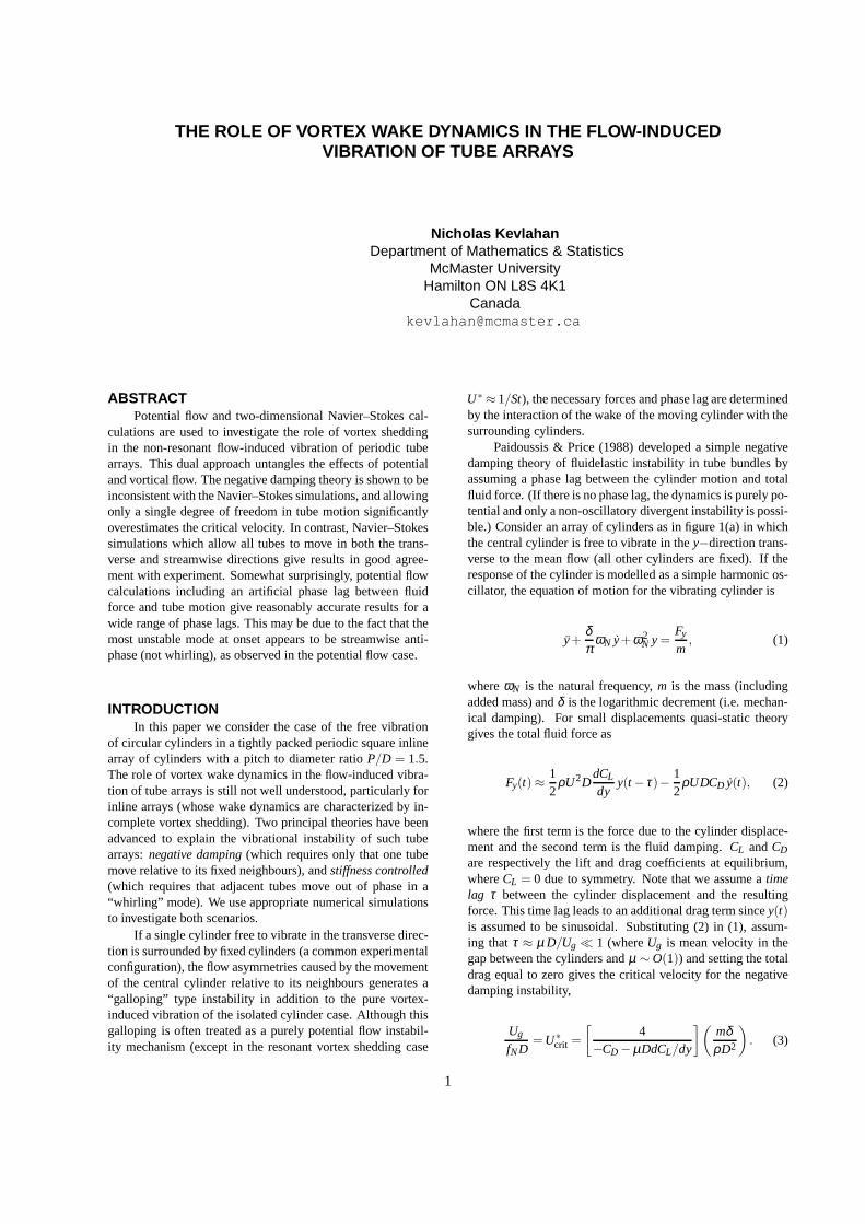
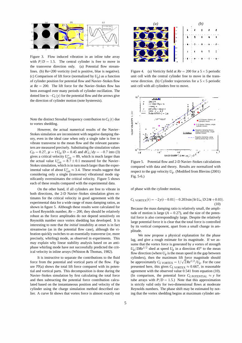
When the central cylinder is free to move in the trans-verse direction, and all other cylinders are fixed, it undergoeslarge periodic oscillations. Figure 3(b) confirms that the vor-tex wake dynamics is strongly modified by the cylinder mo-tion. The wake is stabilized (i.e. it becomes essentially po-tential flow) at the narrow gap side, while the wide gap sideallows for complete vortex shedding. Comparing figures 3(b)and figure 4(a) suggests visually (as confirmed by quantita-tive calculations) that the 3×3 periodic unit cell captures themain vortex wake dynamics. Figure??(a) shows that the vor-tex contribution to the total lift is large: about twice as large inmagnitude as the contribution from the potential flow. How-ever, since the contributions from the vorticity and potentialflow are exactly anti-phase, the maximum amplitude of the to-tal lift force is is similar to that of the potential flow alone. Itis important to remember, however, that the potential forceisproportional to cylinder displacement, and so the vortex forcewill strongly dominate for small amplitude vibrations. Thevortex force is anti-phase with the cylinder motion (and hencethe potential force) because a positive vortex is shed from thelower side of the cylinder when cylinder displacementy(t)is maximum, thus generating a strong downward force. Thefundamental difference between the potential flow and vorti-cal flow is illustrated by figure 3(c), which shows that vortexshedding reverses the sign ofCL(y), breaks monotonicity andintroduces significant hysteresis (CL depends on the velocityof the cylinder as well as its position). In particular, maxi-mum lift force is achieved for intermediate (not maximum)displacements of the cylinder in the vortical flow.
It is interesting to check whether the negative dampingtheory (3) is consistent with the Navier–Stokes simulationre-sults. Curve fitting shows that the cylinder displacement andlift force (normalized by the gap velocityUg = 3U∞) are re-spectively
y(t) = 0.27 sin1.1ωN t,
CL(t) = −0.7y(t −0.03)−0.19 sin(StU∞/D2πt).
These results confirm that, as required for the negative damp-ing instability mechanism (3),dCL/dy = −0.7 < 0 and thereis a phase lag between the fluid force and the cylinder motionof φ = ωτ = π −0.2 (taking into account the change in sign).
4
−0.3 −0.2 −0.1 0 0.1 0.2 0.3−4
−2
0
2
4
y
CL
Pot. flow
Re=200
−1 0 1−1.5
−1
−0.5
0
0.5
1
1.5(a) (b) (c)
Figure 3. Flow induced vibration in an inline tube arraywith P/D = 1.5. The central cylinder is free to move inthe transverse direction only. (a) Potential flow stream-lines. (b) Re=200 vorticity (red is positive, blue is negative).(c) Comparison of lift force (normalized byUg) as a functionof cylinder position for potential flow and Navier–Stokes flowat Re = 200. The lift force for the Navier–Stokes flow hasbeen averaged over many periods of cylinder oscillation. Thedotted line is−CL(y) for the potential flow and the arrows givethe direction of cylinder motion (note hysteresis).
Note the distinct Strouhal frequency contribution toCL(t) dueto vortex shedding.
However, the actual numerical results of the Navier–Stokes simulation are inconsistent with negative damping the-ory, even in the ideal case when only a single tube is free tovibrate transverse to the mean flow and the relevant parame-ters are measured precisely. Substituting the simulation valuesCD = 0.27, µ = τ Ug/D = 0.45 anddCL/dy = −0.7 into (3)gives a critical velocityU∗
crit = 89, which is much larger thanthe actual valueU∗
crit = 8.7± 0.1 measured for the Navier–Stokes simulation, which is in turn much larger than the exper-imental value of aboutU∗
crit ≈ 3.4. These results suggest thatconsidering only a single (transverse) vibrational mode sig-nificantly overestimates the critical velocity. Figure 5 showseach of these results compared with the experimental data.
On the other hand, if all cylinders are free to vibrate inboth directions, the 2-D Navier–Stokes simulation gives es-timates for the critical velocity in good agreement with theexperimental data for a wide range of mass damping ratios, asshown in figure 5. Although these results were calculated fora fixed Reynolds number,Re = 200, they should be relativelyrobust as the force amplitudes do not depend sensitively onReynolds number once vortex shedding has developed. It isinteresting to note that theinitial instability at onset is in factstreamwise (as in the potential flow case), although the vi-bration quickly switches to an essentially transverse (or,moreprecisely, whirling) mode, as observed in experiments. Thismay explain why linear stability analysis based on an anti-phase whirling mode have not successfully predicted the crit-ical velocity in inline arrays (Whiston & Thomas, 1982).
It is instructive to separate the contributions to the fluidforce from the potential and vortical parts of the flow. Fig-ure ??(a) shows the total lift force compared with its poten-tial and vortical parts. This decomposition is done during theNavier–Stokes simulation by first calculating the total forceand then subtracting the potential force contribution calcu-lated based on the instantaneous position and velocity of thecylinder using the charge simulation method described ear-lier. A curve fit shows that vortex force is almost exactly out
(a) (b)
Figure 4. (a) Vorticity field atRe = 200 for a 5×5 periodicunit cell with the central cylinder free to move in the trans-verse direction. (b) Cylinder trajectories for a 5×5 periodicunit cell with all cylinders free to move.
2−D Navier−Stokes, all cylinders move.
2−D Navier−Stokes, singlecylinder moves.
using numerical fits, singleNegative damping theory,
cylinder moves.
Negative damping, usingoptimal phase lag, C=5.2.
Figure 5. Potential flow and 2-D Navier–Stokes calculationscompared with data and theory. Results are normalized withrespect to the gap velocityUg. (Modified from Blevins (2001)Fig. 5-6.)
of phase with the cylinder motion,
CL VORTEX(t)=−2y(t−0.01)−0.203sin(St U∞/D 2πt +0.03).(10)
Because the mass damping ratio is relatively small, the ampli-tude of motion is large (A = 0.27), and the size of the poten-tial force is also correspondingly large. Despite the relativelylarge potential force it is clear that the total force is controlledby its vortical component, apart from a small change in am-plitude.
We now propose a physical explanation for the phaselag, and give a rough estimate for its magnitude. If we as-sume that the vortex force is generated by a vortex of strengthUg/DRe1/2 shed at speedUg in a direction 45o to the meanflow direction (whereUg is the mean speed in the gap betweencylinders), then the maximum lift force magnitude shouldbe approximatelyCL VORTEX = 1/
√2Re1/2/Ug. For the case
presented here, this givesCL VORTEX ≈ 0.667, in reasonableagreement with the observed value 0.541 from equation (10).(In comparison, the potential forceCL POTENTIAL ≈ y fortube arrays withP/D = 1.5.) Note that this approximationis strictly valid only for two-dimensional flows at moderateReynolds numbers. The phase shift may be estimated by not-ing that the vortex shedding begins at maximum cylinder am-
5

plitude (minimum gap). However the vortex initially movesvertically (generating no lift). The lift is maximum whenthe vortex moves below the cylinder into the fast downstreamflow. This givesφvortex ≈ π/8 D/Ug ω ≈ 0.18 in our case,in reasonable agreement with the observed value 0.2 (the 1/8of the circumference estimate was used based on observingflow animations). This estimate agrees with the experimentalobservation thatτ ∝ D/Ug (Blevins, 2001).
3 ConclusionsThe results presented here have helped to untangle the
roles of vortex shedding and potential flow in the non-resonantfluidelastic instability of tube arrays. We have shown that vor-tex wake dynamics (especially vortex shedding) is the domi-nant factor determining the vibrational stability of inline tubearrays, even in the non-resonant case.
In particular, we have shown how flow asymmetry (a po-tential flow effect) ensures that the vortex-generated liftforcedCL/dy < 0, which is necessary for the negative damping in-stability mechanism. The negative damping mechanism alsorequires that the fluid force lag behind the cylinder motionand our results allowed us to measure this phase lag, and tounderstand why it is proportional toD/Ug, as observed exper-imentally. However, we found that the simple negative damp-ing theory is inconsistent with the results of the 2-D Navier–Stokes simulations, even when the relevant parameters mea-sured from the simulation are used to predict the critical flowvelocity. Moreover, we found that the critical flow velocitymeasured in the 2-D Navier–Stokes simulations for a singlecylinder moving transverse to the flow is much higher thanthat measured in experiments. In contrast, nonlinear stabilityanalysis using the 2-D Navier–Stokes simulations of the casewhere all cylinders are free to move in both the streamwiseand transverse directions gave results consistent with theex-periments over a large range of mass damping ratios, from 1to 100.
In order to check that the fully-developed vibrational in-stability is controlled by the vortical part of the total fluid force(and that the potential part does not play a direct role) we per-formed 2-D Navier–Stokes simulations where the cylinder isforced either by the total force, or by the potential force alone,or by the vortical force alone. These numerical experimentsconfirmed that the vibrational instability is due to the vorti-cal part of the force, and that the vortex shedding ensures thatthe force is approximately anti-phase to the cylinder motion(together with a Strouhal frequency component).
Surprisingly, we found that the potential flow simulationsgave reasonably accurate predictions of the critical flow veloc-ity for a wide range of phase lags, provided all cylinders arefree to oscillate in both streamwise and transverse directions.The instability mode in this case is essentially streamwise,with adjacent cylinders moving anti-phase. We conjecture thatthe accuracy of the potential flow calculations is due to thefact that the initial instability mode in the 2-D Navier–Stokessimulations is also streamwise (although the fully-developedinstability mode is the so-called whirling mode, as observedin experiments). This suggests that potential flow calculationsmay be far more accurate than previously thought, provided
the gap velocity is measured correctly and that the cylindersare free to vibrate in the streamwise direction. It also suggeststhat the linear instability analysis of tube arrays should assumea streamwise anti-phase mode, rather than the usual whirling(or transverse) anti-phsase mode.
In summary, we found that 2-D Navier–Stokes simula-tions of periodic arrays of cylinders give good predictionsofthe critical flow velocity for the vibrational instability of inlinetube arrays over a wide range of mass damping ratios. Thefact that the potential flow stability analysis also gives rea-sonably good results for the critical flow velocity is surprisingand requires further analysis, focusing on the form of the ini-tial instability mode. The initial instability mode is likely to bequalitatively different from the fully-developed mode becausethe dynamics of the wake changes qualitatively in inline arraysonce the tubes start to vibrate (from jet-like to von Karman-like with complete vortex shedding).
REFERENCESAmano, K., Okano, D., Ogata, H., Shimohira, H. & Sugi-
hara, M. 2001 A systematic scheme of numerical confor-mal mapping of unbounded multiply-connected domainsby the charge simulation method.Information ProcessingSoc. Japan J. 43 (3), 385–395.
Amaya, Y. & Sakajo, T. 2008 Charge simulation method forapproximating the complex potential in a channel domainwith multiple circular islands. InJST Presto Symposium onMathematical Sciences towards Environmental Problems(Hokkaido University technical report series in mathemat-ics ; 136), pp. 42–45.
Blevins, R.D. 2001Flow-induced vibration, 2nd edn. KriegerPublishing Company.
Connors, H.J. 1978 Fluidelastic vibration of heat exchangertube arrays.J. Mech. Design 100, 347–353.
Edwards, W. S., Tuckerman, L. S., Friesner, R. A. &Sorensen, D. C. 1994 Krylov methods for the incompress-ible Navier–Stokes equations.J. Comp. Phys. 110, 82–102.
Kevlahan, N. K.-R. & Wadsley, J. 2005 Suppression of three-dimensional flow instabilities in tube bundles.J. FluidsStruc. 20 (4), 611–620.
Paidoussis, M.P., Mavriplis, D. & Price, S.J. 1982 A potential-flow theory for the dynamics of cylinder arrays in cross-flow. J. Fluid Mech. 146, 227–252.
Paidoussis, M.P. & Price, S.J. 1988 The mechanisms under-lying flow-induced instabilities of cylinder arrays in cross-flow. J. Fluid Mech. 187, 45–59.
Price, S. J., Paıdoussis, M. P. & Mark, B. 1995 Flow visualiza-tion of the interstitial cross-flow through parallel trangularand rotated square arrays of cylinders.J. Sound and Vibra-tion 181, 85–98.
Vincent, A. & Meneguzzi, M. 1991 The spatial structure andstatistical properties of homogeneous turbulence.J. FluidMech. 225, 1–20.
Whiston, G.S. & Thomas, G.D. 1982 Whirling instabilities inheat exchanger tube arrays.J. Sound Vibration 81 (1).
Williamson, C.H.K. & Govardhan, R. 2004 Vortex-inducedvibration.Ann. Rev. Fluid Mech. 36, 413–455.
6