Embed Size (px)
Citation preview

Journal of Fluids and Structures�����������
000, 000–000doi:??.????/ jfls.2003.0000,available online at http://www.idealibrary.comon
Coupling of structure and wake oscillators in vortex-inducedvibrations
(submitted to the Journal of Fluids and Structures, 05 august 2002, and in revised form, 11 March 2003)
MATTEO LUCA FACCHINETTI and EMMANUEL DE LANGREDepartment of Mechanics - LadHyX, CNRS - Ecole Polytechnique, 91128 Palaiseau, France
FRANCIS BIOLLEYDepartment of Applied Mechanics - Institut Francais du Petrole, 92852 Rueil-Malmaison, France
A class of low-order models for vortex-induced vibrations is analyzed. A classical van der Polequation models the near wake dynamics describing the fluctuating nature of vortex shedding. Thiswake oscillator interacts with the equation of motion of a one degree-of-freedom structure oscillatorand several types of linear coupling terms modeling the fluid-structure interaction are considered.The model dynamics is investigated analytically and discussed with respect to the choice of thecoupling terms and the values of model parameters. Closed form relations of the model responseare derived and compared to experimental results on forced and free vortex-induced vibrations. Thisallows us to set the values of all model parameters, then leads to the choice of the most adequatecoupling model. A linear inertial action of the structure on the fluid is thus found to describe most ofthe features of vortex-induced vibration phenomenology, such as Griffin plots and lock-in domains.
c
2003 Academic Press
1. INTRODUCTION
VORTEX-INDUCED VIBRATIONS (VIV) are a well-known phenomenon to engineers. Severalkinds of structures subjected to wind or water currents may experience VIV: common posts, chim-neys, suspended cables for bridges, power transmission lines in air, and pipes, risers, towing cables,mooring lines in water. In some cases, this has to be taken into account in their design as a potentialcause of fatigue damage, such as for offshore structures.
Nominal two-dimensional (2-D) vortex shedding and consecutive VIV have been considered inearlier studies as the simplest form of the problem. Focusing onto crosswise VIV, phenomenolog-ical models have been developed in the 1970s following the idea of a wake oscillator [1, 2]. Thenear wake dynamics was described by a single flow variable modeling the fluctuating nature of thevortex shedding. This variable was assumed to satisfy a van der Pol or Rayleigh equation whichmodels a self-sustained, stable and nearly harmonic oscillation of finite amplitude. This elemen-tary wake oscillator was naturally coupled with the motion equation of a one degree-of-freedom(1DOF) elastically supported rigid structure, namely a structure oscillator. Some major features ofthe near wake vortex-shedding and VIV have been thus qualitatively and quantitatively described,using analytical and numerical methods. For a comprehensive review see for instance [3].
Increasing computational resources have made possible the direct numerical simulation (DNS)
0889–9746/99/100813 + 39 $30.00/0 c
2003 Academic Press

VIV AND WAKE OSCILLATORS 2
of incompressible Navier-Stokes equations on 2-D domains around a fixed, forced or free structureprofile: this has provided more detailed flow field analysis to compare with experimental observa-tions.
Three-dimensional (3-D) features naturally arise in the VIV problem as the real domain is ex-plicitly considered as spanwise extended: elastic structures like tensioned cables and beams arecharacterized by their eigenmodes, wake flows show secondary instabilities and the environmentmay impose shear flow. From a numerical point of view, computational limits arise for flow-fielddirect numerical simulation capability in modeling 3-D domains with large aspect ratio: simulationsof VIV on flexible tensioned cables and beams have been performed for Reynolds number ��� up to� ���
and aspect ratio of about� ���
[4].Phenomenological models based on wake oscillators may again be useful in describing such
problems. Allowing accessible analytical considerations, they help in the understanding of theunderlying physics. This explains several recent improvements in this approach. The original kernelin the form of van der Pol or Rayleigh equation has been re-interpreted by Skop & al. [5,6], Krenk &al. [7], Mureithi & al. [8] and Plaschko [9], and then applied in its 3-D version. Wake oscillators havebeen continuously distributed along the spanwise extent of a slender structure and allowed to interactdirectly, in order to describe 3-D features of vortex shedding from stationary structures [10,11] andVIV of slender structures in uniform and shear flows [12–15]. Moreover, other low-order modelshave also been proposed in the literature for the 3-D wake dynamics behind stationary or vibrating(forced) slender structures, such as non-linear circle map oscillators [16] and the complex Ginzburg-Landau equation [17–19].
Considering this large variety there is definitely a need to have a critical analysis in terms ofthe fundamental behavior associated with the simplest forms of the model. In the present papera class of low-order models for transverse VIV of 1DOF structures in stationary uniform flow isinvestigated. The basic van der Pol kernel is selected as a generic model (section 2). In order tokeep the model as simple as possible, only linear coupling terms for the fluid-structure interactionsare considered. The model dynamics is investigated analytically and discussed with respect to thetype of coupling and the value of its parameters. This allows us to compare the basic dynamics of oldcoupling models of the literature with the proposed new one, which considers a linear inertial actionof the structure on the near wake. The constant values of all model parameters are first estimatedfrom experimental data considering a forced wake oscillator, modeling the vortex shedding behinda structure whose movement is imposed (section 3). The dynamical properties associated with thedifferent coupling models are expressed in closed form and then compared for both forced and fullycoupled wake and structure oscillators (section 4). While the qualitative dynamics of the couplingmodels proposed by other authors is recovered from these solutions, a new linear inertial couplingis shown to be the most effective in describing, qualitatively and in some aspects quantitatively,the main features of 2-D VIV phenomenology. Discussion and conclusions are finally developed(sections 5 and 6).
2. VIV MODEL
2.1. STRUCTURE OSCILLATOR
Let us consider a one degree-of-freedom (1DOF) elastically supported rigid circular cylinder ofdiameter � , constrained to oscillate transversely to a stationary and uniform flow of free stream ve-locity � , figure 1. The dimensional in-plane cross-flow displacement of the structure is describedby the linear oscillator

VIV AND WAKE OSCILLATORS 3
PSfrag replacements
���
�
�
� ��
� ��� �
Figure 1. Model of coupled structure and wake oscillators for 2-D vortex-induced vibrations.
��� �� �� � ���� � (1)
referred to as the structure oscillator in the sequel, where� � means derivative with respect to the
dimensional time � . The mass � takes into account both the mass of the structure ��� and the fluidadded mass ��� , which models inviscid inertial effects [20], and reads� � ��� � ��� � ��� ������� �! #"%$'& �)(*� � ��� � ��� � $+� �, -� (2)
where the fluid density is � , ( is a dimensionless mass ratio and �.� is the added mass coefficient.In equation (1) the linear damping � models both viscous dissipations in the support �/� and the fluidadded damping �0� [20], namely� � �1� � �1� � �1� �32546� �, 7� (3)
where 2 is a stall parameter (see [5, 6]) and 4 a reference angular frequency. In still fluid 4 is theangular frequency of the structure motion and 2 is a function of the oscillation amplitude, relatedto the mean sectional drag coefficient of the structure �98 [20]. In our case of cross-flow 4 isthe vortex-shedding angular frequency, 4:�;4 � � � "<�>= �.$ � , where �>= is the Strouhal number,and 2 is again related to �#8 [20]. For the sake of simplicity 2 is here assumed to be a constant.This is equivalent to the model proposed by Skop & al. [5, 6]. In equation (1) the stiffness
�only
relates to external effects. In order to develop a 2D model for VIV, all mass, damping and stiffnessparameters are defined per unit length. Following Williamson & al. [21], hydrodynamic actionson the structure are here decomposed in two parts: the basic fluid effects, � � and � � , are directlyincluded in the structure oscillator through � and � , equations (2) and (3), while the effects ofvortices are modeled by the right-hand side forcing term � , to be discussed later. Defining thestructural angular frequency 4 � � � � $ � �@?BA C
and the structure reduced damping DE� � � $ � � � 4 � � ,equation (1) becomes �� F � D/4 � � 2( 4 �HGI ��J4 � ���<$ � K (4)

VIV AND WAKE OSCILLATORS 4
2.2. WAKE OSCILLATOR
The fluctuating nature of the vortex street is modeled by a non-linear oscillator satisfying the vander Pol equation [22] � ���/4 ��� � �� ��� � � 4# � � �� � (5)
referred to as the wake oscillator in the sequel. The dimensionless wake variable � , figure 1, maybe associated to the fluctuating lift coefficient on the structure, as for most of the models in theliterature since the pioneering work of Hartlen & al. [23]. It may alternatively be considered as ahidden flow variable related to a weighted average of the transverse component of the flow [20], orassumed to be proportional to the transverse velocity of a representative near wake fluid mass [7]. Ithas also been associated to the mean transverse displacement of the local near wake fluid layer withrespect to the mean streamwise axis [10]. The right-hand side forcing term � models the effects ofthe cylinder motion on the near wake. When � � �
and�� � � �
, the wake oscillator (5) is knownto provide a stable quasi-harmonic oscillation of finite amplitude ��� � �
at the angular frequency4 � [22]. Note here that considering a viscous term in the form �/4 ��� � � � � � , then referring to aRayleigh equation as first proposed by [23], or a combination of both van der Pol and Rayleigh forms�/4 � � � � � � � � � as considered by Krenk & al. [7], does not affect the capability of modelinga self-sustained stable quasi-harmonic oscillation of finite amplitude at the angular frequency 4 � ,namely a limit cycle in the phase portrait.
2.3. COUPLING OF WAKE AND STRUCTURE OSCILLATORS
Introducing the dimensionless time� � � 4 � and space coordinate � � #$ � , equations (4) and
(5) lead to the coupled fluid-structure dynamical system
� � F � D��9� 2( G � ���0 � ��� � � ��� � � �� ��� � � � ��� � (6)
where ��� 4 � $H4 � is the reduced angular frequency of the structure, also related to the reduced flowvelocity ��� by
� � 4 �� "<�>= � �+$ � � � �
�>= ��� � � � � � "4 � �� � (7)
and the dimensionless coupling terms read
� � ��E4 � � ��� �&/" � = � � ����� �
�!4 � ��� �& " � = � K (8)
Over-dots now mean derivative with respect to the dimensionless time�. System (6) is the basic
form of phenomenological models of VIV using van der Pol oscillators, as considered in this paper.Several ideas have been proposed since Hartlen & al. [23], in order to model the fluid-structure cou-pling terms on the right-hand side. Adding non-linearities on the left-hand side was also explored,as an attempt to match the model dynamical behavior with experimental results. For the most recentdevelopments, see [5–9].
In order to keep the model as simple as possible, the fluid-structure coupling terms on the right-hand side are here limited to be linear functions of � and � and their time derivatives. No othernon-linearity is added in the system (6), so that the only one is that of the van der Pol wake oscillator.
Since [23], the action � of the fluid near wake on the structure is usually considered as a fluctuatinglift force. In dimensional variables, it reads
� � �� � � ����� K (9)

VIV AND WAKE OSCILLATORS 5
Note here that ��� does not correspond to the total instantaneous sectional lift coefficient on thestructure because of � represents the forcing caused only by vorticity in the wake. Following [21],in the sequel we will refer to � � as a vortex lift coefficient and to � = � =� as the total lift coefficient.The fluid variable � is then interpreted as a reduced vortex lift coefficient � � � ���<$/��� � , where thereference lift coefficient � � � is that observed on a fixed structure subjected to vortex shedding. Theratio
� � � $ � �:���<$/� � � therefore describes the vortex lift magnification with respect to a fixedstructure experiencing vortex shedding. In dimensionless form the action (9) reads
� ��� � ���)� ��� �� �� " � = ( K (10)
Since ( is a mass ratio, equation (2), � is essentially a mass number and scales the effect of thewake on the structure.
Conversely, several choices may be considered for the action � of the structure on the fluid wakeoscillator. Hartlen & al. [23] have first taken “rather arbitrarily” (as stated in their original paper)a velocity coupling � ��� � , � being a parameter, as later assumed in [24, 25] and more recentlyin [8, 9]. Krenk & al. [7] have suggested another model based on energy considerations: enforcinga direct flow of energy from the wake oscillator to the structure, in the formulation (6) they deriveda displacement coupling � ��� � . As a third choice, we propose here a linear inertial effect ofthe structure on the fluid, namely an acceleration coupling ��� � . The latter coupling hasbeen previously considered in the literature, but only in combined models of VIV and galloping,see [3, 20].
3. VALUES OF MODEL PARAMETERS
In this section all parameters of the class of models presented above are estimated through experi-mental data on free and forced vortex shedding behind cylinders. In order to compare the dynamicalbehavior of the three coupling models on a common basis, model parameters are fixed to the sameconstant values for the three coupling models.
In the dynamics of the structure oscillator, equation (6), the reduced damping D is a given pa-rameter. The reduced frequency � , equation (7), is also a given parameter that depends only on theStrouhal number � = and the reduced velocity ��� . It is common practice to assume � = � � K � in thesub-critical range,
����� � � � K� � � � C [20, 26]. Similarly, the mass ratio ( is directly derived
from the structure and fluid masses, equation (2), assuming a constant added mass coefficient � �derived from potential flow theory [20]: in the case of a circular cross section it reads �.� � �
. Themass number � is then derived by equation (10). The reference lift coefficient � � � being usuallytaken as � � � � � K � in a large range of � � [20, 26], using (10) we have therefore
�)� � K � $'( K (11)
The only remaining parameter to be determined in the equation of the structure oscillator is the fluidadded damping coefficient 2 , which is directly related to the mean sectional drag coefficient of thestructure through [20] 25� � 8&/"<� = K (12)
For stationary cylinders in the sub-critical range,�����
� � � K��� � � C , we assume � 8 � � � K � [26].
A drag magnification depending on the structure transverse motion may be taken into account in theform
� � � � � � � ��8 � [20, 26], yielding a non-linear term in the structure oscillator, but for the sake

VIV AND WAKE OSCILLATORS 6
of simplicity we assume here a constant amplified drag coefficient � 8 � � K � , so that from equation(12) 25� � K � K (13)
For the wake oscillator dynamics, equation (6), we only need to set values of the van der Polparameter � and the scaling of the coupling force � , namely � . This is done here by analyzingthe effects of an imposed motion of the structure on the near wake dynamics. Experiments sincethose of Bishop & al. [2] show that the lift force acting on the structure, namely � , is magnifiedby an imposed structure motion � , particularly at resonance. When the frequency of the forcingis close to the natural vortex shedding frequency, the vortex street deviates from Strouhal’s lawand synchronizes onto the forcing frequency, defining a lock-in state. Moreover, the phase showsan overall jump of about " when passing through lock-in, � and � being in-phase at low � � andout-of-phase at high � � , as confirmed by recent investigations on vortex shedding timing [27, 28].
Considering an harmonic motion of dimensionless amplitude � � and angular frequency � , namely� � � ������� � � � � , the wake oscillator in (6) is forced by � which reads depending on the couplingmodel
�5� � � � ����� � � � � ����� � ��� � � ��� � � � � ���E� � � � � � ����� � � � � � (14)
in the case of displacement, velocity and acceleration coupling, respectively. Defining a reducedvelocity based on the forcing frequency as
� �+� � "� 4 � �� � ��6� = � (15)
the response of the wake oscillator is now analyzed for the three models of coupling in the param-eter space
����0� � � � . Enforcing the hypothesis of harmonicity and frequency synchronization, the
response is sought in the form � � ��� ����� � � � ��� � , where � � and � are time-independent amplitudeand phase, respectively. Substituting in the wake oscillator, equation (6), and considering only themain harmonic contribution of the non-linearities, elementary algebra yields the amplitude of thetransfer function of the wake oscillator���� � � ���� � ����� � � F � � �
��� G �� � � � ��� F�� � ���� G � (16)
where� � � is the amplitude of the forcing. Defining a reference lock-in state by �6� �
at � � � � $/� = ,equation (15), the vortex lift magnification factor with respect to a stationary structure experiencingvortex shedding,
� � � � $ � , is derived as the unique real root of the bi-cubic polynomial of � � ,equation (16), and reads
� � F��� � G �! � F &� � G �! with� � F#" � � � �BG �%$ F#" � � � � G ��& � K (17)
In the literature, forced oscillation results are usually presented in terms of the total lift coefficient� = � =� , which is related to the vortex lift coefficient � � by the added mass effect� = � =� ��� � � �#� � " � � = � � (18)
so that for a harmonic evolution the total lift magnification factor� = � = reads
� = � = �&$ F � ����� ��� ������ � � " �� � � � G �(' � �)� �+* K (19)
The particular choice of the coupling model does not affect the value of�
because at the referenceunitary angular frequency � � �
, so that in all cases we have� � � � � � � . Conversely, the relation
VIV AND WAKE OSCILLATORS 7
between� = � = and
�does depend on the phase � , and thus on the particular coupling model, as it
will be discussed in the next section. In order to set the value of the parameters � and � once for allfor the three coupling models, the approximation � = � =� � ��� is here applied. This implies a shiftfor the values of the parameters, but does not modify the basic dynamical behavior of the models:the comparison between them is thus made easier on a common basis. A further discussion on thevalue of � and � is provided in section 5.
Under this approximation, the value of the combined parameter � $�� is first derived by match-ing the model response (17) to experimental data on total lift magnification from the literature[2, 26, 29–31]. The value of � $�� � & � is proposed from a least square interpolation, figure 2.Note that at higher imposed structure motion amplitudes, � ��� � K� , experiments show that the liftmagnification
�becomes a decreasing function of � � [2,26,29–31]. This occurs when � � becomes
too large with respect to the natural crosswise spacing of the near wake vortex street, as discussedin [32]. This feature may not be explicitly described by a van der Pol wake oscillator forced by thestructure motion, as the amplitude of its stable limit cycle grows indefinitely as a function of theforcing amplitude. Note also that
�might depend on other parameters than the structure oscillation
amplitude and frequency, but this is not considered in our approach.
0 0.1 0.2 0.3 0.4 0.5 0.61
1.5
2
2.5
3
PSfrag replacements
�
� �Figure 2. Lift magnification � as a function of the imposed structure motion amplitude ��� . The model response(17) is fitted to experimental data: � , [29]; x, [2]; *, [30]; , [31]; , [26]. Model parameters: ��� � , ����������� ;—, ����������� (proposed value); - -, ����������� .
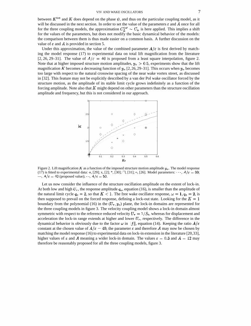
Let us now consider the influence of the structure oscillation amplitude on the extent of lock-in.At both low and high ��� , the response amplitude ��� , equation (16), is smaller than the amplitude ofthe natural limit cycle � � � �
, so that� �
. The free wake oscillator response, � � � � ��� � �, is
then supposed to prevail on the forced response, defining a lock-out state. Looking for the� � �
boundary from the polynomial (16) in the ( � �0� � � ) plane, the lock-in domains are represented forthe three coupling models in figure 3. The velocity coupling model shows a lock-in domain almostsymmetric with respect to the reference reduced velocity � �.� � $/�>= , whereas for displacement andacceleration the lock-in range extends at higher and lower � � , respectively. The difference in thedynamical behavior is obviously due to the factor � in
� � � , equation (14). Keeping the ratio � $ �constant at the chosen value of � $�� ��& � , the parameter � and therefore � may now be chosen bymatching the model response (16) to experimental data on lock-in extension in the literature [20,33],higher values of � and � meaning a wider lock-in domain. The values �E� � K � and ��� � �
maytherefore be reasonably proposed for all the three coupling models, figure 3.
VIV AND WAKE OSCILLATORS 8
0 2 4 6 8 100
0.1
0.2
0.3
0.4
0.5
PSfrag replacements
� �
���
(a)
0 2 4 6 8 100
0.1
0.2
0.3
0.4
0.5
PSfrag replacements
� �
���
(b)
0 2 4 6 8 100
0.1
0.2
0.3
0.4
0.5
PSfrag replacements
� �
���
(c)
Figure 3. Lock-in domain in the (����� ��� ) plane looking for � �� boundary in the polynomial (16) for the
different coupling models: (a) displacement, (b) velocity, (c) acceleration. Experimental data: ��� , [20, 33].Model parameters: � � � , ��� �� � ; —, ��� �� � (proposed value); - -, ������ � .

VIV AND WAKE OSCILLATORS 9
4. DYNAMICAL BEHAVIOR OF THE COUPLED MODEL
In this section the dynamical behavior of the coupled system is analyzed and its solutions areinvestigated in the scope of differentiating the influence of the choice of the coupling model. Forthe displacement and velocity couplings, some of the dynamics have been described in [7] and [5],respectively. The parameters � � 2 � � � � are fixed now at the values obtained in the previous section,namely � � � K � $1( � 2,� � K � � � � � K � � ��� � �
.
4.1. FORCED WAKE OSCILLATOR
Let us first come back to the case of an imposed motion of the structure on the near wake dynam-ics, i.e. to forced vortex shedding as in the preceding section. The phase of the transfer function ofthe wake oscillator may be analytically derived as for its amplitude counterpart (16) and reads�J��� � �J��� � " � � �J��� � " with ��� � � � ���� � �
F � �& � � G � (20)
for the displacement, velocity and acceleration coupling models, respectively. In figure 4 it appearsthat the acceleration model seems more effective in describing the phase between the imposed struc-ture motion and the fluctuating lift as observed in experiments [2, 28, 34]: � and � are found to bein-phase at low ��� and out-of-phase at high � � .
0 1 2 3 4 5 6 7 8 9 10−1
−0.5
0
0.5
1PSfrag replacements
� �
��
Figure 4. Phase of � with respect to � as a function of� �
, equation (20), for the different coupling models:� � � , displacement; - -, velocity; — acceleration. Experimental data: *, [2]; x, [28]; , [34].
4.2. COUPLED SYSTEM
Let us now consider the coupled fluid-structure system given by (6). To the leading order, asolution is sought in the form� � � � � � � ����� � � � � � � � � � � � � ����� � � � � � � � (21)
where the structure and fluid signals admit time-independent common angular frequency � , am-plitudes � � � � � and relative phase � . Substitution in the structure oscillator equation yields the

VIV AND WAKE OSCILLATORS 10
amplitude and phase of the linear transfer function between the structure displacement and the fluidvariable� �� � � ��� � �0 �� � � �� ��� D��9� 2<$1( � � ���� ?BA C � � � � � � � � � D��#� 2 $'( � �
� � � K (22)
Substituting now in the wake oscillator equation and considering only the main harmonic contribu-tion of the non-linearities, elementary algebra finally yields two equations on the amplitude � � andthe angular frequency �
� � � ��� � � � �� �� � � � � � ��� D��+� 2<$1( � � � ? A C � (23)� � � � � � � �0 � � � D��+� 2<$1( � � � � � � � � �0 � ��� D��9� 2<$1( � � � � � � ��� � ���� � � (24)
where the coefficients � and depend on the particular coupling model � . For the displacementcoupling it reads ��� � ��� D��9� 2<$1( � ��:��� � � �0 �� � � � (25)
for the velocity coupling � ���0 � � 7�� � � � ��� D��+� 2<$1( � � � (26)
and for the acceleration coupling��� ��� D��+� 2<$1( � � �� � � � � � �� �0 � � K (27)
The angular frequency � directly arises as a solution of the bi-cubic equations (24), yielding oneor three positive real roots. The amplitudes � � � � � and the relative phase � then derive accordingly,via (23) and (22), respectively. Distinct roots are associated to hysteretic behavior. We may nowexplore these various solutions depending on the particular choice of the coupling models, when thereduced velocity is varied. In order to illustrate this, we shall consider the case of a uniform pivotedcylinder experiencing transverse VIV in uniform flow [12], for which D�� � K � � � � � � � � � � � � � � � .In order to assess the stability of all solutions, the dynamical system (6) has been numerically treatedby standard centered finite difference in time and integrated by a second order accurate time explicitscheme.
Let us first consider the appearance of the lock-in phenomenon which we define here as a de-viation of the wake and structure common frequency � from Strouhal law, namely � � �
. Forall the three models of coupling, the system angular frequency resulting from (24) is found to belocked onto the structure angular frequency � � �6� � $ � � = � � � around � � � � $H�>= , figure 5.Actually, the basic resonance state � � � � � for which � �!� � $/�>= is not an exact solution forthe velocity coupling, as it is for displacement and acceleration models. Out of lock-in, the coupledsystem is synchronized onto the vortex shedding angular frequency �6� �
. For the acceleration cou-pling, hysteretic behavior occurs at both lock-in boundaries, whereas for displacement and velocitymodels the whole lock-in domain is characterized by hysteresis. Moreover, for displacement andacceleration couplings, lock-in is nearly symmetric with respect to a reference resonance slightlyhigher than ��� � � $/�>= . Conversely, the dynamical response of the velocity model is asymmetric:the unique lock-in branch develops only at reduced velocities higher than � � � � $/� = , while at lowerreduced velocities there exist only lock-out states.
Let us now consider the amplitude � � of the structure motion, derived from the frequency so-lutions � using equations (23) and (22), figure 6. For all the three coupling models, the lock-incondition is found to yield a magnification of the structure motion, whereas at lock-out the struc-ture is almost at rest, � � � �
. The displacement coupling model displays a very weak motion

VIV AND WAKE OSCILLATORS 11
0.8
1
1.2
0.8
1
1.2
3.5 4 4.5 5 5.5 6 6.5
0.8
1
1.2PSfrag replacements
���
�
�
�
(a)
(b)
(c)
Figure 5. Angular frequency � as a function of reduced velocity� �
: (a) displacement model, (b) velocitymodel, (c) acceleration model. —, increasing
� �; - -, decreasing
���.
amplitude even at lock-in, at least of an order of magnitude less than those of velocity and accelera-tion coupling models. Moreover, the displacement coupling model shows two independent lock-inbranches, as may also be seen in [7], which are not a simple prolongation of a common resonancekernel around � � � � $/� = , as it is for velocity and accelerations couplings.
Considering now the wake variable amplitude � � , figure 7, the displacement coupling modeldoes not succeed in describing the lift magnification during lock-in. In fact, as noted in [7], thiscoupled system is adiabatic: an increase of the structure oscillation amplitude is allowed only by adecrease in the wake oscillation amplitude. Conversely, for velocity and acceleration couplings, alift magnification is observed. Out of lock-in, the system (6) simply models vortex shedding froma stationary structure: the wake oscillator sets itself on the limit cycle of amplitude ��� � �
, thestructure being almost at rest, � � � �
, see figure 6.For all the three coupling models the phase � between the structure and wake oscillators, equation
(22), shows an overall phase jump of " passing through lock-in, figure 8. This is qualitativelyconsistent with results in the literature concerning the change in vortex shedding timing that occurswhen passing through the lock-in domain [21, 28, 35]. Actually, the jump in the lift phase observedin experiments is very abrupt, for both forced and freely vibrating structure. This later feature isnot well represented by the acceleration coupling model, which shows a phase jump at both lock-inboundaries.
Considering the results of figures 5, 6, 7 and 8 on the dynamics of the coupled system (6) when

VIV AND WAKE OSCILLATORS 12
0
0.05
0.1
0
0.05
0.1
3.5 4 4.5 5 5.5 6 6.50
0.05
0.1
PSfrag replacements
� �
� �
� �
� �
(a)
(b)
(c)
Figure 6. Amplitude of the structure oscillator ��� as a function of reduced velocity���
: (a) displacement model,(b) velocity model, (c) acceleration model. —, increasing
� �; - -, decreasing
� �.
��� is varied, we may now say that the displacement coupling model fails in describing two majorfeatures of lock-in, namely large structure oscillations and lift magnification, whereas the velocityand acceleration coupling models yield results that differ between them, namely concerning thelocation of the lock-in domain, but are both qualitatively consistent with experimental data.
4.3. OSCILLATION AMPLITUDE AT LOCK-IN
The maximum structure displacement amplitude at lock-in is typically expressed in the literatureas a function of a single combined mass-damping parameter, namely the Skop-Griffin parameter ���
� � � � " � = (�D � ��� �� D� � (28)
yielding the so-called Griffin plot [35]. Let us now derive an explicit relation between the maximumstructure displacement amplitude and ��� for the coupled system (6), to be compared to experimentaldata.
For the displacement coupling model, the reference resonance state defined by �;� � � �at
� � � � $/� = satisfies the polynomial (24) but it is not exactly associated to the maximum structuredisplacement amplitude, see figure 6a. Nevertheless, this provides a qualitative information on thesystem dynamical behavior at lock-in. Combining equations (22), (23) and (28) yields the structuredisplacement amplitude at � ��� � �

VIV AND WAKE OSCILLATORS 13
1
2
3
1
2
3
3.5 4 4.5 5 5.5 6 6.51
2
3
PSfrag replacements
� �
� �
� �
� �
(a)
(b)
(c)
Figure 7. Amplitude of the wake oscillator � � as a function of reduced velocity� �
: (a) displacement model,(b) velocity model, (c) acceleration model. —, increasing
� �; - -, decreasing
���.
� � � ��� � $ �� � �6&/" � = 2 $ � � � ���� � $'&� � �6&/" � = 2 K (29)
The lift magnification factor with respect to the case of vortex shedding from a stationary structure� � � � ��$ � , correspondingly reads
� � � $ � � � ���� � $'&� �*�6&/" � = 2 K (30)
As observed previously in this section, the displacement model does not succeed in describing thelift magnification during lock-in, see also figure 7a. The lift magnification factor
� � is alwayssmaller than one and is even not defined when ��� is smaller than the critical value
� � � � � � � � � � �& � &/" � = 2�� � K�� K (31)
Equations (29) and (30) provide real positive amplitudes � � and� � for � � � � � � � � only. For
smaller values of � � , the reference resonance state � ����� �is not allowed and the basic resonance
between structure and wake oscillators is suppressed. In this case, the system (6) simply modelsvortex shedding as from a stationary structure: the wake oscillator sets itself on the limit cycle ofamplitude � � � �
and frequency � � �, as in the absence of any forcing, and the structure is almost
at rest, � � � �. In terms of Griffin plot, figure 9, the displacement coupling model clearly fails to
qualitatively match experimental data.

VIV AND WAKE OSCILLATORS 14
−1
−0.5
0
−1
−0.5
0
3.5 4 4.5 5 5.5 6 6.5−1
−0.5
0
PSfrag replacements
� �
��
��
��(a)
(b)
(c)
Figure 8. Phase � between structure and wake oscillators as a function of reduced velocity� �
: (a) displacementmodel, (b) velocity model, (c) acceleration model. —, increasing
� �; - -, decreasing
���.
For the velocity coupling model, the maximum structural displacement amplitude is located al-most at the upper � � boundary of the lock-in domain, which corresponds to the exact solution� ���1���� �
, see figure 5b. Solving (24) under this condition yields
� ��� �� � � &/" 1� = 2 � �0 � � � ��� � � F &/" � = 2 � � ��� �& G � � K (32)
The corresponding structure oscillation amplitude � � and the lift magnification factor� � arise
from (22) and (23) as
� � � � � � � � ����� �� � � ���1��6&/" � = 2 � � � K (33)
The Griffin plot derived from the velocity coupling model, figure 9, is found to underestimate thestructure oscillation amplitude, when using the values of parameters proposed in the precedingsection. Yet, the qualitative influence of the Skop-Griffin parameter is recovered. Particularly, theasymptotic self-limited response amplitude at low � � is assured by the fluid damping 2 .
For the acceleration coupling model a reference resonance state is defined by � � � � �at
� � � � $/� = . It satisfies the frequency equation (24) and yields almost the maximum structuredisplacement amplitude, as previously shown in figure 6c, even if the maximum occurs at a value of� � slightly higher than
� $/� = . Combining equations (22), (23) and (28), the structure displacementamplitude at �6�� � �
reads

VIV AND WAKE OSCILLATORS 15� � � � � � $ �� � �6&/" � = 2 $ � � � � � � � $'&� � �6&/" � = 2 K (34)
The lift magnification factor� � correspondingly reads
� � � $ � � � � � � � $'&� � �6&/" � = 2 K (35)
In terms of Griffin plot, figure 9, this yields results similar to the velocity coupling model.We may therefore state that, as in the preceding section, the displacement coupling model fails in
describing even qualitatively the trend of experimental data of the Griffin plots, whereas the velocityand acceleration coupling models yield similar results, qualitatively consistent with experiments.
10−2
10−1
100
101
10−3
10−2
10−1
100
101
PSfrag replacements
� �
� �
Figure 9. Structural oscillation amplitude at lock-in ��� as a function of the Skop-Griffin parameter ��� : � � � ,displacement model; - -, velocity model; —, acceleration model. Experimental data in air: , [5]. Experimentaldata in water: � , [5]; � , [35].
4.4. EXTENSION OF LOCK-IN
Although the maximum structure displacement � � and the corresponding lift magnification fac-tor� � at lock-in are determined by the single combined mass-damping parameter � � , as verified
for the three coupling models in the previous section, the range of lock-in is known to be a functionof both � � ( � and D separately [21]. At low values of the mass-damping parameter, � � � � K � � ,the model dynamical behavior is now discussed in terms of the recent investigations of Williamson& al. [21, 35]. Another analysis on particular limits in the case of vanishing stiffness may be foundin [36, 37].
The lock-in domain is here considered at a constant � � value as a function of the mass ratio� � ( � only, which is rewritten for the sake of comparison with the literature as��� � &" ( � �#� �
� K �" � � �#� K (36)
Experiments show the existence of a critical mass ratio � �� � � K & , under which large structureoscillation persists for high reduced velocities, at least to the limits of experimental facilities, andthe oscillation frequency increases indefinitely with the flow velocity, meaning unbounded lock-indomain at higher � � .

VIV AND WAKE OSCILLATORS 16
0 2 4 6 8 10 120
5
10
15
20
25
30
PSfrag replacements
���
���
(a)
0 2 4 6 8 10 120
5
10
15
20
25
30
PSfrag replacements
���
� �
(b)
0 2 4 6 8 10 120
5
10
15
20
25
30
PSfrag replacements
���
���
(c)
Figure 10. Lock-in domains as a function of the mass ratio ��� at low � � � �� ��� : (a) displacement model;(b) velocity model; (c) acceleration model. Experimental data from [21]: , lower lock-in bound; , upperlock-in bound.

VIV AND WAKE OSCILLATORS 17
Let us define the range of lock-in, at given values of � � and � � , by an oscillation amplitudethreshold, namely � � � � � � �� � $ � , where the maximum amplitude � � is given in the precedingsection. For the displacement coupling model, the lock-in state is simply defined by � � � � K � & , as� � is not defined for low � � values. The extension of the lock-in domain as a function of � � and � �is derived and plotted in figure 10 for the three coupling models, respectively. For the displacementcoupling model, figure 10a, as � � tends to zero a constant structure oscillation amplitude persists athigh � � . Note that amplitudes are not really of significant magnitude and as � � � � � � � , equation(31), no real positive oscillation amplitudes are allowed around � � � � $H� = . The velocity couplingmodel, figure 10b shows a lock-in domain that enlarges only to a finite reduced velocity range, as� � tends to zero. Conversely, for the acceleration coupling model, figure 10c, as � � tends to zerothe widening of the lock-in domain is clearly unbounded and significant structure oscillations persistat high � � . This latter result is quite consistent with experimental data of [21].
It appears that, in terms of extension of lock-in, the three models yield quite different results,particularly at low mass ratio. In this range, only the acceleration coupling model is able to describethe phenomenon of persistent lock-in. This is illustrated in figure 11a by plotting the structuraloscillation amplitude � � as a function of the reduced velocity � � , at a value of � � � � K � lowerthan the critical mass ratio � �� � � K & found by [21].
(a) (b)
0 5 10 15 20 250
0.2
0.4
0.6
0.8
1
1.2
PSfrag replacements
� �
� �
0 5 10 15 20 250
1
2
3
4
5
PSfrag replacements
� �
� �
Figure 11. Response at low mass ratio � � � �� ��� and low reduced damping� � �� ������� . (a) Oscillation
amplitude. (b) Angular frequency. Experimental data: � , [21]. Present coupled models: � � � , displacement; - -,velocity; —, acceleration.
For the displacement coupling model, a lock-out zone exists around ��� � � $/�>= as we have here� � � � � � � : this is clearly inconsistent with experiments. For the velocity coupling model, asobserved by [23], the computed response sharply decreases after the maximum is reached. Only theacceleration coupling model is found to follow the trend of experiments. This is further confirmedby the evolution of frequency in figure 11b, where the results of the acceleration coupling modelare consistent with experimental data. For the sake of comparison, the dimensionless frequency� � � ��$�� is considered in this figure.
We may therefore state that only the acceleration coupling model is able to describe at leastqualitatively the main features of VIV at low Skop-Griffin parameter � � and mass ratio � � .

VIV AND WAKE OSCILLATORS 18
4.5. EFFECTIVE ADDED MASS
A consideration valid for all the three coupling models may finally be drawn, concerning theeffective added mass exerted on the structure oscillator. In figure 8 the phase � between the structuredisplacement � and the lift � is observed to jump of " passing through the lock-in domain. Thisqualitatively models the changes of vortex timing, lift force phase and then the sign of the lift forcein phase with the structure acceleration, referred to as an effective added mass in the literature [35].All this has already been observed experimentally for forced [28] and free vibrations [21], and alsosimulated by 2-D CFD [27,38]. As described in section 3, at low � � vortices are shed at the structurepeak displacement on the external side and the fluctuating lift force is in-phase with respect to thestructure displacement, leading to a positive effective added mass. Conversely, at high � � vorticesare shed at the structure peak displacement on the internal side and � , � are then out-of-phase,leading to a negative effective added mass. In the structure oscillator (6), the added mass derivingfrom the fluctuating lift force in phase with the structure acceleration reads
��� � � � �&/" � � = � � �0 ���� � (37)
and depends on the particular coupling model through the value of � as a function of � � , equation(24), see figure 5. The so-called effective added mass coefficient �.�I��� � is plotted in figure12 as a function of ��� : the three coupling models give similar results, in good agreement withexperimental data from [39].
0 1 2 3 4 5 6 7 8 9 10−2
−1
0
1
2
3
4
5
PSfrag replacements
� �
� �����
Figure 12. Effective added mass at � � �� ����� � � � �� ��� . Experimental data: , [39]. Present coupledmodels: � � � , displacement; - -, velocity; —, acceleration.

VIV AND WAKE OSCILLATORS 19
5. DISCUSSION
Within a class of low-order models based on a van der Pol wake oscillator, three coupling modelshave been systematically examined and compared in terms of their ability to describe, qualitativelyand quantitatively, the main phenomena observed in 2-D VIV. The first two models, referred toas displacement and velocity coupling, have been partially analyzed before in the literature, whilethe third, referred to as acceleration coupling, is a new model. The acceleration coupling model isshown to perform noticeably better than both the velocity and displacement coupling models.
A physical insight for the effectiveness of the acceleration coupling in modeling VIV may beoffered by the following kinematic considerations: (a) A static transverse displacement � of thestructure in a uniform flow does not modify the fluctuating nature of the near wake, and thereforethe coupling should not depend on � ; (b) A transverse displacement of the structure at a constantvelocity � only changes the angle of attack of the flow. This affects the hydrodynamic dampingresulting from the drag, already taken into account in through the parameter 2 [20], but leavesunchanged the lift fluctuations, and therefore the coupling should not depend on � ; (c) Finally,only the structure acceleration � is expected to affect the wake dynamics. Some parallel may bedrawn with the case of a mass-spring oscillator subject to base oscillations, which is equivalent toan inertial excitation in the relative frame moving with the support. We may consider here the nearwake as a van der Pol oscillator attached to the moving structure.
Another interesting observation comes from energy considerations. The near wake variable �being directly related to the lift coefficient � � , the energy transfer from the wake to the structure isexpressed by � � ��� � . In the freely oscillating coupled system, a positive energy transfer is assuredby the phase condition
� � � � $'" � �, which is satisfied by all the three coupling models for all
reduced velocities. This unidirectional energy flow is a necessary condition for free vibrations tooccur. Moreover, for forced oscillations the corresponding phase condition
� � �#$0" � �is satis-
fied only by the acceleration coupling model and, for � ��� � $H� = , by the velocity coupling model.Thus, only for these cases significant free structure oscillations and near wake fluctuations may oc-cur simultaneously, whereas for the displacement coupling model, weak structure oscillations areallowed only by a decrease in the wake fluctuation amplitude.
The dynamics of the three coupling models have been analyzed (section 4) upon the choice ofcommon values of all parameters, and particularly the van der Pol parameter � and the couplingforce scaling � (section 3). In this approach we have chosen to estimate the near wake parameters� and � from experimental data on forced vortex shedding only, so that only the dynamics of thenear wake is involved, as these parameters are related to the intrinsic wake dynamics. Note thatthese parameters may also have been estimated by considering experimental data on free VIV, i.e.from Griffin plots and lock-in diagrams. This would allow a better fit on the structure oscillationamplitude, but a degraded fit on the dynamics of forced wakes, figure 9, the corresponding value of� $�� would be higher.
It should also be reminded that the values of � and � have been fixed comparing the vortex liftforce to experimental data on the total lift force, namely under the approximation � = � =� � � � , inorder to allow a comparison between the different coupling models. For the acceleration couplingmodel, the fit of experimental data in figures 2 and 3 may be done using the total lift magnification� = � = instead of the vortex lift magnification
�, equation (19). This leads to a smaller value of the
ratio � $ � , leaving almost unchanged � , yielding � � � K � and ��� �. Note that the lock-in domain
associated to� = � = is symmetric with respect to � � � � $H� = , while that of
�is clearly asymmetric,
figure 3c.

VIV AND WAKE OSCILLATORS 20
6. CONCLUSIONS
Considering a wake oscillator coupled with a structure oscillator, we have analyzed the ability ofgeneric forms of coupling to qualitatively and quantitatively describe the main phenomena observedin 2-D VIV. This has been done by first estimating the values of all parameters from comparison withexperimental data on forced vortex shedding (section 3), then by deriving analytical and numericalresults on the fully coupled system (section 4). These results have been systematically comparedwith experimental data from the literature such as oscillation amplitude at lock-in, extension oflock-in and effective added mass. The following conclusions may be drawn from this analysis:
(a) The displacement coupling fails in modeling the lift phase in forced vortex shedding, the liftmagnification at lock-in and all VIV features at low ��� numbers.
(b) The velocity coupling fails in modeling the lift phase in forced vortex shedding and the rangeof lock-in at low � � numbers.
(c) The acceleration coupling succeeds in modeling all features of VIV analyzed in this paper,qualitatively and, in some aspects, quantitatively.
The recommended coupled model reads, in dimensional form' � � � � � � �, " & * � F � � �62 � "<� = �� � �, G � � � �� � � � F � � �� G �
� � �F� "<� = �� G� � � ��� � � F
� "<� = �� G � � ��
�
(38)where the parameters � � � � = � 2%� ��� � � � � � fix the system dynamics following closed form relations.
Because of its simplicity, the van der Pol wake oscillator model may be easily extended to other2-D and 3-D aspects of vortex shedding and vortex-induced vibrations. It has been shown to beable to model VIV of two cylinders in tandem arrangement [40], cellular vortex shedding in shearflow [11, 14], suppression of vortex shedding behind sinuous cylinders [14], and vortex-inducedwaves along cables [13, 41, 42]. Such a model becomes really useful when computational limitsarise for flow-field numerical simulations, particularly for 3-D domains with large aspect ratio andat high Reynolds numbers. Moreover, phenomenological models based on wake oscillators allowaccessible analytical considerations and thus help the understanding of the physics of VIV.
REFERENCES
1. G. Birkoff and E.H. Zarantanello. Jets, wakes and cavities. Academic Press (N.Y.), 1957.2. R.E.D. Bishop and A.Y. Hassan. The lift and drag forces on a circular cylinder oscillating in a flowing
fluid. Proceedings of the Royal Society of London - series A, 277:51–75, 1964.3. G. Parkinson. Phenomena and modeling of flow-induced vibrations of bluff bodies. Progress in Aerospace
Sciences, 26:169–224, 1989.4. D. Lucor, L. Imas, and G.E. Karniadakis. Vortex dislocations and force distribution of long flexible
cylinders subjected to sheared flows. Journal of Fluids and Structures, 15:641–650, 2001.5. S. Balasubramanian and R.A. Skop. A new twist on an old model for vortex-excited vibrations. Journal of
Fluids and Structures, 11:395–412, 1997.6. R.A. Skop and G. Luo. An inverse-direct method for predicting the vortex-induced vibrations of cylinders
in uniform and nonuniform flows. Journal of Fluids and Structures, 15(6):867–884, august 2001.7. S. Krenk and S.R.K. Nielsen. Energy balanced double oscillator model for vortex-induced vibrations.
Journal of Engineering Mechanics, 125(3):263–271, march 1999.8. N.W. Mureithi, H. Kanki, and T. Nakamura. Bifurcation and perturbation analysis of some vortex shedding
models. In Ziada and Staubli, editors, Flow-induced vibrations, pages 61–68. Balkema, 2000.

VIV AND WAKE OSCILLATORS 21
9. P. Plaschko. Global chaos in flow-induced oscillations of cylinders. Journal of Fluids and Structures,14(6):883–893, august 2000.
10. B.R. Noack, F. Ohle, and H. Eckelmann. On cell formation in vortex streets. Journal of Fluid Mechanics,227:293–308, 1991.
11. S. Balasubramanian and R.A. Skop. A nonlinear oscillator model for vortex shedding from cylinders andcones in uniform and shear flows. Journal of Fluids and Structures, 10:197–214, 1996.
12. S. Balasubramanian, R.A. Skop, F.L. Haan, and A.A. Szewczyk. Vortex-excited vibrations of uniformpivoted cylinders in uniform and shear flow. Journal of Fluids and Structures, 14(1):65–85, january 2000.
13. M.L. Facchinetti, E. de Langre, and F. Biolley. Vortex-induced waves along cables. In Bulletin of theAmerican Physical Society, volume 46, page 128. APS, november 2001.
14. M.L. Facchinetti, E. de Langre, and F. Biolley. Vortex shedding modeling using diffusive van der Poloscillators. Comptes Rendus Mecanique, 330:451–456, 2002.
15. W.J. Kim and N.C. Perkins. Two-dimensional vortex-induced vibration of cable suspensions. Journal ofFluids and Structures, 16(2):229–245, 2002.
16. D.J. Olinger. A low-order model for vortex shedding patterns behind vibrating flexible cables. Physics ofFluids, 10(8):1953–1961, august 1998.
17. D.S. Park and L.G. Redekopp. A model for pattern selection in wake flows. Physics of Fluids A, 4(8):1–10, august 1992.
18. P. Albarede and M. Provansal. Quasi-periodic cylinder wakes and the Ginzurg-Landau model. Journal ofFluid Mechanics, 291:191–222, 1995.
19. P.A. Monkewitz, C.H.K. Williamson, and G.D. Miller. Phase dynamics of Karman vortices in cylinderwakes. Physics of Fluids, 8(1):91–96, january 1996.
20. R.D. Blevins. Flow-induced vibrations. van Nostrand Reinhold, 1990.21. R. Govardhan and C.H.K. Williamson. Modes of vortex formation and frequency response of a freely
vibrating cylinder. Journal of Fluid Mechanics, 420:85–130, 2000.22. A.H. Nayfeh. Introduction to perturbation techniques. John Wiley & Sons, Inc., 1993.23. R.T. Hartlen and I.G. Currie. Lift-oscillator model of vortex-induced vibration. Journal of the Engineering
Mechanics Division, (96(EM5)):577–591, october 1970.24. R.A. Skop, O.M. Griffin, and G.H. Koopmann. The vortex-excited resonant vibrations of circular
cylinders. Journal of Sound and Vibration, 31(2):235–249, 1973.25. R. Landl. A mathematical model for vortex-excited vibrations of bluff bodies. Journal of Sound and
Vibration, 42(2):219–234, 1975.26. M.S. Pantazopoulos. Vortex-induced vibration parameters: critical review. In ����� � international
conference on Offshore Mechanics and Arctic Engineering, pages 199–255. ASME, 1994.27. X.Y. Lu and C. Dalton. Calculation of the timing of vortex formation from an oscillating cylinder. Journal
of Fluids and Structures, 10:527–541, 1996.28. J. Carberry, J. Sheridan, and D. Rockwell. Forces and wake modes of an oscillating cylinder. Journal of
Fluids and Structures, 15(3-4):523–532, april-may 2001.29. B.J. Vickery and R.D. Watkins. Flow-induced vibration of cylindrical structures. In Proceedings of the
��� � Australian Conference, pages 213–241. University of Western Australia, 1962.30. R. King. Vortex excited oscillations of yawed circular cylinders. Journal of Fluid Engineering, 99:495–
502, 1977.31. O.M. Griffin. Vortex-excited cross flow vibrations of a single cylindrical tube. In Flow-induced vibrations.
ASME, Chen S.S. and Bernstein M.D., 1980.32. P.G. Saffman. Vortex dynamics. Cambridge University Press, 1992.33. P.K. Stansby. The locking-on of vortex shedding due to the cross-stream vibration of circular cylinders in
uniform and shear flows. Journal of Fluid Mechanics, 74(4):641–665, 1976.34. P.W. Bearman. Vortex shedding from oscillating bluff bodies. Annual review of Fluid Mechanics, 16:195–
222, 1984.35. A. Khalak and C.H.K. Williamson. Motions, forces and mode transitions in vortex-induced vibrations at
low mass-damping. Journal of Fluids and Structures, 13(7-8):813–851, october-november 1999.36. D. Shiels, A. Leonard, and A. Roshko. Flow-induced vibration of a circular cylinder at limiting structural
parameters. Journal of Fluids and Structures, 15:3–21, january 2001.37. A. Leonard and A. Roshko. Aspects of flow-induced vibration. Journal of Fluids and Structures, 15:415–
425, january 2001.

VIV AND WAKE OSCILLATORS 22
38. H.M. Blackburn and R.D. Henderson. A study of two-dimensional flow past an oscillating cylinder.Journal of Fluid Mechanics, 385:255–286, 1999.
39. K. Vikestad, J.K. Vandiver, and C.M. Larsen. Added mass and oscillation frequency for a circularcylinder subjected to vortex-induced vibrations and external disturbance. Journal of Fluids and Structures,14(7):1071–1088, october 2000.
40. M.L. Facchinetti, E. de Langre, E. Fontaine, P.A. Bonnet, S. Etienne, and F. Biolley. VIV of two cylindersin tandem arrangement: analytical and numerical modeling. In Proceedings of the � � � � InternationalOffshore and Polar Engineering Conference, number JRC-05-3-14. ISOPE, 2002.
41. M.L. Facchinetti, E. de Langre, and F. Biolley. Vortex-induced waves along cables. In � ��
symposiumon Fluid-Structure Interactions, Aeroelasticity, Flow-Induced Vibrations and Noise, volume 3. ASME,november 2002.
42. M.L. Facchinetti, E. de Langre, and F. Biolley. Experiments on vortex-induced traveling waves along acable. In �
���Conference on Bluff Body Wakes and Vortex-Induced Vibrations (BBVIV3) - Port Douglas,
Australia, pages 215–217, december 2002.