Embed Size (px)
Citation preview
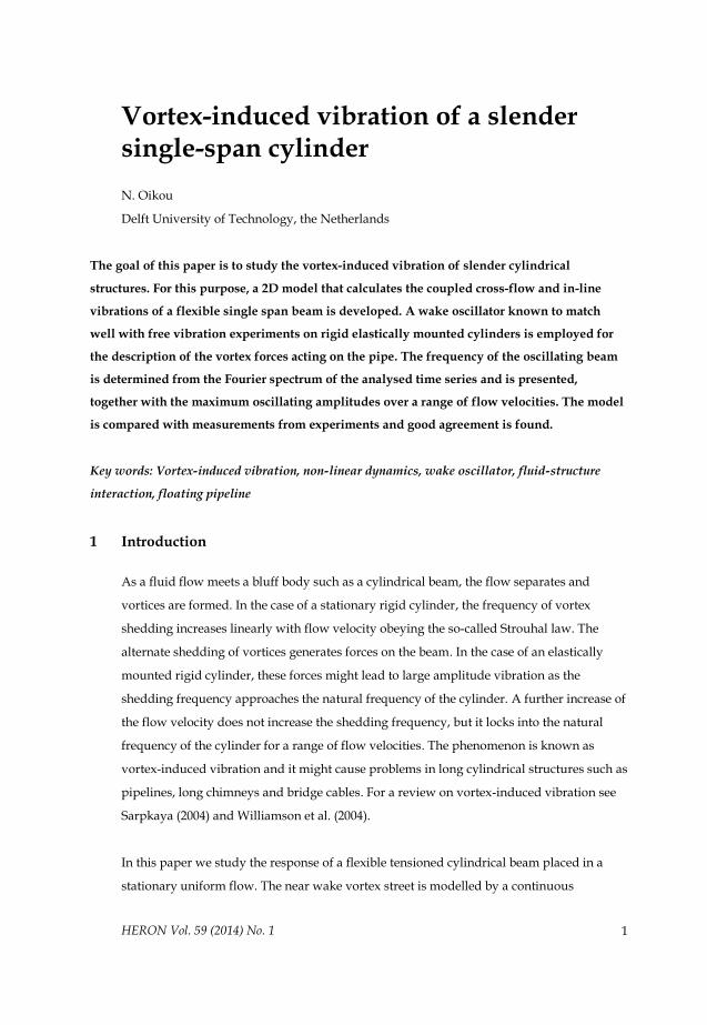
HERON Vol. 59 (2014) No. 1 1
Vortex-induced vibration of a slender single-span cylinder
N. Oikou
Delft University of Technology, the Netherlands
The goal of this paper is to study the vortex-induced vibration of slender cylindrical
structures. For this purpose, a 2D model that calculates the coupled cross-flow and in-line
vibrations of a flexible single span beam is developed. A wake oscillator known to match
well with free vibration experiments on rigid elastically mounted cylinders is employed for
the description of the vortex forces acting on the pipe. The frequency of the oscillating beam
is determined from the Fourier spectrum of the analysed time series and is presented,
together with the maximum oscillating amplitudes over a range of flow velocities. The model
is compared with measurements from experiments and good agreement is found.
Key words: Vortex-induced vibration, non-linear dynamics, wake oscillator, fluid-structure
interaction, floating pipeline
1 Introduction
As a fluid flow meets a bluff body such as a cylindrical beam, the flow separates and
vortices are formed. In the case of a stationary rigid cylinder, the frequency of vortex
shedding increases linearly with flow velocity obeying the so-called Strouhal law. The
alternate shedding of vortices generates forces on the beam. In the case of an elastically
mounted rigid cylinder, these forces might lead to large amplitude vibration as the
shedding frequency approaches the natural frequency of the cylinder. A further increase of
the flow velocity does not increase the shedding frequency, but it locks into the natural
frequency of the cylinder for a range of flow velocities. The phenomenon is known as
vortex-induced vibration and it might cause problems in long cylindrical structures such as
pipelines, long chimneys and bridge cables. For a review on vortex-induced vibration see
Sarpkaya (2004) and Williamson et al. (2004).
In this paper we study the response of a flexible tensioned cylindrical beam placed in a
stationary uniform flow. The near wake vortex street is modelled by a continuous
2
distribution of wake oscillators arranged along the cylinder length. Wake oscillator models
have been applied in the study of flexible structures before, see Mathelin et al. (2005) and
Violette et al. (2007), however lacking experimental validation. Ogink et al. (2010)
improved a model for the prediction of vortex-induced vibration on an elastically mounted
rigid cylinder in fluid flow developed by Facchinetti et al. (2004), by taking into account
the relative velocity between the flow and the cylinder motion. Their model was shown to
be able to tune easily to either the upper or lower branch of the free vibration experiments
such as those performed by Khalak et al. (1999). In this work we extend the couple wake-
cylinder model developed by Ogink et al. in order to simulate vortex-induced vibration on
long flexible cylinders, accounting for the relative velocity between the flow and the
cylinder motion. The model is compared to the measurements of Tsahalis (1984) and is
shown to yield realistic results.
2 Mathematical modelling of slender single-span cylinders
2.1 Force decomposition
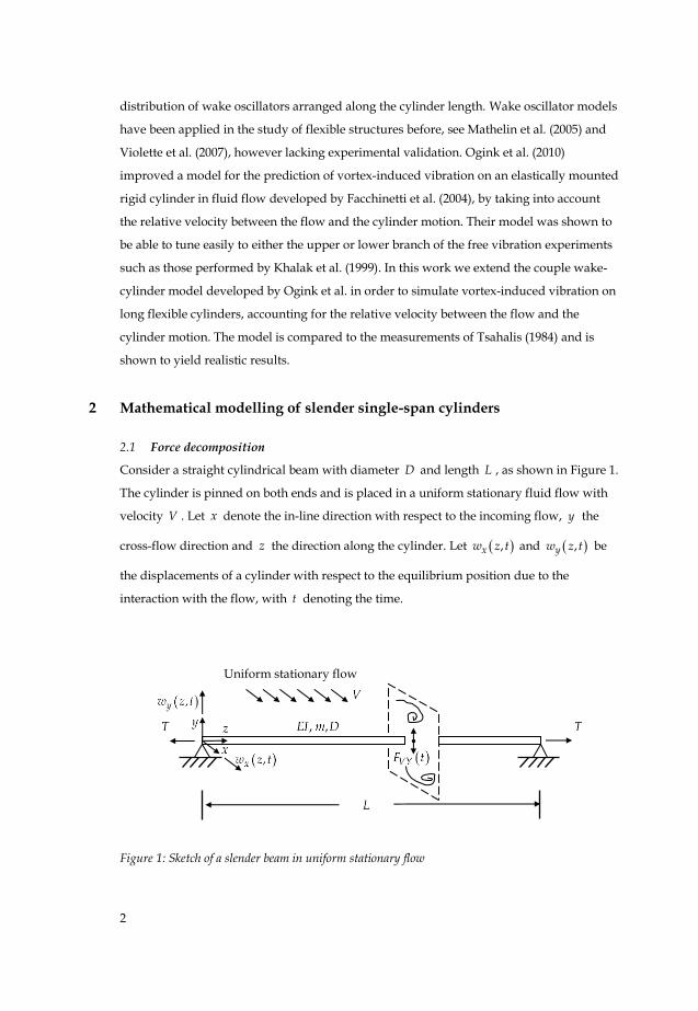
Consider a straight cylindrical beam with diameter D and length L , as shown in Figure 1.
The cylinder is pinned on both ends and is placed in a uniform stationary fluid flow with
velocity V . Let x denote the in-line direction with respect to the incoming flow, y the
cross-flow direction and z the direction along the cylinder. Let ,xw z t and ,yw z t be
the displacements of a cylinder with respect to the equilibrium position due to the
interaction with the flow, with t denoting the time.
Figure 1: Sketch of a slender beam in uniform stationary flow
Uniform stationary flow
•
3
Assume that the beam moves in the x y plane and that its length and the wavelength of
its deformation are large compared to its diameter, so that the Euler-Bernoulli theory is
applicable for the bending of the beam. With these assumptions, the equations that govern
the horizontal and vertical motion of a differential element of the cylinder can be written as
2 4 2
2 4 2x
a Vx x x
Xw
m m b EI T Ftt z z
w w w
, (1)
2 4 2
2 4 2
y y yV
ya Y
wm m b EI
w w wFT
tt z z
, (2)
in which m is the cylinder mass per unit length, am is the potential added mass per unit
length, b is the structural damping, EI is the cylinder bending stiffness, T is the axial
tension on the beam and VXF , VYF are the in-line and cross-flow forces per unit length
that are exerted on the beam due to the vortex shedding. The added mass am is given by
21 4a am C D , where is the fluid density and aC is the potential added mass
coefficient. The boundary conditions for the simply supported beam are given by
2 2
2 2
00 0x x
x xw w L
w w L EI EIz z
, (3)
2 2
2 2
00 0
y yy y
w w Lw w L EI EI
z z
. (4)
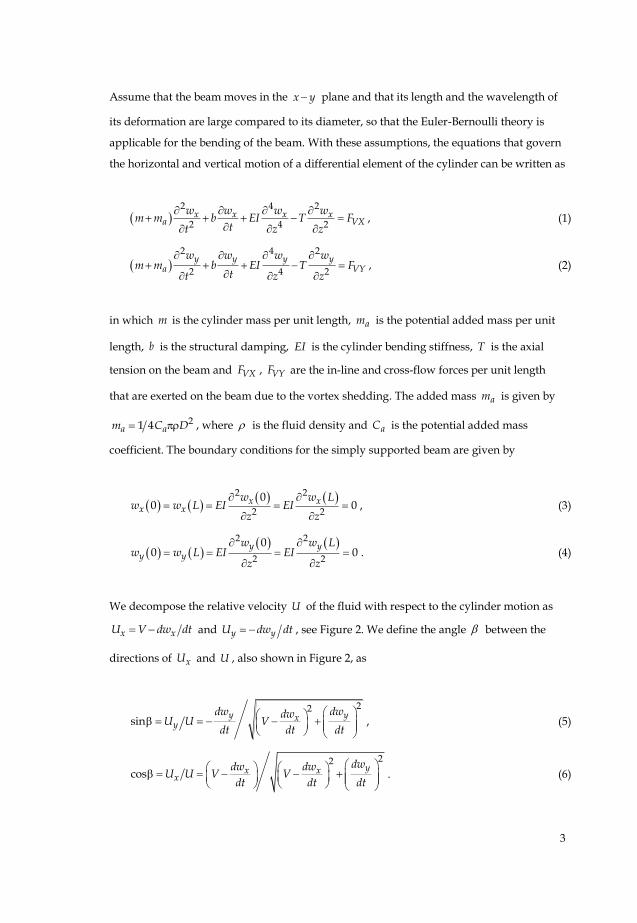
We decompose the relative velocity U of the fluid with respect to the cylinder motion as
x xU V dw dt and y yU dw dt , see Figure 2. We define the angle between the
directions of xU and U , also shown in Figure 2, as
22
siny yx
y
dw dwdwV
dt dt dtU U
, (5)
22
cosy
xx x
dwdw dwV VU U
dt dt dt
. (6)
4
Figure 2: Illustration of the relative velocity of the flow with respect to the cylinder motion and of
the vortex fluid forces exerted on a cross-section of the cylinder
Next, we follow Ogink (2010) and we decompose the vortex forces VXF and VYF in a lift
part VLF perpendicular to and a drag part VDF in-line with the relative velocity U , as
cos sinVX VD VLF F F , (7)
sin cosVY VD VLF F F . (8)
Using the dimensionless expressions 212VD VDC F DU and 21
2VL VLC F DU , the
vortex forces VXF and VYF can be expressed as
2( cos sin1
2)VX VD VLDUF C C , (9)
2( sin c )1
2osVD VLVYF D C CU . (10)
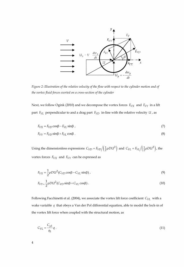
Following Facchinetti et al. (2004), we associate the vortex lift force coefficient VLC with a
wake variable q that obeys a Van der Pol differential equation, able to model the lock-in of
the vortex lift force when coupled with the structural motion, as
1
1
yVL
CC q
q . (11)
yy
dwU
dt
5
Here 1yC is the oscillating cross-flow force measured on a rigid stationary cylinder and 1q
is the amplitude of the limit cycle of the unforced wake oscillator, in our case 1 2q . The
vortex drag force VDC is associated with the mean in-line force 0xC measured on a rigid
stationary cylinder, as
0VD xC C . (12)
Facchinetti et al. compared a structural displacement, velocity and acceleration coupling,
and showed that the latter is dominant in the description of the cylinder forcing on the
wake oscillator. In these lines, an appropriate selection for a distributed wake oscillator
able to describe the cross flow force along the cylinder is given by
22
2 22 2
1y
s sq q wA
q qt Dt t
, (13)
where , A are tuning parameters for the model and s is the Strouhal angular
frequency given by 2s StV D , where St is the Strouhal number.
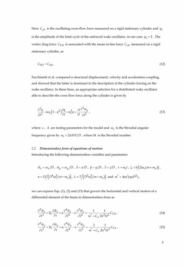
2.2 Dimensionless form of equations of motion
Introducing the following dimensionless variables and parameters
x xw w D , y yw w D , x x D , y y D , z z D , st , 2ωs ab m m ,
4 2ω asEI D m m , 2 2s aT D m m and * 24 ( )m m D ,
we can express Eqs. (1), (2) and (13) that govern the horizontal and vertical motion of a
differential element of the beam in dimensionless form as
2 4 2
2 4 2 * 3 2
1 12
2V
x
a
x x xXC
z z m C S
w w w
t
w
, (14)
2 4 2
2 4 2 * 3 2
1 12
2V
y
a
y y yYC
z z m C S
w w w
t
w
, (15)
6
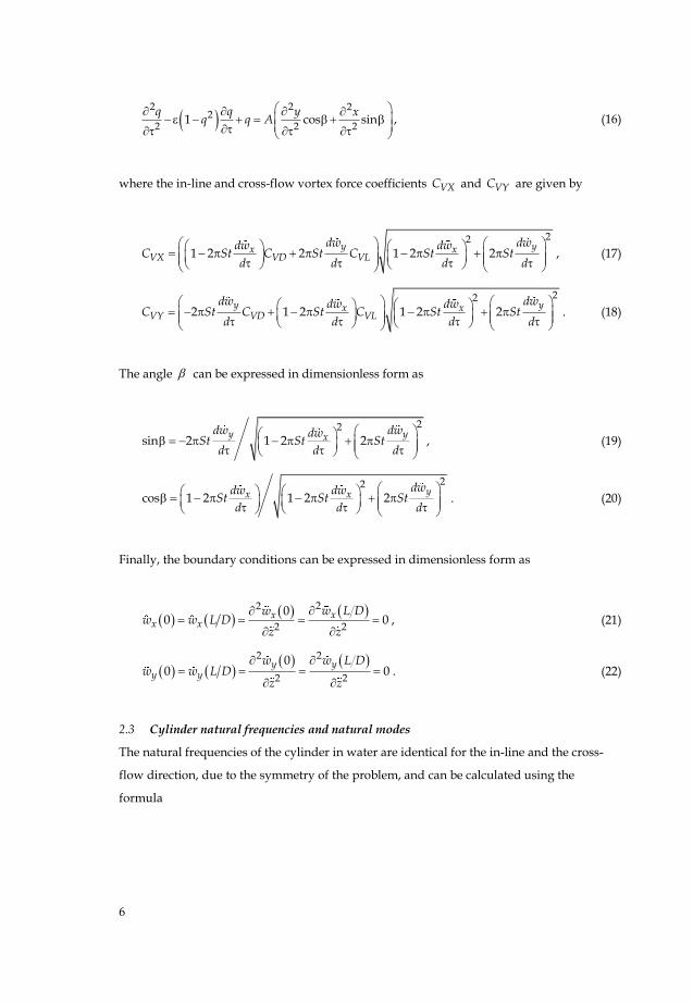
2 2 2
22 2 2
1 cos sinq q y x
q q A
, (16)
where the in-line and cross-flow vortex force coefficients VXC and VYC are given by
22
21 2 1 2 2y yx x
VX VD VL
dd dSt St St
d d d
dw ww wC C St C
d
, (17)
22
1 2 1 2 22y yx x
VY VD VL
dw ww w dd dSt SC St C C t t
d ddS
d
. (18)
The angle can be expressed in dimensionless form as
22
sin 2 1 2 2y yx
dw dwdwSt St St
d d d
, (19)
22
cos 1 2 1 2 2yx x
dwdw dwSt St St
d d d
. (20)
Finally, the boundary conditions can be expressed in dimensionless form as
22
2 2
00 0xx
x xw L Dw
w w L Dz z
, (21)
2 2
2 2
00 0
y yy y
w w L Dw w L D
z z
. (22)
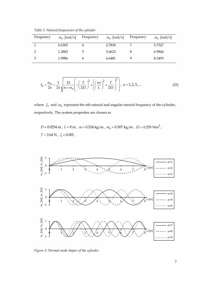
2.3 Cylinder natural frequencies and natural modes
The natural frequencies of the cylinder in water are identical for the in-line and the cross-
flow direction, due to the symmetry of the problem, and can be calculated using the
formula
7
Table 1: Natural frequencies of the cylinder
Frequency n [rad/s] Frequency n [rad/s] Frequency n [rad/s]
1 0.6305 4 2.7838 7 5.7527
2 1.2882 5 3.6622 8 6.9844
3 1.9986 6 4.6481 9 8.3493
22 21
f2 2 2 2
nn
a
T n T
m m EI L EI
, 1,2,3,...n . (23)
where nf and n represent the nth natural and angular natural frequency of the cylinder,
respectively. The system properties are chosen as
0.0254 mD , 8 mL , 0.524 kg mm , 0.507 kg mam , 20.255 NmEI ,
2.64 NT , 0.001 .
Figure 3: Normal mode shapes of the cylinder
-1
0
1
0 1 2 3 4 5 6 7 8
wy [
m],
wx [
m]
z [m]
n=1
n=2
n=3
-1
0
1
0 1 2 3 4 5 6 7 8
wy [
m],
wx [
m]
z [m]
n=4
n=5
n=6
-1
0
1
0 1 2 3 4 5 6 7 8
wy [
m],
wx [
m]
z [m]
n=7
n=8
n=9
8
and correspond to a PVC cylinder. The first nine natural frequencies of the cylinder are
presented in Table 1. The corresponding natural modes of the cylinder oscillation are
calculated using the formula
22
, , 2
41 2w w sin 2
2
a ny n x n
m mT Tz z z
EI EIEI
, 0,z L , 1,2,3,...n . (24)
and are presented in Figure 3. For a derivation of Eqs. (23)-(24), see Bokaian (1990).
3 Numerical implementation and discussion
The coupled system of partial differential equations (14) - (16) was solved numerically in
Fortran by approximating the spatial derivatives with a second order finite difference
scheme and integrating the resulting set of ordinary differential equations in time using a
fifth order Runge-Kutta scheme. The spatial discretization was chosen as 0.05 mz and
the time step was equal to 100sT , where sT stands for the period of the Strouhal
frequency. The initial conditions were chosen as
0yw , 0ydw dz , 0xw , 0xdw dz , 0.1q and 0dq dz .
The values for 0xC , 1yC , St were taken from the measurements of Gopalkrishnan (1993)
on stationary cylinders and are equal to 0 1.1856xC , 1 0.3842yC and 0.1932St . The
potential added mass coefficient aC is equal to 1 and the tuning parameters of the wake
oscillator are chosen as 0.7 , 12A .
The mean displacement in the x direction was calculated from a time series with a length
of 100 periods. The maximum recurrent cross-flow and in-line displacement at a given
position along the cylinder was found from a time series with a length of 100 periods and
the oscillating frequency c was determined by the highest peak in the Fourier spectrum
of the analysed time series. The calculation was repeated over a range of flow velocities in
order to search for lock-in over higher natural frequencies of the cylinder.
9
All calculations were performed twice, in order to search for hysteresis, once where the
initial conditions were equal to the last lower flow velocity and once in backward
direction, where the initial conditions were equal to the last higher flow velocity. The
steady state was typically reached after 50 periods of oscillation. The model results were
verified by comparing them to a numerical solution using modal superposition and good
agreement between the two solutions was found.
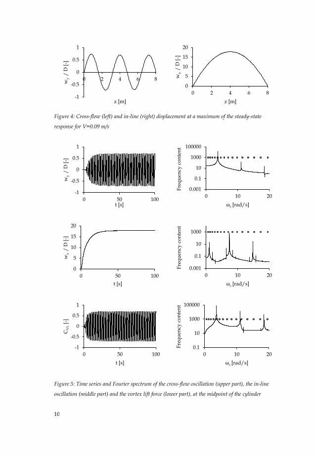
The cross-flow and in-line displacements along the cylinder at a maximum of the cross-
flow amplitude are shown in Figure 4 for V=0.09 m/s. This velocity corresponds to a
Strouhal frequency equal to 4.3 rad/s. The cross-flow amplitude resembles the fifth mode
shape of the cylinder. As shown in Figure 5, the cross-flow vibration occurs at a frequency
equal to 3.69 rad/s, close its fifth natural frequency. The circles in the frequency spectra
denote the natural frequencies of the cylinder in the shown range. The vortex lift force
oscillates at the exact same frequency, which means that the vortex-shedding is
synchronized to the vibration frequency, not obeying the Strouhal law. This is in
agreement with observations on vortex-induced vibrations of one-degree of freedom rigid
elastically mounted cylinders, see for example Gopalkrishnan (1993).
The mean displacement in the in-line direction at 4 mz is equal to 18D , a relatively
high value, probably due to the low bending stiffness of the cylinder. The maximum in-line
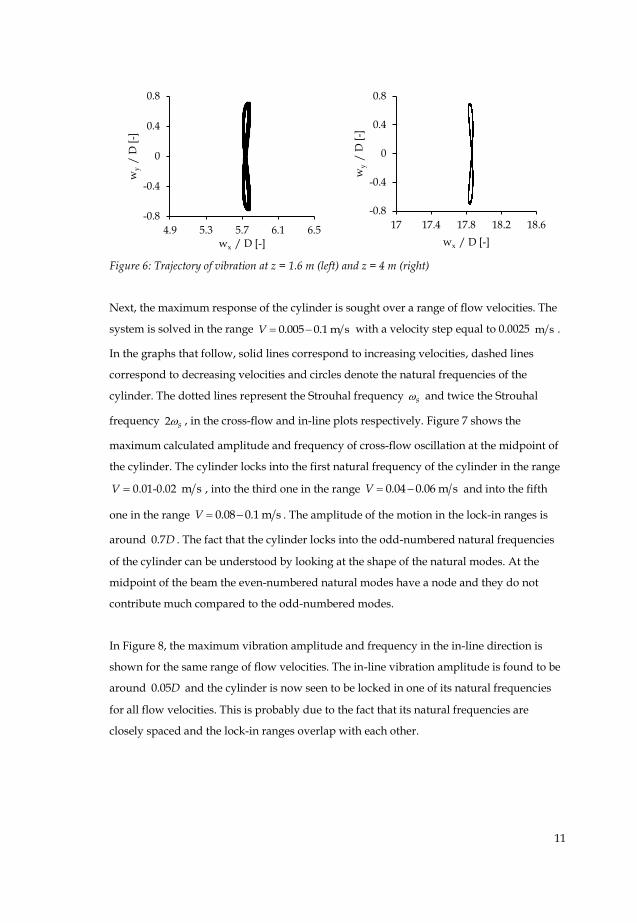
vibration amplitude at the same location is less than 0.1D , hence it can be hardly seen in
Figure 5 (middle, left). It can be also observed that the in-line vibration frequency is 7.38
rad/s, twice as much as the cross-flow vibration frequency. This results in the
characteristic figure-eight trajectory, which can be seen in Figure 6 for two different
locations along the cylinder, close to two of the antinodes of its fifth mode shape.
10
Figure 4: Cross-flow (left) and in-line (right) displacement at a maximum of the steady-state
response for V=0.09 m/s
Figure 5: Time series and Fourier spectrum of the cross-flow oscillation (upper part), the in-line
oscillation (middle part) and the vortex lift force (lower part), at the midpoint of the cylinder
-1
-0.5
0
0.5
1
0 2 4 6 8
wy
/
D [
-]
z [m]
0
5
10
15
20
0 2 4 6 8
wx
/ D
[-]
z [m]
-1
-0.5
0
0.5
1
0 50 100
wy
/
D [
-]
t [s]
0.001
0.1
10
1000
100000
0 10 20
Fre
qu
ency
co
nte
nt
ωc [rad/s]
0
5
10
15
20
0 50 100
wx
/ D
[-]
t [s]
0.001
0.1
10
1000
0 10 20
Fre
qu
ency
co
nte
nt
ωc [rad/s]
-1
-0.5
0
0.5
1
0 50 100
CV
L [
-]
t [s]
0.1
10
1000
100000
0 10 20
Fre
qu
ency
co
nte
nt
ωc [rad/s]
11
Figure 6: Trajectory of vibration at z = 1.6 m (left) and z = 4 m (right)
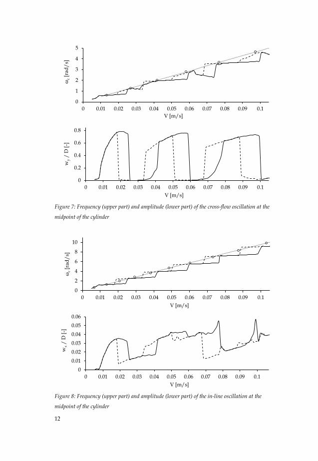
Next, the maximum response of the cylinder is sought over a range of flow velocities. The
system is solved in the range 0.005 0.1 m sV with a velocity step equal to 0.0025 m s .
In the graphs that follow, solid lines correspond to increasing velocities, dashed lines
correspond to decreasing velocities and circles denote the natural frequencies of the
cylinder. The dotted lines represent the Strouhal frequency s and twice the Strouhal
frequency 2 s , in the cross-flow and in-line plots respectively. Figure 7 shows the
maximum calculated amplitude and frequency of cross-flow oscillation at the midpoint of
the cylinder. The cylinder locks into the first natural frequency of the cylinder in the range
V 0.01-0.02 m s , into the third one in the range 0.04 0.06 m sV and into the fifth
one in the range 0.08 0.1 m sV . The amplitude of the motion in the lock-in ranges is
around 0.7D . The fact that the cylinder locks into the odd-numbered natural frequencies
of the cylinder can be understood by looking at the shape of the natural modes. At the
midpoint of the beam the even-numbered natural modes have a node and they do not
contribute much compared to the odd-numbered modes.
In Figure 8, the maximum vibration amplitude and frequency in the in-line direction is
shown for the same range of flow velocities. The in-line vibration amplitude is found to be
around 0.05D and the cylinder is now seen to be locked in one of its natural frequencies
for all flow velocities. This is probably due to the fact that its natural frequencies are
closely spaced and the lock-in ranges overlap with each other.
-0.8
-0.4
0
0.4
0.8
4.9 5.3 5.7 6.1 6.5
wy
/
D [
-]
wx / D [-]
-0.8
-0.4
0
0.4
0.8
17 17.4 17.8 18.2 18.6
wy
/
D [
-]
wx / D [-]
12
Figure 7: Frequency (upper part) and amplitude (lower part) of the cross-flow oscillation at the
midpoint of the cylinder
Figure 8: Frequency (upper part) and amplitude (lower part) of the in-line oscillation at the
midpoint of the cylinder
0
1
2
3
4
5
0 0.01 0.02 0.03 0.04 0.05 0.06 0.07 0.08 0.09 0.1
ωc
[ra
d/
s]
V [m/s]
0
0.2
0.4
0.6
0.8
0 0.01 0.02 0.03 0.04 0.05 0.06 0.07 0.08 0.09 0.1
wy /
D [
-]
V [m/s]
0
2
4
6
8
10
0 0.01 0.02 0.03 0.04 0.05 0.06 0.07 0.08 0.09 0.1
ωc
[ra
d/
s]
V [m/s]
0
0.01
0.02
0.03
0.04
0.05
0.06
0 0.01 0.02 0.03 0.04 0.05 0.06 0.07 0.08 0.09 0.1
wx /
D [
-]
V [m/s]
13
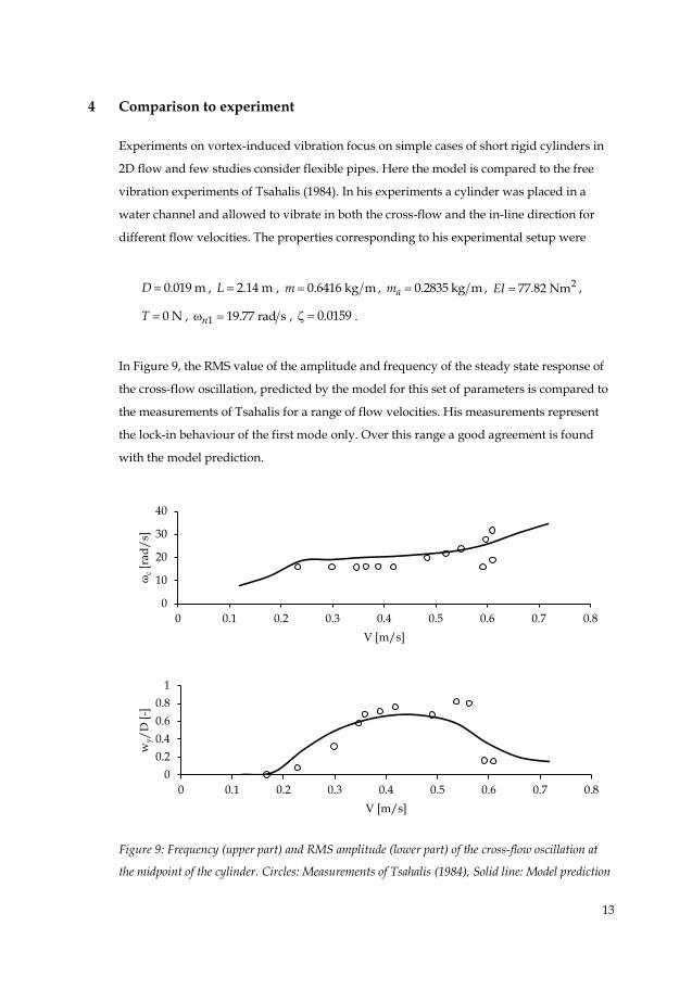
4 Comparison to experiment
Experiments on vortex-induced vibration focus on simple cases of short rigid cylinders in
2D flow and few studies consider flexible pipes. Here the model is compared to the free
vibration experiments of Tsahalis (1984). In his experiments a cylinder was placed in a
water channel and allowed to vibrate in both the cross-flow and the in-line direction for
different flow velocities. The properties corresponding to his experimental setup were
0.019 mD , 2.14 mL , 0.6416 kg mm , 0.2835 kg mam , 277.82 NmEI ,
0 NT , 1 19.77 rad sn , 0.0159 .
In Figure 9, the RMS value of the amplitude and frequency of the steady state response of
the cross-flow oscillation, predicted by the model for this set of parameters is compared to
the measurements of Tsahalis for a range of flow velocities. His measurements represent
the lock-in behaviour of the first mode only. Over this range a good agreement is found
with the model prediction.
Figure 9: Frequency (upper part) and RMS amplitude (lower part) of the cross-flow oscillation at
the midpoint of the cylinder. Circles: Measurements of Tsahalis (1984), Solid line: Model prediction
0
10
20
30
40
0 0.1 0.2 0.3 0.4 0.5 0.6 0.7 0.8
ωc
[ra
d/
s]
V [m/s]
0
0.2
0.4
0.6
0.8
1
0 0.1 0.2 0.3 0.4 0.5 0.6 0.7 0.8
wy/
D [
-]
V [m/s]
14
5 Conclusions
In this work we extended an existing wake-cylinder model in order to study the response
of a free spanning cylindrical beam subject to a uniform stationary flow. The model does
not require any a priori assumptions about the frequency and the mode of vibration,
making it possible to predict multimode excitation. The frequency spectra of the cross-flow
oscillation at the midpoint of the cylinder show that vibration occurs in well-defined
frequency bands for certain lock-in velocity ranges, in which the vortex shedding is
synchronized to the frequency of the cross-flow vibration, not obeying the Strouhal law. In
the same velocity range, the in-line vibration frequency is found to be double the frequency
of the cross-flow oscillation and the cylinder trajectory follows the characteristic figure-
eight pattern. The model is compared to free vibration measurements on flexible horizontal
cylinders and good agreement is found.
The coupled wake-oscillator model is faster and easier to apply compared to the
Computational Fluid Dynamics (CFD) models and is more effective in modelling vortex-
induced vibration than single variable models. The model can be easily extended to model
multi-span and variable tension (vertical) long cylindrical structures prone to vortex-
induced vibration.
Literature
Bokaian, A. (1990). Natural frequencies of beams under tensile axial loads. Journal of Sound
and Vibration, 142(3), 481-498.
Facchinetti, M. L., de Langre, E., & Biolley, F. (2004). Coupling of structure and wake
oscillators in vortex-induced vibrations. Journal of Fluids and structures, 19(2), 123-140.
Gopalkrishnan, R. (1993). Vortex-induced forces on oscillating bluff cylinders. Ph.D. thesis,
Massachusetts Institute of Technology.
Khalak, A., & Williamson, C. H. K. (1999). Motions, forces and mode transitions in vortex-
induced vibrations at low mass-damping. Journal of Fluids and Structures, 13(7), 813-851.
Mathelin, L., & De Langre, E. (2005). Vortex-induced vibrations and waves under shear
flow with a wake oscillator model. European Journal of Mechanics-B/Fluids, 24(4), 478-
490.
15
Ogink, R. H. M., & Metrikine, A. V. (2010). A wake oscillator with frequency dependent
coupling for the modeling of vortex-induced vibration. Journal of Sound and
Vibration, 329(26), 5452-5473.
Sarpkaya, T. (2004). A critical review of the intrinsic nature of vortex-induced
vibrations. Journal of Fluids and Structures, 19(4), 389-447.
Tsahalis, D. T. (1984). Vortex-induced vibrations of a flexible cylinder near a plane
boundary exposed to steady and wave-induced currents. Journal of Energy Resources
Technology, 106(2), 206-213.
Violette, R., De Langre, E., & Szydlowski, J. (2007). Computation of vortex-induced
vibrations of long structures using a wake oscillator model: Comparison with DNS and
experiments. Computers & Structures, 85(11), 1134-1141.
Williamson, C. H. K., & Govardhan, R. (2004). Vortex-induced vibrations. Annu. Rev. Fluid
Mech., 36, 413-455.