Embed Size (px)
Citation preview
Minor design changes or otherwise may result in slight variations between the product illustrated and that which is contained within this package
THE QUALITY BRAND IN FANS
INSTALLATION AND OPERATION INSTRUCTION BOOK, REV 2.0
DOMINO SERIES
MODELS: BH151ESWWH, BH151ESWSL
BATHROOM HEATER WITH EXHAUST FAN AND LED LIGHT
CAUTION!
READ ALL SAFETY PRECAUTIONS AND INSTRUCTIONS CAREFULLY BEFORE INSTALLATION AND OPERATION.

TABLE OF CONTENTS
A Rev 2.0
Mercator Pty Ltd. All Rights Reserved.
INTRODUCTION & SPECIFICATIONS .............................................................................................................................. 1
SAFETY PRECAUTIONS ........................................................................................................................................................ 2
UNPACKING YOUR HEATER .............................................................................................................................................. 3
CHOOSING A PROPER LOCATION .................................................................................................................................... 4
INSTALLATION INSTRUCTIONS ....................................................................................................................................... 6
WIRING DIAGRAM .............................................................................................................................................................. 11
CARE AND MAINTENANCE ............................................................................................................................................. 12

INTRODUCTION & SPECIFICATIONS
1 Rev 2.0
Mercator Pty Ltd. All Rights Reserved.
CONGRATULATIONS ON YOUR CHOICE
Thank you and we are delighted you have chosen a MERCATOR bathroom heater for your home. Please read all instructions carefully before assembly and use.
SAFETY NOTICES
WARNING / CAUTION
A WARNING / CAUTION notice denotes a hazard. It calls attention to an installation procedure, operating procedure, maintenance procedure, or the like, that if not correctly performed or adhered to, could result in damage to this product, personal injury or death. Do not proceed beyond a WARNING / CAUTION notice until the indicated conditions are fully understood and met.
SAFETY SYMBOLS
Alternating current
Protective earth
Warning/Caution
PRODUCT SPECIFICATIONS
MODEL OPERATING
VOLTAGE
OPERATING
FREQUENCY
HEATER
POWER
EXHAUST
FAN
POWER
LIGHT
POWER
DUCT
OUTLET
AIR
VOLUME
NET
WEIGHT
BH151ESW 220-240V~ 50Hz 800W 60W
2 x 10W
LED
Panel,
3000K
⌀150mm 500m3/h 7.9kg
SAFETY FEATURE
This appliance is protected from overheating. When power to heat lamp is switched on and sensed
temperature inside housing reaches 75˚C, fan starts running automatically to help disperse heat. For
additional protection, heat lamp will be cut off temporarily by a resettable thermostat if temperature
reaches 115˚C or permanently by a non-resettable fuse should temperature reaches 135˚C.

SAFETY PRECAUTIONS
2 Rev 2.0
Mercator Pty Ltd. All Rights Reserved.
Please observe the following general safety precautions carefully before and during all phases of handling, installation, removal, operation and maintenance of this product. Failure to comply with these precautions violates safety standards of design, manufacture and intended use of the product. Mercator assumes no liability for customer’s failure to comply with these requirements.
SAFETY WARNINGS
1. Read and follow all instructions, safety information and assembly diagrams in this manual. 2. Before any work on the product is undertaken, all supply circuits and powers must be
disconnected by switching off the mains supply circuit breaker, to ensure all pole isolation of the electrical supply.
3. This product must be installed by a licensed and qualified electrician in accordance to AS/NZS 3000 Wiring Rules and applicable local authority regulations.
4. Means for disconnection of the appliance from mains supply must be incorporated in the fixed wiring in accordance with the wiring rules.
5. It is the responsibility of qualified, licensed installer and user to apply common sense and care at all times during installation, maintenance and operation of the appliance.
6. This product is not intended for use by persons (including children) with reduced physical, sensory or mental capabilities, or lack of experience and knowledge, unless they have been given supervision or instruction concerning safe use of the product by a responsible person.
7. Children should be supervised to ensure that they do not play with the product. 8. The product is to be installed in a location so that the switches and other controls CANNOT be touched
by a person in the bath or shower. 9. Do not install the product directly above shower cubicle or bath enclosure or a location where water
will splash onto it. 10. Do not install the product close to curtains and other combustible materials. 11. The product must, under no circumstances, be covered with insulating material or similar
material on the sides or rear of the unit to avoid overheating. 12. This product must be installed so that the relevant national regulations and Australian Building Code
requirements concerning ventilation and the discharge of air are fulfilled. 13. Do not cut or notch joists, beams and rafters to install the product. 14. Do not damage hidden electrical wirings or utilities when making the ceiling cut. 15. This product must be earthed. 16. Do use a power cable with a minimum 10A rating. 17. Do not use the heater if the heat lamp is cracked, broken or damaged. 18. Do not look directly at the heat lamps when in use. 19. Check and confirm after the product is completely installed that all connections are proper and secure
to prevent the product from falling, causing property damages or injury. 20. Do not probe through the fascia opening. 21. Use only heat lamps and lighting lamps approved by MERCATOR. 22. Use only wall controllers approved by MERCATOR. Do not use electronic or solid state wall controllers. 23. Do not install or use the product outdoor where it could be exposed to water or moisture (indoor use
only). 24. This manual is not intended to instruct or assist untrained or unqualified persons to install this product. 25. It is the responsibility of qualified, licensed installer and user to apply common sense and care at all
times during installation and maintenance. 26. Always turn off the product and ensure the heat lamps and motor have completely cooled down before
servicing or cleaning the exhaust fan or lamps.

UNPACKING YOUR HEATER
3 Rev 2.0
Mercator Pty Ltd. All Rights Reserved.
INCLUDED WITH YOUR HEATER
Open the original carton and verify the following items are available for the standard purchase of this product. It there are any missing or mechanically damaged items, contact the Mercator Customer Care. Do not throw away the carton or other packaging material as it may be needed if warranty replacement or repair is ever necessary.
1 x bathroom heater with 2 x 10W LED panels 1 x 800W linear heat lamp 1 x 1.5m ⌀150mm flexible duct 1 x 3 gang switch wall controller 2 x clamps 1 x external wall grille 1 x cut out template 1 x instruction book 1 x warranty card
Use of an unapproved wall controller voids the warranty. Therefore do not control the operation of this product from any wall controller that is not approved by Mercator for use with this product.
Do not use solid state controllers.

CHOOSING A PROPER LOCATION
4 Rev 2.0
Mercator Pty Ltd. All Rights Reserved.
HOW TO CHOOSE A PROPER LOCATION FOR HEATER
This product can be installed in places that require direct radiant heating and circulated air flow such as bathrooms, ensuites and laundries. Consideration on safety
1. Do not install the product directly above shower cubicle or bath enclosure 2. Do not install the product in a location where there is a possibility of water will splashing onto
the lamps or the switches being touched by a person in the bath or shower.
Consideration on ventilation
1. It is very important that air is allowed to enter the room being ventilated. This can be done by increasing gap under the door, installing door grilles or opening windows. It is impossible to exhaust more air from a room than is allowed to enter it.
2. The product should be positioned to ensure ventilation air traversing the room provides ventilation to all areas. Avoid positioning the product too close to windows or doors as such positioning cut short the airflow path and does not provide proper ventilation. Ensure air is ventilated to outside through ductwork. Precaution must be taken to avoid the back-flow of gases into the room from the open flue of gas or other fuel-burning appliances.
Consideration on orientation
3. The product must be horizontally mounted on a ceiling and not on a wall or a raked ceiling. 4. It is recommended that the air outlet points towards an outer wall and the ductworks
interconnecting the air outlet and the external grille are laid in a straight fashion. If it is desirable for ductworks to run across any timber structures such as rafter, stud or joist, ensure the closest structure is not within 300mm of the air outlet.
Consideration on clearances
5. Ensure the air outlet of the product is not directed to or close to a rafter or stud allowing draft stopper on the outlet to fully open when fan is turned on.
6. Ensure at least 2.1 meters between the product fascia and the floor. 7. Ensure at least 235 mm clearance above the ceiling for installation. 8. Ensure at least 50 mm between the sides of the heater and any building element adjacent to it. 9. Ensure at least 1.0 meter between the sides of the heater and the sides of any adjacent heater,
as well as at least 1.0 meter away from combustible objects such as curtains. 10. Do not cut or notch joists, studs, beams and rafters to install the product. 11. Before installation, ensure that there is no hidden electrical wiring or utility behind the spot
where the opening is going to be made. Check and plan for the wiring route carefully. 12. Ensure the ceiling is strong enough to support the weight of at least 10 kg.
Domino Fascia size 560 mm x 360 mm Cut out size 540 mm x 320 mm Product height without fascia 207 mm Product height including fascia 222 mm

CHOOSING A PROPER LOCATION
5 Rev 2.0
Mercator Pty Ltd. All Rights Reserved.
RECOMMENDATION ON DUCTING INSTALLATION
1. Plan the required length of duct carefully; cutting off excessive length of duct and ensuring ducting is as short as possible.
2. Ensure ducting is fully extended, properly supported, straight and not slacking. 3. Ensure ducting is not obstructed or squeezed. 4. Avoid bending the duct. 5. Do not use ducting with a diameter smaller than the diameter of the outlet, or the collar of the
grille to which the duct is connected. 6. Secure ducting connection properly using clamp, cable tie or tape.

INSTALLATION INSTRUCTIONS
6 Rev 2.0
Mercator Pty Ltd. All Rights Reserved.
Make sure electricity is turned off at the main power box before commencing work. Turn off the power by removing fuse or turning off circuit breaker before installing the product and replacing lamp.
Make sure that ceiling joists are strong enough and of adequate size to support the weight of at least 35 kg.
1. Take some time choosing an appropriate mounting location and direction with reference to instructions in previous page. Make sure all clearances required around the product are observed and there is no obstructing structure nearby the outlet. The area behind the intended location must be clear of obstacles such as cables, utility pipes and joists.
INSTALLING GRILLE ON WALL
2. Mark out a circle of the base diameter at desired location. Using an appropriate cutting device, cut along the line and remove excess material from the marked location.
3. Remove louver from the base of grille noting there are four screw holes on the base. Push a duct through the hole and connect it to the collar of the base. Secure the ducting connection with the clamp provided. Then fix the base at the desired spot using four suitable screws (not provided). Install louver onto the base. Install ductwork following recommendation on ducting installation in previous page, and direct the duct towards general direction of cut out and air outlet on the product.
INSTALLING BATHROOM HEATER
4. Use a pencil and trace around the template supplied the package.

INSTALLATION INSTRUCTIONS
7 Rev 2.0
Mercator Pty Ltd. All Rights Reserved.
5. Using an appropriate cutting device, cut along the line and remove excess material from the ceiling. If necessary provide additional support to the ceiling. Tips:
Do not cut the hole any larger than the specified cut out dimension.
6. Remove fascia from the main unit with care by pressing the two spring levers attached to rear of fascia and disconnect lamp wire.
7. Remove wiring box cover to access terminal block by loosening four screws. Check the air outlet and remove any adhesive tape holding draft stopper in place to allow free movement in operation.

INSTALLATION INSTRUCTIONS
8 Rev 2.0
Mercator Pty Ltd. All Rights Reserved.
8. Remove the sticky tape on the draft stopper
9. Draw wires out from cut out hole and make wiring connection in accordance to the wiring diagram provided. The product must be earthed during installation. Connect ducting to outlet and secure its connection. Insert heater into cut out hole at an angle ensuring duct connection is intact and no cable or insulating material rest over or against the heater. Make sure side clamps are pulled inwards so that the rest of housing can pass through the hole without damaging plaster board. Tips: Do not overtighten clamp when securing ducting to air outlet to allow draft stopper fully open in operation.

INSTALLATION INSTRUCTIONS
9 Rev 2.0
Mercator Pty Ltd. All Rights Reserved.
10. Ensure the unit is held securely in place by the pushing side clips outwards and tighten the screws until main unit rests flush to the ceiling
INSTALLATION INSTRUCTIONS
10 Rev 2.0
Mercator Pty Ltd. All Rights Reserved.
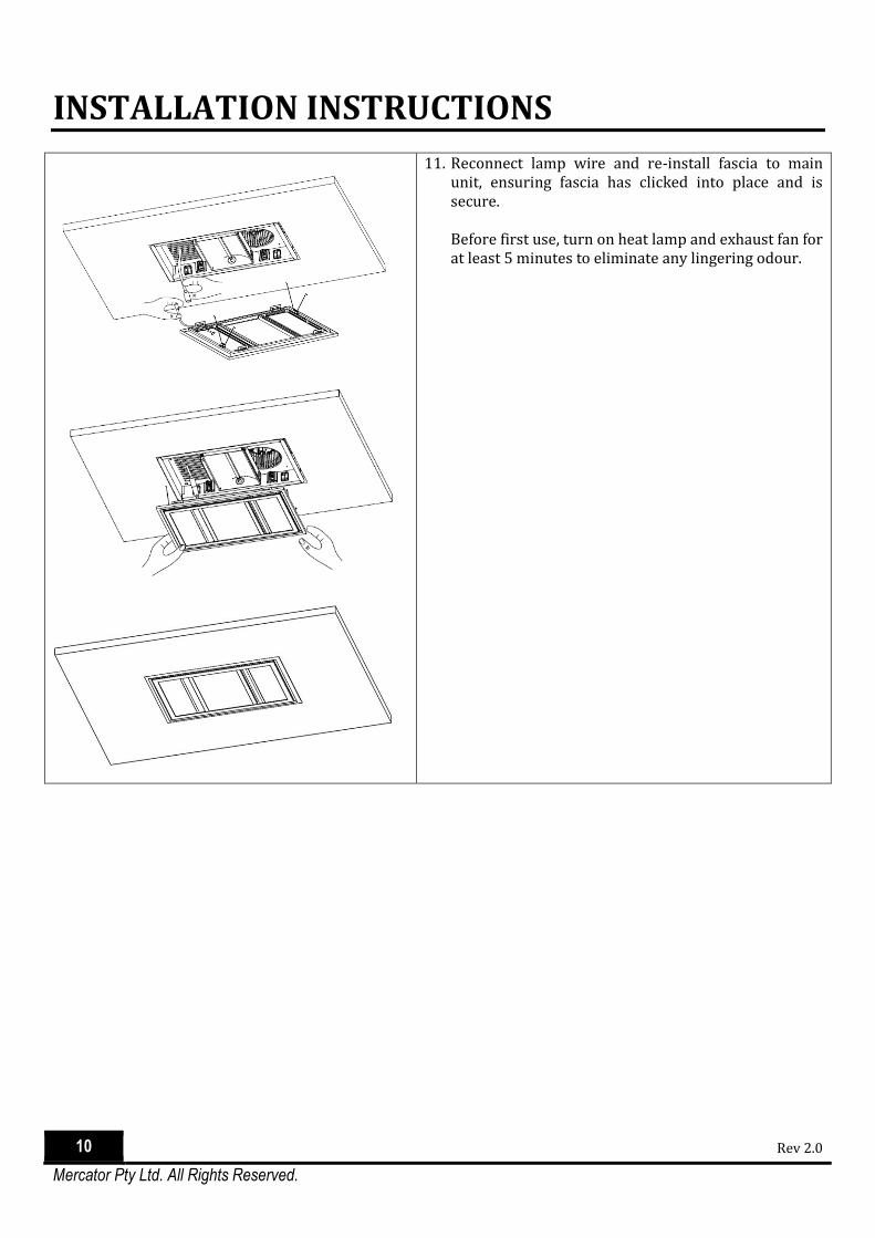
11. Reconnect lamp wire and re-install fascia to main unit, ensuring fascia has clicked into place and is secure. Before first use, turn on heat lamp and exhaust fan for at least 5 minutes to eliminate any lingering odour.

WIRING DIAGRAM
11 Rev 2.0
Mercator Pty Ltd. All Rights Reserved.
WIRING DIAGRAM
ALL POLE DISCONNECTION FROM THE SUPPLY MAINS MUST BE INCORPORATED IN THE FIXED WIRING IN ACCORDANCE WITH AS/NZS 3000 IN ADDITION TO WALL CONTROLLER SUPPLIED
WALL CONTROLLER INSTALLATION INSTRUCTION
Do not mount wall controller near heat producing equipment. The wall controller provided is designed to be connected with the product supplied in this package
only. Other uses may cause personal injury or fire hazard. Make sure electricity is turned off at the main power box before commencing work. Turn off the
power by removing fuse or turning off circuit breaker before installing the wall controller.
HOW TO INSTALL WALL CONTROLLER
1. Disconnect the power and remove the existing wall plate and switch (if any). 2. Tighten screws on the terminal blocks and make sure wire connections are secure. 3. Secure the wall controller to the wall with two screws provided.
CARE AND MAINTENANCE
12 Rev 2.0
Mercator Pty Ltd. All Rights Reserved.
1. Make sure electricity is turned off at the mains power box before commencing work. Turn-off the power by removing fuse or turning off circuit breaker before installing the appliance.
2. Allow the appliance to cool completely before commencing work.
CARE
1. To prolong the useful life of this product, avoid using heat lamp alone for longer than 10 minutes. Using the fan function along with heat lamp helps cooling the product.
CLEANING & MAINTENANCE
1. After power is turned off and the appliance is cool, wipe the outer surface with a clean cloth dampened with petroleum-free detergent or liquid glass cleaner.
2. Do not use alcohol cleaner, or thinner or liquid that is corrosive to plastic for cleaning. 3. Dry the product completely before re-use.
HOW TO REPLACE HEAT LAMP
The heat lamp requires replacement when operation lifetime is reached.
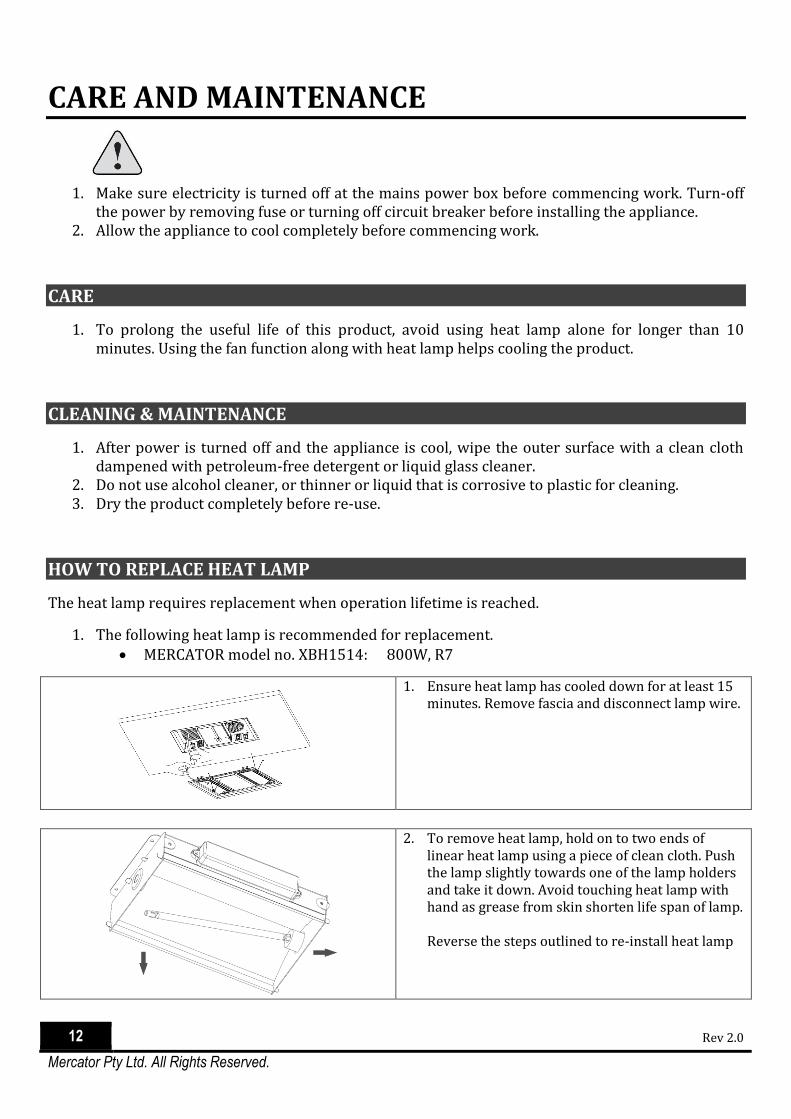
1. The following heat lamp is recommended for replacement. MERCATOR model no. XBH1514: 800W, R7
1. Ensure heat lamp has cooled down for at least 15 minutes. Remove fascia and disconnect lamp wire.
2. To remove heat lamp, hold on to two ends of linear heat lamp using a piece of clean cloth. Push the lamp slightly towards one of the lamp holders and take it down. Avoid touching heat lamp with hand as grease from skin shorten life span of lamp. Reverse the steps outlined to re-install heat lamp

CARE AND MAINTENANCE
13 Rev 2.0
Mercator Pty Ltd. All Rights Reserved.
HOW TO REPLACE LED LIGHT
The integrated fascia assembly can be replaced when operation lifetime of LED lamp is reached.
1. The following fascia is recommended for replacement. Mercator Model no. XBH1511WH: Domino fascia, White Mercator Model no. XBH1511SL: Domino fascia, Silver Mercator Model no. XBH1511BK: Domino fascia, Black
PLEASE RECYCLE ALL PACKAGING MATERIAL SUPPLIED WITH THIS PRODUCT