Embed Size (px)
Citation preview

GODDARD SPACE FLIGHT CENTERGODDARD SPACE FLIGHT CENTER
The New Millennium Program ST8 Thermal Loop Experiment
Jentung Ku, Thai PhamDonya Douglas, Laura Ottenstein
NASA Goddard Space Flight CenterGreenbelt, Maryland 20771
(301) [email protected]
Thermal and Fluid Analysis WorkshopAugust 7-11, 2006, College Park, Maryland
8/8/2006 TFAWS-2006 2
Outline
• Overview of NMP Space Technology 8 (ST8) Project and Thermal Loop Experiment
• Description of Thermal Loop Experiment• Summary of Thermal Loop TRL 4 Validation Results• Summary of Thermal Loop TRL 5 Validation Results• Thermal Loop Protoflight Unit for TRL 7 Validation• Thermal Loop Development Status• Summary and Conclusion

8/8/2006 TFAWS-2006 3
Thermal Loop Experiment Description and Objective
• Thermal Loop experiment is an advanced thermal control system consisting of a miniature loop heat pipe with multiple evaporators and condensers designed for future small system applications requiring low mass, low power, and compactness.
• The TL technology will benefit future systems by outperforming conventional satellite thermal management approaches based solely on MLI, auxiliary heaters, conventional conduction heat sinks, louvers, conventional heat pipes, and radiators while providing flexibility in system testing configuration and component placement.
• The objective is to validate in space a miniature loop heat pipethermal control system capable of reliable start-ups, steady operation, heat load sharing, and tight temperature control between 273K and 308K.

8/8/2006 TFAWS-2006 4
Thermal Loop is Part of ST8 Mission
• The Thermal Loop technology will be validated as part of the NewMillennium Program Space Technology 8 (ST8) mission.
• ST8 is a JPL managed project with the purpose to advance the maturity of four technologies from “validated in a laboratory environment” (TRL 4) to “demonstrated in a space environment” (TRL 7).
• The four experiments will be integrated on an Orbital Sciences Corporation (OSC) spacecraft bus.
• ST8 is a seven month mission including one month of checkout
• Launch will be on the Pegasus XL, currently scheduled for February 28, 2009.

8/8/2006 TFAWS-2006 5
Thermal Loop Companion Technology Experiments
• Dependable Multiprocessor: COTS component based processor with real-time environment sensing, fault tolerant control algorithms, and rad-hard system infrastructure to provide an environmentally-adaptable, high-performance, and reliable on-board processing platform (Honeywell)
• SAILMAST: A 40 meter coilable and deployable gossamer truss with fewer parts and approximately twice as slender as current state-of-the-art trusses (ATK Space Systems)
• UltraFlex: An ultra-lightweight accordion-fanfold flexible-blanket solar array that deploys into a tensioned/rigid pre-loaded structure (ATK Space Systems)
Note: All four ST8 technology experiments will operate independently during validation.

8/8/2006 TFAWS-2006 6
ST8 Spacecraft Overview
Thermal Loop MLHP(GSFC)
Ultraflex 175(ATK)
SAILMAST(ATK)
Dependable Multiprocessor
(Honeywell)
+X (-velocity)
+Z (nadir)
+Y (orbit normal)
H Structure(OSC; unique to ST8)
• OSC single string S/C • Heritage from MicroStar
(avionics) and LeoStar(structure)
• Pitch momentum bias: 1 reaction wheel and 3 magnetic torquers
• No propulsion system• Attitude sensed with:
fine sun sensor, coarse sun sensors, earth horizon sensor, magnetometers
• S-band omni antennas• Sun-synch. polar orbit• Perigee: 320km• Apogee: 1300km• Inclination: 98.96 deg

8/8/2006 TFAWS-2006 7
Thermal Loop Level 1 RequirementsTechnology Validation1 Operate in space a miniature, multi-evaporator loop heat pipe for small
system applications capable of 80% start-up success rate on a minimum of 20 start-ups.Develop an analytical model which can predict the loop’s critical temperatures during steady state and transient operation.
Full Success Criteria2 Operating temperature of the Loop measured at the compensation
chamber shall be within ±3K of the desired set point temperature over 273K to 308K range.
3 Heat load share two loads in the range of 0 to 75 W while the loads either remove or add heat to the system.
Minimum Success Criteria2a Operating temperature of the Loop measured at the compensation
chamber shall be within ±5K of the desired set point temperature over 273K to 308K range.
3a Heat load share two loads in the range of 0 to 50 W while the loads either remove or add heat to the system.

8/8/2006 TFAWS-2006 8
Thermal Loop Concept Description
• Miniature Loop Heat Pipe– Two parallel evaporators– Two parallel condensers– Compensation Chamber (CC)
• Fluid reservoir – Flow Regulator
• Prevents vapor blow through when only one condenser is fully utilized
– Working Fluid• Anhydrous ammonia
• Instrument Simulators– Simulate instruments or
electronic box• Thermoelectric Converters (TECs)
– Maintain CC saturation temperature
– Variable set point control • Coupling Blocks
– Reduce control heater power requirements by transferring heat from vapor to return liquid
Heat In
Evaporator 1
Evaporator 2
CC 1
CC 2
Vapor Line
Liquid Line
Coupling Block
Thermoelectric Converter
Thermoelectric Converter
Condenser 1
Flow Regulator
Radiator 1
Heat In
Heat Out
Heat Out
Condenser 2
Radiator 2
Instrument Simulator 1
Instrument Simulator 2
Heat InHeat In
Evaporator 1
Evaporator 2
CC 1
CC 2
Vapor Line
Liquid Line
Coupling Block
Thermoelectric Converter
Thermoelectric Converter
Condenser 1
Flow Regulator
Radiator 1
Heat InHeat In
Heat Out
Heat Out
Condenser 2
Radiator 2
Condenser 2
Radiator 2
Instrument Simulator 1
Instrument Simulator 2

8/8/2006 TFAWS-2006 9
Technical Advances and Benefits
State-of-the-Art ST8 Technical AdvanceLHP has a single evaporator LHP has multiple evaporators (Thermal Loop will
have two evaporators for demonstration)
Requires supplemental heaters to maintain temperatures of off-instruments
Heat load sharing among evaporators eliminates or reduces supplemental heater powers
LHP has 25mm wick LHP has 6.35mm wick - reduced volume and mass
Top-level transient model for LHPs with a single evaporatorNo scaling rule has been established
Detailed transient model for LHPs with multiple evaporators Scaling rules will be established
Relies on starter heater on evaporator for start-up Power required: 20W to 40W
Uses TECs on CCs to ensure successful start-up Power required: less than 5W
Control heater on CC for temperature control - cold biased, heating only, no cooling,Heater power: 5W to 20W
TECs on CCs and coupling block on transport lines for temperature control - heating and coolingHeater power: 0.5W to 5W
The Thermal Loop experiment combines the functions of variable conductance heat pipes, thermal switches, thermal diodes and advances beyond the state-of-the-art LHPs, making it versatile, robust, reliable, and more volume, mass, and power efficient.

8/8/2006 TFAWS-2006 10
Justification for FlightRationale for Flight Experiment
• The operation of two-phase fluid systems is greatly affected by gravity. The zero-G operation of the LHP cannot be effectively simulated in a one-G environment.– Fluid distribution and flow regimes within the LHP components are
dependent on the gravity environment.– Fluid distribution in the evaporator is critical in determining LHP start-up
behavior and subsequent loop operating temperature.• Thermal Loop includes numerous innovative components, including ¼ inch
(6.35 mm) diameter wick evaporators, TECs for start-up and operating temperature control, and multiple evaporators, that have never been proven in space, and whose zero-G operation could have unexpected characteristics.
• Long duration 0-G tests of the LHP are required because of the slow thermal response of the system – drop tower and KC-135 tests are not adequate
• Flight validation is imperative in order to reduce risks for first users.• Flight data is required to correlate analytical model and provide confidence in
its use for future programs.

8/8/2006 TFAWS-2006 11
Thermal Loop TRL 4 and TRL 5 Validation
• NMP TRL 4 Definition– Component and/or breadboard validated in a laboratory environment
• NMP TRL 5 Definition– Component and/or prototype validated in a relevant environment
• Thermal Loop experiment used a breadboard for TRL 4 and 5 validation. – TRL 4 - breadboard tested in a laboratory environment– TRL 5 – breadboard tested in a thermal vacuum environment – An LHP analytical model was developed to replicate the results of
laboratory and thermal vacuum tests.

8/8/2006 TFAWS-2006 12
Thermal Loop Breadboard - Pictures
Evap 2
Evap 1
CC 1
CC 2Liquid line
Vapor line
Condenser 2
Condenser 1
Evap 2
Evap 1
CC 1
CC 2Liquid line
Vapor line
Condenser 2
Condenser 1
Evap 1
Evap 2
CC 2
Thermal strap
Vapor line
Liquid line
Condenser TEC 2
Heater
HeaterThermal mass
Thermal mass
Thermal strap
TEC 1
CC 1
Evap 1
Evap 2
CC 2
Thermal strap
Vapor line
Liquid line
Condenser TEC 2
Heater
HeaterThermal mass
Thermal mass
Thermal strap
TEC 1
CC 1
Close View of Evaporator/CC Section
Overall View

8/8/2006 TFAWS-2006 13
Thermal Loop Breadboard – Schematic and TC Locations
12/16/05
108
107 109
110
126
128
68
125
127
121
123
67
122
124
22
21
20
19
18
17
16
15
14
13
12
1110
9
8 116
37
115
38 39
7
56
43
21
113
114112
111
34
33
32
31
30
29
28
27
26
25
2423
35
41 4244bottom
43 46 4751bottom
48
5253
5267
124 123 12112268
53 125 127126 128
HXB 1
HXB 2/3
12/16/05
108
107 109
110
126
128
68
125
127
121
123
67
122
124
22
21
20
19
18
17
16
15
14
13
12
1110
21
20
19
18
17
16
15
14
13
12
1110
9
8 116
37
115
38 39
7
56
43
21
113
114112
111
34
33
32
31
30
29
28
27
26
25
2423
35
41 4244bottom
43 46 4751bottom
48
5253
5267
124 123 121122124 123 12112268
53 125 127126 128
HXB 1
HXB 2/3

8/8/2006 TFAWS-2006 14
Thermal Loop Breadboard Design Summary
• Evaporator (Aluminum 6061)– O.D. : 9mm– Length: 52mm– Thermal mass attached: 400 g aluminum
(each)• Primary Wick (Titanium)
– O.D.: 6.4mm– I.D. : 3.2mm– Porosity: 0.35– Pore radius: 1.39 µm (E1)
1.47 µm (E2) – Permeability: 0.11E-13m2 (E1)
0.09E-13m2 (E2) – Thermal conductivity: 7.8 W/m-K
• Secondary Wick– Porosity: 0.67– Pore radius: 68.7 µm – Permeability: 68.7E-13m2
• Bayonet tube (SS 304L)– O.D.: 1.1 mm– I.D.: 0.79 mm
• Reservoir (SS 304L)– O.D.: 22.2 mm– I.D.: 21.2 mm– Length: 72.4 mm
• Vapor Line (SS 304L)– O.D.: 2.38 mm– I.D.: 1.37mm– Length: 914 mm
• Liquid Line (SS304L)– O.D. 1.59 mm– I.D.: 1.08 mm– Length: 914 mm
• Condenser (SS 304L)– No. of parallel lines: 2– O.D.: 2.38 mm– I.D.: 1.37 mm– Length: 2540 mm (each)
• Flow Regulator– Pore radius: 10.1 µm– Permeability: 0.2 E-13 m2
– Flow Area: 98 mm2
• Working Fluid– Ammonia– 29.3 grams
• LHP Mass– 316.6 grams
8/8/2006 TFAWS-2006 15
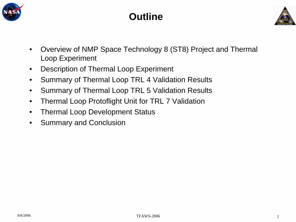
Summary of TRL 4 Validation Results• The Thermal Loop breadboard was tested in a laboratory environment.• The laboratory test demonstrated more than 1200 hours of LHP operation under a wide
range of operating conditions.• Test configuration
– Five configurations: horizontal, upside down, sideways, 45-degree tilt, vertical• Start-up
– More than 160 start-ups were performed. All were successful.– CC temperature: 0, 1 or both CCs were controlled at temperatures between 288K
and 313K – Heat load between 5W and 100W to only one of the evaporators– Heat load to both evaporators: 1W/1W, 5W/5W, 10W/10W, 5W/50W, 50W/50W, and
more– Temperatures of the two chillers: 243K to 293K, independent of each other
• Operation– The LHP operating temperature was controlled within ±0.5K of the desired set point
between 288K and 313K in all tests.– Demonstrated heat transport capability of more than 100W – Stable LHP operation at all times over the full range of heat loads and sink
temperatures– Demonstrated heat load sharing between the two evaporators
• Analytical Model– The model predicted all critical temperatures to within ± 5K during start-up and
operation

8/8/2006 TFAWS-2006 16
Summary of TRL 5 Validation Results• The MLHP breadboard was tested in a thermal vacuum environment.• The thermal vacuum test demonstrated more than 500 hours of LHP operation under a
wide range of operating conditions.• Start-up
– Fifty-one start-ups were performed. All were successful.– CC temperature: 0, 1 or both CCs were controlled at 258K, 273K, 283K, 288K, 293K,
298K, 303K, and 308K – Heat load between 5W and 50W to only one of the evaporators– Heat load to both evaporators: 5W/5W, 10W/10W, 5W/50W, 50W/5W, and more– Temperatures of the two condenser sinks: 203K/203K, 203K/243K, 273K/243K, and
more• Operation
– The LHP operating temperature was controlled within ±0.5K of the desired set point between 258K and 308K in all tests.
– Demonstrated heat transport capability of more than 100W – Stable LHP operation at all times over the full range of heat loads and sink
temperatures– Demonstrated heat load sharing between the two evaporators
• Analytical Model– The model predicted all critical temperatures to within ± 5K during start-up and
operation* This presentation will only highlight the TRL 5 validation results.

8/8/2006 TFAWS-2006 17
Thermal Loop TRL 5 Validation Test - Start-upNo control/293K, 50W/5W
• E1 was flooded prior to start-up – this is Condition 3. • E1 reached set point temperature first and started the loop with 7K superheat.
ST8 CETDP LHP TV Test 2-16-06
240
250
260
270
280
290
300
310
8:00 8:30 9:00 9:30Time (HH:MM)
Tem
pera
ture
(K)
0
10
20
30
40
50
60
70
80
90
100
110
120
130
140
150
Pow
er (W
)
E1 (1) E2 (3)
Vap Line (8)
CC1 (42)
CC2 (47)
E2 PowerLiq Line (36) E1 Power

Thermal Loop TRL 5 Validation Results –Comparison of Predictions with Test Data
230
240
250
260
270
280
290
300
310
8:00 8:15 8:30 8:45 9:00 9:15 9:300.0
10.0
20.0
30.0
40.0
50.0
60.0
70.0
80.0
Time
Tem
pera
ture
(K)
Pow
er (W
)
Date: 02/16/06 Sink = -103C/-103CHorizontal Configuration
E1 Power
Liq. Line @ Cond. Exit (TC2)
E1 Inlet Predict
Liq. Line Predict
E1 (TC2)E1 Predict
CC1 (TC42)CC2 Predict
CC2 (TC47)
E1 Inlet (TC38)
E2 PowerVapor (TC8)
• CC1/CC2 = NC/293K, C1/C2 sinks =173K/173K, E1/E2 power = 50W/5W, 5W/50W• Input data: superheat = 7K• The model predicts loop critical temperatures within ±5K.

8/8/2006 TFAWS-2006 19
Thermal Loop TRL 5 Validation Test - Start-up293K/293K, 0W/5W
• 2.5K superheat on E2 at start-up• E1 shared heat after loop started.
ST8 CETDP LHP TV Test 2-20-06
260
265
270
275
280
285
290
295
300
8:30 10:30Time (HH:MM)
Tem
pera
ture
(K)
0
5
10
15
20
25
30
35
40
Pow
er (W
)
E1 (1)
E2 (3) Vap Line (8)
CC1 (42) CC2(47)
E2 Power
Liq Line (36)

8/8/2006 TFAWS-2006 20
Thermal Loop TRL 5 Validation Test - Power Ramp Up
• CC1/CC2 = 308K/308K, C1/C2 sink = 123K/123K• E1/E2 Power: 10W/10W, 20W/20W, 30W/30W, 40W/40W, 50W/50W, 60W/60W, 40W/40W• Loop demonstrated more than 100W heat transport.• Loop operating temperature was controlled within ±1K of the 308K set point temperature. • The vapor line temperature was the same as the set point temperature.
ST8 CETDP LHP TV Test 2-15-06
290
295
300
305
310
315
320
14:30 15:00 15:30 16:00 16:30 17:00 17:30 18:00
Time (HH:MM)
Tem
pera
ture
(K)
0
10
20
30
40
50
60
70
80
90
100
110
120
Pow
er (W
)
E1 (2)
E2 (4)
Vap Line (8)
CC1 (42) CC2 (47)
E2 Power
CC1 Inlet (38)
E1 Power
CC 2 Inlet (39)

8/8/2006 TFAWS-2006 21
Thermal Loop TRL 5 Validation Test - Power Cycle• CC1/CC2= 293K/293K, C1/C2 sink = 173K/173K• E1/E2 power = 75W/0W, 50W/25W, 25W/50W, 0W/75W, 5W/50W, 50W/5W• The loop operating temperature was maintained within ±1K of the 298K set point
temperature.
ST8 CETDP LHP TV Test 2-28-06
275
280
285
290
295
300
305
11:45 12:15 12:45 13:15 13:45 14:15Time (HH:MM)
Tem
pera
ture
(K)
0
25
50
75
100
125
150
Pow
er (W
)
E1 (2)
E2 (3)
Vap Line (8) CC1 (42) CC2 (47)
E1 Power E2 Power
Liq Line (36)

8/8/2006 TFAWS-2006 22
Thermal Loop TRL 5 Validation Test - Flow Regulator Test• E1/E2 power = 30W/10W constant. CC1/CC2 = 293K/293K• C1/C2 sink = 223K/223K, 293K/223K, 298K/223K, 223K/223K, 223K/293K, 223K/298K
223K/223K, • Both sides of the flow regulator worked properly to stop vapor.
ST8 Prototype LHP TV Test 3/30/2006
250
255
260
265
270
275
280
285
290
295
300
9:30 10:30 11:30 12:30 13:30 14:30 15:30 16:30Time (HH:MM)
Tem
pera
ture
(K)
E1 (2)
CC1 (42)CC2 (47)
E1 = 30WE2 = 10W
Liq Line (36)
Cond 2 (34)
Cond 1 (21)

8/8/2006 TFAWS-2006 23
Thermal Loop TRL 5 Validation Test - Operation at 258K• C1/C2 sink = 203K/203K. No heat load to E1/E2.• CC1/CC2=293K/293K, 288K/288K, 283K/283K, 278K/278K, 273K/273K, 268K/268K, 263K/263K,
258K/258K• At 258K/258K, E1/E2 power = 10W/10W and 20W/20W• TECs enabled CC1/CC2 to control the loop saturation temperature below its natural
operating temperature.
ST8 CETDP LHP TV Test 3-27-06
230
235
240
245
250
255
260
265
270
275
280
285
290
295
9:30 10:00 10:30 11:00 11:30 12:00 12:30
Time (HH:MM)
Tem
pera
ture
(K)
0
10
20
30
40
50
60
70
80
90
100
Pow
er (W
)
E1 (2)E2 (3) Mass 1 (52)
CC1(42) CC2 (47)
E1 Power
Liq Line (36)
E2 Power

8/8/2006 TFAWS-2006 24
Thermal Loop TRL 5 Validation Test - Heat Load Sharing
• CC1/CC2 = 303K/NC, E2 power = 50W constant, C1/C2 sink = 203K/243K• E1 coolant flow rate = 0.15 gpm• E1 coolant temperature = 283K/288K/293K/298K/303K/308K• As coolant temperature reached 303K and 308K, E1 received heat from the coolant and
was in its normal operation (shared negative heat)
ST8 CETDP LHP TV Test 2-14-06
285
290
295
300
305
310
315
13:30 14:00 14:30 15:00 15:30 16:00 16:30
Time (HH:MM)
Tem
pera
ture
(K)
-15
-10
-5
0
5
10
15
20
25
Pow
er (W
)
E1 (2)
E2 (3)
Heat Shared by E1
CC2 (47)
CC1 (42)
E1 Sink (111)
8/8/2006 TFAWS-2006 25
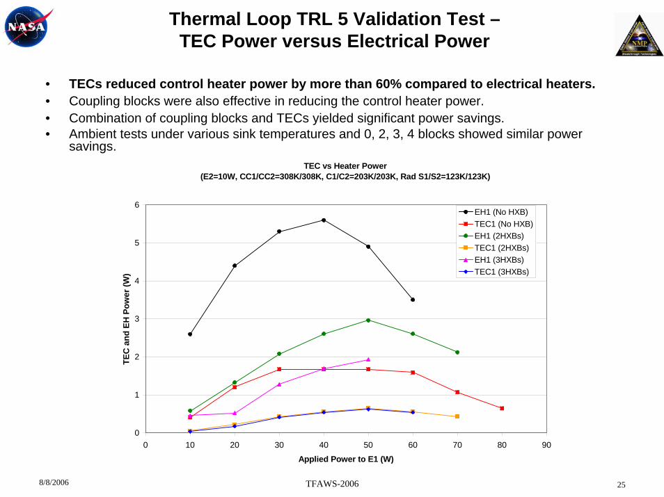
Thermal Loop TRL 5 Validation Test –TEC Power versus Electrical Power
• TECs reduced control heater power by more than 60% compared to electrical heaters.• Coupling blocks were also effective in reducing the control heater power.• Combination of coupling blocks and TECs yielded significant power savings.• Ambient tests under various sink temperatures and 0, 2, 3, 4 blocks showed similar power
savings.TEC vs Heater Power
(E2=10W, CC1/CC2=308K/308K, C1/C2=203K/203K, Rad S1/S2=123K/123K)
0
1
2
3
4
5
6
0 10 20 30 40 50 60 70 80 90
Applied Power to E1 (W)
TEC
and
EH
Pow
er (W
)
EH1 (No HXB)TEC1 (No HXB)EH1 (2HXBs)TEC1 (2HXBs)EH1 (3HXBs)TEC1 (3HXBs)
8/8/2006 TFAWS-2006 26
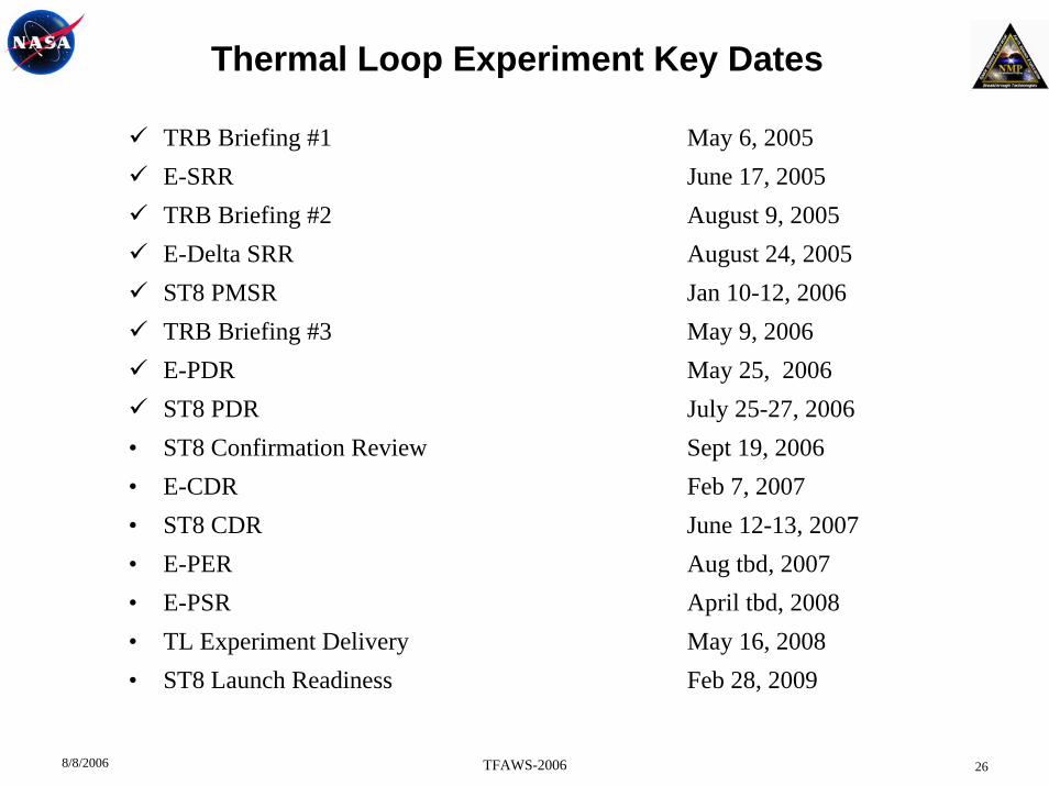
Thermal Loop Experiment Key Dates
TRB Briefing #1 May 6, 2005E-SRR June 17, 2005TRB Briefing #2 August 9, 2005E-Delta SRR August 24, 2005ST8 PMSR Jan 10-12, 2006TRB Briefing #3 May 9, 2006E-PDR May 25, 2006ST8 PDR July 25-27, 2006
• ST8 Confirmation Review Sept 19, 2006• E-CDR Feb 7, 2007• ST8 CDR June 12-13, 2007• E-PER Aug tbd, 2007• E-PSR April tbd, 2008• TL Experiment Delivery May 16, 2008• ST8 Launch Readiness Feb 28, 2009

8/8/2006 TFAWS-2006 27
Thermal Loop Experiment: MLHP Module for TRL 7 Validation(Top View)
Connector Bracket
S/C InterfaceBracket (4)
Mounting Frame
Radiator (2)
Radiator Supports
Liquid Line (Blue)
Vapor Line (Red)
+X
+Y
+Z

8/8/2006 TFAWS-2006 28
Thermal Loop Experiment: MLHP Module for TRL 7 Validation (view from S/C)
Instrument Simulator (2)(with Heaters & Thermostats)
Mounting Frame
Radiator (2)
S/C Interface Bracket (4)
Radiator Supports
Evaporator (2)
Compensation Chamber (2)
Vapor Line (Red)
Liquid Line (Blue)
Flow Regulator
Coupling Blocks
+X
+Y
+Z
MLI Support
8/8/2006 TFAWS-2006 29
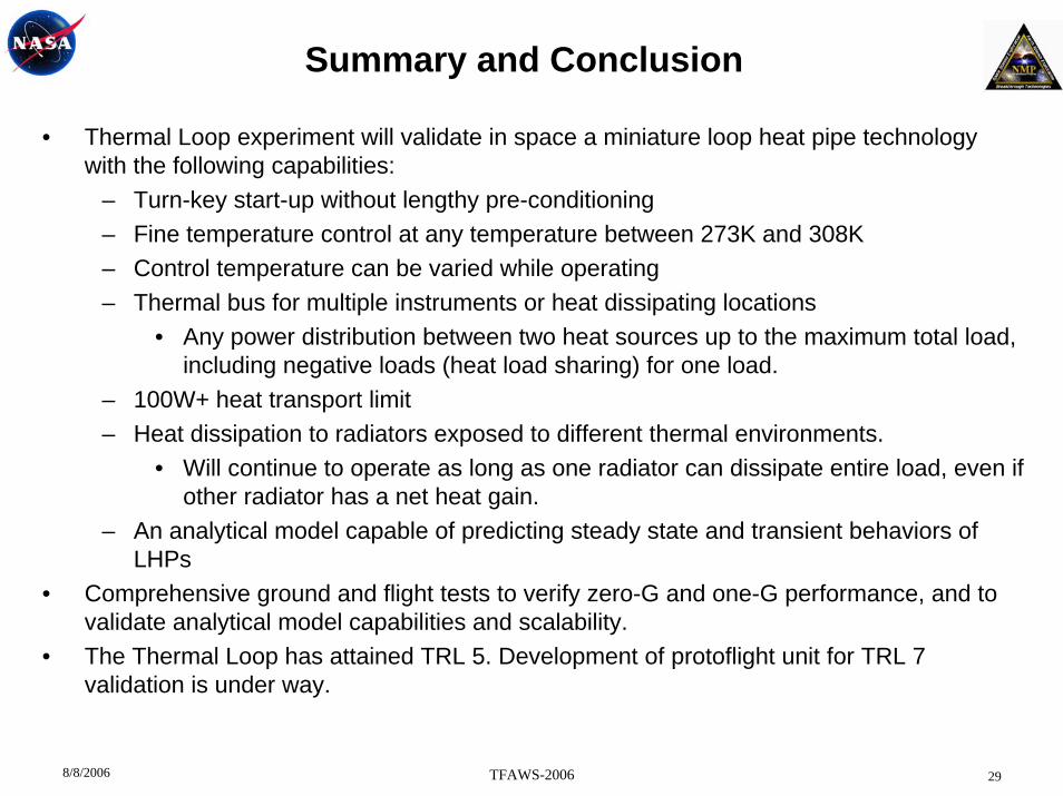
ValidationSummary and Conclusion
• Thermal Loop experiment will validate in space a miniature loop heat pipe technology with the following capabilities:
– Turn-key start-up without lengthy pre-conditioning– Fine temperature control at any temperature between 273K and 308K– Control temperature can be varied while operating– Thermal bus for multiple instruments or heat dissipating locations
• Any power distribution between two heat sources up to the maximum total load, including negative loads (heat load sharing) for one load.
– 100W+ heat transport limit– Heat dissipation to radiators exposed to different thermal environments.
• Will continue to operate as long as one radiator can dissipate entire load, even if other radiator has a net heat gain.
– An analytical model capable of predicting steady state and transient behaviors of LHPs
• Comprehensive ground and flight tests to verify zero-G and one-G performance, and to validate analytical model capabilities and scalability.
• The Thermal Loop has attained TRL 5. Development of protoflight unit for TRL 7 validation is under way.


![[Millennium Development Goals 1 and 3] By [Author Name ... · MILLENNIUM DEVELOPMENT GOALS 1 & 3 4 were termedas “Millennium Development Goals” and United Nations Millennium Declaration](https://img.dokumen.tips/doc/110x75/5edb6813ad6a402d66659cfd/millennium-development-goals-1-and-3-by-author-name-millennium-development.jpg)