Embed Size (px)
DESCRIPTION
Herramienta para recuperar discos duros.
Citation preview
The HDAT2 Cookbook
"How can I do…?"
Version 1.1
08.09.2010
Lubomir Cabla / CBL
http://www.hdat2.com/
Page i
Contents
CONTENTS ............................................................................................................................................................. 2
PREFACE ................................................................................................................................................................ 3
RUN THE PROGRAM ........................................................................................................................................... 4
OVERVIEW ................................................................................................................................................................ 4
CHANGE THE NATIVE SIZE (HPA, DCO) ...................................................................................................... 5
OVERVIEW ................................................................................................................................................................ 5 CREATE HIDDEN AREA HPA WITH SET MAX ADDRESS .......................................................................................... 5 CREATE HIDDEN AREA DCO ....................................................................................................................................... 9 REMOVE HIDDEN AREA HPA .................................................................................................................................... 15 REMOVE HIDDEN AREA HPA WITH SET MAX ADDRESS ....................................................................................... 15 REMOVE HIDDEN AREA DCO .................................................................................................................................... 20 AUTO REMOVE HIDDEN AREAS ................................................................................................................................... 20
LOCK THE DEVICE ........................................................................................................................................... 24
OVERVIEW .............................................................................................................................................................. 24
UNLOCK THE DEVICE ..................................................................................................................................... 26
OVERVIEW .............................................................................................................................................................. 26
ERASE THE DEVICE .......................................................................................................................................... 30
OVERVIEW .............................................................................................................................................................. 30 SECURITY ERASE THE DEVICE ..................................................................................................................................... 30 SCT WRITE SAME .................................................................................................................................................. 33
SEARCH THE DEVICE ...................................................................................................................................... 39
SEARCH FOR STRING ................................................................................................................................................. 39 SEARCH FOR EMPTY SECTOR ....................................................................................................................................... 43 SEARCH FOR NON-EMPTY SECTOR ............................................................................................................................... 44
FREQUENTLY ASKED QUESTIONS .............................................................................................................. 46
Page 2
Preface
This is the cookbook of program HDAT2 in pictures for beginners.
There should be the answers for questions "How can I do…?".
For a more detailed information see "User's Manual HDAT2".
I am sorry for my English.
Page 3
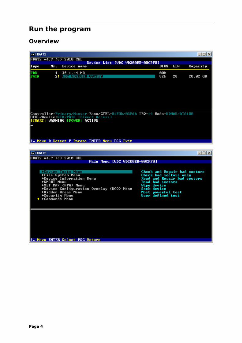
Run the program
Overview
Page 4
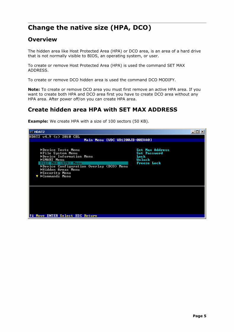
Change the native size (HPA, DCO)
Overview
The hidden area like Host Protected Area (HPA) or DCO area, is an area of a hard drive that is not normally visible to BIOS, an operating system, or user.
To create or remove Host Protected Area (HPA) is used the command SET MAX ADDRESS.
To create or remove DCO hidden area is used the command DCO MODIFY.
Note: To create or remove DCO area you must first remove an active HPA area. If you want to create both HPA and DCO area first you have to create DCO area without any HPA area. After power off/on you can create HPA area.
Create hidden area HPA with SET MAX ADDRESS
Example: We create HPA with a size of 100 sectors (50 KB).
Page 5
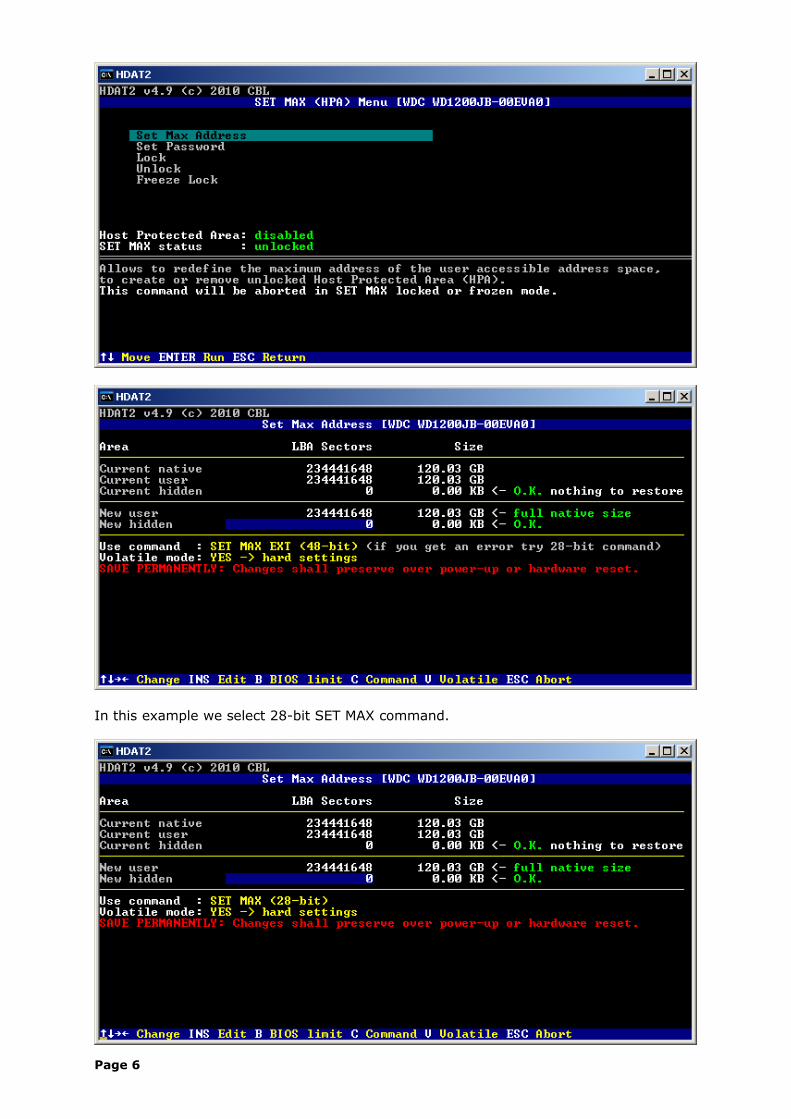
In this example we select 28-bit SET MAX command.
Page 6
Page 7
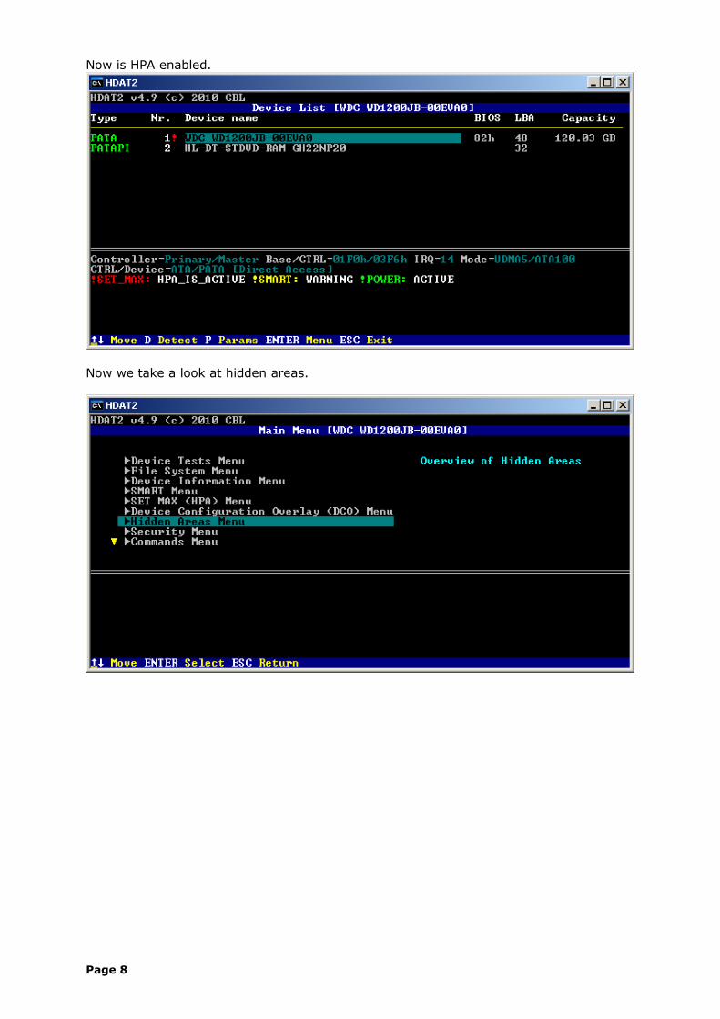
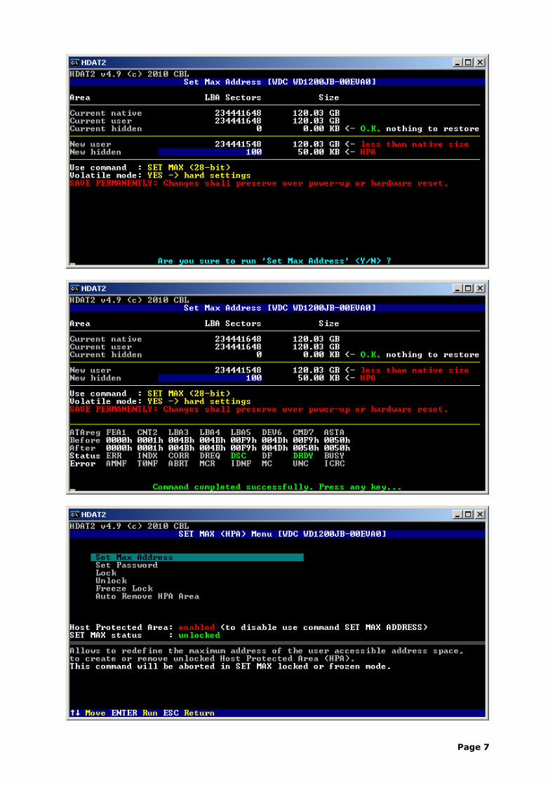
Now is HPA enabled.
Now we take a look at hidden areas.
Page 8
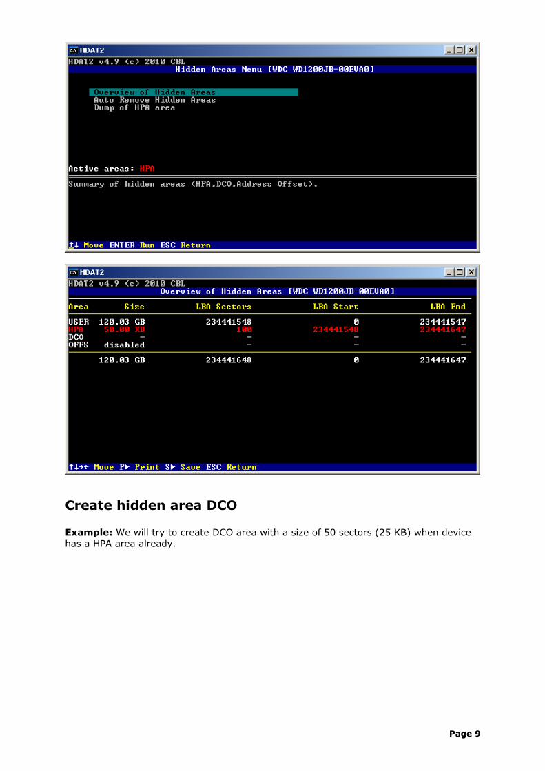
Create hidden area DCO
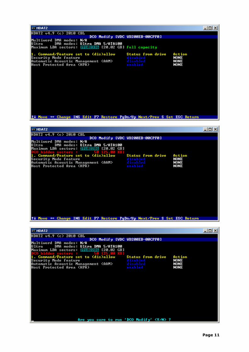
Example: We will try to create DCO area with a size of 50 sectors (25 KB) when device has a HPA area already.
Page 9
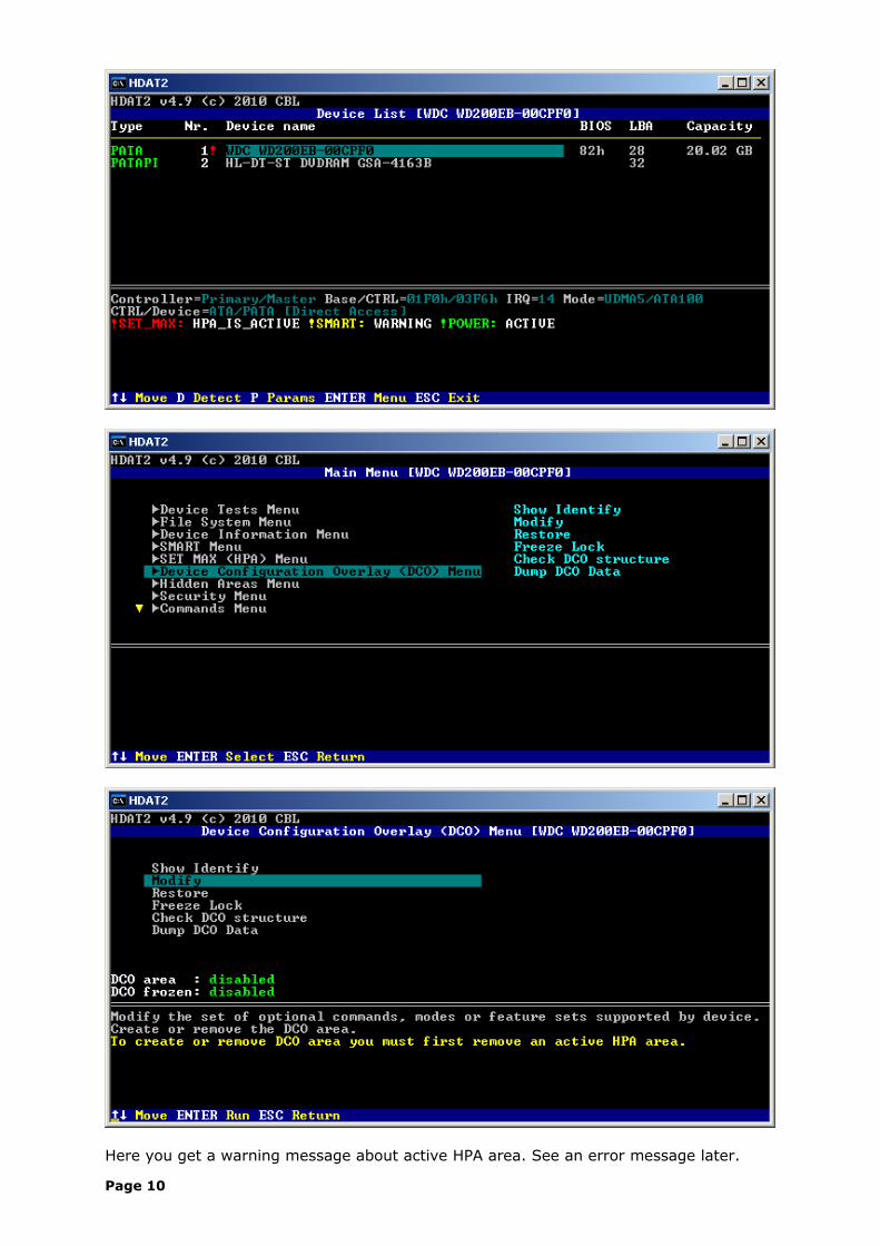
Here you get a warning message about active HPA area. See an error message later.
Page 10
Page 11
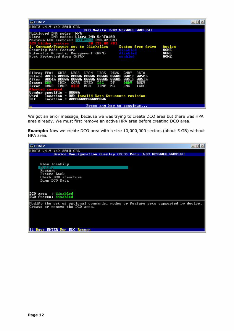
We got an error message, because we was trying to create DCO area but there was HPA area already. We must first remove an active HPA area before creating DCO area.
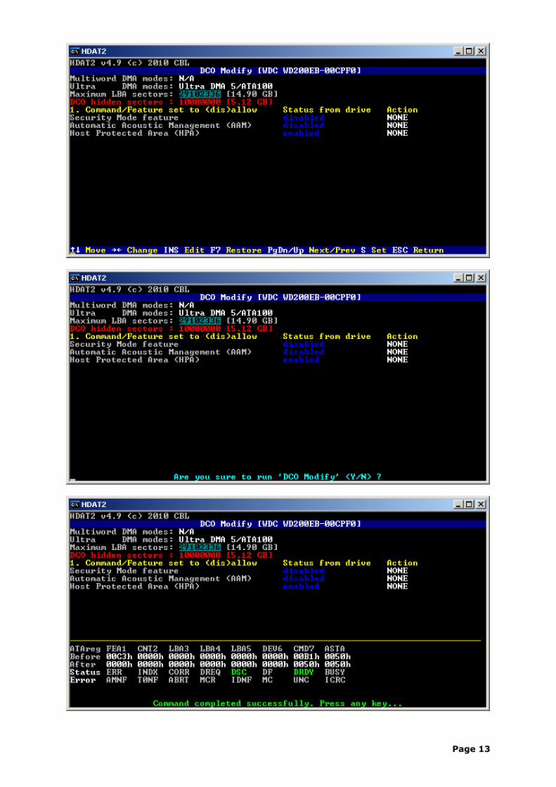
Example: Now we create DCO area with a size 10,000,000 sectors (about 5 GB) without HPA area.
Page 12
Page 13
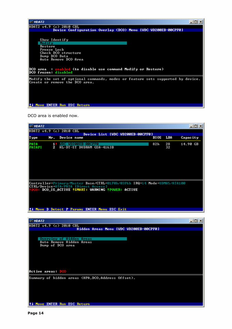
DCO area is enabled now.
Page 14
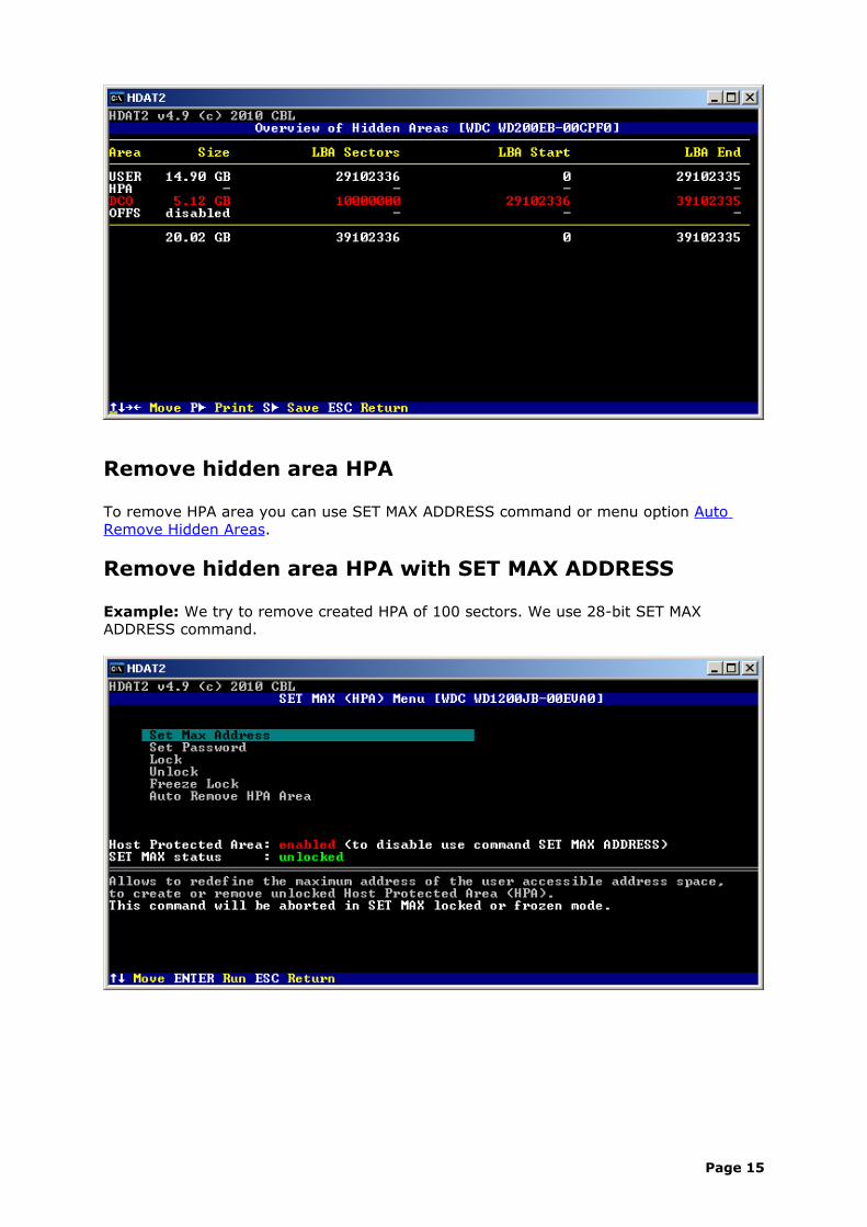
Remove hidden area HPA
To remove HPA area you can use SET MAX ADDRESS command or menu option Auto Remove Hidden Areas.
Remove hidden area HPA with SET MAX ADDRESS
Example: We try to remove created HPA of 100 sectors. We use 28-bit SET MAX ADDRESS command.
Page 15
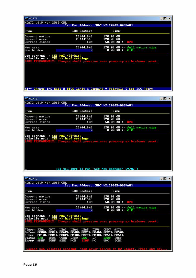
Page 16
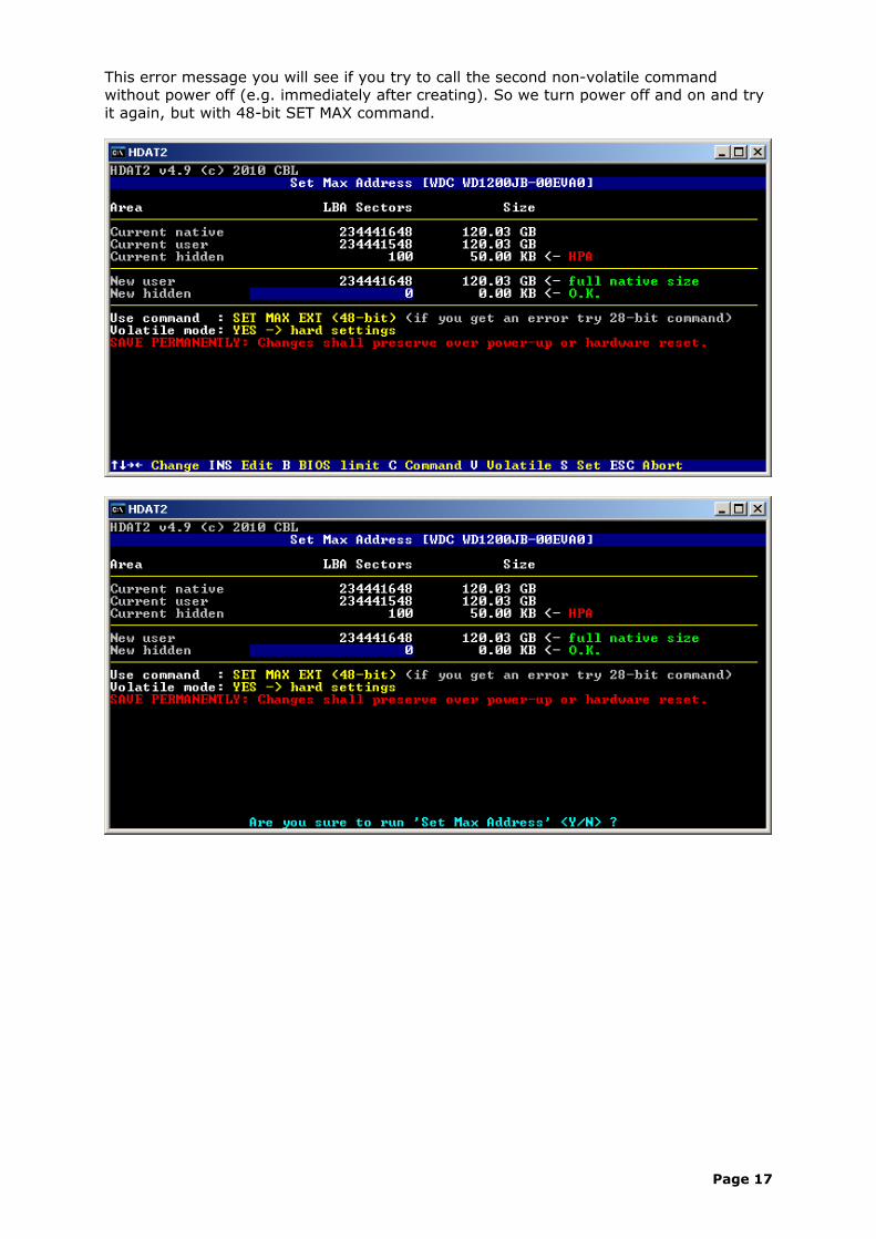
This error message you will see if you try to call the second non-volatile command without power off (e.g. immediately after creating). So we turn power off and on and try it again, but with 48-bit SET MAX command.
Page 17
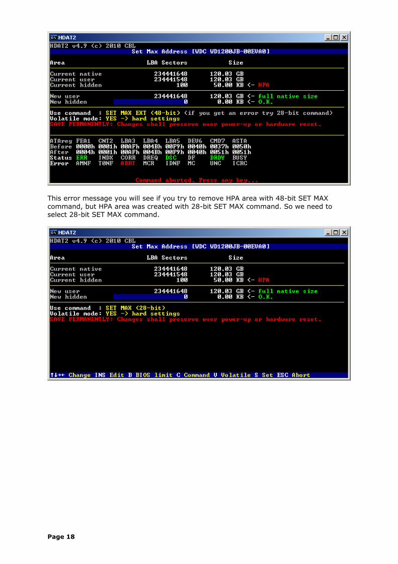
This error message you will see if you try to remove HPA area with 48-bit SET MAX command, but HPA area was created with 28-bit SET MAX command. So we need to select 28-bit SET MAX command.
Page 18
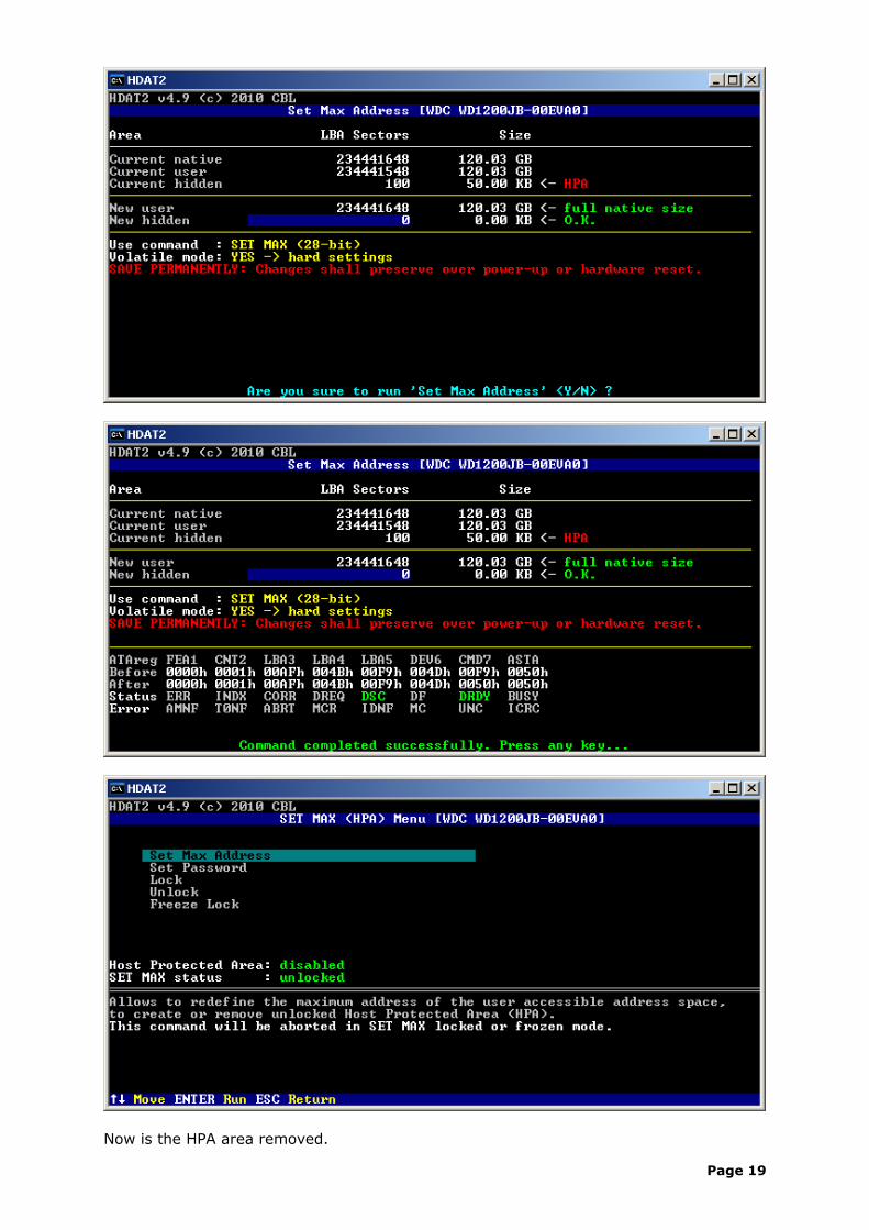
Now is the HPA area removed.
Page 19
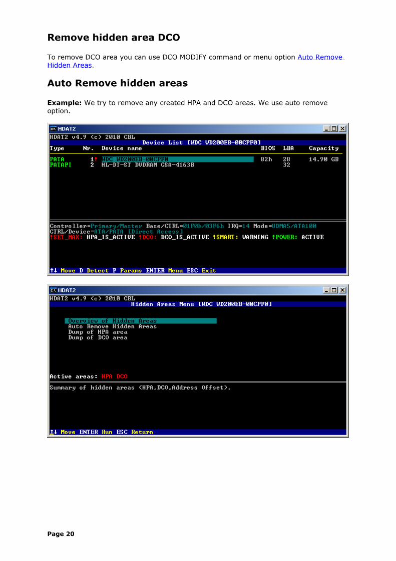
Remove hidden area DCO
To remove DCO area you can use DCO MODIFY command or menu option Auto Remove Hidden Areas.
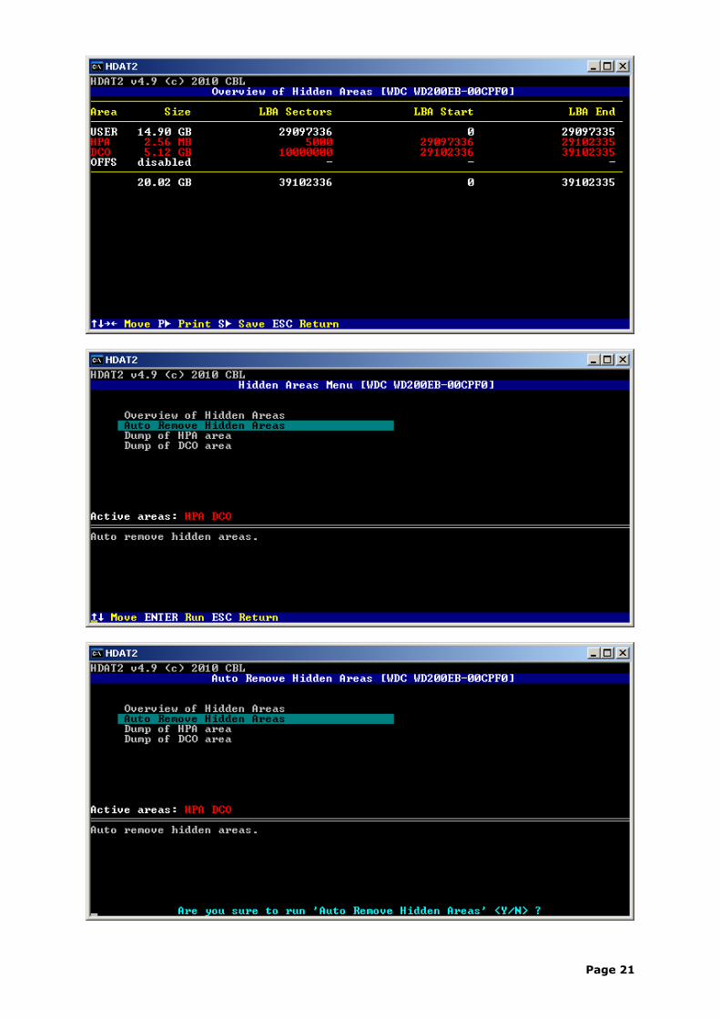
Auto Remove hidden areas
Example: We try to remove any created HPA and DCO areas. We use auto remove option.
Page 20
Page 21
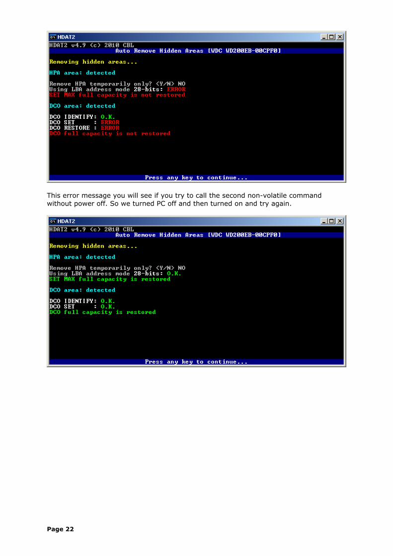
This error message you will see if you try to call the second non-volatile command without power off. So we turned PC off and then turned on and try again.
Page 22
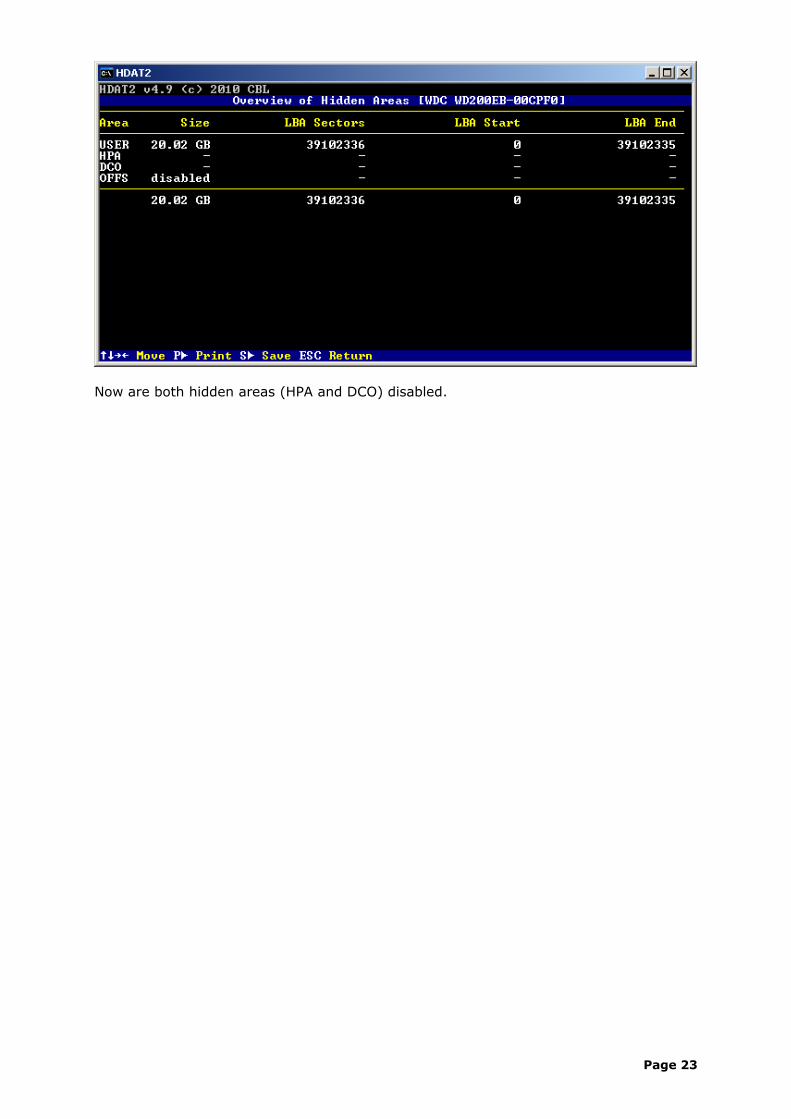
Now are both hidden areas (HPA and DCO) disabled.
Page 23
Lock the device
Overview
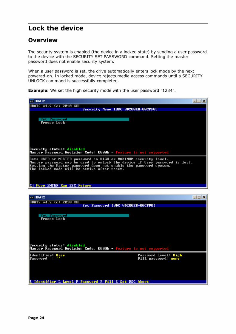
The security system is enabled (the device in a locked state) by sending a user password to the device with the SECURITY SET PASSWORD command. Setting the master password does not enable security system.
When a user password is set, the drive automatically enters lock mode by the next powered-on. In locked mode, device rejects media access commands until a SECURITY UNLOCK command is successfully completed.
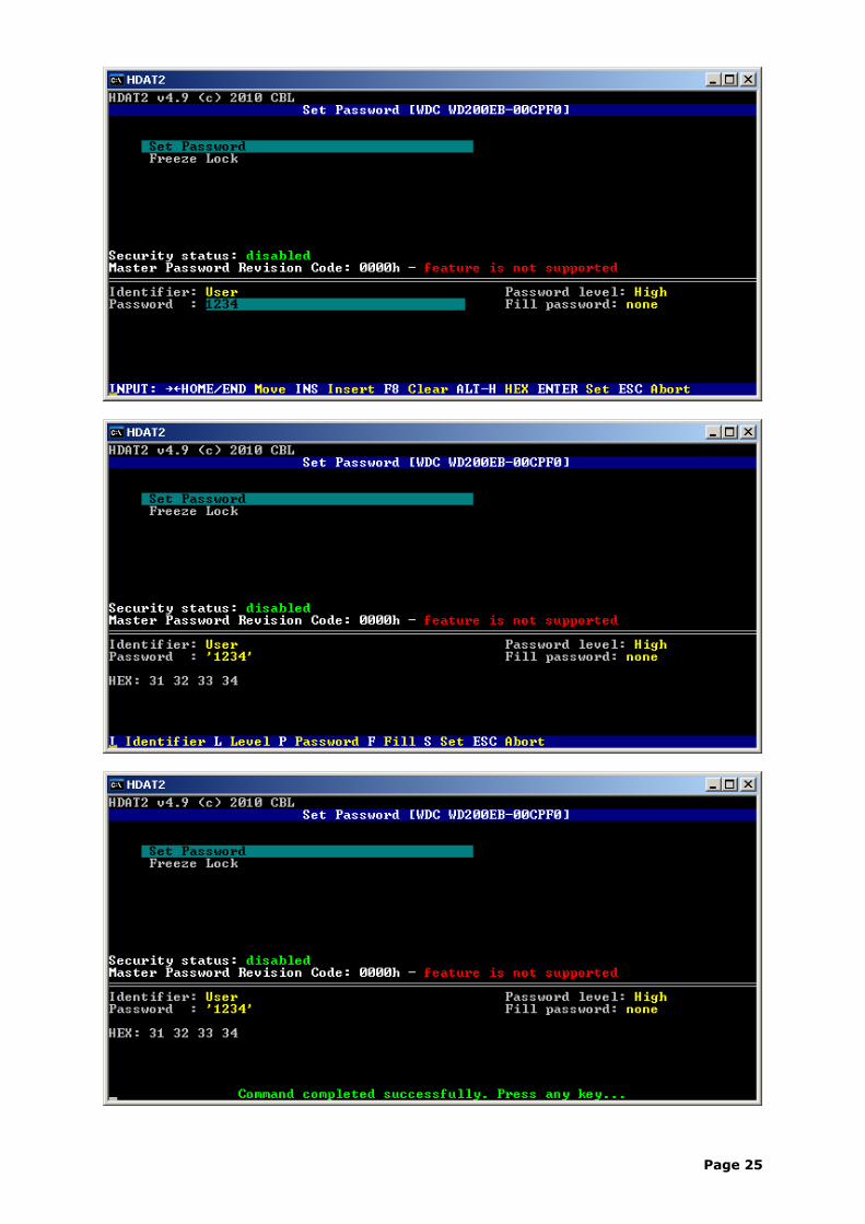
Example: We set the high security mode with the user password "1234".
Page 24
Page 25
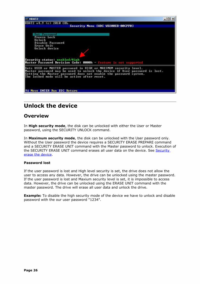
Unlock the device
Overview
In High security mode, the disk can be unlocked with either the User or Master password, using the SECURITY UNLOCK command.
In Maximum security mode, the disk can be unlocked with the User password only.Without the User password the device requires a SECURITY ERASE PREPARE command and a SECURITY ERASE UNIT command with the Master password to unlock. Execution of the SECURITY ERASE UNIT command erases all user data on the device. See Security erase the device.
Password lost
If the user password is lost and High level security is set, the drive does not allow the user to access any data. However, the drive can be unlocked using the master password.If the user password is lost and Maxium security level is set, it is impossible to access data. However, the drive can be unlocked using the ERASE UNIT command with the master password. The drive will erase all user data and unlock the drive.
Example: To disable the high security mode of the device we have to unlock and disable password with the our user password "1234".
Page 26
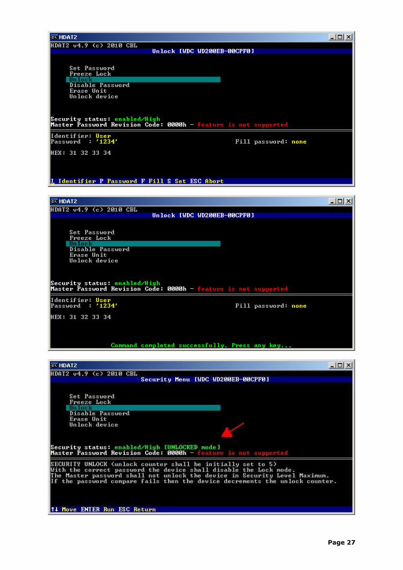
Page 27
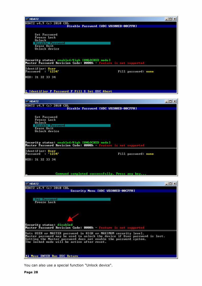
You can also use a special function "Unlock device".
Page 28
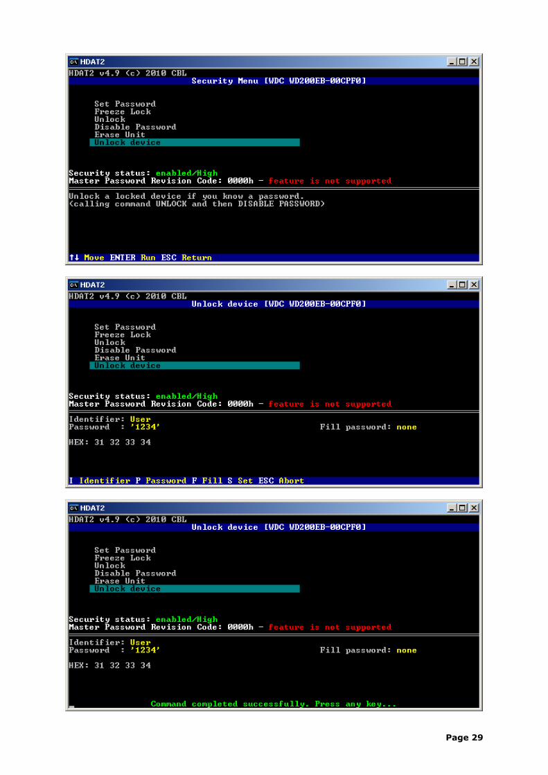
Page 29

Erase the device
Overview
Erase (wipe) does not mean delete or format. Data erasure is a method of software based overwriting. It uses a application to write patterns of data (like 00h or FFh) onto each of a hard drive's sectors on all areas of a hard drive.
To erase device you can use SECURITY ERASE UNIT command in Security Menu or, when supported, SCT Write Same command in SMART Menu.
Disk overwriting programs that cannot access the entire hard drive, including hidden areas like the Host Protected Area (HPA), Device Configuration Overlay (DCO), and remapped sectors, perform an incomplete erasure, leaving some of the data intact.
To use security erase command you should first set any password – we use password "1234".
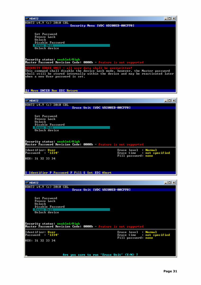
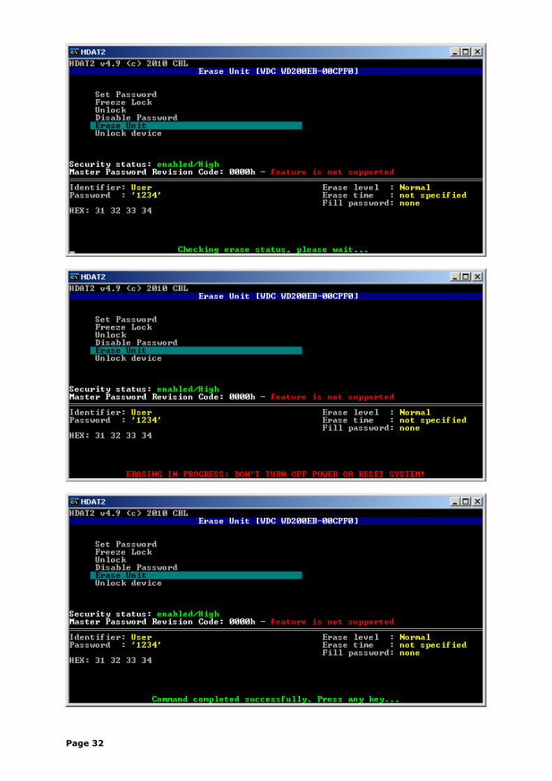
Security erase the device
In Enhanced Erase mode, all previously written user data shall be overwritten, including sectors that are no longer in use due to reallocation.
SECURITY ERASE UNIT allow erase HPA (Host Protected Area) or DCO (Device Configuration Overlay) areas, if any, as well. But don't remove these areas.
Also in High security mode the SECURITY ERASE UNIT command can be used with either the User or Master password.
Page 30
Page 31
Page 32
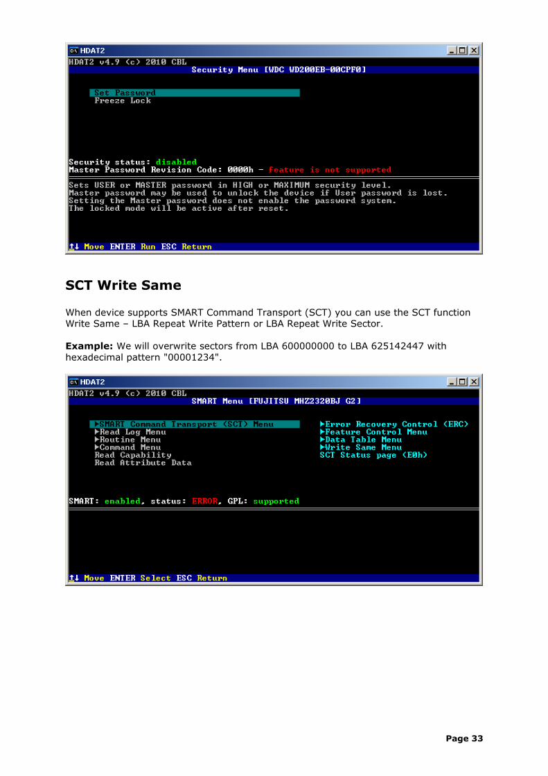
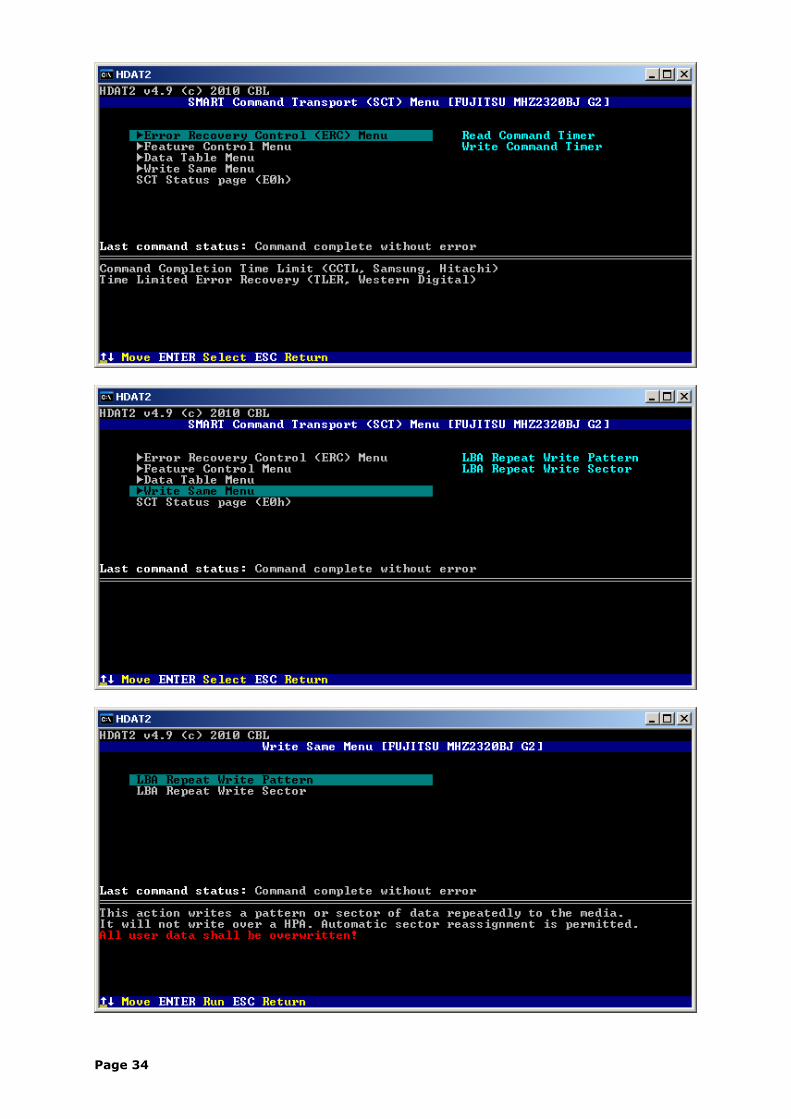
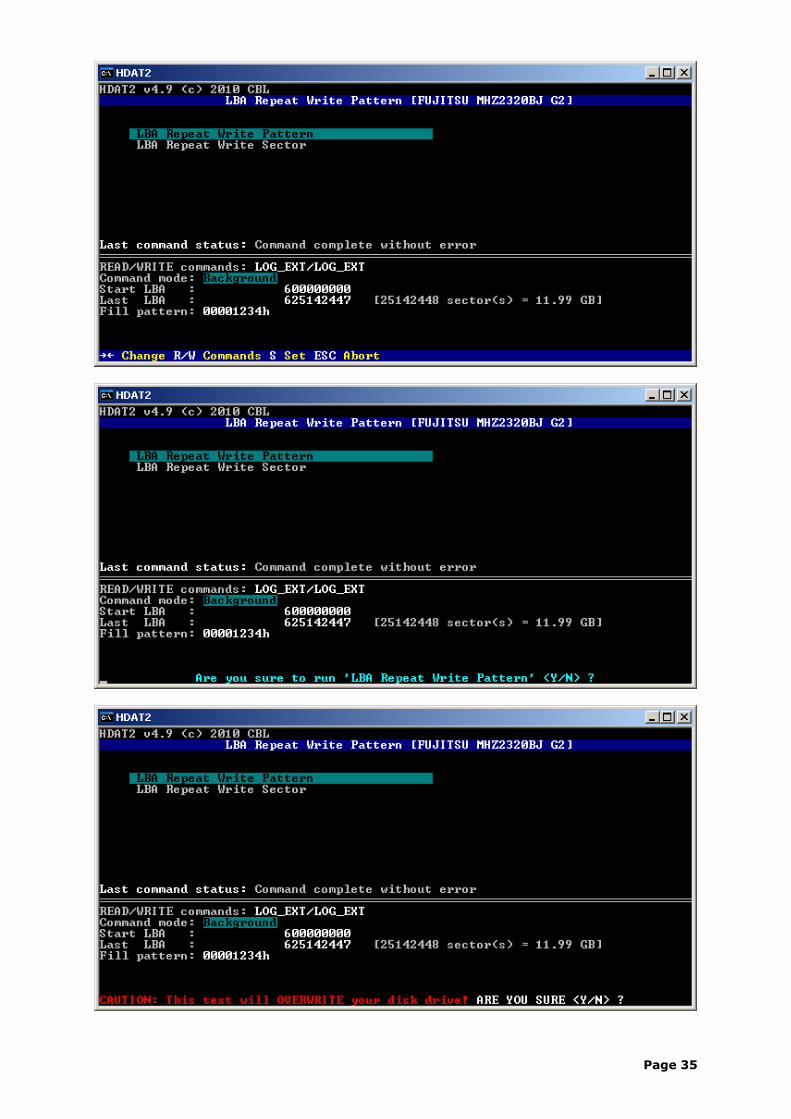
SCT Write Same
When device supports SMART Command Transport (SCT) you can use the SCT function Write Same – LBA Repeat Write Pattern or LBA Repeat Write Sector.
Example: We will overwrite sectors from LBA 600000000 to LBA 625142447 with hexadecimal pattern "00001234".
Page 33
Page 34
Page 35
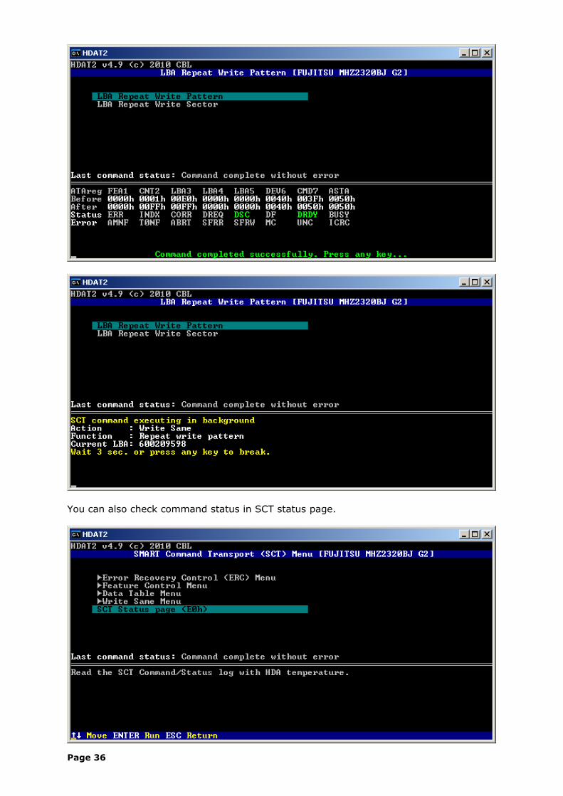
You can also check command status in SCT status page.
Page 36
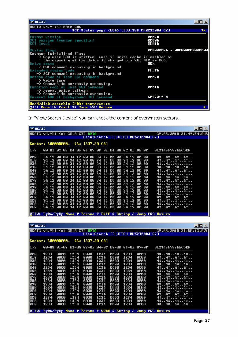
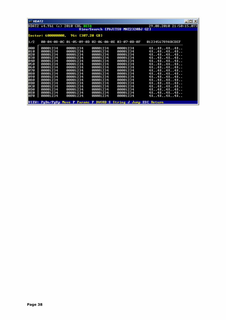
In "View/Search Device" you can check the content of overwritten sectors.
Page 37
Page 38
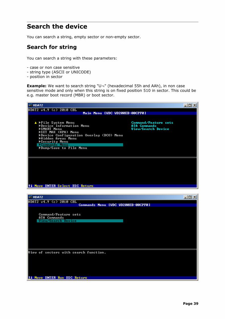
Search the device
You can search a string, empty sector or non-empty sector.
Search for string
You can search a string with these parameters:
- case or non case sensitive- string type (ASCII or UNICODE)- position in sector
Example: We want to search string "U¬" (hexadecimal 55h and AAh), in non case sensitive mode and only when this string is on fixed position 510 in sector. This could be e.g. master boot record (MBR) or boot sector.
Page 39
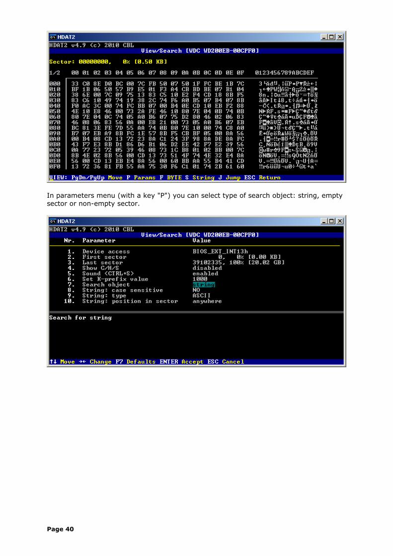
In parameters menu (with a key "P") you can select type of search object: string, empty sector or non-empty sector.
Page 40
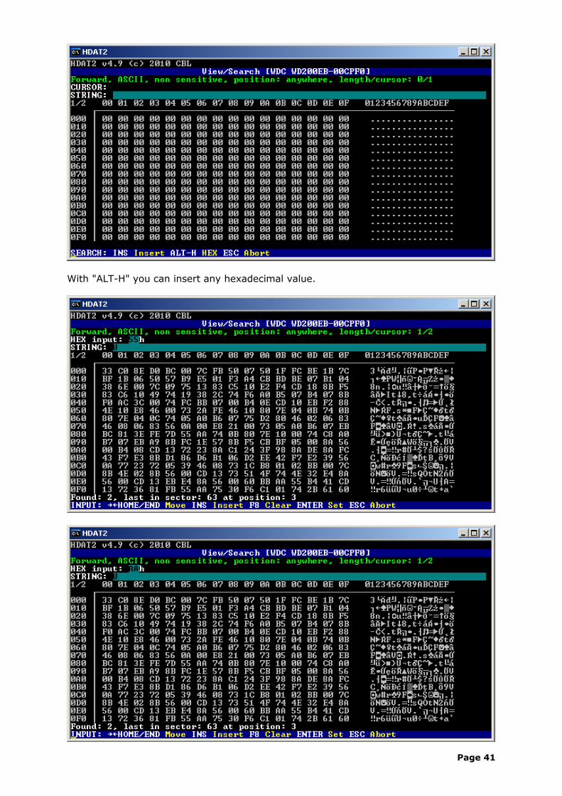
With "ALT-H" you can insert any hexadecimal value.
Page 41
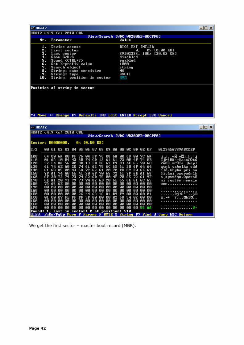
We get the first sector – master boot record (MBR).
Page 42
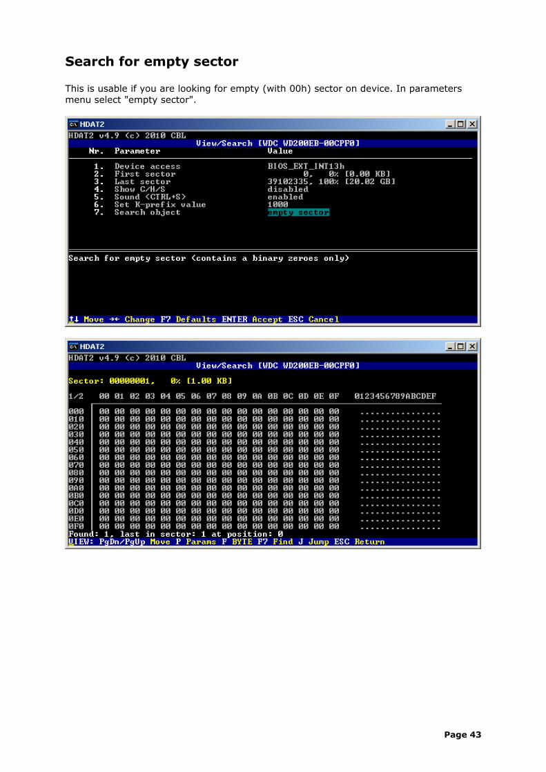
Search for empty sector
This is usable if you are looking for empty (with 00h) sector on device. In parameters menu select "empty sector".
Page 43
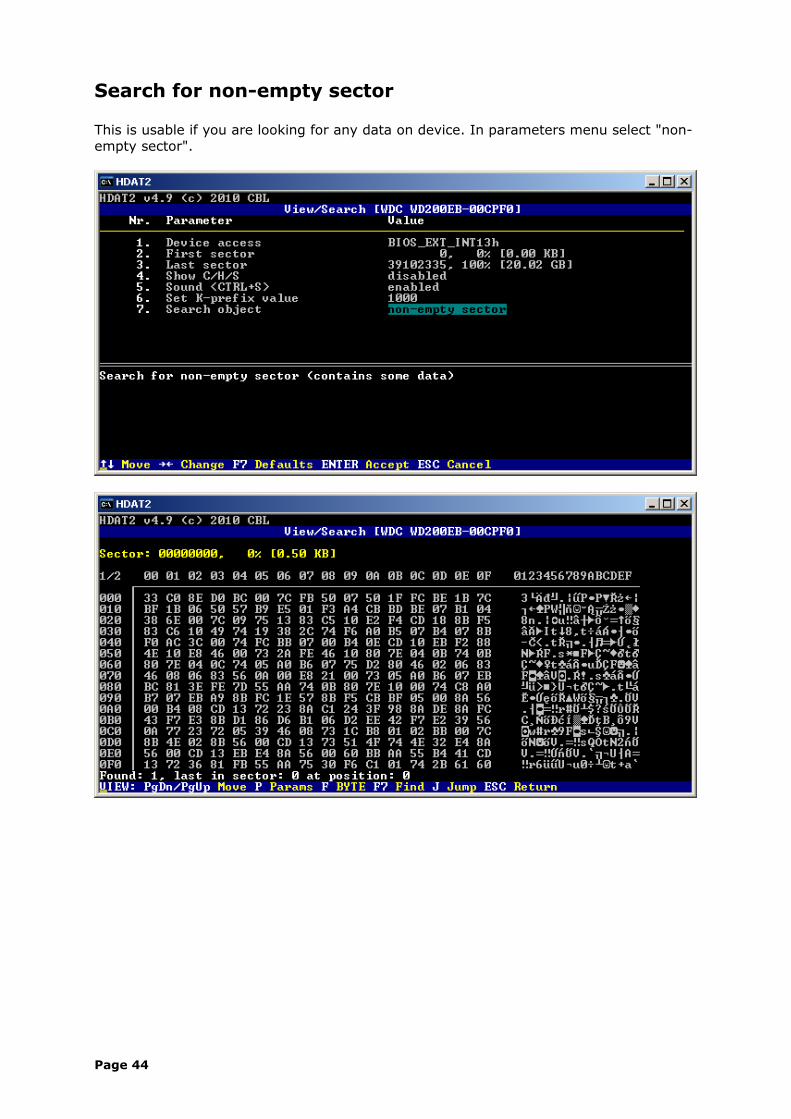
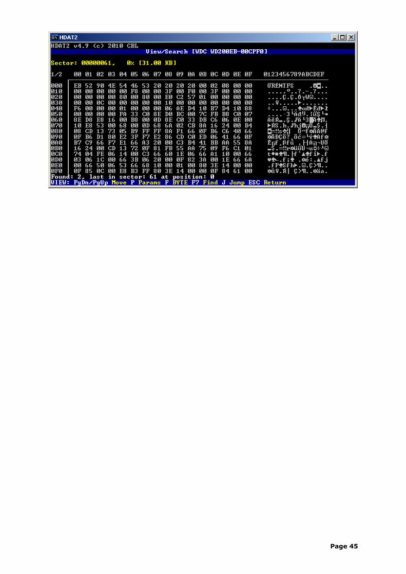
Search for non-empty sector
This is usable if you are looking for any data on device. In parameters menu select "non-empty sector".
Page 44
Page 45
Frequently Asked Questions
1. I received a 40 GB drive in replacement for a 20 GB model in PC. The drive is reported as 20 GB capacity. How can i get full capacity ?
2. How to bypass a Security and/or DCO frozen state ?3. Can i remove non-existent bad sectors from the file table FAT ?4. Connecting ATA/IDE Hard Drives5. What are the differences between master/slave and cable select ?6. Host Protected Area (HPA) vs. 28/48-bit LBA mode7. Change of DCO Modify item is always aborted (abort command)8. What is Spread Spectrum Clocking (SSC) ?9. SATA NCQ / eSATA / xSATA10.Can I cut down size of hard drive ?11.How can I determine supported media format of CD/DVD drive ?12.Portable computer with Windows Vista has problem with power
consumption.13.Host Protected Area (HPA) from BIOS.14.The Hidden Protected Area (hidden partition).15. I cannot remove Host Protected Area (HPA) on Dell notebook (Media
Direct HPA).16. I cannot read SMART for USB/Firewire hard drives.17.Western Digital WD5000KS doesn't spin-up (firmware bug).18.How to non-destructively convert dynamic disks to basic disks.19.Hard disk doesn't spin up - PUIS (Power Up In Standby).20.Windows support for logical units larger than 2 TB.21.GUID partition table (GPT) disks.
Q1: I received a 40 GB drive in replacement for a 20 GB model in PC. The drive is reported as 20 GB capacity. How can i get full capacity ? A1: If you see in 'Device List' menu at your disk drive a notice '!SET MAX: HPA IS ACTIVE', use 1. method, otherwise use 2. method.In program HDAT2 select your disk drive and press Enter to show 'Main Menu'.
1. method:
In 'Device List' menu at your disk drive you see notice '!SET MAX: HPA IS ACTIVE'.Select 'SET MAX (HPA) Menu', then select 'Set Max Address' and press Enter. By default is set so called native size of disk drive disku and you can just press a key 'S' to setup original capacity of hard drive and remove HPA area.If the command is aborted, try change 'LBA mode' from 28 to 48 or vice versa (if disk supports 48-bit LBA mode).
2. method:
Select 'Device Configuration Menu', then select 'Restore' and press Enter. If you don't see any error message, in 'Device List' menu press a key 'D' to make new detection of devices or simple make restart of PC's and check capacity of your hard drive.If you see any error message or in 'Device List' menu at your disk you see a notice '!DCO: FROZEN', then it is possible that BIOS was sent a command DCO Freeze and all subsequent DCO commands will be aborted now. How to try bypass this state see answer nr. 2.
Q2: How to bypass a Security and/or DCO frozen state ? A2: Turn off PC, remove ribbon (data) cable from this hard drive (not the power cable), turn on PC and after boot from floppy you can connect ribbon (data) cable back to hard drive and start up HDAT2. Don't worry - program can detect this device.
Page 46
Notice: this is valid only for PATA drivers, not for SATA drivers.If you have SATA drive in Security and/or DCO frozen state, simple solution is connect this drive to PC with BIOS which doesn't set security mode.
Q3: Can i remove non-existent bad sectors from the file table FAT ? A3: Yes, with file-system version program HDAT2FS or HDAT2 you can test FAT12/16/32.
select your drive and press Enter to run Menu select 'File Level Tests Menu' and press Enter select 'Read File System from MBR' and press Enter for item 'All' press 'C' to check detected items goto to 'Table' item and 2-times press Enter to run Utility menu press 'T' to setup test for file table FAT if you want to update file table press 'W' for update press Enter to runThis procedure will first compare both FAT copies and second tests all FAT entries for bad sectors. If program will find 'bad sector' entry, then all sectors in this cluster will be tested. If all these sectors are not bad program will remove this record of bad sectors.
Q4: Connecting ATA/IDE Hard Drives A4: ATA/IDE devices use a ribbon cable to connect to each other. Ribbon cables have all of the wires laid flat next to each other instead of bunched or wrapped together in a bundle. IDE ribbon cables have either 40 or 80 wires. There is a connector at each end of the cable and another one about two-thirds of the distance from the motherboard connector. This cable cannot exceed 18 inches in total length (12 inches from first to second connector, and six inches from second to third) to maintain signal integrity.40-wire Cables
On the slower older 40-wire ATA cables, the Slave device, usually a CD-ROM or CD-ROM recorder/burner still goes on the END, but you need to set the jumpers as Slave. This is true even if you don't have a hard drive in the Master position. The Master for 40-wire cables goes on the the Middle connector.
If you want to use the cable select with the older drive on a 40-wire cable, you'll have to consult the maker of the drive for the instructions.
80-wire Cables
On the ATA66/100/133 standard 80-wire cable, the Master hard drive or your boot hard drive goes on the END of the cable. This is true whether or not you use the Master/Slave style or the Cable Select style.
The 40-pin 80-conductor cable is orientation specific. The cable connectors are color-coded: blue for the host connector, black and gray for the primary and secondary disk drives. The blue connector should be installed into the Primary IDE connector.
The blue connector attaches to the motherboard.The black connector attaches to the primary, or master, drive.The gray connector attaches to the secondary, or slave, drive.
Along one side of the cable is a stripe. This stripe tells you that the wire on that side is attached to Pin 1 of each connector. Wire 20 is not connected to anything. In fact, there is no pin at that position. This position is used to ensure that the cable is attached to the drive in the correct position. Another way that manufacturers use to make sure that the cable is not reversed is by using a cable key. The cable key is a small plastic square on top of the connector on the ribbon cable that fits into a notch on the connector of the device. This allows the cable to attach in only one position.
Q5: What are the differences between master/slave and cable select ?
Page 47
A5: Two different protocols can be used for jumpering ATA devices, including hard disk drives. One is the master-slave relationship. With this protocol, one device is jumpered as master and the other is jumpered as slave. The second protocol is cable select. With this protocol, both devices are jumpered as cable select and their position on the cable dictates which is the master and which is the slave. The end device is master while the device on the middle of the cable is slave. You can use either of these protocols but you cannot mix them on the same data cable.Computers that use cable-select determine the master and slave drives by selecting or deselecting pin 28, CSEL, on the interface bus. Master and slave drives are determined by their physical position on the cable.
Configuration Using Cable Select
Cable Select is defined in the ATA-2 and ATA-3 specifications and is part of the ATA PnP standard and Microsoft's PC97 standard.
The standard 40-wire ATA ribbon cable and the 80-wire cable give different drive behavior when using Cable Select. If using the standard 40-wire cable, the Master goes in the middle connector and the Slave goes in the end connector. If using the 80-wire cable, attach the blue end connector to the system board or host controller, the gray middle connector to the Slave, and the black end connector to the Master.
All newer ATA hard drives can be jumpered as Cable Select (CS or CSEL). This is an alternate way to indicate which drive is master and which drive is slave (instead of jumpering one drive as master and one drive as slave). Cable Select jumpering requires a special IDE cable with wire 28 not connected to one of the drive connectors, which would configure the drive attached to that connector as the slave drive.
In order to use Cable Select jumpering, several conditions must be met. Both drives on a channel must support CSEL, both drives must be jumpered as CSEL, a CSEL cable must be used, and the host interface connector must support CSEL. For the host interface to support Cable Select, wire 28 must be grounded.
Although the Cable Select specification may simplify things in the future, there will probably be lots of confusion, especially on legacy systems, as this starts to be introduced. One problem will be in selecting the correct cable. Supposedly, the cables used for Cable Select will be clearly marked, with each connector labeled as Device 0 (or Master) or Device 1 (or Slave). If not clearly marked, it may not be easy to identify a CSEL cable visually. wire 28 can be checked for continuity.
A Cable Select cable can be constructed in various ways. Pin 28 may be non connected to the connector at the end of the cable or to the connector in the middle of the cable. Another design would have the host interface connector in the middle and the two drives would plug into each end of the cable, with the connector at one of the ends not connected to pin 28.
If both drives are set for CSEL and the host interface supports CSEL, but a regular cable is used, both drives will be seen as master.
A Cable Select cable can be used with master/slave drive jumpering.
Another problem will be with host interfaces on legacy motherboards and controller cards. If pin 28 is not grounded on the host interface, drives connected to either connector on the CSEL cable will be seen as slave. It will be common to find that pin 28 is open or high on many older IDE interfaces. This can be checked with a voltmeter.
Q6: Host Protected Area (HPA) vs. 28/48-bit LBA mode
Page 48
A6: There is a problem of incompatibility on some hard drives (e.g. Seagate and/or in an external Maxtor One Touch) when you are using 48-bit command for removing Host Protected Area (HPA) created with 28-bit command.48-bit command cannot remove HPA created with 28-bit command and vice-versa. Following solution is for disk supports 48-bit LBA mode only and if you have HPA greater than 127 GB.Notice:
"Some vendor-specific external drive enclosures (Maxtor) are known to use HPA to limit the capacity of unknown replacement hard drives installed into the enclosure. When this occurs, the drive may appear to be limited in size (e.g. 128 GB). In this case, one must use software utilities that use READ NATIVE MAX ADDRESS and SET MAX ADDRESS to change the drive's reported size back to its native size."
Solution:
1. Power-on PC, boot and start HDAT2.2. In 'SET MAX (HPA) Menu' select 'Set Max Address'. Change 'LBA mode' from 48 to 28-bit LBA mode and press 'S' key to set maximal address for 28-bit LBA mode (127 GB).3. Power-off PC (Important !), power-on PC, boot and start HDAT2.4. In 'SET MAX (HPA) Menu' select 'Set Max Address'. Leave the selected 48-bit 'LBA mode' (or change 'LBA mode' from 28 to 48-bit LBA mode) and then press 'S' key to set maximal address for 48-bit LBA mode.5. After restart you should get the full (native) capacity of hard drive.
Q7: Change of DCO Modify item is always aborted (abort command) A7: Some hard drives (Maxtor) allow to modify DCO always, the other hard drives (Seagate) allow to modify DCO one times only.Example of the restrictions on changing of bits:
If a user attempts to change maximum LBA address (SET or RESTORE) after establishing a protected area with SET MAX address, the device will abort that command.
If the user attempts to disable Security feature when the device is enabled and the Security feature is set, the device will abort that command.
If you always got an error message (aborted command) when you want to change any item in DCO Modify menu, you should first run a 'Restore' item to restore default settings and then you can go to Modify menu.
Q8: What is Spread Spectrum Clocking (SSC) ?
A8: Spread Spectrum Clocking is a way to lower electromagnetic interference or EMI. This is important for storage solutions that are required to pass FCC and other agency certifications. Today, some Serial ATA disk drives implement SSC, some allow you to turn this feature on/off, and some do not implement SSC; it is anticipated that all will implement this feature in the near future.The technique of modulating the operating frequency of a circuit slightly to spread its radiated emissions over a range of frequencies rather than just one tone. This reduction in the maximum emission for a given frequency helps meet FCC requirements.
Newer Serial ATA (3Gbps SATA) interface disc drives may employ a standard technology called Spread Spectrum Clocking (SSC) which helps to reduce electronic emissions (EMI) in large, multi-drive systems. Single drive environments do not need SSC to meet EMI requirements.
3Gbps means doubled interface speeds, which also means greater signal noise and electromagnetic emissions. As in the processor settings in many motherboards' BIOSes, spread spectrum clocking can reduce emissions to meet regulations.
Page 49
In a single-drive environment, it's not necessary, but when you've got two or more drives, and they're all running at 3Gbps, that's when you've got a lot of electrical noise going on, and the spread spectrum feature is recommended. This is more for safety than reducing data errors, which most drives' ECC code will correct automatically.
A small number of SATA host products do not support this SSC standard feature. Similarly, RAID controllers may need to enable SSC on drive configurations with SSC disabled by default to reduce EMI.
Disable SSC: Host products that do not support SSC cannot detect the presence of the disc drive. Therefore, in order to disable SSC the drive must be attached to another host platform that does support SSC so that the feature can be disabled. Once SSC is turned off, the drive can be returned to the original host system.
Enable SSC: If the drive has SSC turned off by default and SSC is required for a large multi-drive environment, the target system is usually supported by the SSC software. RAID controllers, however, can pose a barrier to communicating with the SATA at the low hardware level required to make the SSC change. If your RAID controller is not supported then a more standard SATA system may be needed to toggle SSC on the drive. Once SSC is turned on, the drive can be returned to the original RAID controller.
There are many accounts on the Internet about problems arising from HBAs (Host Bus Adapter) not supporting SSC as required. Disk drive vendors that tried turning on SSC have had to provide consumers special programs or jumpers to turn SSC off so they will work in non-compliant systems.
IntelAppleApple discussionsSeriTek controller/Hitachi hard disksSeagateWestern DigitalHitachi
Due to this problem, users believe that SATA 3Gb/s HDD's are not compatible with SATA 1.5Gb/s controllers. This is inaccurate as the technology is definitely backwards compatible.
Q9: SATA NCQ / eSATA / xSATA A9: NCQ: NCQ (Native Command Queuing) debuted in many 1.5Gbps drives as a refinement of earlier CQ schemes used in SCSI drives. When a supporting controller sends NCQ-enabled commands to a drive, the drive will intelligently prioritize up to 32 of those commands before performing the reads/writes. Because the controller triggers CQ, the user can enable/disable it in the OS, as from Windows XP's Device Manager. That applications that take advantage of the multithreading features of dual-core and/or Hyper-Threaded processors should complement NCQ for faster throughput.Explains Native Command Queing (NCQ) SeagateeSATA: More of a cable and connector redesign than a fundamental change, eSATA means data cables with better shielding and connectors that are harder to accidentally dislodge or break. The external drive's power is still supplied separately. eSATA headers are rectangular instead of L-shaped, so eSATA cables won't work inside most PCs. The working group came up with eSATA to address the fact that users were already connecting SATA drives externally because the interface outpaces USB 2.0 and FireWire 800Mbps. Shielding that was adequate for use inside a computer case, wasn't good enough outside the box.
xSATA: This option allows the use of much longer external data cables of up to 8 meters in length.
Q10: Can I cut down size of hard drive ?
Page 50
A10: Yes. In 'Device List' menu select your disk drive. Select 'SET MAX (HPA) Menu', then select 'Set Max Address' and press Enter. Now you can choose your required size of hard drive. It should be smaller as native (maximal) size of drive, of course. See also question nr. 1.
Q11: How can I determine supported media format of CD/DVD drive ? A11: In 'Device List' menu select your CD/DVD drive. Select 'Device Information Menu', then select 'Get Configuration' and press Enter. Now you will see list of supported profiles of your drive.
Q12: Portable computer with Windows Vista has problem with power consumption. A12: Power consumption may be slightly more than expected on a portable Windows Vista-based computer that uses a SATA hard disk that does not support Host-Initiated Link Power Management.This problem may occur if the SATA hard disk does not support HIPM. In this case, Windows Vista may not use DIPM for power management. Therefore, the Windows Vista power management feature is less able to efficiently manage power consumption.See MS Article ID: 932079.
Q13: Host Protected Area (HPA) from BIOS. A13: Some motherboards has incorporated the HPA feature in the BIOS. This feature allows information contained in the first partition of the Hard Drive to be copied to a hidden HPA partition on the same drive where it is immune from attack.If the HPA is removed from the HD the area of use will be available at the end of the drive as 'Unallocated'.E.g. Gigabyte's Xpress Recovery.
Q14: The Hidden Protected Area (hidden partition). A14: The Hidden Protected Area is a special area (hidden partition) (usually a few gigabytes in size) located at the end of a hard disk. It is preinstalled on the harddisks of some PC's (e.g. IBM). It is normally hidden to the software running on this PC. It includes all the software and data needed to recover the preloaded state of the PC. This HPA also includes some diagnostic tools and a backup tool. Some vendors are using the HPA instead of providing rescue media.It is referred to as the Predesktop Area in the BIOS Setup Utility. That hidden partition is not an HPA.
Q15: I cannot remove Host Protected Area (HPA) on Dell notebook (Media Direct HPA). A15: With HDAT2 program you did the first half of the fix but missed the second part.The Dell MBR (Master Boot Record at sector 0) calls special code in LBA sector 3 to re-enable the HPA anytime you boot from the hard disk. After you unhide the HPA, in order for it to stay unhidden you need to either get rid of the Dell MBR (so LBA-3 doesn't get called) or you need to disable LBA-3 (wipe LBA sector 3). (search on Google for 'dell hpa mediadirect')
Q16: I cannot read SMART for USB/Firewire hard drives. A16: It all depends on the chip your USB/Firewire enclosures with drive have. The protocol USB-IDE bridge between the USB and ATA protocols should support SMART data and correctly send SMART data over those interfaces. If you cannot see the SMART menu, your drive cannot send SMART data.Supported bridge chips: Cypress, JMicron and Oxford.E.g. Western Digital Passport is using Cypress AT2+ USB/ATA interface.
Page 51
Q17: Western Digital WD5000KS doesn't spin-up (firmware bug). A17: Taken over from Google Notebook.If any controller or software you have enables the "Power-up in Standby" feature on these drives, you can not disable it. In fact, once that mode is enabled, the drive reports conflicting information.Western Digital said on the phone the KS line of drives are not a high-enough priority for them to fix the firmware.
Q18: How to non-destructively convert dynamic disks to basic disks. A18: Read this instruction disk_probe.pdf.
Q19: Hard disk doesn't spin up - PUIS (Power Up In Standby). A19: The optional Power-Up In Standby (PUIS) feature set allows devices to be powered-up into the Standby power management state to minimize current at power-up and to allow the host to sequence the spin-up of devices.This optional feature set may be enabled or disabled via the SET FEATURES command or may be enabled by use of a jumper, or both. When enabled by a jumper, this feature set shall not be disabled via the SET FEATURES command.
Once this feature is enabled in a device, the device shall not disable the feature as a result of processing a power-on reset, a hardware reset, or a software reset.
If the device implements this SET FEATURES subcommand and power-up into Standby is enabled, the device shall remain in Standby until the SET FEATURES subcommand is received.
If the device does not implement the SET FEATURES subcommand to spin-up the device after power-up and PUIS is enabled, the device shall spin-up upon receipt of the first command that requires the device to access the media, except the IDENTIFY DEVICE command or the IDENTIFY PACKET DEVICE command.
Solution for HDAT2 program: if you have a hard disk with enabled PUIS (cannot spin up and BIOS cannot recognize this drive) run program with parameter /W Wake/Spin-up the drive:
HDAT2 /W
List of parameters: HDAT2 /? or HDAT2 /h.
Q20: Windows support for logical units larger than 2 TB. A20: Disk devices with more than 2 TB of disk space must be converted to GPT format for all of the disk space to be usable. If the device uses MBR format, the disk space beyond 2 TB will be unusable.
Q21: GUID partition table (GPT) disks. A21: A GPT disk uses the GUID partition table (GPT) disk partitioning system. A GPT disk offers these benefits:
Allows up to 128 primary partitions. (MBR disks can support up to four primary partitions and an infinite number of partitions inside an extended partition.) Allows a much larger volume size - greater than 2 TB, which is the limit for MBR disks. Provides greater reliability due to replication and cyclical redundancy check (CRC) protection of the partition table.
Page 52
Can be used as a storage volume on all x64-based platforms, including platforms running Microsoft Windows XP Professional x64 Edition. Windows Server 2003 SP1 also enables support for GPT in x86 versions of the Windows Server 2003 family.Notes:Unlike Windows support for the Intel Itanium platform, Windows x64 Edition and Windows Server 2003 SP1 operating systems support the use of GPT drives only as data volumes. Because the x64 and x86 architectures do not provide support for an EFI boot partition, you cannot use a GPT drive to boot an x64-based computer or an x86-based computer with a legacy BIOS. Therefore, computers running these operating systems must be equipped with more than one physical driver to allow the use of the GPT disk format.
On Intel Itanium platforms, Windows supports the use of GPT drives as boot drives or data volumes.
You can convert only empty, unpartitioned disks (raw drives or empty MBR drives) to the GPT format. To convert a volume that contains data, you must first manually delete the partition.GPT is part of the EFI specification.
Extensible Firmware Interface (EFI) describes an interface between the operating system and the platform firmware.
Unified Extensible Firmware Interface (UEFI) http://www.uefi.org/UEFI computers require at least three GPT partitions:
1. An EFI system partition (ESP) to store the boot applications and other related information (EFI drivers). Windows does not assign a driver letter to the ESP. This partition should not be used for any user or application data files.
2. A Microsoft reserved (MSR) partition, which must be located between the ESP and the Windows operating system partitions.
3. A Windows system partition.
Page 53