Embed Size (px)
Citation preview

THE
N94- 35903
INTEGRATION OF MAGNETIC BEARINGS INDESIGN OF ADVANCED GAS TURBINE ENGINES
A.F. Storace and D. Sood
General Electric CompanyAircraft Engines P./:
I. P. Lyons and M. A. PrestonGeneral Electric Company
Corporate Research and Development
SUMMARY
Active magnetic bearings provide revolutionary advantages for gas turbine engine rotor support. These advantagesinclude tremendously improved vibration and stability characteristics, reduced power loss, improved reliability, fault-tolerance, and greatly extended bearing service life. The marriage of these advantages with innovative structuralnetwork design and advanced materials utilization will permit major increases in thrust to weight performance andstructural efficiency for future gas turbine engines.
However, obtaining the maximum payoff requires two key ingredients. The first key ingredient is the use of modemmagnetic bearing technologies such as innovative digital control techniques, high-density power electronics, high-density magnetic actuators, fault-tolerant system architecture, and electronic (sensorless) position estimation. Thispaper describes these technologies. The second key ingredient is to go beyond the simple replacement of rollingelement bearings with magnetic bearings by incorporating magnetic bearings as an integral part of the overall enginedesign. This is analogous to the proper approach to designing with composites, whereby the designer tailors thegeometry and load carrying function of the structural system or component for the composite instead of simplysubstituting composites in a design originally intended for metal material. This paper describes methodologies for thedesign integration of magnetic bearings in gas turbine engines.
INTRODUCTION
The development of active magnetic bearings (AMB) for advanced gas turbine engines is key to expanding presentperformance envelopes to achieve the goals of the IHPTET (Integrated High Performance Turbine EngineTechnology) initiative; namely, doubling propulsion system capability by the turn of the century. The term activemagnetic bearings includes the magnetic bearings (actuators), the controller, and the power electronics. Theintegration of active magnetic bearing rotor suspension and the high specific stiffness and strength primary load pathstructures which are integral to IHPTET propulsion systems provides a significant further opportunity to increase thestructural efficiency, performance, reliability, and maintainability of advanced turbine engines. For example, the pay-offs obtainable by this marriage of advanced structures/materials technologies with the revolutionary advantages ofactive magnetic bearings are exemplified by the integration of a ceramic fiber-filament reinforced titanium basedmetal matrix composite (MMC) main engine (fan) shaft with the precise bearing force control provided by magneticbearing suspension. The main engine shaft operates in a very rigorous, complex loading environment. The loadsacting on the main engine shaft include rotordynamic transverse loads, transverse, axial, and torsional loads due to
NGE It_ F]tMt'
435
https://ntrs.nasa.gov/search.jsp?R=19940031396 2018-05-27T05:47:21+00:00Z
compressor rotor/low pressure turbine gas pressure loads and compressor flow distortion loads, maneuver loads, andblade-loss loads. Common practice for these shafts has been to use super alloy materials, such as Inconcel 718 orMarage 250. The strengths of these materials are satisfactory except their densities are also high which results inrelatively low specific stiffness (E/p) values. The main engine shaft tends to have significant participation in enginesystem imbalance response, and supercritical operation is sometimes required. In many cases, complex soft mountbearing support systems incorporating dampers are required. The use of active magnetic bearings and MMC shaftmaterial provides a direct approach for achieving superior dynamic characteristics and high load capability. The highspecific stiffness of the MMC shaft material and the larger rotor diameters made possible by the elimination of theDN number (bearing diameter in mm x shaft RPM) restrictions of conventional roiling element bearings results in a
dynamically rigid rotor at the high speeds required for advanced gas turbine engines. The result is that vibrationalenergy is driven into the magnetic bearings where tuning, damping, and active control strategies can be used tosuppress the dynamic response for operating conditions extending into the extreme temperatures and speeds requiredfor future advanced gas turbine engines.
The methodologies for the design integration of active magnetic bearings in the engine structural network toachieve a compact, simplified, and structurally efficient engine system are described in this paper. The elements ofthe advanced fault-tolerant active magnetic bearing system to be described herein include the magnetic bearings(which function as both high-density electromagnetic actuators and displacement transducers - in essence sensorlessair gap estimation), the high-speed digital controller, and the high-density power electronics. The control algorithmfor the digital controller has the capability to employ a variety of closed and open-loop (feed-forward) controlstrategies, dependent on the engine operating speeds, and external and internal engine loads. Also discussed areauxiliary bearings which are an additional element in the AMB system. They are needed as a back-up for themagnetic bearings, and to supplement the magnetic bearings for hard maneuvers and extreme loadings, such as blade-loss loads.
ENGINE STRUCTURAL TAILORING FOR ACTIVE MAGNETIC BEARINGS
To meet the exceedingly challenging performance goals of the IHPTET initiative, stringent rotor stage clearancecontrol, engine weight reduction, high cycle temperatures, and higher rotor speeds will be required. The majorincreases required for the advanced turbine engine concepts in thermal efficiency, thrust/weight for fan engines, andpower/weight for turboshaft engines will be obtained by adapting structural geometry for rotors, frames, cases,blades, and discs to take full advantage of advanced material characteristics such as those provided by metal matrix
composites (MMC) and ceramic matrix composites (CMC).
Beyond the innovative structural arrangements and utilization of advanced materials, the incorporation of magneticbearing rotor suspension provides a significant further capability to increase propulsion efficiency. Furthermore, theuse of an Integral Starter/Generator (IS/G) mounted directly on the high pressure shaft provides on-board power for
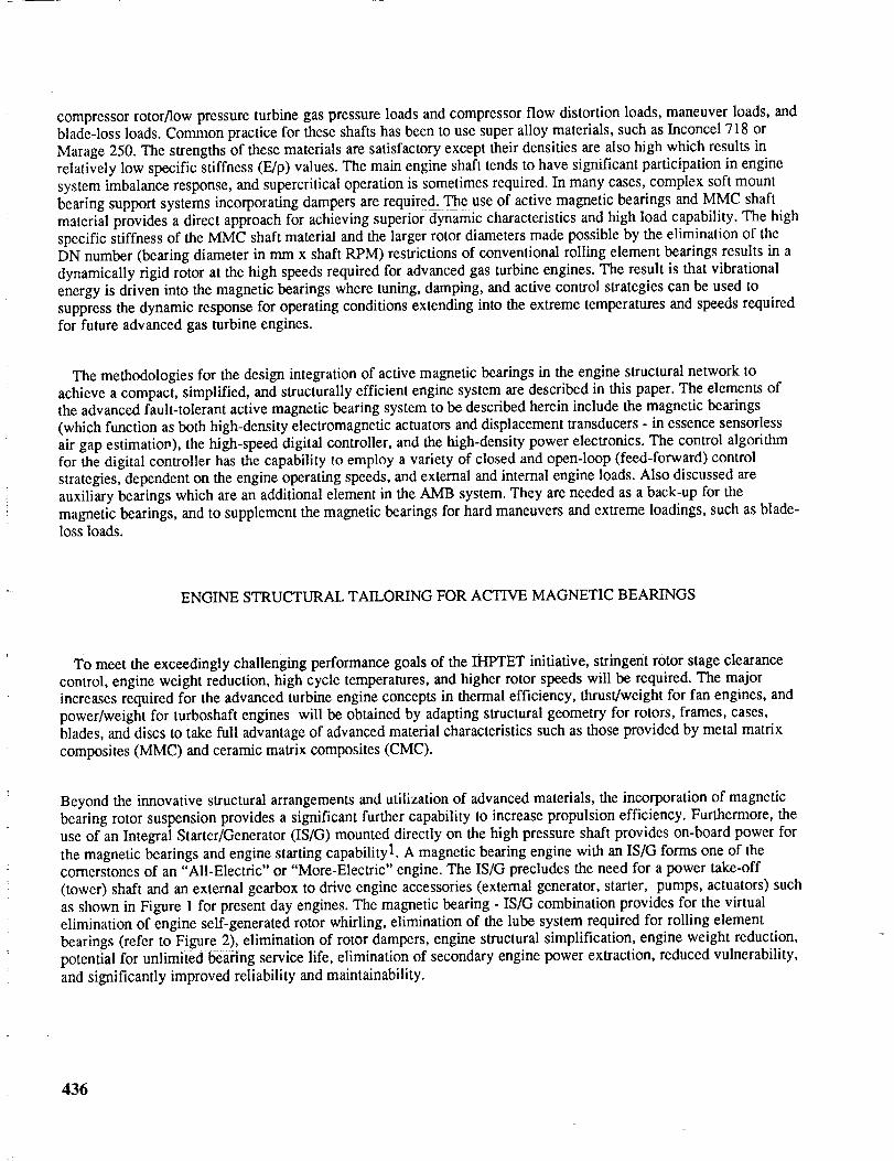
the magnetic bearings and engine starting capability 1. A magnetic bearing engine with an IS/G forms one of thecornerstones of an "All-Electric" or "More-Electric" engine. The IS/G precludes the need for a power take-off(tower) shaft and an external gearbox to drive engine accessories (external generator, starter, pumps, actuators) suchas shown in Figure 1 for present day engines. The magnetic bearing - IS/G combination provides for the virtualelimination of engine self-generated rotor whirling, elimination of the lube system required for rolling elementbearings (refer to Figure 2), elimination of rotor dampers, engine structural simplification, engine weight reduction,potential for unlimited bearing service life, elimination of secondary engine power extraction, reduced vulnerability,
and significantly improved reliability and maintainability.
436
_Z
I
z_
w_
wl--
)--
437

438

The synergism of magnetic bearings and improved component designs incorporating advanced materials permitsthe development of turbine engines with a fewer number of bearings while also achieving significant improvement inrotordynamics characteristics and greatly reduced sensitivity of rotor stage clearance closures due to maneuver loads.Consider the main engine or fan shaft. This shaft spans across the core engine and in conventional engines has a largelength-to-diameter ratio. In order to avoid critical speed problems and unacceptable maneuver load deflections at thefan and low pressure turbine for fan engines, redundant mounting is used. Figure 1 shows a large, present day fivebearing military engine which uses three rolling element bearings (Nos. 1, 2, and 5) to support the main shaft. Couplesupport across the No. 1 and No. 2 bearings reacts the large overturning moment generated by the fan during in-flight gyro maneuver conditions and provides the stiffness required to avoid fan nodding modes in the operatingspeed range. This couple support is needed to control fan tip deflection as very little moment carrying capability isprovided by the main shaft aft of the two forward bearings due to its low bending stiffness. This low bending stiffnessis caused by the relatively small outer diameter of the main shaft required to meet core rotor bearing DN number(approximately 1.5 million) and disk bore diameter limits. The bore diameters of the core rotor disks of present dayengines are minimized to maintain the stresses in the monolithic material disks within allowable limits at themaximum engine speeds. However, when magnetic bearings are used, DN numbers approaching or exceeding 3.5million (based on maintaining magnetic bearing rotor lamination stresses within allowable limits) are achievable. Inaddition, significantly increased allowable disk stress levels and the attendant larger disk bore diameters can beachieved through the use of circumferential fiber reinforced composite material, such as Titanium based MMC forthe compressor disks, and ceramic matrix composite for the turbine disk.
Throe Be_ag Support - S_r Two B_u'_n'l Sulq_ - SlilTAlloy MJdn Sb_ _ D;an_ MMC
M_n Sh_
Figure 3. Main Engine Gyroscopic Loading Deflections
The need for three bearing support of the main engine shaft to prevent unacceptable fan pitching under gyromaneuver and dynamic loads is eliminated through the use of magnetic bearings and a high stiffness main shaft.Fabricating the main shaft from Ti 6AL-2Sn-4Zr-2Mo matrix material reinforced with continuous ceramic (siliconcarbide) fibers allows the obtainment of high shaft stiffness. Note that the metal matrix composite (MMC) material isnot stiffer than super alloy materials presently used in turbine engine shafts. However, it has a lower density allowinglarger main shaft diameters to be used to obtain high stiffness without a weight penalty. The increase in high pressurerotor bore diameters required to obtain sufficient main shaft stiffness to permit two bearing support (at each end ofthe shaft with the two forward-couple bearings replaced by a single bearing) requires core rotor bearing DNnumbers in the range of 3.5 million - well within the capability of magnetic bearings. The equivalence between three
bearing support and an increased stiffness main shaft supported by two bearings is shown in Figure 3. In addition tocontrolling fan pitching due to gyro maneuVei; loads and avoiding fan nodding modes in the operating speed range,the high specific stiffness (E/e) MMC material reduces the participation of the main shaft mid-region in engine systemcriticals with the result that main shaft unbalanc_ response sensitivity is further decreased.
Running the reinforcing fibers parallel to the axis of the main shaft results in the greatest improvement of shaft
bending stiffness. However, in order to provide the required torsional strength, angle-ply fiber orientations are used.The MMC lamina are wrapped so that the fibers form a helix which advances along the shaft length. This scheme still
provides a significant payoff in increased absolute and specific stiffness in the axial direction. References2, 3 discussthe benefits in gas turbine engine structural efficiency and performance achievable through the use of metal matrixcomposites with continuous fiber reinforcement in component structures. Table 1 shows a stiffness comparison of Ti6-2-4-2/SIC angle-plied MMC material and selected super alloys at elevated temperature. Note the increased specificstiffness in the axial direction obtainable with angle-plied Ti 6-2-4-2/SIC MMC material.
439
TI 6-2-4-2/SICAnglePliedMMC
INCO718 RENE'95 MARAGE250
Density(lb/in3) 0.145 0.296 0.297 0.2891000°FModulus(MSI) 25 25 27 211000°FE/p(in) 172"10-6 84"10-6 91"10-6 73"10-6
Table1.Stiffness/WeightComparisonofTitanium-BasedMMCtoSelectedSuperalloys
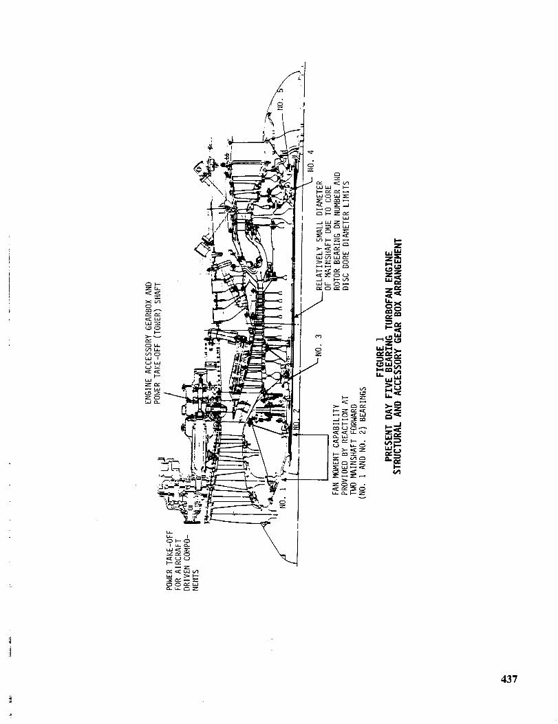
In additionto astiffmainshaft,thehigherDNnumbersmadepossiblebymagneticbearingsalsopermitastiffhighpressureorcorerotor.Thisresultsindynamicallyrigidrotorswiththeresultthatvibrationenergyisdrivenintothemagneticbearings.Thispermitsanumberof differentcontrolstrategiesto beeffectivelyusedto suppressrotorvibrationoverthecompleteoperatingspectrum.Thesecontrolstrategieswill bediscussedlaterin thispaper.
It shouldbenotedthatauxiliaryorback-upbearingsareanintegralpartof themagneticbearingdesign.Thesebearingsaredesignedto operateatapproximatelyhalftheclearanceof themagneticbearingsandthuspreventdamagetothemagneticbearingsattouchdown.In additiontoprovidingsupportduringshipment,storage,andfor allothernon-operationaltime,theauxiliarybearingssharemomentaryoverloadsdueto shockandblade-loss,andprovidesupportfollowingmagneticbearingfailure.Therearetwolikelycandidatesfor theauxiliarybearings.Thefirstauxiliarybearingcandidateisahydrostaticgasbearingintegratedwiththemagneticbearingstructureandconfiguredtoactinparallelcontinuouslyorbeactivatedondemand.Thisgasbearingwouldbesupplementedbyaselflubricatedsleevebearingforshock-andextreme-loadconditionsaswellasatlowenginespeeds(belowidle).Thesecondauxiliarybearingcandidateisadry-lubricated,high-temperature,rolling-elementbearingdesignedtooperatefor shortperiodsatabove3.0millionDNattemperaturesabove800° F. Todissipatetheheatgeneratedbythedry-lubricatedbearing,coolingairwill besuppliedbyenginebleed.Lubricationcanbeprovidedbyadrypowderdeliveredto thebearingfromanemergencycanisteractivatedwhenalossof rotorcontrolis sensedbythemagneticbearingcontroller.Thefollowingdrybearingconfigurationsarecandidatesfor auxiliarybearings:ahybridwithroilingelementsandtungstenalloyraces,ahybridwithrollingelementsandintermetallicraces,andanall fiber-reinforced-ceramicbearing.
_tarter QenaratorRadial Beadng
Thrust Axial Thrust Axial
Bearing Beating Radial Beating
Figure 4. Advanced Four Bearing Turbofan Engine withMagnetic Bearings and Integral Starter/Generator
440

Figure4 showsasimplifiedenginestructuralnetworkmadepossiblebyfull magneticbearingintegrationandincorporationof anintegralstarter/generatoronthehighpressurespool.Thesetechnologiespermita fourbearingconfiguration,andtheeliminationof thelubesystem,powertake-offshaft,andtheexternalgearbox.In additiontosignificantlyimprovedreliabilityandmaintainability,theweightsavingsaresubstantial,amountingtomorethan200lbsfor a largemilitaryengine.
CONTROLALGORITHMS
A digitalcontrollerwill beusedto implementcontrolalgorithmsforrotorstabilizationandvibrationreduction.Itwill benotedthatadigitalcontrollerpermitstheeasychangeof controlalgorithms.Hence,awiderangeof controloptionsareeasytoimplementfor themagneticbearingsuspensioncontrolsystem.Thecontrolstrategiesfall intotwocategories:ClosedandOpenLoopControl.Theformeris incorporatedintothefeedbackloopandcanimpactstabilityof theactivemagneticbearingsystem.Thelatterisafeed-forwardmethodwherebyexternalcontrolforcesaresuperimposedonthefeedbackcontrolforcestoreducevibration.Thismethodseparatestherotorsuspensionandvibrationcontrolproblems,andthuspermitsthefeedbackcontroltobedesignedsolelytoprovidemaximumstability.
Twoapproachesthatcanbeusedtoimplementclosedloopcontrolareadaptivestiffness/dampingcontrol,andthetrackingnotchfiltermethod.Theformermethodreducesvibrationbycriticalspeedtuningandvibrationenergydissipation.Thisis accomplishedbyvaryingbearingstiffnessanddampingtoeliminateresonancesor toheavilysuppressresponseatrotorcriticalspeeds.Thismethodcanproviderobustperformancewhentheshaft/bearingsystemis subjectedtoexternaldisturbances.Forthelatterclosedloopmethod,atrackingnotchfilter isplacedin thefeedbacklooptopermitaccommodationofsynchronousdisturbances.Thiscausesthemagneticbearingtohavegreatlyreducedstiffnessanddampingattherunningspeed,thusdesensitizingtherotorto imbalancebecauseit tendstospinaboutits inertialaxis.
Theopen-loopcontrolcanbeimplementedaseitheranactivevibrationcontrolscheme,orasabearingsynchronousforcecancellationschemeforselectedfrequencies.Typically,fortheformerapproach,vibrationdisplacementsarecanceledatthemagneticbearingplaneoratsomeotherlocation,suchasontheenginecasing.Thisisadisturbancerejectionmethodandisaccomplishedbytheinjectionofopen-loopforceswhichcanbecalculatedusinginfluencecoefficients.In thelatteropen-loopapproach,theforceactuatorcommandscanbeadjustedsoastoeliminatethesynchronouscomponentof theseforces.Thisdisturbanceaccommodationapproachcanbecharacterizedasanopen-loopnotchfilterasthebeatingsexertnoactivesynchronousforces,whichresultsinisolationof therotorattherunningfrequency.
Effectivecontrolof themagneticbearing/rotorsystemwill requiretheimplementationof acombinationof thecontrolelementsdiscussedabove,Forexample,activevibrationcontrolaccomplishedthroughtheinjectionof open-loopforcescanbeusedfor low speedoperation(rotorstart-upto idlespeed)tocancelrotorsynchronousvibrationdisplacementsatthemagneticbearingplanes.In thisscheme,theengineismodeledon line through the generation ofdynamic influence coefficients which are used to construct reduced dynamic stiffness matrices used in the calculationof vibration canceling forces. One method to obtain the influence coefficients involves processing trial force signalsinjected at the magnetic bearings and the resulting response signals at discrete rotor speed points during exploratoryaccels/decel-s. This method isadaptive in that the amplitudes and phases of the corrective forces are dependent on theengine speed, vibratory characteristics, and imbalance levels, and the influence coefficients are updated to reflectchanges in the engine system frequency response characteristics. The influence coefficients and measured responseare then used to calculate corrective forces which are used in an open loop mode to cancel the synchronous responsedue to rotor imbalance. Since the synchronous response is highly correlated, it may be altered without feedback.
Thus, the system stability is not affected by the open loop control. This active vibration control method would not beused for high speed operation because the injected forces needed to reduce displacement levels at the magnetic bearingsensors can actually increase the transmittal forces at the magnetic bearings in this speed regime.
441

For operation above idle speed, the closed or open-loop notch filter method can be used to suppress synchronousvibration. This method is not suitable for low speed operation in the vicinity of the rigid body criticals (resultingfrom bearing stiffness suppression) because the synchronous imbalance response is basically uncontrolled in this speedregime.
ELECTROMAGNETIC ACTUATORS
Figure 5 shows a fault-tolerant radial magnetic bearing. The bearing uses 3 radial control axes which are made upof 12 electromagnetic stator poles organized into 6 force-producing pole-pairs with 60 ° radial spacing. Two pole-pairsat 180 ° radial separation combine to create a single control axis.
Non-Magnetic Flux Barriers
6rail Hiperco 50 Laminations Welded to laminations
1.0
0.8
8
0.4
10.2
0.0200 400 600 800
Tempecature ('C)
i
1000
Figure 5 - Fault-Tolerant Radial Magnetic Bearing Figure 6 - Effect of Temperature onCobalt-Iron Force-Production Capability
The stator core is segmented with non-magnetic sections in order to minimize the magnetic coupling betweenadjacent pole-pairs. The magnetic isolation provided by the stator segmentation will allow non-faulted force-actuationpole-pairs to continue functioning in the proximity of faulted magnetic poles. Since any 2 of the 3 (or more) controlaxes are sufficient to maintain rotor suspension, the third control axis in this magnetic structure provides inherentredundancy and given appropriate control measures, continued bearing operation in the presence of a variety of fauIts(e.g. faulted magnetic poles, power electronic shorts, phase power loss, etc.) is possible. Greater inherentredundancy/fault tolerance can be readily achieved by adding more than 3 axes of control.
This magnetic structure for the stator can be constructed using a stack of composite laminations as has been done forelectric machine rotors4, 5 or by bonding solid non-magnetic segments to a stack of laminations as has also been done
for electric machine rotors4, 5. The bearing laminations are made from a Cobalt-Iron alloy which has superiormagnetic, thermal degradation and mechanical properties, but is slightly more lossy than alternative materials. Amaximum operating temperature is chosen as a compromise between bearing size and cooling requirements. Bleed airwould be used to limit the temperatures. Figure 6 shows the effect of temperature on per unit force productioncapability of Cobalt-Iron laminations.
442
The magnetic material used for rotors has to withstand the centrifugal force induced stresses at maximum rotor
speed and maximum temperature. Cobalt-Iron in its normal anneal at 1550°F (840°C) has a 0.2% yield of 44 ksi up to300°F (150°C). At temperatures of 500°F (260°C) this reduces to less than 40 ksi. A second material option is the1350°F (740°C) anneal version of the same Cobalt-Iron. This material has a 0.2% yield of better than 80 ksi at 140°C
and remains much stronger at higher temperatures (75 ksi at 500°F). The price paid for the higher strength is 5 to
10% reduction in maximum force production capability and higher rotor eddy current losses.
The stator windings must withstand temperatures significantly higher than the magnetic material since heat transferfrom the windings to the stator is generally poor. A silicon-mica based insulation system, Thermidur, as demonstratedby Siemens, Germany, for 10,000 hrs life at 752°F with occasional excursions to 932°F is preferred.
ELECTRONIC (SENSORLESS) POSITION ESTIMATION
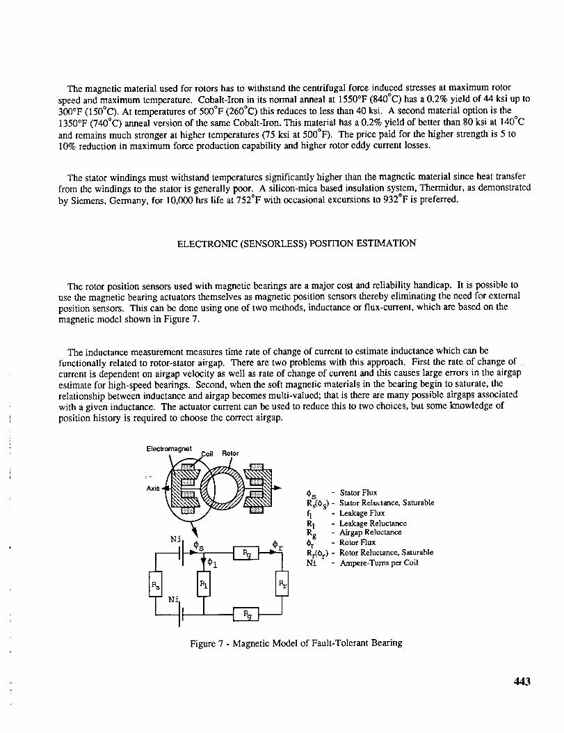
The rotor position sensors used with magnetic bearings are a major cost and reliability handicap. It is possible touse the magnetic bearing actuators themselves as magnetic position sensors thereby eliminating the need for externalposition sensors. This can be done using one of two methods, inductance or flux-current, which are based on themagnetic model shown in Figure 7.
The inductance measurement measures time rate of change of current to estimate inductance which can be
functionally related to rotor-stator airgap. There are two problems with this approach. First the rate of change ofcurrent is dependent on airgap velocity as well as rate of change of current and this causes large errors in the airgapestimate for high-speed bearings. Second, when the soft magnetic materials in the bearing begin to saturate, therelationship between inductance and airgap becomes multi-valued; that is there are many possible airgaps associatedwith a given inductance. The actuator current can be used to reduce this to two choices, but some knowledge of
position history is required to choose the correct airgap.
Electromagnet " Rotor
AxisOs - Stator Flux
Rs(0s ) - Stator Reluctance, Saturable
fl - Leakage FluxR! - Leakage ReluctanceRg - Airgap ReluctanceOr - RotorFluxRr(0r) - Rotor Reluctance, SaturableN:L - Ampere-Turns per Coil
Figure 7 - Magnetic Model of Fault-Tolerant Bearing
443

= fv- irThe flux-current method uses the relationship Cs j_-dt to determine the flux in an excited winding. Then,
given the actuator current and a suitable magnetic model of the actuator, a unique rotor-stator airgap can bedetermined. This method works regardless of airgap velocity or magnetic saturation. The primary difficulty here isin maintaining an accurate flux estimate where the excitation waveform is not cyclic and the required integratorcannot be reset periodically. This method has been used successfully with switched reluctance motors6,7.
FAULT-TOLERANT ENGINE ELECTRICAL SYSTEM
Figure 8 illustrates a conceptual electric system for an advanced aircraft engine. This is a fault-tolerant systemrelying on 3 independent 270 vdc buses for distribution amongst a variety of loads, including active magnetic bearing
(AMB) controls and power electronics.
Redundant I FADECEAN Power & Engine Control System
Communications
270 VDC
(A)
270 VDC(B)
270 VDC
(c)
BSC: Bearing System ControllerAXC: Axis Controllers
EAN: Engine Area Network
BSC
1!
!
i i
BSC
Radial Radial Axial Radial Radial Axial
Bearing Bearing Bearing Beating Bearing BearingAI A2 AI B1 B2 BI
Compressor Spool
Magnetic Bearings
Fan/Power Spool
Magnetic Bearings
Figure 8. More Electric Engine Electrical System
The 3 distribution buses would appear to represent a conventional triple modular redundancy with 200%overcapacity, but this is not the case. The electric distribution system would be designed for 50% over-capacity, i.e.,each bus designed for 50% of the needed system capacity, thereby requiring 2 of the 3 buses at any time in order to
avoid system failure.
The radial active magnetic bearings are configured with 3 magnetically independent control axes per bearing
placed at 60 degrees radial separation. These 3 control axes cooperate to control the radial rotor position such that
444

controlcanbemaintainedwithonly2 of thecontrolaxesfunctioning.Eachof the3bearingcontrolaxesarepoweredfromadifferentdcbus;thereforetheradialbearingsrequire2 activedcdistributionbusesin orderto maintainrotorpositioncontrol.Thetotalavailableforcevectoris angledependent,butis aminimumof 0.866timestheforcecapacityof asinglecontrolaxis.
Theaxialactivemagneticbearingsareconfiguredinasimilarfashionwith3magneticallyindependentcontrolaxes,eachcontrolaxiswith50%forcecapability- thus2of the3 availablecontrolaxesarerequiredfor ratedthrustloading.Eachof theaxialcontrolaxesarealsofedfromdifferentdcelectricaldistributionbuses.
MAGNETICBEARINGCONTROLS
Themagneticbearingcontrolsconsistof 2hierarchicallevels:asupervisorylevel- BearingSystemController(BSC),andanactuationlevel- AxisController(AXC).Thesupervisorcontrollersareconfiguredin aduplexfaulttolerantconfiguration,withonesupervisorin activecontrolandthesecondinanactivestandbymode.EachBearingSystemControllerisconfiguredtocontroloneenginespool(8controlaxes).
Theactuationcontrollersareessentiallysmart,self-protecting,poweramplifierscapableof excitingasingleindependentAMBaxis(2electromagneticwindings,+ and-). A radialbearingwill thusrequire3AXC's.Eachactuationcontrolleriscapableof acceptingcommandsfromanddeliveringfeedbackinformationtomultiplesupervisors,therebyenablingredundancyatthesupervisorlevel. =
_mmunle_11ons Commun;ealiDns Communications Comrrmnioi6ons
& Power LinklA & PowerLink 1B & PowIUnk2A & F_erLink2B
Commun_r_l_ns Communications Cc_lmurlk;allon$ CommunIcallons
&PowlwLinklA &PowefLinklB &P_vell.laklA &PowecUnk2B
I I tae_ai'ing SY s lem !°ntr °li _ ]
_sA _sE ksC
Figure 9. Twin Spool Active Magnetic Bearing Control System with Duplex Supervisor
The duplex supervisory controllers are essentially an extension of the dual-redundant engine controller (FADEC)acting as intelligent hlgh-bandwidth actuators, The supervisor controllers are powered from the FADEC controlpower and communicate with the FADEC via a multi-drop Engine Area Network (EAN). Two redundant EANcommunication/control power channels are provided. An actuation controller is powered, along with the powerelectronic switches it controls, directly from an individual dc electrical distribution bus. Communication between thesupervisory and actuation levels is accomplished in a manner to maintain electrical isolation e.g. fiberopticcommunication links.
Figure 9 illustrates the active magnetic bearing controller architecture for a twin spool engine. Each spool has aduplex supervisory Bearing System Controller which is responsible for coordinated control of the rotor position,vibration, and imbalance - this coupled control will execute at a 6.7 kHz task execution rate and transmit new forcecommands to the axis controllers. The Axis Controllers are responsible for force control & linearization, gap
445

position & velocity inference, fault detection & isolation - the axis controller will execute at a 20 kHz task executionrate which results in power electronic switching at an equivalent frequency.
Each axis controller is capable of accepting 2 command streams from each of the duplex Bearing SystemControllers via high-bandwidth half-duplex serial communication channels. The controlling supervisor will transmit acurrent state information packet, once per control iteration, to the active standby BSC both as a heartbeat indicatorand to enable a smooth transition to the backup supervisor if required. The supervisory controllers for each enginespool are capable of communicating once per control iteration with each other to transmit required dynamiccoupling information. The BSC peer-peer communications are high-bandwidth full duplex serial communicationslinks. The BSC's are also required to communicate with the FADEC over slower half-duplex communication links.
AMB SYSTEM MODELING AND SIMULATION
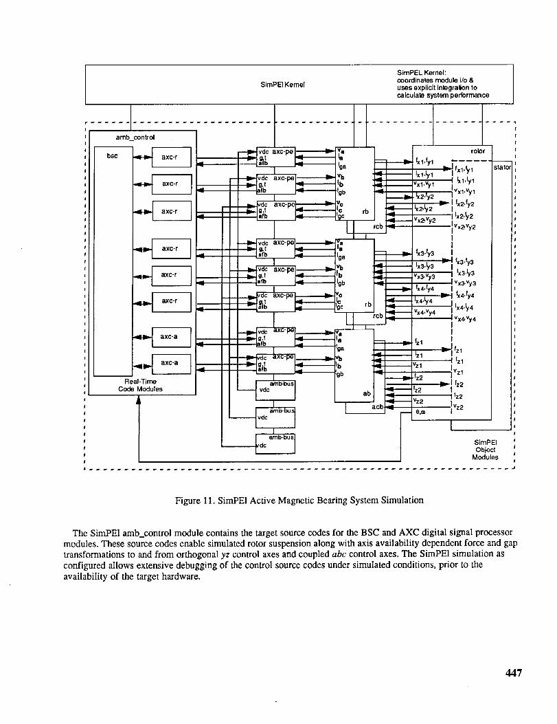
Figure 11 illustrates a SimPEI simulation of the AMB control system. SimPEI (Simulator for Power Electronics) isan object-oriented dynamic simulator developed by GE CR&D. SimPEI uses explicit numerical integrationprocedures to predict the responses of dynamic systems. Each of the physical elements of an active magnetic bearingsystem have been included, including the three 270 vdc buses (amb-bus in Fig. 11), axis controller power electronicconverters (axc-pe), radial & axial bearing magnetic actuators (rb and ab), rotor dynamics (rotor), axial & radialcatcher bearings (rcb and acb), bearing mechanical support structures (stator), and the AMB control system itself(amb_control). The rotor model includes rigid body rotor dynamics which are currently being extended to includeflexible-rotor modeling. The magnetic bearings are modeled using the model shown in Figure 7. Figure 10 illustratessimulated radial bearing force waveforms produced by SimPEI.
ID
od
500.0
300.0
100.0
-100.0
-300.0
-500-00.002
AMB Controller Force
10 gin-in Rot.or Imbalance @ 12,500 rom' I ' I '
, I , I0.004 0.006
"nine(s)
).008
Figure 10. Force Waveforms with 20 kHz Ripple
446
SimPEL Kernel:coordinates module i/o &
SimPEI Kernel uses explicit integration to
calculate system performance
bsc ,IH_ axc-r .- _axc-pe,_ _Pia _:_ fx1,fyl =.,j_ _ ....
'_I axc-r I I-I _ "_d_ Lxc-pe._ _ i_ _ i:::'v_: 1 _ If_11,1_1 saor
/ I _ I _ I _'b _ gb ._1 I Ix2f 2 IlVxl'Vyl
,,_ axc-r I _ r- i L_!agi_ I _ l_Cl I rb !,.._._:2_v_ 2 lllx2,ty 2 ,
-- , _ I -!.il, _ io,, , , _ ,_,,3.f,_d f f
axc-r _1_ b _ -x_,-y;J I ,ly"_ I _ , _-"-"_'_----"_ g ,_1 - It. 4r 4 ; 'Y! _ lafb I b _ . . Vx3V 3 ,
, , __ ,..:o I ,t-_!,_: _ _,.,,,axc-r -- I _Ig_ t _ g_c rb _ 'x4,'y4. i ix4,1y4 I
I _ I I rcb _ x4 y4 'w_v--
• I _ ..:.4--1 - j_ I i "'_" ' '
C I_
I
Modules
Figure l 1. SimPEI Active Magnetic Bearing System Simulation
The SimPEI amb_control module contains the target source codes for the BSC and AXC digital signal processormodules. These source codes enable simulated rotor suspension along with axis availability dependent force and gaptransformations to and from orthogonal yz control axes and coupled abc control axes. The SimPEl simulation asconfigured allows extensive debugging of the control source codes under simulated conditions, prior to theavailability of the target hardware.
447

GE MAGNETIC BEARING TEST RIG
The test rig shown in Figure 12 has been developed by General Electric for validation testing of advanced magneticbearings and digital controls/power electronics systems. This effort will encompass programs for the use of magneticbearings for marine and aeroengine main shaft support and applications for stationary power plant turbomachinery andgenerator rotor support. The conventional proximity sensors depicted in Figure 12 will be used initially for rotordisplacement calibration measurements. Later, the sensorless air gap estimation technique based on utilizing themagnetic bearings as both force actuators and displacement transducers will be used.
Figure 12. GE Single Spool Magnetic Bearing Test Rig
The test rig utilizes two radial magnetic bearings located fore and aft, an excitation radial magnetic bearing locatedat approximately mid-span, a thrust magnetic beating, and a thrust excitation magnetic bearing. The forward directionis to the left. Radial auxiliary bearings are mounted out-board of the radial magnetic bearings. The radial auxiliarybearings are turbine engine class bearings, and the radial clearance between the shaft OD and the bearing inner ring IDis equal to 10 mils. This precludes the possibility of damage to the radial magnetic bearings for overloads or rotordrop as the radial clearance of the magnetic bearings is equal to 20 mils. An axial auxiliary or bumper bearing isutilized to prevent damage to the thrust magnetic bearing.
Overhung disks located fore and aft simulate a fan and turbine and provide balance planes for mechanical balancing.An additional balance plane is available at the disk of the thrust excitation magnetic bearing. The rig is driven by a 20HP electric motor through a quill drive shaft located at the aft end of the rotor.
General Electric will be developing a generic two shaft magnetic bearing test rig for use in dual rotor magneticbearing engine studies. This will be accomplished by developing a shaft/case module and coupling case to permitexpansion of the single shaft rig shown in Figure 12 into a two-shaft magnetic bearing test rig. The two shaft rig willprovide experience and proven methodologies for use in the design of future twin spool magnetic bearing engines.
Figure 13 shows initial layouts for the two shaft magnetic bearing test rig. The lower configuration has a tuningspring (shown as an outer case over the right shaft/case module) which may be necessary to achieve dynamic couplingbetween the two shafts representative of two spool engine dynamics.
448

IJJ d ,
D_IVE SltAFT SFOOL 2 VO[XILE SPOOL ! VODULE OR]VE S.I_FT
FOR SPOOL Z FOR SPOOL 1
Figure 13. GE Twin Spool Magnetic Bearing Test Rig Configurations
ACKNOWLEDGMENT
The work reported herein dealing with controls, control algorithms, fault tolerance, and AMB system modeling
and simulation was carried out using internal GE funding. This technology is being further enhanced under the
auspices of an Army program awarded to GE Aircraft Engines by the Aviation Applied Technology Directorate
(AATD), U.S. Army Aviation and Troop Command, Fort Eustis, Virginia 23604-5577, under contract DAAJ02-92-
C-0055. The contributions, suggestions, and encouragement of Bert Smith, the Army Program Manager for Magnetic
Bearings, are greatly appreciated.
REFERENCES
.
2.
3.
4.
5.
6.
.
Richter E., Anderson R. E., Severt C., The Integral Starter�Generator Development Progress, SAE Paper
920967, April 1992.
Storace, A. Turbine Engine Structural Efficiency Determination, AIAA 89-2571, July 1989.
Signorelli, R.A., Metal Matrix Composites for Aircraft Engines, NASA Technical Memorandum 83379, April1983.
Composite Rotor Lamination for Use In Reluctance, Homopolar and Permanent Magnet Machines, U.S. PatentNo. 4,916,346, Inventor: G.B. Kliman, assigned to GE, Dec. 28, 1987.
Method of Fabricating Composite Rotor Laminations for Use In Reluctance, Homopolar and Permanent Magnet
Machines, U.S. Patent No. 4,918,831, Inventor: G.B. Kiiman, assigned to GE, Oct. 20, 1989.
Lyons, J.P., MacMinn, S.R., and Preston, M.A., Flux�Current Methods For SRM Rotor Position Estimation,
Proceedings of the 1991 IEEE Industry Applications Society Annual Meeting, Sept. 28-Oct. 4, 1991, Dearborn,
MI, pp. 482-487.
Preston, M.A. and Lyons, J.P., A Switched Reluctance Motor Model with Mutual Coupling and Multi-Phase
Excitation, IEEE Transactions on Magnetics, Vol. 27 No. 6, Nov. 1991, pp. 5423-5425.
!
t449


![untitled [] · Web viewFormat di PDP a cura di Annapaola Capuano, Franca Storace, Luciana Ventriglia8A. Capuano, F. Storace, L. Ventriglia, BES e DSA. La scuola di qualità per tutti,](https://img.dokumen.tips/doc/110x75/61143241230fef1a8b7db436/untitled-web-view-format-di-pdp-a-cura-di-annapaola-capuano-franca-storace.jpg)