Embed Size (px)
Citation preview
THE CITY OF GALVESTON STRUCTURAL FIELD WELDING
16448-1
SECTION 16448
STRUCTURAL FIELD WELDING
PART 1 DESCRIPTION
A. Field-weld metal members using the shielded metal arc and flux-cored arc welding
processes.
PART 2 MATERIALS
A. Provide electrodes for shielded metal arc welding (SMAW) conforming to the
requirements of the latest edition of ANSI/AWS A5.1, “Specifications for Mild Steel
Covered Arc Welding Electrodes,” or ANSI/AWS A5.5, “Specifications for Low-
Alloy Steel Covered Arc Welding Electrodes.”
B. Provide electrodes for flux-cored arc welding (FCAW) conforming to the
requirements of the latest edition of ANSI/AWS A5.20, “Specification for Carbon
Steel Electrodes for Flux Cored Arc Welding,” or ANSI/AWS A5.29, “Specification
for Low-Alloy Steel Electrodes for Flux Cored Arc Welding.”
C. Provide electrodes and flux-electrode combinations named on the approved list as
discussed in Section 16000. To request that a product be added to this list or to renew
an expired approval, the Contractor or the consumable manufacturer must submit
certified reports of all tests required by the applicable AWS A5 specification
according to the applicable welding code. For most structural steel construction, the
applicable welding code is AASHTO/AWS D1.5, Bridge Welding Code, or
ANSI/AWS D1.1, Structural Welding Code—Steel. For reinforcing steel, the
applicable code is ANSI/AWS D1.4, Structural Welding Code—Reinforcing Steel.
Tests must be conducted on electrodes of the same class, size, and brand and
manufactured by the same process and with the same materials as the electrodes to be
furnished. Resubmit electrodes or flux-electrode combinations every 12 months for
renewal.
D. Table 1 shows the classes of electrodes required. Use electrodes with the type of
current, with the polarity, and in the positions permitted by AWS A5.1 and A5.5 for
SMAW. AWS A5.20 and A5.29 specifications govern for FCAW. Obtain approval
for electrode use on steel not listed in Table 1.
THE CITY OF GALVESTON STRUCTURAL FIELD WELDING
16448-2
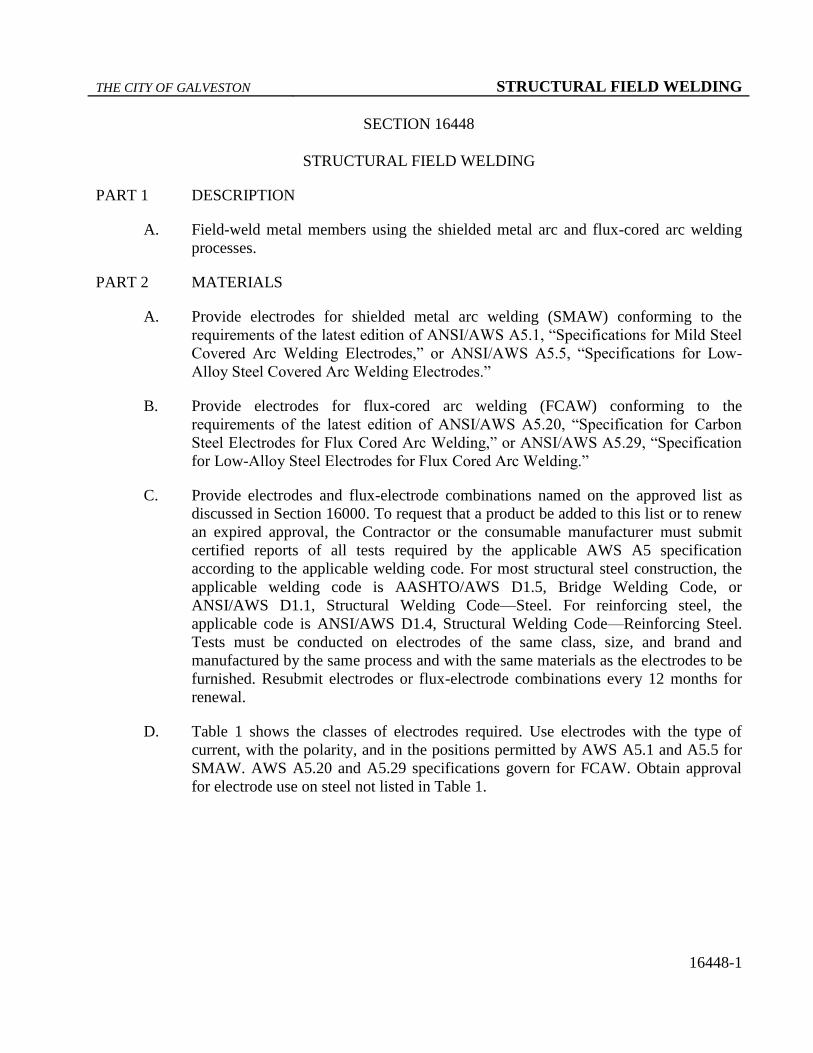
Table 1
Classification of Electrodes Permitted
Type of Steel
(ASTM
Standards)
Electrode
Specification
Process Filler Metal
Requirements
Steel piling
Armor joints
A 500
A 501
AWS A5.1 or
A5.5
SMAW E60XX
E70XX or
E70XX-X
AWS A5.20 or
A5.29
FCAW E6XTX-X
E7XTX-X
(except -2, -3,
-10, -GS)
A 36
A 572 Gr. 50
A 588
A 242
A 709 Gr. 36. 50,
or 50S
AWS A5.1 or
A5.5
SMAW E7016
E7018
E7028
AWS A5.20 or
A5.29
FCAW E7XT-1
E7XT-5
E7XT-6
E7XT-8
Weathering steel
A 588
A 242
A 709 Gr. 50W
AWS A5.5 SMAW E8018-W
E8016-C3
E8018-C3
E8016-C1
E8018-C1
E8016-C2
E8018-C2
AWS 5.29 FCAW E8XT1-W
E8XTX-Ni1
E8XTX-Ni2
E8XTX-Ni3
A 709
Gr. HPS 70W
AWS A5.5 SMAW E9018-M-H8R
Reinforcing steel
Grade 40
AWS A5.1 or
A5.5
SMAW E70XX
Reinforcing steel
Grade 60
AWS A5.5 SMAW E90XX
Permanent metal
deck forms
AWS A5.1 or
A5.5
SMAW E6010
E6011
E6013
E7018 Note: Low-hydrogen electrodes applicable to the lower strength base metal may be used in
joints involving base metals of different yield points or strengths.
E. E7010 and E8010 electrodes may be used when welding the root passes of beam and
girder splices if the requirements of Section 16448, Part 4, 4.03, E, 4, a, “High-
Cellulose Electrodes for Root Passes,” are met.
F. When welding fracture-critical applications, use electrodes meeting the diffusible
hydrogen requirements for fracture-critical welding in AASHTO/AWS D1.5.
G. For FCAW, use gas or gas mixtures that are welding grade and have a dew point of
−40ºF or lower. Furnish certification to the Owner’s Representative that the gas or
THE CITY OF GALVESTON STRUCTURAL FIELD WELDING
16448-3
gas mixture is suitable for the intended application and will meet the dew point
requirements.
PART 3 EQUIPMENT
A. Provide electrode drying and storing ovens that can maintain the required
temperatures specified in Section 16448, Part 4, 4.03, A, “Electrode Condition,”
along with thermometers for checking and controlling the oven temperatures. Provide
preheating equipment that can maintain the entire joint at or above the specified
temperature. Provide approved equipment for checking preheat and interpass
temperatures at all times while welding is in progress. Provide welding equipment
meeting the requirements of the approved welding procedure specification (WPS), if
required, and capable of making consistent high-quality welds.
PART 4 CONSTRUCTION
4.01 PROCEDURE QUALIFICATION
A. Use the proper classification and size of electrode, arc length, voltage, and amperage
for the thickness of the material, type of groove, welding positions, and other
circumstances of the work.
B. Submit WPS’s for FCAW, qualified in accordance with AASHTO/AWS D1.5, for
approval before any field welding on a project.
4.02 WELDER QUALIFICATION
A. Provide to the Owner’s Representative certification papers for each welder for each
welding process to be used before welding, except for miscellaneous welds described
in Section 16448, Part 4, 4.02, A, 1, a, (1), “Miscellaneous Welding Applications.”
Certification is issued by the Owner’s Representative as described in Section 16448,
Part 4, 4.02, A, 2, “Certified Steel Structures Welder.”
1. Miscellaneous Welding
a. A qualified welder is an experienced welder who is capable of making
welds of sound quality but does not have Owner’s Representative
certification papers. Before welding begins, the Owner’s
Representative will check the welder’s ability by conducting a job-site
test in accordance with Section 16448, Part 4, 4.02, A, 1, a, (2),
“Miscellaneous Weld Qualification Test.” Furnish all materials and
equipment necessary for this test.
(1). Miscellaneous Welding Applications

THE CITY OF GALVESTON STRUCTURAL FIELD WELDING
16448-4
(a). A welder certified for structural or reinforcing steel or a
qualified welder may make miscellaneous welds of the
following types:
1) splicing reinforcing steel to extend bars in the
bottom of a drilled shaft;
2) attaching chairs to the reinforcing steel cage of a
drilled shaft;
3) armor joints and their supports;
4) screed rail and form hanger supports where
permitted on steel units;
5) reinforcing steel to R bars for lateral stability
between prestressed beams, spirals, or bands to
reinforcing bars in drilled shaft cages;
6) permanent metal deck forms;
7) additional steel added in railing when slip-form
construction is used; and
8) other similar miscellaneous members that have
no load-carrying capacity in the completed
structure.
(2). Miscellaneous Weld Qualification Test
(a). A qualified welder must pass a job-site Miscellaneous
Weld Qualification Test before welding:
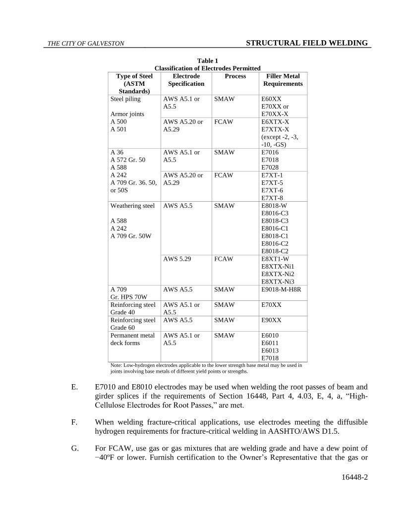
1) Make a single-pass fillet weld of 1/4 in.
maximum size in the vertical position
approximately 2 in. long on 1/2 in. plate in the
location shown in Figure 1. Use the same
electrode proposed for the work.
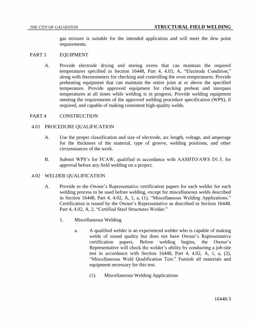
2) The Owner’s Representative will visually
inspect the fillet weld for a reasonably uniform
appearance and then rupture the weld as shown
in Figure 2 with a force or by striking it with a
hammer.
3) The fractured surface of the weld will be
inspected to ensure complete penetration into
the root of the joint, complete fusion to the base
metal, and no inclusion or porosity larger than
3/32 in. in its greatest dimension.
THE CITY OF GALVESTON STRUCTURAL FIELD WELDING
16448-5
Figure 1
Miscellaneous qualification—fillet weld break specimen.
Figure 2
Miscellaneous qualification—method of rupturing specimen.
(b). A welder who fails the Miscellaneous Weld
Qualification Test may take a retest under the following
conditions:
1) The retest occurs immediately and consists of 2
test welds as described above with both test
specimens meeting all of the requirements.
2) The retest occurs after 30 days if the welder
provides evidence of further training or practice.
In this case the test consists of a single test
weld.
THE CITY OF GALVESTON STRUCTURAL FIELD WELDING
16448-6
(c). Qualification by the Miscellaneous Weld Qualification
Test is effective immediately upon satisfactory
completion of the test and remains in effect for the
duration of a project.
2. Certified Steel Structures Welder
a. Before making non-miscellaneous welds on structural steel, a welder
must pass the AASHTO/AWS D1.5 qualification test for groove welds
for plates of unlimited thickness in the vertical (3G) and overhead
(4G) positions with the following additional requirements:
(1). Use metal for test plates that meets Section 16442, “Metal for
Structures,” with a minimum yield point of 50 ksi.
(2). Use approved electrodes meeting the required class in
accordance with Table 1 and, in the case of FCAW, in
accordance with the approved WPS.
(3). Have a radiographic inspection performed on the weld on each
test plate. Any porosity or fusion-type discontinuity with
greatest dimension larger than 1/16 in. found in the weld will
result in failure of the test. Discontinuities with greatest
dimension less than 1/16 in. are acceptable provided the sum of
their greatest dimensions does not exceed 3/8 in. in any inch of
weld.
(4). Have two side-bend specimens prepared, tested, and inspected
for each test plate.
b. The test must be administered by an approved laboratory. Submit 2
copies of the certification issued by the laboratory, all accompanying
test papers, and the radiographic films to the Owner’s Representative
for review. The Owner’s Representative issues certification papers if
the laboratory’s certification is approved. A welder must also
demonstrate to the Owner’s Representative a thorough knowledge of
the required welding procedures together with the ability and desire to
follow them and make welds of sound quality and good appearance.
The certification issued by an approved laboratory is accepted for 1
month from the time of certification, during which time the welder
may work on City projects if the work is satisfactory. Certification
papers issued by the Owner’s Representative remain in effect as long
as the welder performs acceptable work as determined by the Owner’s
Representative. The certification may be cancelled at any time if the
welder’s work is not acceptable.
c. For SMAW, a welder certified using EXX18 electrodes is qualified to
weld with all approved SMAW electrodes up to E90XX to join metals
with a maximum specified yield strength of 65 ksi.
THE CITY OF GALVESTON STRUCTURAL FIELD WELDING
16448-7
4.03 WELDING STEEL STRUCTURES
A. Electrode Condition
1. SMAW
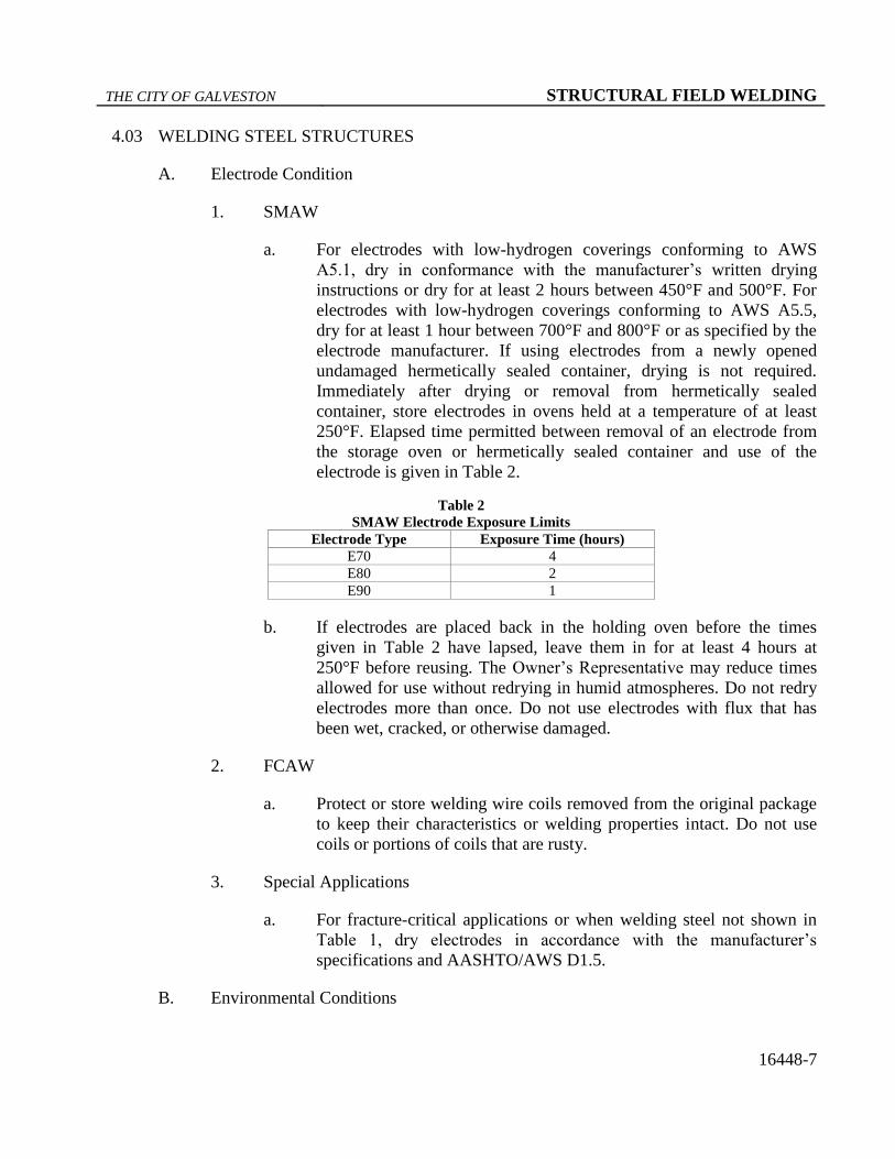
a. For electrodes with low-hydrogen coverings conforming to AWS
A5.1, dry in conformance with the manufacturer’s written drying
instructions or dry for at least 2 hours between 450°F and 500°F. For
electrodes with low-hydrogen coverings conforming to AWS A5.5,
dry for at least 1 hour between 700°F and 800°F or as specified by the
electrode manufacturer. If using electrodes from a newly opened
undamaged hermetically sealed container, drying is not required.
Immediately after drying or removal from hermetically sealed
container, store electrodes in ovens held at a temperature of at least
250°F. Elapsed time permitted between removal of an electrode from
the storage oven or hermetically sealed container and use of the
electrode is given in Table 2.
Table 2
SMAW Electrode Exposure Limits
Electrode Type Exposure Time (hours)
E70 4
E80 2
E90 1
b. If electrodes are placed back in the holding oven before the times
given in Table 2 have lapsed, leave them in for at least 4 hours at
250°F before reusing. The Owner’s Representative may reduce times
allowed for use without redrying in humid atmospheres. Do not redry
electrodes more than once. Do not use electrodes with flux that has
been wet, cracked, or otherwise damaged.
2. FCAW
a. Protect or store welding wire coils removed from the original package
to keep their characteristics or welding properties intact. Do not use
coils or portions of coils that are rusty.
3. Special Applications
a. For fracture-critical applications or when welding steel not shown in
Table 1, dry electrodes in accordance with the manufacturer’s
specifications and AASHTO/AWS D1.5.
B. Environmental Conditions
THE CITY OF GALVESTON STRUCTURAL FIELD WELDING
16448-8
1. Do not weld when the air temperature is lower than 20°F; when surfaces are
wet or exposed to rain, snow, or wind; or when operators are exposed to
inclement conditions. Provide wind breaks to protect welding operations from
winds greater than 5 MPH.
C. Assembly and Fitup
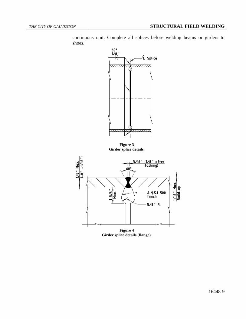
1. Verify that ends of members to be welded are prepared in accordance with the
welded joint detail specified. For girder splices, see Figures 3, 4, and 5 for
proper end preparation and weld details.
2. Bring the parts to be joined by fillet welds into as close contact as possible,
not separated more than 3/16 in. If the separation is 1/16 in. or more, increase
the leg of the fillet weld by the amount of the separation. Keep the separation
between faying surfaces of lap joints and of butt joints landing on backing
strips to no more than 1/16 in.
3. Make suitable allowance for shrinkage, and never restrain the joint on both
sides in any welding process.
4. Use the following fitup procedure for groove welds for butt joints:
a. Align splices of beams and girders joined by groove welds with the
center of gravity of both cross sections coinciding or each flange
vertically offset equally. Fit beams and girders with offset webs with
the webs aligned and the flanges offset laterally. When flanges are
offset or abutting parts differ in thickness or width by more than 1/8
in., make the joint with a smooth transition between offset surfaces
and with a slope of no more than 1:4.
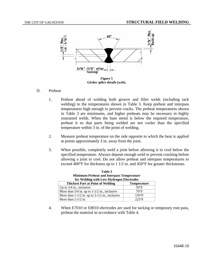
b. Space members to provide a 3/16 in. root opening at the nearest point.
At other points of the joint when the spacing provides up to a 7/16 in.
opening, correction may be made by buildup up to 1/8 in. on each
bevel nose. Rebevel openings exceeding 7/16 in. and move the parts to
be joined closer together to bring the joint within the maximum
buildup limits. Allow buildups to cool to the maximum preheat and
interpass temperatures before welding the joint.
c. Bring all members into correct alignment and hold them in position by
acceptable clamps while welding.
5. Complete all butt splices before welding diaphragms or sway bracing in a
particular section of a unit. Diaphragms and sway bracing may be welded in a
unit behind the splice welding to provide stability except where such welding
interferes with butt splice adjustments, such as at a drop-in segment of a
THE CITY OF GALVESTON STRUCTURAL FIELD WELDING
16448-9
continuous unit. Complete all splices before welding beams or girders to
shoes.
Figure 3
Girder splice details.
Figure 4
Girder splice details (flange).
THE CITY OF GALVESTON STRUCTURAL FIELD WELDING
16448-10
Figure 5
Girder splice details (web).
D. Preheat
1. Preheat ahead of welding both groove and fillet welds (including tack
welding) to the temperatures shown in Table 3. Keep preheat and interpass
temperatures high enough to prevent cracks. The preheat temperatures shown
in Table 3 are minimums, and higher preheats may be necessary in highly
restrained welds. When the base metal is below the required temperature,
preheat it so that parts being welded are not cooler than the specified
temperature within 3 in. of the point of welding.
2. Measure preheat temperature on the side opposite to which the heat is applied
at points approximately 3 in. away from the joint.
3. When possible, completely weld a joint before allowing it to cool below the
specified temperature. Always deposit enough weld to prevent cracking before
allowing a joint to cool. Do not allow preheat and interpass temperatures to
exceed 400°F for thickness up to 1 1/2 in. and 450°F for greater thicknesses.
Table 3
Minimum Preheat and Interpass Temperature
for Welding with Low-Hydrogen Electrodes
Thickest Part at Point of Welding Temperature
Up to 3/4 in., inclusive 50°F
More than 3/4 in. up to 1-1/2 in., inclusive 70°F
More than 1-1/2 in. up to 2-1/2 in., inclusive 150°F
More than 2-1/2 in. 225°F
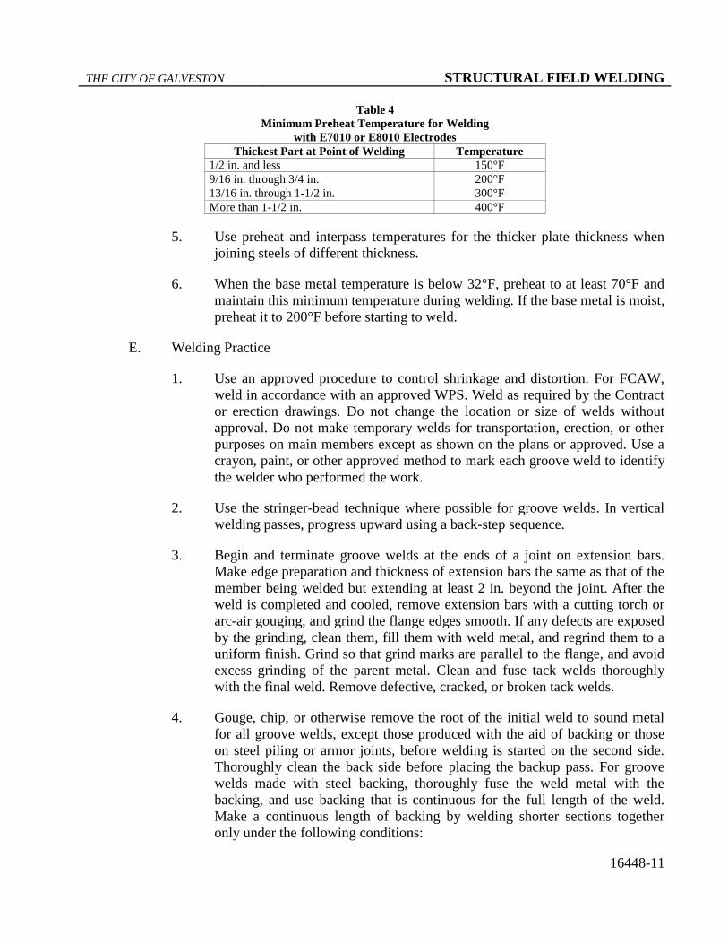
4. When E7010 or E8010 electrodes are used for tacking or temporary root pass,
preheat the material in accordance with Table 4.
THE CITY OF GALVESTON STRUCTURAL FIELD WELDING
16448-11
Table 4
Minimum Preheat Temperature for Welding
with E7010 or E8010 Electrodes
Thickest Part at Point of Welding Temperature
1/2 in. and less 150°F
9/16 in. through 3/4 in. 200°F
13/16 in. through 1-1/2 in. 300°F
More than 1-1/2 in. 400°F
5. Use preheat and interpass temperatures for the thicker plate thickness when
joining steels of different thickness.
6. When the base metal temperature is below 32°F, preheat to at least 70°F and
maintain this minimum temperature during welding. If the base metal is moist,
preheat it to 200°F before starting to weld.
E. Welding Practice
1. Use an approved procedure to control shrinkage and distortion. For FCAW,
weld in accordance with an approved WPS. Weld as required by the Contract
or erection drawings. Do not change the location or size of welds without
approval. Do not make temporary welds for transportation, erection, or other
purposes on main members except as shown on the plans or approved. Use a
crayon, paint, or other approved method to mark each groove weld to identify
the welder who performed the work.
2. Use the stringer-bead technique where possible for groove welds. In vertical
welding passes, progress upward using a back-step sequence.
3. Begin and terminate groove welds at the ends of a joint on extension bars.
Make edge preparation and thickness of extension bars the same as that of the
member being welded but extending at least 2 in. beyond the joint. After the
weld is completed and cooled, remove extension bars with a cutting torch or
arc-air gouging, and grind the flange edges smooth. If any defects are exposed
by the grinding, clean them, fill them with weld metal, and regrind them to a
uniform finish. Grind so that grind marks are parallel to the flange, and avoid
excess grinding of the parent metal. Clean and fuse tack welds thoroughly
with the final weld. Remove defective, cracked, or broken tack welds.
4. Gouge, chip, or otherwise remove the root of the initial weld to sound metal
for all groove welds, except those produced with the aid of backing or those
on steel piling or armor joints, before welding is started on the second side.
Thoroughly clean the back side before placing the backup pass. For groove
welds made with steel backing, thoroughly fuse the weld metal with the
backing, and use backing that is continuous for the full length of the weld.
Make a continuous length of backing by welding shorter sections together
only under the following conditions:
THE CITY OF GALVESTON STRUCTURAL FIELD WELDING
16448-12
All splices in the backing are complete joint penetration (CJP) groove
welds made with the same controls as similar CJP groove welds in the
structure.
The welds are radiographed and examined as described in Section
16448, Part 4, 4.03, G, “Radiographic Inspection,” to ensure weld
soundness.
All welding and testing of the backing is complete before the backing
is used to make the structural weld.
a. High-Cellulose Electrodes for Root Passes
(1). E7010 and E8010 electrodes may be used when welding the
root passes of beam and girder splices if the work is preheated
in accordance with Table 4. After the root passes are backed
up, completely remove the E7010 or E8010 electrode pass by
arc-air gouging, and replace it using a low-hydrogen electrode.
b. Welding Sequence
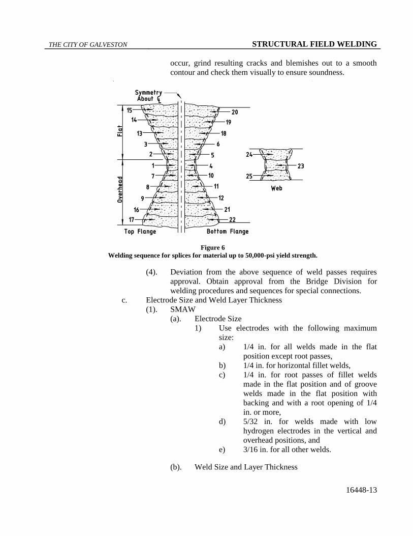
(1). Make beam and girder splices using the sequences shown in
Figure 6. (Some members will require fewer or more passes
than Figure 6 shows.) Alternate welds from flat to overhead to
prevent heat buildup along bevel edge. Arrange the passes
between the top and bottom flange to maintain balance and
symmetry.
(2). For both rolled I beams and built-up girders, place passes 1, 2,
and 3 in the top flange, followed by passes 4, 5, and 6 in the
bottom flange (see Figure 6). Gouge out and replace passes 1
and 4, which always are placed in the overhead position. Next,
place passes 7, 8, and 9 in the top flange, followed by passes
10, 11, and 12 in the bottom flange. Continue with placing
passes 13–17 in the top flange, followed by passes 18–22 in the
bottom flange. Continue to alternate welding between top and
bottom flange with a maximum of 5 passes per flange until the
flange splices are complete. Tack weld web after aligning
girder webs with short tacks as required to obtain proper
alignment. Place pass 23 and pass 24 on the web. Gouge out
and replace pass 23. Finish web splice with pass 25.
(3). For each layer, each bead, and the crater area, remove all slag
and clean the weld and adjacent base metal before welding
over previously deposited metal. Avoid arc strikes, and if they
THE CITY OF GALVESTON STRUCTURAL FIELD WELDING
16448-13
occur, grind resulting cracks and blemishes out to a smooth
contour and check them visually to ensure soundness.
Figure 6
Welding sequence for splices for material up to 50,000-psi yield strength.
(4). Deviation from the above sequence of weld passes requires
approval. Obtain approval from the Bridge Division for
welding procedures and sequences for special connections.
c. Electrode Size and Weld Layer Thickness
(1). SMAW
(a). Electrode Size
1) Use electrodes with the following maximum
size:
a) 1/4 in. for all welds made in the flat
position except root passes,
b) 1/4 in. for horizontal fillet welds,
c) 1/4 in. for root passes of fillet welds
made in the flat position and of groove
welds made in the flat position with
backing and with a root opening of 1/4
in. or more,
d) 5/32 in. for welds made with low
hydrogen electrodes in the vertical and
overhead positions, and
e) 3/16 in. for all other welds.
(b). Weld Size and Layer Thickness
THE CITY OF GALVESTON STRUCTURAL FIELD WELDING
16448-14
1) Make the root pass large enough to prevent
cracking. Make layers subsequent to the root
pass in fillet welds and all layers in groove
welds of the following maximum thickness:
a) 1/4 in. for root passes of groove welds;
b) 1/8 in. for subsequent layers of welds
made in the flat position; and
c) 3/16 in. for subsequent layers of welds
made in the vertical, overhead, and
horizontal positions.
2) Make fillet welds passes no larger than:
a) 3/8 in. in the flat position,
b) 5/16 in. in the horizontal or overhead
positions, and
c) 1/2 in. in the vertical position.
(2). FCAW
(a). Electrode Size
1) Use electrodes with the following maximum
size:
a) 5/32 in. for the flat and horizontal
positions,
b) 3/32 in. for the vertical position, and
c) 5/64 in. for the overhead position.
(b). Weld Size and Layer Thickness
1) Make weld layers, except root and surface
layers, no thicker than 1/4 in. When the root
opening of a groove weld is 1/2 in. or wider, use
a multiple-pass split-layer technique. Use the
split-layer technique to make all multiple-pass
welds when the width of the layer exceeds 5/8
in.
2) Ensure that each pass has complete fusion with
adjacent base metal and weld metal and that
there is no overlap, excessive porosity, or
undercutting.
3) Do not use FCAW with external gas shielding in
a draft or wind. Furnish an approved shelter of
material and shape to reduce wind velocity near
the welding to a maximum of 5 MPH.
THE CITY OF GALVESTON STRUCTURAL FIELD WELDING
16448-15
4) Make fillet weld passes no larger than:
a) 1/2 in. in the flat position,
b) 3/8 in. in the horizontal or overhead
positions, and
c) 5/16 in. in the vertical position.
F. Weld Quality
1. Provide welds that are sound throughout with no cracks in the weld metal or
weld pass. Completely fuse the weld metal and the base metal and each
subsequent pass. Keep welds free from overlap, and keep the base metal free
from undercut more than 1/100 in. deep when the direction of undercut is
transverse to the primary stress in the part that is undercut. Fill all craters to
the full cross section of the welds.
G. Radiographic Inspection
1. Conduct radiographic testing (RT) as required in the field at the expense of
the Contractor by an agency or individual registered and licensed to perform
industrial radiography. Follow all applicable rules and regulations for
radiographic operations. Testing includes furnishing all materials, equipment,
tools, labor, and incidentals necessary to perform the required testing. The
Owner’s Representative may require further tests and may perform additional
testing, including other methods of inspection.
2. Perform RT in accordance with AASHTO/AWS D1.5. The Owner’s
Representative will examine and interpret the resulting radiographs in
accordance with AASHTO/AWS D1.5. All radiographs become the property
of the Owner’s Representative and remain with the Owner’s Representative.
3. For field welds of splices in beams or girders, radiographically inspect the full
flange width of all flange splices and the top and bottom 1/6 of the web at
each splice. Radiographically retest repaired welds. Make necessary repairs
before any further work is done. Additional RT required because of
unacceptable welding or poor radiograph quality is at the Contractor’s
expense. RT of particular welds required by the plans is in addition to the RT
required by this Section.
H. Corrections
1. When welding is unsatisfactory or indicates inferior workmanship, the
Owner’s Representative will require corrective measures and approve the
subsequent corrections.
2. Use oxygen gouging or arc-air gouging when required to remove part of the
weld or base metal. Do not use oxygen gouging on weathering steel.
THE CITY OF GALVESTON STRUCTURAL FIELD WELDING
16448-16
Backgouge splices in beams and girders or cut out defective welds using arc-
air gouging by a welder qualified to make beam and girder splices.
3. Where corrections require depositing additional weld metal, slope the sides of
the area to be welded enough to permit depositing new metal.
4. Where corrections require depositing additional weld metal, use a smaller
electrode than that used for the original weld. Clean surfaces thoroughly
before rewelding.
5. Remove cracked welds completely and repair. If crack length is less than half
the length of the weld, remove the weld metal for the length of the crack plus
2 in. beyond each end of the crack, and repair.
6. Where work performed after making a deficient weld has made the weld
inaccessible or has caused new conditions making the correction of the
deficiency dangerous or ineffectual, restore the original conditions by
removing welds, members, or both before making the necessary corrections;
otherwise, compensate for the deficiency by performing additional work
according to a revised and approved design.
7. Cut apart and reweld improperly fitted or misaligned parts.
8. Straighten members distorted by the heat of welding using mechanical means
or the carefully supervised application of a limited amount of localized heat.
Do not let heated areas exceed 1,200°F as measured by temperature-indicating
crayons or other approved methods for steel up to 65,000 psi yield strength.
Do not let heated areas exceed 1,100°F for higher-strength steels. Keep parts
to be heat-straightened substantially free of stress from external forces except
when mechanical means are used with the application of heat. Before
straightening, submit a straightening procedure to the Owner’s Representative
for approval.
9. Correct defective or unsound welds either by removing and replacing the
entire weld or as follows.
a. Excessive Convexity
(1). Reduce to size by grinding off the excess weld metal, leaving a
smooth profile.
b. Shrinkage Cracks, Cracks in Base Metal, Craters, and Excessive
Porosity
(1). Remove defective portions of base and weld metal down to
sound metal, and replace with additional sound weld metal.
c. Undercut, Undersize, and Excessive Concavity
(1). Clean and deposit additional weld metal.
d. Overlap and Incomplete Fusion
(1). Remove and replace the defective portion of weld.
e. Slag Inclusions
THE CITY OF GALVESTON STRUCTURAL FIELD WELDING
16448-17
(1). Remove the parts of the weld containing slag, and replace them
with sound weld metal.
f. Removal of Base Metal during Welding
(1). Clean and form full size by depositing additional weld metal
using stringer beads.
4.04 WELDING REINFORCING STEEL
A. Splice reinforcing steel by welding only at locations shown on the plans.
1. Base Metal
a. Provide weldable reinforcing steel in conformance with Section
16440, “Reinforcing Steel.”
2. Preheat and Interpass Temperature
a. Minimum preheat and interpass temperatures are shown in Table 5.
When reinforcing steel is below the listed temperature for the size and
carbon equivalency range of the bar being welded, preheat it so that
the cross section of the bar is above the minimum temperature for at
least 6 in. on each side of the joint. After welding is complete, allow
bars to cool naturally to ambient temperature. Do not accelerate
cooling.
Table 5
Minimum Preheat and Interpass Temperature for Reinforcing Steel
Carbon Equivalent
Range (%)
Size of Reinforcing
Bar (no.) Temperature (°F)
Up to and including 0.40 Up to 11 inclusive None
14 and 18 50
0.41 through 0.45
inclusive
Up to 11 inclusive None
14 and 18 100
0.46 through 0.55
inclusive
Up to 6 inclusive None
7 to 11 inclusive 50
14 and 18 200
Unknown Up to 18 inclusive 500
b. For widening projects, base the preheat and interpass temperatures on
the existing reinforcing steel and the requirements of Table 5.
3. Joint Types
a. Use butt splices for all No. 7 and larger bars. Use lap splices for No. 6
and smaller bars.
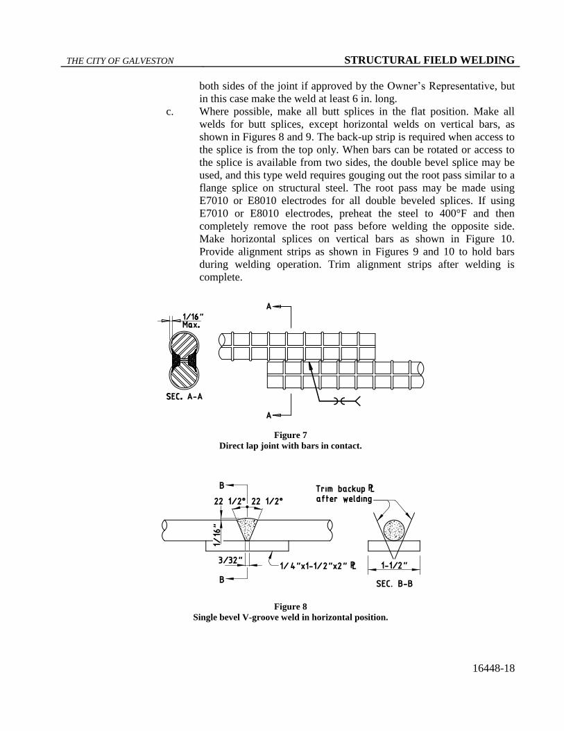
b. Make groove welds in lap splices at least 4 in. long, and weld them on
each side of the lap joint as shown in Figure 7. For No. 5 and smaller
bars, weld from one side of the lap when it is impractical to weld from
THE CITY OF GALVESTON STRUCTURAL FIELD WELDING
16448-18
both sides of the joint if approved by the Owner’s Representative, but
in this case make the weld at least 6 in. long.
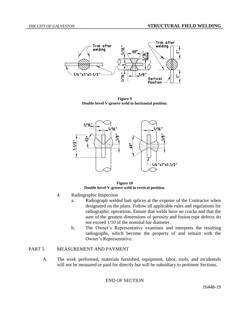
c. Where possible, make all butt splices in the flat position. Make all
welds for butt splices, except horizontal welds on vertical bars, as
shown in Figures 8 and 9. The back-up strip is required when access to
the splice is from the top only. When bars can be rotated or access to
the splice is available from two sides, the double bevel splice may be
used, and this type weld requires gouging out the root pass similar to a
flange splice on structural steel. The root pass may be made using
E7010 or E8010 electrodes for all double beveled splices. If using
E7010 or E8010 electrodes, preheat the steel to 400°F and then
completely remove the root pass before welding the opposite side.
Make horizontal splices on vertical bars as shown in Figure 10.
Provide alignment strips as shown in Figures 9 and 10 to hold bars
during welding operation. Trim alignment strips after welding is
complete.
Figure 7
Direct lap joint with bars in contact.
Figure 8
Single bevel V-groove weld in horizontal position.
THE CITY OF GALVESTON STRUCTURAL FIELD WELDING
16448-19
Figure 9
Double bevel V-groove weld in horizontal position.
Figure 10
Double bevel V-groove weld in vertical position.
4. Radiographic Inspection
a. Radiograph welded butt splices at the expense of the Contractor when
designated on the plans. Follow all applicable rules and regulations for
radiographic operations. Ensure that welds have no cracks and that the
sum of the greatest dimensions of porosity and fusion-type defects do
not exceed 1/10 of the nominal bar diameter.
b. The Owner’s Representative examines and interprets the resulting
radiographs, which become the property of and remain with the
Owner’s Representative.
PART 5 MEASUREMENT AND PAYMENT
A. The work performed, materials furnished, equipment, labor, tools, and incidentals
will not be measured or paid for directly but will be subsidiary to pertinent Sections.
END OF SECTION