Embed Size (px)
Citation preview
Terrain Pleura Alternative engineered drainage ventilation system
PASB2 - PG September 2011
2
Alternative Engineered Ventilation System
• Unique products offering unrivalled installation options
• High quality finish
• Suitable for all types of commercial and residential high-rise
buildings
• Extensive technical experience to support and advise on all
aspects of design and installation
• Fully accredited product systems
As you would expect from a market leader our products come with
all relevant standards including:
Manufacturing Standards BS EN 12380 A1 Air Admittance Valve (Pleura System)
Quality Management Systems Standards
EN ISO 9001:2008 Management System
EN ISO14001:2004 Management System
BS OHSAS 18001:2007 Management System
PASS 99:2006 Integrated Management Registration
Terrain soil & waste products represent the industry benchmark for quality, installation, flexibility and product innovation, backed by the highest levels of customer service. Terrain systems comprise of an extensive range of soil & waste drainage products, including the Terrain Pleura system, a unique alternative ventilation solution for high-rise buildings.
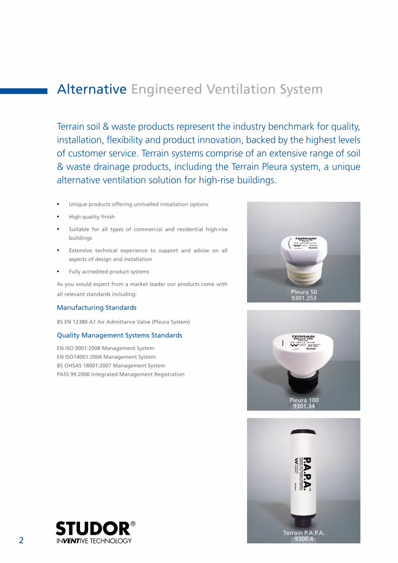
Pleura 509301.253
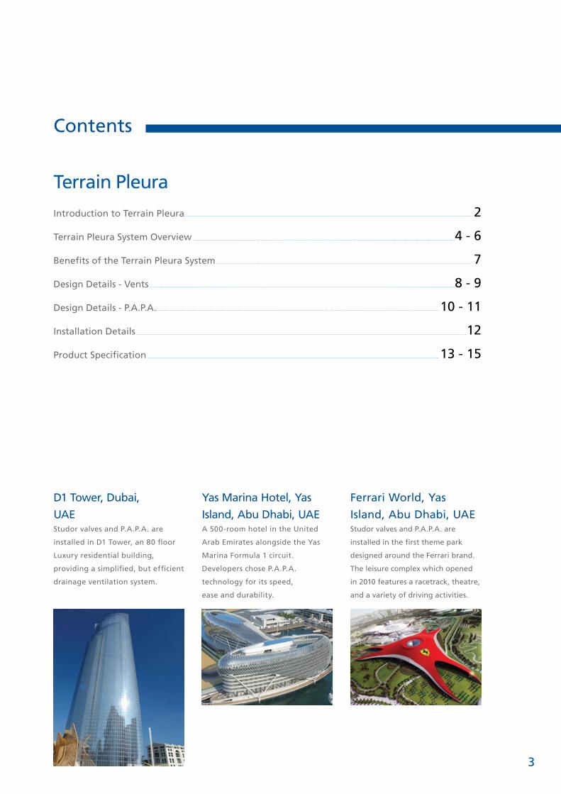
Pleura 1009301.34
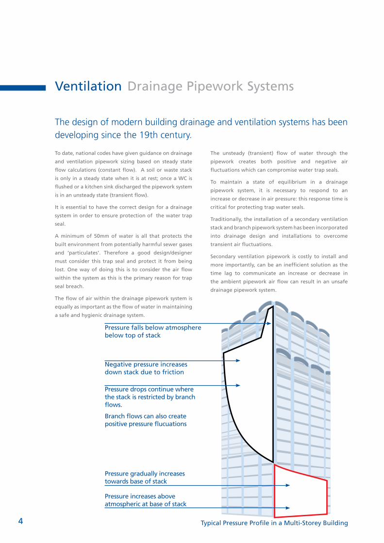
Terrain P.A.P.A.9300.4
3
Contents
Terrain Pleura
Introduction to Terrain Pleura 2
Terrain Pleura System Overview 4 - 6
Benefits of the Terrain Pleura System 7
Design Details - Vents 8 - 9
Design Details - P.A.P.A. 10 - 11
Installation Details 12
Product Specification 13 - 15
Yas Marina Hotel, Yas
Island, Abu Dhabi, UAE
A 500-room hotel in the United
Arab Emirates alongside the Yas
Marina Formula 1 circuit.
Developers chose P.A.P.A.
technology for its speed,
ease and durability.
D1 Tower, Dubai,
UAE
Studor valves and P.A.P.A. are
installed in D1 Tower, an 80 floor
Luxury residential building,
providing a simplified, but efficient
drainage ventilation system.
Ferrari World, Yas
Island, Abu Dhabi, UAE Studor valves and P.A.P.A. are
installed in the first theme park
designed around the Ferrari brand.
The leisure complex which opened
in 2010 features a racetrack, theatre,
and a variety of driving activities.
4
Ventilation Drainage Pipework Systems
The design of modern building drainage and ventilation systems has been developing since the 19th century.
To date, national codes have given guidance on drainage
and ventilation pipework sizing based on steady state
flow calculations (constant flow). A soil or waste stack
is only in a steady state when it is at rest; once a WC is
flushed or a kitchen sink discharged the pipework system
is in an unsteady state (transient flow).
It is essential to have the correct design for a drainage
system in order to ensure protection of the water trap
seal.
A minimum of 50mm of water is all that protects the
built environment from potentially harmful sewer gases
and ‘particulates’. Therefore a good design/designer
must consider this trap seal and protect it from being
lost. One way of doing this is to consider the air flow
within the system as this is the primary reason for trap
seal breach.
The flow of air within the drainage pipework system is
equally as important as the flow of water in maintaining
a safe and hygienic drainage system.
The unsteady (transient) flow of water through the
pipework creates both positive and negative air
fluctuations which can compromise water trap seals.
To maintain a state of equilibrium in a drainage
pipework system, it is necessary to respond to an
increase or decrease in air pressure: this response time is
critical for protecting trap water seals.
Traditionally, the installation of a secondary ventilation
stack and branch pipework system has been incorporated
into drainage design and installations to overcome
transient air fluctuations.
Secondary ventilation pipework is costly to install and
more importantly, can be an inefficient solution as the
time lag to communicate an increase or decrease in
the ambient pipework air flow can result in an unsafe
drainage pipework system.
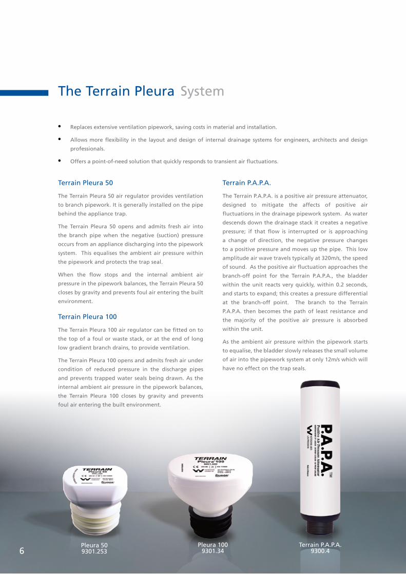
Pressure falls below atmosphere below top of stack
Negative pressure increases down stack due to friction
Pressure drops continue where the stack is restricted by branch flows.
Branch flows can also create positive pressure flucuations
Pressure gradually increases towards base of stack
Pressure increases above atmospheric at base of stack
Typical Pressure Profile in a Multi-Storey Building

5
Following several years of theoretical and practical research at Heriot-Watt University, Edinburgh, Scotland and in partnership with Studor, into both positive and negative transient pressure fluctuations in drainage systems, the Terrain Pleura system provides both an intelligent and integrated solution for balancing the ambient air pressure within a drainage system.
The Terrain Pleura System: how it works.
By removing the secondary ventilation pipework
we can introduce air regulators to balance
negative air pressure fluctuations and an air
attenuator to balance positive pressures.
Together they form a highly effective
alternative solution for maintaining
ambient air pressure within the drainage
pipework system and protecting the
water trap seals of appliances.
The Terrain Pleura Drainage Ventilation System
Pleura 509301.253
Pleura 1009301.34
Terrain P.A.P.A.9300.46
The Terrain Pleura System
Terrain Pleura 50
The Terrain Pleura 50 air regulator provides ventilation
to branch pipework. It is generally installed on the pipe
behind the appliance trap.
The Terrain Pleura 50 opens and admits fresh air into
the branch pipe when the negative (suction) pressure
occurs from an appliance discharging into the pipework
system. This equalises the ambient air pressure within
the pipework and protects the trap seal.
When the flow stops and the internal ambient air
pressure in the pipework balances, the Terrain Pleura 50
closes by gravity and prevents foul air entering the built
environment.
Terrain Pleura 100
The Terrain Pleura 100 air regulator can be fitted on to
the top of a foul or waste stack, or at the end of long
low gradient branch drains, to provide ventilation.
The Terrain Pleura 100 opens and admits fresh air under
condition of reduced pressure in the discharge pipes
and prevents trapped water seals being drawn. As the
internal ambient air pressure in the pipework balances,
the Terrain Pleura 100 closes by gravity and prevents
foul air entering the built environment.
Terrain P.A.P.A.
The Terrain P.A.P.A. is a positive air pressure attenuator,
designed to mitigate the affects of positive air
fluctuations in the drainage pipework system. As water
descends down the drainage stack it creates a negative
pressure; if that flow is interrupted or is approaching
a change of direction, the negative pressure changes
to a positive pressure and moves up the pipe. This low
amplitude air wave travels typically at 320m/s, the speed
of sound. As the positive air fluctuation approaches the
branch-off point for the Terrain P.A.P.A., the bladder
within the unit reacts very quickly, within 0.2 seconds,
and starts to expand; this creates a pressure differential
at the branch-off point. The branch to the Terrain
P.A.P.A. then becomes the path of least resistance and
the majority of the positive air pressure is absorbed
within the unit.
As the ambient air pressure within the pipework starts
to equalise, the bladder slowly releases the small volume
of air into the pipework system at only 12m/s which will
have no effect on the trap seals.
• Replaces extensive ventilation pipework, saving costs in material and installation.
• Allows more flexibility in the layout and design of internal drainage systems for engineers, architects and design
professionals.
• Offers a point-of-need solution that quickly responds to transient air fluctuations.

7
Benefits of the Terrain Pleura System
There are significant benefits to be obtained when incorporating the Terrain Pleura alternative ventilation system:
• Improved control and balancing of air pressures within the drainage pipework system
• Traditional vent pipework requirements are replaced, saving costs in materials, installation, testing and time
• More flexibility during the design process for engineers, architects and design professionals
• Reduced risk through the installation of a fully researched and engineered system that enhances overall performance
to protect water trap seals.
Alternative Engineered Drainage Ventilation Systems
www.polypipegulf.com
ask the experts
Pleura 50
82mmP.A.P.A
Pleura 50
Pleura 50
Pleura 50
82mm
Roof level
Note: Alternative ventilation and termination(No roof level penetration)
Bidet
W.C.LavatoryBasin
Bath / Shower
Sink
Dishwasher
WashingMachine
110mm Soil &Waste Stack
Access
Access
Access82mm
Access
Access
Access
Pleura 50Access
P.A.P.A
Pleura 50
Pleura 50
110mm Waste Pipe
110mm Soil Pipe
Bath / Shower
LavatoryBasin
BidetW.C. Sink
Dishwasher
WashingMachine
Pleura 50
Single Stack
Three Pipe System
110mm Waste and Vent Pipe
110mm Soil and Vent Pipe Vent Pipe
WashingMachine
Dishwasher
Sink
Bath / Shower
LavatoryBasin
BidetW.C.
Three PipeSystem
Two Pipe System

8
Design Details - Vents
There are many design applications that can use Terrain’s Pleura valves. These isometric drawings are intended to show
some of the acceptable applications; however, several alterantives are also acceptable.
COMMON VENT
The common vent serves two or more fixtures. The
Terrain Pleura 50 can be located in close proximity to
the fixtures being vented.
BRANCH VENT
When various vents connect to a branch vent a Terrain
Pleura 50 can serve a replacement for a traditional vent
to the main stack.
STACK VENT
The Terrain Pleura
100 serves as the
vent at a stack. The
maximum height
of the drainage
stack that is
ventilated with
Pleura 100 and
Pleura 50 floors.
WC
50mm
Terrain Pleura 50
Terrain Pleura 50
Terrain Pleura 50
50mm
110mm
50mm
WC
WHB
WHB
WHB
WHB
WHB32mm
Terrain Pleura 50
32mm
50mm
WHB
WHB
WHB
Terrain Pleura 100
Terrain Pleura 50
Terrain Pleura 50
Floor Gully
Floor Gully
50mm
50mm
82mm110mm
110mm
82mm
9
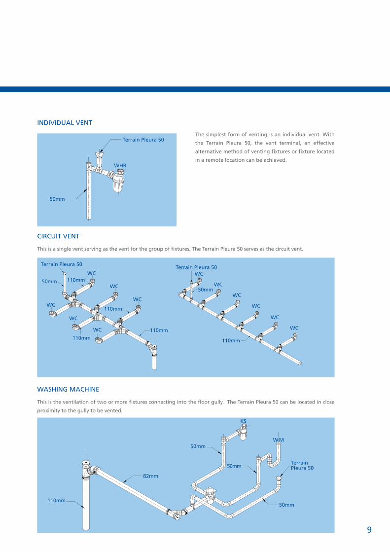
INDIVIDUAL VENT
The simplest form of venting is an individual vent. With
the Terrain Pleura 50, the vent terminal, an effective
alternative method of venting fixtures or fixture located
in a remote location can be achieved.
WASHING MACHINE
This is the ventilation of two or more fixtures connecting into the floor gully. The Terrain Pleura 50 can be located in close
proximity to the gully to be vented.
Terrain Pleura 50
50mm
WHB
Terrain Pleura 50
50mm 110mm
110mm
110mm110mm
WC
WC
WC
WCWC
Terrain Pleura 50
50mm
110mm
WC
WC
WC
WC
WC
WC
WC
CIRCUIT VENT
This is a single vent serving as the vent for the group of fixtures. The Terrain Pleura 50 serves as the circuit vent.
110mm
50mm
KS
WM
50mm
Terrain Pleura 5050mm
82mm
1010
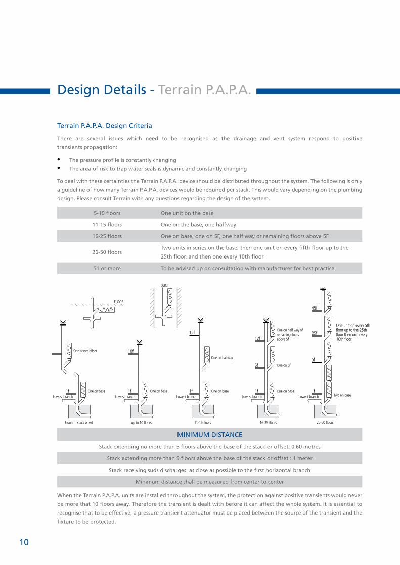
Design Details - Terrain P.A.P.A.
Terrain P.A.P.A. Design Criteria
There are several issues which need to be recognised as the drainage and vent system respond to positive
transients propagation:
• The pressure profile is constantly changing
• The area of risk to trap water seals is dynamic and constantly changing
To deal with these certainties the Terrain P.A.P.A. device should be distributed throughout the system. The following is only
a guideline of how many Terrain P.A.P.A. devices would be required per stack. This would vary depending on the plumbing
design. Please consult Terrain with any questions regarding the design of the system.
5-10 floors One unit on the base
11-15 floors One on the base, one halfway
16-25 floors One on base, one on 5F, one half way or remaining floors above 5F
26-50 floorsTwo units in series on the base, then one unit on every fifth floor up to the
25th floor, and then one every 10th floor
51 or more To be advised up on consultation with manufacturer for best practice
MINIMUM DISTANCE
Stack extending no more than 5 floors above the base of the stack or offset: 0.60 metres
Stack extending more than 5 floors above the base of the stack or offset : 1 meter
Stack receiving suds discharges: as close as possible to the first horizontal branch
Minimum distance shall be measured from center to center
When the Terrain P.A.P.A. units are installed throughout the system, the protection against positive transients would never
be more that 10 floors away. Therefore the transient is dealt with before it can affect the whole system. It is essential to
recognise that to be effective, a pressure transient attenuator must be placed between the source of the transient and the
fixture to be protected.
45f
25f
5f
1f
One unit on every 5th floor up to the 25th floor then one every 10th floor
Lowest branch Two on base
26-50 floors
12f
5f
1fLowest branch
One on base
One on 5f
One on half way ofremaining floorsabove 5f
16-25 floors
12f
1fLowest branch
One on base
One on halfway
11-15 floors
1fLowest branch
One on base
One above offset
Floors + stack offset
10f
1fLowest branch
One on base
up to 10 floors
DUCT
FLOOR

11
The Terrain P.A.P.A. unit is a maintenance free product
and we recommend that it is accessible. Fluids and suds
entering the device will not restrict the device’s ability to
neutralise the negative effects of pressure transients nor
will they compromise the life expectancy of the device.
The use of the Terrain P.A.P.A. devices in conjunction
with Terrain Pleura valves when correctly designed
and installed is necessary to ensure full warranty of the
system.
Terrain Pleura Riser - with Terrain P.A.P.A. device & Pleura Valves
The following standard details have been prepared to
demonstrate Terrain’s recommended installation of its
products. In addition to Terrain recommendations, there
may be other national, state or local specifications that
are pertinent to this application.
Terrain standards do not supersede any national, state
or local specification and Terrain recommends that
those requirements must be reviewed and consulted
with Terrain prior to the installation of Terrain products.
Terrain has not authorised, and it bears no responsibility
for, any revisions, alterations or deviations from this. There
must be a minimum of one vent to open atmosphere per
building system

12
Installation Details
Installation of the Terrain Pleura 50 & 100
• Terrain Pleura valve location must allow for adequate air to enter the valve.
Locating the valve in a sink or vanity cabinet is acceptable.
• The valves must not be located in sealed void or within solid walls.
• Terrain Pleura valves must be accessible.
• Terrain Pleura valves must be installed in a vertical, upright position. A maximum
deviation (in either direction) from plumb of 15 degrees is acceptable.
• Terrain Pleura valves must be located a minimum of 100mm above the
horizontal branch discharge levels.
• The Terrain Pleura 100 must be installed 100mm above the highest flood level
of the fixtures being vented in stack applications.
• A minimum of one vent pipe must be extended to the open atmosphere for
each building drainage system for relief of positive pressure. The size of this
vent is not specified, because this single vent does not determine the total
amount of aggregate cross sectional area of the vent system. The total amount
of the cross sectional area of vents combined on the system must equal the
aggregate cross sectional area of the building drain. When properly installed, a
Terrain Pleura valve in the system is equivalent to an open vent pipe having the
same cross sectional area as any other vent. It is recommended that this kind
of open air vent be located as close as possible to the connection between the
building drain and building sewer.
Installation of the Terrain P.A.P.A.
• The Terrain P.A.P.A. can be connected directly to the 100mm branch bend or
socket by slipping its synthetic rubber connector (provided) onto the fitting.
• The Terrain P.A.P.A. can be installed as a stand-alone unit with and/or without the
Terrain Pleura 100.
• The Terrain P.A.P.A. unit can be mounted vertically or horizontally.
• When mounted vertically (parallel to the waste stack), the P.A.P.A. unit should be
independently supported by an anchor connected to its housing.
• When horizontally mounting the Terrain P.A.P.A. unit, it is advisable to maintain a
minimum of a 10-degree slope so as to induce self-draining.
• When the Terrain P.A.P.A. unit is configured horizontally, the Terrain Pleura 100
vent can be fitted, but the Terrain Pleura 100 vent must be in a vertical position.
Note: The Terrain P.A.P.A. unit does not solve the problem of a slow build-up of pressure
or a sustained positive pressure originating from deposits blocking the pipes, the
blockage of a public sewer, an overloaded septic tank, and so on. This is an inherent
problem that must be resolved with or without the installation of Terrain P.A.P.A. unit(s)
or Terrain valve(s).
Pleura 50
Pleura 100
P.A.P.A.

13
Product Specification
Terrain Pleura 100 - Drainage Ventilation System
The Terrain Pleura 100 is an accepted alterative to replace
all forms of conventional stack venting, using active air
pressure control, and allowing the air to enter the system
at the point of need.
The Terrain Pleura 100 admits air under conditions of
reduced pressure in the discharge pipes and prevents
water seals in traps from being drawn, thus contributing
to the ventilation of the main drain to which the discharge
stacks incorporating the Terrain Pleura 100 are connected.
FEATURES
• Includes screening on the inside and outside of the
Terrain Pleura 100 to protect the sealing membrane
from foreign objects.
• Has a protective cover for the air intake and additional
insulation against extreme temperatures.
• Can divert condensation away from the sealing
membrane.
• Prevents the release of foul air from the drainage
system.
• Available in white ABS.
INSTALLATION
• The Terrain Pleura 100 should be connected to the
piping in accordance with Terrain’s installation
instructions.
WARRANTY
The Terrain Pleura system products have a lifetime
warranty equivalent to that of the drainage system in
which they are installed.
PERFORMANCE PARAMETER
Temperature Range -20O C to +60O C (CE)
-40O F to + 150O F (ASSE)
Open pressure -70 Pa 0.0072
Max. pressure rating Tightness
10,000 Pa (1m/40” H20) at
0Pa or higher
Air flow capacity
Branch Stack
Europe 32l/s 32l/s
AU/NZ 32l/s/1000FU 32l/s/140FU
USA 1 to 160 DFU 72 to 500 DFU
MATERIALS
Pleura 100 Body ABS
Pleura 100 Valve POM
Seal NBR
Internal insulation PEIX
Connector Rubber
PIPE SIZES
Europe AU/NZ USADN 75-110 DN 80-100 3” - 4”
DIMENSIONS - Terrain Pleura 100 Dimensions for line drawings
Dimension Metric (mm)Imperial (Inches)
A 195 7 15⁄16
B 141 5 6⁄8
C 50 2 1⁄16
D 83 3 3⁄8
E 89 3 5⁄8
F 111 4 1⁄2
G 50 2 1⁄16
H 75 3 1⁄16
I 106 4 5⁄16
Pleura 509301.253

1414
Product Specification
Terrain Pleura 50 - Drainage Ventilation System
The Terrain Pleura 50 is an accepted alternative to replace
all forms of conventional branch and stack venting. With
localised active ventilation of the building drainage system
it has been proven that the Terrain Pleura 50 provides
greater protection to prevent induced and self-siphonage
of the fixture traps.
The Terrain Pleura 50 opens and admits fresh air when
the negative (suction) pressure occurs from a fixture
discharging into the system. This equalises the pressure
within the system and protects the trap seal. When
the flow stops, the Terrain Pleura 50 closes by gravity,
preventing any transmission of foul air.
The Terrain Pleura 50 is used as an alternative to extending
the vent pipes through the roof or side wall.
FEATURES
• Includes screening on the inside and outside of the
Terrain Pleura 50 to protect the sealing membrane
from foreign objects.
• Has a protective cover for the air intake and additional
insulation against extreme temperatures.
• Can divert condensation away from the sealing
membrane.
• Prevents the release of foul air from the drainage
system.
• Available in white ABS
INSTALLATION
The Terrain Pleura 50 should be connected to the piping in
accordance with Terrain’s installation instructions.
Refer to you local area regulations for open vent
requirements.
WARRANTY
The Terrain products have a lifetime warranty equivalent
to that of the drainage system in which they are installed.
PIPE SIZES
Europe AU/NZ USADN 32-63 DN 32-63 1 1⁄4” - 2”
DIMENSIONS - Terrain Pleura 50 Dimensions for line drawings
Dimension Metric (mm)Imperial (Inches)
A 195 7 15⁄16
B 141 5 6⁄8
C 50 2 1⁄16
D 81 3 5⁄16
E 73 3
F DN 40 1 1⁄2
G 67 2 3⁄4
H 32 1 5⁄16
I 30 1 4⁄16
J 40 1 5⁄8
K 52 2 1⁄8
PERFORMANCE PARAMETRE
Temperature Range -20O C to +60O C (CE)
-40O F to + 150O F (ASSE)
Open pressure (-70 Pa (-0.010PSI))
Max. pressure rating Tightness
10,000 Pa (1m/40” H20) at
0Pa or higher
Air flow capacity
Branch Stack
Europe (5.7) l/s) (5.7) l/s)
AU/NZ (5.7) l/s/60FU) (5.7) l/s/7FU)
USA 1 to 160 DFU 8 to 24 DFU
MATERIALS
Pleura 50 Body ABS
Pleura 50 Membrane Synthetic Rubber
Global Connector TPE
Pleura 1009301.34
Terrain P.A.P.A 9300.4
15
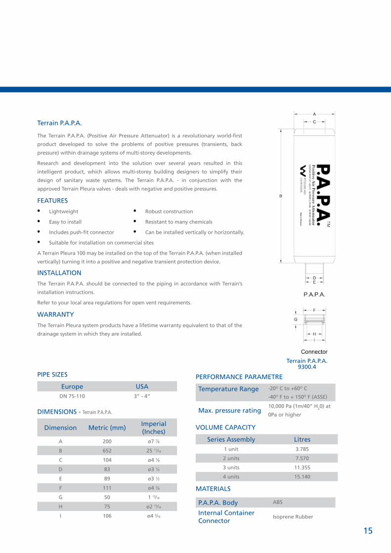
Terrain P.A.P.A.
The Terrain P.A.P.A. (Positive Air Pressure Attenuator) is a revolutionary world-first
product developed to solve the problems of positive pressures (transients, back
pressure) within drainage systems of multi-storey developments.
Research and development into the solution over several years resulted in this
intelligent product, which allows multi-storey building designers to simplify their
design of sanitary waste systems. The Terrain P.A.P.A. - in conjunction with the
approved Terrain Pleura valves - deals with negative and positive pressures.
FEATURES
• Lightweight
• Easy to install
• Includes push-fit connector
• Suitable for installation on commercial sites
A Terrain Pleura 100 may be installed on the top of the Terrain P.A.P.A. (when installed
vertically) turning it into a positive and negative transient protection device.
INSTALLATION
The Terrain P.A.P.A. should be connected to the piping in accordance with Terrain’s
installation instructions.
Refer to your local area regulations for open vent requirements.
WARRANTY
The Terrain Pleura system products have a lifetime warranty equivalent to that of the
drainage system in which they are installed.
PIPE SIZES
Europe USADN 75-110 3” - 4”
DIMENSIONS - Terrain P.A.P.A.
Dimension Metric (mm)Imperial (Inches)
A 200 ø7 7⁄8
B 652 25 11⁄16
C 104 ø4 1⁄8
D 83 ø3 1⁄4
E 89 ø3 1⁄2
F 111 ø4 3⁄8
G 50 1 15⁄16
H 75 ø2 15⁄16
I 106 ø4 3⁄16
PERFORMANCE PARAMETRE
Temperature Range -20O C to +60O C
-40O F to + 150O F (ASSE)
Max. pressure rating 10,000 Pa (1m/40” H20) at
0Pa or higher
VOLUME CAPACITY
Series Assembly Litres1 unit 3.785
2 units 7.570
3 units 11.355
4 units 15.140
MATERIALS
P.A.P.A. Body ABS
Internal Container Connector
Isoprene Rubber
• Robust construction
• Resistant to many chemicals
• Can be installed vertically or horizontally.
Terrain P.A.P.A.9300.4

Terrain Pleura
www.polypipe.com
Polypipe Terrain
New Hythe Business Park
College Road
Aylesford
Kent
ME20 7PJ
United Kingdom
Tel: +44 (0)1622 795200
Fax: +44 (0)1622 716796
www.terraindrainage.com
Polypipe Gulf FZ LLC
Dubai Media City
Loft Office No. 03
Entrance A, 4th Floor
Office no. 404
P.O. Box 502320, Dubai
United Arab Emirates
Tel: +971 (0)4 454 8328
Fax: +971 (0)4 454 2949
www.polypipegulf.com