Embed Size (px)
Citation preview

2/18
Schneider Electric
2
2.2
Contactors
Contactors and reversing contactorstypes LC
p
-K and LP
p
-K
Environment
Conforming to standards
IEC/EN 60947-1, IEC/EN 60947-4-1, NF C 63-110, VDE 0660
Approvals LC
pppp
and LP
pppp
-K06 to K12
UL, CSA, DEMKO, NEMKO, SEMKO, FI
Operating positions Vertical axis Horizontal axis
Without derating Without derating Possible positions for
LC
p
-K
only. Contactor energisation voltage: 0.85 Uc
Max to
Cabling
Min Max IEC/EN 60947Screw clamp connections Solid conductor
mm
2
1 x 1.5 2 x 4 1 x 4 + 1 x 2.5
Flexible cable without cable end
mm
2
1 x 0.75 2 x 4 2 x 2.5
Flexible cable with cable end
mm
2
1 x 0.34 1 x 1.5 + 1 x 2.5 1 x 1.5 + 1 x 2.5
Spring terminal connections Solid conductor
mm
2
1 x 0.75 1 x 1.5 2 x 1.5Flexible conductor without cable end
mm
2
1 x 0.75 1 x 1.5 2 x 1.5
Faston connectors Clip
mm
2 x 2.8 or 1 x 6.35
Solder pins for With locating device between powerprinted circuit board and control circuits 4 mm x 35 microns
Tightening torque
Philips head n˚ 2 and Ø 6
N.m
0.8…1.3
Terminal referencing
Conforming to standards EN 50005 and EN 50012 Up to 5 contacts
Rated insulation voltage
(Ui) Conforming to IEC/EN 60947-4-1
V
690
Conforming to VDE 0110 gr C
V
750
Conforming to NF C 20-040
V
690
Conforming to CSA 22-2 n˚ 14, UL 508
V
600
Rated impulse withstand voltage
(Uimp)
kV
8
Protective treatment
Conforming to IEC 68 (DIN 50016) “TC” (Klimafest, Climateproof)
Degree of protection
Conforming to VDE 0106 Protection against direct finger contact
Ambient air temperature
Storage
˚C
- 50…+ 80around the device
Operation
˚C
- 25…+ 50
Maximum operating altitude
Without derating
m
2000
Vibration resistance
Contactor open 2 gn5 ... 300 Hz
Contactor closed 4 gn
Flame resistance
Conforming to UL 94 Self-extinguishing materials V1
Conforming to NF F 16-101 and 16-102 Conforming to requirement 2
Shock resistance
Contactor open 10 g(1/2 sine wave, 11 ms)
Contactor closed 15 g
Safe circuit separation
Conforming to VDE 0106 and IEC 536 VLSV (Very Low Safety voltage), up to 400 V
Characteristics
Selection:pages 1/12 to 1/35
References:pages 2/22 to 2/35
Dimensions:pages 2/40 and 2/42
Schemes:pages 2/41 and 2/43
°180
°
22005_Ver8.00-EN.backup.fm Page 18 Thursday, October 25, 2001 4:59 PM

2/19
Schneider Electric
2
2.2
Contactors
Contactors and reversing contactorstypes LC
p
-K and LP
p
-K
Pole characteristics
Conventional thermal current
(Ith) For ambient temperature
≤
50 ˚C
A
20
Rated operational frequency Hz
50/60
Frequency limits ofoperational current Hz
Up to 400
Rated operational voltage
(Ue)
V
690
Rated making capacity
I rms to NF C 63-110 and IEC/EN 60947-4-1
LC
pppp
-K06, LP
pppp
-K06, LC
pppp
-K09, LP
pppp
-K09
A
110
LC
pppp
-K12, LP
pppp
-K12
A
144
Rated breaking capacity V
220/ 380/ 415 440 500 660/240 400 690
I rms to NF C 63-110 and IEC/EN 60947-4-1
LC
pppp
-K06, LP
pppp
-K06, LC
pppp
-K09, LP
pppp
-K09 A
110 110 110 110 80 70
LC
pppp
-K12, LP
pppp
-K12 A
– – – 110 80 70
Permissible short time rating
In free air for a time “t” 1 s 5 s 10 s 30 s
1 min
3 min
≥
15 min
from cold state (
θ ≤
50 ˚C)
LC
pppp
-K06, LP
pppp
-K06, LC
pppp
-K09, LP
pppp
-K09 A
90 85 80 60 45 40 20
LC
pppp
-K12, LP
pppp
-K12 A
115 105 100 75 55 50 25
Short-circuit protection
gG fuse U
≤
440 V (aM fuse, see page
2/46
)
A
25
Average impedance per pole
At Ith and 50 Hz
m
Ω
3
Utilisation in category AC-1
Maximum rated operational current
A
20resistive circuits, heating, lighting for a temperature
≤
50 ˚C(Ue
≤
440 V)Maximum rated operational current
A
16 for Ue onlyfor a temperature
≤
70 ˚C
Rated operational current limits in relation
A
On-load factor 90% 60 % 30 %to on-load factor and operating frequency
300 op. cycles/hour 13 15 18
120 op. cycles/hour 15 18 19
30 op. cycles/hour 19 20 20
Increase in operational current Apply the following coefficients to the current valuesby paralleling of poles above. These take into account the often
unbalanced current distribution between poles
2 poles in parallel: K = 1.60
3 poles in parallel: K = 2.25
4 poles in parallel: K = 2.80
Utilisation in category AC-3
Operational powersquirrel cage motors according to the voltage Voltage 50 or 60 Hz
V
115 220 220/ 380/ 440/ 500/ 660/240 415 480 600 690
1-ph 1-ph 3-ph 3-ph 3-ph 3-ph 3-ph
LC
pppp
-K06, LP
pppp
-K06 kW
0.37 0.75 1.5 2.2 3 3 3
LC
pppp
-K09, LP
pppp
-K09 kW
0.55 1.1 2.2 4 4 4 4
LC
pppp
-K12, LP
pppp
-K12 kW
– – 3 5.5
5.5/
4 4
4 (480)
% utilisation of operational power in relation Op. cycles/hr 600 900 1200to the maximum operating rate
Power 100% 75% 50%
Characteristics
Selection:pages 1/12 to 1/35
References:pages 2/22 to 2/35
Dimensions:pages 2/40 and 2/42
Schemes:pages 2/41 and 2/43
22005_Ver8.00-EN.backup.fm Page 19 Thursday, October 25, 2001 4:59 PM

2/20
Schneider Electric
2
2.2
Contactors
Contactors and reversing contactorstypes LC
p
-K and LP
p
-K
(1) For mains supplies with a high level of interference (voltage surge > 800 V), use a suppressor module LA4-KE1FC(50…129 V) or LAF-KE1UG (130…250 V), see page 2/38.
Control circuit characteristics
Contactor type LC1 LC2 LC7 LC8 LP1 LP2
Rated control circuit voltage
(Uc)
V
a
12…690 (1)
a
24…240
c
12…250 (1)
Control voltage limits
Operation 0.8…1.15 Uc 0.85…1.1 Uc 0.8…1.15 Uc(
≤
50 ˚C) single voltage coil
Drop-out
≥
0.20 Uc
≥
0.10 Uc
≥
0.10 Uc
Average consumption
Inrush 30 VA 3 VA 3 Wat 20 ˚C and at Uc
Sealed 4.5 VA 3 VA 3 W
Heat dissipation W
1.3 3 3
Operating time
Between coil energisation and:at 20 ˚C and at Uc - opening of the N/C contacts
ms
5…15 25…35 25…35- closing of the N/O contacts
ms
10…20 30…40 30…40
Between coil de-energisation and:- opening of the N/O contacts
ms
10…20 30 10- closing of the N/C contacts
ms
15…25 40 15
Maximum immunity tomicro-breaks ms
2 2 2
Maximum operating rate
In operating cycles per hour 3600 3600 3600
Mechanical durability at Uc
50/60 Hz coil 10 5 10 5 – –In millions of operating cycles
c
coil – – – – 10 5
Characteristics
(continued)
Selection:pages 1/12 to 1/35
References:pages 2/22 to 2/35
Dimensions:pages 2/40 and 2/42
Schemes:pages 2/41 and 2/43
22005_Ver8.00-EN.backup.fm Page 20 Thursday, October 25, 2001 5:00 PM

2/21
Schneider Electric
2
2.2
10 000
5000
3000
2000
1000800600500400300
200
1008060
24 48 110 220
440 690 V120
380 50040
16 000
80006000
4000
2c2b
4
1
2a
1000
700
500
300
200
1008060504030
20
1086
12 24 48 110 220 440 600 V
250
200
140
100
50
20
2c
2b
2a
3
4
Characteristics of contactor auxiliary contacts and instantaneous contact blocks
Number of auxiliary contacts
On
LC
p
-K
or
LP
p
-K
1
On
LA1-K
2 or 4
Rated operational voltage
(Ue) Up to
V
690
Rated insulation voltage
(Ui) Conforming to IEC/EN 60947-4-1
V
690
Conforming to VDE 0110 group C
V
750
Conforming to CSA C 22-2 n˚ 14
V
600
Conventional thermal current
(lth) For ambient temperature
≤
50 ˚C
A
10
Frequency of operational current Hz
Up to 400
Minimum switching capacity
U min (DIN 19 240)
V
17 (2 < 10
-3
)
I min
mA
5
Short-circuit protection
Conforming to IEC/EN 60947-4-1 and VDE 0660,
A
10gG fuse
Rated making capacity
Conforming to IEC/EN 60947-4-1 I rms
A
110
Overload current
Permissible for 1 s
A
80
500 ms
A
90
100 ms
A
110
Insulation resistance M
Ω
> 10
Non-overlap distance LA1-K:
linked contacts to INRS, BIA and CNA specs.
mm
0.5 (see schemes, pages 2/41 and 2/43)
Operational power of contacts a.c. supply, category AC-15 d.c. supply, category DC-13
conforming to IEC/EN 60947 Electrical durability (valid up to 3600 operating cyclesper hour) on an inductive load such as the coil of anelectromagnet: making current (cos
ϕ
0.7) = 10 times the breaking current (cos
ϕ
0.4).
1 million operating cycles3 million operating cycles10 million operating cyclesOccasional making capacity
1 Breaking limit of contacts valid for:- maximum of 50 operating cyclesat 10 s intervals(breaking current = making currentx cos
ϕ
0.7).
2 Electrical durability of contacts for:- 1 million operating cycles (
2a
)-3 million operating cycles (
2b
)-10 million operating cycles (
2c
).
3 Breaking limit of contacts valid for:- maximum of 20 operating cyclesat 10 s intervals with current passingfor 0.5 s per operating cycle.
4 Thermal limit.
Contactors
Contactors and reversing contactorstypes LC
p
-K and LP
p
-K
Characteristics
Selection:pages 1/12 to 1/35
References:pages 2/22 to 2/35
Dimensions:pages 2/40 and 2/42
Schemes:pages 2/41 and 2/43
110/ 220/ 380/ 600/V 24 48 127 230 400 440 690VA
48 96 240 440 800 880 1200
VA
17 34 86 158 288 317 500
VA
7 14 36 66 120 132 200
VA
1000 2050 5000 10 000 14 000 13 000 9000
Electrical durability (valid up to 1200 operating cycles perhour), on an inductive load such as the coil of an electro-magnet, without economy resistor, the time constantincreasing with the load.
V 24 48 110 220 440 600W
120 80 60 52 51 50
W
55 38 30 28 26 25
W
15 11 9 8 7 6
W
720 600 400 300 230 200
Tim
e co
nsta
ntin
mill
isec
onds
Power broken in VA Power broken in W
22005_Ver8.00-EN.backup.fm Page 21 Thursday, October 25, 2001 5:00 PM
2/22
Schneider Electric
2
2.2
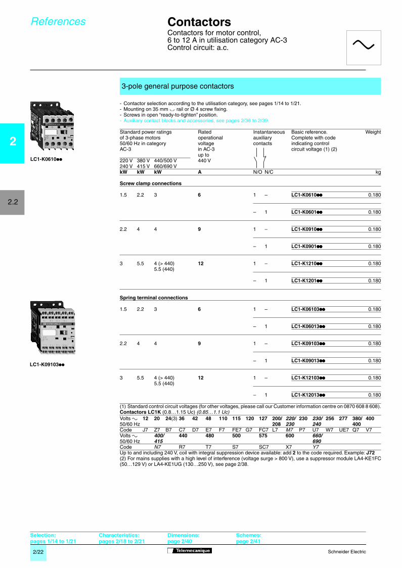
- Contactor selection according to the utilisation category, see pages
1/14 to 1/21
.- Mounting on 35 mm
7
rail or Ø 4 screw fixing.- Screws in open “ready-to-tighten” position.- Auxiliary contact blocks and accessories, see pages 2/36 to 2/39.
(1) Standard control circuit voltages (for other voltages, please call our Customer information centre on 0870 608 8 608).
Contactors LC1K
(0.8…1.15 Uc)
(0.85…1.1 Uc)
Up to and including 240 V, coil with integral suppression device available: add
2
to the code required. Example:
J72
(2) For mains supplies with a high level of interference (voltage surge > 800 V), use a suppressor module LA4-KE1FC(50…129 V) or LA4-KE1UG (130…250 V), see page
2/38
.
3-pole general purpose contactors
Standard power ratings Rated Instantaneous Basic reference. Weightof 3-phase motors operational auxiliary Complete with code50/60 Hz in category voltage contacts indicating controlAC-3 in AC-3 circuit voltage (1) (2)
up to220 V 380 V 440/500 V 440 V240 V 415 V 660/690 V
kW kW kW A
N/O N/C kg
Screw clamp connections
1.5 2.2 3
6
1 –
LC1-K0610
pppppppp
0.180
– 1
LC1-K0601
pppppppp
0.180
2.2 4 4
9
1 –
LC1-K0910
pppppppp
0.180
– 1
LC1-K0901
pppppppp
0.180
3 5.5 4 (> 440)
12
1 –
LC1-K1210
pppppppp
0.1805.5 (440)
– 1
LC1-K1201
pppppppp
0.180
Spring terminal connections
1.5 2.2 3
6
1 –
LC1-K06103
pppppppp
0.180
– 1
LC1-K06013
pppppppp
0.180
2.2 4 4
9
1 –
LC1-K09103
pppppppp
0.180
– 1
LC1-K09013
pppppppp
0.180
3 5.5 4 (> 440)
12
1 –
LC1-K12103
pppppppp
0.1805.5 (440)
– 1
LC1-K12013
pppppppp
0.180
Volts
a
12 20 24
(3)
36 42 48 110 115 120 127 200/
220/
230
230/
256 277 380/ 400
50/60 Hz
208
230 240
400
Code J7 Z7 B7 C7 D7 E7 F7 FE7 G7 FC7 L7
M7
P7 U7 W7 UE7 Q7 V7Volts
a
400/
440 480 500 575 600
660/
50/60 Hz
415 690
Code
N7
R7 T7 S7 SC7 X7
Y7
Contactors
Contactors for motor control, 6 to 12 A in utilisation category AC-3 Control circuit: a.c.
References
LC1-K0610
pp
Selection: pages 1/14 to 1/21
Characteristics: pages 2/18 to 2/21
Dimensions:page 2/40
Schemes:page 2/41
a
LC1-K09103
pp
22006_Ver7.00-EN.backup.fm Page 22 Thursday, October 25, 2001 5:01 PM

2/23
Schneider Electric
2
2.2
- Contactor selection according to the utilisation category, see pages
1/14 to 1/21
.- Mounting on 35 mm
7
rail or Ø 4 screw fixing.- Screws in open “ready-to-tighten” position.- Auxiliary contact blocks and accessories, see pages
2/36 to 2/39.
(1) Standard control circuit voltages (for other voltages, please call our Customer information centre on 0870 608 8 608).
Contactors LC1K
(0.8…1.15 Uc)
(0.85…1.1 Uc)
Up to and including 240 V, coil with integral suppression device available: add
2
to the code required. Example:
J72
(2) For mains supplies with a high level of interference (voltage surge > 800 V), use a suppressor module LA4-KE1FC(50…129 V) or LA4-KE1UG (130…250 V), see page
2/38
.
3-pole general purpose contactors
Standard power ratings Rated
Instantaneous
Basic reference. Weightof 3-phase motors operational auxiliary Complete with code50/60 Hz in category voltage contacts indicating controlAC-3 in AC-3 circuit voltage (1) (2)
up to220 V 380 V 440/500 V 440 V240 V 415 V 660/690 V
kW kW kW A
N/O N/C kg
Faston connectors, 1 x 6.35 or 2 x 2.8
1.5 2.2 3
6
1 –
LC1-K06107
pppppppp
0.180
– 1
LC1-K06017
pppppppp
0.180
2.2 4 4
9
1 –
LC1-K09107
pppppppp
0.180
– 1
LC1-K09017
pppppppp
0.180
3 5.5 4 (> 440)
12
1 –
LC1-K12107
pppppppp
0.1805.5 (440)
– 1
LC1-K12017
pppppppp
0.180
Solder pins for printed circuit boards
1.5 2.2 3
6
1 –
LC1-K06105
pppppppp
0.210
– 1
LC1-K06015
pppppppp
0.210
2.2 4 4
9
1 –
LC1-K09105
pppppppp
0.210
– 1
LC1-K09015
pppppppp
0.210
3 5.5 4 (> 440)
12
1 –
LC1-K12105
pppppppp
0.2105.5 (440)
– 1
LC1-K12015
pppppppp
0.210
Volts
a
12 20 24
(3)
36 42 48 110 115 120 127 200/
220/
230
230/
256 277
380/
400
50/60 Hz
208
230 240 400
Code J7 Z7 B7 C7 D7 E7 F7 FE7 G7 FC7 L7
M7
P7
U7
W7 UE7
Q7
V7Volts
a
400/
440 480 500 575 600
660/
50/60 Hz
415 690
Code
N7
R7 T7 S7 SC7 X7
Y7
Contactors
Contactors for motor control, 6 to 12 A in utilisation category AC-3Control circuit: a.c.
References
LC1-K06107
pp
LC1-K06105
pp
Selection: pages 1/14 to 1/21
Characteristics: pages 2/18 to 2/21
Dimensions:page 2/40
Schemes:page 2/41
a
22006_Ver7.00-EN.backup.fm Page 23 Thursday, October 25, 2001 5:01 PM

2/24
Schneider Electric
2
2.2
Contactors
Contactors for motor control, 6 to 12 A in utilisation category AC-3 Control circuit: a.c.
Recommended for use in areas sensitive to noise, high interference mains supplies, etc.
- Contactor selection according to utilisation category, see pages
1/14 to 1/21
.- Coil with rectifier incorporated, suppressor fitted as standard.- Mounting on 35 mm
7
rail or Ø 4 screw fixing.- Screws in open “ready-to-tighten” position.- Auxiliary contact blocks and accessories, see pages
2/36
to 2/39.
(1) Standard control circuit voltages (for other voltages, please call our Customer information centre on 0870 608 8 608).
Contactors LC7-K
(0.85…1.1 Uc)
(2) For mains supplies with a high level of interference (voltage surge > 800 V), use a suppressor module LA4-KE1FC(50…129 V) or LA4-KE1UG (130…250 V), see page
2/38
.
3-pole contactors for use in sensitive environments
Standard power ratings Rated
Instantaneous
Basic reference. Weightof 3-phase motors opera- auxiliary Complete with code50/60 Hz in category tional contacts indicating controlAC-3 current circuit voltage (1) (2)
in AC-3220 V 380 V 440/500 V up to240 V 415 V 660/690 V 440 V
kW kW kW A
N/O N/C kg
Screw clamp connections
1.5 2.2 3
6
1 –
LC7-K0610
pppppppp
0.225
– 1
LC7-K0601
pppppppp
0.225
2.2 4 4
9
1 –
LC7-K0910
pppppppp
0.225
– 1
LC7-K0901
pppppppp
0.225
3 5.5 4 (> 440)
12
1 –
LC7-K1210
pppppppp
0.2255.5 (440)
– 1
LC7-K1201
pppppppp
0.225
Faston connectors, 1 x 6.35 or 2 x 2.8
1.5 2.2 3
6
1 –
LC7-K06107
pppppppp
0.225
– 1
LC7-K06017
pppppppp
0.225
2.2 4 4
9
1 –
LC7-K09107
pppppppp
0.225
– 1
LC7-K09017
pppppppp
0.225
3 5.5 4 (> 440)
12
1 –
LC7-K12107
pppppppp
0.2255.5 (440)
– 1
LC7-K12017
pppppppp
0.225
Solder pins for printed circuit boards
1.5 2.2 3
6
1 –
LC7-K06105
pppppppp
0.255
– 1
LC7-K06015
pppppppp
0.255
2.2 4 4
9
1 –
LC7-K09105
pppppppp
0.255
– 1
LC7-K09015
pppppppp
0.255
3 5.5 4 (> 440)
12
1 –
LC7-K12105
pppppppp
0.2555.5 (440)
– 1
LC7-K12015
pppppppp
0.255
Volts
a
24 42 48 110 115 220 230/
50/60 Hz
240
Code B7 D7 E7 F7 FE7 M7 U7
References
(continued)
LC7-K06105
pp
Selection: pages 1/14 to 1/21
Characteristics: pages 2/18 to 2/21
Dimensions:page 2/40
Schemes:page 2/41
a
22006_Ver7.00-EN.backup.fm Page 24 Thursday, October 25, 2001 5:02 PM

2/25
Schneider Electric
2
2.2
- Contactor selection according to the utilisation category, see pages
1/14 to 1/21
.- Mounting on 35 mm
7
rail or Ø 4 screw fixing.- Screws in open “ready-to-tighten” position.- Auxiliary contact blocks and accessories, see pages
2/36 to 2/39
.
(1) Standard control circuit voltages (for other voltages, please call our Customer information centre on 0870 608 8 608).
Contactors LP1-K
(0.8…1.15 Uc)
Coil with suppression device available: add
3
to the code required. Example:
JD3.
(2) When connecting an electronic sensor or timer in series with the coil of the contactor, select a 20 V coil (
a
controlcircuit voltage code Z7,
c
control circuit voltage code ZD) so as to compensate for the incurred voltage drop.
3-pole contactors
Standard power ratings Rated
Instantaneous
Basic reference. Weightof 3-phase motors operational auxiliary Complete with code50/60 Hz in category voltage contacts indicating controlAC-3 in AC-3 circuit voltage (1)
up to220 V 380 V 440/500 V 440 V240 V 415 V 660/690 V
kW kW kW A
N/O N/C kg
Screw clamp connections
1.5 2.2 3
6
1 –
LP1-K0610
pppppppp
0.225
– 1
LP1-K0601
pppppppp
0.225
2.2 4 4
9
1 –
LP1-K0910
pppppppp
0.225
– 1
LP1-K0901
pppppppp
0.225
3 5.5 4 (> 440 V)
12
1 –
LP1-K1210
pppppppp
0.2255.5 (440 V)
– 1
LP1-K1201
pppppppp
0.225
Spring terminal connections
1.5 2.2 3
6
1 –
LP1-K06103
pppppppp
0.225
– 1
LP1-K06013
pppppppp
0.225
2.2 4 4
9
1 –
LP1-K09103
pppppppp
0.225
– 1
LP1-K09013
pppppppp
0.225
3 5.5 4 (> 440 V)
12
1 –
LP1-K12103
pppppppp
0.2255.5 (440 V)
– 1
LP1-K12013
pppppppp
0.225
Faston connectors, 1 x 6.35 or 2 x 2.8
1.5 2.2 3
6
1 –
LP1-K06107
pppppppp
0.225
– 1
LP1-K06017
pppppppp
0.225
2.2 4 4
9
1 –
LP1-K09107
pppppppp
0.225
– 1
LP1-K09017
pppppppp
0.225
3 5.5 4 (> 440 V)
12
1 –
LP1-K12107
pppppppp
0.2255.5 (440 V)
– 1
LP1-K12017
pppppppp
0.225
Solder pins for printed circuit boards
1.5 2.2 3
6
1 –
LP1-K06105
pppppppp
0.255
– 1
LP1-K06015
pppppppp
0.255
2.2 4 4
9
1 –
LP1-K09105
pppppppp
0.255
– 1
LP1-K09015
pppppppp
0.255
3 5.5 4 (> 440 V)
12
1 –
LP1-K12105
pppppppp
0.2555.5 (440 V)
– 1
LP1-K12015
pp
0.255
Volts
c
12 20 24
(2)
36 48 60 72 100 110 125 155 174 200 220 230 240 250
Code JD ZD BD CD ED ND SD KD FD GD PD QD LD MD MPD MUD UD
Contactors
Contactors for motor control, 6 to 12 A in utilisation category AC-3Control circuit: d.c.
References
LP1-K0610
pp
LP1-K06107
pp
Selection: pages 1/14 to 1/21
Characteristics: pages 2/18 to 2/21
Dimensions:page 2/40
Schemes:page 2/41
c
22006_Ver7.00-EN.backup.fm Page 25 Thursday, October 25, 2001 5:02 PM

Schneider Electric2/26
2
2.2
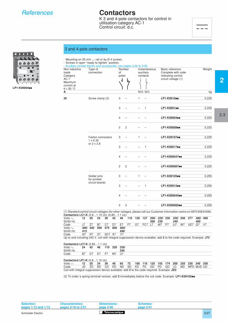
General purpose contactors
- Mounting on 35 mm " rail or by Ø 4 screws.- Screws in open “ready-to-tighten” position.- Auxiliary contact blocks and accessories, see pages 2/36 to 2/39.Non inductive Type of Number Instantaneous Basic reference. Weightloads connection of auxiliary Complete with codeCategory poles contacts indicating controlAC-1 circuit voltage (1)Maximumcurrent atθ ≤ 50 °C
A N/O N/C kg
20 Screw clamp (2) 3 – 1 – LC1-K0910ii 0.225
3 – – 1 LC1-K0901ii 0.225
4 – – – LC1-K09004ii 0.180
2 2 – – LC1-K09008ii 0.180
Faston connectors 3 – 1 – LC1-K09107ii 0.2251 x 6.35or 2 x 2.8 3 – – 1 LC1-K09017ii 0.225
4 – – – LC1-K090047ii 0.180
2 2 – – LC1-K090087ii 0.180
Solder pins 3 – 1 – LC1-K09105ii 0.255for printedcircuit boards 3 – – 1 LC1-K09015ii 0.255
4 – – – LC1-K090045ii 0.210
2 2 – – LC1-K090085ii 0.210
Contactors for use in sensitive environments
Recommended for use in areas sensitive to noise, high interference mains supplies, etc.
- Coil with rectifier incorporated, suppressor fitted as standard.- Mounting on 35 mm " rail or Ø 4 screw fixing.- Screws in open “ready-to-tighten” position.- Auxiliary contact blocks and accessories, see pages 2/36 to 2/39.
20 Screw clamp (2) 3 – 1 – LC7-K0910ii 0.225
3 – – 1 LC7-K0901ii 0.225
4 – – – LC7-K09004ii 0.225
2 2 – – LC7-K09008ii 0.225
Faston connectors 3 – 1 – LC7-K09107ii 0.2251 x 6.35or 2 x 2.8 3 – – 1 LC7-K09017ii 0.225
4 – – – LC7-K090047ii 0.225
2 2 – – LC7-K090087ii 0.225
Solder pins 3 – 1 – LC7-K09105ii 0.255for printedcircuit boards 3 – – 1 LC7-K09015ii 0.255
4 – – – LC7-K090045ii 0.255
2 2 – – LC7-K090085ii 0.255(1) Standard control circuit voltages, see page opposite.(2) To order a spring terminal version, add 3 immediately before the coil code. Example: LC1-K09103ii.
Selection: Characteristics: Dimensions: Schemes:pages 1/12 and 1/13 pages 2/18 to 2/21 page 2/40 page 2/41
ContactorsK 3 and 4-pole contactors for control inutilisation category AC-1Control circuit: a.c.
References
LC1-K09004ii
LC7-K090047ii
a
2/026 - 2/027 25/10/01, 11:54 am2
Schneider Electric 2/27
2
ContactorsK 3 and 4-pole contactors for control inutilisation category AC-1Control circuit: d.c.
References
3 and 4-pole contactors
- Mounting on 35 mm " rail or by Ø 4 screws.- Screws in open “ready-to-tighten” position.- Auxiliary contact blocks and accessories, see pages 2/36 to 2/39.Non inductive Type of Number Instantaneous Basic reference. Weightloads connection of auxiliary Complete with codeCategory poles contacts indicating controlAC-1 circuit voltage (1)Maximumcurrent atθ ≤ 50 °CA N/O N/C kg
20 Screw clamp (2) 3 – 1 – LP1-K0910ii 0.225
3 – – 1 LP1-K0901ii 0.225
4 – – – LP1-K09004ii 0.225
2 2 – – LP1-K09008ii 0.225
Faston connectors 3 – 1 – LP1-K09107ii 0.2251 x 6.35or 2 x 2.8
3 – – 1 LP1-K09017ii 0.225
4 – – – LP1-K090047ii 0.225
2 2 – – LP1-K090087ii 0.225
Solder pins 3 – 1 – LP1-K09105ii 0.255for printedcircuit boards
3 – – 1 LP1-K09015ii 0.255
4 – – – LP1-K090045ii 0.255
2 2 – – LP1-K090085ii 0.255
(1) Standard control circuit voltages (for other voltages, please call our Customer information centre on 0870 608 8 608).Contactors LC1-K (0.8…1.15 Uc) (0.85…1.1 Uc)Volts c 12 20 24 36 42 48 110 120 127 200/ 220/ 230 230/ 256 277 380/ 40050/60 Hz 208 230 240 400Code J7 Z7 B7 C7 D7 E7 F7 G7 FC7 L7 M7 P7 U7 W7 UE7 Q7 V7Volts c 400/ 440 500 575 600 660/50/60 Hz 415 690Code N7 R7 S7 SC7 X7 Y7Up to and including 240 V, coil with integral suppression device available: add 2 to the code required. Example: J72
Contactors LC7-K (0.85…1.1 Uc)Volts c 24 42 48 110 220 230/50/60 Hz 240Code B7 D7 E7 F7 M7 U7
Contactors LP1-K (0.8…1.15 Uc)Volts a 12 20 24 36 48 60 72 100 110 125 155 174 200 220 230 240 250Code JD ZD BD CD ED ND SD KD FD GD PD QD LD MD MPD MUD UDCoil with integral suppression device available: add 3 to the code required. Example: JD3
(2) To order a spring terminal version, add 3 immediately before the coil code. Example: LP1-K09103ii.
LP1-K09004ii
Selection: Characteristics: Dimensions: Schemes:pages 1/12 and 1/13 pages 2/18 to 2/21 page 2/40 page 2/41
c
2.3
2/026 - 2/027 25/10/01, 11:55 am3

2/28
Schneider Electric
2
2.2
Contactors
Reversing contactors for motor control 6 to 12 A in utilisation category AC-3 Control circuit: a.c.
- Reversing contactor selection according to utilisation category, see pages
1/14 to 1/21
.- Integral mechanical interlock.
It is essential to link the contacts of the electrical interlock.
- Pre-wired power circuit connections as standard on screw clamp versions.- Mounting on 35 mm
7
or Ø 4 mm screw fixing.- Screws in open “ready-to-tighten” position.- Auxiliary contact blocks and accessories, see pages
2/36 to 2/39
.
(1) Standard control circuit voltages (for other voltages, please call our Customer information centre on 0870 608 8 608).
Reversing contactors LC2-K
(0.8…1.15 Uc) (
0.85…1.1 Uc
)
Up to and including 240 V, coil with integral suppression device available: add
2
to the code required. Example:
J72
(2) For mains supplies with a high level of interference (voltage surge > 800 V), use a suppressor module LA4-KE1FC(50…129 V) or LA4-KE1UG (130…250 V), see page
2/38
.
3-pole general purpose reversing contactors
Standard power ratings Rated Instantan. Basic reference. Weightof 3-phase motors operational auxiliary Complete with code50/60 Hz in category current contacts indicating controlAC-3 in AC-3 circuit voltage (1) (2)
up to220 V 380 V 440/500 V 400 V240 V 415 V 660/690 V
kW kW kW A
N/O N/C kg
Screw clamp connections
1.5 2.2 3
6
1 –
LC2-K0610
pppppppp
0.390
– 1
LC2-K0601
pppppppp
0.390
2.2 4 4
9
1 –
LC2-K0910
pppppppp
0.390
– 1
LC2-K0901
pppppppp
0.390
3 5.5 4 (> 440)
12
1 –
LC2-K1210
pppppppp
0.3905.5 (440)
– 1
LC2-K1201
pppppppp
0.390
Spring terminal connections
1.5 2.2 3
6
1 –
LC2-K06103
pppppppp
0.430
– 1
LC2-K06013
pppppppp
0.430
2.2 4 4
9
1 –
LC2-K09103
pppppppp
0.430
– 1
LC2-K09013
pppppppp
0.430
3 5.5 4 (> 440)
12
1 –
LC2-K12103
pppppppp
0.4305.5 (440)
– 1
LC2-K12013
pppppppp
0.430
Volts
a
12 20 24 36 42 48 110 115 120 127 200/ 220/ 230 230/ 256 277 380/ 400
50/60 Hz
208 230 240 400
Code J7 Z7 B7 C7 D7 E7 F7 FE7 G7 FC7 L7
M7
P7
U7
W7 UE7
Q7
V7Volts
a
400/ 440 480 500 575 600
660/
50/60 Hz
415
690
Code N7 R7 T7 S7 SC7 X7
Y7
References
LC2-K0610
pp
Selection: pages 1/14 to 1/21
Characteristics: pages 2/18 to 2/21
Dimensions: page 2/42
Schemes:page 2/43
a
22016_Ver6.00-EN.fm Page 28 Thursday, October 25, 2001 5:03 PM

2/29
Schneider Electric
2
2.2
Contactors
Reversing contactors for motor control 6 to 12 A in utilisation category AC-3 Control circuit: a.c.
- Reversing contactor selection according to utilisation category, see pages
1/14 to 1/21
.- Integral mechanical interlock.
It is essential to link the contacts of the electrical interlock.
- Pre-wired power circuit connections as standard on screw clamp versions.- Mounting on 35 mm
7
or Ø 4 mm screw fixing.- Screws in open “ready-to-tighten” position.- Auxiliary contact blocks and accessories, see pages
2/36
to
2/39
.
(1) Standard control circuit voltages (for other voltages, please call our Customer information centre on 0870 608 8 608).
Reversing contactors LC2-K
(0.8…1.15 Uc) (
0.85…1.1 Uc
)
Up to and including 240 V, coil with integral suppression device available: add
2
to the code required. Example:
J72
(2) For mains supplies with a high level of interference (voltage surge > 800 V), use a suppressor module LA4-KE1FC(50…129 V) or LA4-KE1UG (130…250 V), see page
2/38
.
3-pole general purpose reversing contactors
Standard power ratings Rated Instantan. Basic reference. Weightof 3-phase motors operational auxiliary Complete with code50/60 Hz in category current contacts indicating controlAC-3 in AC-3 circuit voltage (1) (2)
up to220 V 380 V 440/500 V 400 V240 V 415 V 660/690 V
kW kW kW A
N/O N/C kg
Faston connectors, 1 x 6.35 or 2 x 2.8
1.5 2.2 3
6
1 –
LC2-K06107
pppppppp
0.370
– 1
LC2-K06017
pppppppp
0.370
2.2 4 4
9
1 –
LC2-K09107
pppppppp
0.370
– 1
LC2-K09017
pppppppp
0.370
3 5.5 4 (> 440)
12
1 –
LC2-K12107
pppppppp
0.3705.5 (440)
– 1
LC2-K12017
pppppppp
0.370
Solder pins for printed circuit boards
1.5 2.2 3
6
1 –
LC2-K06105
pppppppp
0.430
– 1
LC2-K06015
pppppppp
0.430
2.2 4 4
9
1 –
LC2-K09105
pppppppp
0.430
– 1
LC2-K09015
pppppppp
0.430
3 5.5 4 (> 440)
12
1 –
LC2-K12105
pppppppp
0.4305.5 (440)
– 1
LC2-K12015
pppppppp
0.430
Volts
a
12 20 24 36 42 48 110 115 120 127 200/
220/
230
230/
256 277
380/
400
50/60 Hz
208
230 240 400
Code J7 Z7 B7 C7 D7 E7 F7 FE7 G7 FC7 L7
M7
P7
U7
W7 UE7
Q7
V7Volts
a
400/
440 480 500 575 600
660/
50/60 Hz
415 690
Code
N7
R7 T7 S7 SC7 X7
Y7
References
Selection: pages 1/14 to 1/21
Characteristics: pages 2/18 to 2/21
Dimensions: page 2/42
Schemes:page 2/43
a
LC2-K06107
pp
22016_Ver6.00-EN.fm Page 29 Thursday, October 25, 2001 5:04 PM

2/30
Schneider Electric
2
2.2
Contactors
Reversing contactors for motor control 6 to 12 A in utilisation category AC-3 Control circuit: a.c.
Recommended for use in areas sensitive to noise, high interference mains supplies, etc.
- Reversing contactor selection according to utilisation category, see pages
1/14 to 1/21
.- Coil with rectifier incorporated, suppressor fitted as standard.- Integral mechanical interlock.
It is essential to link the contacts of the electrical interlock.
- Pre-wired power circuit connections as standard on screw clamp versions.- Mounting on
7
35 mm rail or Ø 4 mm screw fixing.- Screws in open, “ready-to-tighten” position.- Auxiliary contact blocks and accessories, see pages
2/36
to
2/39
.
(1) Standard control circuit voltages (for other voltages, please call our Customer information centre on 0870 608 8 608).
Reversing contactors LC8-K
(0.85…1.1 Uc)
(2) For mains supplies with a high level of interference (voltage surge > 800 V), use a suppressor module LA4-KE1FC(50…129 V) or LA4-KE1UG (130…250 V), see page
2/38
.
3-pole reversing contactors for use in sensitive environments
Standard power ratings Rated Instantan. Basic reference. Weightof 3-phase motors operational auxiliary Complete with code50/60 Hz in category current contacts indicating controlAC-3 in AC-3 circuit voltage (1) (2)
up to220 V 380 V 440/500 V 400 V240 V 415 V 660/690 V
kW kW kW A
N/O N/C kg
Screw clamp connections
1.5 2.2 3
6
1 –
LC8-K0610
pppppppp
0.480
– 1
LC8-K0601
pppppppp
0.480
2.2 4 4
9
1 –
LC8-K0910
pppppppp
0.480
– 1
LC8-K0901
pppppppp
0.480
3 5.5 4 (> 440)
12
1 –
LC8-K1210
pppppppp
0.4805.5 (440
– 1
LC8-K1201
pppppppp
0.480
Faston connectors 1 x 6.35 or 2 x 2.8
1.5 2.2 3
6
1 –
LC8-K06107
pppppppp
0.460
– 1
LC8-K06017
pppppppp
0.460
2.2 4 4
9
1 –
LC8-K09107
pppppppp
0.460
– 1
LC8-K09017
pppppppp
0.460
3 5.5 4 (> 440)
12
1 –
LC8-K12107
pppppppp
0.4605.5 (440)
– 1
LC8-K12017
pppppppp
0.460
Solder pins for printed circuit boards
1.5 2.2 3
6
1 –
LC8-K06105
pppppppp
0.520
– 1
LC8-K06015
pppppppp
0.520
2.2 4 4
9
1 –
LC8-K09105
pppppppp
0.520
– 1
LC8-K09015
pppppppp
0.520
3 5.5 4 (> 440)
12
1 –
LC8-K12105
pppppppp
0.5205.5 (440)
– 1
LC8-K12015
pppppppp
0.520
Volts
a
24 42 48 110 115 220 230/
50/60 Hz
240
Code B7 D7 E7 F7 FE7 M7 U7
References
(continued)
LC8-K06105
pp
Selection: pages 1/14 to 1/21
Characteristics: pages 2/18 to 2/21
Dimensions: page 2/42
Schemes:page 2/43
a
22016_Ver6.00-EN.fm Page 30 Thursday, October 25, 2001 5:05 PM

2/31
Schneider Electric
2
2.2
Contactors
Reversing contactors for motor control6 to 12 A in utilisation category AC-3Control circuit: d.c.
- Contactor selection according to utilisation category, see pages
1/14 to 1/21
.- Integral mechanical interlock.
It is essential to link the contacts of the electrical interlock.
- Pre-wired power circuit connections as standard on screw clamp versions.- Mounting on 35 mm
7
or Ø 4 mm screw fixing.- Screws in open “ready-to-tighten” position.- Auxiliary contact blocks and accessories, see pages
2/36
to
2/39
.
Spring terminal connections
Faston connectors, 1 x 6.35 or 2 x 2.8
Solder pins for printed circuit boards
(1)
Standard control circuit voltages (for other voltages, please call our Customer information centre on 0870 608 8 608).
Reversing contactors LP2-K
(0.8…1.15 Uc)
Coil with integral suppression device available: add
3
to the code required. Example:
JD3.
(2) When connecting an electronic sensor or timer in series with the coil of the contactor, select a 20 V coil (
a
controlcircuit voltage code Z7,
c
control circuit voltage code ZD) so as to compensate for the incurred voltage drop.
3-pole reversing contactors
Standard power ratings Rated Instantan. Basic reference. Weightof 3-phase motors operational auxiliary Complete with code50/60 Hz in category current contacts indicating controlAC-3 in AC-3 circuit voltage (1) (2)
up to220 V 380 V 440/500 V 400 V240 V 415 V 660/690 V
kW kW kW A
N/O N/C kg
Screw clamp connections
1.5 2.2 3
6
1 –
LP2-K0610
pppppppp
0.480– 1
LP2-K0601
pppppppp
0.480
2.2 4 4
9
1 –
LP2-K0910
pppppppp
0.480– 1
LP2-K0901
pppppppp
0.480
3 5.5 4 (> 440)
12
1 –
LP2-K1210
pppppppp
0.4805.5 (440) – 1
LP2-K1201
pppppppp
0.480
1.5 2.2 3
6
1 –
LP2-K06103
pppppppp
0.520– 1
LP2-K06013
pppppppp
0.520
2.2 4 4
9
1 –
LP2-K09105
pppppppp
0.520– 1
LP2-K09015
pppppppp
0.520
3 5.5 4 (> 440)
12
1 –
LP2-K12105
pppppppp
0.5205.5 (440) – 1
LP2-K12015
pppppppp
0.520
1.5 2.2 3
6
1 –
LP2-K06107
pppppppp
0.460– 1
LP2-K06017
pppppppp
0.460
2.2 4 4
9
1 –
LP2-K09107
pppppppp
0.460– 1
LP2-K09017
pppppppp
0.460
3 5.5 4 (> 440)
12
1 –
LP2-K12107
pppppppp
0.4605.5 (440) – 1
LP2-K12017
pppppppp
0.460
1.5 2.2 3
6
1 –
LP2-K06105
pppppppp
0.520– 1
LP2-K06015
pppppppp
0.520
2.2 4 4
9
1 –
LP2-K09105
pppppppp
0.520– 1
LP2-K09015
pppppppp
0.520
3 5.5 4 (> 440)
12
1 –
LP2-K12105
pppppppp
0.5205.5 (440) – 1
LP2-K12015
pppppppp
0.520
Volts
c
12 20 24 36 48 60 72 100 110 125 155 174 200 220 230 240 250
Code JD ZD BD CD ED ND SD KD FD GD PD QD LD MD MPD MUD UD
References
LP2-K0610
pp
LP2-K06107
pp
Selection: pages 1/14 to 1/21
Characteristics: pages 2/18 to 2/21
Dimensions: page 2/42
Schemes:page 2/43
c
22016_Ver6.00-EN.fm Page 31 Thursday, October 25, 2001 5:06 PM

2/32
Schneider Electric
2
2.2
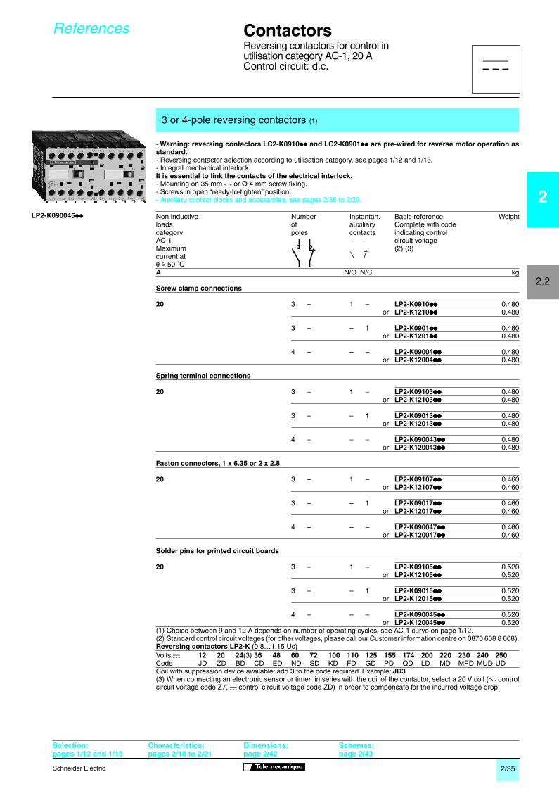
-
Warning: reversing contactors LC2-K0910
pp
and LC2-K0901
pp
are pre-wired for reverse motor operation asstandard.
- Reversing contactor selection according to utilisation category, see pages
1/12 and 1/13
.- Integral mechanical interlock.
It is essential to link the contacts of the electrical interlock.
- Mounting on 35 mm
7
or Ø 4 mm screw fixing.- Screws in open “ready-to-tighten” position.- Auxiliary contact blocks and accessories, see pages
2/36 to 2/39
.
(1) Choice between 9 and 12 A depends on number of operating cycles, see AC-1 curve on page
1/12
.
(2) Standard control circuit voltages (for other voltages, please call our Customer information centre on 0870 608 8 608).
Reversing contactors LC2-K
(0.8…1.15 Uc)
(0.85…1.1 Uc)
Up to and including 240 V, coil with integral suppression device available: add
2
to the code required. Example:
J72
(3) For mains supplies with a high level of interference (voltage surge > 800 V), use a suppressor module LA4-KE1FC(50…129 V) or LA4-KE1UG (130…250 V), see page
2/38
.
3 or 4-pole general purpose reversing contactors
(1)
Non inductive Number Instantan. Basic reference. Weightloads of auxiliary Complete with codecategory poles contacts indicating controlAC-1 circuit voltageMaximum (2) current at
θ
≤
50 ˚C
A
N/O N/C kg
Screw clamp connections
20
3 – 1 –
LC2-K0910
pppppppp
0.390
or
LC2-K1210
pppppppp
0.390
3 – – 1
LC2-K0901
pppppppp
0.390
or
LC2-K1201
pppppppp
0.390
4 – – –
LC2-K09004
pppppppp
0.380
or
LC2-K12004
pppppppp
0.380
Spring terminal connections
20
3 – 1 –
LC2-K09103
pppppppp
0.390
or
LC2-K12103
pppppppp
0.390
3 – – 1
LC2-K09013
pppppppp
0.390
or
LC2-K12013
pppppppp
0.390
4 – – –
LC2-K090043
pppppppp
0.380
or
LC2-K120043
pppppppp
0.380
Volts
a
12 20 24
(3)
36 42 48 110 115 120 127 200/
220/
230
230/
256 277
380/
400
50/60 Hz
208
230 240 400
Code J7 Z7 B7 C7 D7 E7 F7 FE7 G7 FC7 L7 M7 P7
U7
W7 UE7 Q7 V7Volts
a
400/
440 480 500 575 600
660/
50/60 Hz
415 690
Code
N7
R7 T7 S7 SC7 X7
Y7
Contactors
Reversing contactors for control in utilisation category AC-1, 20 AControl circuit: a.c.
References
Selection:pages 1/12 and 1/13
Characteristics:pages 2/18 to 2/21
Dimensions:page 2/42
Schemes:page 2/43
a
LC2-K0910
pppppppp
22017_Ver5.00-EN.fm Page 32 Thursday, October 25, 2001 5:07 PM

2/33
Schneider Electric
2
2.2
-
Warning: reversing contactors LC2-K0910
pp
and LC2-K0901
pp
are pre-wired for reverse motor operation asstandard.
- Reversing contactor selection according to utilisation category, see pages
1/12 and 1/13
.- Integral mechanical interlock.
It is essential to link the contacts of the electrical interlock.
- Mounting on 35 mm
7
or Ø 4 mm screw fixing.- Screws in open “ready-to-tighten” position.- Auxiliary contact blocks and accessories, see pages
2/36 to 2/39
.
(1) Choice between 9 and 12 A depends on number of operating cycles, see AC-1 curve on page
1/12
.
(2) Standard control circuit voltages (for other voltages, please call our Customer information centre on 0870 608 8 608).
Reversing contactors LC2-K
(0.8…1.15 Uc)
(0.85…1.1 Uc)
Up to and including 240 V, coil with integral suppression device available: add
2
to the code required. Example:
J72
(3) For mains supplies with a high level of interference (voltage surge > 800 V), use a suppressor module LA4-KE1FC(50…129 V) or LA4-KE1UG (130…250 V), see page
2/38
.
3 or 4-pole general purpose reversing contactors
(1)
Non inductive Number Instantan. Basic reference. Weightloads of auxiliary Complete with codecategory poles contacts indicating controlAC-1 circuit voltageMaximum (2)current at
θ
≤
50 ˚C
A
N/O N/C kg
Faston connectors, 1 x 6.35 or 2 x 2.8
20
3 – 1 –
LC2-K09107
pppppppp
0.370
or
LC2-K12107
pppppppp
0.370
3 – – 1
LC2-K09017
pppppppp
0.370
or
LC2-K12017
pppppppp
0.370
4 – – –
LC2-K090047
pppppppp
0.370
or
LC2-K120047
pppppppp
0.370
Solder pins for printed circuit boards
20
3 – 1 –
LC2-K09105
pppppppp
0.430
or
LC2-K12105
pppppppp
0.430
3 – – 1
LC2-K09015
pppppppp
0.430
or
LC2-K12015
pppppppp
0.430
4 – – –
LC2-K090045
pppppppp
0.430
or
LC2-K120045
pppppppp
0.430
Volts
a
12 20 24
(3)
36 42 48 110 115 120 127 200/
220/
230
230/
256 277
380/
400
50/60 Hz
208
230 240 400
Code J7 Z7 B7 C7 D7 E7 F7 FE7 G7 FC7 L7
M7
P7
U7
W7 UE7
Q7
V7Volts
a
400/
440 480 500 575 600
660/
50/60 Hz
415 690
Code
N7
R7 T7 S7 SC7 X7
Y7
Contactors
Reversing contactors for control in utilisation category AC-1, 20 AControl circuit: a.c.
References
Selection:pages 1/12 and 1/13
Characteristics:pages 2/18 to 2/21
Dimensions:page 2/42
Schemes:page 2/43
LC2-K090045
pp
a
22017_Ver5.00-EN.fm Page 33 Thursday, October 25, 2001 5:07 PM

2/34
Schneider Electric
2
2.2
Recommended for use in areas sensitive to noise, high interference mains supplies, etc.
-
Warning: reversing contactors LC2-K0910
pp
and LC2-K0901
pp
are pre-wired for reverse motor operation asstandard.
- Reversing contactor selection according to utilisation category, see pages
1/12 and 1/13
.- Integral mechanical interlock.
It is essential to link the contacts of the electrical interlock.
- Mounting on 35 mm
7
or Ø 4 mm screw fixing.- Screws in open “ready-to-tighten” position.- Auxiliary contact blocks and accessories, see pages
2/36 to 2/39
.
(1) Choice between 9 and 12 A depends on number of operating cycles, see AC-1 curve on page
1/12
.
(2) Standard control circuit voltages (for other voltages, please call our Customer information centre on 0870 608 8 608).
Reversing contactors LC8-K
(0.85…1.1 Uc): coil with integral rectifier and suppression device as standard.
(3) For mains supplies with a high level of interference (voltage surge > 800 V), use a suppressor module LA4-KE1FC(50…129 V) or LA4-KE1UG (130…250 V), see page
2/38
.
3 or 4-pole reversing contactors for use in sensitive environments
(1)
Non inductive Number Instantan. Basic reference.
Weight
loads of auxiliary Complete with codecategory poles contacts indicating controlAC-1 circuit voltageMaximum (2) (3)current at
θ ≤
50 ˚C
A
N/O N/C kg
Screw clamp connections
20
3 – 1 –
LC8-K0910
pppppppp
0.480
or
LC8-K1210
pppppppp
0.480
3 – – 1
LC8-K0901
pppppppp
0.480
or
LC8-K1201
pppppppp
0.480
4 – – –
LC8-K09004
pppppppp
0.470
or
LC8-K12004
pppppppp
0.470
Faston connectors, 1 x 6.35 or 2 x 2.8
20
3 – 1 –
LC8-K09107
pppppppp
0.460
or
LC8-K12107
pppppppp
0.460
3 – – 1
LC8-K09017
pppppppp
0.460
or
LC8-K12017
pppppppp
0.460
4 – – –
LC8-K090047
pppppppp
0.460
or
LC8-K120047
pppppppp
0.460
Solder pins for printed circuit boards
20
3 – 1 –
LC8-K09105
pppppppp
0.520
or
LC8-K12105
pppppppp
0.520
3 – – 1
LC8-K09015
pppppppp
0.520
or
LC8-K12015
pppppppp
0.520
4 – – –
LC8-K090045
pppppppp
0.520
or
LC8-K120045
pppppppp
0.520
Volts
a
24 42 48 110 115 220 230/
50/60 Hz
240
Code B7 D7 E7 F7 FE7 M7 U7
Contactors
Reversing contactors for control in utilisation category AC-1, 20 AControl circuit: a.c.
References
(continued)
Selection:pages 1/12 and 1/13
Characteristics:pages 2/18 to 2/21
Dimensions:page 2/42
Schemes:page 2/43
LC8-K09105
pp
a
22017_Ver5.00-EN.fm Page 34 Thursday, October 25, 2001 5:07 PM
2/35
Schneider Electric
2
2.2
-
Warning: reversing contactors LC2-K0910
pp
and LC2-K0901
pp
are pre-wired for reverse motor operation asstandard.
- Reversing contactor selection according to utilisation category, see pages
1/12 and 1/13
.- Integral mechanical interlock.
It is essential to link the contacts of the electrical interlock.
- Mounting on 35 mm
7
or Ø 4 mm screw fixing.- Screws in open “ready-to-tighten” position.- Auxiliary contact blocks and accessories, see pages
2/36
to
2/39
.
(1) Choice between 9 and 12 A depends on number of operating cycles, see AC-1 curve on page
1/12
.
(2) Standard control circuit voltages (for other voltages, please call our Customer information centre on 0870 608 8 608).
Reversing contactors LP2-K
(0.8…1.15 Uc)
Coil with suppression device available: add
3
to the code required. Example:
JD3
(3) When connecting an electronic sensor or timer in series with the coil of the contactor, select a 20 V coil (
a
controlcircuit voltage code Z7,
c
control circuit voltage code ZD) in order to compensate for the incurred voltage drop
3 or 4-pole reversing contactors
(1)
Non inductive Number Instantan. Basic reference. Weightloads of auxiliary Complete with codecategory poles contacts indicating controlAC-1 circuit voltageMaximum (2) (3)current at
θ
≤
50 ˚C
A
N/O N/C kg
Screw clamp connections
20
3 – 1 –
LP2-K0910
pppppppp
0.480or
LP2-K1210
pppppppp
0.480
3 – – 1
LP2-K0901
pppppppp
0.480or
LP2-K1201
pppppppp
0.480
4 – – –
LP2-K09004
pppppppp
0.480or
LP2-K12004
pppppppp
0.480
Spring terminal connections
20
3 – 1 –
LP2-K09103
pppppppp
0.480or
LP2-K12103
pppppppp
0.480
3 – – 1
LP2-K09013
pppppppp
0.480or
LP2-K12013
pppppppp
0.480
4 – – –
LP2-K090043
pppppppp
0.480or
LP2-K120043
pppppppp
0.480
Faston connectors, 1 x 6.35 or 2 x 2.8
20
3 – 1 –
LP2-K09107
pppppppp
0.460or
LP2-K12107
pppppppp
0.460
3 – – 1
LP2-K09017
pppppppp
0.460or
LP2-K12017
pppppppp
0.460
4 – – –
LP2-K090047
pppppppp
0.460or
LP2-K120047
pppppppp
0.460
Solder pins for printed circuit boards
20
3 – 1 –
LP2-K09105
pppppppp
0.520or
LP2-K12105
pppppppp
0.520
3 – – 1
LP2-K09015
pppppppp
0.520or
LP2-K12015
pppppppp
0.520
4 – – –
LP2-K090045
pppppppp
0.520or
LP2-K120045
pppppppp
0.520
Volts
c
12 20 24
(3)
36 48 60 72 100 110 125 155 174 200 220 230 240 250
Code JD ZD BD CD ED ND SD KD FD GD PD QD LD MD MPD MUD UD
Contactors
Reversing contactors for control inutilisation category AC-1, 20 AControl circuit: d.c.
References
Selection:pages 1/12 and 1/13
Characteristics:pages 2/18 to 2/21
Dimensions:page 2/42
Schemes:page 2/43
LP2-K090045
pp
c
22017_Ver5.00-EN.fm Page 35 Thursday, October 25, 2001 5:08 PM
2/36
Schneider Electric
2
2.2
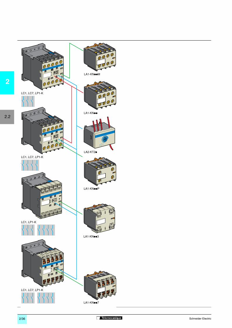
LC1, LC7, LP1-K
LC1, LC7, LP1-K
LC1, LC7, LP1-K
LC1, LP1-K
22014_Ver4.00-EN.fm Page 36 Thursday, October 25, 2001 5:10 PM

2/37
Schneider Electric
2
2.2
Recommended for standard applications. Clip-on front mounting, 1 block per contactor
- Relay output, with common point changeover contact,
a
or
c
240 V, 2 A maximum.- Control voltage: 0.85…1.1 Uc.- Maximum switching capacity: 250 VA or 150 W.- Operating temperature: -10…+ 60 ˚C.
- Reset time: 1.5 s during the time delay period, 0.5 s after the time delay period.
Clip-on front mounting, 1 block per contactor
Instantaneous auxiliary contact blocks
Type of connection For use with Composition Reference Weightcontactors
N/O N/C kg
Screw clamp
LC1, LC2 2 –
LA1-KN20
0.045LC7, LC8 – 2
LA1-KN02
0.045LP1, LP2 1 1
LA1-KN11
0.0453 or 4-pole 4 –
LA1-KN40
0.0453 1
LA1-KN31
0.0452 2
LA1-KN22
0.0451 3
LA1-KN13
0.045– 4
LA1-KN04
0.045
Spring terminal
LC1, LC2, 2 –
LA1-KN203
0,045LP1, LP2 – 2
LA1-KN023
0,0453 or 4-pole 1 1
LA1-KN113
0.0454 –
LA1-KN403
0.0453 1
LA1-KN313
0.0452 2
LA1-KN223
0.0451 3
LA1-KN133
0.045– 4
LA1-KN043
0.045
Faston
LC1, LC2 2 –
LA1-KN207
0.045
1 x 6.35
LC7, LC8 – 2
LA1-KN027
0.045
or 2 x 2.8
LP1, LP2 1 1
LA1-KN117
0.0453 or 4-pole 4 –
LA1-KN407
0.0453 1
LA1-KN317
0.0452 2
LA1-KN227
0.0451 3
LA1-KN137
0.045– 4
LA1-KN047
0.045
With terminal referencing conforming to standard EN 50012. Clip-on front mounting, 1 block per contactor
Screw clamp
LC1, LC2 – 2
LA1-KN02M
0.045
with terminal
LC7, LC8 1 1
LA1-KN11M
0.045
referencing
LP1, LP2 3 1
LA1-KN31M
0.045
conforming to
3-pole + N/O 2 2
LA1-KN22M
0.045
standard EN 50012
1 3
LA1-KN13M
0.045
LC1, LC2 1 1
LA1-KN11P
0.045LC7, LC8LP1, LP24-pole 2 2
LA1-KN22P
0.045
Electronic time delay auxiliary contact blocks
Voltage Type Timing Composition Reference Weightrange
V s
C/O kg
a
or
c
24…48 On-delay 1…30 1
LA2-KT2E
0.040
a
110…240 On-delay 1…30 1
LA2-KT2U
0.040
Contactors
Contactors and reversing contactors, types LC
p
-K and LP
p
-KInstantaneous and time delay auxiliary contacts
References
Characteristics:pages 2/18 to 2/21
Dimensions:pages 2/40 and 2/42
Schemes:pages 2/41 and 2/43
22014_Ver4.00-EN.fm Page 37 Thursday, October 25, 2001 5:11 PM

2/38
Schneider Electric
2
2.2
(1) Protection by limitation of the transient voltage up to 2 Uc maximum.Maximum reduction of transient voltage peaks.Slight time delay on drop-out (1.1 to 1.5 times the normal time).(2) No overvoltage or oscillation frequency.Polarised component.Slight time delay on drop-out (1.1 to 1.5 times the normal time).(3) Protection by limitation of the transient voltage up to 3 Uc maximum and limitation of the oscillation frequency.Slight time delay on drop-out (1.2 to 2 times the normal time).
Mounting Type For voltages:
Sold in
Unit Weightand connection
lots of
reference kg
Clip-on fixing
Varistor
a
and
c
5
LA4-KE1B
0.010
on the front of
(1) 12…24 V
contactors LC1 and LP1, with locatingdevice.No tools required.
a
and
c
5
LA4-KE1E
0.01032…48 V
a
and
c
5
LA4-KE1FC
0.01050…129 V
a
and
c
5
LA4-KE1UG
0.010201…250 V
Diode +
c
5
LA4-KC1B
0.010Zener diode (2) 12…24 V
c
5
LA4-KC1E
0.01032…48 V
RC (3)
a
5
LA4-KA1U
0.010220…250 V
Contactors
Contactors and reversing contactors, types LC
p
-K and LP
p
-KSuppressor modules incorporating LED indicator
References
LA4-K
ppp
Characteristics:pages 2/18 to 2/21
Dimensions:pages 2/40 and 2/42
Schemes:pages 2/41 and 2/43
22014_Ver4.00-EN.fm Page 38 Thursday, October 25, 2001 5:12 PM
2/39
Schneider Electric
2
2.2
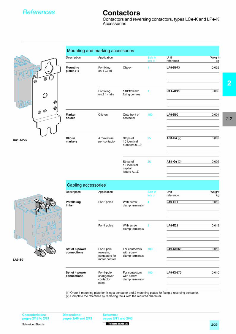
(1) Order 1 mounting plate for fixing a contactor and 2 mounting plates for fixing a reversing contactor.(2) Complete the reference by replacing the
p
with the required character.
Mounting and marking accessories
Description Application
Sold in
Unit Weight
lots of
reference kg
Mounting
For fixing Clip-on
1
LA9-D973
0.025
plates
(1) on 1
4
rail
For fixing 110/120 mm
1
DX1-AP25
0.065on 2
4
rails fixing centres
Marker
Clip-on Onto front of
100
LA9-D90
0.001
holder
contactor
Clip-in
4 maximum Strips of
25
AB1-R
pppp
(2)
0.002
markers
per contactor 10 identicalnumbers 0…9
Strips of
25
AB1-G
pppp
(2)
0.00210 identicalcapitalletters A…Z
Cabling accessories
Description Application
Sold in
Unit Weight
lots of
reference kg
Paralleling
For 2 poles With screw
4
LA9-E01
0.010
links
clamp terminals
For 4 poles With screw
2
LA9-E02
0.015clamp terminals
Set of 6 power
For 3-pole For contactors
100
LA9-K0969
0.010
connections
reversing with screwcontactors for clamp terminalsmotor control
Set of 4 power
For 4-pole For contactors
100
LA9-K0970
0.010
connections
changeover with screwcontactor clamp terminalspairs
Contactors
Contactors and reversing contactors, types LC
p
-K and LP
p
-KAccessories
References
LA9-E01
DX1-AP25
Characteristics:pages 2/18 to 2/21
Dimensions:pages 2/40 and 2/42
Schemes:pages 2/41 and 2/43
22014_Ver4.00-EN.fm Page 39 Thursday, October 25, 2001 5:12 PM

2/40
Schneider Electric
2
2.2
57
58
45
45
35= =
505
557 21
110
45
120
57 27
DZ5-ME5
6
25
22
5722
58
57
LA2-KT
58
38
38 38
27
50 53
45
58
8,65 = = = A1
A2
5735
LA1-K
58 50=
=
35
45
= =
Electronic time delay auxiliary contact blocksLA2-KT
Suppressor modules
ContactorsLC1-K, LC7-K, LP1-K
On panel On mounting rail AM1-DP200 or AM1 DE200 (
7
35 mm)
On one asymmetrical rail DZ5-MB with clip-on mounting plate
LA9-D973 DX1-AP25
On printed circuit board
On contactor
LA4-K
p
On contactor
Contactors
Contactors, types LC
p
-K and LP1-K
Dimensions,mounting
Selection:pages 1/12 to 1/35
Characteristics:pages 2/18 to 2/21
References:pages 2/22 to 2/35
Schemes:page 2/41
22015_Ver3.00-EN.fm Page 40 Thursday, October 25, 2001 5:21 PM

2/41
Schneider Electric
2
2.2
+ –
A1
A2
1815
16
A1
A2
A1
A2
13/N
O14
A1
A2
1/L1
T1/
2
3/L2
T2/
4
5/L3
T3/
6 2221
/NC
A1
A2
1/L1
T1/
2
3/L2
T2/
4
5/L3
T3/
6
A1
A2
1/L1
T1/
2
3/L2
T2/
4
5/L3
T3/
6
7/L4
T4/
8
R1
R2
A1
A2
12
34
R3
R4
53/N
O54
63/N
O64
61/N
C62
51/N
C52
61/N
C62
53/N
O54
54 64 74
53/N
O
63/N
O
73/N
O
83/N
O84
53/N
O54
61/N
C62
73/N
O74
83/N
O84
53/N
O54
61/N
C62
71/N
C72
83/N
O84 54 62 72 82
53/N
O
61/N
C
71/N
C
81/N
C
51/N
C52
61/N
C62
71/N
C72
81/N
C82
31/N
C32
21/N
C22 22 34
21/N
C
33/N
O
33/N
O32
21/N
C22
43/N
O42
53/N
O54
21/N
C22
43/N
O44
53/N
O54
31/N
C32
21/N
C22
53/N
O54
31/N
C32
41/N
C42
21/N
C22
13/N
O14 22
13/N
O14
21/N
C
31/N
C32
43/N
O44
Instantaneous auxiliary contacts LA1-K
Terminal referencing conforming to standard EN 50012For 3-pole contactors
For 4-pole contactors
For contactors LC
p
-K and LP
p
-K
1 C/O
3-pole contactors Integral suppression deviceLC1-K, LC7-K, LP1-K LC7-K
3 P + N/O 3 P + N/C
4-pole contactors, 9 A Integral coil suppression deviceLC1-K, LC7-K, LP1-K LC7-K
4 P 2 P N/O + 2 P N/C
For contactors LC
p
-K and LP
p
-K
2 N/O 2 N/C 1 N/O + 1 N/C
LA1-KN20 LA1-KN02 LA1-KN11LA1-KN207 LA1-KN027 LA1-KN117
4 N/O 3 N/O + 1 N/C 2 N/O + 2 N/C 1 N/O + 3 N/C 4 N/C
LA1-KN40 LA1-KN31 LA1-KN22 LA1-KN13 LA1-KN04LA1-KN407 LA1-KN317 LA1-KN227 LA1-KN137 LA1-KN047
2 N/C 1 N/O + 1 N/C 3 N/O + 1 N/C 2 N/O + 2 N/C 1 N/O + 3 N/C
LA1-KN02M LA1-KN11M LA1-KN31M LA1-KN22M LA1-KN13M
1 N/O + 1 N/C 2 N/O + 2 N/C
LA1-KN11P LA1-KN22P
Electronic time delay auxiliary contact blocks Suppressor modulesLA2-KT LA4-KC LA4-KE
Contactors
Contactors, types LC
p
-K and LP
p
-K
Schemes
Selection:pages 1/12 to 1/35
Characteristics:pages 2/18 to 2/21
References:pages 2/22 to 2/35
Schemes:page 2/41
22015_Ver3.00-EN.fm Page 41 Thursday, October 25, 2001 5:21 PM

2/42
Schneider Electric
2
2.2
57
58
90
90
35= =
505
557 21
57 27
DZ5-ME5
90
110
120
6
25
22
5722
58
5735
LA1-K
58 50=
=
90
80 ==
45
58
8,65 = = =
A1
A2 50
45
8,65===
53
A1
A2
38 38
27
57
LA2-KT
58
38
LC2-K, LC8-K, LP2-K
On one asymmetrical rail DZ5-MB with 2 clip-on mounting plates LA9-D973 or on 2 mounting plates DX1-AP25.
On printed circuit board for reversing contactors or 2 contactors mounted side by side
Electronic time delay contact blocksLA2-KT
Suppressor modules
Reversing contactors
On panel On mounting rail AM1-DP200 or AM1-DE200 (
7
35 mm)
2 x LA9-D973 2 x DX1-AP25
On reversing contactors
LA4-K
p
On reversing contactors
Selection:pages 1/12 to 1/35
Characteristics:pages 2/18 to 2/21
References:pages 2/22 to 2/35
Schemes:page 2/43
Contactors
Reversing contactors, types LC
p
-K and LP2-K
Dimensions,mounting
22018_Ver3.00-EN.fm Page 42 Thursday, October 25, 2001 5:22 PM

2/43
Schneider Electric
2
2.2
+ –
61/N
C62
53/N
O54
13/N
O14
A1
A2
1/L1
T1/
2
3/L2
T2/
4
5/L3
T3/
6
13/N
O14
A1
A2
1/L1
T1/
2
3/L2
T2/
4
5/L3
T3/
6
21/N
C22
A1
A2
1/L1
T1/
2
3/L2
T2/
4
5/L3
T3/
6
21/N
C22
A1
A2
1/L1
T1/
2
3/L2
T2/
4
5/L3
T3/
6
A1
A2
13/N
O14
A1
A2
1/L1
T1/
2
3/L2
T2/
4
5/L3
T3/
6
13/N
O14
A1
A2
1/L1
T1/
2
3/L2
T2/
4
5/L3
T3/
6
21/N
C22
A1
A2
1/L1
T1/
2
3/L2
T2/
4
5/L3
T3/
6
21/N
C22
A1
A2
1/L1
T1/
2
3/L2
T2/
4
5/L3
T3/
6
A1
A2
12
34
56
A1
A2
12
34
56
1/L1
1/L2
1/L3
2/L1
2/L2
2/L3
L1 L2 L3
78
1N
78
2NN
A1
A2
12
34
56
A1
A2
12
34
78
78
56
A1
A2
53/N
O54
63/N
O64
61/N
C62
51/N
C52
54 64 74
53/N
O
63/N
O
73/N
O
83/N
O84 62 74
53/N
O54
61/N
C
73/N
O
83/N
O84
53/N
O54
61/N
C62
71/N
C72
83/N
O84 54 62 72 82
53/N
O
61/N
C
71/N
C
81/N
C
51/N
C52
61/N
C62
71/N
C72
81/N
C82
A1
A2
1815
16
With screw clamp terminals
With Faston connectors or solder pins (printed circuit board)
Instantaneous auxiliary contact blocks LA1-KFor contactors LC
p
-K and LP2-K
For contactors LC
p
-K, LP2-K
Auxiliary contacts with terminal referencing conforming to standard EN 50012 see page
2/41
For contactors LC
p
-K and LP
p
-K
1 C/O
3-pole reversing contactors Integral suppression deviceLC2-K, LC8-K, LP2-K LC8-K
3 P + N/O 3 P + N/C
3 P+ N/O 3 P + N/C
4-pole reversing contactors Integral suppression deviceLC2-K, LC8-K, LP2-K LC8-KWith screw clamp terminals With Faston connectors or
solder pins (printed circuit board)
4 P 4 P
2 N/O 2 N/C 1 N/O + 1 N/C Terminal referencing conforming to standard EN 50012
LA1-KN20 LA1-KN02 LA1-KN11 1 N/O + 1 N/CLA1-KN207 LA1-KN027 LA1-KN117 LA1-KN11P
4 N/O 3 N/O + 1 N/C 2 N/O + 2 N/C 1 N/O + 3 N/C 4 N/C
LA1-KN40 LA1-KN31 LA1-KN22 LA1-KN13 LA1-KN04LA1-KN407 LA1-KN317 LA1-KN227 LA1-KN137 LA1-KN047
Electronic time delay contact blocks Suppressor modulesLA2-KT LA4-KC LA4-KE
Schemes
Selection:pages 1/12 to 1/35
Characteristics:pages 2/18 to 2/21
References:pages 2/22 to 2/35
Dimensions:page 2/42
Contactors
3 and 4-pole reversing contactors, types LC
p
-K and LP
p
-K
22018_Ver3.00-EN.fm Page 43 Thursday, October 25, 2001 5:22 PM


![contactores - telemecanique[1]](https://img.dokumen.tips/doc/110x75/557211ba497959fc0b8f6927/contactores-telemecanique1.jpg)

