Embed Size (px)
Citation preview

Applications & Tools
Answers for industry.
Cover
Technology Template “MotionList Basic”
Technology CPU
Application Description April 2012

2 Technology Template "MotionList Basic"
1.0, Entry ID: 59259273
Cop
yrig
ht
Sie
men
s A
G 2
012
All
right
s re
serv
ed
Siemens Industry Online Support
This entry comes from Siemens Industry Online Support. The following link takes you directly to the download page of this document: http://support.automation.siemens.com/WW/view/en/59259273 Caution: The functions and solutions described in this document are mainly limited to the realization of the automation task. In addition, please note that suitable security measures in compliance with the applicable Industrial Security standards must be taken, if your system is interconnected with other parts of the plant, the company’s network or the Internet. For further information on this issue, please refer to Entry ID 50203404. http://support.automation.siemens.com/WW/view/en/50203404. If you have any questions about this document, please contact us at the following e-mail address: mailto:[email protected]
For further information on this topic, you may also actively use our Siemens Industry Online Support. Add your questions, suggestions and problems and discuss them in our large forum community:

Technology Template "MotionList Basic" 1.0, Entry ID: 59259273 3
Cop
yrig
ht
Sie
men
s A
G 2
012
All
right
s re
serv
ed
s
SIMATIC Technology Template "MotionList Basic" Technology CPU
Technology Template
1
Basics
2
Functional Mechanisms
3
Configuration Process
4
Installation
5
Commissioning
6
Commissioning
7
Operation
8
Program Description
9
Further Notes
10
Bibliographic References
11
History
12

Warranty and Liability
4 Technology Template "MotionList Basic"
1.0, Entry ID: 59259273
Cop
yrig
ht
Sie
men
s A
G 2
012
All
right
s re
serv
ed
Warranty and Liability Note The application examples are not binding and do not claim to be complete
regarding configuration, equipment and any eventuality. The application examples do not represent customer-specific solutions. They are only intended to provide support for typical applications. You are responsible for ensuring that the described products are used correctly. These application examples do not relieve you of your responsibility to use sound practices in application, installation, operation and maintenance. When using these application examples, you recognize that we cannot be made liable for any damage/claims beyond the liability clause described. We reserve the right to make changes to these application examples at any time and without prior notice. If there are any deviations between the recommendations provided in this application example and other Siemens publications – e.g. catalogs – the contents of the other documents have priority.
We accept no liability for information contained in this document. Any claims against us – based on whatever legal reason – resulting from the use of the examples, information, programs, engineering and performance data etc., described in this Application Example shall be excluded. Such an exclusion shall not apply in the case of mandatory liability, e.g. under the German Product Liability Act (“Produkthaftungsgesetz”), in case of intent, gross negligence, or injury of life, body or health, guarantee for the quality of a product, fraudulent concealment of a deficiency or breach of a condition which goes to the root of the contract (“wesentliche Vertragspflichten”). However, claims arising from a breach of a condition which goes to the root of the contract shall be limited to the foreseeable damage which is intrinsic to the contract, unless caused by intent or gross negligence or based on mandatory liability for injury of life, body or health. The above provisions do not imply a change in the burden of proof to your disadvantage. It is not permissible to transfer or copy these application examples or excerpts thereof without express authorization from Siemens Industry Sector.

Table of Contents
Technology Template "MotionList Basic" 1.0, Entry ID: 59259273 5
Cop
yrig
ht
Sie
men
s A
G 2
012
All
right
s re
serv
ed
Table of Contents Warranty and Liability ................................................................................................. 4 1 Technology Template........................................................................................ 8
1.1 Introduction........................................................................................... 8 1.1.1 The technology template...................................................................... 8 1.1.2 Main contents of this technology template........................................... 8 1.1.3 Topics not covered by this application ................................................. 8 1.2 Objective and purpose ......................................................................... 9 1.2.1 Task definition ...................................................................................... 9 1.2.2 Advantages .......................................................................................... 9 1.2.3 Limitations ............................................................................................ 9 1.3 Components of the technology template............................................ 10 1.4 Approved hardware and software ...................................................... 11 1.4.1 Hardware components ....................................................................... 11 1.4.2 Software components......................................................................... 11
2 Basics ............................................................................................................... 15 2.1 Definition of a traverse contour .......................................................... 15 2.1.1 Elements of a traverse contour .......................................................... 15 2.1.2 Conventions for the definition of a motion contour............................. 15 2.1.3 Approach strategies ........................................................................... 16 2.2 Coordinate systems............................................................................ 17 2.2.1 Machine Coordinate System (MCS)................................................... 17 2.2.2 Basic Coordinate System (BCS) ........................................................ 17 2.2.3 Object Coordinate System (OCS) ...................................................... 18 2.3 Motion contour and machine kinematic.............................................. 18 2.3.1 Correlation of the coordinate systems................................................ 18 2.3.2 Available kinematic transformations................................................... 19 2.4 Programming of contour elements ..................................................... 20 2.4.1 Absolute and relative programming ................................................... 21 2.4.2 The “straight line” contour element .................................................... 21 2.4.3 The “circular arc” contour element ..................................................... 22 2.4.4 The “circle” contour element .............................................................. 24
3 Functional Mechanisms.................................................................................. 26 3.1 Saving of the motion contour ............................................................. 26 3.1.1 Required parameters.......................................................................... 26 3.1.2 Structure of the data block ................................................................. 26 3.1.3 Generation of data blocks during the configuration ........................... 27 3.1.4 Generating data blocks in the CPU at runtime................................... 27 3.1.5 Storing the contur elements in the data block.................................... 28 3.2 Processing the motion contour........................................................... 29 3.2.1 Basic function of the technology functions for the interpolation......... 29 3.2.2 Chaining of the technology functions for the interpolation ................. 30 3.2.3 Automated processing of a motion contour ....................................... 30 3.2.4 Instances of the technology functions for the interpolation ................ 31 3.3 Switching conditions of the commands.............................................. 31 3.3.1 Motion commands .............................................................................. 31 3.3.2 System and additional commands ..................................................... 32 3.4 M and H functions .............................................................................. 32 3.4.1 Application of M functions .................................................................. 33 3.4.2 Application of H functions................................................................... 33 3.4.3 Function output of M and H functions ................................................ 33
4 Configuration Process .................................................................................... 34 4.1 Creating the machine axes ................................................................ 34

Table of Contents
6 Technology Template "MotionList Basic"
1.0, Entry ID: 59259273
Cop
yrig
ht
Sie
men
s A
G 2
012
All
right
s re
serv
ed
4.2 Definition of the machine kinematic ................................................... 34 4.2.1 Configuration of the machine kinematic ............................................. 34 4.2.2 Interconnecting the macchine axes.................................................... 35 4.3 Starting point of the technology template........................................... 36
5 Installation........................................................................................................ 38 5.1 Requirements ..................................................................................... 38 5.2 Retrieving the technology template.................................................... 38 5.2.1 STEP 7 archive .................................................................................. 38 5.2.2 Content and structure of the contained STEP 7 projects................... 38 5.3 Integration into your application ......................................................... 39 5.3.1 Transferring the complete S7 program folder .................................... 39 5.3.2 Integrating into your STEP 7 project .................................................. 39 5.3.3 Managing the axes and the path object ............................................. 40 5.3.4 Using the HMI user interface.............................................................. 41
6 Commissioning................................................................................................ 42 6.1 Call environment ................................................................................ 42 6.2 Interfaces............................................................................................ 43 6.2.1 Block interface – FB 540 “MotionList_Basic” ..................................... 43 6.2.2 Expert setting – FB 540 “MotionList_Basic” ....................................... 46 6.2.3 Block interface – FB 541 “HMI_List” .................................................. 47 6.2.4 Block interface – FB 542 “HMI_3D_Movement” ................................ 50 6.2.5 Block interface – FB 543 “HMI_DB_Explorer” ................................... 52 6.2.6 Block interface – FB 544 “Delete_DB” ............................................... 53 6.3 Warning messages and error messages ........................................... 53 6.3.1 Signaling of warning and error events................................................ 53 6.3.2 Warning and error codes – FB 540 “MotionList_Basic” ..................... 54 6.3.3 Warning and error code – FB 541 “HMI_List” .................................... 56 6.3.4 Warning and error codes – FB 542 “HMI_3D_Movement” ................ 57 6.3.5 Warning and error codes – FB 543 “HMI_DB_Explorer” ................... 57 6.3.6 Warning and error codes – FB 544 “Delete_DB” ............................... 58
7 Command Overview ........................................................................................ 59 7.1 Commands available in the technology template .............................. 59 7.2 Motion commands .............................................................................. 60 7.2.1 “SetCartesianTransform”.................................................................... 61 7.2.2 "MoveLinearAbsolute" ........................................................................ 61 7.2.3 “MoveLinearRelative” ......................................................................... 62 7.2.4 “MoveCircAbs_AE”............................................................................. 63 7.2.5 “MoveCircAbs_CE_S” ........................................................................ 63 7.2.6 “MoveCircAbs_CE_L”......................................................................... 64 7.2.7 “MoveCircRel_AE”.............................................................................. 65 7.2.8 “MoveCircRel_CE_S” ......................................................................... 66 7.2.9 “MoveCircRel_CE_L” ......................................................................... 67 7.2.10 “MoveCirclesAbsolute” ....................................................................... 68 7.2.11 “MoveCirclesRelative” ........................................................................ 69 7.3 System commands............................................................................. 70 7.3.1 “ExactStop_ON” ................................................................................. 70 7.3.2 “ExactStop_OFF” ............................................................................... 70 7.3.3 “WaitIN” .............................................................................................. 71 7.3.4 “WaitTime”.......................................................................................... 71 7.3.5 “SetPlane_XY”.................................................................................... 72 7.3.6 “SetPlane_YZ”.................................................................................... 72 7.3.7 “SetPlane_ZX”.................................................................................... 73 7.3.8 “SetTransitionMode”........................................................................... 73 7.3.9 CallContourDB ................................................................................... 74 7.3.10 SetVelocity ......................................................................................... 74

Table of Contents
Technology Template "MotionList Basic" 1.0, Entry ID: 59259273 7
Cop
yrig
ht
Sie
men
s A
G 2
012
All
right
s re
serv
ed
7.3.11 SetAcceleration .................................................................................. 75 7.3.12 SetDeceleration.................................................................................. 76 7.3.13 SetJerk ............................................................................................... 76 7.3.14 SetTolerance ...................................................................................... 77 7.3.15 SetCoordSystem_BCS....................................................................... 77 7.3.16 SetCoordSystem_OCS ...................................................................... 78 7.3.17 JumpToLine........................................................................................ 78 7.4 Additional commands......................................................................... 79 7.4.1 “NOP” ................................................................................................. 79 7.4.2 “EndOfList” ......................................................................................... 79
8 Operation.......................................................................................................... 80 8.1 Control via the block interface............................................................ 80 8.1.1 Motion functions ................................................................................. 81 8.1.2 Management functions....................................................................... 81 8.2 HMI for testing the technology template............................................. 85 8.2.1 The contour editor .............................................................................. 85 8.2.2 Monitoring the traverse motion........................................................... 87 8.2.3 The DB explorer ................................................................................. 88 8.2.4 Axis status display.............................................................................. 89 8.3 Example for programing a contour..................................................... 90 8.3.1 Principle approach.............................................................................. 90 8.3.2 Analysing the contour to be programmed .......................................... 91 8.3.3 Creating the desired contour data block ............................................ 93 8.3.4 Entering the contour elements ........................................................... 93 8.3.5 Starting the processing of the contour entered .................................. 95
9 Program Description ....................................................................................... 97 9.1 Program structure............................................................................... 97 9.1.1 Basic program structure ..................................................................... 97 9.1.2 Steps of the state machine................................................................. 97 9.1.3 Nested call of contour data blocks ..................................................... 99 9.2 Data management............................................................................ 100 9.2.1 Storage location of a motion contour ............................................... 100 9.2.2 Data flow when processing a motion contour .................................. 100 9.2.3 Data flow when manipulating a motion contour ............................... 101
10 Further Notes ................................................................................................. 103 10.1 Position data for the contour definition............................................. 103 10.1.1 Relative and absolute position data ................................................. 103 10.1.2 Cicular constructions ........................................................................ 103 10.2 Dynamic settings .............................................................................. 105 10.2.1 Basics............................................................................................... 105 10.2.2 Axis specific dynamic limits .............................................................. 105 10.2.3 Path-object specific dynamic limits .................................................. 107 10.2.4 Dynamic settings on the technology functions................................. 109 10.2.5 Example for the dynamic setting based on a contour ...................... 109 10.2.6 Points especially worth considering ................................................. 112
11 Bibliographic References ............................................................................. 116 11.1 Bibliographic references................................................................... 116 11.2 Internet Links.................................................................................... 116
12 History............................................................................................................. 119

1 Technology Template
1.1 Introduction
8 Technology Template "MotionList Basic"
1.0, Entry ID: 59259273
Cop
yrig
ht
Sie
men
s A
G 2
012
All
right
s re
serv
ed
1 Technology Template
1.1 Introduction
1.1.1 The technology template
A technology template is a software object or a code block with a defined interface that can be easily integrated into other software projects with little effort and that performs a precisely defined technological task in these projects. The technology template at hand helps you to order the motion control of a path object on straight lines and circular paths in a list and to have these motions executed by the path object. The list compiled for the motion control is saved in a data block. Typical applications for the “MotionList Basic” are the definition and the moving along of simple contours with the help of a path object of the technology CPU, for example, for applying glue on a part or the simple cutting out of sheet metals with the help of a laser or a water jet.
1.1.2 Main contents of this technology template
The following key elements are dealt with in this technology template: • Definition of a motion list for the chained motions of motion functions. • Creating, managing and saving of the motion list in a data block in the
technology CPU. • Processing of the defined motion list with the help of a function block that takes
over the control of the required motion commands in the technology CPU. • Support in the operation of the technology template by integrating a HMI user
interface for the manipulation and management of the motion list and for the monitoring of the defined traverse motion.
1.1.3 Topics not covered by this application
This technology template does not contain a description of … • ...the exact technological processes on which this technology template is
based. • …the application and use of technology functions and technology objects with
the technology CPU. • ...the programming of the technology CPU in STEP 7. Basic knowledge regarding these issues is assumed for the use of this technology template.

1 Technology Template
1.2 Objective and purpose
Technology Template "MotionList Basic" 1.0, Entry ID: 59259273 9
Cop
yrig
ht
Sie
men
s A
G 2
012
All
right
s re
serv
ed
1.2 Objective and purpose
1.2.1 Task definition
A defined contour is to be traversed along straight lines and circular arcs with the technology CPU with the help of a path object.
Figure 1-1 Sample application of the “MotionList Basic"
1.2.2 Advantages
The use of this technology template provides the user with the following advantages: • Easy specification of the desired contour
With the help of the technology templates the desired contour, made up of straight lines and circular arcs, can easily and quickly be stored in a data block. The blocks FB 541 “HMI_List”, FB 543 “HMI_DB_Explorer” and FB 544 “Delete_DB” contained in the technology template provide all functions for the input and management of the contours stored in the data blocks in the technology CPU together with a HMI user interface also contained in the template.
• Easy traversing of the defined contour The contour stored in the data blocks can also be very easily traversed via the technology template. For this purpose the FB 540 “MotionList_Basic” in the technology template is used to interpret the motion commands stored in the data blocks per line and moves along them.
1.2.3 Limitations
The following properties were not considered in the implementation of the technology template. • No monitoring of axis dynamics
A preceding calculation and monitoring of the axis dynamics when moving along the defined contours is not carried out by the technology template. Monitoring is restricted to the monitoring functions of the technology functions used for the chained processing of motion commands in the integrated technology of the technology CPU.

1 Technology Template
1.3 Components of the technology template
10 Technology Template "MotionList Basic"
1.0, Entry ID: 59259273
Cop
yrig
ht
Sie
men
s A
G 2
012
All
right
s re
serv
ed
• No Look Ahead A preliminary assessment of the course of the contour does not take place. In order to process the contour, the next motion command from the motion list is only started during an active motion command.
1.3 Components of the technology template
The technology template is a software package which contains all STEP 7 blocks required for the traverse motion based on a contour stored in a data block.
Figure 1-2 Components contained in the technology template
"MotionList_Basic" technology template
S7-Tech Function block Instance data block
FB 401 "MC_Power"FB 402 "MC_Reset"FB 403 "MC_Home"FB 406 "MC_ReadSysParameter"FB 407 "MC_WriteParameter"FB 480 "MC_SetCartesianTransform"FB 481 "MC_GroupStop"FB 482 "MC_GroupInterrupt"FB 483 "MC_GroupContinue"FB 484 "MC_MoveLinearAbsolute"FB 485 "MC_MoveLinearRelative"FB 486 "MC_MoveCircularAbsolute"FB 487 "MC_MoveCircularRelative"FB 496 "MC_MoveCircles"
FB 540 "MotionList_Basic"
FB541 "HMI_List"FB542 "HMI_3D_Movement"FB543 "HMI_DB_Explorer"
FB544 "Delete_DB"
e.g.. DB 540 "idb_MotionList_1"DB 541 "idb_HMI_List_1"DB 542 "idb_3D_Movement_1"DB 543 "idb_DB_Explorer_1"DB 544 "idb_Delete_DB_1"
e.g.. DB 550 "idb_MotionList_2"DB 551 "idb_HMI_List_2"DB 552 "idb_3D_Movement_2"DB 553 "idb_DB_Explorer_2"DB 554 "idb_Delete_DB_2"
The FB 540 “MotionList_Basic” contains the full functionality to execute the traverse motion based on contour stored in a data block. The FB 541 “HMI_List” contains all management functions in a data block within the technology CPU to create the desired contour. The FB 542 “HMI_3D_Movement” contains all calculations to display the traverse motion in HMI in the XY, YZ, ZX and XZ plane in the coordinate systems OCS, BCS and MCS. The FB 543 “HMI_DB_Explorer” contains all functions to search and display all existing contour data blocks in the CPU. The FB 544 “Delete_DB” contains all functions to delete a contour data block created in the CPU.
Note Due to the complexity of the array accesses and administrative processes to be carried out in the function blocks, all function blocks of the technology template mentioned were realized in SCL (Substation Configuration Language).

1 Technology Template
1.4 Approved hardware and software
Technology Template "MotionList Basic" 1.0, Entry ID: 59259273 11
Cop
yrig
ht
Sie
men
s A
G 2
012
All
right
s re
serv
ed
1.4 Approved hardware and software
1.4.1 Hardware components
Table 1-1 Hardware components
Component Qty. MLFB / order number Note
CPU 315T-2 DP 1 6ES7315-6TH13-0AB0 as of firmware: Version: V2.7.0 / 4.1.5
The CPU executes the user program and the technological functions.
Micro Memory Card 8MB
1 6ES7953-8LP20-0AA0 The S7 program is stored on the MMC.
Table 1-2 Hardware components – Alternative 1
Component Qty. MLFB / order number Note
CPU 317T-2 DP 1 6ES7317-6TK13-0AB0 as of firmware: Version: V2.7.0 / 4.1.5
As an alternative to the CPU 315T-2 DP if the volume is increased.
Micro Memory Card 8MB
1 6ES7953-8LP20-0AA0 The S7 program is stored on the MMC.
Table 1-3 Hardware components – Alternative 2
Component Qty. MLFB / order number Note
CPU 317TF-2 DP 1 6ES7317-6TF14-0AB0 as of firmware: Version: V2.7.1 / 4.1.5
Fail-safe technology CPU for the simultaneous processing of technology and safety program.
Micro Memory Card 8MB
1 6ES7953-8LP20-0AA0 The S7 program is stored on the MMC.
1.4.2 Software components
Standard software components
Table 1-4 Software components
Component Qty. MLFB / order number Note
STEP 7 1 6ES7810-4CC10-0YA5 Version: V5.5 SP2
STEP 7 is the basic package for all optional software packages and used for programming the SIMATIC.
S7-SCL 1 6ES7811-1CC05-0YA5 Version: V5.3 SP6
S7-SCL is a Pascal-like high-level language for STEP 7 for the programming of

1 Technology Template
1.4 Approved hardware and software
12 Technology Template "MotionList Basic"
1.0, Entry ID: 59259273
Cop
yrig
ht
Sie
men
s A
G 2
012
All
right
s re
serv
ed
Component Qty. MLFB / order number Note
programmable logic controllers (PLC).

1 Technology Template
1.4 Approved hardware and software
Technology Template "MotionList Basic" 1.0, Entry ID: 59259273 13
Cop
yrig
ht
Sie
men
s A
G 2
012
All
right
s re
serv
ed
Component Qty. MLFB / order number Note
S7 Technology 1 6ES7864-1CC42-0YA5 Version: V4.2 SP1
Tool for configuring and programming the technology objects of the technology CPU
Software components required for the test program
Table 1-5 Software components
Component Qty. MLFB / order number Note
WinCC flexible Runtime 1 6AV6613-1FA51-3CA0 Version: 2008 SP2 Update 13
The Runtime software is required for operating the HMI user interface.
WinCC flexible 1 6AV6613-0AA51-3CA5 Version: 2008 SP2 Update 13
The engineering software is required, if changes at the HMI user interface shall be performed or the WinCC flexible Runtime shall be newly created.
Sample files and projects
The following list contains all files and archives used in this technology template.
Table 1-6 Files and STEP 7 archives of the technology template
Component Note
59259273_MotionListBasic_CODE_v42.zip This STEP 7 archive contains only the blocks associated with the technology template for integration into a user program.
59259273_CPU315T_MotionListBasic _CODE_E XP_v42.zip 59259273_CPU317T_MotionListBasic _CODE_E XP_v42.zip 59259273_CPU317TF_MotionListBasic _CODE_E XP_v42.zip
This STEP 7 archive contains both the blocks associated with the technology template for the integration into a user program and a test program to check the functions of the HMI user interface.
59259273_MotionListBasic_DOKU_v42_d.pdf This document.

1 Technology Template
1.4 Approved hardware and software
14 Technology Template "MotionList Basic"
1.0, Entry ID: 59259273
Cop
yrig
ht
Sie
men
s A
G 2
012
All
right
s re
serv
ed
Required PLC-Open blocks from the “S7-Tech V4.2” library
The list contains all PLC-Open blocks from the “S7 Tech V4.2” library used for technology function calls in this technology template. The “S7 Tech V4.2” library is included in the “S7-Technology” software.
Table 1-7
PLC-Open blocks Function
FB 407 “MC_WriteParameter” Setting of the most important system variables and configuration data of a technology object.
FB 480 “MC_SetCartesianTransform” Setting up an offset between the basic coordinate system and the object coordinate system by sliding and rotating around the coordinate axis.
FB 481 “MC_GroupStop” Stopping all existing path movements and stopping all participating axes until standstill is reached.
FB 482 “MC_GroupInterrupt” Interruption of a running motion job of a path object. The motion of the path object is interrupted and the path object is stopped. The standstill position is the result from the deceleration ramp, the specified jerk and the underlying kinematic.
FB 483 “MC_GroupContinue” Continuation of the path motion of an axis grouping which was previously interrupted by the “MC_GroupInterrupt” technology function.
FB 484 “MC_MoveLinearAbsolute” Moving a path object along a linear path (straight line) to an absolute target position. The target position is specified three-dimensionally.
FB 485 “MC_MoveLinearRelative” Moving a path object relatively by a specified distance along a linear path (straight line). The distance is specified three-dimensionally.
FB 486 “MC_MoveCircularAbsolute” Moving a path object along a circular path to an absolute target position. The target position is specified three-dimensionally.
FB 487 “MC_MoveCircularRelative” Moving a path object along a circular path to a start point that is relative to the specified target position. The target position is specified three-dimensionally.
FB 496 “MC_MoveCirlces” Moving a path object along a circular path, while specifying a traverse angle, where circular paths > 360°, i.e. with “several revolutions” are possible. Moving along the circular paths can only be carried out in the XY plane, the YZ plane or the ZX plane.

2 Basics
2.1 Definition of a traverse contour
Technology Template "MotionList Basic" 1.0, Entry ID: 59259273 15
Cop
yrig
ht
Sie
men
s A
G 2
012
All
right
s re
serv
ed
2 Basics
2.1 Definition of a traverse contour
The so called traverse contour forms the basis for the defined traversing of the axes of the machine kinematic. Via the traverse contour a path is specified on a part, along which the axes of the machine kinematic are to be moved in order to fulfill the task requested by the machine.
2.1.1 Elements of a traverse contour
In order to define a traverse contour, a simple contour element is usually used, such as, for example, straight line and circular arcs or circles. With these contour elements, even complex motion contours can be described in most cases.
Figure 2-1 Sample contour
Note Specifying the contour can take place in three-dimensional space (3D). However, for a better and easier display of facts, this documentation mainly uses the display on the plane (2D).
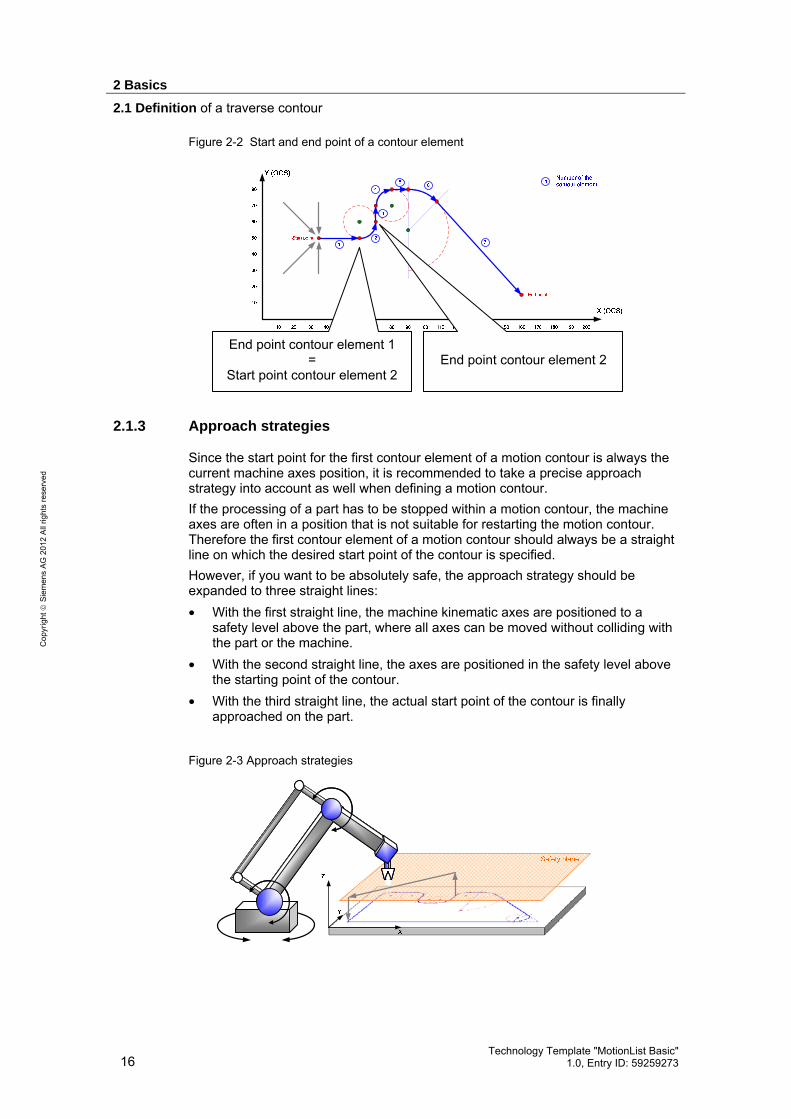
2.1.2 Conventions for the definition of a motion contour
A motion contour is always a continuous path along which the axes of the machine kinematic are to be moved. To start a contour element, the following applies: • The current position of the machine axes is always the start point of the first
contour element of a motion contour. • Each end point of the previous contour element of the motion contour is the
start point for all other contour elements within the motion contour. Due to these conventions for the definition of a motion contour, it is sufficient for the programming of a motion contour to specify only the type of the contour element, e.g. straight line or circular arc and the desired end point of the contour element.
2 Basics
2.1 Definition of a traverse contour
16 Technology Template "MotionList Basic"
1.0, Entry ID: 59259273
Cop
yrig
ht
Sie
men
s A
G 2
012
All
right
s re
serv
ed
Figure 2-2 Start and end point of a contour element
2.1.3 Approach strategies
Since the start point for the first contour element of a motion contour is always the current machine axes position, it is recommended to take a precise approach strategy into account as well when defining a motion contour. If the processing of a part has to be stopped within a motion contour, the machine axes are often in a position that is not suitable for restarting the motion contour. Therefore the first contour element of a motion contour should always be a straight line on which the desired start point of the contour is specified. However, if you want to be absolutely safe, the approach strategy should be expanded to three straight lines: • With the first straight line, the machine kinematic axes are positioned to a
safety level above the part, where all axes can be moved without colliding with the part or the machine.
• With the second straight line, the axes are positioned in the safety level above the starting point of the contour.
• With the third straight line, the actual start point of the contour is finally approached on the part.
Figure 2-3 Approach strategies
End point contour element 1 =
Start point contour element 2
End point contour element 2

2 Basics
2.2 Coordinate systems
Technology Template "MotionList Basic" 1.0, Entry ID: 59259273 17
Cop
yrig
ht
Sie
men
s A
G 2
012
All
right
s re
serv
ed
Therefore it should be possible to safely approach the start point of the contour from any position of the machine kinematic axes without compromising the machine or the part.
2.2 Coordinate systems
Three different coordinate systems have been implemented for the interpolation in the technology CPU: • The machine-coordinate system (MCS) or the axis coordinate system • The basic coordinate system (BCS) • The object coordinate system (OCS)
Figure 2-4 The coordinate systems of the technology CPU
2.2.1 Machine Coordinate System (MCS)
In the machine coordinate system or axis coordinate system (MCS) the individual axes of the machine are included. The axes of the machine coordinate system (MCS) do not have to form a Cartesian coordinate system, i.e. they do not have to be arranged at an angle of 90° to each other but can be suitably distributed in space according to the desired kinematic.
2.2.2 Basic Coordinate System (BCS)
The basic coordinate system (BCS) provides the basic coordinate system for programming a motion contour. The basic coordinate system is a right-handed Cartesian coordinate system, i.e. the axes are each arranged at an angle of 90°. The name and orientation of the axes can be allocated with the help of the fingers of the right hand (right-hand rule): • Thumb: is pointing in the direction of the X axis • Index finger: is pointing in the direction of the Y axis • Middle finger: is pointing in the direction of the Z axis

2 Basics
2.3 Motion contour and machine kinematic
18 Technology Template "MotionList Basic"
1.0, Entry ID: 59259273
Cop
yrig
ht
Sie
men
s A
G 2
012
All
right
s re
serv
ed
Figure 2-5 Right-hand rule
2.2.3 Object Coordinate System (OCS)
The object coordinate system (OCS) is also a right-hand Cartesian coordinate system which can be formed by sliding and rotating the basic coordinate system. A part that is not located parallel to the basic coordinate system (BCS) can be quickly and easily processed via the object coordinate system (OCS). For this purpose, the basic coordinate system (BCS) has to be moved and rotated in a way so that the resulting object coordinate system lies parallel to the plane of the part that is to be processed.
Figure 2-6 The object coordinate system (OCS)
2.3 Motion contour and machine kinematic
2.3.1 Correlation of the coordinate systems
The correlation between the motion contour and machine kinematic is achieved via the kinematic transformation of the technology CPU. The axes for controlling the machine kinematic are included in the machine coordi-nate system (MCS). Programming the motion contour in order to move the machine axes is performed in the basic coordinate system (BCS) or the object coordinate system (OCS). Therefore the position of the machine axes in the machine coordinate system (MCS) has to be established on the basis of the

2 Basics
2.3 Motion contour and machine kinematic
Technology Template "MotionList Basic" 1.0, Entry ID: 59259273 19
Cop
yrig
ht
Sie
men
s A
G 2
012
All
right
s re
serv
ed
programmed position in the basic coordinate system (BCS) or the object coordinate system (OCS) via the kinematic transformation in the technology CPU.
Figure 2-7 Correlation of the coordinate systems
Note The correlation between the machine coordinate system (MCS) and the basic coordinate system (BCS) is specified in S7T Config via the selection of the kinematic transformation.
In contrast, the formation of the object coordinate system (OCS) from of the basic coordinate system (BCS) can be performed during runtime via the FB 480 “MC_SetCartesianTransform” technology function.
2.3.2 Available kinematic transformations
The following kinematics, implemented in the technology CPU, can be selected for the kinematic transformation between basic coordinate system (BCS) and machine coordinate system (MCS) during the configuration phase in S7T Config:
Table 2-1
Figure Dimension Description
2D / 3D Cartesian gantry Linear axis movements through linear axes in the plane (2D) and in space (3D).
2D Roll picker (cross slide) Linear axis movements through two fixed drive axes in the plane (2D) with the help of a rotating belt. The rotary direction of the drive axes determines the direction of the linear movement in the plane.

2 Basics
2.4 Programming of contour elements
20 Technology Template "MotionList Basic"
1.0, Entry ID: 59259273
Cop
yrig
ht
Sie
men
s A
G 2
012
All
right
s re
serv
ed
Figure Dimension Description
3D Scara Axis movements in space (3D) around a central pivot point. The arm of the Scara kinematic can be equipped with two pivot points to increase the working area of the kinematic.
2D Delta 2 picker Axis movements in the plane (2D) with high dynamic realized with the help of two rotary axes and mechanical coupler elements. The tool carrier (e.g. gripper) always remains in the same orientation with the work level when moving the Delta 2 picker.
3D Delta 3 picker Axis movements in space (3D) with high dynamic realized with the help of three rotary axes and mechanical coupler elements. The tool carrier (e.g. gripper) always remains in the same orientation with the work level when moving the Delta 3 picker.
3D Articulated arm (top loader) Axis movements in space (3D) through the pivotal axis in the base point of the kinematic and the two rotary axes of the articulated arms.
Note 2D kinematics support only one interpolatory movement in one plane (2D) and cannot be expanded to an interpolatory movement in space (3D).
The calculation of the machine axes positions to be approached when a position in the basic coordinate system (BCS) is specified via the X, Y and Z coordinate is performed automatically via the kinematic transformation in the firmware of the technology CPU in dependence of the selected kinematic.
2.4 Programming of contour elements
Programming of a motion contour is performed by stringing together various contour elements. The contour elements are defined by selecting the element type and the configuration of the end position or additional position or parameter values.

2 Basics
2.4 Programming of contour elements
Technology Template "MotionList Basic" 1.0, Entry ID: 59259273 21
Cop
yrig
ht
Sie
men
s A
G 2
012
All
right
s re
serv
ed
The definition of the end positions of the contour elements is performed on the basic coordinate system (BCS) or in the object coordinate system (OCS), in other words in a right-handed Cartesian coordinate system.
Figure 2-8 Sample contour
2.4.1 Absolute and relative programming
The programming of the end position of a contour element can be performed in two different ways: • Absolute programming:
The absolute position in the basic coordinate system (BCS) or the object coordinate system is programmed as the end position of the contour element, i.e. the precise coordinates are specified in X, Y and Z direction in the respective coordinate system.
• Relative programming: The relative position in the basic coordinate system (BCS) or object coordinate system is programmed as the end position of the contour element, i.e. the distance of the end position to the start point of the contour element is specified in X, Y and Z direction in the respective coordinate system.
Both programming types are equally significant. However, different commands are available for absolute and relative programming. In certain situations either one or the other programming type may offer advantages. The relative programming for example can be easily applied with X=10, if a distance of 10mm is to be bridged with the help of a straight line, in the direction of the X axis of the coordinate system.
2.4.2 The “straight line” contour element
Via the “straight line” contour element type, a linear movement between two points can be realized. The straight line can be positioned as desired in space (3D).
Absolute programming
For the absolute programming of a straight line, the end point of the straight line is specified as absolute position in the coordinate system (BCS or OCS).

2 Basics
2.4 Programming of contour elements
22 Technology Template "MotionList Basic"
1.0, Entry ID: 59259273
Cop
yrig
ht
Sie
men
s A
G 2
012
All
right
s re
serv
ed
Figure 2-9 Straight line – absolute programming
Relative programming
For the relative programming of a straight line, the distance of the end point of the straight line is specified in relation to the start point of the straight line in the coordinate system (BCS or OCS).
Figure 2-10 Straight line – relative programming
2.4.3 The “circular arc” contour element
Via the “circular arc” contour element type, a circular movement between two points can be realized. The circular arc can be positioned as desired in space (3D). However, the full definition of a circular arc requires the specification of an intermediate point on the desired circular arc or the specification of the circular center point in addition to the programming of the circular end point together with the selection of the desired arc segment. For the traverse motion of the “circular arc” contour element, a straight line between start point, center point and end point or start point, intermediate point and end point of the circle is spanned, in which the circular arc is realized.
Absolute programming
For the absolute programming of a circular arc, the end point and the center point or an intermediate point is specified on the circular arc as absolute position in the coordinate system (BCS or OCS).

2 Basics
2.4 Programming of contour elements
Technology Template "MotionList Basic" 1.0, Entry ID: 59259273 23
Cop
yrig
ht
Sie
men
s A
G 2
012
All
right
s re
serv
ed
Figure 2-11 Circular arc – absolute programming
Relative programming
For the relative programming of a circular arc, the distance of the end point in relation to start point of the circle, and the distance of the center point or the intermediate point to the distance of the respective point in relation to the start point of the circle in the coordinate system (BCS or OCS) is specified.
Figure 2-12 Circular arc – relative programming
Selection of the circular arc section
If a circular arc is defined via end point and center point, the desired circular arc section always has to be selected as well. If start point, center point and end point of the circular arc are not located on one line (semi circle), it can generally be distinguished between the two following circular arc sections: • Short arc segment (aperture angle < 180°) • Long arc segment (aperture angle > 180°)
Figure 2-13 Selection of the circular arc
Short arc segment
Long arc segment

2 Basics
2.4 Programming of contour elements
24 Technology Template "MotionList Basic"
1.0, Entry ID: 59259273
Cop
yrig
ht
Sie
men
s A
G 2
012
All
right
s re
serv
ed
2.4.4 The “circle” contour element
Via the “circle” contour element type, circular movements with “several revolutions” can be realized. The location of the circle is defined via the center point of the circle. The traverse motion on the circular arc is performed via the definition of an angle that can also be specified larger than 360°. The sign of the angle value specifies the direction of motion along the circular arc. The limitation of this contour element type is that circles can only be defined in one coordinate system plane (X-Y plane, Y-Z plane or Z-X plane) each and that they cannot be located in space (3D) as desired.
Note However, in order to be able to place the circular motions as desired in space (3D), the FB 480 “MC_SetCartesianTransform” technology function for moving and rotating the object coordinate system (OCS) can be used. In that case, the circular motion also has to be carried out in OCS.
Absolute programming
For the absolute programming of a circle, the center point is specified as absolute position in the coordinate system (BCS or OCS). The angle for the movement along the circular arc is always specified as programmed absolute.
Figure 2-14 Circle – absolute programming
Relative programming
For the relative programming of a circle, the distance of the center point in relation to the start point of the circle is specified in the coordinate system (BCS or OCS). The angle for the movement along the circular arc is always specified as programmed absolute.
2 Basics
2.4 Programming of contour elements
Technology Template "MotionList Basic" 1.0, Entry ID: 59259273 25
Cop
yrig
ht
Sie
men
s A
G 2
012
All
right
s re
serv
ed
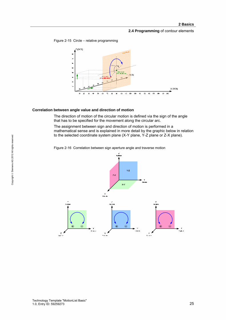
Figure 2-15 Circle – relative programming
Correlation between angle value and direction of motion
The direction of motion of the circular motion is defined via the sign of the angle that has to be specified for the movement along the circular arc. The assignment between sign and direction of motion is performed in a mathematical sense and is explained in more detail by the graphic below in relation to the selected coordinate system plane (X-Y plane, Y-Z plane or Z-X plane).
Figure 2-16 Correlation between sign aperture angle and traverse motion

3 Functional Mechanisms
3.1 Saving of the motion contour
26 Technology Template "MotionList Basic"
1.0, Entry ID: 59259273
Cop
yrig
ht
Sie
men
s A
G 2
012
All
right
s re
serv
ed
3 Functional Mechanisms
3.1 Saving of the motion contour
In order to be able to carry out a desired interpolated traverse motion with the technology CPU, the motion contour has to be saved in the CPU. For this purpose, all required parameters have to be saved in a data block in the CPU.
3.1.1 Required parameters
If all parameters of the technology functions are analyzed that are available for an interpolated motion in the technology CPU, the result will be the parameters that need to be supplied with values when the respective technology function is called in the technology template.
Figure 3-1 Analysis of the parameters of the technology functions for the interpolation
Axi
s
Axes
Gro
up
Trac
king
Axi
s
Exec
ute
Pos
ition
Segm
ent
AuxP
oint
EndP
oint
Cen
terP
oint
Dis
tanc
e
Vel
ocity
Acc
eler
atio
n
Dec
eler
atio
n
Jerk
Arc
Coo
rdSy
stem
Mod
e
Buffe
rMod
e
Tran
sitio
nMod
e
Circ
Mod
e
Poly
nom
ialM
ode
Poly
nom
Dat
a
Dire
ctio
n
Pat
hCho
ice
Tran
sitio
nPar
amet
er
Dyn
amic
Ada
ptio
n
Torq
ue
Tole
ranc
e
Cur
rent
Posi
tionC
ontro
l
Tran
sX
Tran
sY
Tran
sZ
Rot
X
Rot
Y
Rot
Z
Abs
olut
e
Path
Plan
e
INT
INT
INT
BOO
L
RE
AL
INT
XYZV
ecto
r
XYZV
ecto
r
XYZV
ecto
r
RE
AL
RE
AL
RE
AL
RE
AL
RE
AL
RE
AL
INT
INT
INT
INT
INT
INT
AN
Y
INT
INT
RE
AL
INT
RE
AL
INT
BOO
L
BOO
L
RE
AL
RE
AL
RE
AL
RE
AL
RE
AL
RE
AL
BOO
L
INT
480 MC_SetCartesianTransform Path objects x x x x x x x x x484 MC_MoveLinearAbsolute Path objects x x x x x x x x x x x x485 MC_MoveLinearRelative Path objects x x x x x x x x x x x x486 MC_MoveCircularAbsolute Path objects x x x x x x x x x x x x x x487 MC_MoveCircularRelative Path objects x x x x x x x x x x x x x x496 MC_MoveCircles Path objects x x x x x x x x x x x x x x
Technology functionsof an interpolated movementusing the Technology CPU
The parameters of the technology functions are divided in the following areas: • Inputs and parameters that are internally managed by the technology template,
such as, e.g. the “execute” input of the technology functions. • Parameters that cannot generally be changed during the execution of the
traverse motion, such as, e.g. the traverse speed. • Parameters that have to be specified in dependence of the respective contour
element and therefore in dependence of the respective interpolated motion, such as, e.g. the end position of the contour element or the interpolated motion.
Therefore, the parameters required for the definition of a motion contour arise regarding: • Selection of the desired contour element or of the technology function for the
interpolated motion. • Definition of the end point of the contour element. • Definition of the center point or of the intermediate point of the contour element
for circular motions.
3.1.2 Structure of the data block
From the parameters required for the definition of a motion contour, the structure of a data block can now be generated as UDT:

3 Functional Mechanisms
3.1 Saving of the motion contour
Technology Template "MotionList Basic" 1.0, Entry ID: 59259273 27
Cop
yrig
ht
Sie
men
s A
G 2
012
All
right
s re
serv
ed
• UDT 541 “ContourListData” Data record of a contour element, consisting of contour element type, end point, additional point and contour element-specific additional values (M and H function)
• UDT 540 “ContourList” Combining the individual data records of the contour elements in an array with 100 entries.
Figure 3-2 Structure of the individual “ContourListData” data record of the contour
Figure 3-3 Structure of the “ContourList” data block as array of the data records
3.1.3 Generation of data blocks during the configuration
If a data block is to be created in STEP 7 to save a motion contour already during the configuration phase, the UDT 540 “ContourList” data type is to be used.
Note By using the UDT 540 “ContourList”, the content of the data blocks for saving a motion contour can very easily be read in the online view of STEP 7.
3.1.4 Generating data blocks in the CPU at runtime
Data blocks can also be generated to save a motion contour during the runtime of the STEP 7 program in the CPU in the main memory of the CPU with the help of the SFC 22 “CREAT_DB” system function. A data block for 100 data records is created via the SFC 22 “CREAT_DB” each with 32 bytes of data, meaning a data block with a length of 3200 bytes. Although the generation of the data block is only performed in the main memory of the CPU, the entire main memory, however, is retentively designed, so that data blocks and also their content remain present when the CPU is switched on and off.

3 Functional Mechanisms
3.1 Saving of the motion contour
28 Technology Template "MotionList Basic"
1.0, Entry ID: 59259273
Cop
yrig
ht
Sie
men
s A
G 2
012
All
right
s re
serv
ed
ATTENTION If a full reset is performed on the CPU, the data blocks created at runtime will be deleted again, since they are not saved on the MMC of the CPU.
If the data blocks created at runtime are to be saved permanently in the CPU, they have to be transferred with the help of the SIMATIC Manager from the CPU to the PG (PLC > Upload Station to PG…) and afterwards, if required, the desired data blocks have to be loaded to the CPU again. As a result, the data blocks are permanently stored on the MMC of the CPU together with the contour contained therein.
Note Since the data block for saving a motion contour is created via the SFC 22 “CREAT_DB” as a data area with 3200 data entries of the “byte” type, the content of the data block is only readable with difficulty in the online view of STEP 7.
3.1.5 Storing the contour elements in the data block
The storage of the required data of a contour element is performed “line by line” in the individual array elements of the data block according to the structure defined by UDT 541 “ContourListData”.
Figure 3-4 Structure of the individual “ContourListData” data record of the contour
Table 3-1 Elements data record of the „ContourListData“
Entry Significance Notes
ContourCommand Definition of the contour element type as integer number.
EndPoint Definition of the end point of the contour element by specifying individual coordinates for X, Y and Z direction.
For certain commands or contour elements, the individual coordinates can also have a different significance, e.g. for circles the EndPoint.X is interpreted as angle value.
3 Functional Mechanisms
3.2 Processing the motion contour
Technology Template "MotionList Basic" 1.0, Entry ID: 59259273 29
Cop
yrig
ht
Sie
men
s A
G 2
012
All
right
s re
serv
ed
Entry Significance Notes
AuxPoint Definition of the center point or an intermediate point for circular motions by specifying individual coordinates for X, Y and Z direction.
H_Function Definition of a REAL number to be output during the processing of the contour element.
M_Function Definition of an INTEGER number to be output during the processing of the contour element.
These auxiliary values can be used for the control of the machine during the processing of a contour, e.g. to switch a laser on and off or to control the laser performance.
3.2 Processing the motion contour
Knowledge of the status signals of the technology functions is of decisive significance for the automatic processing of the technology functions for the interpolation in the technology CPU.
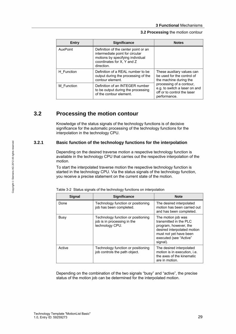
3.2.1 Basic function of the technology functions for the interpolation
Depending on the desired traverse motion a respective technology function is available in the technology CPU that carries out the respective interpolation of the motion. To start the interpolated traverse motion the respective technology function is started in the technology CPU. Via the status signals of the technology function, you receive a precise statement on the current state of the motion.
Table 3-2 Status signals of the technology functions on interpolation
Signal Significance Note
Done Technology function or positioning job has been completed.
The desired interpolated motion has been carried out and has been completed.
Busy Technology function or positioning job is in processing in the technology CPU.
The motion job was transmitted in the PLC program, however, the desired interpolated motion must not yet have been executed (see “Active” signal).
Active Technology function or positioning job controls the path object.
The desired interpolated motion is in execution, i.e. the axes of the kinematic are in motion.
Depending on the combination of the two signals “busy” and “active”, the precise status of the motion job can be determined for the interpolated motion.

3 Functional Mechanisms
3.2 Processing the motion contour
30 Technology Template "MotionList Basic"
1.0, Entry ID: 59259273
Cop
yrig
ht
Sie
men
s A
G 2
012
All
right
s re
serv
ed
3.2.2 Chaining of the technology functions for the interpolation
In order to move along an entire contour, made up of planes and circular arcs, several interpolated traverse motions have to be carried out successively. The individual traverse motions have to be carried out without interruption, i.e. they have to be blended. To achieve this, the technology functions have to be chained in the technology CPU. The order buffer of the technology CPU always includes two motion commands for an interpolated motion. The chaining of the technology functions has to be carried out according to the following scheme: 1. The technology function for the first interpolated motion is started from the
technology CPU. The command is transmitted and instantly executed in the technology which is displayed by the status signals “Busy”=True and “Active”=True.
2. Whilst the first command is running, the technology function for the next interpolated motion has to be started so that it can be attached in a blended way at the end of the first motion, i.e. attached without a drop of the path speed. The status signals of this technology function shows that the job has been transmitted with “Busy”=True and “Active”=False but that the axes of the kinematic are not yet controlled by this technology function.
3. As soon as the first technology function reports via the status signal “Done”=True that the first interpolated motion has been completed and the second technology function reports via “Busy“=True and “Active”= True that it has taken on the motion control, the next technology function can be written in the order buffer.
4. This process is continued until no new technology function is written in the order buffer and the interpolated motion is therefore completed with the processing of the last technology function.
Figure 3-5 Blending of two motion commands (technology functions)
3.2.3 Automated processing of a motion contour
For the automated processing of a motion contour defined in a data block the above mentioned principle now has to be applied as follows:

3 Functional Mechanisms
3.3 Switching conditions of the commands
Technology Template "MotionList Basic" 1.0, Entry ID: 59259273 31
Cop
yrig
ht
Sie
men
s A
G 2
012
All
right
s re
serv
ed
1. The first motion set or the first contour element is read out of the data block and the resulting technology function is determined.
2. The technology function is transmitted, this starts the motion instantly. 3. The next contour element is read out of the data block and the respective
technology function is specified. 4. This technology function is transmitted. However, this motion is to be blended
with the currently active interpolated motion, this is why the execution of this function should be waited for until the motion has reached the “blending point” for starting the subsequent motion.
5. Once the first technology function has been completed, the next contour element can be read out of the data block and the respective technology function can be determined and started.
6. This process is repeated until the contour stored in the data block has been fully processed.
Note The length of the individual interpolated motions has to be selected in a way so that the technology CPU can start the technology function of the subsequent motion and transfer it to the technology within the cycle time. Otherwise the traverse motion may be interrupted at the end point of the previous interpolated motion.
3.2.4 Instances of the technology functions for the interpolation
In order to be able to execute the desired traverse motion along the defined motion contour, there always have to be two instances of the technology functions for the interpolation available at the same time. An instance for the execution of the currently active motion and an instance of the technology function that is transferred to the order buffer for the subsequent motion. Since the currently active motion and the subsequent motion can be of the same type, e.g. execution of two linear motions successively, there have to be two instances available in the technology template of each technology function used. For the automatic processing of a motion contour whose motion has just been completed, the instance for the next entry in the order buffer is then used each time.
3.3 Switching conditions of the commands
The switching conditions are of decisive significance for the processing of a motion contour that has been saved line by line in a data block. Via the switching condition it is determined when the next command included in the traverse motion is used for the execution in the technology template.
3.3.1 Motion commands
For each motion command within a motion contour an individual instance has to be used in the technology template. Additionally, the provision of the technology functions for the interpolated motions in the order buffer has to be as quick as possible, so that there is no danger to create a stop of the traverse motion. For this reason the switching conditions for motion commands are:

3 Functional Mechanisms
3.4 M and H functions
32 Technology Template "MotionList Basic"
1.0, Entry ID: 59259273
Cop
yrig
ht
Sie
men
s A
G 2
012
All
right
s re
serv
ed
• The fastest possible provision of the interpolated motion of required technology functions in the technology of the technology CPU. This is respectively valid for the currently executed and the subsequent motion.
• The reading in and processing of the next line of the motion contour saved in the data block as soon as the currently active motion was completed.
Note The length of the individual interpolated motions has to be selected in a way so that the technology CPU can provide the technology function of the subsequent motion in the order buffer within the cycle time.
Otherwise the traverse motion may be interrupted at the end point of the previous interpolated motion.
3.3.2 System and additional commands
For the system and additional commands other switching conditions apply, since they are often not linked with an interpolated motion and therefore not with a technology function. Via system and additional commands, parameters are set or administrative information is transferred to the technology template. For this reason, the switching conditions for system and additional commands are: • Commands for the setting of parameters or for the transfer of administrative
information to the technology template can be performed instantly, even during the execution of a motion command. These commands do not cause an instance change within the technology template for the function to be executed. They can therefore be executed straight after one another and do not have to wait for the end of the currently active traverse motion.
• Commands that cause a response depending on the traverse motion or that wait for a response on the block of the technology template, such as, for example, waiting times, can only be executed at the end of a currently active motion. They are only started once the currently active motion command delivers the “Done” status signal. The start of the next command from the motion contour is also only executed at the end of this command.
3.4 M and H functions
During the processing of a motion contour it is often also necessary to output signals that affect the process. This is the purpose of the M and H functions that can be attached to each individual motion block.

3 Functional Mechanisms
3.4 M and H functions
Technology Template "MotionList Basic" 1.0, Entry ID: 59259273 33
Cop
yrig
ht
Sie
men
s A
G 2
012
All
right
s re
serv
ed
3.4.1 Application of M functions
Via the M function an integer value can be output parallel to the execution of the current motion command, which is for example, used for the control of aggregates of the machine (open/close gripper, cooling water on/off).
3.4.2 Application of H functions
Via the H function a real value can be output parallel to the execution of the current motion command, which can, for example, be used for the configuration of aggregates of the machine (control of cooling water pressure, regulation of the amount of glue application, adjustment of the laser performance to processing …).
3.4.3 Function output of M and H functions
The output of function values of the M and H functions each take place with the start of the processing of the motion command, in whose correlation the respective function is programmed in the motion contour. Different values can be specified for the M and the H function in the data block of the motion contour that are output simultaneously. The duration of the output of the M and H function takes place during the processing of the respective motion command, this means only at the beginning of the next motion, system or additional command.

4 Configuration Process
4.1 Creating the machine axes
34 Technology Template "MotionList Basic"
1.0, Entry ID: 59259273
Cop
yrig
ht
Sie
men
s A
G 2
012
All
right
s re
serv
ed
4 Configuration Process
4.1 Creating the machine axes
Create the axes of your machine as usual in S7T Config. Make sure to select the “Path interpolation” axis technology so that the created axes can be used as path axes in connection with a path object.
Figure 4-1 Creating the machine axes
Note When selecting the “path interpolation” axis technology, the axis technologies “speed control” and “positioning” are automatically selected.
4.2 Definition of the machine kinematic
Controlling the machine axes by the technology template is performed with the help of a path object. The technology template transfers the desired axis position in the basic coordinate system (BCS) or object coordinate system (OCS) to the path object, which takes on the control of the machine axes via the kinematic transformation included in the path object. As a result, the present technology template can be used for any kinematic included in S7 technology.
4.2.1 Configuration of the machine kinematic
The selection and configuration of the machine kinematic is performed by creating the path object in S7T Config.

4 Configuration Process
4.2 Definition of the machine kinematic
Technology Template "MotionList Basic" 1.0, Entry ID: 59259273 35
Cop
yrig
ht
Sie
men
s A
G 2
012
All
right
s re
serv
ed
In the “Configuration – Configuration” section, the desired kinematic is selected and as a result the kinematic transformation of the path object is specified. Via the kinematic type the processing space is furthermore specified, e.g. two dimensional in the plane (2D) or three dimensional in space (3D).
Figure 4-2 Selection of the machine kinematic (e.g. Cartesian gantry)
In the “Configuration – Offset” section, the settings for moving the kinematic zero point in relation to the origin of the basic coordinate system (BCS) via offset values is performed. Thus, the selected kinematic position is placed in relation to the basic coordinate system (BCS) so that the specified positions can be consistently carried out for the machine in this coordinate system.
Figure 4-3 Moving the kinematic zero point (e.g. Cartesian gantry)
4.2.2 Interconnecting the machine axes
Once the present machine kinematic has been selected, the kinematic axes now have to be assigned to the real machine axes.

4 Configuration Process
4.3 Starting point of the technology template
36 Technology Template "MotionList Basic"
1.0, Entry ID: 59259273
Cop
yrig
ht
Sie
men
s A
G 2
012
All
right
s re
serv
ed
In the “interconnections” sections this assignment can be carried out with the already created technology objects of the machine axes.
Figure 4-4 Interconnections of the machine axes on the path object
- The assignment of the “Position axis for path-synchronous motion” is of no significance for the use of this technology template. If necessary, the setting for the definition of the manual axis for the gripper alignment may be required when the "Scara” kinematic is used. Further information on this subject can be found in the manual for the S7 technology. The same is the case for the assignment in the "Follow the motion of" section. This setting is usually not required for the use of this technology template since the execution of the motion contour is normally not on a moving object. However, if this should be the case, of course the function can be used, as explained in the manual to the S7 technology.
Note Note the consistent linking of the machine axes with the axis direction of the basic coordinate system of the path object (right-handed coordinate system) when interconnecting machine axes in the path object.
4.3 Starting point of the technology template
The present technology template can generally be used with any path object and therefore with any kinematic available in the technology CPU. The programming of the motion contour is in the basic coordinate system (BCS) or in the object coordinate system (OCS) and transfers motion jobs via the path-object specific technology functions in the technology CPU to the path object.

4 Configuration Process
4.3 Starting point of the technology template
Technology Template "MotionList Basic" 1.0, Entry ID: 59259273 37
Cop
yrig
ht
Sie
men
s A
G 2
012
All
right
s re
serv
ed
Controlling the actual machine axes is then performed through the path object with the help of the included kinematic transformation.
Figure 4-5 Principle function of a path object
5 Installation
5.1 Requirements
38 Technology Template "MotionList Basic"
1.0, Entry ID: 59259273
Cop
yrig
ht
Sie
men
s A
G 2
012
All
right
s re
serv
ed
5 Installation
5.1 Requirements
To be able to integrate the technology template into your STEP 7 project, the required technology objects, such as axes and a path object with the respective definition of the machine kinematic, have to have been created in the technology CPU via S7T. Creating the required technology objects corresponds with the general approach for axes and path objects for the use of the interpolation in the technology CPU. This is why this is not the subject of this documentation. More precise notes on this subject can be found in the manual for the S7 technology.
5.2 Retrieving the technology template
The technology template is delivered as STEP 7 archive. This archive has to be extracted via STEP 7 before the technology template can be used.
5.2.1 STEP 7 archive
Two different archives are available for the technology template: • A STEP 7 archive, which only contains all the blocks required for the
technology template. • A STEP 7 archive, which in addition to the blocks required for the technology
template also contains a test program for the template including an HMI user interface.
5.2.2 Content and structure of the contained STEP 7 projects
The STEP 7 project contained in the archives may include several S7 program folders in which all the elements required for the use of the technology template are stored: • MotionList_Basic
Program folder that contains all blocks required for the technology template including the technology functions used in the technology template and the system and standard functions.
• MotionDB_Examples Program folder that includes some examples for data blocks of motion contours that can be used as sample contours in the test program for the technology template.

5 Installation
5.3 Integration into your application
Technology Template "MotionList Basic" 1.0, Entry ID: 59259273 39
Cop
yrig
ht
Sie
men
s A
G 2
012
All
right
s re
serv
ed
Figure 5-1 Content and structure of the STEP 7 project (incl. test program)
Apart from the mentioned program folders, the STEP 7 archive with test program also contains a SIMATIC station with technology CPU, which contains the test program including all necessary blocks for the demonstration of the technology template and a WinCC flexible project which contains the HMI user interface for the operation of the technology template.
5.3 Integration into your application
For easy and quick transfer of the technology template to your STEP 7 project, you should proceed as described below.
5.3.1 Transferring the complete S7 program folder
Copy the complete S7 program folder from the STEP 7 archive of the technology template to the root directory of your STEP 7 project. Now all blocks required for the technology template are instantly available in your user program.
5.3.2 Integrating into your STEP 7 project
To integrate the elements of the technology template, you now only have to copy the individual blocks of the template from the copied S7 program folder to the block folder of your application. Afterwards you can use the technology template by simply calling the blocks, such as, e.g. the FB 540 “MotionList_Basic” for the processing of a motion contour saved in a data block.
SIMATIC station for the test program of the technology template
WinCC flexible project of the HMI user interface of the test program for the technology template
S7 program folder of individual function blocks of the technology template
Example for contour data blocks for the use of motion contours in the test program.

5 Installation
5.3 Integration into your application
40 Technology Template "MotionList Basic"
1.0, Entry ID: 59259273
Cop
yrig
ht
Sie
men
s A
G 2
012
All
right
s re
serv
ed
Table 5-1 Call of the function block of the technology template
STL FBD
FB 540 “MotionList_
Basic”
The call has to be performed in a cyclically starting OB or FB block. Processing control by a timer interrupt (e.g. in OB 35) is not required, but possible.
5.3.3 Managing the axes and the path object
The FB 540 “MotionList_Basic” block only assumes the control of the path object for the execution of the interpolated motion stored in the motion contour. However, managing the axes and the path object (enable, acknowledgement of errors) must be in the user program in which the block is called.
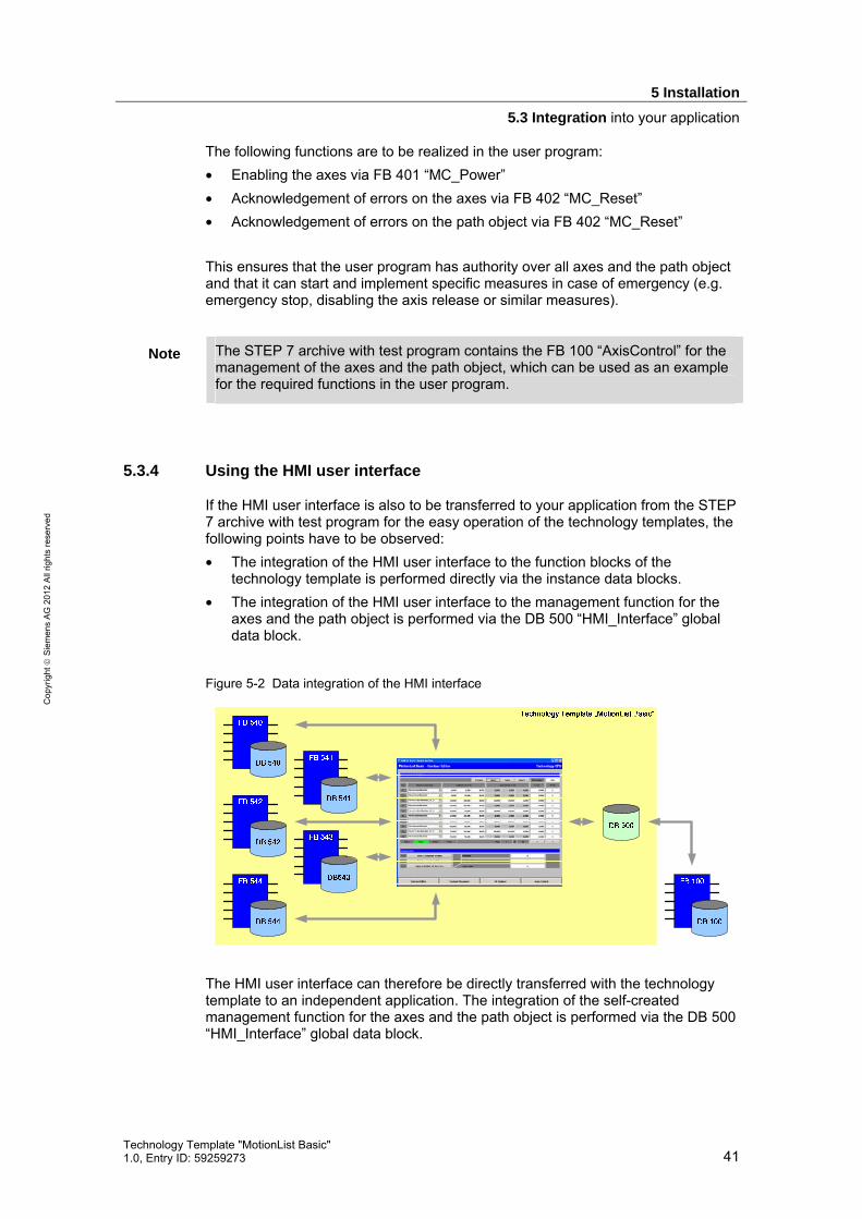
5 Installation
5.3 Integration into your application
Technology Template "MotionList Basic" 1.0, Entry ID: 59259273 41
Cop
yrig
ht
Sie
men
s A
G 2
012
All
right
s re
serv
ed
The following functions are to be realized in the user program: • Enabling the axes via FB 401 “MC_Power” • Acknowledgement of errors on the axes via FB 402 “MC_Reset” • Acknowledgement of errors on the path object via FB 402 “MC_Reset” This ensures that the user program has authority over all axes and the path object and that it can start and implement specific measures in case of emergency (e.g. emergency stop, disabling the axis release or similar measures).
Note The STEP 7 archive with test program contains the FB 100 “AxisControl” for the management of the axes and the path object, which can be used as an example for the required functions in the user program.
5.3.4 Using the HMI user interface
If the HMI user interface is also to be transferred to your application from the STEP 7 archive with test program for the easy operation of the technology templates, the following points have to be observed: • The integration of the HMI user interface to the function blocks of the
technology template is performed directly via the instance data blocks. • The integration of the HMI user interface to the management function for the
axes and the path object is performed via the DB 500 “HMI_Interface” global data block.
Figure 5-2 Data integration of the HMI interface
The HMI user interface can therefore be directly transferred with the technology template to an independent application. The integration of the self-created management function for the axes and the path object is performed via the DB 500 “HMI_Interface” global data block.

6 Commissioning
6.1 Call environment
42 Technology Template "MotionList Basic"
1.0, Entry ID: 59259273
Cop
yrig
ht
Sie
men
s A
G 2
012
All
right
s re
serv
ed
6 Commissioning
6.1 Call environment
The blocks of the technology template have to be called cyclically in the user program. For this purpose, the call can be performed directly in OB 1 or within a cyclically processed function block.
Figure 6-1 Call environment of the technology template
IntegratedTechnology
Controller
FB 540„MotionList_
Basic“
TechnologyObject(Axis)
TechnologyObject
(Path object)
Instance_DB
ParameterE xpert settingsMulti-I nstances
Runtime-Variables
Cyclic OB(e.g. OB1,OB35 ...)
PLCopenFBs
PLCopenFBs
TechnologyObjectUser
function block
Axis Y
Axis X
Tech. Template “MotionList Basic”
Axis Z
FB 541„HMI_List“
FB 542„HMI_3D_
Movement“
FB 543„HMI_DB_Explorer“
FB 544„Delete_DB“
Contour_DB
Command tableof the
contourmovement
Whilst the FB 540 "MotionList_Basic” is active, the technology objects influenced by the FB 540 “MotionList_Basic” block, must not be influenced by another part of the user program. Otherwise the function of the FB 540 “MotionList_Basic” may be replaced. The other blocks of the technology template are administrative functions via which the motion contours stored in the data blocks can be managed and manipulated. These blocks do not use technology objects; this is why there cannot be any interaction in this block with the rest of the user program. It only has to be observed that when editing the data blocks of the motion contours, that they are always edited simultaneously by one function block.

6 Commissioning
6.2 Interfaces
Technology Template "MotionList Basic" 1.0, Entry ID: 59259273 43
Cop
yrig
ht
Sie
men
s A
G 2
012
All
right
s re
serv
ed
6.2 Interfaces
6.2.1 Block interface – FB 540 “MotionList_Basic”
Table 6-1 Block interfaces of FB 540 “MotionList_Basic”
Parameter Data type
Initial value Description
Input parameters AxesGroup INT 0 Number of the path object that is
to be influenced by the technology template.
DB_Contour INT 0 Number of the data block that contains the desired contour or motion list.
Execute BOOL False Start and stop of the processing of the contour or traverse motion stored in the data block.
Velocity REAL -1.0
Acceleration REAL -1.0
Deceleration REAL -1.0
Jerk REAL -1.0
Specification of the basic setting of speed, acceleration, deceleration and jerk for the execution of the traverse motion via the technology functions for the interpolation in the technology CPU. The settings made here, can be changed via commands within the contour or motion list. If the basic settings stored for the path object in the S7T Config are to be used, a value of -1.0 each is to be entered.

6 Commissioning
6.2 Interfaces
44 Technology Template "MotionList Basic"
1.0, Entry ID: 59259273
Cop
yrig
ht
Sie
men
s A
G 2
012
All
right
s re
serv
ed
Parameter Data type
Initial value Description
CoordSystem INT 0 Selection of the coordinate sys-tem to which the position specifications stored in the contour or motion list relate to: • 0 = basic coordinate
system • 1 = object coordinate
system These parameters also serve as basic setting and can be changed via a command in the motion list.
DynamicAdaption INT 0 Dynamic adaption to the configured dynamic limit values of the path axes: • 0 = for the set point
generation for the path motion, the configured dynamic value limit of the individual path axes are not taken into consideration.
• 1 = the dynamic of the path motion is adapted to the configured dynamic limit values of the individual path axes.
Tolerance INT 10 Permissible tolerance of the distances of start point-center point and end point-center point for the configuration of a circular arc that is defined above the center point of the circle (AuxPoint). To move along the circular arc, the distance from the start point and end point to the center point have to be identical. Enter the permissible tolerance of the distances here. Values between 1 and 32767 can be entered. The permissible tolerance is to be entered by a factor of 1000 larger than the tolerance in the unit of measure used.
WaitIN BOOL False Input for the connection of the feedback signal for a command-controlled interruption of the traverse motion with an external response for the continuation of the motion.
MotionInterrupt BOOL False Interruption of the interpolated traverse motion on the contour with the option to continue the traverse motion at the place where the motion was interrupted.

6 Commissioning
6.2 Interfaces
Technology Template "MotionList Basic" 1.0, Entry ID: 59259273 45
Cop
yrig
ht
Sie
men
s A
G 2
012
All
right
s re
serv
ed
Parameter Data type
Initial value Description
MotionContinue BOOL False Continuation of the interpolated traverse motion that was interrupted with “Motion-Interrupt“.
MotionAbort BOOL False Abortion of the interpolated traverse motion on the contour. The traverse motion can no longer be continued when using this input.
VelocityOverride REAL 100.0 Setting of the speed override in range from 0% to 200%.
Output parameters Done BOOL False The execution of the traverse
motion or of the stored contour has been fully completed and has been ended.
Busy BOOL False The traverse motion or the stored contour is currently executed by the block.
Active BOOL False A currently active traverse motion in the form of a motion command is executed.
Stop BOOL False The traverse motion or the execution of the stored contour was interrupted by a wait command (timed or waiting for a feedback signal).
CommandAborted BOOL False A technology function within the block was replaced by a technology function call outside of the block.
Error BOOL False An error has occurred while processing the block. Further information on the localization of the error cause is provided via the “ErrorID” and “ErrorSource” outputs.
ErrorID WORD W#16#0 Error code of the block (W#16#9031) or of a technology function that has been called internally. It is possible to locate the error within the block via the “ErrorSource” output.
ErrorSource WORD W#16#0 Output of an additional error code for the localization of the cause of error within the block.

6 Commissioning
6.2 Interfaces
46 Technology Template "MotionList Basic"
1.0, Entry ID: 59259273
Cop
yrig
ht
Sie
men
s A
G 2
012
All
right
s re
serv
ed
Parameter Data type
Initial value Description
ActSetVelocity REAL 0.0 Output of the speed currently set for the execution of the traverse motion.
ActSetAcceleration REAL 0.0 Output of the acceleration currently set for the execution of the traverse motion.
ActSetDeceleration REAL 0.0 Output of the deceleration currently set for the execution of the traverse motion.
ActSetJerk REAL 0.0 Output of the jerk currently set for the execution of the traverse motion.
ActualContourDB INT 0 Output of the number of the data block in which the traverse motion currently executed is stored. This output is mainly of significance for the use of nested calls of contour data blocks.
ActualListLine INT 0 Output of the line number of the motion contour currently in process.
ActualCoordSystem INT 0 Output of the coordinate system currently used for the traverse motion. • 0= basic coordinate system
(BCS) • 1 = object coordinate
system (OCS) M_Function_OUT INT 0 Output to output the defined
value of the M function in the current motion block of the motion list.
H_Function_OUT REAL 0.0 Output to output the defined value of the H function of the current motion block of the motion list.
6.2.2 Expert setting – FB 540 “MotionList_Basic”
In the expert setting in the instance data block of the FB 540 “MotionList_Basic” the behavior of the command processing can be influenced.
Table 6-2 Expert setting in the instance DB of FB 540 “MotionList_Basic”
Parameter Data type
Initial value Description
Expert parameters (in the instance data block) UseNoParamBuffer BOOL False Specification of the processing
time for parameter changes on the "TransitionMode" parameter.

6 Commissioning
6.2 Interfaces
Technology Template "MotionList Basic" 1.0, Entry ID: 59259273 47
Cop
yrig
ht
Sie
men
s A
G 2
012
All
right
s re
serv
ed
Normally, a change of the preset default settings is not required.
“UseNoParamBuffer” expert setting
If no parameter buffer is used in the technology template (UseNoParamBuffer = True), parameter changes for the “TransitionMode” parameter within the FB 540 “MotionList_Basic” can be directly transferred to the respective technology functions. As a result, the “TransitionMode” parameter behaves just as described in the manual to S7 technology. A blending that may have been selected via the “TransitionMode” parameter has an effect on the previous, already running motion with the started technology function. However, in the motion list of FB 540 “MotionList_Basic” this has the effect that the command to set the “TransitionMode” parameter will already have an effect on a previous motion command. If the parameter buffer is switched on (UseNoParamBuffer = False), the transfer of a parameter change on the “TransitionMode” parameter of a technology function will be suppressed until the next motion command. As a result, the parameter change will only have an effect on the motion commands that are next in the motion list.
6.2.3 Block interface – FB 541 “HMI_List”
Table 6-3 Block interfaces of FB 541 “HMI_List”
Parameter Data type
Initial value Description
Input parameters DB_Number INT 0 Number of the data block that is
to be newly generated, opened or saved in the motion contour.
Generate_DB BOOL False Creating a new data block in RAM of the CPU. If the data block was successfully created in the CPU’s RAM, it is automatically opened for processing
Open_DB BOOL False Opening of an already existing data block for processing.

6 Commissioning
6.2 Interfaces
48 Technology Template "MotionList Basic"
1.0, Entry ID: 59259273
Cop
yrig
ht
Sie
men
s A
G 2
012
All
right
s re
serv
ed
Parameter Data type
Initial value Description
Save_DB BOOL False Via this input the following functions are realized: • Save…
If the “DB_Number” is not changed, the changes executed are saved in the specified block and the block is closed in the editor.
• Save under… If the “DB_Number” is changed, a new data block may be created if required and the executed changes are also saved in the specified block. The block is subsequently closed in the editor.
Abort_DB BOOL False Aborting of all executed changes and closing of the processing mode.
Prev_Block BOOL False Loading of the previous block of 10 lines in the processing area of the block. An exact explanation of this function is available at the end of this table.
Next_Block BOOL False Loading of the subsequent block of 10 lines into the processing area of the block. An exact explanation of this function is available at the end of this table.
InsertLines BOOL False Inserting of lines in the data block or in the motion contour.
DeleteLines BOOL False Deleting of lines in the data block or in the motion contour.
CopyLines BOOL False Copying of lines within the data block or the motion contour.
StartLine INT 0 Specification of a line number from which the functions insert, delete and copy within the data block are to be used. Here, the values can be specified in a range from 1 to 100.
Quantity INT 0 Specification of the number of lines that are to be processed with the functions insert, delete and copy. Here, the values can be specified in a range from 1 to 100.
DestinationLine INT 0 Specification of the line number from which the defined lines are to be inserted with the copy

6 Commissioning
6.2 Interfaces
Technology Template "MotionList Basic" 1.0, Entry ID: 59259273 49
Cop
yrig
ht
Sie
men
s A
G 2
012
All
right
s re
serv
ed
Parameter Data type
Initial value Description
function via the “StartLine” and “Quantity”. When specifying the value, attention has to be paid that the copied area also has to be stored in the target area, i.e. the following has to apply: “DestinationLine” + “Quantity” must be smaller or equal 100. Otherwise the function is not executed.
Output parameters Done BOOL False Saving or deleting changes was
successfully carried out. The output is only shown until the input "Save_DB” or “Abort_DB” is set.
Busy BOOL False The selected data block is in processing mode.
Active BOOL False The selected function on the block is being processed.
Error BOOL False An error has occurred while processing a block function. The selected block function may only be partially executed. The error state is exited by selecting a different block function.
ActPage INT 0 Number of the block of 10 lines that is currently in the processing area of the block.
MaxPage INT 0 Number of the present blocks in the selected data blocks at 10 lines each. Usually the value 10 is displayed, since the data blocks of the motion contours consist of 100 lines each.

6 Commissioning
6.2 Interfaces
50 Technology Template "MotionList Basic"
1.0, Entry ID: 59259273
Cop
yrig
ht
Sie
men
s A
G 2
012
All
right
s re
serv
ed
Note The FB 541 “HMI_List” function block is designed for the use in correlation with an HMI user interface. The data integration to the HMI user interface is facilitated via this block.
A direct use of the function block in the user program was not taken into account when developing this block.
The processing of the data block of a motion contour is performed via the FB 541 “HMI_List” according to the following principle: 1. By opening a data block, all data of a data block in which the motion contour is
saved is copied in the “DB_Data[1..100]” field variable of the instance of the FB 541 “HMI_List”.
2. In addition, the data from the first 10 lines from “DB_Data[1..100]” is copied into the “ContourList[1..10]” field variable that displays the editing area of the data block and that is also displayed in the HMI user interface.
3. By setting the “Prev_Block” or “Next_Block” input, the existing data in “ContourList[1..10]” is copied back into the respective area of the “DB_Data[1..100]” variable and the previous or the subsequent block from “DB_Data[1..100]” is loaded into the “ContourList[1..10]” variable.
4. By closing the data block, all existing data in “DB_Data[1..100]” is copied into the data block with the number specified in the data block under the “DB_Number”. When aborting, the existing data in “DB_Data[1..100]” is simply deleted, i.e. overwritten by default values and the copy process is not carried out in the data block.
6.2.4 Block interface – FB 542 “HMI_3D_Movement”
Table 6-4 Block interfaces of FB 542 “HMI_3D_Movement”
Parameter Data type
Initial value Description
Input parameters AxesGroup INT 0 Number of the path object
whose traverse motion is to be displayed on the HMI user interface.

6 Commissioning
6.2 Interfaces
Technology Template "MotionList Basic" 1.0, Entry ID: 59259273 51
Cop
yrig
ht
Sie
men
s A
G 2
012
All
right
s re
serv
ed
Parameter Data type
Initial value Description
SelectView INT 0 Selection of the coordinate system level for the display: • 0 = X-Y plane • 1 = Y-Z plane • 2 = Z-X plane • 3 = X-Z plane
SelectCoord INT 0 Selection of the coordinate system to be displayed: • 0 = object coordinate
system (OCS) • 1 = basic coordinate
system (BCS) • 2 = machine coordinate
system (MCS) MinPos_X REAL -500.0 MaxPos_X REAL 1000.0 MinPos_Y REAL -500.0 MaxPos_Y REAL 1000.0 MinPos_Z REAL -500.0 MaxPos_Z REAL 1000.0
Specification of the minimum and maximum values in the respective axis direction for the animated position display of the path object on the HMI user interface
Output parameters HMI_X INT 0 Pixel value to display the posi-
tion of the path object in X direction in relation to the HMI user interface.
HMI_Y INT 0 Pixel value to display the posi-tion of the path object in Y direction in relation to the HMI user interface.
BaseLine_HMI_X INT 0 Pixel value to display the base line (Y axis) on the HMI user interface.
BaseLine_HMI_Y INT 0 Pixel value to display the base line (X axis) on the HMI user interface.
Scaling STRUCT Output of the positions of the scaling lines of the animated position display in a structured array: • Scaling.HMI_X.Line[1..13]
Scaling of the display area of the X axis.
• Scaling.HMI_Y.Line[1..13]Scaling of the display area of the Y axis.
ScaleDelta_HMI_X REAL 0.0 ScaleDelta_HMI_Y REAL 0.0
Distance of the scaling line of the animated position lines of the path object specified by the function block.

6 Commissioning
6.2 Interfaces
52 Technology Template "MotionList Basic"
1.0, Entry ID: 59259273
Cop
yrig
ht
Sie
men
s A
G 2
012
All
right
s re
serv
ed
6.2.5 Block interface – FB 543 “HMI_DB_Explorer”
Table 6-5 Block interfaces of FB 543 “HMI_DB_Explorer”
Parameter Data type
Initial value Description
Input parameters StartExplore BOOL False Start of the search process for
contour data blocks in the RAM of the CPU.
StopExplore BOOL False Stop of the search process. Output parameters Done BOOL False The search process has been
completed. Busy BOOL False The search process is currently
underway. Error BOOL False An error has occurred during the
search process. Act_DB INT 0 Current data block number that
is being searched.
For the search process the data blocks with the numbers 1 to 2047 are successively checked with the help of the SFC 24 “TEST_DB”, whether they are present in the RAM of CPU and what size they have. Data blocks with a size of 3200 byte are identified as contour data blocks and entered in the instance of the FB 543 “HMI_DB_Explorer” in the “DB_List[1..100]” field variable. The data block numbers entered there, are then displayed in the HMI user interface.
Note Via the FB 543 “HMI_DB_Explorer” function block a maximum of 100 contour data blocks can be recorded in the RAM of the CPU.
If more than 100 contour data blocks exist in the RAM of the CPU, some of them will not be displayed in the display area of the HMI user interface.
Note The search process can cause an increased cycle load in the CPU. This is why you should limit, if required, the start option of the search process during the processing of a motion contour.

6 Commissioning
6.3 Warning messages and error messages
Technology Template "MotionList Basic" 1.0, Entry ID: 59259273 53
Cop
yrig
ht
Sie
men
s A
G 2
012
All
right
s re
serv
ed
6.2.6 Block interface – FB 544 “Delete_DB”
Table 6-6 Block interfaces of FB 544 “Delete_DB”
Parameter Data type
Initial value Description
Input parameters DB_Number INT 0 Number of the data block that is
to be deleted. Delete_DB BOOL False Start of the delete process of the
data block. After the start of the delete process, it has to be confirmed by the “Del_Continue” input or cancelled by “Del_Abort”.
Del_Continue BOOL False Confirmation of the delete process
Del_Abort BOOL False Cancellation of the delete process.
Output parameters Done BOOL False The delete process has been
executed successfully. Busy BOOL False The delete process is currently
underway. Error BOOL False An error has occurred during the
delete process. Deleting the data block may not have been possible.
For safety reasons only data blocks from the RAM of the CPU can be deleted that have a block size of 3200 bytes and are therefore identified as motion contour.
6.3 Warning messages and error messages
6.3.1 Signaling of warning and error events
If warnings or errors occur in the technology template, they are signaled at the following block interface: • “Error” output:
This output is set in the event of an error. The precise error cause can be read at the “ErrorID” and “ErrorSource” outputs. If a warning has occurred this output is not set. However, the warning code is displayed at the “ErrorID” and “ErrorSource” outputs of the block.
• “ErrorID” output: Output of the error or warning code associated with the event.

6 Commissioning
6.3 Warning messages and error messages
54 Technology Template "MotionList Basic"
1.0, Entry ID: 59259273
Cop
yrig
ht
Sie
men
s A
G 2
012
All
right
s re
serv
ed
• “ErrorSource” output: More detailed specification of the warning or error codes displayed at the “ErrorID” output for easier localization of the cause of the error within the block.
6.3.2 Warning and error codes – FB 540 “MotionList_Basic”
Warning and error codes at the “ErrorID” output
Table 6-7 Error codes at the “ErrorID” output
ErrorID[HEX]
Significance Note
0000 No error 8xxx Error code of a technology function called
within the block or an instance. Determine the technology function and read the respective cause of the error in the S7 Technology manual by using the “ErrorSource” output.
9031 Internal error of the FB 540 “MotionList_Basic” Determine the exact cause of the error using the “ErrorSource” block output.
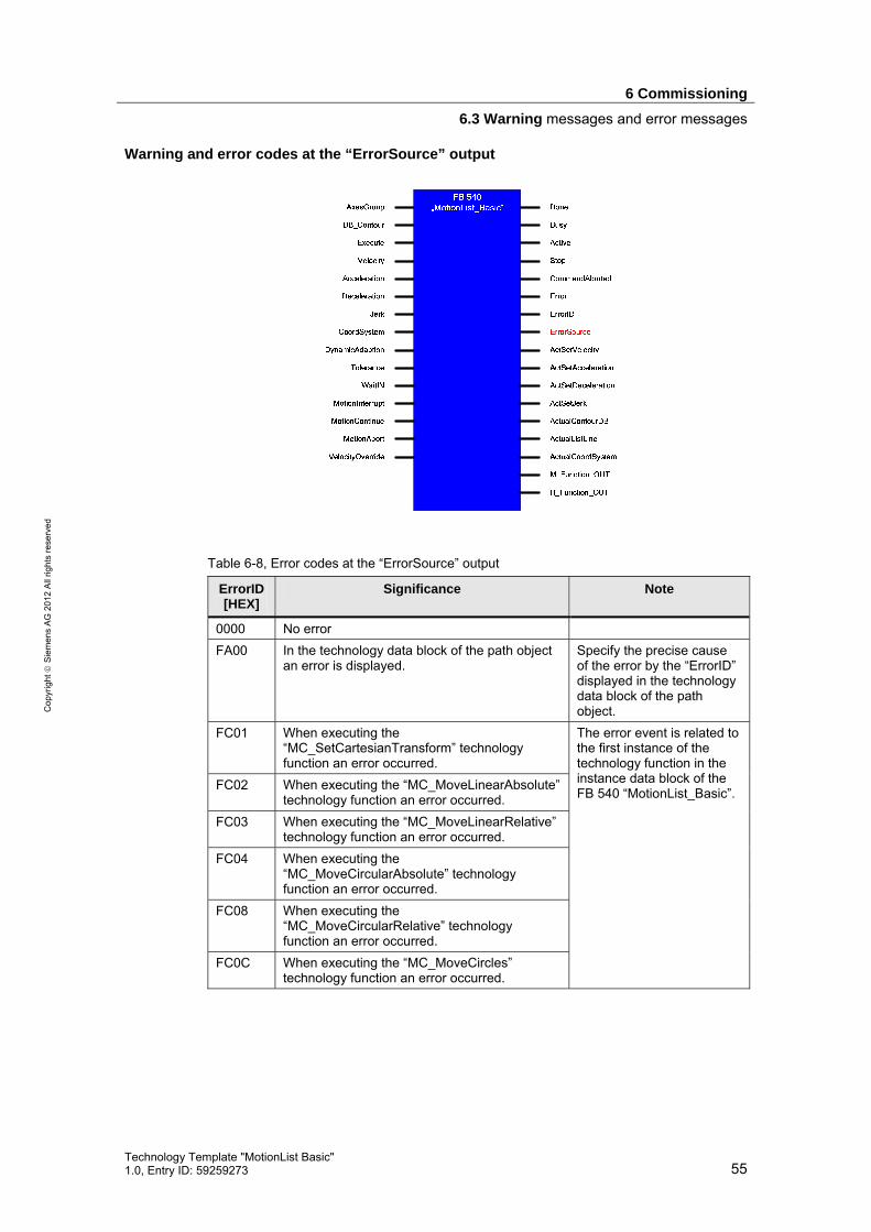
6 Commissioning
6.3 Warning messages and error messages
Technology Template "MotionList Basic" 1.0, Entry ID: 59259273 55
Cop
yrig
ht
Sie
men
s A
G 2
012
All
right
s re
serv
ed
Warning and error codes at the “ErrorSource” output
Table 6-8, Error codes at the “ErrorSource” output
ErrorID[HEX]
Significance Note
0000 No error FA00 In the technology data block of the path object
an error is displayed. Specify the precise cause of the error by the “ErrorID” displayed in the technology data block of the path object.
FC01 When executing the “MC_SetCartesianTransform” technology function an error occurred.
FC02 When executing the “MC_MoveLinearAbsolute” technology function an error occurred.
FC03 When executing the “MC_MoveLinearRelative” technology function an error occurred.
FC04 When executing the “MC_MoveCircularAbsolute” technology function an error occurred.
FC08 When executing the “MC_MoveCircularRelative” technology function an error occurred.
FC0C When executing the “MC_MoveCircles” technology function an error occurred.
The error event is related to the first instance of the technology function in the instance data block of the FB 540 “MotionList_Basic”.

6 Commissioning
6.3 Warning messages and error messages
56 Technology Template "MotionList Basic"
1.0, Entry ID: 59259273
Cop
yrig
ht
Sie
men
s A
G 2
012
All
right
s re
serv
ed
ErrorID[HEX]
Significance Note
FD01 When executing the “MC_SetCartesianTransform” technology function an error occurred.
FD02 When executing the “MC_MoveLinearAbsolute” technology function an error occurred.
FD03 When executing the “MC_MoveLinearRelative” technology function an error occurred.
FD04 When executing the “MC_MoveCircularAbsolute” technology function an error occurred.
FD08 When executing the “MC_MoveCircularRelative” technology function an error occurred.
FD0C When executing the “MC_MoveCircles” technology function an error occurred.
The error event is related to the second instance of the technology function in the instance data block of the FB 540 “MotionList_Basic”.
FE01 When executing the “MC_GroupStop” technology function an error occurred.
FE02 When executing the “MC_GroupInterrupt” technology function an error occurred.
FE03 When executing the “MC_GroupContinue” technology function an error occurred.
6.3.3 Warning and error code – FB 541 “HMI_List”
The block does not output any warning or error codes, but signals error events only via the “Error” output.
Figure 6-2 Warning and error codes on the FB 541 “HMI_List”

6 Commissioning
6.3 Warning messages and error messages
Technology Template "MotionList Basic" 1.0, Entry ID: 59259273 57
Cop
yrig
ht
Sie
men
s A
G 2
012
All
right
s re
serv
ed
The “Error” output is set by the block in the following situations: • When setting the “Generate_DB” input:
The desired data block could not be created via the SFC 22 “CREATE_DB” because, for example, the specified DB number already existed or is not permitted.
• When setting the “Open_DB” input: The desired data block could not be opened because the desired data block does not have the defined length (3200 bytes) of a contour data block or the SFC 24 “TEST_DB” could not be performed properly.
• When setting the “Save_DB” input: When setting the input, the “Save under…” function was used whilst specifying a changed DB number. However, the desired data block could not be created via the SFC 22 “CREATE_DB” because, for example, the specified DB number already existed or is not permitted.
6.3.4 Warning and error codes – FB 542 “HMI_3D_Movement”
The block does not output warning and error codes
Figure 6-3 Warning and error codes on the FB 542 “HMI_3D_Movement”
6.3.5 Warning and error codes – FB 543 “HMI_DB_Explorer”
The block does not output any warning or error codes, but signals error events only via the “Error” output.
Figure 6-4 Warning and error codes on the FB 543 “HMI_DB_Explorer”
If more than 100 data blocks with a size of 3200 bytes (contour data blocks) are found in the RAM of the CPU, the “Error” output is set by the block.
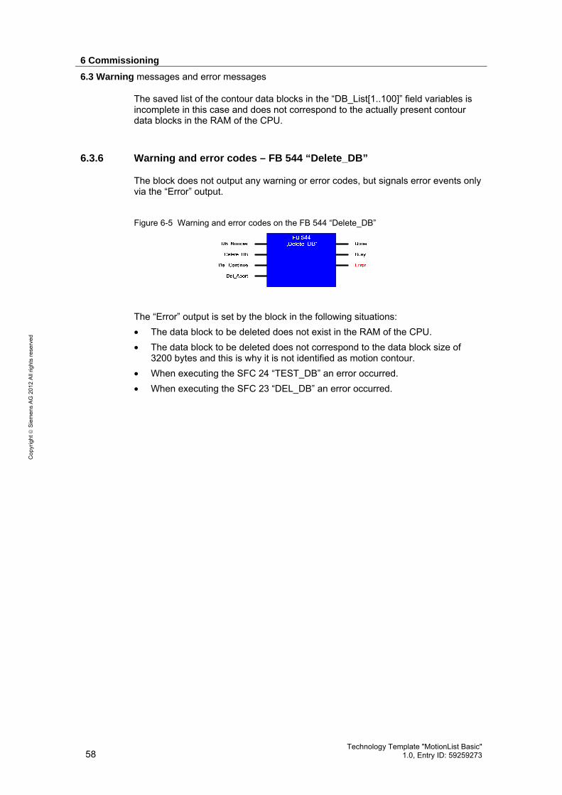
6 Commissioning
6.3 Warning messages and error messages
58 Technology Template "MotionList Basic"
1.0, Entry ID: 59259273
Cop
yrig
ht
Sie
men
s A
G 2
012
All
right
s re
serv
ed
The saved list of the contour data blocks in the “DB_List[1..100]” field variables is incomplete in this case and does not correspond to the actually present contour data blocks in the RAM of the CPU.
6.3.6 Warning and error codes – FB 544 “Delete_DB”
The block does not output any warning or error codes, but signals error events only via the “Error” output.
Figure 6-5 Warning and error codes on the FB 544 “Delete_DB”
The “Error” output is set by the block in the following situations: • The data block to be deleted does not exist in the RAM of the CPU. • The data block to be deleted does not correspond to the data block size of
3200 bytes and this is why it is not identified as motion contour. • When executing the SFC 24 “TEST_DB” an error occurred. • When executing the SFC 23 “DEL_DB” an error occurred.

7 Command Overview
7.1 Commands available in the technology template
Technology Template "MotionList Basic" 1.0, Entry ID: 59259273 59
Cop
yrig
ht
Sie
men
s A
G 2
012
All
right
s re
serv
ed
7 Command Overview
7.1 Commands available in the technology template
In the list below, you find all existing commands in the technology template that can be used in the “MotionList Basic” in table form.
Table 7-1 Commands available in the technology template
Parameter
EndPoint AuxPoint
ID Command
X Y Z X Y Z
H fct.
M fct.
0 NOP
1 SetCartesianTransform Trans X
Trans Y
Trans Z
Rot X
Rot Y
Rot Z
2 MoveLinearAbsolute Posi-tion X
Posi-tion Y
Posi-tion Z
H func-tion
M func-tion
3 MoveLinearRelative Dis-tance
X Dis-
tance Y
Dis-tance
Z H
func-tion
M func-tion
4 MoveCircAbs_AE End Point
X End Point
X End Point
X Aux
Point X
Aux Point
Y Aux
Point Z
H func-tion
M func-tion
5 MoveCircAbs_CE_S End Point
X End Point
X End Point
X End Point
X End Point
X End Point
X H
func-tion
M func-tion
6 MoveCircAbs_CE_L End Point
X End Point
X End Point
X Aux
Point X
Aux Point
Y Aux
Point Z
H func-tion
M func-tion
8 MoveCircRel_AE Dis-tance
X Dis-
tance Y
Dis-tance
Z Aux
Point X
Aux Point
Y Aux
Point Z
H func-tion
M func-tion
9 MoveCircRel_CE_S Dis-tance
X Dis-
tance Y
Dis-tance
Z Aux
Point X
Aux Point
Y Aux
Point Z
H func-tion
M func-tion
10 MoveCircRel_CE_L Dis-tance
X Dis-
tance Y
Dis-tance
Z Aux
Point X
Aux Point
Y Aux
Point Z
H func-tion
M func-tion
12 MoveCirclesAbsolute Arc CenterPoint
X CenterPoint
Y Center Point
Z H
func-tion
M func-tion
13 MoveCirclesRelative Arc Dis-tance C_X
Dis-tance C_Y
Dis-tance C_Z
H func-tion
M func-tion
16 ExactStop_ON
17 ExactStop_OFF
18 WaitIN
H func-tion
M func-tion
19 WaitTime Wait Time
[s] H
func-tion
M func-tion
22 SetPlane_XY
23 SetPlane_YZ
24 SetPlane_ZX

7 Command Overview
7.2 Motion commands
60 Technology Template "MotionList Basic"
1.0, Entry ID: 59259273
Cop
yrig
ht
Sie
men
s A
G 2
012
All
right
s re
serv
ed
Parameter
EndPoint AuxPoint
ID Command
X Y Z X Y Z
H fct.
M fct.
25 SetTransitionMode
Transi tion
Mode Transi
tion Mode
26 CallContourDB
DB Num-ber
27 SetVelocity
Velocity
28 SetAcceleration
Acceleration
29 SetDeceleration
Deceleration
30 SetJerk
Jerk
31 SetTolerance
Tolerance
32 SetCoordSystem_BCS
33 SetCoordSystem_OCS
34 JumpToLine
Desti-nation Line
99 EndOfList
A detailed explanation of the individual commands can be found in the following chapters.
7.2 Motion commands
Via the motion commands individual contour elements or the traverse blocks of the contour can be defined. The motion commands are referenced to technology functions for path objects form the S7 technology. This is why they behave like the functions mentioned in the manual for the S7 technology. This is why the parameters of the corresponding technology functions are specified for the parameter description of the commands in the following chapters.
Note The graphics to simplify the traverse motions are only displayed in the X-Z plane (2D) to achieve better readability, although most commands can also be used in space (3D).

7 Command Overview
7.2 Motion commands
Technology Template "MotionList Basic" 1.0, Entry ID: 59259273 61
Cop
yrig
ht
Sie
men
s A
G 2
012
All
right
s re
serv
ed
7.2.1 “SetCartesianTransform”
Command to move and rotate the object coordinate system (OCS) in relation to the basic coordinate system (BCS).
Table 7-2 Parameter assignment
ID =1 SetCartesianTransform
EndPoint AuxPoint
X Y Z X Y Z H fct. M fct.
Trans X
Trans Y
Trans Z
Rot X
Rot Y
Rot Z
Technology function used FB 480 “MC_SetCartesianTransform”
The parameters of the command always have an absolute effect in relation to the basic coordinate system (BCS). In order to revoke a moving or rotating of the object coordinate system (OCS) that has already been carried out, all parameters have to be assigned with the value 0.000. The moving and rotating the object coordinate system (OCS) in relation to the basic coordinate system (BCS) takes place in the following sequence:
– moving in X, Y and Z direction – rotation around X axis – rotation around Y axis – rotation around Z axis
Note If this command is used for the definition of motion blocks, the object coordinate system (OCS) also has to be selected via the “CoordSystem” parameter on the FB 540 “MotionList_Basic” to process the motion list or the coordinate system has to be switched via the “SetCoordSystem_OCS” command. Otherwise this command will be without consequence for the processing of the motion list.
Note The settings of the “SetCartesianTransform” command are self-holding, i.e. they remain active in the controller even after the motion program has finished. This has to be taken into account when using the object coordinate system (OCS) after the use of this command.
If the “SetCartesianTransform” command is to be cancelled, the command has to be called again with the parameter values 0,000 for all settings.
7.2.2 "MoveLinearAbsolute"
Command to generate a linear traverse motion along a plane, whilst specifying an absolute target position.

7 Command Overview
7.2 Motion commands
62 Technology Template "MotionList Basic"
1.0, Entry ID: 59259273
Cop
yrig
ht
Sie
men
s A
G 2
012
All
right
s re
serv
ed
Table 7-3 Parameter assignment
ID =2 MoveLinearAbsolute
EndPoint AuxPoint
X Y Z X Y Z H fct. M fct.
PositionX
Position Y
PositionZ H
function M
function
Technology function used FB 484 “MC_MoveLinearAbsolute”
Figure 7-1 Parameter assignment for the traverse motion
7.2.3 “MoveLinearRelative”
Command to generate a linear traverse motion along a plane whilst specifying the distance of the target position in relation to the start position of the motion.
Table 7-4 Parameter assignment
ID =3 MoveLinearRelative
EndPoint AuxPoint
X Y Z X Y Z H fct. M fct.
DistanceX
Distance Y
DistanceZ H
function M
function
Technology function used FB 485 “MC_MoveLinearRelative”
Figure 7-2 Parameter assignment for the traverse motion

7 Command Overview
7.2 Motion commands
Technology Template "MotionList Basic" 1.0, Entry ID: 59259273 63
Cop
yrig
ht
Sie
men
s A
G 2
012
All
right
s re
serv
ed
7.2.4 “MoveCircAbs_AE”
Command to generate a circular traverse motion along a circular path whilst specifying an absolute end point and the absolute position of an intermediate point that is located on the desired circular path. Via the position of the intermediate point, the radius of the circular arc as well as the selection of the one of the two possible arc segments is specified between the start and end point.
Table 7-5 Parameter assignment
ID =4 MoveCircAbs_AE
EndPoint AuxPoint
X Y Z X Y Z H fct. M fct.
End Point
X
End Point
X
End Point
X
Aux Point
X
Aux Point
Y
Aux Point
Z
H function
M function
Technology function used FB 486 “MC_MoveCircularAbsolute”
Figure 7-3 Parameter assignment for the traverse motion
7.2.5 “MoveCircAbs_CE_S”
Command to generate a circular traverse motion along a short segment of a circular arc whilst specifying an absolute end point and the absolute position of the center point of the circle.
Table 7-6 Parameter assignment
ID =5 MoveCircAbs_CE_S
EndPoint AuxPoint
X Y Z X Y Z H fct. M fct.
End Point
X
End Point
X
End Point
X
Center Point
X
Center Point
Y
Center Point
Z
H function
M function
Technology function used FB 486 “MC_MoveCircularAbsolute”

7 Command Overview
7.2 Motion commands
64 Technology Template "MotionList Basic"
1.0, Entry ID: 59259273
Cop
yrig
ht
Sie
men
s A
G 2
012
All
right
s re
serv
ed
Figure 7-4 Parameter assignment for the traverse motion
Note To move along semi circles, please use the following commands:
• “MoveCircAbs_AE” Definition of the circular traverse motion via start, end and an intermediate point that is located on the desired arc segment that is to be traversed.
• “MoveCirclesAbsolute“ Definition of the circular traverse motion via the center point of the circle and the specification of the aperture angle of the arc segment starting from the start point.
Note To execute the command, the internally calculated radius between start point and center point of the circle or between the end point and the center point of the circle, has to be located within the tolerance defined within the “SetTolerance” command.
7.2.6 “MoveCircAbs_CE_L”
Command to generate a circular traverse motion along a long segment of a circular arc whilst specifying an absolute end point and the absolute position of the center point of the circle.
Table 7-7 Parameter assignment
ID =6 MoveCircAbs_CE_L
EndPoint AuxPoint
X Y Z X Y Z H fct. M fct.
End Point
X
End Point
X
End Point
X
Center Point
X
Center Point
Y
Center Point
Z
H function
M function
Technology function used FB 486 “MC_MoveCircularAbsolute”

7 Command Overview
7.2 Motion commands
Technology Template "MotionList Basic" 1.0, Entry ID: 59259273 65
Cop
yrig
ht
Sie
men
s A
G 2
012
All
right
s re
serv
ed
Figure 7-5 Parameter assignment for the traverse motion
Note To move along semi circles, please use the following commands:
• “MoveCircAbs_AE” Definition of the circular traverse motion via start, end and an intermediate point that is located on the desired arc segment that is to be traversed.
• “MoveCirclesAbsolute“ Definition of the circular traverse motion via the center point of the circle and the specification of the aperture angle of the arc segment starting from the start point.
Note To execute the command, the internally calculated radius between start point and center point of the circle or between the end point and the center point of the circle, has to be located within the tolerance defined within the “SetTolerance” command.
7.2.7 “MoveCircRel_AE”
Command to generate a circular traverse motions along a circular path whilst specifying the distance of the end point of the circular segment in relation to the start point of the circular segment and the absolute position of an intermediate point that is located on the desired circular path. Via the position of the intermediate point, the radius of the circular arc and the selection of one of the two possible arc segments is specified between the start and end point.
Table 7-8 Parameter assignment
ID =8 MoveCircRel_AE
EndPoint AuxPoint
X Y Z X Y Z H fct. M fct.
DistanceX
Distance Y
DistanceZ
Aux Point
X
Aux Point
Y
Aux Point
Z
H function
M function
Technology function used FB 487 “MC_MoveCircularRelative”

7 Command Overview
7.2 Motion commands
66 Technology Template "MotionList Basic"
1.0, Entry ID: 59259273
Cop
yrig
ht
Sie
men
s A
G 2
012
All
right
s re
serv
ed
Figure 7-6 Parameter assignment for the traverse motion
7.2.8 “MoveCircRel_CE_S”
Command to generate a circular traverse motion along a short segment of a circular path whilst specifying the distance of the end point of the circular segment in relation to the start point of the circular segment and the absolute position of the center of the circle.
Table 7-9 Parameter assignment
ID =9 MoveCircRel_CE_S
EndPoint AuxPoint
X Y Z X Y Z H fct. M fct.
DistanceX
Distance Y
DistanceZ
Center Point
X
Center Point
Y
Center Point
Z
H function
M function
Technology function used FB 487 “MC_MoveCircularRelative”
Figure 7-7 Parameter assignment for the traverse motion

7 Command Overview
7.2 Motion commands
Technology Template "MotionList Basic" 1.0, Entry ID: 59259273 67
Cop
yrig
ht
Sie
men
s A
G 2
012
All
right
s re
serv
ed
Note To move along semi circles, please use the following commands:
• “MoveCircRel_AE” Definition of the circular traverse motion via start, end and an intermediate point that is located on the desired arc segment that is to be traversed.
• “MoveCirclesRelative“ Definition of the circular traverse motion via the distance of the center point of the circle to the start point of the arc segment and the specification of the aperture angle of the arc segment, starting from the arc segment.
Note To execute the command, the internally calculated radius between start point and center point of the circle or between the end point and the center point of the circle, has to be located within the tolerance defined within the “SetTolerance” command.
7.2.9 “MoveCircRel_CE_L”
Command to generate a circular traverse motion along a long segment of a circular path whilst specifying the distance of the end point of the circular segment in relation to the start point of the circular segment and the absolute position of the center point of the circle.
Table 7-10 Parameter assignment
ID =10 MoveCircRel_CE_L
EndPoint AuxPoint
X Y Z X Y Z H fct. M fct.
DistanceX
Distance Y
DistanceZ
Center Point
X
Center Point
Y
Center Point
Z
H function
M function
Technology function used FB 487 “MC_MoveCircularRelative”
Figure 7-8 Parameter assignment for the traverse motion

7 Command Overview
7.2 Motion commands
68 Technology Template "MotionList Basic"
1.0, Entry ID: 59259273
Cop
yrig
ht
Sie
men
s A
G 2
012
All
right
s re
serv
ed
Note To move along semi circles, please use the following commands:
• “MoveCircRel_AE” Definition of the circular traverse motion via start, end and an intermediate point that is located on the desired arc segment that is to be traversed.
• “MoveCirclesRelative“ Definition of the circular traverse motion via the distance of the center point of the circle to the start point of the arc segment and the specification of the aperture angle of the arc segment, starting from the arc segment.
Note To execute the command, the internally calculated radius between start point and center point of the circle or between the end point and the center point of the circle, has to be located within the tolerance defined within the “SetTolerance” command.
7.2.10 “MoveCirclesAbsolute”
Command to generate a circular traverse motion in a specified plane of the coordinate system whilst specifying the absolute position of the center point of the circle and the aperture angle. Via this command, circular traverse motions with “several revolutions” can be generated by specifying an aperture angle > 360°. The direction of motion of the circular traverse motion in the specified plane is specified via the sign of the aperture angle.
Table 7-11 Parameter assignment
ID =12 MoveCirclesAbsolute
EndPoint AuxPoint
X Y Z X Y Z H fct. M fct.
Arc Center Point
X
Center Point
Y
Center Point
Z
H function
M function
Technology function used FB 496 “MC_MoveCirlces”
Figure 7-9 Parameter assignment for the traverse motion

7 Command Overview
7.2 Motion commands
Technology Template "MotionList Basic" 1.0, Entry ID: 59259273 69
Cop
yrig
ht
Sie
men
s A
G 2
012
All
right
s re
serv
ed
Note The plane in which the circular motion is to be traversed, is specified via the “SetPlane_XY”, “SetPlane_YZ” and “SetPlane_ZX”.
An adjustment of the position of the planes of the object coordinate system (OCS) in space by moving and rotating in relation to the basic coordinate system (BCS) is possible via the “SetCartesianTransform” command.
7.2.11 “MoveCirclesRelative”
Command to generate a circular traverse motion in a predefined plane of the coordinate system whilst specifying the distance of the center point of the circular arc in relation to the start point of the circular arc and of the aperture angle. Via this command, circular traverse motions with “several revolutions” can be generated by specifying an aperture angle > 360°. The direction of motion of the circular traverse motion in the specified plane is specified via the sign of the aperture angle.
Table 7-12 Parameter assignment
ID =13 MoveCirclesRelative
EndPoint AuxPoint
X Y Z X Y Z H fct. M fct.
Arc DistanceCenter Point
X
DistanceCenter Point
X
DistanceCenter Point
X
H function
M function
Technology function used FB 496 “MC_MoveCirlces”
Figure 7-10 Parameter assignment for the traverse motion
Note The plane in which the circular motion is to be traversed, is specified via the “SetPlane_XY”, “SetPlane_YZ” and “SetPlane_ZX”.
An adjustment of the position of the planes of the object coordinate system (OCS) in space by moving and rotating in relation to the basic coordinate system (BCS) is possible via the “SetCartesianTransform” command.

7 Command Overview
7.3 System commands
70 Technology Template "MotionList Basic"
1.0, Entry ID: 59259273
Cop
yrig
ht
Sie
men
s A
G 2
012
All
right
s re
serv
ed
7.3 System commands
Special settings and parameters of the technology functions located behind the motion commands in the motion list can be defined and changed via the system commands.
Note The settings and parameters in the positioning program are self-holding, i.e. once they have been set by the commands listed here, they remain valid for the following motion commands until they are again overwritten by a system command.
Note The default settings of selected parameters can be specified via the input parameter of the FB 540 "MotionList_Basic“.
7.3.1 “ExactStop_ON”
Command to attach the following traverse motions from this command onwards. On the technology functions used for the motion commands, the value 1 (attach) is entered for the “BufferMode” parameter.
Table 7-13 Parameter assignment
ID =16 ExactStop_ON
EndPoint AuxPoint
X Y Z X Y Z H fct. M fct.
Technology function used FB 484 “MC_MoveLinearAbsolute” FB 485 “MC_MoveLinearRelative” FB 486 “MC_MoveCircularAbsolute” FB 487 “MC_MoveCircularRelative” FB 496 “MC_MoveCirlces”
7.3.2 “ExactStop_OFF”
Command to position the traverse motions approximately from this command onward. On the technology functions used for the motion commands, the value 2 (approximate positioning) is entered for the “BufferMode” parameter.

7 Command Overview
7.3 System commands
Technology Template "MotionList Basic" 1.0, Entry ID: 59259273 71
Cop
yrig
ht
Sie
men
s A
G 2
012
All
right
s re
serv
ed
Note For linear traverse motions the setting above the “SetTransitionMode” command also has to be additionally observed to precisely define the transmission behavior between the two motion processes.
Table 7-14 Parameter assignment
ID =17 ExactStop_OFF
EndPoint AuxPoint
X Y Z X Y Z H fct. M fct.
Technology function used FB 484 “MC_MoveLinearAbsolute” FB 485 “MC_MoveLinearRelative” FB 486 “MC_MoveCircularAbsolute” FB 487 “MC_MoveCircularRelative” FB 496 “MC_MoveCirlces”
7.3.3 “WaitIN”
Command to interrupt the traverse motion defined in the “MotionList Basic”. The motion is interrupted until the “WaitIN” input has been set on the FB 540 “MotionList_Basic” block of the technology template. If an input has already been set when processing the command, the traverse motion is not interrupted and the transition defined in the “MotionList Basic” is executed to the next traverse motion.
Table 7-15 Parameter assignment
ID =18 WaitIN
EndPoint AuxPoint
X Y Z X Y Z H fct. M fct.
H function
M function
Technology function used -
7.3.4 “WaitTime”
Command to interrupt the traverse motion defined in the “MotionList Basic”. The motion is interrupted for the time specified in seconds in the command before it is continued with the next command from the “MotionList Basic”. The lapse of the defined time only starts when the previous traverse motion has come to a standstill.

7 Command Overview
7.3 System commands
72 Technology Template "MotionList Basic"
1.0, Entry ID: 59259273
Cop
yrig
ht
Sie
men
s A
G 2
012
All
right
s re
serv
ed
Table 7-16 Parameter assignment
ID =19 WaitTime
EndPoint AuxPoint
X Y Z X Y Z H fct. M fct.
Wait Time
[s] H
function M
function
Technology function used SFB 4 “TON” (system function of the CPU)
7.3.5 “SetPlane_XY”
Command to specify the coordinate system plane in which the circular motions are to be executed via the commands “MoveCirclesAbsolute” and “MoveCirclesRelative”. The circular motion via “MoveCirclesAbsolute” and “MoveCirclesRelative” is executed in the X-Y plane of the coordinate system.
Table 7-17 Parameter assignment
ID =22 SetPlane_XY
EndPoint AuxPoint
X Y Z X Y Z H fct. M fct.
Technology function used FB 496 “MC_MoveCirlces”
Note If the circular motion is to be executed generally in space via the commands “MoveCirclesAbsolute” and “MoveCirclesRelative”, an adjustment of the position of the plane of the object coordinate system (OCS) is additionally required in space by moving and rotating in relation to the basic coordinate system (BCS) via the “SetCartesianTransform” command.
7.3.6 “SetPlane_YZ”
Command to specify the coordinate system plane in which the circular motions are to be executed via the commands “MoveCirclesAbsolute” and “MoveCirclesRelative”. The circular motion via “MoveCirclesAbsolute” and “MoveCirclesRelative” is executed in the Y-Z plane of the coordinate system.

7 Command Overview
7.3 System commands
Technology Template "MotionList Basic" 1.0, Entry ID: 59259273 73
Cop
yrig
ht
Sie
men
s A
G 2
012
All
right
s re
serv
ed
Table 7-18 Parameter assignment
ID =23 SetPlane_YZ
EndPoint AuxPoint
X Y Z X Y Z H fct. M fct.
Technology function used FB 496 “MC_MoveCirlces”
Note If the circular motion is to be executed generally in space via the commands “MoveCirclesAbsolute” and “MoveCirclesRelative”, an adjustment of the position of the plane of the object coordinate system (OCS) is additionally required in space by moving and rotating in relation to the basic coordinate system (BCS) via the “SetCartesianTransform” command.
7.3.7 “SetPlane_ZX”
Command to specify the coordinate system plane in which the circular motions are to be executed via the commands “MoveCirclesAbsolute” and “MoveCirclesRelative”. The circular motion via “MoveCirclesAbsolute” and “MoveCirclesRelative” is executed in the Z-X plane of the coordinate system.
Table 7-19 Parameter assignment
ID =24 SetPlane_ZX
EndPoint AuxPoint
X Y Z X Y Z H fct. M fct.
Technology function used FB 496 “MC_MoveCirlces”
Note If the circular motion is to be executed generally in space via the commands “MoveCirclesAbsolute” and “MoveCirclesRelative”, an adjustment of the position of the plane of the object coordinate system (OCS) is additionally required in space by moving and rotating in relation to the basic coordinate system (BCS) via the “SetCartesianTransform” command.
7.3.8 “SetTransitionMode”
Command to specify the transition mode between two linear traverse motions.

7 Command Overview
7.3 System commands
74 Technology Template "MotionList Basic"
1.0, Entry ID: 59259273
Cop
yrig
ht
Sie
men
s A
G 2
012
All
right
s re
serv
ed
Note The settings performed here are only active on the linear traverse motion if the “ExactStop_OFF” command was enabled in addition.
Table 7-20 Parameter assignment
ID =25 SetTransitionMode
EndPoint AuxPoint
X Y Z X Y Z H fct. M fct.
Transi-
tion Mode
Transi-tion
Para-meter
Technology function used FB 484 “MC_MoveLinearAbsolute” FB 485 “MC_MoveLinearRelative”
7.3.9 CallContourDB
Command to call another data block in which a contour or a motion list is also stored (nested call). The contour in the currently active data block is interrupted at this place of the command and after processing the data block defined in the command, continued with the next command.
Table 7-21 Parameter assignment
ID =26 CallContourDB
EndPoint AuxPoint
X Y Z X Y Z H fct. M fct.
DB number
Technology function used -
Note The maximum nesting depth for the call of another data block from a motion list is 10.
7.3.10 SetVelocity
Command to change the defined speed for the execution of the traverse motion. The speed defined via this command remains the same until the next call of this command. The setting on the “Velocity” parameter of the FB 540 “MotionList_Basic” is used as the basic setting for the defined speed of the traverse motion.

7 Command Overview
7.3 System commands
Technology Template "MotionList Basic" 1.0, Entry ID: 59259273 75
Cop
yrig
ht
Sie
men
s A
G 2
012
All
right
s re
serv
ed
Table 7-22 Parameter assignment
ID =27 SetVelocity
EndPoint AuxPoint
X Y Z X Y Z H fct. M fct.
Velocity
Technology function used FB 484 “MC_MoveLinearAbsolute” FB 485 “MC_MoveLinearRelative” FB 486 “MC_MoveCircularAbsolute” FB 487 “MC_MoveCircularRelative” FB 496 “MC_MoveCirlces”
Note If the standard value stored in S7T Config is to be used as speed, the value -1 has to be transmitted as speed via this command.
7.3.11 SetAcceleration
Command to change the defined acceleration for the execution of the traverse motion. The acceleration defined via this command remains the same until the next call of this command. The setting on the “Acceleration” parameter of the FB 540 “MotionList_Basic” is used as the basic setting for the defined acceleration of the traverse motion.
Table 7-23 Parameter assignment
ID =28 SetAcceleration
EndPoint AuxPoint
X Y Z X Y Z H fct. M fct.
Acceleration
Technology function used FB 484 “MC_MoveLinearAbsolute” FB 485 “MC_MoveLinearRelative” FB 486 “MC_MoveCircularAbsolute” FB 487 “MC_MoveCircularRelative” FB 496 “MC_MoveCirlces”
Note If the standard value stored in S7T Config is to be used as acceleration, the value -1 has to be transmitted as acceleration via this command.

7 Command Overview
7.3 System commands
76 Technology Template "MotionList Basic"
1.0, Entry ID: 59259273
Cop
yrig
ht
Sie
men
s A
G 2
012
All
right
s re
serv
ed
7.3.12 SetDeceleration
Command to change the defined deceleration for the execution of the traverse motion. The deceleration defined via this command remains the same until the next call of this command. The setting on the “Deceleration” parameter of the FB 540 “MotionList_Basic” is used as the basic setting for the defined deceleration of the traverse motion.
Table 7-24 Parameter assignment
ID =29 SetDeceleration
EndPoint AuxPoint
X Y Z X Y Z H fct. M fct.
Deceleration
Technology function used FB 484 “MC_MoveLinearAbsolute” FB 485 “MC_MoveLinearRelative” FB 486 “MC_MoveCircularAbsolute” FB 487 “MC_MoveCircularRelative” FB 496 “MC_MoveCirlces”
Note If the standard value stored in S7T Config is to be used as deceleration, the value -1 has to be transmitted as deceleration via this command.
7.3.13 SetJerk
Command to change the defined jerk for the execution of the traverse motion. The jerk defined via this command remains the same until the next call of this command. The setting on the “jerk” parameter of the FB 540 “MotionList_Basic” is used as the basic setting for the defined jerk of the traverse motion.
Table 7-25 Parameter assignment
ID =30 SetJerk
EndPoint AuxPoint
X Y Z X Y Z H fct. M fct.
Jerk
Technology function used FB 484 “MC_MoveLinearAbsolute” FB 485 “MC_MoveLinearRelative” FB 486 “MC_MoveCircularAbsolute” FB 487 “MC_MoveCircularRelative” FB 496 “MC_MoveCirlces”

7 Command Overview
7.3 System commands
Technology Template "MotionList Basic" 1.0, Entry ID: 59259273 77
Cop
yrig
ht
Sie
men
s A
G 2
012
All
right
s re
serv
ed
Note If the standard value stored in S7T Config is to be used as jerk, the value -1 has to be transmitted as jerk via this command.
7.3.14 SetTolerance
Command to set the permitted deviation of the distances between start point and intermediate point and between end point and center point for the definition of a circular motion. The permissible tolerance is to be entered by a factor of 1000 larger than the tolerance in the unit of measure used.
Table 7-26 Parameter assignment
ID =31 SetTolerance
EndPoint AuxPoint
X Y Z X Y Z H fct. M fct.
Tolerance
Technology function used FB 486 “MC_MoveCircularAbsolute” FB 487 “MC_MoveCircularRelative”
7.3.15 SetCoordSystem_BCS
Command to activate the basic coordinate system (BCS). The position specifications of all the following commands are related to the basic coordinate system.
Table 7-27 Parameter assignment
ID =32 SetCoordSystem_BCS
EndPoint AuxPoint
X Y Z X Y Z H fct. M fct.
Technology function used FB 484 “MC_MoveLinearAbsolute” FB 485 “MC_MoveLinearRelative” FB 486 “MC_MoveCircularAbsolute” FB 487 “MC_MoveCircularRelative” FB 496 “MC_MoveCirlces”
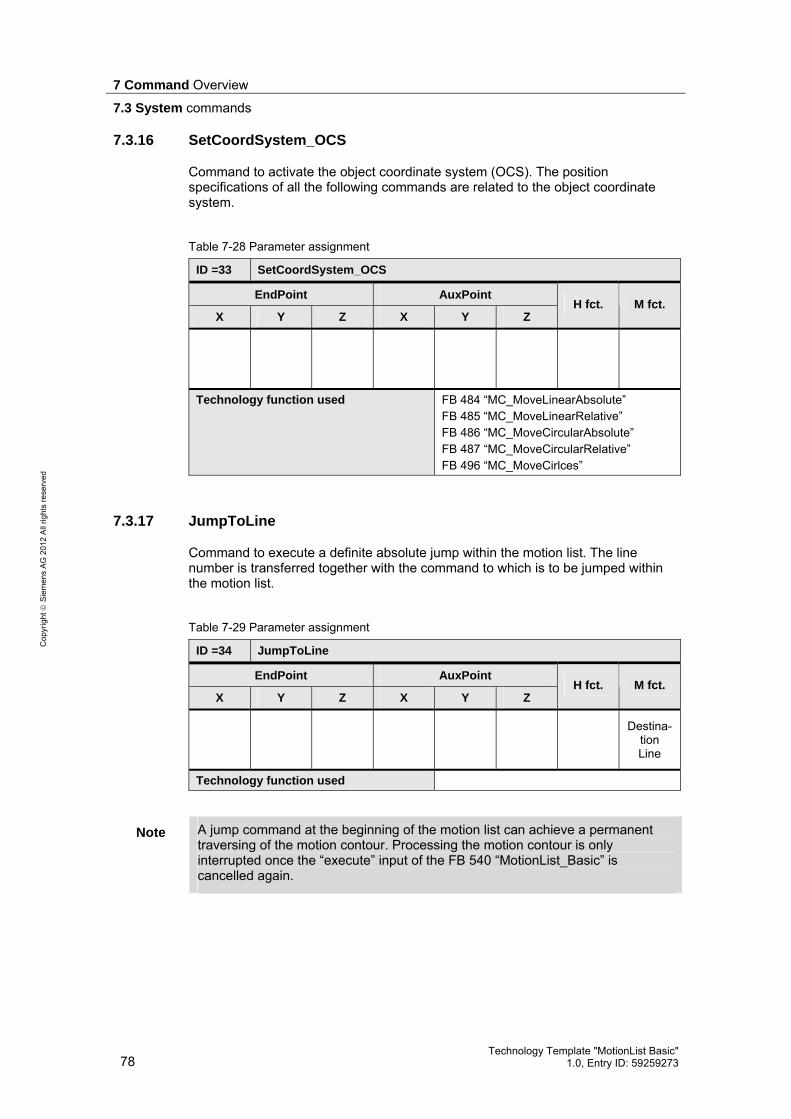
7 Command Overview
7.3 System commands
78 Technology Template "MotionList Basic"
1.0, Entry ID: 59259273
Cop
yrig
ht
Sie
men
s A
G 2
012
All
right
s re
serv
ed
7.3.16 SetCoordSystem_OCS
Command to activate the object coordinate system (OCS). The position specifications of all the following commands are related to the object coordinate system.
Table 7-28 Parameter assignment
ID =33 SetCoordSystem_OCS
EndPoint AuxPoint
X Y Z X Y Z H fct. M fct.
Technology function used FB 484 “MC_MoveLinearAbsolute” FB 485 “MC_MoveLinearRelative” FB 486 “MC_MoveCircularAbsolute” FB 487 “MC_MoveCircularRelative” FB 496 “MC_MoveCirlces”
7.3.17 JumpToLine
Command to execute a definite absolute jump within the motion list. The line number is transferred together with the command to which is to be jumped within the motion list.
Table 7-29 Parameter assignment
ID =34 JumpToLine
EndPoint AuxPoint
X Y Z X Y Z H fct. M fct.
Destina-
tion Line
Technology function used
Note A jump command at the beginning of the motion list can achieve a permanent traversing of the motion contour. Processing the motion contour is only interrupted once the “execute” input of the FB 540 “MotionList_Basic” is cancelled again.

7 Command Overview
7.4 Additional commands
Technology Template "MotionList Basic" 1.0, Entry ID: 59259273 79
Cop
yrig
ht
Sie
men
s A
G 2
012
All
right
s re
serv
ed
7.4 Additional commands
The additional commands provide functions for the list management within the contour table.
7.4.1 “NOP”
Command to generate blank lines or placeholder lines to expand later commands within the contour table. Blank lines are ignored when processing the contour table and the technology template instantly jumps to the next command line.
Table 7-30 Parameter assignment
ID =0 NOP
EndPoint AuxPoint
X Y Z X Y Z H fct. M fct.
Technology function used
7.4.2 “EndOfList”
Command to mark the end of the contour table. If there is no “EndOfList” command in the table, the contour table is processed until the last line. Via this command the processing of the contour table can be ended early, e.g. when testing the motion program in small sections.
Table 7-31 Parameter assignment
ID =99 EndOfList
EndPoint AuxPoint
X Y Z X Y Z H fct. M fct.
Technology function used

8 Operation
8.1 Control via the block interface
80 Technology Template "MotionList Basic"
1.0, Entry ID: 59259273
Cop
yrig
ht
Sie
men
s A
G 2
012
All
right
s re
serv
ed
8 Operation The operation of the “MotionList Basic” technology template can be performed in two ways: • Via the interface of the function blocks:
This type of control is mainly considered when the “MotionList Basic” technology template is to be controlled via other blocks of the user program.
• Via the HMI user interface included in delivery: This type of control is used when the “MotionList Basic” technology template in the technology CPU is to be used for the creation, management and execution of the traverse motion, based on a motion contour.
8.1 Control via the block interface
When controlling the “MotionList Basic” technology template via the block interface, the respective block of the technology template has to be selected, depending on the desired functionality: • Motion functions
To execute a traverse motion stored in a contour data block, the FB 540 “MotionList_Basic” is used.
• Management functions
– Manipulating contour data blocks: To change one of the motion contours stored in a contour data block, it is usually written from the user program straight into this data block. The assignment of the individual parameter values in the contour data block is performed according to UDT 541 “ContourListData” or according to UDT 540 “ContourList”. The FB 541 “HMI_List” can be used in the same way; here the access to the data of the contour data block is performed via the internal “ConturList” data structure of the block. The operation is the same as the operation via the HMI user interface, i.e. the contour data block has to be opened and closed and “without page change” a maximum of 10 connected entries of the contour block can be changed.
– Delete contour data blocks: To delete contour data blocks in the main memory of the technology CPU, use the FB 544 “Delete_DB”. Via this block it is ensured that only data blocks with a size of 3200 bytes can be deleted from the main memory of the CPU.
– Searching for contour data blocks: To search contour data blocks in the main memory of the technology CPU, use the FB 543 “HMI_DB_Explorer”. The block searches data blocks with a size of 3200 bytes and stores the detected data block numbers in the internal data structure “DB_List” of the block.

8 Operation
8.1 Control via the block interface
Technology Template "MotionList Basic" 1.0, Entry ID: 59259273 81
Cop
yrig
ht
Sie
men
s A
G 2
012
All
right
s re
serv
ed
8.1.1 Motion functions
To execute a traverse motion stored in a contour data block with the FB 540 “MotionList_Basic” proceed as follows:
Table 8-1
Steps Action Note
Preparations 1. Define the number of the path object
that is to be used for the axis movement via “AxisGroup”
2. Define the number of the contour data block in which the motion contour is stored via "DB_Contour".
There will be no plausibility check for the specified data block. In order to avoid undesired motions, only enter the data blocks that contain a motion contour.
3. Define the default values for the technology functions via the block inputs “velocity” to “tolerance” that are used within the block to execute the traverse motion.
The input parameters serve as default values and in most cases can be overwritten via commands within the contour of the contour data block.
Start traverse motion 4. Start the traverse motion by setting
the “execute” input. The traverse motion is only executed if the “execute” input is set to true. The traverse motion is interrupted if the “execute” input is reset.
Influencing the traverse motion 5. Via a rising edge on the
“MotionInterrupt” input the traverse motion can be continuously interrupted.
6. Via a rising edge on the “MotionContinue” input an interrupted motion can be continued.
The “MotionInterrupt” input has to be reset at this point.
7. Via a rising edge on the “MotionAbort” input the traverse motion can be interrupted non-continuously.
This input can be directly applied to the traverse motion. A previous interruption of the traverse motion is not required. When using this input, the traverse motion cannot be continued via the “MotionContinue” input.
8.1.2 Management functions
Via the management functions, the motion contour data blocks stored in the main memory of the technology CPU can be changed or new contour data blocks can be created in the main memory of the technology CPU.

8 Operation
8.1 Control via the block interface
82 Technology Template "MotionList Basic"
1.0, Entry ID: 59259273
Cop
yrig
ht
Sie
men
s A
G 2
012
All
right
s re
serv
ed
Manipulating contour data blocks
To change a motion contour stored in a contour data block by directly writing the parameters into the contour data block, proceed as follows:
Table 8-2
Steps Action Note
1. Calculate the desired target address within the data block.
The data block consists of 100 data blocks each at 32 bytes, that are structured as defined in the UDT 541 “ContourListData”.
2. Transfer the ID of the desired command in the integer parameter of the data block.
An overview of the commands of the technology template and appropriate IDs can be found in chapter 7.1 of this documentation.
3. Transfer the required parameter values for this command in the following real and integer values of the data block.
The required parameters can also be found in chapter 7.1 of this docu-mentation.
4. Repeat the steps 1 to 3 for all data blocks or contour elements, that you would like to have processed.
To change a motion contour stored in a contour data block with the FB 541 “HMI_List” proceed as follows:
Table 8-3
Steps Action Note
1. Specify the number of the data block that is to be processed at the “DB_Number” input.
2. Open the desired data block via a rising edge on the “Open_DB” input.
All data of the contour data block is read into the “DB_Data” internal structure of the function block. The processing of the data is performed via the internal “ContourList” structure, in which 10 data blocks each of the contour data block are stored for processing. When opening the first contour data block the data blocks 1 to 10 are automatically copied into the internal “ContourList” structure.
3. Via rising edges on the inputs “Prev_Block” / “Next_Block” you can select the data block that you would like to store for processing in the “ContourList” structure.
The line numbers of the lines stored in the “ContourList” structure of the contour data block can be found in the internal “LineNumber” structure of the function block.
4. Execute the desired changes in the “ContourList” structure.
5. Repeat the steps 3 and 4, until you have performed all changes to be executed on the contour data block.

8 Operation
8.1 Control via the block interface
Technology Template "MotionList Basic" 1.0, Entry ID: 59259273 83
Cop
yrig
ht
Sie
men
s A
G 2
012
All
right
s re
serv
ed
Steps Action Note
6. Save the executed changes in the contour data block via a rising edge on the “Save_DB” input. The processing of the opened contour data block is thus complete.
Via a rising edge on the “Abort_DB” input all executed changes can also be discarded. In this case, the changed data is not accepted in the contour data block.
Newly creating contour data blocks at runtime in the main memory
In order to newly create a contour data block with the FB 541 “HMI_List” at runtime in the main memory of the technology CPU, proceed as follows:
Table 8-4
Steps Action Note
1. Specify the number of the data block that is to be created at the “DB_Number” input.
2. Create the desired data block via a rising edge on the “Generate_DB” input.
If the data block can be successfully created, the data block is automatically opened for processing in the FB 541 "HMI_List" function block. The newly created contour data block could therefore also be processed via the FB 541 “HMI_List”. This is indicated via the “busy” output of the function block.
3. Complete the processing of the contour data block in the FB 541 “HMI_List” via a rising edge on the “Save_DB” input.
The “busy” output is reset again and the “done” output will appear for an OB1 cycle.
Note The contour data blocks created in the main memory of the technology CPU at runtime of the user program are stored retentively the CPU’s memory. As a result, the data blocks remain even after switching the technology CPU on and off.
However, a transfer of the contour data blocks in the load memory of the CPU, i.e. on the MMC of the technology CPU does not take place. To save the created contour data blocks, they have to be loaded via the SIMATIC manager into the project on the PG/PC.

8 Operation
8.1 Control via the block interface
84 Technology Template "MotionList Basic"
1.0, Entry ID: 59259273
Cop
yrig
ht
Sie
men
s A
G 2
012
All
right
s re
serv
ed
Deleting contour data blocks
To delete a contour data block from the work memory of the technology CPU with the FB 544 “Delete_DB”, proceed as follows:
Table 8-5
Steps Action Note
1. Specify the number of the data block that is to be deleted at the “DB_Number” input.
For safety reasons, only data blocks with a size of 3200 bytes can be deleted via this function data block.
2. Start the delete process via a rising edge on the “Delete_DB” input.
If the delete process was successfully started the “busy” output of the block is set.
3. Confirm the delete process via a rising edge on the “Del_Continue” input.
Via a rising edge on the “Del_Abort” input the delete process can also be cancelled. The data block is then no longer deleted from the work memory of the CPU.
Searching for contour data blocks
In order to search for contour data blocks in the work memory of the technology CPU with the FB 543 „HMI_DB_Explorer“, proceed as follows:
Table 8-6
Steps Action Note
1. Start the search process via a rising edge on the “StartExplore” input.
The “busy” output of the function block is set. The block now examines all data blocks in the range of 1 to 2047, whether they have a size of 3200 bytes and enters the numbers of these data blocks in the internal “DB_List” data structure of the function block. The number of the currently checked data block is output at the “Act_DB” output.
2. If required, cancel the search process via a rising edge on the “StopExplore” input.
The “done” output of the function block is set.
3. If the search process is not interrupted, the “done” output signals the successful completion of the search process.
All numbers of the detected data blocks with a block size of 3200 bytes are then stored in the internal “DB_List” data structure of the function block. A maximum of 100 entries can be stored here. If more than 100 data blocks are found, the “error” output of the function block is set.

8 Operation
8.2 HMI for testing the technology template
Technology Template "MotionList Basic" 1.0, Entry ID: 59259273 85
Cop
yrig
ht
Sie
men
s A
G 2
012
All
right
s re
serv
ed
8.2 HMI for testing the technology template
The HMI interface available for the “MotionList Basic” technology template is directly adjusted for the use of individual function blocks of the technology template. All functions available in the technology template can be quickly and easily controlled via the respective operator screens of the HMI user interface.
8.2.1 The contour editor
Via the contour editor, contour data blocks can be newly created in the technology CPU or already existing contours can be viewed and changed.
Figure 8-1 The contour editor
The selection of the desired functions in the contour editor is performed via the buttons above the display area of the contour data blocks.
Figure 8-2 Function selection on the contour editor
Creating and opening of a new contour data block in the main memory of the technology CPU.
Opening of an already existing contour data block.
Closing of the contour data block and cancelling the changes.
Saving and closing of an opened contour data block.
Number of the contour data block.

8 Operation
8.2 HMI for testing the technology template
86 Technology Template "MotionList Basic"
1.0, Entry ID: 59259273
Cop
yrig
ht
Sie
men
s A
G 2
012
All
right
s re
serv
ed
If a contour data block is opened, the commands available in the technology template can be selected via a drop-down list. The parameters required for the command can then be displayed highlighted in the respective line of the contour data block. Via the buttons on the bottom right, you can toggle between the “individual pages” of the display of the contour data block. This is how all 100 lines of the contour can be displayed on the HMI user interface.
Figure 8-3 Selection of the contour commands within the contour data block
In addition there is still the option to carry out administrative functions when the contour data block is opened, for example, the inserting and deleting of lines within the contour or the copying of lines within the contour data block.
Figure 8-4 Administrative functions within the contour data block
Selecting the contour commands via a drop-down list.
Display of the previous page or the previous data block.
Display of the subsequent page or the subsequent data block.
Selecting the desired function.
Start line from which the selected function is to be processed.
Number of the lines to be processed with the function.
Target line to which a data block is to be copied.

8 Operation
8.2 HMI for testing the technology template
Technology Template "MotionList Basic" 1.0, Entry ID: 59259273 87
Cop
yrig
ht
Sie
men
s A
G 2
012
All
right
s re
serv
ed
8.2.2 Monitoring the traverse motion
For the simple monitoring of the traverse motion of a contour specified in a contour data block, an operator screen is also available in the HMI user interface.
Figure 8-5 Display of the traverse motion in the HMI user interface
The display of the traverse motion in the display area of the operator screen can be influenced via the function selection on the right edge of the display area. Here, it can be toggled between the individual coordinate systems, as a result of which the respective position values from the technology data block of the path data block can be used for the display. Furthermore, the desired display level can be selected for three-dimensional motions. As a result, two of the three position values each are displayed in the display area of the respective coordinate system. Furthermore, the depicted display area can be dimensioned by directly entering the minimum and maximum values. This also simultaneously specifies the coordinate origin which is displayed as blue line in the display area. The scaling lines are also automatically adjusted by the technology template. The detected scaling is then also displayed on the right to the display area.
Releasing and resetting the axes.
Display of the axis positions in the different coordinate systems.
Control or monitoring of the input and output of the FB 540.

8 Operation
8.2 HMI for testing the technology template
88 Technology Template "MotionList Basic"
1.0, Entry ID: 59259273
Cop
yrig
ht
Sie
men
s A
G 2
012
All
right
s re
serv
ed
Figure 8-6 Influencing the display area of the HMI user interface
8.2.3 The DB explorer
In order to be able to detect the contour data blocks available in the technology CPU, a DB explorer is also integrated in the HMI user interface.
Figure 8-7 DB Explorer to display the available contour data blocks
Selection of the display plane of the coordinate system that is displayed in the HMI user interface.
Input of the dimensions of the display plane including the specification of the coordinate origin for the respective axis direction.
Output of the distance of the scaling lines of the displayed grid.
Selection of the coordinate systems in which the traverse motions are to be displayed and display of the current position of the path object in this coordinate system.

8 Operation
8.2 HMI for testing the technology template
Technology Template "MotionList Basic" 1.0, Entry ID: 59259273 89
Cop
yrig
ht
Sie
men
s A
G 2
012
All
right
s re
serv
ed
The DB explorer checks the existence of the respective data block in the main memory of the CPU for the data block numbers DB 1 to DB 2047 and displays the number on the HMI user interface as long as the block has a size of 3200 bytes and can therefore be identified as contour data block by the technology template. Via the “Start Exploring” and “Stop Exploring” buttons, the search process can be started and cancelled. The data blocks found until the cancellation of the search process are listed in the display area of the operator screen. The search process is automatically ended when the entire area of the data block numbers has been searched.
Note Via the FB 543 “HMI_DB_Explorer” function block a maximum of 100 data blocks can be recorded in the RAM of the CPU.
Note The search process can cause an increased cycle load in the CPU. This is why you should not use the DB explorer during the processing of a motion contour.
If a data block is to be deleted from the main memory of the technology CPU, the function in the “administration” area can be used. To prevent accidental deletion of data blocks, the deletion process has to be started by the click of a button and confirmed by another click of a button.
Figure 8-8 Deleting data blocks
Note For safety reasons only data blocks with a block size of 3200 bytes can be deleted, of which it can be assumed that these blocks are contour data blocks.
8.2.4 Axis status display
Via the axis status display in the user interface, the current status of the individual axes X, Y and Z of the path object as well as the status of the path object itself can be monitored. For this purpose, the current data from the technology data blocks of the individual technology objects are displayed within the operator screen.
Specification of the data block number.
Start of the delete process.
Confirmation of the delete process.
Cancellation of the delete process.

8 Operation
8.3 Example for programming a contour
90 Technology Template "MotionList Basic"
1.0, Entry ID: 59259273
Cop
yrig
ht
Sie
men
s A
G 2
012
All
right
s re
serv
ed
Figure 8-9 Display of the data block numbers of the technology objects
Figure 8-10 Axis status display
8.3 Example for programming a contour
In the following chapter the programming of a contour with the help of the HMI user interface is to be shown as an example.
8.3.1 Principle approach
The programming of the contour is performed in the following steps: 5. Analyzing the contour to be programmed. 6. Creating the desired contour data block. 7. Entering the required contour elements via the HMI user interface. 8. Starting the processing of the contour entered.
Technology data block of the axes of the path object.
Technology data block of the path object.

8 Operation
8.3 Example for programming a contour
Technology Template "MotionList Basic" 1.0, Entry ID: 59259273 91
Cop
yrig
ht
Sie
men
s A
G 2
012
All
right
s re
serv
ed
8.3.2 Analyzing the contour to be programmed
For the example shown in this chapter, the following contour is used.
Figure 8-11 Sample contour
In order to be able to enter the contour easier via the HMI user interface of the technology template, all available contour elements are analyzed first of all, and all values required for the contour element are noted down. Table 8-7 Analysis of the sample contour
Type of the contour element
End point of the contour element
Auxilliary point of the contour element
Start point of the contour Absolute end point: X=0, Y=0, Z=0
Straight line Absolute end point: X=0, Y=70, Z=0
Circular arc Absolute end point: X=10, Y=80, Z=0
Absolute center point of the circle: X=10, Y=70, Z=0
Straight line Absolute end point: X=30, Y=80, Z=0
Circular arc Absolute end point: X=40, Y=70, Z=0
Absolute center point of the circle: X=30, Y=70, Z=0
Straight line Absolute end point: X=40, Y=60, Z=0
Circular arc Absolute end point: X=50, Y=50, Z=0
Absolute center point of the circle: X=50, Y=60, Z=0
Straight line Absolute end point: X=60, Y=50, Z=0
Circular arc Absolute end point: X=70, Y=60, Z=0
Absolute center point of the circle: X=60, Y=60, Z=0
Straight line Absolute end point: X=70, Y=70, Z=0
Circular arc Absolute end point: X=80, Y=80, Z=0
Absolute center point of the circle: X=80, Y=70, Z=0
Straight line Absolute end point: X=90, Y=80, Z=0
Circular arc Absolute end point: Absolute center point of the
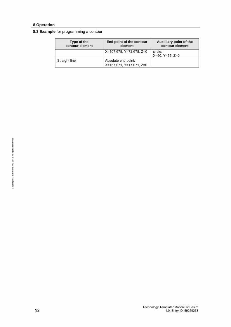
8 Operation
8.3 Example for programming a contour
92 Technology Template "MotionList Basic"
1.0, Entry ID: 59259273
Cop
yrig
ht
Sie
men
s A
G 2
012
All
right
s re
serv
ed
Type of the contour element
End point of the contour element
Auxilliary point of the contour element
X=107.678, Y=72.678, Z=0 circle: X=90, Y=55, Z=0
Straight line Absolute end point: X=157.071, Y=17.071, Z=0

8 Operation
8.3 Example for programming a contour
Technology Template "MotionList Basic" 1.0, Entry ID: 59259273 93
Cop
yrig
ht
Sie
men
s A
G 2
012
All
right
s re
serv
ed
Type of the contour element
End point of the contour element
Auxilliary point of the contour element
Circular arc Absolute end point: X=150, Y=0, Z=0
Absolute center point of the circle: X=150, Y=10, Z=0
Straight line Absolute end point: X=0, Y=0, Z=0
8.3.3 Creating the desired contour data block
The contour is to be stored in the contour data block DB 1001 in the technology CPU. For this purpose, open the HMI user interface and enter the desired data block number in the contour editor. Click the “Create” button afterwards.
Figure 8-12 Creating the contour data block DB 1001
The data block is created in the main memory of the technology CPU, assigned with the default values 0,000 and opened for processing.
8.3.4 Entering the contour elements
In the opened contour data block DB 1001 you can now define the individual contour elements or the motion commands via the drop-down list selection and the entry of the required parameters.

8 Operation
8.3 Example for programming a contour
94 Technology Template "MotionList Basic"
1.0, Entry ID: 59259273
Cop
yrig
ht
Sie
men
s A
G 2
012
All
right
s re
serv
ed
Figure 8-13 Entering the contour elements or the motion commands
The following values to be programmed for the sample contour ensue, whereby the entry of M and H functions was not included in this example. However, a configuration of these functions in the respective lines of the contour data block is easily possible.
Table 8-8 Entry values in the contour editor of the HMI use interface of the technology template
EndPoint AuxPoint Motion Command
X Y Z X Y Z
MoveLinearAbsolute 0,000 0,000 0,000 MoveLinearAbsolute 0,000 70,000 0,000 MoveCircularAbsolute_CE_S 10,000 80,000 0,000 10,000 70,000 0,000 MoveLinearAbsolute 30,000 80,000 0,000 MoveCircularAbsolute_CE_S 40,000 70,000 0,000 30,000 70,000 0,000 MoveLinearAbsolute 40,000 60,000 0,000 MoveCircularAbsolute_CE_S 50,000 50,000 0,000 50,000 60,000 0,000 MoveLinearAbsolute 60,000 50,000 0,000 MoveCircularAbsolute_CE_S 70,000 60,000 0,000 60,000 60,000 0,000 MoveLinearAbsolute 70,000 70,000 0,000
Page change (Button “>”) – Continue in contour editor on page 2 MoveCircularAbsolute_CE_S 80,000 80,000 0,000 80,000 70,000 0,000 MoveLinearAbsolute 90,000 80,000 0,000 MoveCircularAbsolute_CE_S 170,678 72,678 0,000 90,000 55,000 0,000 MoveLinearAbsolute 157,071 17,071 0,000

8 Operation
8.3 Example for programming a contour
Technology Template "MotionList Basic" 1.0, Entry ID: 59259273 95
Cop
yrig
ht
Sie
men
s A
G 2
012
All
right
s re
serv
ed
EndPoint AuxPoint Motion Command
X Y Z X Y Z
MoveCircularAbsolute_CE_S 150,000 0,000 0,000 150,000 10,000 0,000 MoveLinearAbsolute 0,000 0,000 0,000
The fully filled out contour data block DB 1001 is presented as follows:
Figure 8-14 Fully filled out contour data block DB 1001
Via the “Save” button the entries executed on the data block in the main memory of the technology CPU can now be transferred and can therefore be provided for processing the contour. After saving the executed changes, the contour data block is automatically closed in the contour editor.
8.3.5 Starting the processing of the contour entered
The processing of the contour saved in the DB 1001 contour data block can now be started and monitored via the “Contour Movement” operator screen of the HMI interface.
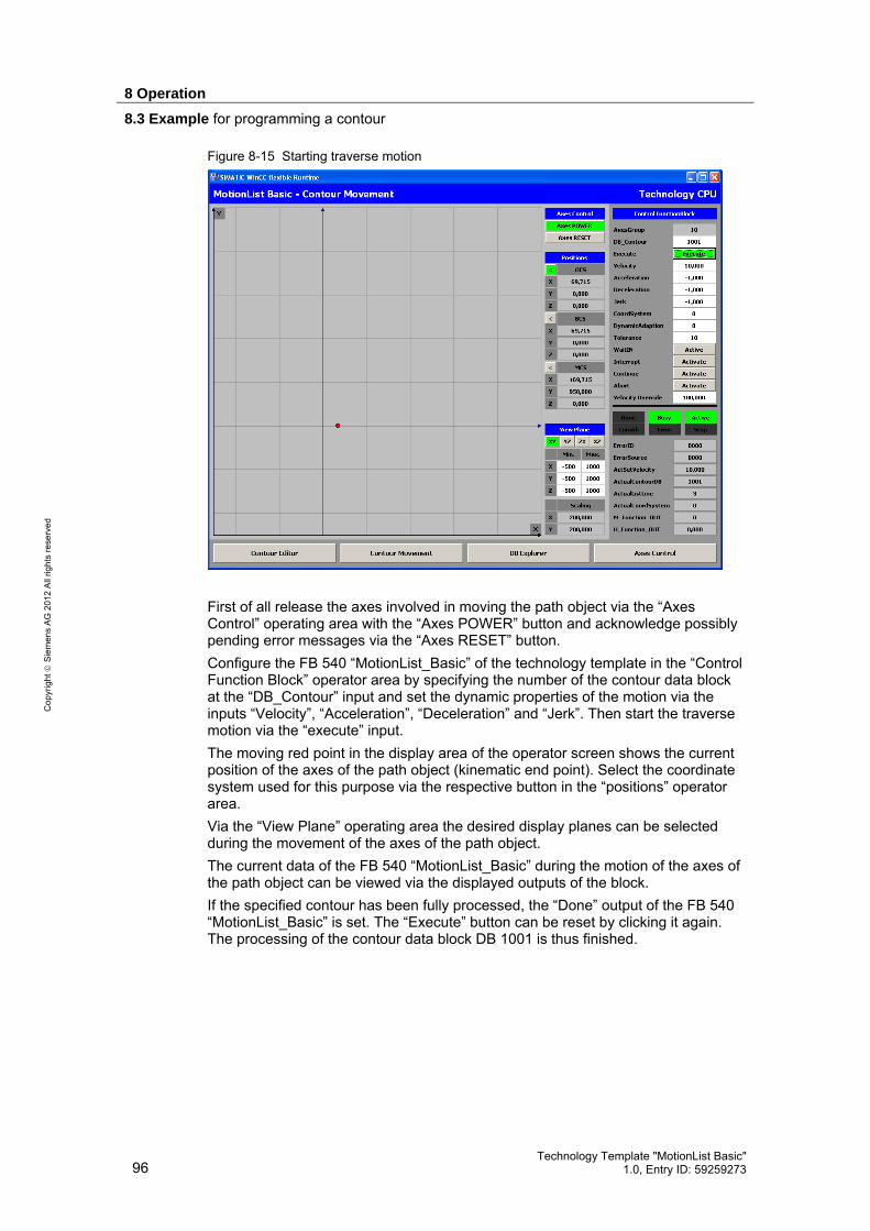
8 Operation
8.3 Example for programming a contour
96 Technology Template "MotionList Basic"
1.0, Entry ID: 59259273
Cop
yrig
ht
Sie
men
s A
G 2
012
All
right
s re
serv
ed
Figure 8-15 Starting traverse motion
First of all release the axes involved in moving the path object via the “Axes Control” operating area with the “Axes POWER” button and acknowledge possibly pending error messages via the “Axes RESET” button. Configure the FB 540 “MotionList_Basic” of the technology template in the “Control Function Block” operator area by specifying the number of the contour data block at the “DB_Contour” input and set the dynamic properties of the motion via the inputs “Velocity”, “Acceleration”, “Deceleration” and “Jerk”. Then start the traverse motion via the “execute” input. The moving red point in the display area of the operator screen shows the current position of the axes of the path object (kinematic end point). Select the coordinate system used for this purpose via the respective button in the “positions” operator area. Via the “View Plane” operating area the desired display planes can be selected during the movement of the axes of the path object. The current data of the FB 540 “MotionList_Basic” during the motion of the axes of the path object can be viewed via the displayed outputs of the block. If the specified contour has been fully processed, the “Done” output of the FB 540 “MotionList_Basic” is set. The “Execute” button can be reset by clicking it again. The processing of the contour data block DB 1001 is thus finished.

9 Program Description
9.1 Program structure
Technology Template "MotionList Basic" 1.0, Entry ID: 59259273 97
Cop
yrig
ht
Sie
men
s A
G 2
012
All
right
s re
serv
ed
9 Program Description
9.1 Program structure
The following chapters describe the program structure of the main block FB 540 “MotionList_Basic” of the “MotionList Basic” technology template in more detail. The other function blocks of the technology template are used for the management and manipulation of the contour data blocks and are mainly self-explanatory. This is why they are not dealt with in more detail in this chapter.
9.1.1 Basic program structure
The basics for the structure of the FB 540 „MotionList_Basic“ is the approach already explained in chapter 3.2.3 for the automated processing of nested technology functions for the interpolation: • Each technology function for the interpolation has to be available in two
instances in the block. • Whilst the axes are traversed via an instance of a technology function, the next
traverse job already has to be prepared in the second instance. • The processing of the specified contour is performed by mutual use of the two
instances of the technology function for the interpolation. • System commands to set diverse parameters can be executed without
changing an instance.
9.1.2 Steps of the state machine
Based on the principle program structure of the FB 540 “MotionList_Basic”, the following state machine is the result:
Figure 9-1 State machine of the “MotionList Basic"
Execute:True ð False
Execute:False ð True
Execute = False
Execute = True
NextLine&
MotionCommand
NextLine&
MotionCommand
NextLine&
No MotionCommandProgramEnd
ProgramEnd
NextLine&
No MotionCommand
Execute:False ð True

9 Program Description
9.1 Program structure
98 Technology Template "MotionList Basic"
1.0, Entry ID: 59259273
Cop
yrig
ht
Sie
men
s A
G 2
012
All
right
s re
serv
ed
In the individual states of the state machine, the following functions are executed:
Table 9-1 Function of the states of the state machine
State Function
0 NoOperation The technology template is active within the user program and is called; however, it does not execute a function.
1 Error An error has occurred while processing the technology template. This state can be jumped to from all existing states in the technology template. The error state can only be exited again by a restart of the technology templates via a rising edge on the “Execute” input.
2 Initialize Resetting of all used technology functions and variables in the technology template. Presetting of various internal variables with the default values stored in the function block. Adoption of the variables transferred to the interface of the technology template.
3 StopPathObject_S Transmitting a GroupStop job to the path object influenced via the technology template to create a defined state of the path object. The GroupStop job named here is also transmitted when the axes of the path object are controlled by the technology template and the “Execute” input of the FB 540 “MotionList_Basic” is reset.
4 StopPathObject_E Stopping the GroupStop job on the path object. In this state all axes of the path object influenced by technology template are now in standstill. If the technology template was finished via a falling edge on the “Execute” input of the FB 540 „MotionList_Basic” function block, it is branched off to the state 0 “NoOperation” from this state.
Start of the processing of the traverse contour 5 ReadProgram
(Instance 1) A line of the traverse program is read into the technology template from the contour data block.
6 StartMotion (Instance 1)
The line read in from the traverse program is interpreted within the technology template: • Depending on the command used, the respective
parameters from the read in line of the traverse program are passed on to the respective technology function or the respective variables are set within the technology template.
• The configured technology function is executed with a rising edge on the “Execute” input.
7 ReadProgram (Instance 2)
Another line of the traverse program is read into the technology template from the contour data block.

9 Program Description
9.1 Program structure
Technology Template "MotionList Basic" 1.0, Entry ID: 59259273 99
Cop
yrig
ht
Sie
men
s A
G 2
012
All
right
s re
serv
ed
State Function
8 StartMotion (Instance 2)
The line read in from the traverse program is interpreted within the technology template: • Depending on the command used, the respective
parameters from the read in line of the traverse program are passed on to the respective technology function or the respective variables are set within the technology template.
• The configured technology function is executed with a rising edge on the “Execute” input.
End of the processing of the traverse contour 9 EndProgram At the end of the motion contour, it is remained in this
state until all traverse jobs have been finished in the two instances of the technology functions.
10 Done The processing of the motion contour saved in the contour data block is finished.
9.1.3 Nested call of contour data blocks
In the “MotionList Basic” technology template it is possible to call another contour data block from a contour data block. With this, sub-program structures can be realized, when for example, always the same motion sequence is required for the machine axes in a production process. Such motion sequences can then each be stored in independent contour data blocks. The processing of traverse motions for a nested call of contour data blocks is generally performed in the same way, as if the entire contour was stored in a single contour data block. If the “CallContourDB” system command of the technology template is detected for the processing of a contour data block, the following program sequence will start within the technology template: 9. In the “DBList” structured list of the technology template the data block number
of the contour data block (“DBList.DBNumber”) currently in process is entered and the number of the currently active lines of the motion contour (“DBList.ActiveLine”).
7. Afterwards the nested call for the contour data block in the technology template is opened and the first line of this motion contour is read into the technology template.
If there is another “CallContourDB” system command in the nested call of the contour data block, the above procedure is repeated with each next line of the “DBList”. Due to the size of the structured “DBList” list, a maximum nesting depth for the contour data blocks of 10 is possible. If a nested call of a contour data block was fully processed, the respectively previous entry in the “DBList” in the technology template is read out and the previously interrupted contour data block is continued by the “CallContourDB” system command. This approach is continued until the first entry is reached again in the “DBList”.

9 Program Description
9.2 Data management
100 Technology Template "MotionList Basic"
1.0, Entry ID: 59259273
Cop
yrig
ht
Sie
men
s A
G 2
012
All
right
s re
serv
ed
9.2 Data management
The following chapters will explain the data management within the technology template in the various data and function blocks in detail.
9.2.1 Storage location of a motion contour
Each motion contour is fully saved in an independent data block that is structured as defined in the UDT 540 “ContourList”.
Figure 9-2 Storage location of a motion contour
A nesting of the individual data blocks is possible, i.e. it can be referred to another motion contour or another data block via a specified command from a motion contour or a data block.
9.2.2 Data flow when processing a motion contour
To process a motion contour the required contour data from FB 540 “MotionList_Basic” is read directly from the contour data block that contains the motion contour. This data is provided as parameter to the motion command or technology function block required for the execution of the traverse motion.
Figure 9-3 Data flow when processing a motion contour
Access to the data of the contour data block only takes place when the respective contour element has been processed, i.e. only when the required technology function is to be executed in the technology CPU.

9 Program Description
9.2 Data management
Technology Template "MotionList Basic" 1.0, Entry ID: 59259273 101
Cop
yrig
ht
Sie
men
s A
G 2
012
All
right
s re
serv
ed
ATTENTION A manipulation of the motion contour, i.e. the data in the contour data block is possible until the data is read in by the FB 540 “MotionList_Basic”.
However, this is not recommended!
Since the read-in time of the data by the FB 540 “MotionList_Basic” cannot be precisely predicted by the user, there could be inconsistencies if there are any data changes in the contour data block during the processing of the contour and therefore possibly undesired motions of the machine axes.
9.2.3 Data flow when manipulating a motion contour
To manipulate a motion contour, i.e. to enter and change the contour elements in a contour data block, an HMI user interface is provided that uses the FB 541 “HMI_List” in the technology CPU for the processing of the data in the contour data block. Two data areas are available in the FB 541 “HMI_List” for the processing of data of the contour data block: • DB_Data:
In this data area all data records of the contour data block are stored for processing when a motion contour is opened (open). After the processing, the manipulated data records are copied back (save) into the contour data block, as long as they are not to be aborted (abort).
• ContourList: This data area contains a section each of the “DB_Data” area and represents the contour elements that are currently displayed for processing in the HMI user interface. By changing the page (Next/Prev. Page) the data area can be filled with the respective new data from the “DB_Data” area.
Figure 9-4 Data flow when manipulating a motion contour

9 Program Description
9.2 Data management
102 Technology Template "MotionList Basic"
1.0, Entry ID: 59259273
Cop
yrig
ht
Sie
men
s A
G 2
012
All
right
s re
serv
ed
The manipulation of data of the contour data block in the FB 541 “HMI_List” via the HMI user interface is performed in two ways: • Direct processing of the displayed data:
If the parameters of the contour elements displayed in the HMI user interface are directly changed (and the entry is completed with ENTER) the data is first of all only stored in the "ContourList" area. Only if a page change (Next/Prev. Page) is performed or the block is closed (save), is the data written back into the “DB_Data” area and from there, if required, saved back into the contour data block.
• Administrative processing of the entire contour: This processing type means the inserting, deleting or copying of data (Insert/Delete/Copy) within an entire contour. This processing type is not restricted to the contour elements displayed in the HMI user interface. For the processing the possibly changed data in the “ContourList” has to be transferred in the “DB_Data” (Save) first of all. Now the administrative processing can be executed. Afterwards the “ContourList” area with the possibly changed data in the “DB_Data” may have to be refreshed so that the HMI user interface displays the correct data again.

10 Further Notes
Technology Template "MotionList Basic" 1.0, Entry ID: 59259273 103
Cop
yrig
ht
Sie
men
s A
G 2
012
All
right
s re
serv
ed
10 Further Notes
10.1 Position data for the contour definition
For the definition and programming of a motion contour in a contour data block you usually have several options to achieve the same axis movement. This chapters will support you in selecting the optimum programming method for your motion contour.
10.1.1 Relative and absolute position data
A contour element can usually be programmed with the help of relative or absolute position data. Both types offer advantages and disadvantages that will be explained in more detail below:
Table 10-1
Type Advantage Disadvantage
Relative programming
The contour element ends at a precisely defined distance to the current position of the machine axes. If you only have the length of the contour element as specification, this type of programming facilitates the creation of a program without additional calculations. This type of programming also offers advantages when motion processes are used more frequently. Thus, these motion processes can simply be executed in different positions in space.
No specification of precisely defined positions in the processing space, as a result of which possibly present position errors may be reproduced in the motion.
Absolute programming
The contour element ends at a precisely defined position in the processing space. This type of programming, for example, makes sense when approaching fixed pick-up and place-down positions in the processing space.
Slightly inflexible for the transmission of the motion process to another position in the processing space. If required, a complete the relocation of the coordinate system may have to be performed for the transmission of the motion process.
10.1.2 Circular constructions
If a circular arc is to be programmed with a specified radius between two points (start point and end point), there are several options to specify this circular arc. Principally, the following applies: The center point of the desired circular arc is respectively located on a circle with the specified radius around the start and the end point. The following cases can be distinguished: • If start point and end point are located further apart than double the radius,
then no circular arc can be constructed between these two points.

10 Further Notes
104 Technology Template "MotionList Basic"
1.0, Entry ID: 59259273
Cop
yrig
ht
Sie
men
s A
G 2
012
All
right
s re
serv
ed
• If start and end point are located precisely double the radius apart, then a semi circle between these two points is the result. The center point of the semi circle is precisely in the middle of the straight line between the two points.
• If start and end point are less then double the radius apart, then there are exactly two options for the location of the center point of the desired circular arc.
Figure 10-1 Circular construction via start point, end point and radius
Once the center point of the desired circle for connecting the two points has been specified, you now have to decide on the respective circular arc segment. On the two circles the motion from the start to the end point is each possible via two different circular arc segments: • Circular motion via the short segment:
For the programming of this motion the commands “MoveCircAbs_CE_S” or “MoveCircRel_CE_S” are available in the technology template.
• Circular motion via the long segment: For the programming of this motion the commands “MoveCircAbs_CE_L” or “MoveCircRel_CE_L” are available in the technology template.
Figure 10-2 Possible circular arc segments (short or long)

10 Further Notes
Technology Template "MotionList Basic" 1.0, Entry ID: 59259273 105
Cop
yrig
ht
Sie
men
s A
G 2
012
All
right
s re
serv
ed
10.2 Dynamic settings
10.2.1 Basics
For the consistent processing of a saved motion contour it is of great significance to have the dynamic settings for the axis movements selected correctly. Otherwise contour damages or deviations of the saved contour may very easily occur. The following settings influence the dynamic behavior of a path object for the processing of a saved motion contour: • Axis specific dynamic limits • Path-object specific dynamic limits • Dynamic specifications on the technology functions for the interpolation
10.2.2 Axis specific dynamic limits
The axis specific dynamic settings present the lowest level of the dynamic settings for the “MotionList Basic” technology template. Via the axis the kinematic of the machine is controlled. This is why they also have to be designed in a way so that the dynamic requirements to the axes and the kinematic can be fulfilled.
Figure 10-3 Axis specific settings – limits
The axis-specific dynamic limits themselves are also divided into two limit levels: • Limit on the hardware side:
These limit values provide the maximum permissible dynamic values of the mechanic of the machine. They therefore limit the loads on the drive section and on the kinematic of the machine.
• Limits set by the software side: These limit values provide the maximum dynamic values that can be specified by the user program for the axis. With regard to programming they therefore

10 Further Notes
106 Technology Template "MotionList Basic"
1.0, Entry ID: 59259273
Cop
yrig
ht
Sie
men
s A
G 2
012
All
right
s re
serv
ed
provide the limit of the dynamic values of the axis during the normal operation of the axis.
Note The axes of the path object or the machine have to have the highest dynamic within the machines in order to fulfill all dynamic requirements of the individual functions of the machine.
Presetting the dynamic values
Via presetting the axis, the default values for the dynamic settings of the axis can be set. These values within the user program are always used when the value “-1.0” is transferred for the dynamic settings on the respective technology function block.
Figure 10-4 Axis-specific settings – presettings
Set the values as high as possible in the presetting of the axis for the dynamic of the respective axis movement but always whilst taking the specified limits into account. The presetting of the axis should be selected in a way so that the axis offers the maximum permissible dynamic performance for continuous operation whilst using the default values.
Assistant for presetting the dynamic
To facilitate the determination of the required setting values, the “preset dynamic” dialog can be reached via the button with the same name in this setting mask. Here, various existing basic dynamic settings already available in the configuration software can be selected via a drop-down list:

10 Further Notes
Technology Template "MotionList Basic" 1.0, Entry ID: 59259273 107
Cop
yrig
ht
Sie
men
s A
G 2
012
All
right
s re
serv
ed
• Low dynamic • Medium dynamic • High dynamic • User-defined Via the three basic dynamic settings a first assignment of the dynamic values can be performed. If the default values for the maximum speed and the ramp-up time of the axis are changed, the basic setting changes to the “User-defined” mode.
Figure 10-5 Axis-specific settings – presetting dynamic
ATTENTION All changes performed in the “preset dynamic” dialog, are instantly accepted in the parameters of the respective axis.
The dialog is intended for the basic dynamic settings of an axis and should not be used again afterwards. Otherwise changes on the individual parameters may get lost again.
A precise description of the functionality of the dialog and the buttons contained therein can be found via the “Help” button or the online help of S7T Config.
10.2.3 Path-object specific dynamic limits
The limit values for the execution of the path motion via the “MotionList Basic” technology template are specified via the path-object specific dynamic limits. The limit values specified here are used for the generation of the path motion. However, it has to be ensured that the individual axes of the path object can maintain the dynamic data specified here. If the individual axes contain further
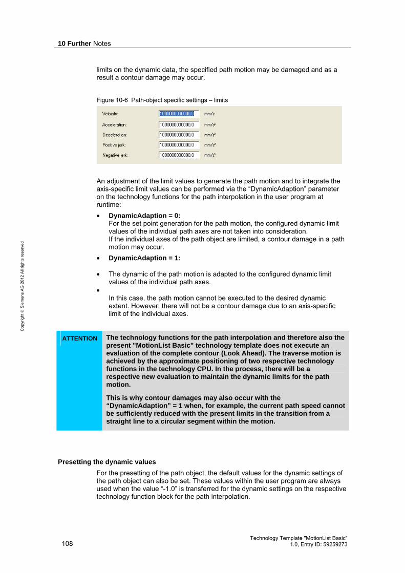
10 Further Notes
108 Technology Template "MotionList Basic"
1.0, Entry ID: 59259273
Cop
yrig
ht
Sie
men
s A
G 2
012
All
right
s re
serv
ed
limits on the dynamic data, the specified path motion may be damaged and as a result a contour damage may occur.
Figure 10-6 Path-object specific settings – limits
An adjustment of the limit values to generate the path motion and to integrate the axis-specific limit values can be performed via the “DynamicAdaption” parameter on the technology functions for the path interpolation in the user program at runtime: • DynamicAdaption = 0:
For the set point generation for the path motion, the configured dynamic limit values of the individual path axes are not taken into consideration. If the individual axes of the path object are limited, a contour damage in a path motion may occur.
• DynamicAdaption = 1:
• The dynamic of the path motion is adapted to the configured dynamic limit values of the individual path axes.
• In this case, the path motion cannot be executed to the desired dynamic extent. However, there will not be a contour damage due to an axis-specific limit of the individual axes.
ATTENTION The technology functions for the path interpolation and therefore also the present "MotionList Basic" technology template does not execute an evaluation of the complete contour (Look Ahead). The traverse motion is achieved by the approximate positioning of two respective technology functions in the technology CPU. In the process, there will be a respective new evaluation to maintain the dynamic limits for the path motion.
This is why contour damages may also occur with the “DynamicAdaption” = 1 when, for example, the current path speed cannot be sufficiently reduced with the present limits in the transition from a straight line to a circular segment within the motion.
Presetting the dynamic values
For the presetting of the path object, the default values for the dynamic settings of the path object can also be set. These values within the user program are always used when the value “-1.0” is transferred for the dynamic settings on the respective technology function block for the path interpolation.

10 Further Notes
Technology Template "MotionList Basic" 1.0, Entry ID: 59259273 109
Cop
yrig
ht
Sie
men
s A
G 2
012
All
right
s re
serv
ed
Figure 10-7 Path object-specific settings – presettings
10.2.4 Dynamic settings on the technology functions
The dynamic specifications for the path motion from the user program to the technology functions that are called in the technology template for the path interpolation, can be transferred via the FB 540 “MotionList_Basic“.
Figure 10-8 Technology template FB 540 “MotionList_Basic” – dynamic settings
If the parameters are assigned with the values “-1.0” here, the presettings from the path-object specific settings in S7T Config are used for the path motion.
10.2.5 Example for the dynamic setting based on a contour
The dynamic setting when using the technology template is to be illustrated once more based on the following sample contour and the points to be observed are presented in detail.
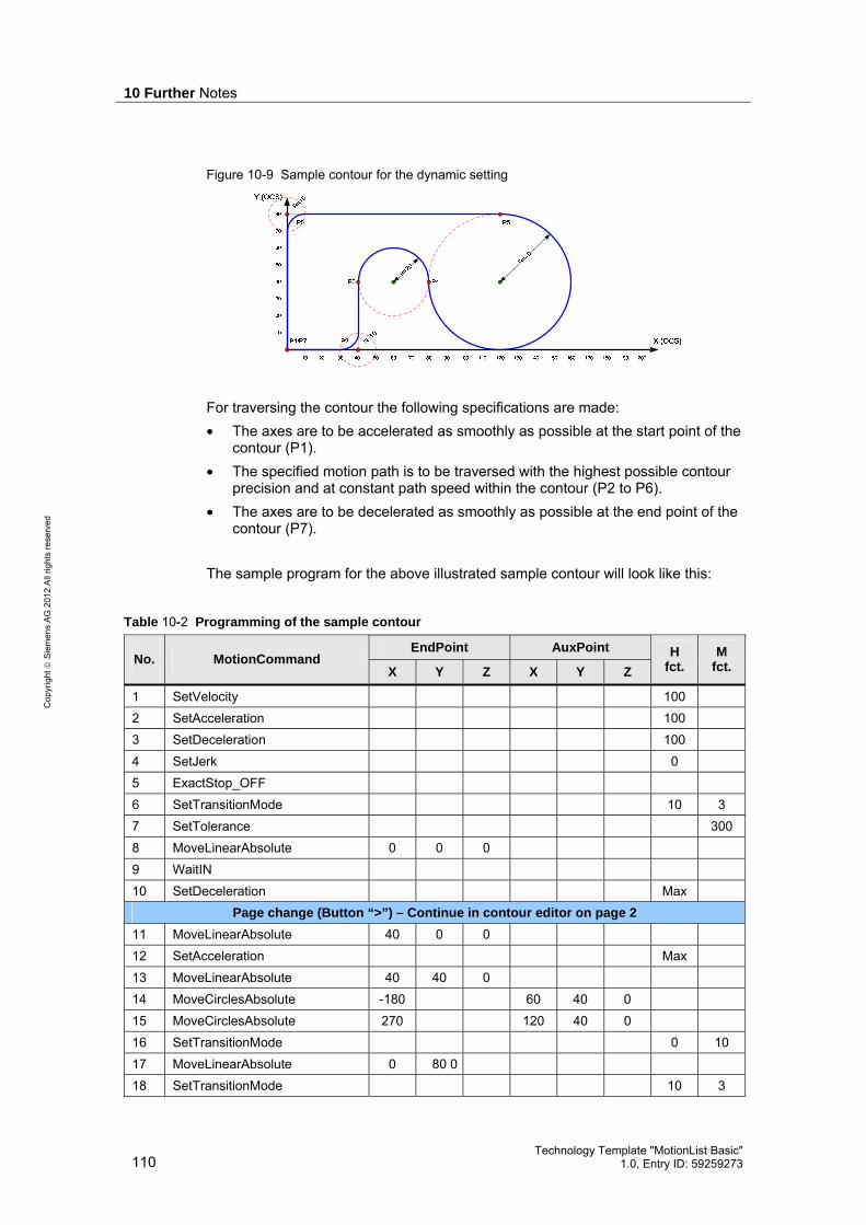
10 Further Notes
110 Technology Template "MotionList Basic"
1.0, Entry ID: 59259273
Cop
yrig
ht
Sie
men
s A
G 2
012
All
right
s re
serv
ed
Figure 10-9 Sample contour for the dynamic setting
For traversing the contour the following specifications are made: • The axes are to be accelerated as smoothly as possible at the start point of the
contour (P1). • The specified motion path is to be traversed with the highest possible contour
precision and at constant path speed within the contour (P2 to P6). • The axes are to be decelerated as smoothly as possible at the end point of the
contour (P7). The sample program for the above illustrated sample contour will look like this:
Table 10-2 Programming of the sample contour
EndPoint AuxPoint No. MotionCommand
X Y Z X Y Z
H fct.
M fct.
1 SetVelocity 100 2 SetAcceleration 100 3 SetDeceleration 100 4 SetJerk 0 5 ExactStop_OFF 6 SetTransitionMode 10 3 7 SetTolerance 300 8 MoveLinearAbsolute 0 0 0 9 WaitIN 10 SetDeceleration Max
Page change (Button “>”) – Continue in contour editor on page 2 11 MoveLinearAbsolute 40 0 0 12 SetAcceleration Max 13 MoveLinearAbsolute 40 40 0 14 MoveCirclesAbsolute -180 60 40 0 15 MoveCirclesAbsolute 270 120 40 0 16 SetTransitionMode 0 10 17 MoveLinearAbsolute 0 80 0 18 SetTransitionMode 10 3

10 Further Notes
Technology Template "MotionList Basic" 1.0, Entry ID: 59259273 111
Cop
yrig
ht
Sie
men
s A
G 2
012
All
right
s re
serv
ed
EndPoint AuxPoint No. MotionCommand
X Y Z X Y Z
H fct.
M fct.
19 SetDeceleration 100 20 MoveLinearAbsolute 0 0 0
The following specific program technology was observed for the programming of the sample program:
Table 10-3 Remarks for the programming of the sample contour
Line Comment
1 - 3 The dynamic of the path object for the start point of the contour is set at the beginning of the programming. The smooth approaching of the axes at the beginning of the contour is achieved by the dynamic settings made here. The basic dynamic settings can also be performed via the inputs “Velocity”, “Acceleration”, “Deceleration” and “Jerk” of the FB 540 “MotionList_Basic”.
4 By setting the jerk to value 0, the path object will use the trapezoidal acceleration profile without taking the jerk into account.
5 - 6 Selecting the approximate positing mode between the individual contour elements, i.e. the contour is traversed at constant path speed and the transitions between the contour elements are blended. For linear contour elements, the setting for the “TransitionMode” has to be taken into account too. Here, you set the transition to a straight line with a rounding radius (corner distance) of size 10 via “SetTransitionMode”.
7 The reliable deviation of the distances between start point and center point or end point and center point is set to value 0.3 (=300/1000).
8 – 9 The start point of the contour is approached and it is waited for the setting of the “WaitIN” input on FB 540 “MotionList_Basic”. The point (0/0/0) is only precisely approached if the “WaitIN” input is not set. If the input is already set or if “WaitIN” is not programmed in the contour table then the traversing of the contour is blended with the straight line, defined in line 11 with the help of a transition radius of size 10. The settings for this purpose have been made in line 6.
10, 12 The dynamic settings for the deceleration and acceleration are now set to the maximum values of the path object so that the contour elements can be traversed at the maximum contour accuracy achievable during the path motion. The acceleration is only set to the maximum value in line 12, so that approaching the contour in line 11 after the “WaitIN” in line 11 can still take place with the setting for smooth approaching.

10 Further Notes
112 Technology Template "MotionList Basic"
1.0, Entry ID: 59259273
Cop
yrig
ht
Sie
men
s A
G 2
012
All
right
s re
serv
ed
Line Comment
16 As soon as a tangential transition of a contour element is to take place in a straight line, i.e. without using a transition radius, the “TransitionMode” has to be set to value 10 (instantly). Otherwise there will be a drop of the path speed on the transition between the circular arc from line 15 and the straight line from line 17.
18 Now the transition radius between the straight line from line 17 and line 20 has to be switched back on.
19 For the smooth braking of the traverse motion on the contour, the deceleration has to be set to the according value again.
Note In order to achieve a higher contour precision, it may be advantages to approach the contour without jerk limit, i.e. to set the jerk to value 0. In this case the trapezoidal acceleration profile is used by the path object.
10.2.6 Points especially worth considering
When programming contour element transitions, some particularities are to be observed in view of the dynamic settings along the path motion that are to be explained in more detail here.
Tangential transitions between contour elements
If two contour elements knock into each other in a way so that the motion direction of the path motion does not have to be changed at the point of impact when traversing the contour, then this is called a tangential transition between the contour elements.
Figure 10-10 Example for tangential contour element transitions
Since no transition radius can be inserted between two contour elements at a tangential transition, the "TransitionMode" parameter always has to be set to value 10 (instantly). Otherwise there may be a drop of the path speed when traversing the contour.
Radius programming with the help of a transition radius
If two straight lines that form an angle of, for example, 90° at the point of impact, are traversed at a constant path speed, then a transition radius has to be inserted at the corner that forms at the angle. Otherwise the machine axes at this place

10 Further Notes
Technology Template "MotionList Basic" 1.0, Entry ID: 59259273 113
Cop
yrig
ht
Sie
men
s A
G 2
012
All
right
s re
serv
ed
have to be decelerated or accelerated at infinite acceleration, which is physically impossible. For the programming of a transition radius on the respective technology function, the “TransitionMode” parameter is available to select the transition mode and the “TransitionParameter” to define the radius for the transition radius.
Note Transition radii can only be defined between the following contour element transitions:
• Straight line – straight line • Circular arc – straight line
The definition of a transition radius between the following contour element transitions is not possible:
• Straight line – circular arc • Circular arc – circular arc
Reason: The parameters “TransitionMode” and “TransitionParameter” can only be defined on the technology function for a linear motion.
Therefore the programming of the two contour elements looks as follows: • Straight line from P1 to P2 • Straight line from P2 to P3 with TransitionMode=3 and TransitionParameter=10 Without transition radius (TransitionMode=10) the motion would take place on the first straight line from P1 to P2 and the axes would be decelerated until standstill on P2. Afterwards the second straight line would be executed from P2 to P3. If the transition radius is inserted (TransitionMode=3), the Y axis already has to start before the X axis has reached standstill. The transition radius is realized by the respective motion of the two axes.
Figure 10-11 Contour element transition straight line – straight line with transition radius
However, the path motion can only be executed at a uniform path speed when the dynamic of the two axes has been set in a way so that the deceleration of the axis from the specified path speed can be realized within the transition radius.
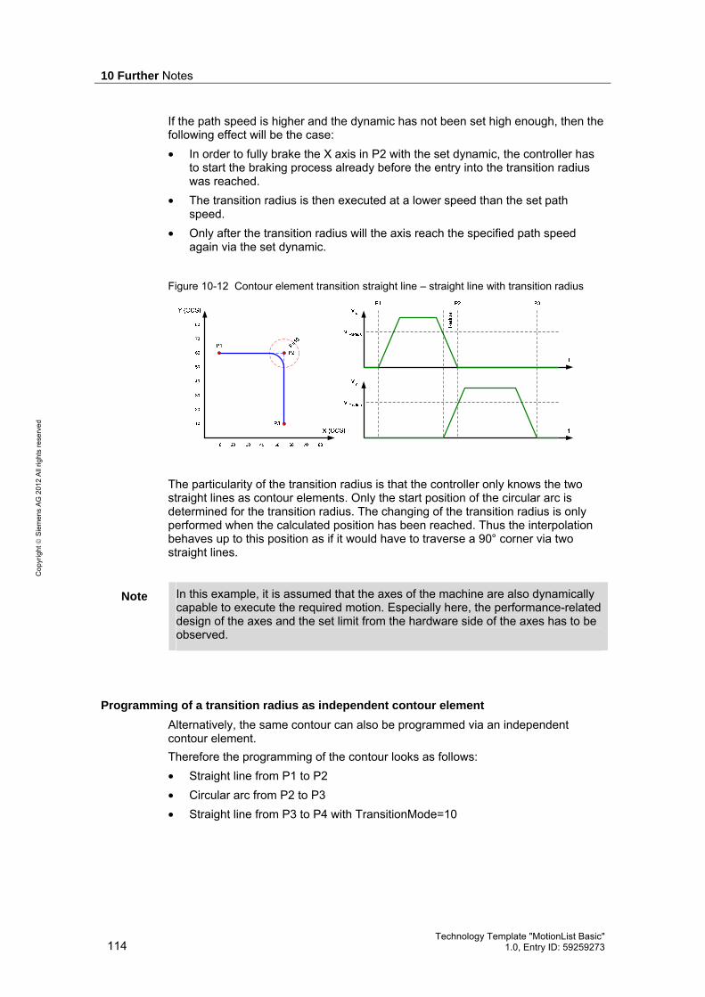
10 Further Notes
114 Technology Template "MotionList Basic"
1.0, Entry ID: 59259273
Cop
yrig
ht
Sie
men
s A
G 2
012
All
right
s re
serv
ed
If the path speed is higher and the dynamic has not been set high enough, then the following effect will be the case: • In order to fully brake the X axis in P2 with the set dynamic, the controller has
to start the braking process already before the entry into the transition radius was reached.
• The transition radius is then executed at a lower speed than the set path speed.
• Only after the transition radius will the axis reach the specified path speed again via the set dynamic.
Figure 10-12 Contour element transition straight line – straight line with transition radius
The particularity of the transition radius is that the controller only knows the two straight lines as contour elements. Only the start position of the circular arc is determined for the transition radius. The changing of the transition radius is only performed when the calculated position has been reached. Thus the interpolation behaves up to this position as if it would have to traverse a 90° corner via two straight lines.
Note In this example, it is assumed that the axes of the machine are also dynamically capable to execute the required motion. Especially here, the performance-related design of the axes and the set limit from the hardware side of the axes has to be observed.
Programming of a transition radius as independent contour element
Alternatively, the same contour can also be programmed via an independent contour element. Therefore the programming of the contour looks as follows: • Straight line from P1 to P2 • Circular arc from P2 to P3 • Straight line from P3 to P4 with TransitionMode=10
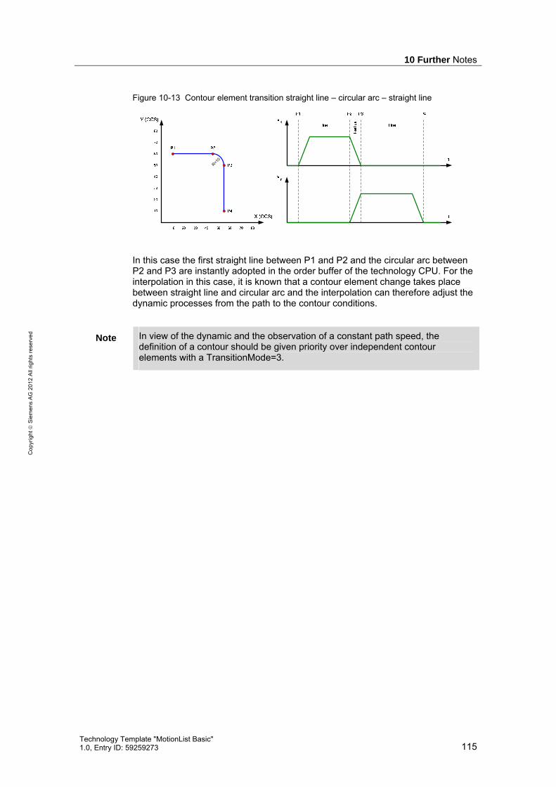
10 Further Notes
Technology Template "MotionList Basic" 1.0, Entry ID: 59259273 115
Cop
yrig
ht
Sie
men
s A
G 2
012
All
right
s re
serv
ed
Figure 10-13 Contour element transition straight line – circular arc – straight line
R=10
In this case the first straight line between P1 and P2 and the circular arc between P2 and P3 are instantly adopted in the order buffer of the technology CPU. For the interpolation in this case, it is known that a contour element change takes place between straight line and circular arc and the interpolation can therefore adjust the dynamic processes from the path to the contour conditions.
Note In view of the dynamic and the observation of a constant path speed, the definition of a contour should be given priority over independent contour elements with a TransitionMode=3.

11 Bibliographic References
116 Technology Template "MotionList Basic"
1.0, Entry ID: 59259273
Cop
yrig
ht
Sie
men
s A
G 2
012
All
right
s re
serv
ed
11 Bibliographic References
11.1 Bibliographic references
The following list is by no means complete and only provides a selection of appropriate sources.
Table 11-1 Bibliographic references
Topic Title
/1/ STEP 7 SIMATIC S7-300/400 Automating with STEP7 in STL and SCL Author: Hans Berger Publicis Publishing ISBN: 978-3895783418
/2/ STEP 7 SIMATIC Programming with STEP 7 V5.5 Manual Edition 05/2010 Document ID: A5E02789666-01 Order number: 6ES7810-4CA10-8BW0 http://support.automation.siemens.com/WW/view/en/45531107
/3/ STEP 7 SIMATIC – System and Standard Functions for S7-300/400 Volume 1 and Volume 2 Reference manual Edition 05/2010 Document ID: A5E02789976-01 Order number: 6ES7810-4CA10-8BW1 http://support.automation.siemens.com/WW/view/en/44240604
/4/ Technology CPU SIMATIC – S7-300 CPU 31xT Manual Edition 03/2008 Document ID: A5E01672599-02 http://support.automation.siemens.com/WW/view/en/21362915
/5/ Technology CPU SIMATIC Engineering Tools S7-Technology Function Manual Edition 10/2010 Document ID: A5E00251798-07 http://support.automation.siemens.com/WW/view/en/48353024
11.2 Internet Links
The following list is by no means complete and only provides a selection of appropriate sources.
Table 11-2 Internet links
Topic Title
\1\ Reference to this document
http://support.automation.siemens.com/WW/view/en/59259273
\2\ Siemens Industry http://support.automation.siemens.com

11 Bibliographic References
Technology Template "MotionList Basic" 1.0, Entry ID: 59259273 117
Cop
yrig
ht
Sie
men
s A
G 2
012
All
right
s re
serv
ed
Topic Title
Online Support

11 Bibliographic References
118 Technology Template "MotionList Basic"
1.0, Entry ID: 59259273
Cop
yrig
ht
Sie
men
s A
G 2
012
All
right
s re
serv
ed
Topic Title
\3\ Technology Template
Technology CPUs: Tech. Template "Move_Jog" http://support.automation.siemens.com/WW/view/en/21365191 Technology CPUs: Technology Template "flying shears" http://support.automation.siemens.com/WW/view/en/21062270 Technology CPUs: Technology Template "CrossCutter" http://support.automation.siemens.com/WW/view/en/31073433 Technology CPUs: Technology Template "Hydraulics Characteristic" http://support.automation.siemens.com/WW/view/en/27731588 Technology CPUs: Technology Template "Error Messages" http://support.automation.siemens.com/WW/view/en/21402122
\4\ Technology FAQ How can I display a cam disc of the technology CPU on the HMI using WinCC flexible? http://support.automation.siemens.com/WW/view/en/26680228 How can a simple palettizer be realized with a technology CPU and the FB 488 “MC_MovePath”? http://support.automation.siemens.com/WW/view/en/48206063 Which safety functions can you use with the interpolation on the fail-safe Technology CPU? http://support.automation.siemens.com/WW/view/en/48205978 How can you create a cam during runtime that is based on line segments (interpolation point table) and that connects these segments by continuous transitions? http://support.automation.siemens.com/WW/view/en/35690077 Which versions of the S7 Technology option package are available and which SINAMICS S120 drive firmware can you use with which of these versions? http://support.automation.siemens.com/WW/view/en/31051715 Which options exist for reading hardware limit switch signals into a technology CPU? http://support.automation.siemens.com/WW/view/en/25545745 Technology CPUs - How can you control a SINAMICS "Active Line Module" (ALM) via the PROFIBUS DP drive? http://support.automation.siemens.com/WW/view/en/25543996 Which encoders can you use with the Technology CPUs? http://support.automation.siemens.com/WW/view/en/25544321
\5\ Application & Tools
Technology CPUs: Parameterization of the “Gear Synchronization” Technology Function (SyncOp Guide) http://support.automation.siemens.com/WW/view/en/23577545 Technologie CPUs: Flying shears with print-mark synchronization based on gear synchronism http://support.automation.siemens.com/WW/view/en/21063352 Technologie-CPU 317TF-2 DP: Example for evaluation of the safety functions used in an application. http://support.automation.siemens.com/WW/view/en/47393794 Technology CPUs: "Kinematics Simulation Center" – Integration of simulation software to a technology CPU http://support.automation.siemens.com/WW/view/en/58260820

12 History
Technology Template "MotionList Basic" 1.0, Entry ID: 59259273 119
Cop
yrig
ht
Sie
men
s A
G 2
012
All
right
s re
serv
ed
12 History
Table 12-1 History
Version Date Modification
V1.0 04/2012 First issue


![Netex learningMaker | Basic Template v1.0 [Es]](https://img.dokumen.tips/doc/110x75/541608898d7f72336c8b4941/netex-learningmaker-basic-template-v10-es.jpg)