Embed Size (px)
Citation preview

PDF generated on 09 Oct 2017DISCLAIMER : UNCONTROLLED WHEN PRINTED – PLEASE CHECK THE STATUS OF THE DOCUMENT IN IDM
Technical Specification
Technical Summary for TCC0Global overview of the scope for TCC0 contract
Approval Process Name Action AffiliationAuthor Kotamaki M. 09 Oct 2017:signed IO/DG/COO/CST/TCSCo-Authors Rafin L.
Targa R. 06 Oct 2017:signed06 Oct 2017:signed
IO/DG/RCO/FPD/PCDIO/DG/COO/CST/TCS
ReviewersApprover Murphy S. IO/DG/COO/CST/TCS
Document Security: Internal UseRO: Kotamaki Miikka
Read Access LG: Contract/Finance for CMA, LG: TCC1 Tender Project Team , AD: IO_Director-General, AD: EMAB, AD: OBS - Tokamak Complex Section Division (TCS), AD: OBS - Construction Management Division (CMG), AD: Auditors, project administrator, RO
IDM UID
V89YJNVERSION CREATED ON / VERSION / STATUS
06 Oct 2017 / 2.0 / Signed
EXTERNAL REFERENCE / VERSION

PDF generated on 09 Oct 2017DISCLAIMER : UNCONTROLLED WHEN PRINTED – PLEASE CHECK THE STATUS OF THE DOCUMENT IN IDM
Change Log
Technical Summary for TCC0 (V89YJN)
Version Latest Status Issue Date Description of Change
v0.0 In Work 29 Sep 2017
v1.0 In Work 29 Sep 2017 First versionv1.1 Approved 29 Sep 2017 Solving layout/format issuesv2.0 Signed 06 Oct 2017 Alignment of the technical summary with the procurement summary of
TCC0 contract

Page 1 of 26
Table of Contents
1 PURPOSE............................................................................................................................22 ABBREVIATIONS .............................................................................................................23 GENERAL STATEMENT.................................................................................................3
3.1 STAGED APPROACH .......................................................................................................33.2 CONSTRUCTION AREAS .................................................................................................43.3 STRUCTURE ...................................................................................................................53.4 SCOPE OF ACTIVITIES.....................................................................................................53.5 STEPS IN BIDDING FOR THE CONTRACTS........................................................................73.6 CONTRACT SUPERVISION...............................................................................................7
4 INTERFACES AND RESOURCES..................................................................................84.1 BOUNDARY BETWEEN WORKSITE 1 AND WORKSITE 2...................................................84.2 WORKSHOPS..................................................................................................................84.3 INTERFACES TO OTHER CONTRACTS .............................................................................9
4.3.1 Interfaces to IO WS2 Contractors .........................................................................94.3.2 Scaffolding.............................................................................................................94.3.3 Lifting ....................................................................................................................9
5 REQUIRED COMPETENCES .......................................................................................10ANNEX I.1. WORKSITE 2 AND BUILDINGS RELEVANT FOR THE SCOPE OF THE TCC0 CONTRACT ..................................................................................................................12ANNEX I.2. SUMMARY OF QUANTITIES FOR TCC0 CONTRACT ............................13

Page 2 of 26
1 PurposeThe purpose of this document is to provide a high level definition of the scope of works and required Contractor competences for the Tokamak Complex Contract 0 (TCC0), covering the first part of the assembly works for the Tokamak Complex, also known as Worksite 2 of the ITER Project based in Saint Paul Lez Durance, France.
This document summarises the scope and strategy for the TCC0, details the essential expertise, experience and skills required of the TCC0 Contractor, hereinafter referred to “Contractor”, and provides a brief description of the works organisation
2 AbbreviationsThe following table lists and defines the abbreviations used in this document.
Abbreviation DefinitionASN Autorité de Sûreté NucléaireCCWS Component Cooling Water SystemCHWS Chilled Water SystemCMA Construction Management as AgentCWP Construction Work PackageDA Domestic AgencyE&IC Electrical, Instrumentation and ControlESPN Equipements Sous Pression Nucléaire (Nuclear Pressure Equipment)INB Installation Nucléaire de Base (Basic Nuclear Installation)IO ITER OrganizationIWP Installation Work PackageM&P Mechanical & PipingNDT Non Destructive TestingPIA Protection Important ActivitiesTAC Tokamak Assembly ContractTBM Test Blanket Modules SystemTCC Tokamak Complex ContractTCWS Tokamak Cooling Water SystemWS Worksite
Table 1 - Abbreviations and Acronyms
Page 3 of 26
3 General Statement
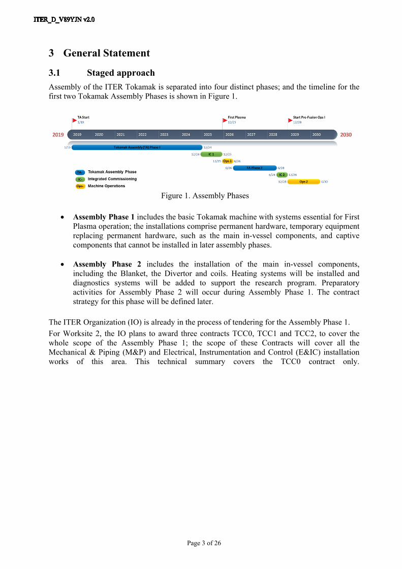
3.1 Staged approachAssembly of the ITER Tokamak is separated into four distinct phases; and the timeline for the first two Tokamak Assembly Phases is shown in Figure 1.
Figure 1. Assembly Phases
Assembly Phase 1 includes the basic Tokamak machine with systems essential for First Plasma operation; the installations comprise permanent hardware, temporary equipment replacing permanent hardware, such as the main in-vessel components, and captive components that cannot be installed in later assembly phases.
Assembly Phase 2 includes the installation of the main in-vessel components, including the Blanket, the Divertor and coils. Heating systems will be installed and diagnostics systems will be added to support the research program. Preparatory activities for Assembly Phase 2 will occur during Assembly Phase 1. The contract strategy for this phase will be defined later.
The ITER Organization (IO) is already in the process of tendering for the Assembly Phase 1. For Worksite 2, the IO plans to award three contracts TCC0, TCC1 and TCC2, to cover the whole scope of the Assembly Phase 1; the scope of these Contracts will cover all the Mechanical & Piping (M&P) and Electrical, Instrumentation and Control (E&IC) installation works of this area. This technical summary covers the TCC0 contract only.

Page 4 of 26
3.2 Construction AreasThe works in the scope of the Contract are located on the ITER Platform currently under construction in Cadarache, Southern France. Central to the facility is the Tokamak Complex, a nuclear rated structure in reinforced concrete that comprises three integrated buildings, Figure 2. The Complex has a footprint of 118 x 81 m, extends vertically from -15 m to +40 m relative to ground level, and contains the plant systems that service (power, heat, cool, condition, fuel, monitor and control) the Tokamak machine.,:
Figure 2. Site Overview – Future Final Configuration
The ITER site has been divided into 5 independent main worksites (WS). The worksites are defined to collect together groups of buildings and areas by major discipline, in order to better allocate works Contractors and suitably qualified persons. As presented in the Figure 3 below, the breakdown of the site and works is the following:
WS1 - Tokamak Basic Machine (including Assembly and Cleaning Facility buildings)WS2 - Tokamak Complex buildings (excluding Tokamak Pit)WS3 - Other nuclear buildings and Control buildingWS4 - Cryogenic plant and Site Services buildingsWS5 - Electrical Areas and Power Supplies Buildings
RF Heating Building B15
Page 5 of 26
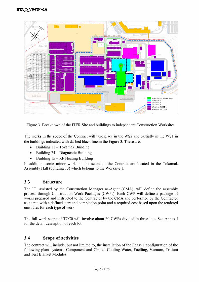
Figure 3. Breakdown of the ITER Site and buildings to independent Construction Worksites.
The works in the scope of the Contract will take place in the WS2 and partially in the WS1 in the buildings indicated with dashed black line in the Figure 3. These are:
Building 11 – Tokamak Building Building 74 – Diagnostic Building Building 15 – RF Heating Building
In addition, some minor works in the scope of the Contract are located in the Tokamak Assembly Hall (building 13) which belongs to the Worksite 1.
3.3 StructureThe IO, assisted by the Construction Manager as-Agent (CMA), will define the assembly process through Construction Work Packages (CWPs). Each CWP will define a package of works prepared and instructed to the Contractor by the CMA and performed by the Contractor as a unit, with a defined start and completion point and a required cost based upon the tendered unit rates for each type of work.
The full work scope of TCC0 will involve about 60 CWPs divided in three lots. See Annex I for the detail description of each lot.
3.4 Scope of activitiesThe contract will include, but not limited to, the installation of the Phase 1 configuration of the following plant systems: Component and Chilled Cooling Water, Fuelling, Vacuum, Tritium and Test Blanket Modules.
Page 6 of 26
The scope of this contract includes various activities such as:
Construction execution documentation to properly perform the construction works,
All the necessary documentation required to undertake and to follow-up installation activities and to record and trace all activities (as built dossier),
Pre-manufacturing and Installation of pipe spools including related supports and insulation,
Installation of pre-manufactured pipe spools and other related items procured by ITER Domestic Agencies (DA),
Installation of specific systems requiring special cleanliness, techniques or accuracy (e.g. fuelling lines, vacuum lines),
Pre-manufacturing and Installation of pipe spools including related supports according to the ESPN regulation,
Installation Tests (e.g. NDT, pressure test, leak tests and vacuum tests),
Preservation works,
Finishing works (e.g. internal cleaning, touch-up paint, thermal insulation, cladding, labelling and tagging),
The Contractor shall also be responsible for the following items: Provide any required temporary works including, but not only, the means of protection
and the tools needed to properly manage and perform the different stages of work in the buildings and on site,
The Contractor will be responsible for defining the scaffolding needs. The IO will provide the needed scaffolding through a service contractor while the CMA will coordinate the services.
Minor lifting and handling equipment required for the installation of the described items in Annex I.
Issue all necessary documentation for the works such as, but not limited to, Quality Plan, Health and Safety plan, workforce planning (Installation sequence and Level 4 Schedule) and the List of documents to be issued for the execution of the works.
Provide the records of NDT’s and all the information required to comply with regulation and applicable codes,
Perform final installation tests (mechanical completion) and verifications at the mechanical completion of the Structural, Mechanical & Piping including:
- Verification that the piping systems, mechanical equipment and their supporting structure are correctly installed
- Non-destructive examination- Hydrostatic tests- Technical cleaning (foreign material exclusion, dust control, flushing or others)
The required areas of expertise for the above activities are defined in Section 5 and Annex I.

Page 7 of 26
For some horizontal activities (e.g. handling, lifting, scaffolding, transport) the Contractor shall have to interface with the companies awarded for these specific activities. The interfaces will be managed by the CMA under the surveillance of the IO.
As well as planned CWPs the IO may define additional work packages to implement modifications to components, tools or processes, or to implement corrective actions. These will be agreed with the contractors in advance.
4 Interfaces and Resources
4.1 Boundary between Worksite 1 and Worksite 2As described in section 3.2 and in figure 3 the works in the scope of the Contract take place in Worksite 2 (WS2) which includes Tokamak building 11. The physical boundary of the Tokamak Machine inside building 11 is, for the purpose of assembly and installation works, defined by the outer surface of the bio-shield, indicated with red circle in figure 4. In general terms, this surface demarcates the Tokamak machine assembly works to be executed by the TAC Contractors (WS1) from the Tokamak Complex plant installation works to be executed by the TCC Contractors and others (WS2).
Figure 4. Physical boundary principle between WS1 and WS2 in the Building 11
WS1 - PIT
WS2 – BUILDING 11
WS2 – BUILDING 11

Page 8 of 26
4.2 WorkshopsThe IO will provide an area dedicated to the Contractor for the installation of his site facilities, possibly covering a workshop, local storage, and some pre-assembly activities on smaller components. These areas will be located on the ITER Worksite platform. The areas will be connected to the potable water, IT and electrical networks as well as to the industrial drainage network.
To support the pre assembly activities, the Contractor shall provide a general workshop facility within the area described above and as appropriate to volume and schedule an off-site locally workshop to enable the pre fabrication and modification of pipe spools, steel structure, supports, insulation, temporary meanings, etc. These workshops shall be staffed by competent technicians, and have an acceptable selection of hand tools, machine tools, control instrumentation and welding equipment. Part of these workshops shall be segregated for carbon and stainless steel fabrication.
The contractor will be fully responsible for transport between the ITER site and these workshops, and for any ITER components while off-site.
On the site, ITER has available a number of buildings for component storage. In general IO tools and components will be collected by the Contractor from these storage locations, and returned to them on completion of the corresponding CWP.
4.3 Interfaces to Other Contracts
4.3.1 Interfaces to IO WS2 ContractorsThe Contractor may:
Execute a CWP where the preceding CWP was performed by another contractor; Complete a CWP where the following CWP is performed by another contractor;
At the start of a CWP the Contractor will have an opportunity to examine and accept the components/environmental conditions, and at the end of the works, the completion will be certified by the IO with the support of the CMA.
4.3.2 ScaffoldingThe IO will put in place a framework contract for the lease of scaffolding (scaffolding contractor). This contract will be for the provision of scaffolding to the Contractor and other IO works contractors.Due to the high level of interaction between different contractors, the use of this scaffolding contract will be obligatory for all work being carried out in WS2 as several works contractors may use the same scaffolding. IO will pay the scaffolding contractor directly.
4.3.3 LiftingIn order to avoid that each Works Contractor places a separate subcontract for the hire of lifting equipment (mainly mobile cranes), IO had envisaged the obligatory use of a single contractor throughout the ITER Site (excluded Contractors areas and workshops).

Page 9 of 26
The use of this framework contract shall be obligatory for the IO Contractors working in WS2. The IO will pay the lifting contractor directly but the responsibility for the lifting operation shall remain with the Contractor.
5 Required Competences The competence and experience of the Contractor, and the ability, experience, and training of his engineering and construction team will have a direct influence on quality, re-work, and schedule, and ultimately on the performance of the Tokamak during operation; the Contractor will be required to demonstrate competence and experience in a number of key areas as listed in Table 2.
Area of CompetenceCodes and StandardsOccupational SafetyProcess Development and QualificationQuality Assurance / Quality ControlRegulated constructionProcess piping and equipment installationNuclear Pressure Equipment regulationVacuum pipes installationMulti core pipes installationCarbon and stainless steel welding processInspection and Non-Destructive ExaminationInstrumentation InstallationLifting and HandlingTooling Maintenance, Storage and Preservation
Table 2. Required Competences

Page 10 of 26
ANNEX I
Tokamak Complex Installation WorksTCC0 Contract
Overview of Scope of Work

Page 11 of 26
Annex I.1. Worksite 2 and buildings relevant for the scope of the TCC0 Contract
Figure A1. Buildings relevant for the scope of the Contract.
Assembly Building 13
Tokamak Building 11
Tritium Building 14
RF Heating Building 15
Diagnostic Building 74
Tokamak Complex

Page 12 of 26
Annex I.2. Summary of Quantities for TCC0 Contract
Table A1. Summary of Quantities
Cooling Water System
Building Item Qty Unit Material Max. Size Lot Remarks
Pipe 5000 m 304L DN300 Lot 1&3
Valve 750 each 304L Lot 1&3
B11 (Levels B2/B1/L1/L2)
Support 35 Ton CS Lot 1&3
Pipe 500 m 304L DN500 Lot 2 Include 60pcs prefabricated spools
Valve 100 each 304L Lot 2 B13
Support 3 Ton CS Lot 2
Pipe 1000 m 304L DN700 Lot 2 Include 200pcs prefabricated spools
Valve 250 each 304L Lot 2 B15
Support 25 Ton CS Lot 2 Pipe 1300 m 304L DN300 Lot 2
Valve 350 each 304L Lot 2 B74 (Levels B2/B1/L1/L2) Support 10 Ton CS Lot 2
Gas Distribution System (GDS) Manifold – Multicore Gas Line
Building Item Qty Unit Material Max. Size Lot Remarks
B11(Levels B1/L2) spool 40ca. each
316 L (Process pipes &
Outer jacket)
DN 250 (Outer jacket)
Lot 3
Tritium System pipes
Building Item Qty Unit Material Max. Size Lot Remarks
B11 (Levels B2/B1/L1/L2)
Pipe 1800 m Stainless steel DN300 Lot 1
Vacuum System pipes
Building Item Qty Unit Material Max. Size Lot Remarks
B11 (Levels B1/L1) Pipe 2200 m Stainless steel DN300 Lot 3
TBM pipes
Building Item Qty Unit Material Max. Size Lot Remarks
B11 (Levels L1/L2) Pipe 850 m Stainless steel DN60 Lot 3

Page 13 of 26

Page 14 of 26

Page 15 of 26

Page 16 of 26

Page 17 of 26

Page 18 of 26

Page 19 of 26

Page 20 of 26

Page 21 of 26

Page 22 of 26
Page 23 of 26

Page 24 of 26

Page 25 of 26

Page 26 of 26