Embed Size (px)
Citation preview

Technical Readiness of Ocean Thermal Energy Conversion (OTEC)
November 3 – 5, 2009
National Oceanic and Atmospheric Administration
National Ocean Service Office of Ocean and Coastal Resource Management
Coastal Response Research Center University of New Hampshire
1
FOREWORD
The Coastal Response Research Center, a partnership between the National Oceanic and Atmospheric Administration (NOAA) Office of Response and Restoration (ORR) and the University of New Hampshire (UNH), develops new approaches to marine environmental response and restoration through research and synthesis of information. In 2009, the center partnered with NOAA’s Office of Ocean and Coastal Resource Management (OCRM) to host a series of workshops to gather information about Ocean Thermal Energy Conversion (OTEC). The Ocean Thermal Energy Conversion Act of 1980 (OTECA) designates NOAA as the lead licensing agency for OTEC projects. All federal authorizations, with the exception of those of the U.S. Coast Guard, are to be issued under the NOAA license and within the procedural timeframes of OTECA. As the primary licensing agency, NOAA OCRM sponsored these workshops, developed the agenda and workshop goals, and were integral in the synthesis of information obtained from the workshop.
The first workshop, held in November, 2009 at the University of New Hampshire
in Durham, NH, aimed to assess the technical readiness of key components of OTEC technology. This report provides a qualitative analysis of the technical readiness of seven key components of OTEC technology: cold water pipe, platform/pipe interface, heat exchangers, platform, pumps and turbines, power cable, and platform mooring. The report is designed to serve as a resource for NOAA OCRM and governmental decision makers, as well as the OTEC community to summarize the current state of technical readiness and identify key research needs.
I hope you find the report interesting and exploring the discussion insightful. If you have any comments, please contact me. I look forward to hearing from you.
Sincerely,
Nancy E. Kinner, Ph.D.
UNH Co-Director, Coastal Response Research Center Professor of Civil/Environmental Engineering

2
Acknowledgements
The Coastal Response Research Center gratefully acknowledges the CRRC authors of this report: Joseph J. Cunningham, Zachary E. Magdol, and Nancy E. Kinner. The Center acknowledges the time and effort provided by the participants in the workshop, whose contributions have been synthesized into this report. In addition, the Center acknowledges the thoughtful input and comments received from the reviewers of the draft report: Whitney Blanchard (NOAA), Kerry Kehoe (NOAA), Peter Pandolfini (John Hopkins University), and Avram Bar-Cohen (University of Maryland). The following individuals helped plan this workshop: Roger Bagbey (Inspired Systems); Hoyt Battey (US DOE); Whitney Blanchard (NOAA-OCRM); Brian Cable (NAVFAC); Kerry Kehoe (NOAA-OCRM); Andrew Knox (NAVFAC); Dallas Meggitt (Sound and Sea Technology); Mike Reed (US DOE); Susan Skemp (FAU Center for Ocean Energy Technology); William Tayler (NAVFAC); and Iris Ioffreda (OLA Consulting). The Center staff for this meeting consisted of: Nancy Kinner, Kathy Mandsager, Joseph Cunningham, Zachary Magdol, Michael Curry, Chris Wood, Nate Little, Adria Fichter, Marcel Kozlowski, Heather Ballestero, and Michaela Bogosh. The Center also gratefully acknowledges Roger Bagbey, Whitney Blanchard, Rick Driscoll, Matt Gove, Dallas Meggitt, Mike Reed, and Andy Knox for serving as group leaders. Cover images courtesy Natural Renewable Energy Lab (NREL) and Joseph Cunningham. Citation: Coastal Response Research Center. 2010. Technical Readiness of Ocean Thermal Energy Conversion (OTEC). University of New Hampshire, Durham, NH, 27 pp and appendices.

3
Table of Contents
Foreword……………………………… ……………………..…..……………………... 1 Acknowledgements……………………………………………….….……………......... 2 I. Executive Summary………………………………………...…………………... 4
II. Introduction……………………………………………..…………………….... 5
III. Workshop History and Limitations…………………….………………………. 7
IV. Workshop Organization and Structure……………..….……………………….. 8
V. Breakout Group Reports……………………………….……………………..… 9
A. Platforms..…….………………..……………………….………………. 9
B. Platform Mooring…………………………………………….……….. 10
C. Platform/Pipe Interface........................................................................... 12
D. Heat Exchangers..................................................................................... 15
E. Pumps and Turbines……………….…………………….….………… 18
F. Power Cable……………………….…………………….……….……. 20
G. Cold water Pipe…………………….………………………..………… 22
VI. Research and Development Needs…………………………….………………. 24
VII. Conclusions……………………………………………………………………. 25
VIII. References Cited……………………………………………………..………... 26
Appendices: A. Workshop Agenda B. Participant List C. Breakout Questions D. Breakout Groups E. Breakout Group Notes and Report Outs F. Powerpoint Presentations

4
I. EXECUTIVE SUMMARY
Ocean Thermal Energy Conversion (OTEC) is a technology that dates back to the late 1800’s and makes use of temperature differences between surface and deep ocean waters to drive a heat engine, and extract energy via the Rankine cycle. While pilot scale plants (< 1 MWe) have successfully generated energy, a combination of technical and economic feasibility limitations tempered investment and interest in OTEC. However, the decreasing supply, and increasing costs, of fossil fuels, advancements in OTEC technology, renewable energy mandates, and energy security concerns have resulted in a resurgence in interest in OTEC for tropical locations.
As the lead licensing agency for OTEC, NOAA’s Office of Ocean and Coastal
Resource Management (OCRM), in cooperation with the Coastal Response Research Center (CRRC), held the first in a series of workshops to determine the technical readiness of seven major components of OTEC: 1) cold water pipe; (2) heat exchangers; (3) platform/pipe interface; (4) platform; (5) power cable; (6) platform mooring system; and (7) pumps and turbines. The first workshop, discussed in this report, sought to gather information on the technical readiness of OTEC and evaluate advancements to the technology since the last major attempt, OTEC-1 in 1980.
The qualitative analysis of the technical readiness of OTEC by experts at this
workshop suggest that a < 10 MWe floating, closed-cycle OTEC facility is technically feasible using current design, manufacturing, deployment techniques and materials. The technical readiness and scalability to a > 100 MWe facility is less clear. Workshop participants concluded that existing platform, platform mooring, pumps and turbines, and heat exchanger technologies are generally scalable using modular designs (several smaller units to achieve the total capacity needed), however, the power cable, cold water pipe and the platform/pipe interface present fabrication and deployment challenges for ≥ 100 MWe facilities, and further research, modeling and testing is required. The experience gained during the construction, deployment and operation of a ≤ 10 MWe facility will greatly aid the understanding of the challenges associated with a ≥ 100 MWe facility, and is a necessary step in the commercialization and development of OTEC.

5
II. INTRODUCTION
The decreasing supply, and increasing cost, of fossil-fuel based energy has intensified the search for renewable alternatives. Although traditionally more expensive, renewable energy sources have many incentives, including increased national energy security, decreased carbon emissions, and compliance with renewable energy mandates and air quality regulations. In remote islands where increased shipping costs and economies of scale result in some of the most expensive fossil-fuel based energy in the world, renewable energy sources are particularly attractive. Many islands, including Guam and Hawaii, contain strategic military bases with high energy demands that would greatly benefit from an inexpensive, reliable source of energy independent of the fossil-fuel based economy.
The oceans are natural collectors of solar energy and absorb billions of watts of
energy from the sun in the form of solar radiation daily. In the tropical latitudes, intense sunlight and longer days result in significant heating of the upper 35 to 100 m of the oceans, yielding comparatively warm (27 - 29°C) oceanic surface waters. Below this warm layer the temperature gradually decreases to an average of about 4.4°C. When the second law of thermodynamics is considered, this temperature differential represents a significant amount of potential energy which, if extracted, would be a completely renewable source of energy.
One method of extracting this energy is Ocean Thermal Energy Conversion
(OTEC). OTEC facilities take advantage of the Rankine cycle, a process which converts thermal energy into kinetic energy via turbines. The turbines can then be used to drive generators, producing electricity. There are two major OTEC facility designs: open-cycle, and closed-cycle. In an open-cycle OTEC facility seawater is used as a working fluid. Warm surface water is exposed to a vacuum, causing it to boil and generate steam. The cold water from deep in the ocean is then pumped through a condenser, causing the steam to condense (Figure 1). This constant vaporization and condensation is used to drive a turbine, converting thermal energy into mechanical energy. The open-cycle process has the added advantage of creating fresh water as a byproduct.
Figure 1: Principles of operation of an open-cycle OTEC Facility

6
In a closed-cycle facility, a working fluid with a low boiling point (i.e., ammonia) is used in place of seawater. Both the warm and cold water are passed through heat exchangers which transfer the heat to the working fluid, which then vaporizes and condenses as in the open-cycle facility, driving a turbine and converting thermal energy into mechanical energy (Figure 2). While closed-cycle facilities are more complex, they are significantly more efficient and result in greater output due to the greater efficiency of the working fluid.
Figure 2: Principles of operation of a closed-cycle OTEC facility Development of OTEC dates back to the late 1800s, however the first attempt at
constructing an operational OTEC facility did not occur until 1930 off the coast of Cuba, and produced a net 22 kilowatts (kWe)1 for 11 days before it was destroyed in a storm. The next major milestone came in 1979 when a project dubbed “mini-OTEC” was launched, and marked the first successful operation of a closed-cycled OTEC facility. Mini-OTEC produced a net 15 kWe for 3 months before the planned shutdown, and was widely considered a success. The next major advancement in OTEC came in 1980 – 1981 with the experimental OTEC-1 facility. This facility was not designed to generate electricity, rather, it was designed as a platform to test various OTEC-related technologies. OTEC-1 reached several milestones, including successful deployment of a 670 m long cold water pipe, and mooring in 1,370 m of water. Subsequently, numerous small-scale (< 1 megawatts (MWe)2) experimental facilities have been constructed by Japan and India, and a land-based OTEC facility on the island of Hawai’i, with mixed success. The land-based facility on the island of Hawai’i successfully operated from 1993 to 1998, and produced a net 103 kW, and still holds the world record for OTEC output (Vega L. A., 2002/2003).
One of the most important considerations when planning an OTEC facility is
location. Large differences (> 20°C) in temperature between the cold water intake and the warm water intake are required, and as a result, the facility must be located in a region with access to warm surface waters and deep, cold water. An OTEC facility can be
1 kWe = 1,000 joules of electrical energy produced per second 2 MWe = 1,000,000 joules of electrical energy produced per second

7
located on land if adjacent to a shelf or rapid decrease in depth, however, the long length of the cold water intake pipe needed to reach the required temperature differential may make this impractical in most locations. Alternatively, an offshore, floating, moored, facility with a vertical cold water intake pipe may be more practical. Technological advancements in the offshore oil industry have made floating OTEC platforms a possibility. Floating platforms can be located virtually anywhere above deep water as long as they can be adequately moored, and the power cable can reach a land-based power grid for electricity generation.
Although the focus of OTEC is typically on production of electricity, the energy
produced has the potential to be used for numerous co-products, including desalinization, mariculture, hydrogen production, and air-conditioning, all of which would add to its economic viability and further reduce dependence on fossil fuels.
OTEC facilities are complex and house many components working together to
produce energy. The quantity and magnitude of these components will vary with the size of the facility, however, will typically consist of: a platform, used as a base for all OTEC operations; a cold water pipe, used to draw cold water from below the thermocline; a warm water pipe, used to draw warm water from near the surface; warm and cold water discharge pipes, which are used to return the cold and warm water after heat has been extracted; working fluid, used as a heat transfer medium; heat exchangers (closed-cycle only), evaporators and condensers, used to transfer heat between cold and warm waters and the working fluid; a platform/pipe interface, which couples the cold and warm water pipes and platform; a power cable, which transfers electricity back to a shore-based electrical grid; a platform mooring system, which ensures that the OTEC facility remains stable and in the same location; pumps, which draw water through the cold and warm water pipes; and turbines and generators, which are used to convert thermal energy into electricity.
Expectations for OTEC were high following the passage of the Ocean Thermal
Energy Conversion Act of 1980 (OTECA), and OTEC was forecast to generate > 10,000 MWe of energy by 1999. A combination of economic and technical feasibility factors brought development of the technology to a near standstill by the mid-1980s, and the technology has never proceeded past the pilot plant stage. Recently, decreasing availability and increased cost of fossil fuels, advancements in OTEC technology, and interest in renewable alternatives have once again led to a resurgence in interest in OTEC as a potential solution to the energy needs of many island and equatorial nations.
III. WORKSHOP HISTORY AND LIMITATIONS
Due, in part, to increased interest by the U.S. Navy and the issuance of several recent contracts to industry to increase research and development on OTEC components, NOAA’s Office of Ocean and Coastal Resource Management (OCRM), in cooperation with the Coastal Response Research Center (CRRC), held the first in a series of workshops focused on OTEC. The first workshop, discussed in this report, sought to

8
gather information on the technical readiness of OTEC and evaluate advancements to the technology since the last major attempt, OTEC-1 in 1980.
In order to provide the workshop participants with common assumptions for the design of an OTEC facility, the Organizing Committee (OC) limited discussion to a floating, closed-cycle, moored OTEC facility producing electricity transmitted to shore via an undersea cable. The OC acknowledged that the first OTEC facility constructed was likely to be ≤ 10 MWe, however, commercially successful OTEC facilities would likely be ≥ 100 MWe, and are the expressed goal of the OTEC industry. The OC selected closed-cycled for evaluation at this workshop, as they believed the first ≥ 100 MWe OTEC facilities will use a closed-cycle design due to its greater efficiency. The discussions at the workshop were limited to electrical generation. The technical feasibility of additional applications for OTEC (i.e., potable water, seawater air conditioning) were not discussed. While an operational OTEC facility will contain many components, the OC decided to limit discussion to seven components: (1) platforms; (2) platform mooring system; (3) platform/pipe interface; (4) heat exchangers; (5) pumps and turbines; (6) power cable; and (7) cold water pipe. Discussion was limited to these components because they were viewed as critical and a potentially limiting technical factor to the success of OTEC.
It should be made clear that this report is a qualitative analysis of the state of the
technology, and is meant to inform NOAA OCRM. This report is not an exhaustive engineering analysis, nor is it an independent appraisal of the technology. This report does not take into account economic, environmental and social impacts and/or constraints, and is not part of the decision and permitting process for OTEC by OCRM in the United States.
IV. WORKSHOP ORGANIZATION AND STRUCTURE
The workshop, held at the University of New Hampshire from November 3 – 5, 2009, consisted of plenary sessions where invited speakers discussed their experiences with OTEC and gave their views on the state of the technology. Seven breakout groups further discussed key components of the technology: platforms; platform mooring system; platform/pipe interface; heat exchangers; pumps and turbines; power cable; and the cold water pipe. The workshop agenda (Appendix A), participants (Appendix B), discussion questions (Appendix C), and breakout groups (Appendix D) were identified and developed by an organizing committee comprised of members of government, academia and industry.
The workshop participants were divided into the seven groups based upon their
expertise. Each breakout group identified: the state of the art technology; changes to the technology since 1980; the component life cycle of the technology (design, fabrication and construction; deployment and installation; operation and maintenance; decommissioning, excluding environmental implications), scalability to ≥ 100 MWe, challenges; risks and cost drivers; and research and development needs for their respective OTEC component. This report summarizes the group discussions for each

9
OTEC component, research recommendations, and general conclusions on the technical readiness of OTEC.
V. BREAKOUT GROUP REPORTS A. Platforms
The Platforms group examined the technical readiness of existing platform technology for an OTEC application. The group members were:
Andy Knox, NAVFAC Engineering Service Center John Halkyard, John Halkyard & Associates Ed Horton, Horton Deep Water Development Jonathan Ross, OTEC International/Alion Science & Technology Ian Simpson, American Bureau of Shipping Rob Varley, Lockheed Martin
State-of-the-Art Technologies:
Changes in offshore platforms have primarily been driven by the petroleum industry. Since the 1980’s, there has been improved meteorological and oceanographic data gathering methods, which has led to more reliable and weather-resistant platform designs. In addition, improved analytical tools allow for optimized and cost-effective platform construction. The group identified three platform designs as being most feasible for OTEC application: semi-submersible, spar, and ship shape (monohull). All three have been validated in other industries (e.g., offshore oil, windfarms) and there are no significant additional manufacturing, operating, or deployment challenges associated with their use in an OTEC application.
Semi-submersible platforms have standard offshore rig fabrication procedures. There are fewer qualified manufacturing facilities for spar platforms than semi-submersible and monohull. Monohull manufacturing uses a Floating, Production, Storage, and Off-loading Unit (FPSO) for construction. Spar platforms present the most difficulties for installation because they require deepwater work. Spars are also more difficult to operate than the other two platform types.
Operation and maintenance (O&M) procedures for these platforms are well
established, and typically include maintenance of machinery and removal of biological growth on the submerged sections. Relocating platforms can present some difficulties especially with the spar configuration. Spar platforms need to be disassembled and reassembled for relocation. However, the spar configuration is most favorable for the cold water pipe attachment because there is less motion at the joint. Decommissioning of platforms is regularly performed in other industries and should not cause significant challenges for OTEC facilities. Overall, the life cycle of a platform for an OTEC facility is straightforward and has well-established procedures.

10
Challenges, Risks, and Cost Drivers:
There are few challenges associated with using currently available platform
technology for OTEC application. The following table compares risks associated with the three platform configurations. Table 1.
Platform Type
Motion/ survivability
risk
Arrangement difficulty
Cost Technical Readiness
Semi-submersible
Small Medium Medium High
Spar Small High Medium-High Medium Ship
shape/monohull Medium Low Low High
The major cost driver for platforms is size and adaptability to OTEC application.
Platforms need to house a significant amount of equipment for an OTEC application, and larger platforms significantly increase the cost and difficulty of fabrication and deployment.
Research and Development:
Because platforms are well established, the majority of research and development
goals are efficiency and cost related. Development of simpler, lower cost manufacturing and deployment techniques will reduce overall OTEC costs and improve the economic feasibility of the plant. Because OTEC platform technology is transferred from other industries, standards must be developed for platforms specific to OTEC facilities.
B. Platform Mooring
The Platform Mooring group examined the technical readiness of existing platform mooring technology for an OTEC facility. The group members were:
Rick Driscoll, Florida Atlantic University Center for Ocean Energy Technology Fred Arnold, NAVFAC Engineering Service Center Helen Farr, NOAA Ocean Coastal Resource Management Mark Greise, Sound & Sea Technology Kunho Kim, American Bureau of Shipping, Energy Project Development Gerritt Lang, NAVFAC Engineering Service Center Pete Lunde, SBM Offshore, NV

11
State-of-the-Art Technologies:
The most important advancement from 1980 to the present is the significant progress made in deep water moorings in sand and rock bottoms. In 1980, the depth limit was ~305 m, but within the past 10 years advancements in synthetic materials has allowed numerous moorings at depths up to 3,000 m. Advancements in software have allowed precise models to be created that facilitate optimization of platform mooring systems, and the widespread use of GPS and underwater acoustic systems (e.g., SONAR) allows precise placement of mooring components.
Assuming that an OTEC platform is not significantly different than platforms
currently in use in the offshore oil industry, mooring technology is mature and has been demonstrated in more challenging and demanding environments. The key driver will be optimization to make it economically viable in the environment in which it is deployed. The group reported that appropriate mooring technology exists for numerous vessel sizes, loads and bottom types, however it is very site specific and the mooring system would need to be custom designed using existing components (anchors, pilings). Mooring lines for all components currently exist for depths to 3,000 m. Electrical conductor can be embedded into mooring line in order to combine the mooring and power cable, however this presents a new set of issues and design challenges that may not be economically viable. Equipment currently exists to deploy mooring systems, however it may need to be modified based on location and economics. Software models exist for mooring systems, however they would need to be modified to address the intricacies of an OTEC plant (i.e., Does fluid flow in pipeline have a significant impact on the model?). Increasing availability of GPS coupled high resolution SONAR has provided a more detailed view of the seafloor and allows precise placement of moorings.
Design, fabrication, and construction of the platform mooring components
(anchors, mooring lines, hardware/terminations, integrity monitoring instrumentation) were identified as either commercially available off-the-shelf, or requiring minimal customization. The amount of customization and difficulty may increase with increasing platform size, weight, bottom slope and exotic seafloor characteristics. Mobilization and deployment of mooring components were identified as simple without significant challenges, however some minor modification to equipment may be required. Monitoring component performance during installation and use was also identified as relatively simple with few challenges and high reliability.
Operation of the platform mooring is not complex and very reliable; existing
technology is suitable. Maintenance of the platform mooring system is technically simple, with the primary focus on mitigating the impact of marine fouling on equipment and periodic replacement/repair of integrity monitoring instrumentation.
Decommissioning of the platform mooring as a system was identified as
technically feasible and routine, however, labor intensive and expensive.

12
Challenges, Risks, and Cost Drivers:
One of the most important challenges with the platform mooring is preventing
marine fouling of the mooring line and hardware. Excessive fouling may impact the integrity of the mooring lines, and increase drag resulting in higher loading. Most platform moorings are near shore, while OTEC platforms are likely to be in very deep water and are exposed to high sea conditions, which may present design challenges. Another significant challenge will be the requirement to disconnect and recover the moorings in case of extreme storms.
Mobilization and deployment were identified as the riskiest part of the platform
mooring life cycle. Potential issues include: inability to deploy effectively and safely, significant delay in startup, additional costs, or complete system failure.
Cost drivers include need for spare components, site conditions, weather, water
depth, installation complexity, material costs, performance requirements, installation risk and insurance, labor costs, permitting and regulations, removal and decommissioning costs and requirements. Cost savings could be realized through mooring optimization (single point vs. multipoint), coordination and optimization of platform design, less stringent motion and survivability requirements, citing, mitigating high cost factors, and the ability to self-install.
Research and Development Needs:
The Platform Mooring group identified several research topics, including:
Adaptation of codes and standards to reflect OTEC systems, mooring systems on high slope bottoms, techniques requiring minimal equipment for mooring and power cable installation, optimized anchoring systems for volcanic rock, and new paradigms and designs relevant to OTEC needs.
C. Platform/Pipe Interface
The Platform/Pipe Interface group examined the technical readiness of existing platform/pipe interface technology. The group members were:
Dallas Meggitt, Sound & Sea Technology
Mark Brown, Sound & Sea Technology Dennis Cooper, Lockheed Martin Pat Grandelli, Makai Ocean Engineering Dennis How, NAVFAC Engineering Service Center Manuel Laboy, Offshore Infrastructure Associates, Inc. Susan Skemp, FAU Center for Ocean Energy Technology

13
State-of-the-Art Technologies:
One of the most significant advances since 1980 is experience working in open ocean deep water environments and advanced modeling technology. Sensor and modeling technology has matured and now gives a better understanding of sustained loading, allowing optimized designs. Advances in materials science have produced lighter, stronger, and more durable materials that can be incorporated into the platform/pipe interface, allowing larger pipes to be used. Several experimental OTEC plants have been constructed since 1980, and while most either failed or were shut down for various reasons, numerous lessons have been learned from those experiences, including important design considerations and failure points related to the pipe/platform interface.
The pipe/platform interface group concluded that the technology to create a
interface suitable for a ≥ 100 MWe facility (~ 10 m diameter CWP) is not currently available, but experience with smaller 1 m diameter pipes has demonstrated that the technologies are viable. There are generally three accepted platform pipe interface designs: a flex pipe attached to a surface buoy, a fixed interface, and an interface with a gimbal. The off-shore oil industry routinely handles multiple risers up to 1 m diameter at substantial depths (> 305 m), and the technology used can likely be adapted to OTEC and scaled to larger diameters.
Design, fabrication and construction of a platform/pipe interface for a ≥ 100 MWe
facility will require significant testing and modeling, and may require two to four years before it is ready for installation. Fixed and gimbaled interfaces are easier to design and manufacture, while flex interfaces are more complex and more difficult to design and manufacture. Construction of the interface is not technically challenging, and could be completed rapidly, however, mobilization and deployment is difficult and has been the failure point in several OTEC projects. The effort required and probability of success of mobilization and deployment depends greatly upon the type and size of the cold water pipe, platform type, and interface. While some experience exists for smaller pipes, larger interfaces (> 1 m CWP) will require custom installation and it is unclear what special requirements or problems may occur. Vertical build interfaces are easier to deploy than horizontal. Horizontal build interfaces are difficult for fixed and gimbaled interfaces. The ability to detach the CWP adds complexity and cost to the interface.
Operation and maintenance of the interface is relatively simple for a fixed
interface, but substantially more involved for gimbaled and flex interfaces. The gimbaled interface requires periodic lubrication and cleaning, while the flex interface requires frequent repair as it has several connection and fatigue points.
The fixed interface has the highest scalability followed by the gimbaled. The flex
interface is probably not feasible for ≥ 100 MWe facilities due to the size of the cold water pipe. Current design and deployment technologies are likely scalable to ≥ 100 MWe, however the group noted that a interface for a ≤ 10 MWe facility should be successfully fabricated and deployed prior to attempting anything larger, as unforeseen difficulties may arise with increasing pipe size.

14
Challenges, Risks, and Cost Drivers:
There are numerous challenges with the platform/pipe interface. The most
significant is the lack of experience with interfaces holding pipes larger than 1 m diameter. A significant amount of design, fabrication, and modeling will be required to develop an interface for a ≥ 100 MWe OTEC facility. The biggest challenge will be to design an interface that is able to couple and decouple the CWP, and withstand the forces of an open ocean environment and storm events.
Risks associated with the platform/pipe interface include complete failure,
resulting in loss of the pipe and significant production delays, as well as partial failure, resulting in degraded performance due to leakage. If the interface fails, it will be difficult and expensive to repair in situ, especially if the pipe is lost.
Cost drivers include: choice of materials, and the design and fabrication process
for not only the interface, but also the cold water pipe and the platform. Local climate, currents and wave patterns will dictate the design loading and will have a significant impact on cost. Tradeoffs between relative motion of the CWP vs. the platform and complexity of the system will also impact costs, as well the ability to couple/decouple the CWP.
Research and Development Needs:
The research and development needs include: modeling of failure modes,
expanded remote monitoring, low cost buoyancy, OTEC system modeling, deep oceanographic data collection, data mining, and processing, supply chain integration, and improvement in composite materials.
The CWP and pipe/platform interface groups are closely linked and present some
difficulties in design and installation. Because the platform/pipe interface for a hanging CWP has only been demonstrated for ≤ 1 m diameter pipes, the scalability is unclear and there are significant unknowns. Research should focus on increasing the size of the platform/pipe interface to accommodate pipes used in ≥ 100 MWe facilities. The conditions of the open ocean and deep-sea currents cause numerous stresses on the CWP and interface, and until significantly larger sizes of these components are built and used successfully, they will remain the biggest hurdle to successful ≥ 100 MWe OTEC facilities.

15
D. Heat Exchangers:
The Heat Exchangers group examined the technical readiness of existing heat exchanger technology for an OTEC facility. The group members were:
Whitney Blanchard, NOAA Ocean and Coastal Resource Management Avram Bar-Cohen, University of Maryland, Department of Mechanical Engineering Desikan Bharathan, National Renewable Energy Laboratory Yunho Hwang, University of Maryland, Department of Mechanical Engineering Laurie Meyer, Lockheed Martin C.B. Panchal, E3Tec Service, LLC Nate Sinclair, NAVFAC Engineering Service Center
State-of-the-Art Technologies:
Heat exchangers (HX) have improved in many ways since the 1980s driven primarily by other industries (e.g., aerospace, power plant, petroleum, cryogenic, liquefied natural gas (LNG), geothermal). Typical 1980 HX designs were plain tube, shell and tube, and plate and frame. Stainless steel was typically used. The open cycle and hybrid cycle OTEC facility concepts were developed in the 1980s, but HXs for these applications were not designed or validated. Today HX have an improved heat transfer coefficients mainly due to the use of new and modified materials. Titanium is more cost effective today, plastics have been developed for HX use, and aluminum-alloying techniques have improved. Surface enhancements have been developed (e.g., roughing). Fabrication practices have also improved: extrusion, aluminum brazing, welding techniques, quality control, instrumentation, and coating processes. More of the HX fabrication process is automated and, therefore, has improved capacity for large HXs.
HXs have been validated for closed cycle applications and designed for hybrid cycle
application. Direct contact condensers are currently operational for geothermal applications. Flash evaporators have been demonstrated and mixed working fluid cycle HXs have been developed. This discussion focuses on heat exchangers for a closed cycle OTEC facility. The most appropriate working fluids for OTEC are propylene and ammonia, with an emphasis on the latter due to its thermodynamic properties and extensive experience with similar applications. Shell and tube, plate and frame, and aluminum plate-fin are the three HX types most suited and ready for OTEC.
The group discussed the life cycle of three different types of HXs that could be used
for an OTEC facility: shell and tube, plate and frame and aluminum plate-fin. The time frame for commercial manufacturing for OTEC use for all three of these HX types is two to three years.
Shell and tube HXs are typically constructed of titanium, carbon steel, stainless steel,
copper-nickel, or aluminum. Complexity and cost of HX installation would vary with platform design; an HX integrated into the platform would likely need to be done while

16
the platform is being constructed. The size of these HXs is important because of the limited space on an OTEC platform. The manifold design for shell and tube HXs depends on the platform configuration. The largest shell and tube HX currently available would result in 5 MWe (net OTEC power), however, they can be installed in modules, creating greater net power output. Manufacturing of shell and tube HXs is relatively labor intensive, but integrating them into the OTEC facility is low cost compared to the alternatives. The HX is constructed on shore and then floated to the OTEC facility. There are some issues with transportation due to the large size of shell and tube HXs; special equipment is needed.
O&M of shell and tube HX is easy and there are performance data to validate
performance. These HXs degrade slowly and need few repairs. They are replaced once they surpass their service life, usually limited by material degradation (e.g., corrosion, pitting). It is necessary to monitor the HX for leaks. Some of this monitoring is visual, and therefore, there needs to be space for personnel to inspect HXs. There are detectors in the exhaust water to detect ammonia (i.e., the working fluid). Chlorination is necessary to decrease biofouling in the “warm” (i.e. evaporators) water portion of the HX. There are well-established guidelines for personnel safety when handling shell and tube HXs. These O&M processes and guidelines/codes come from other industries using shell and tube HXs (e.g., process industry, refrigeration industry, power plants). American Society of Mechanical Engineers (ASME) developed most of these codes.
Shell and tube HXs can be easily scaled to ≥100 MWe facilities with a modular
design. Decommissioning these HXs is labor intensive and there are environmental risks associated with the release of the working fluid. However, there are existing industry standards for decommissioning. There is salvage value in the metals and ammonia as both can be recycled.
Plate and frame HXs are constructed of stainless steel or titanium. Manufacturing is
easy because it consists of a completely automated welding process. One complicating factors is there the large plate size of plate and frame HXs needed for OTEC facilities. Installation of the HXs into the OTEC facility is difficult because of the complex piping system and expensive valving required. Each individual plate and frame HX is transported to the OTEC site. Plate and frame HXs are less flexible than shell and tube for OTEC because they require more ventilation. However, the plate and frame HXs are less expensive than the shell and tube. With the necessary piping and manifolding system, the costs of the two types of HXs are equivalent.
Many of the O&M processes for plate and frame HXs are the same as the shell and
tube HX. However, there are some added difficulties. Plate and frame HXs cannot be submerged because gaskets are not fully welded and have to be dry. The HXs can be repaired by replacing the individual plates. Personnel safety is similar to that of shell and tube HXs, but also includes confined space entry. Plate and frame HXs have limited scalability. To scale up to a ≥ 100 MWe, the number and size of plates required would greatly increase. Decommissioning plate and frame HXs has the same procedures and issues as shell and tube.

17
Aluminum plate fin HXs are fabricated with brazed aluminum and mostly used in the cryogenic and LNG industries. They have a modular design similar to shell and tube, but with lower power output per module. Due, in part, to surface area to volume ratio constraints, each module has an effective upper thermodynamic limit of approximately 2 MWe, requiring the use of multiple modules for plants ≥ 2 MWe. Aluminum plate fin have a lower integration cost because the brazed aluminum units can be assembled on site. The units can fit inside a standard shipping container, presenting fewer transportation issues.
O&M for aluminum plate fin HXs is similar to that of shell and tube and plate and
frame. O&M practices unique to plate fin HXs include: monitoring for aluminum corrosion and the need for offsite repair. Plate fin HXs are scalable because of their modular design. There is data validating performance for aluminum plate fin HXs; the Department of Energy (DOE) has test data for these HXs. Decommissioning practices for plate fin are the same as the other two HXs.
Challenges, Risks, and Cost Drivers:
There are risks associated with working fluids leaking from the HXs because of
potential environmental damage, and the negative impact on turbine efficiency. There needs to be more data collected on biofouling of HXs. The biggest challenge is the limited economic incentive for HX manufacturers to optimize HX design/fabrication for OTEC facilities. The temperature difference between the “warm” and “cold” water (T) is relatively small compared to other applications for HXs. The challenge is to design an HX that can handle large flows, have a high heat transfer coefficient, and be easily integrated into an OTEC facility.
Research and Development Needs:
Research and development on HXs for OTEC application aims to improve heat
transfer without incurring a large pressure drop. Improvements to HX design will increase the cost effectiveness of the entire OTEC plant. Research areas include: materials, enhanced surface, and fabrication techniques. Many of these areas have already been the subject of much research but OTEC requires further improvements and validation. Surface enhancements will increase surface area, turbulence and mixing, thereby increasing the heat transfer capacity. Research into materials includes greater extraction processes, qualification of aluminum alloys for the lifetime of an OTEC plant, and the use of plastics.

18
E. Pumps and Turbines
The Pumps and Turbines group examined the technical readiness of existing pump and turbine technology for an OTEC facility. The group members were:
Michael Reed, Department of Energy Alexandra DeVisser, NAVFAC Engineering Service Center Leslie Kramer, Lockheed Martin Missiles and Fire Control Donald MacDonald, NOAA Coastal and Ocean Resource Managment Peter Pandolfini, Johns Hopkins University, Applied Physics Lab Orlando Ruiz, Offshore Infrastructure Associates, Inc.
State-of-the-Art Technologies:
Compared to other components of the OTEC facility, pump and turbine technology is
the most advanced with respect to technical readiness. There have not been any revolutionary breakthroughs in the design of pumps and turbines in the past 30 years, however, there have been some changes since the 1980s that have improved performance including use of lightweight and lower friction materials. Electronic monitoring is now available that can examine the health and status of pumps and turbines, helping to decrease O&M costs.
The petroleum industry has more than 30 years of experience with pumps and
turbines in harsh environments, such as offshore facilities. Axial flow turbines are able to support large MWe production and these units are commercially available. Toshiba (Tokyo, Japan), GE Rotoflow (Fairfield, CT), Mitsubishi (Cypress, California), Elliott Turbomachinery (Jeannette, PA) and Hitachi (Tokyo, Japan) manufacture suitable turbines. For a 10 MWe facility, two radial flow turbines each rated at 7-8 MW gross power could be used. Increasing the number of turbines improves reliability and net power production. This is relatively easy to do because of the modular design used in OTEC facilities.
Cold and warm water pumps for an OTEC facility would be axial flow impeller
design mounted on the platform. These pumps are highly efficient (87-92%), and are commercially available from numerous vendors. A 100 MWe facility would require pumps capable of moving approximately 200 m3/s of cold water and 400 m3/s of cold water (Vega L. , 1995). Multiple-pump solutions of this size are available off-the-shelf, and could integrate into a ≥100 MWe OTEC facility. The OTEC working fluid pumping system would require feed pumps and recycle pumps. For the ≥ 100 MWe facility, 8 working fluid pumps and 8 recycle pumps would be required. These pumps are commercially available and have a relatively low cost, however, they require significant maintenance. There is a large design database available for these pumps.
Turbines for OTEC applications are commercially available. Materials suitable for these turbines include steel, carbon steel and chromium. Large turbines are a challenge,

19
however, this can be mitigated by using a modular design. There are well-established manufacturing practices for 5-10 MWe turbines (e.g., forging, machining, and casting). Turbines are very adaptable to a platform environment and could easily be integrated into an OTEC system. Ammonia turbines are reliable, but there is little data in their use at this scale. There are some manufacturers of ammonia turbines; mainly for the refrigeration industry. There is an 18-24 month lead-time for delivery of these turbines.
O&M procedures for turbines of this sort are well established and do not to present
any extra difficulties. Routine inspection is required along with periodic repair. There are few unique safety concerns for personnel working on turbines on OTEC facilities; however, it is important to note that a leak of the working fluid (e.g., ammonia) may present safety issues. Some of the monitoring can be done using electronic sensors without disrupting plant performance and avoiding potential risk to personnel. The pumps and turbines would likely last the life of the OTEC plant (30 years).
Turbines would likely be installed in modular fashion for a ≥ 100 MWe OTEC
facility. They should be reliable because they are a very well established technology that is already in use in similar conditions and because it is relatively easy to provide redundancy. Typically twice the number of turbines needed are installed. This redundancy allows for regular maintenance without compromising the plant performance. Decommissioning the turbines is straightforward and protocols and procedures exist. 85-90% of the materials can be recycled.
Pumps for OTEC application are also available with a 12-18 month lead-time. The
maximum impeller diameter for a pump is ~2.1 m. There is a range of design configurations available from multiple vendors. Similar to OTEC turbines, the pumping system would use n+1 redundancy. The main materials used in pump fabrication are carbon steel, stainless steel, copper, and insulating material.
Access to pumps on an OTEC platform can complicate and increase the cost of O&M
because in some designs they are submerged. It is critical to have spare working fluid pumps available at the facility. The overall performance of the plant relies heavily on proper operation of pumps and turbines. Pumps are scalable to a ≥ 100 MWe OTEC facility because they can be installed modularly. Pumps are also highly reliable.
Challenges, Risks, and Cost Drivers:
Turbines have very low operational risks, however, if they do fail OTEC performance
is greatly hindered. It is important to have spare parts readily available to maintain turbines and pumps. There is a risk of foreign objects damaging the turbine blades. Electronic monitoring must be able to detect any potential internal damage. Cost drivers are turbine and pump efficiency. Currently, turbines and pumps are ~ 80-90% efficient. Improving efficiency will result in higher net power output of the OTEC facility.

20
Research and Development Needs:
There are few R&D needs for pumps and turbines for OTEC application because they are commercially available. Any improvements will decrease the cost and allow the plant to operate more efficiently. The main research area is condition-based maintenance: remote sensing for turbine and pump performance. Other research areas are associated with open cycle OTEC facilities that operate at much lower pressure than closed cycle systems. This presents unique challenges for pump and turbine design. R&D is needed to improve lower pressure turbine and pumps.
F. Power Cable
The power cable group was asked to examine the technical readiness of the power cable technology for an OTEC facility. The group members were:
Matt Gove, NOAA Ocean Coastal Resource Management Koeunyi Bae, Lockheed Martin Maritime Systems & Sensors Warren Bartel, NAVFAC Engineering Service Center Lee Brissey, Sound & Sea Technology Steiner Dale, Florida State Univ, Ctr for Advanced Power Systems Dave Tietje, Science Applications International Corp (SAIC)
State-of-the-Art Technologies:
One of the biggest advances since 1980 in power cables is associated with
production and installation of high voltage undersea cables. There are currently 10 sea crossing alternating current (AC) cables ranging from 90 kV – 500 kV, and 20 direct current (DC) cables up to 500 kV in use; the majority has been installed within the last 10 years. The increase in offshore wind farms has led to a better understanding of cable dynamics, and connections up to 50 kV are common. Significant progress has been made in understanding cable dynamics, primarily driven by needs of the offshore oil drilling and wind farm community, which use similar sized cables. Platform-cable connections are now standard and routine up to 50 kV.
The group concluded that the technology to create power cables systems (cable,
splicing, terminations) suitable for use with OTEC facilities exists, however there are several limitations. The most notable is that while cables are available up to 500 kV, there is a larger selection at lower voltages (< 100 kV) and OTEC plants design may be limited by power cable availability. Cables under 20 miles long are likely to be AC and use single phase > 69 kV, or three phase < 69 kV. Cables longer than 20 miles are likely to be DC in order to reduce transmission losses. DC cables are currently available up to 500 kV, however have the disadvantage of requiring conversion between AC and DC on both ends, resulting in significant energy loss. Codes and standards exist for cable construction, including Institute of Electrical and Electronic Engineers (IEEE), International Electrotechnical Commission (IEC), and American Petroleum Institute (API). To protect the cable during installation and throughout its 30 year expected

21
lifespan, it will likely have steel armoring, adding a significant amount of weight and strain.
For cables less than 500 kV, design and fabrication were identified as either
commercially available off the shelf, or requiring minimal customization. For cables greater than 500 kV, no commercial product exists and significant effort would be required to design and manufacture an appropriate cable. For OTEC facilities larger than 10 MWe, design and fabrication of the cable termination on the platform side will require a custom design and be the most technically challenging part of the power cable system. Mobilization and deployment of the cable is difficult, but well understood. The depth, seafloor characteristics, weight of cable, and required route will affect the difficulty and cost of mobilization and deployment.
Operation and maintenance of the cable is routine and well understood.
Maintenance of the power cable system includes periodic marine growth removal, full cable inspection, and annual maintenance of substations using divers and ROVs, where appropriate. In the event damage to the cable is discovered, repair is possible in shallow water, but very difficult in deep (> 500 feet) water, and may require replacement of the cable.
The power cable system will be difficult to scale to a 100 MWe OTEC facility
due to capacity limitations and ability to design and fabricate a platform-side termination interface. A 10 MWe plant is unlikely to use the same cable type and design as a 100 MWe plant, and a completely new design will likely be required. Power cable design is also affected by the mooring system; individual mooring types may require significantly different power cable systems.
Challenges, Risks, and Cost Drivers:
One area identified by the group as a challenge is the cable termination interface on the platform side. While standard for ≤ 10 MWe plants, the larger and heavier power cables required by ≥ 100 MWe OTEC plants will increase fatigue, bending and the stress and strain on the cable and the cable-platform interface and pose significant technological and engineering challenges. Further analysis and modeling is needed, however, the group noted that software already exists to complete this analysis. In addition, the extreme depths at which the cables will be located may present challenges with respect to hydrostatic pressure, and additional testing and modeling may be required. Cost drivers include size and type of cable required, design sea conditions, seafloor characteristics, cost of materials, exchange rate, and required cable routing.
Research and Development Needs:
The primary research need identified by the group was development of a dynamic
cable for an OTEC facility > 10 MWe that can withstand repetitive bending and have more dielectric capabilities. Lighter armoring and conductor materials are needed to reduce weight, which will also reduce the stress and strains on the cable.

22
G. Cold Water Pipe
The Cold Water Pipe group examined the technical readiness of existing cold water pipe (CWP) technology for an OTEC facility. The group members were:
Roger Bagbey, Inspired Systems, LLC Robert Bonner, NAVFAC, Engineering Services Center Kerry Kehoe, NOAA Office of Ocean and Coastal Resource Management Alan Miller, Lockheed Martin James Roney, Consultant Phil Sklad, Oak Ridge National Lab William Tayler, NAVFAC, Shore Energy Office Luis Vega, Hawaii Natural Energy Institute James Anderson, Sea Solar Power David Kaiser, NOAA Office of Ocean and Coastal Resource Management
State-of-the-Art Technologies:
In the 1980s, materials considered for CWP construction included E-glass/vinyl ester, steel, and/or concrete, and typically had a synthetic foam core sandwich design. Currently, CWP materials include: R-glass/vinyl ester, fiberglass, and carbon fiber composite. The design has improved; proprietary designs have been developed including the hollow pultruded core sandwich. Fabrication of the CWP will likely include vacuum assisted resin transfer molding (VARTM) and large protrusion processes. VARTM allows sandwich core manufacturing and/or stepwise manufacturing. The large protrusion process allows hollow core manufacturing which helps mitigate pressure issues at depths in the water column. There have also been improvements in computational tools and structural monitoring of CWPs (e.g., cameras, sensors, robotic devices).
The design, construction, and deployment of a CWP for a ≤ 10 MWe facility is
fairly well understood, however has only been successfully completed at ≤ 1 MW (e.g., OTEC-1). The fabrication methods required for construction of a ≤ 10 MWe CWP (~ 7 m diameter) are currently available, and can likely be scaled to construct a pipe suitable for a ≥100 MWe facility (~ 10 m diameter). The CWP can be deployed in situ with a stepwise fabrication or as one whole pipe. The latter would be fabricated on shore and towed to the platform. Both of these methods have been developed and validated for a CWPs suitable for a ≤ 10 MWe plant (~ 7 m), however have only been successfully demonstrated on a much smaller scale (< 2 m diameter). Construction and deployment of a CWP for a ≥ 100 MWe CWP have not been attempted.
Studies have shown that biofouling on the interior and exterior of the CWP will
not significantly impact the performance of the OTEC plant (C.B. Panchal, 1984). Smooth interior surfaces of the CWP achieved by coatings and additives mitigate biofouling. The CWP is designed to last the lifetime of the facility, and with current engineering knowledge and methods may approach 30 years. Fiber optics will be used to monitor CWP performance and detect any damage. Fiber optics is a well-understood technology that is regularly used in the offshore oil industry. The offshore oil industry

23
also has experience in repairing structures at depth. There are existing monitoring methods to analyze ageing, saturation, and fatigue.
Emergency preparedness is a key issue for the CWP of an OTEC facility. The
design may include the ability to detach the CWP from the platform prior to a large storm event in order to prevent damage and/or loss. This significantly complicates the design of the platform/pipe interface and is likely to increase complexity and cost. The CWP from OTEC-1 was successfully recovered and re-used from a depth of 1,371 m in 1982, and suggests that recovery and decommissioning (i.e., disposal or recycling) of the CWP will use established procedures used previously in OTEC, as well as the oil industry, and should not present any significant technological challenges.
Challenges, Risks, and Cost Drivers:
The challenges and risks associated with a ≤ 10 MWe CWP are fairly well
understood. Transportation, deployment, and decoupling of a single piece pipe is difficult, and would require towing it from shore. Conversely, segmented pipes, while easier to deploy, risk failure at the many joints required. The CWP is vulnerable to severe storm events that may exceed design limits, cause damage and/or failure. The increased CWP size required for a ≥ 100 MWe facility introduces some challenges, primarily due to lack of experience with pipes in that size class. While previous OTEC pilot and experimental plants have successfully constructed and deployed CWPs, there is little experience with a CWP larger than 2 m.
The major cost drivers for the CWP are the materials used in fabrication and the
deployment techniques. Deployment of the CWP is equipment and labor intensive, and will be greatly affected by labor, fuel and equipment costs.
Research and Development Needs:
CWP research and development on CWPs for both ≤ 10 MWe and ≥ 100 MWe
facilities should address material and equipment cost effectiveness. Research on alternative designs (e.g. flexible CWP) should be conducted. A full demonstration of large CWP (i.e., suitable for ≥ 100 MWe) production, delivery, and installation is needed. In addition, there must be a minimum of a one year operational record of CWP at a ≤ 10 MWe facility prior to scaling up to a ≥ 100 MWe facility.
The CWP and its interface with the platform are the most complex components on
the OTEC plant. The CWP is unique to OTEC facilities, and nothing on the same size scale has been attempted in oceanic environments. There are numerous risks associated with these technologies. Many of these risks should be studied further with the goal of validating the CWP and interface design.

24
VI. RESEARCH AND DEVELOPMENT NEEDS
At the conclusion of the workshop, the groups reconvened and developed the following general list of research and development needs to improve the technical readiness of OTEC.
Heat Exchanger
Enhanced heat transfer through an increase in surface area, turbulence, mixing without pressure drop validated performance
Advancement in materials (aluminum alloys, plastics, low cost titanium) Improved fabrication techniques (bonding, brazing, welding, extrusion, etc.)
Power Cable
Development of dynamic cable greater than 30 MWe Development of a platform-cable interface that can withstand repetitive bending and
have better dielectric capabilities. Lightweight armoring and conductor
Cold Water Pipe
Improve cost effectiveness of materials/equipment Full demonstration of pipe production, delivery and installation
Pumps and Turbines
Low pressure steam for open cycle
Lower cost of compressors for maintaining vacuum (centrifugal)
Condition-based maintenance sensing and turbine performance optimization
Condition-based maintenance sensing for pumps Platform Moorings
Investigate/be flexible to new paradigms and designs relevant to OTEC needs Optimization of platform moorings for OTEC needs Investigate effective anchoring systems in volcanic rock Investigate techniques that require minimal equipment for mooring & power cable
installation Investigate effective mooring systems on high slope bottoms Adapt codes and standards to reflect OTEC systems
Platform/Pipe Interface
Develop low cost buoyancy Analytical simulation specific to OTEC Find and adapt existing technologies and analysis tools to structural analysis and
simulation Better modeling of failure modes

25
Platform Low cost manufacturing techniques (i.e., innovation, quality control) Developing OTEC standards based on cost/risk
General
Large scale testing of subsystems Trade off studies need to be performed relative to the location of water production
(onshore vs. offshore, water production)
Compile standards from other industries and adapt to OTEC
VII. CONCLUSION
It should be made clear that this report is a qualitative analysis of the state of the technology, and is meant to inform NOAA OCRM. This report is not an exhaustive engineering analysis, nor is it an independent appraisal of the technology. This report does not take into account economic, environmental and social impacts and/or constraints, and is not part of the decision and permitting process for OTEC by OCRM in the United States.
The qualitative analysis of the technical readiness of OTEC by experts at this
workshop suggest that a < 10 MWe floating, closed-cycle OTEC facility is technically feasible using current design, manufacturing, deployment techniques and materials. The technical readiness and scalability to a > 100 MWe facility is less clear. Workshop participants concluded that existing platform, platform mooring, pumps and turbines, and heat exchanger technologies are generally scalable using modular designs (several smaller units to achieve the total capacity needed), however, the power cable, cold water pipe and the platform/pipe interface present fabrication and deployment challenges for ≥ 100 MWe facilities, and further research, modeling and testing is required. The experience gained during the construction, deployment and operation of a ≤ 10 MWe facility will greatly aid the understanding of the challenges associated with a ≥ 100 MWe facility, and is a necessary step in the commercialization and development of OTEC.

26
VIII. REFERENCES CITED
1. C.B. Panchal, H. S. (1984). Biofouling and Corrision studies at the Seacoast Test Facility in Hawaii. DE84-014643; CONF-840930-1, (pp. 364-369).
2. Vega, L. A. (2002/2003). Ocean Thermal Energy Conversion Primer. Marine Technology Society Journal 6(4) , 25-35.
3. Vega, L. (1995). Ocean Thermal Energy Conversion. In Encyclopedia of Energy Technology and the Environment pp. 2104-2119. New York, NY: John Wiley & Sons, Inc.
4. W. H. Avery, W. C. (1994). Renewable Energy from the Ocean: A Guide to OTEC. New York: Oxford University Press.

Appendix A
Meeting Agenda

November 3-5, 2009 New England Center
University of New Hampshire, Durham, NH
Tuesday, November 3
08:15 Continental Breakfast New England Center, Great Bay Room
08:45 Welcome Nancy Kinner, Jan Nisbet, and NOAA
Department of Navy William Tayler Department of Energy Mike Reed NOAA Kerry Kehoe
09:20 Background & Workshop Goals/Outcomes Nancy Kinner
09:30 OTEC Timeline & Participant Introductions Iris Ioffreda, Facilitator
10:30 Break
10:45 Plenary Session: Setting the Stage A. Cold Water Pipe Alan Miller B. Heat Exchangers Avram Bar-Cohen C. Platform Mooring Frederick “Rick” Driscoll D. Platform/Pipe Interface Patrick Grandelli E. Pumps & Turbines Peter Pandolfini F. Platforms Edward Horton G. Power Cable Steiner Dale H. Cycle/Auxiliary Uses C.B. Panchal I. Overall System & Program Luis Vega
11:45 Workshop Structure & Logistics Iris Ioffreda
12:00 Lunch
13:00 Breakout Session I Breakout Discussion Groups
15:30 Plenary Session I: Group Reports (10 minutes each)
17:00 Adjourn
18:30 Shuttle to Dinner Portsmouth

Wednesday, November 4
08:30 Continental Breakfast New England Center, Great Bay Rm
09:00 Overview and Review/Recalibrate Iris Ioffreda
09:15 Panel Discussion: Cycle and Auxiliary Uses: Today and the Future
10:15 Breakout Session II Breakout Discussion Groups
12:15 Lunch
12:45 Breakout Session III Breakout Discussion Groups
15:00 Plenary Session: Group Reports (10 minutes each)
17:00 Adjourn (Dinner on your own)
_______________________________________________________________________
Thursday, November 5
08:30 Continental Breakfast New England Center, Great Bay Rm
09:00 Overview/Review Iris Ioffreda
09:15 Panel Discussion on OTEC as a System
10:30 Break
10:45 Discussion of OTEC as a System
12:00 Lunch
13:00 Plenary Session: Synthesis and Next Steps Iris Ioffreda
14:30 Closing Remarks Iris Ioffreda & Organizing Committee
15:30 Adjourn

Appendix B
Participant List

Workshop Participants
James Anderson Sea Solar Power [email protected] Frederick Arnold NAVFAC Engineering Service Center [email protected]
Koeunyi Bae Lockheed Martin Maritime Systems & Sensors [email protected]
Roger Bagbey** Inspired Systems, LLC [email protected]
Avram Bar-Cohen University of Maryland, Mechanical Engineering [email protected]
Warren Bartel NAVFAC Engineering Service Center [email protected]
Hoyt Battey** US Department of Energy [email protected]
Desikan Bharathan National Renewable Energy Laboratory (NREL) [email protected]
Whitney Blanchard** NOAA Ocean Coastal Resource Management [email protected]
Robert Bonner NAVFAC Engineering Service Center [email protected]
Lee Brissey Sound & Sea Technology [email protected] Mark Brown Sound & Sea Technology [email protected] Brian Cable** NAVFAC [email protected] Joseph Cunningham Coastal Response Research Center [email protected] Steiner Dale Florida State Univ, Ctr for Advanced Power Systems [email protected] Alexandra DeVisser NAVFAC Engineering Service Center [email protected] Frederick "Rick" Driscoll FAU Ctr for Ocn Energy Technology [email protected] Helen Farr NOAA Ocean Coastal Resource Management [email protected] Mathew Gove NOAA Ocean Coastal Resource Management [email protected] Patrick Grandelli Makai Ocean Engineering [email protected]

Mark Greise Sound & Sea Technology [email protected]
George Hagerman Virginia Tech Advanced Research Institute [email protected]
John Halkyard John Halkyard & Associates [email protected]
Edward Horton Horton Deep Water Dev [email protected]
Dennis How NAVFAC Engineering Service Center [email protected]
Yunho Hwang University of Maryland, Dept of Mechanical Engineering [email protected]
Iris Ioffreda** OLA Consulting [email protected]
David Kaiser NOAA Ocean Coastal Resource Management [email protected]
Kerry Kehoe** NOAA Ocean Coastal Resource Management [email protected]
Kunho Kim American Bureau of Shipping, Energy Project Development [email protected]
John King NOAA Ocean Coastal Resource Management [email protected]
Nancy Kinner** Coastal Response Research Center [email protected]
** Designates Workshop Organizing Committee Member
Andrew Knox** NAVFAC Engineering Service Center [email protected] Leslie Kramer Lockheed Martin Missiles & Fire Control [email protected] Manuel Laboy Offshore Infrastructure Associates, Inc. [email protected] Gerritt Lang NAVFAC Engineering Service Center [email protected] Dennis Loria LORIA Emerging Energy Consulting, LLC [email protected] Pete Lunde SBM Offshore, NV [email protected] Donald MacDonald NOAA Special Projects [email protected] Kathy Mandsager Coastal Response Research Center [email protected] Dallas Meggitt** Sound & Sea Technology [email protected] Laurie Meyer Lockheed Martin [email protected] Alan Miller Lockheed Martin [email protected] C.B. Panchal E3Tec Service, LLC [email protected] Peter Pandolfini Johns Hopkins University, Applied Physics Lab [email protected]

Michael Reed** U.S. Department of Energy [email protected]
James Roney Consultant [email protected] Jonathan Ross OTEC International/Alion Science & Technology [email protected] Orlando Ruiz Offshore Infrastructure Associates, Inc. [email protected]
Ian Simpson American Bureau of Shipping, Offshore Technology & Business Development [email protected]
Nate Sinclair NAVFAC Engineering Service Center [email protected]
Susan Skemp** FAU Ctr for Ocn Energy Technology
Phil Sklad Oak Ridge National Lab (ORNL) [email protected] William Tayler** NAVFAC [email protected] Dave Tietje Science Applications International Corp (SAIC) [email protected] Robert Varley Lockheed Martin [email protected] Luis Vega Hawaii Natural Energy Institute (HNEI) [email protected] Donna Wieting NOAA Ocean Coastal Resource Management [email protected]
[email protected] ** Designates Workshop Organizing Committee Member

Appendix C
Breakout Questions
Breakout Discussion Topics
For Each Individual Component: (These questions will be used in each of the 7 breakout sessions.) Breakout Session 1:
1) What are the state-of-the-art technologies for the technical component?
Breakout Session II: 2) What processes (e.g., equipment, personnel) of the technology are associated with:
i. fabrication, deployment, construction, and installation; ii. operation (including monitoring) and maintenance (including cleaning,
repair, and replacement); iii. monitoring component performance; iv. personnel safety and emergency preparedness; and v. decommissioning?
3) What risks are associated with failure with these processes? Breakout Session III:
4) Are the technologies associated with this component viable? What are the economic factors associated with these technologies? What are the hurdles/limiting factors associated with these technologies?
5) What is the development time frame for the technologies associated with this component? System Questions: (These questions will be addressed in the Panel Sessions.)
What are the performance metrics that must be demonstrated prior to commercial development? What is the development time frame (e.g., today, 1-2 yr, 5-10 yr) for a commercial OTEC system?
What are the potential failures that could lead to the shutdown of an OTEC system? What processes/diagnostics are needed to detect, monitor and reduce these risks? What are the flexibilities in the OTEC system’s components that could minimize
environmental impacts?

Appendix D
Breakout Groups

Discussion Groups
A. Cold Water Pipe
(Berkshire Room) Roger Bagbey, Group Lead Mike Curry, Recorder Jim Anderson Robert Bonner Kerry Kehoe Alan Miller James Roney Phil Sklad Bill Tayler Luis Vega
B. Heat Exchangers
(Penobscot Room) Whitney Blanchard, Group Lead Zachary Magdol, Recorder Avram Bar-Cohen Desikan Bharathan Yunho Hwang Laurie Meyer C. B. Panchal Nate Sinclair
C. Platform Mooring
(Windsor Room) Rick Driscoll, Group Lead David Gaylord, Recorder Fred Arnold Helen Farr Mark Greise Kunho Kim Gerritt Lang Pete Lunde
D. Platform/Pipe Interface
(Kennebec Room) Dallas Meggitt, Group Lead Nate Little, Recorder
Mark Brown Brian Cable Dennis Cooper Pat Grandelli Dennis How Manuel Laboy Susan Skemp
E. Pumps and Turbines (Great Bay Room, West) Mike Reed, Group Lead Adria Fichter/Marcel Kozlowski, Recorder Alexandra DeVisser Les Kramer Dennis Loria Donald MacDonald Peter Pandolfini Orlando Ruiz
F. Platform (Charles Room) Andy Knox, Group Lead Heather Ballestero, Recorder John Halkyard Ed Horton Jonathan Ross Ian Simpson Rob Varley
G. Power Cable (Great Bay Room, East) Matt Gove, Group Lead Chris Wood/Michaela Bogosh, Recorder Koeunyi Bae Warren Bartel Lee Brissey Steiner Dale Dave Tietje

Appendix E
Breakout Group Notes and Report Outs

APPENDIX E:
Coldwater Pipe Group

Breakout Discussion Topics
Breakout Session I: Tuesday, November 3: 13:00-15:30 What are the state-of-the-art technologies for the technical component?
Very important to discern between land-based and sea-based OTEC plants. Requirements need to be set out to understand material properties needed.
Buckling from ext. pressure, bending fatigue from platform motions, vibration strain (sheared current), core collapse from 1000m pressures, corrosion (30 year design life), behavior in service, weight-positive but not excessive,
Biofouling issues? Inside doesn’t have biofouling issues due to a lack of growth, but still may be issues with outside weight problems
Fatigue may be largest problem with respect to pipe life
*Possibility of nano-tube for future? Or carbon fiber? New stimulus coming for low cost carbon fiber plant for low cost materials
Best pipe - 2m HDPE, but not being constructed by industry More recent work done with more practical materials as far as cost, structural materials, *CWP very likely to be a sandwich pipe, possibility of fiberglass, how do we construct it may be the larger problem? Reliability?
Failure usually at the joints of large composite materials, need ONE piece Cross currents and platform rocking cause stress Is the CWP design for a 100 year storm? Can we realistically temporarily remove the pipe in an emergency? What happens if a storm approaches? BIG issues
Who is actually doing work besides Lockheed and gov’t?

Breakout Discussion Topics
*One of the largest problems with the CWP includes DEPLOYMENT. Fabrication directly off of the platform could be the best option
What is the technological readiness of the CWP technologies? *What’s new at the table?
High strength fiberglass-substantial fatigue strength and cost effective Vinyl Ester resins-tough, corrosion resistant, experience
Fabrication processes? VARTM, vacuum assisted resin transfer molding, now standard. Allows sandwich core manufacturing and also
stepwise manufacturing Large protrusion processes, allows for hollow core manufacturing to try and combat pressure issues at depth
Four main materials to look at. (not steel and reinforced concrete) Fiberglass, carbon fiber composite (possible price update), steel, HDPE Steel: AH36 shipbuilding steel
Possibility of new steel, but FATIGUE problems HDPE pipe worked in principal, but low cost manufacturing didn’t
Moored platform was what is generally looked at, but there’s a thought of TLPs with membrane CWP. *CWP Design
Double wall hollow core composite sandwich Continuous face sheets Modern fiberglass with excellent fatigue resistance and seawater resistance
*CWP Deployment In-situ stepwise fabrication and deployment (about 80 39’ steps) Continuous fabric to produce one piece CWP

Breakout Discussion Topics
*CWP Fabrication Most off the shelf fabrication techniques have a major issue Liquid resin infusion seems to be an acceptable process, ordinary RTM vs. VARTM (used for production of large
wind turbine blades), pilot step-wise VARTM CWP work piece completed in Dec. 2008 Available technologies are out there, rough quotations and specs are available.
Materials identified Engineering methodology available
Issues of concern don’t include wind in a floating platform, but heave may concern Carbon fiber may soon be a viable option with new cost considerations *Engineering knowledge is available to create a CWP for a 30 year design life. Do we have a design today for a 5-10 MW CWP? Yes. But not for 400 km off shore. Weather is a large concern for CWP depending upon location. De-coupling the pipe when a storm comes through is a possible solution. Environmental concerns are many. Design of the CWP is available. Three state of the art viable designs should be put on a timetable. If the most simple design is set in motion, others will be helped. Should near term and long term designs be different? Capital cost for a 5-10 MW OTEC plant expected $150 million or less.

Breakout Discussion Topics
Breakout Session II: Wednesday, November 4: 10:15-12:15 1) What processes (e.g., equipment, personnel) of the technology are associated with:
i. Fabrication, deployment, construction, and installation; ii. Operation (including monitoring) and maintenance (including cleaning, repair, and replacement);
iii. Monitoring component performance; iv. Personnel safety and emergency preparedness; and v. Decommissioning?
2) What risks are associated with failure with these processes?
Notes: Assume floating offshore, 5-10 MW scalable to 100MW, moored, power cable to shore, potential relocation for todays breakout session
Scalability issues work in both directions when thinking about CWP Challenges involved in relocation issues for the CWP

Breakout Discussion Topics
Breakout Session III: Wednesday, November 4: 12:45-15:00 1) Are the technologies associated with this component viable? What are the economic factors associated with these technologies? What are the hurdles/limiting factors associated with these technologies? 2) What is the development time frame for the tecnologies associated with this component?
GROUP DID NOT ANSWER

6/10/2010
1
Cold Water PipeGROUP B
What are the state of the art technologies?
GROUP B
The CWP must meet a number of requirements
Quantifiable technical drivers:
Anticipated quantitative loading
Dominant driver?
Met in LM design?
Basis
Buckling from net external pressure
7.5 psi suction inside CWP at top Yes Yes FEA
Bending fatigue from platform motions, including knockdown for long-term seawater immersion
Approx. +/- 4 degrees of pitch or roll, plus surge and
sway motions Yes Yes
Prelim. HARP analysis (10 MW plant) + prelim. test data on fatigue after
high-pressure seawater conditioning to saturation
Buckling from platform motions Same as preceding No Yes FEA
Fatigue from Vortex-Induced Vibration (VIV)Sheared current profile, approx. 4 fps surface
velocityNo Yes
Several analyses indicate no excitation of CWP in sheared currents
Tensile failure from clump weight and streaming current
CWP + clump weight; current profile
No YesBending and tension strain
calculations
Core collapse from high pressure at 1000m depth
1500 psi Yes YesVenting of hollow core eliminates net
pressure on core
Wet weight must be positive but not excessive CWP & clump weight Yes YesCWP wet density is same as fiberglass/vinyl ester laminate
Corrosion30-year immersion in seawater at depths to
1000mYes Yes
Industry experience with fiberglass/ vinyl ester composites
Also:Behavior in servicemust be very reliable
CWP is single point of failure for OTEC plant Yes Yes
One-piece CWP eliminates maintenance / repair / failure of joints
Deployment must be low-riskVery large consideration -Previous OTEC failures have been dominated by
CWP deployment
Yes YesFabrication directly from the platform eliminates large risks associated with transport, assembly, upending, etc.
Cost must fit within OTEC plant budget profile
Electricity cost <= $0.25/kwh for 100 MW OTEC plant in Hawaii
Yes Yes
Minimum-cost design through optimization. Materials costs from
supplier quotes; recurring fabrication costs from large wind turbine blade
data
• FIRST GENERATION BASELINE: FRP-Sandwich per NOAA/DOE 1980s Design and At-Sea Testing, with horizontal towing and upending in-situ; Gimbaltowing and upending in-situ; Gimbal connected.
• *CWP very likely to be a sandwich pipe, possibility of fiberglass, how do we construct it may be the larger problem?
• Reliability?• Failure usually at the joints of large composite
materials, need ONE pieceC d l f ki• Cross currents and platform rocking cause stress
• Is the CWP design for a 100 year storm? • Can we realistically temporarily remove the pipe
in an emergency? What happens if a storm approaches?

6/10/2010
2
• *One of the largest problems with the CWP includes DEPLOYMENT.
• Fabrication directly off of the platform could be the best option
• *What’s new at the table?• High strength fiberglass-substantial fatigue strength and
cost effective• Vinyl Ester resins-tough corrosion resistant experience• Vinyl Ester resins-tough, corrosion resistant, experience• Fabrication processes?• VARTM, vacuum assisted resin transfer molding, now
standard. Allows sandwich core manufacturing and also stepwise manufacturing
• Large protrusion processes, allows for hollow core manufacturing to try and combat press
• Available technologies are out there, rough quotations and specs are available.
• Materials identified
• Engineering methodology available
• Weather is a large concern for CWP depending• Weather is a large concern for CWP depending upon location. De-coupling the pipe when a storm comes through is a possible solution.
• Three state of the art viable designs should be put on a timetable. If the most simple design is set in motion, others will be helped.

6/10/2010
1
Cold Water Pipe
Life cycle considerations:
Manufacturability, operability, reliability, logistics, scalability
Baseline Parameters for Workshop OTEC Discussions
•Offshore•FloatingM d•Moored
•Cable to shore•5-10 MWe scalable to commercial scale•Potentially relocatable
Manufacturability
1. Fabrication: Variety of methods currently available to fabricate up to 12 m I.D. pipes 1.1: Some methods commercially available
1 2: Some methods under validation1.2: Some methods under validation
2. Deployment: Variety of methods available
2.1:On shore manufacture of CWP tow to platform for installation
2.2: In-situ manufacture of entire CWP
Manufacturability
3 Installation: attachment to platform3.1 Scalable Method which was demonstrated
in OTEC 1 (Gimbal required)
3 2 Aerospace technologies applied to3.2 Aerospace technologies applied to conceptual method to create a strong and robust termination
3.3 Oil field technologies can be applied

6/10/2010
2
Manufacturability
4 O & M
• Bio-fouling is not a concern on the interior
• Smooth surfaces on exterior address most ith bi f liconcerns with bio-fouling
• Existing technologies in coatings and additives to inhibit exterior bio fouling
OperabilityMonitoring component performance• Existing well understood technologies
will be applied such as fiber optics• Repair at depth is a proven capability for
like materials and structures based on oillike materials and structures based on oil field experience
Decommissioning• Within understanding based on offshore
industry experience-no technological challenges
Reliability
• Within the technological capability to design a pipe that matches the design life of the plant
• There are known testing methods to address the combined effects of ageing, saturation, and fatigue
Logistics
• See manufacturability

6/10/2010
3
Scalability
• Able to scale to 10-12 m I.D. pipe using physics based, well understood engineering practices Why OTEC? Why now?
Group A: Cold Water Pipe
Cold Water PipeThen Now Benefit
Materials E-glass/Vinylester Steel, concrete
1. R-glass/vinyl ester
Carbon fiber composite
2. E-glass/vinylester
1. Higher fatigue strength; better reliability and lower cost
2. Still viable, additional validation has been done
Designs Syntactic foam core sandwich
1. Hollow pultruded core sandwich and other
i t d i
1. Much lower cost, less labor i t i dproprietary designs
2. Syntactic foam core sandwich
intensive and greater consistency
2. Still viable, additional validation has been done
Practices Off-shore industry experience
Lower cost and better reliability, more design flexibility
Cold Water PipeThen Now Benefit
Fabrication Filament winding VARTM process In-situ, continuous pipe
Technology Computational tool development
Improved structural monitoring (cameras, sensors robotic
Higher precision, lower testing cost
More reliability, less labor, less risk
sensors, robotic devices)
Summary:
Due to advances in computational capability, composite materials, fabrication methods, and the vast experience of the offshore industry, there is a high level of confidence that we can construct and maintain a reliable, cost efficient cold water pipe.

6/10/2010
4
RisksOn Shore In-situ
Fabrication Low Medium
Assembly Low Low*
Deployment-Towing Medium N/A
Deployment-Upending Low N/A
Deployment-attachment Med.-Low Lowp y
Operations Low Low
Planned Detachment Low Low
Reattachment Med.-Low Med.-Low
Recovery after failure High High
Relocation High High
Decommissioning Low Low
Cost Drivers/Potential savingsOn Shore In-situ
Fabrication Materials, labor Materials, labor
Assembly Labor/equipment
Deployment-Towing Requires flotilla
Deployment-Upending
Deployment-attachment Analytical tools Analytical toolsp y y y
Operations
Planned Detachment
Reattachment
Recovery after failure
Relocation
Decommissioning
Question 4 and 5
•Technologies are viable for the CWP
•Economic factors: Refer to cost drivers
H dl OTEC & CWP lid ti•Hurdles: OTEC & CWP validation
•Hurdles: needs a minimum of one year operational record with plant that is big enough to be scaled to commercial size plants

APPENDIX E:
Heat Exchangers

Breakout Discussion Topics
Breakout Session I: Tuesday, November 3: 13:00-15:30 What are the state-of-the-art technologies for the technical component?
Heat Exchangers 4 or 5 specific requirements for OTEC HX Not necessarily off the shelf e.g. low delta T Closed Cycle HX: Working fluid other than water, Material compatibility Ammonia issues: toxicity, Ammonia benefits: heat transfer coefficient, zero GHG R-22 – not viable because of environmental concerns (GHG) and thermodynamics are not advantageous (lower performance) pumping cost greatly increased with R-22 Propylene Based on: Performance, Cost, Environmental issues ammonia is best. propylene as replacement/alternative Ammonia leaks can be problematic (parking lot issue) Aluminum appropriate with both propylene and NH3 Scale up issue for ammonia HX Low delta T Pressure drop important COP ratio of heat transferred to amount invested Parameters: gross power to net power ratio (similar to COP) 1.3-1.4 for gross power to net power ratio, not to exceed 1.5. this is an overall system ratio, how do we figure out a parameter for HX only

Breakout Discussion Topics
CW HX lose ~30% compared to warm water HX lose ~50% Use system metric and apply to HX (gross power to net power ratio) From GP to NP ratio obtain pressure drop metric OTEC HX, delta T 3-4 whereas conventional HX delta T 30-40 No one has accepted challenge to design/construct a highly productive, low cost, HX with low delta T because there hasn’t been a need 100 MW plant- can HX be built cost effectively Corrosion and biofouling control Do we have data to get a biofouling and corrosion coefficient Biofouling in warm water is manageable Certain Aluminum alloy is feasible for OTEC to avoid corrosion Need to proactively deal with fouling- chlorination is the only feasible/cost effective way to mitigate fouling Chlorination concerns (parking lot) Manufacturability In sea water HX does not necessarily add significant weight to platform Can sometimes be treated as neutrally buoyant Weight is important but not critical HX integration with platform Manifolding Volume is an issue

Breakout Discussion Topics
State of the art HX: State of the art vs. off the shelf We must define what we mean by “state of the art” State of the art: something that can me manufactured today Off the shelf: can be purchased today Shell and tube Plate and frame Aluminum plate fin Spiral HX not used because of small delta T Evaporator materials: Defined; aluminum alloys, ASME codes for HX Will new codes need to be made for OTEC HX? ASME codes pretty much cover Are there additional regulations for HX on platforms May develop new standards Do we need a test standard (biofouling) – data needs to be collected Codes for NH3 systems and codes for HX they need to be merged for whole system Flashing systems: (used for open cycle- parking lot)

Breakout Discussion Topics
Summary: Design basis/considerations: Working fluid Low deltaT, low pressure drop: performance parameter, gross to net power ratio Material compatibility Manufacturability Biofouling/Corrosion System Integration ASME Codes for safety not for performance Standards for working fluid Need to be some kind of code for system No codes for testing OTEC HX for system HX platform integration: may need to discuss with platform group

Breakout Discussion Topics
Breakout Session III: Wednesday, November 4: 12:45-15:00 1) Are the technologies associated with this component viable? What are the economic factors associated with these technologies? What are the hurdles/limiting factors associated with these technologies? 2) What is the development time frame for the technologies associated with this component?

Breakout Discussion Topics
Need to come up with good spec but the materials, manufacturing processes, test capabilities, are out there to construct Technology for OTEC HX exists, need investment for R&D to optimize HX for OTEC 5-10 MWe plant could use existing state-of-the-art (custom design) HX but for commercial scale need a more optimized HX Pilot plant will use customized HX No real hurdles for 5-10 MWe Commercial scale needs a more viable/optimized HX Economic factors/drivers: Materials, manufacturing, assembly/integration, logistics, O&M Low deltaT drives large size of HX. Translates to cost driver HX design type/configuration (efficient use of material) What are the hurdles? HX industry not motivated to provide optimized units to meet OTEC needs Technical hurdles: Time to test and evaluate different designs Qualifying aluminum manufacturing processes Chlorination is accepted process for coastal power plants will it be acceptable for OTEC? recognition that it will continue to be acceptable (5 years time) What research can be done to get over technical hurdles? Parking lot: Chlorination/ biofouling

Breakout Discussion Topics
concentration is lower than coastal power plants, however total amount per kW-hr is higher for OTEC (due to higher flow rates) plume study, local biology, recognize impact (need go-ahead from EPA) open water vs. coastal waters very different (part of cost) Get HX industry involved Funding Pilot plant will help Engage vendor community (e.g. HX industry) What is the development time frame for the technologies associated with HXs? 5 MWe- 10 month delivery time Spec development- 2 month 12-18 months assuming design exists and processes established (for 5-10 MWe plant) Commercial Design: 1 year Commercial Manufacturing: 2-3 years Technical Readiness, Manufacturing: TRL (technical readiness level); high for all HX types (plate fin, less than 9; 5) Bet Small scale dominated by: platform and CWP cost Large scale dominated by: HX cost

Breakout Discussion Topics
State-of-the-art Heat Exchanger comparison table HX Type Shell and tube Plate frame Aluminum Plate Fin CommonMaterial Titanium (power plant
condensers), carbon steel (process industry), stainless steel (high pressure), copper-nickel (corrosion issue), aluminum (refrig. Industry)
stainless steel, titanium (process industry) cannot use aluminum
brazed aluminum (cryogenic and LNG plants)
Installation/ Deployment Simple, do-able Cannot be used in vertical evaporator Size and weight; weight not limiting, size important in terms of configuration/manifold Specific to platform design
Difficult complex piping system expensive valving less flexible for OTEC confined space-ventilation system
Easy to manifold in modular system Easier from a handling perspective
Scalability
Easy to scale up Modular design- 100 MWe -- 10 MWe modules
Limited Size and number of plates Not use gasket
Easy to scale up
Performance data and design
Lots of performance data; need enhanced tube
Lots of data High pressure drop HX
Lots of data DOE test data
Field O&M Easiest A lot of experience with these HX “Degrades gracefully” Cleaning: prevent biofouling- chlorination, sodium hypochlorite (warm water only) Repair: plugging
Difficult; gaskets not fully welded Has to be dry; cannot be submerged Repair: replace individual plates Replacement: replace individual HX Monitoring: leaking in
Monitoring aluminum corrosion Does not degrade gracefully Modular design - pull and replace Repair: can’t repair on site. Take module out. Fraction of performance is
Personnel Safety: Divers for submerged HX Dry dock PPE requirements (for inspection) in confined space- active ventilation is required Labor requirements: training for ammonia
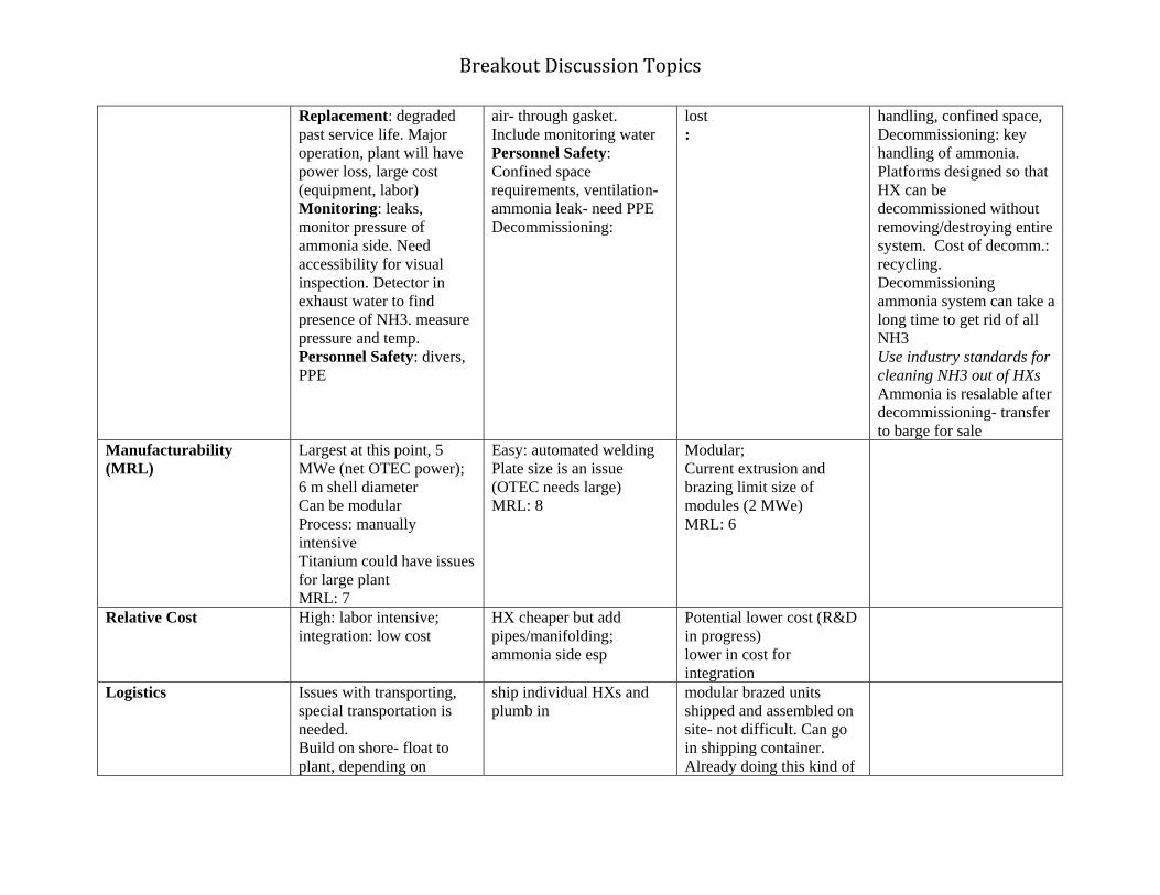
Breakout Discussion Topics
Replacement: degraded past service life. Major operation, plant will have power loss, large cost (equipment, labor) Monitoring: leaks, monitor pressure of ammonia side. Need accessibility for visual inspection. Detector in exhaust water to find presence of NH3. measure pressure and temp. Personnel Safety: divers, PPE
air- through gasket. Include monitoring water Personnel Safety: Confined space requirements, ventilation- ammonia leak- need PPE Decommissioning:
lost :
handling, confined space, Decommissioning: key handling of ammonia. Platforms designed so that HX can be decommissioned without removing/destroying entire system. Cost of decomm.: recycling. Decommissioning ammonia system can take a long time to get rid of all NH3 Use industry standards for cleaning NH3 out of HXs Ammonia is resalable after decommissioning- transfer to barge for sale
Manufacturability (MRL)
Largest at this point, 5 MWe (net OTEC power); 6 m shell diameter Can be modular Process: manually intensive Titanium could have issues for large plant MRL: 7
Easy: automated welding Plate size is an issue (OTEC needs large) MRL: 8
Modular; Current extrusion and brazing limit size of modules (2 MWe) MRL: 6
Relative Cost High: labor intensive; integration: low cost
HX cheaper but add pipes/manifolding; ammonia side esp
Potential lower cost (R&D in progress) lower in cost for integration
Logistics Issues with transporting, special transportation is needed. Build on shore- float to plant, depending on
ship individual HXs and plumb in
modular brazed units shipped and assembled on site- not difficult. Can go in shipping container. Already doing this kind of

Breakout Discussion Topics
location of plant. Equipment requirements; large cost. 5 MW plant; diameter 6 m, road transport can be done, limited import
thing for LNG industry, including offshore.
TRL 8 8 5 What risks are associated with failure? Ammonia safety- leaks Maintain HX to prevent leaks Codes and standards for refrid. industry are applicable to OTEC Coastal ammonia facilities – codes, handling (e.g. ports, barge transp., Leak in piping system- need sensors (refridg. Standards) Sensors needed for air and water leakage Redundancy to mitigate NH3 leak Ammonia pump could fail – need standby (redundancy) Do redundant pumps go above/beyond existing standards? No clear codes for water-NH3 systems Periodically change/calibrate sensors Low temp and pressure make for safer system than other industries Tanks exposed to tropical sunlight- need to be designed to consider this Risk of failure: lower performance- cost issue Biofouling Chlorination failure Water leaking into ammonia (affecting turbine performance) Chloride into ammonia may affect turbine Pump failure Filters/ mist eliminator Leaking from one side to the other; turbine performance

Breakout Discussion Topics
What are the cost drivers? What are possible cost-savings? What research could be done on cost reduction? Materials, manufacturing, assembly/integration, logistics, O&M Size/amount of material, operating in sea water Low deltaT drives large size of HX. Translates to cost driver HX design type/configuration (efficient use of material) Design configurations
Enhanced surfaces No identical applications (not off-the-shelf) What are possible cost-savings?
R&D: (OTEC optimization) Enhanced heat transfer (increasing SA, turbulence, mixing, validated performance) Material (aluminum alloys, plastics, low cost titanium) Fabrication techniques (bonding, brazing, welding, extrusion, etc.)

Breakout Discussion Topics
LUV Life, u-value, cost Pilot plant will help build investment in OTEC Different type of investment (other then R&D) Risk factors: Water leak into ammonia reduces power, affects turbine efficiency Chloride into ammonia may affect turbine If pump fails Does the platform group need to join HX group? Questions from larger group after reportout I: LUV factor L-life U-value V-cost HX performance along with overall performance Would you be able to get quote from manufacturer for HX design for OTEC

Breakout Discussion Topics
What changes have occurred in materials, designs, practices, fabrication, manufacturing, and technology between 1980 and today to make OTEC feasible to pursue on a commercial scale? 1980s Today Materials stainless steel
low volume/high cost of titanium Titanium cost effectiveness (aerospace and
automobile industries) Titanium: developing improved processes
(power plant condenser) Thermally enhanced plastics Aluminum: alloying improved (aerospace
industry) Aluminum: more choices
Designs Plain tubes/Some enhanced tubes
shell and tube Plate frame
Potential new HX designs Plastic or foam HX new emerging techniques
(improving efficiency in processing industry)
Surface enhancements Improved heat transfer coeff. without
incurring pressure drop penalty
Practices - Performance Prediction
High speed/low cost capability of computing Improved analytical and design modeling
techniques Fabrication Extrusions have improved
Aluminum brazing technology (cryogenic, LNG)

Breakout Discussion Topics
Improved welding techniques (for sea water applications; petro industry, LNG, oil, ships, power plant condensers)
Improved instrumentation/quality control Improved coating processes
Manufacturing Improved capability/tooling (petro industry, LNG)
Capacity for larger HX greater automation
Technology - Cycle development
Open cycle concept Hybrid cycle concept developed
Open cycle performance validation Hybrid cycle design Direct contact condensers operational
(geothermal application) Flash evaporators demonstrated Mixed working fluid cycle developed
(demonstrated in geothermal)

6/10/2010
1
Heat Exchangers
Reportout II
Materials, Installation, Scalabilty, Performance
HX Type Shell and tube Plate frame Aluminum Plate Fin
Material Aluminum, Titanium, Stainless steel, Copper-nickel
Stainless steel, titanium
Brazed aluminum
I t ll ti / Si l i Diffi lt l E t if ld iInstallation/ Deployment
Simple; size important in terms of configuration/manifold
Difficult; complex piping system,expensive valving, less flexible for OTEC
Easy to manifold in modular system, easy handling
Scalability Easy; Modular design- 100 MWe --10 MWe modules
Limited; Size and number of plates
Easy to scale up
Performance data and design
Lots of performance data; need enhanced tube
Lots of dataHigh pressure drop HX
Lots of dataDOE test data
Operability• Repair
– Shell and tube: plugging– Plate‐frame: replace individual plates– Plate‐fin: cannot repair on‐site
• Replacement– Shell and tube: degrades past service life (major operation )– Plate‐frame: replace individual HX– Plate‐fin: replace module
• Decommissioning– Key: handling ammonia– Platform designed so that HX can be decommissioned without destroying
whole system– Materials are resalable including NH3– Use industry standards for clean NH3 out of HX
• Personnel Safety– PPE/confined space entry for dry HXs– Divers for submerged HXs– Ammonia handling
Manufacturability
(MRL)
modularProcess: manually
intensiveMRL: 7
Easy: automated welding
Plate size is an issue
MRL: 8Modular;MRL: 6
High: labor HX cheaper but
add Potential lower cost
(R&D in
Relative Cost
intensive; integration: low cost
pipes/manifolding; ammonia side esp.
progress)lower in cost for
integration
Logistics
Issues with transportation
Build on shore-float to plant
ship individual HXs and plumb in
modular brazed units shipped and assembled on site
TRL 8 8 5

6/10/2010
2
What risks are associated with failure?
• Ammonia safety‐ leaks– Codes and standards for refrig. industry are applicable to OTEC
– Leak in piping system‐ need sensors (refrig. Standards)– Sensors needed for air and water leakage– Ammonia pump could fail – need standby (redundancy)– No clear codes for water‐NH3 systems– Periodically change/calibrate sensors
• Low temp and pressure make for safer system than other industries
• Risk of failure: lower performance ‐ cost issue– Biofouling– Corrosion
What are the cost drivers?
• Low deltaT drives cost (large size required)
– Materials
– Assembly/integration
Manufacturing– Manufacturing
– Logistics
– O&M
What are possible cost‐savings?
• Performance enhancements (reduce size of HX)
– Surfaces (increasing SA, turbulence, mixing)
Configuration– Configuration
– Surface treatments
– Optimization
• Cost Reduction
– Materials (e.g. plastics, different alloys)
What are the hurdles?
• HX industry not motivated to provide optimized units to meet OTEC needs
• Time to test and evaluate different designs
Q lif i l i f i• Qualifying aluminum manufacturing processes
• Chlorination acceptable

6/10/2010
3
What is the development time frame for the technologies associated with HXs?
• 5 MWe (12‐18 month)
• Commercial Design: 1 year
• Commercial Manufacturing: 2‐3 years

APPENDIX E:
Platform Mooring
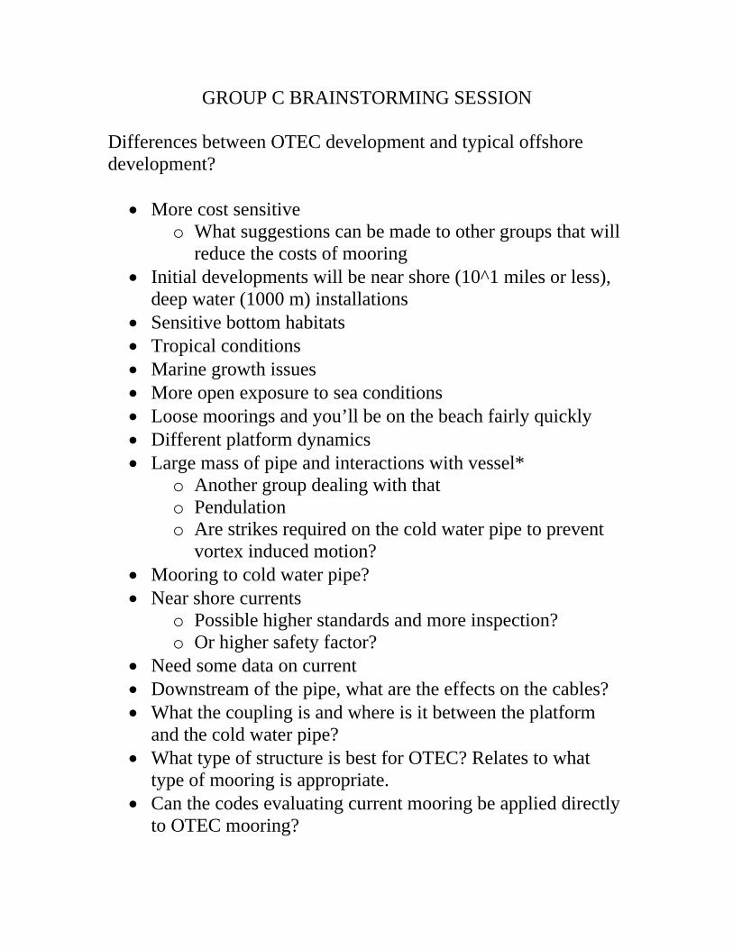
GROUP C BRAINSTORMING SESSION
Differences between OTEC development and typical offshore development?
More cost sensitive o What suggestions can be made to other groups that will
reduce the costs of mooring Initial developments will be near shore (10^1 miles or less),
deep water (1000 m) installations Sensitive bottom habitats Tropical conditions Marine growth issues More open exposure to sea conditions Loose moorings and you’ll be on the beach fairly quickly Different platform dynamics Large mass of pipe and interactions with vessel*
o Another group dealing with that o Pendulation o Are strikes required on the cold water pipe to prevent
vortex induced motion? Mooring to cold water pipe? Near shore currents
o Possible higher standards and more inspection? o Or higher safety factor?
Need some data on current Downstream of the pipe, what are the effects on the cables? What the coupling is and where is it between the platform
and the cold water pipe? What type of structure is best for OTEC? Relates to what
type of mooring is appropriate. Can the codes evaluating current mooring be applied directly
to OTEC mooring?

Depending on the production method of OTEC, how hazardous is the ammonia and how close is it to the shore, will this drive new standards?
Do you require additional SF for moorings depending on OTEC production methods?
For future commercial is there a product that will be off-loaded that will affect the mooring system, with non-weathervaining system will additional structure systems affect the mooring?
Some areas that are envisioned for plant installation do not have the infrastructure capabilities
Design of mooring system and extra equipment will have to consider
How many risers are required? assumed 1 but you may want more than 1
Single point mooring will require swivel for power cable Is there a single point mooring advantage for some locations? Are their percentages of allowable motions available?
* Deal with other groups but may affect mooring costs
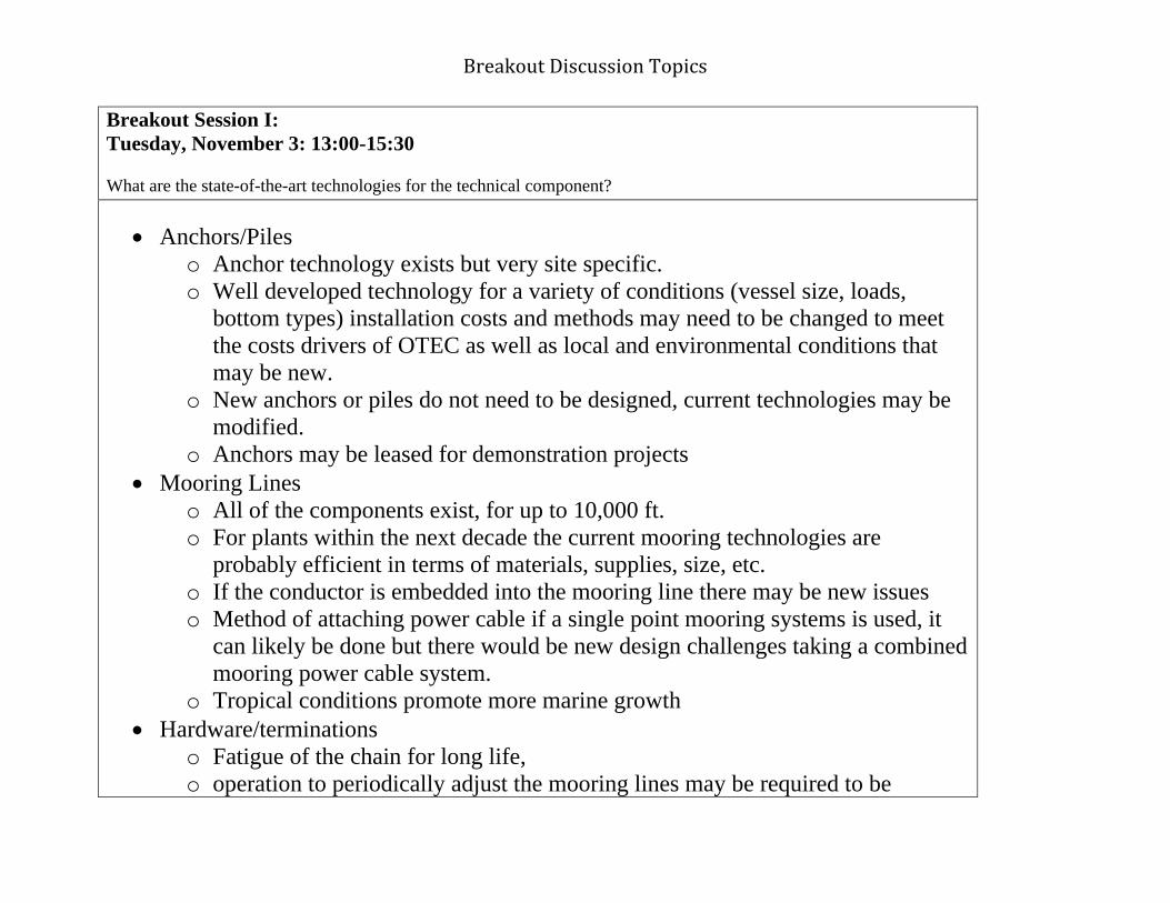
Breakout Discussion Topics
Breakout Session I: Tuesday, November 3: 13:00-15:30 What are the state-of-the-art technologies for the technical component?
Anchors/Piles o Anchor technology exists but very site specific. o Well developed technology for a variety of conditions (vessel size, loads,
bottom types) installation costs and methods may need to be changed to meet the costs drivers of OTEC as well as local and environmental conditions that may be new.
o New anchors or piles do not need to be designed, current technologies may be modified.
o Anchors may be leased for demonstration projects Mooring Lines
o All of the components exist, for up to 10,000 ft. o For plants within the next decade the current mooring technologies are
probably efficient in terms of materials, supplies, size, etc. o If the conductor is embedded into the mooring line there may be new issues o Method of attaching power cable if a single point mooring systems is used, it
can likely be done but there would be new design challenges taking a combined mooring power cable system.
o Tropical conditions promote more marine growth Hardware/terminations
o Fatigue of the chain for long life, o operation to periodically adjust the mooring lines may be required to be

Breakout Discussion Topics
available on the vessel o Shallow water and marine fouling impact on equipment lifespan and load, and
maintenance cycle o Equipment to support the high power cables such as slip rings, strain reliefs,
terminations Integrity monitoring instrumentation
o Design a system that can be replaced in a period Service and inspection Installation equipment/vessels
o Exist but may need to be modified based on location and economics Codes and standards
o Review and modification for site specific conditions and hazards Demobilization/recovery/restoration
o Exist but may need to be modified based on location Analysis modeling tools
o Well developed with a strong practical backing however they need modification in order to accurately model OTEC plant.
o Does fluid flow in pipeline have a significant impact on the model? Test requirements Met ocean data and site survey
o Couple year data collection program Geotechnical site survey Staging area/facilities and support facilities and proximity Mooring design

Breakout Discussion Topics
o Allow the genesis of the mooring system to be driven by the requirements of the platform and the cold water pipe instead of platforms and designs that are already existing, out of the box thinking may be required to break existing paradigms
o Cost effective o Requirement for disconnect in case of extreme storm/typhoon and hardware
involvement, consideration needs to be made for the power cable Single point mooring
o Fouling o Termination o Surface area o Photec zone
What is the life requirement for the demonstration system? o Detailed requirement of the entire demo system
Permitting o General rules and regulations are in place but have been rescinded
Mooring technology is mature and has been demonstrated in more challenging and demanding environments, it’s a matter of detailing and optimization to make it economic and viable in the environment for which it’s deployed. Assuming that the OTEC platform is not significantly different than systems that exist today. We are assuming a compliant mooring system which will not affect the surface motion and wave frequency response of the platform. Does the cold water pipe de-couple?
Breakout Discussion Topics
Breakout Session III: Wednesday, November 4: 12:45-15:00 1) Are the technologies associated with this component viable? What are the economic factors associated with these technologies? What are the hurdles/limiting factors associated with these technologies? 2) What is the development time frame for the tecnologies associated with this component?

6/10/2010
1
Platform Mooring
Session 2
• Mooring technology is mature and has been demonstrated in more challenging and demanding environments, it’s a matter of detailing and optimization to make it economic and viable in the environment for which it’s deployedfor which it s deployed.
• Key driver that will affect the evolution of OTEC mooring systems is cost.
Question 1
• Manufacturability– Achievable with COTS or custom products
– Low to no risk
M bili ti & D l t• Mobilization & Deployment– Achievable with COTS or custom products
– Highest risk, high cost, most opportunity for cost savings
Question 1
• Operability– No special technology required
– Existing techniques sufficient, slight modification may be requiredmodification may be required
• Reliability– No major issues

6/10/2010
2
Question 1
• Logistics– Existing techniques and systems are sufficient
S l bilit• Scalability– Yes
– Some consideration for size and location
– Cost driver
What risks are associated with failure with these processes?
• Manufacturing quality and testing to mitigate unexpected failures.
• Reduced confidence in the system.Risk of inability to deploy effectively & safely• Risk of inability to deploy effectively & safely.
• Significant delay in startup• Additional costs• System failure• Not accurately identifying risk and defining risk mitigation • Limitation on overall size & placement of OTEC
Question 3:What are the cost drivers for this component? What are possible cost-savings? What research
could be done on cost reduction?could be done on cost reduction?
• Cost Drivers: • Spares;• Site conditions; location; water depth• installation, vessel time • material costs• material costs• required performance• installation risk & insurance• labor cost• permitting & regulations• removal and decommissioning costs & requirements

6/10/2010
3
• Cost Savings:• Mooring optimization (single point vs. multi point
mooring)• Coordination of Optimization of design of platform• Less stringent motion and survivability requirementsLess stringent motion and survivability requirements• Citing• Identifying the high cost factors and mitigate them• Optimize the cost of vessel & transportation• Self installing
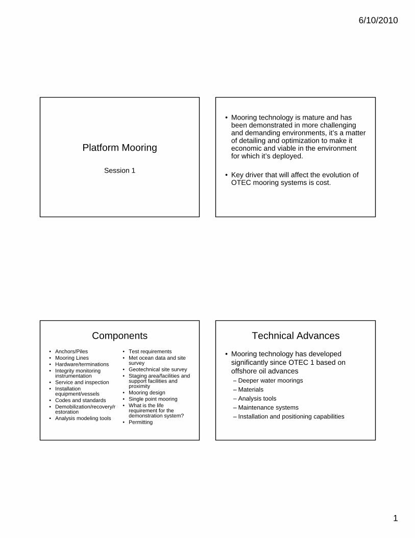
6/10/2010
1
Platform Mooring
Session 1
• Mooring technology is mature and has been demonstrated in more challenging and demanding environments, it’s a matter of detailing and optimization to make it economic and viable in the environment for which it’s deployedfor which it s deployed.
• Key driver that will affect the evolution of OTEC mooring systems is cost.
Components
• Anchors/Piles• Mooring Lines• Hardware/terminations• Integrity monitoring
instrumentationS i d i ti
• Test requirements • Met ocean data and site
survey• Geotechnical site survey • Staging area/facilities and
support facilities and• Service and inspection• Installation
equipment/vessels• Codes and standards• Demobilization/recovery/r
estoration• Analysis modeling tools
support facilities and proximity
• Mooring design• Single point mooring• What is the life
requirement for the demonstration system?
• Permitting
Technical Advances
• Mooring technology has developed significantly since OTEC 1 based on offshore oil advances
Deeper water moorings– Deeper water moorings
– Materials
– Analysis tools
– Maintenance systems
– Installation and positioning capabilities

6/10/2010
2
Assumptions
• The OTEC platform is not significantly different than systems that exist today.
A li t i t ill t ff t• A compliant mooring system will not affect the surface motion and wave frequency response of the platform.
Questions• What are the differences between conventional oil platform
requirements and those of OTEC plants?
• Can a single point mooring be considered?
• What type of structure is best for OTEC? Relates to what type of mooring is appropriatemooring is appropriate.
• How is the platform coupled to the pipe and is there any direct interaction with the cable and what about disconnection?
• Do you require additional safety factor for moorings depending on OTEC production methods?
Components
• Anchors/Piles• Mooring Lines• Hardware/terminations• Integrity monitoring
instrumentationS i d i ti
• Test requirements • Met ocean data and site
survey• Geotechnical site survey • Staging area/facilities and
support facilities and• Service and inspection• Installation
equipment/vessels• Codes and standards• Demobilization/recovery/r
estoration• Analysis modeling tools
support facilities and proximity
• Mooring design• Single point mooring• What is the life
requirement for the demonstration system?
• Permitting

6/10/2010
1
Platform Mooring
Day 3
Priorities
What is the State of the Art• Moorings
– Materials, design, fabrication have advanced to enable moorings to 10k feet, far exceeding the 1k foot limit of 1980, required OTEC mooring depth is 3k + feetfeet
• Infrastructure– Industry has developed which routinely designs and
installs mooring systems in depth up to 10k feet
• Comprehensive codes and standards now exist for deep water moorings
Positioning
• In 1980 positioning of surface and subsurface assets was inadequate for deep water, far from shores for placements. Present technology is sufficient to meet OTEC requirements.– Satellite positioning and shipboard dynamic
positioning allows positioning of surface assets within 1 meter anywhere on the planet, efficiently installed anchor systems
– Underwater acoustic system has advanced accuracy of placement of underwater assets
Materials
– High strength to weight ratio,
Synthetic Mooring lines have increased mooring depths to greater than 10k feet today
High strength to weight ratio, neutrally buoyant materials such as polyester, kevlar, spectra, etc
– High strength steel for use in mooring wire and chain

6/10/2010
2
Anchor
• General advances in anchor technology have led to increased capacities in wide ranged bottom types
Design Analysis Tools
• Advances in software enable deep water moorings to be accurately modeled and analyzed
Validated by field installations in deep water– Validated by field installations in deep water
– Allows optimization of the system
– Broad range of commercially available, industry verified software
Installation and Operation
• Dynamically positioned installation vessels are commonly available
• Under water equipment advances allow safe and effective installation inspectionsafe and effective installation, inspection, maintenance, and recovery in deep water

Platform MooringPlatform Mooring
Day 3
Research NeedsResearch Needs

Research NeedsResearch Needs
• Investigate and be flexible to new paradigms and g p gdesigns relevant to OTEC needs
• Investigate effective anchoring systems in volcanic rock• Investigate techniques that require minimal equipment• Investigate techniques that require minimal equipment
for mooring & power cable installation• Investigate effective mooring systems on high slope
b ttbottoms• Increase the fidelity of tools to improve capability to allow
overall system optimizationy• Advance codes and standards to reflect OTEC systems

APPENDIX E:
Platform/Pipe Interface

Breakout Session II: GROUP D Wednesday, November 4: 10:15-12:15 Discuss the entire life cycle that needs to be considered for each component. Address the following:
1) manufacturability, 2) operability, 3) reliability, 4) logistics, 5) scalability
with respect to: fabrication, deployment, construction, and installation; operation and maintenance (including cleaning, repair, and
replacement); monitoring component performance; personnel safety and emergency preparedness; and decommissioning?
• What risks are associated with failure with these processes?
• What are the cost limiting factors for this component? What are possible costs-savings? What research could be done on cost reduction?
Comments or Questions
- Decommissioning o pipe/platform interface may need be detachable and able to be reattached o What do you do with the pipe?
- Initial pilot off Oahu o Can it be moved?
TLR
- Need to attach pipe to platform o Rigid or Gimbal? (Design Decision)
- CWP needs to be detachable at least one time - CWP Optionally able to be reattached – dependent on relocation area - Need to have some level of pipe recovery - Survivable for duration of plant life
o Corrosion, etc - Must be able to attach 4m pipe - Interface may need angle of motion (Design Consideration) - Interface Sealant - Compatible with CWP construction

Manufacturing - Design issue but not a factor of “can we build it?” - Gimbal
Operability
- Performance - Are there issues with making this work?
Reliability
- Reliable over the design life (20 yrs)? - Which is most likely to be accommodating to an extreme event? - Not solely longevity
Ship-Shape
- Makes relocation more realistic Logistics
- Depends on fabricating on vs. off - Personnel Safety and Emergency preparedness
o Fixed = safer? - Fixed
o Vertical Oil industry uses existing technologies (for 1m pipe)
o Horizontal - Gimbal
o Horizontal Maintainability
- Fixed - Gimbal
o Lubrication o Materials
- Flex o Involves hose o Hose wears out two reconnections
Scalability
- 4 to 10m Risk
- Install/Deinstall vs. Operation o Deinstallation easier with self-supporting pipe o Likelihood of self-supporting buoyant pipe?
- Probability of Failure o Loss of Pipe o Leakage

- Fixed - Gimbal
o Moving parts Pipe that will hold itself up and one that won’t
- Self-supporting Pipe o OTEC 1 o using buoyancy and weight o Easier for horizontal build
- Hanging Pipe o Fundamental issue – heavy o May or may not need dead weight at bottom
Decommissioning
- Large driver - Self-supporting pipe better - Can you attach flotation on to a hanging pipe? - Will the handling system be able to raise and lower the pipe? - Interface must be detachable - Can we detach dead weight?
Relocation
- if we build heavy pipe, then new pipe must be built - if we build self supporting vertical or horizontal pipe, then save those costs

Breakout Session III:GROUP D Wednesday, November 4: 12:45-15:00
• What are the cost limiting factors for this component? What are possible costs-
savings? What research could be done on cost reduction? • Are the technologies associated with this component viable? What are the
economic factors associated with these technologies? What are the hurdles/limiting factors associated with these technologies?
• What is the development time frame for the technologies associated with this
component Off-Shore Industry
- A lot of technology has already been developed - A lot of knowledge exists that should be tapped into
Someone needs to discuss operations Risks in a horizontal build pipe are greater than a vertical build pipe Manufacturing Orientation Horizontal
- Implies self-supporting and manufactured on land Vertical
- Implies configured on platform Cost Drivers
- Gimbal vs. Fixed - Relative motion of pipe vs. platform - Complexity of handling system - Buoyancy costs - Trade-off between land fabrication vs. platform fabrication
Decommissioning is bigger driver than relocation Technologies viable
- Dimensions and material are issues What is the time frame associated with developing an interface?
- 2 years or less - Depends on path taken (maybe 2 years or less) - 2 years - 2 years - Custom equipment: 2 years or less - Design is associated with pipe and platform: 3 years - Custom pouring, forging: 3-4 years

- We are not considering a developing stage Is this a development time frame? - manufacturing time would be shorter than proposed

Breakout Session IV: GROUP D Thursday, November 5: 9:15-15:00
1. Now and then a. Hydromechanical Structure – not sure if bounds have been made b. Know how to do deep water work c. 20 years of deep water experience d. It is an industry – deep water: didn’t exist before
i. Industrial base ii. Code
iii. Standards iv. Control Technologies - handling v. Better understood
e. Data collection and analysis f. Sensor technology – know the loads g. No cheap buoyancy h. Material
i. Composite improvements (materials and processes) 2. Research priorities
a. Three previously mentioned b. Want to expand
i. Electrical Modeling ii. System wearing
1. Does technology today provide us acceptable risk? 2. Analytical simulation specific to OTEC
c. Modeling failure mode

6/10/2010
1
Group D:Platform/Pipe Interface
“Where it all comes together”Where it all comes together
Baseline Parameters for Workshop OTEC Discussions
•Offshore•FloatingM d•Moored
•Cable to shore•5‐10 MWe scalable to commercial scale
•Potentially relocatable
Interface Requirements• Need to attach pipe to platform
– Rigid or Gimbal? (Design Decision)
• CWP needs to be detachable at least one time• CWP Optionally able to be reattached – dependent on
relocation area• Need to have some level of pipe recoveryp p y• Survivable for duration of plant life
– Corrosion, etc
• Must be able to attach 4m pipe• Interface may need angle of motion (Design Consideration)• Interface Sealant• Compatible with CWP construction
CWP Manufacturing Orientations

6/10/2010
2
CWP Configurations
Hanging Self-supported
Life Cycle Considerations
Fixed Gimbal Flex
G G Y
G G G
Y1 G G
Vertical Build Y G Y
Manufacturability
Operability
Reliability
Vertical Build Y G Y
Horizontal Build R R G
G Y R
G Y R
1Dependent on platform but also imposes risk on to CWP
Maintainability
Scalability
Logistics
Risks• If interface detaches with hanging pipe, then the pipe sinks
• If interface detaches with self‐supporting pipe, then the pipe is available to be reconnected
• If interface leaks, then performance degradation• If interface leaks, then repair is difficult• If horizontal build, then installation and deinstallation logistics are more complicated
• If vertical build, then handling system failure could result in loss of pipe
What are the cost drivers for the interface?
• Gimbal vs. Fixed (Flex not scalable)• Decommissioning• Relative motion of pipe vs. platform, especially during fabrication
• Complexity of handling system• Buoyancy costs• Trade‐off between land fabrication vs. platform fabrication
• Coupling/Decoupling

6/10/2010
3
What are possible costs‐savings? • Refined analysis and model tests
• Utilize existing technologies
– Scalable technologies
• Material choices
More rob st– More robust
– Corrosion
• Manufacturing process selection
• Relocatable pipe
• Economy of scale
What research could be done on cost reduction?
• Find and adapt existing technologies and analysis tools
• Material selection
• Buoyancy
Are the technologies viable? What are the economic factors? What are the
limitations?
• Technologies are viable and have been demonstrated at various scales
Dimensions and material are issues– Dimensions and material are issues
• Cost
• Limitations are manageable with current knowledge
What is the development time frame?
• 1 to 2 years for requirements development to include analysis and model tests
• 1 to 2 years to delivery

6/10/2010
1
Group D:Platform/Pipe Interface
“Where it all comes together”
Then and Now• Hydromechanical Structure• Lack of deep water industry and
experience• Limited analytical capabilities and
capacities• Limited sensor technology• Lack of dynamic underwater cables• Limited survey technology
• Established deep water industry– Industrial base– Code– Standards– Control Technologies (handling)– Better understood
• Improvement in Composites – Materials– Processes
• Improved analytical capabilities and capacity
• Environmental awareness• Improved Sensor technology• Development of underwater tools• Underwater construction techniques• Deep dynamic cables• Survey Technology• Improved engineering process
– Configuration management
OTEC Then OTEC Then

6/10/2010
2
OTEC Now

6/10/2010
3
Heavy Lift Spar

6/10/2010
4
Spar FPSO
Bathymetry Then Bathymetry Now

6/10/2010
5
Platforms Then Platforms Now
Research Requirements
• OTEC system modeling– Dynamic coupled structural modeling of CWP
interface– Mesoscale hydrodynamic modeling
• Deep oceanographic data collection, data mining, and processing
• Strengthening the “weakest link”– Defining and modeling failure modes
• Supply chain integration
Glomar Explorer Gimbal

GROUP D Fixed Gimbal Flex
G G Y
G G G
Y1 G G
Vertical Build Y G Y
Horizontal Build R R G
G Y R
G Y R
1Dependent on platform but also imposes risk on to CWP
Maintainability
Scalability
Logistics
Manufacturability
Operability
Reliability

APPENDIX E:
Pumps and Turbines

Day III/Session IV: Changes since 1980: Pumps and Turbines
Pumps and Turbines have been ready for 30 years
No revolutionary breakthrough in pump/turbine; all advances evolutionary
Electronics starting to be introduced into pumps/turbines to monitor health and status; most
advances will be in outage management/condition based management
Ammonia is probably the most practical working fluid
Move toward a desire to create a sustainable system where system can function without
external hydrocarbon inputs making it less susceptible to shifts in hydrocarbon availability and
cost.
Pumps exist today for a 10 mW; for a 100 mW commercial scale pumps would need to be
ganged together
Seaborne environment (roll, pitch, yaw) has proven out turbine machinery over worse or
equivalent situations.
Petroleum industry has 30 years of additional experience working in increasingly harsh
environments (due to less conveniently available oil) and much has been learned about
operations, methods and materials.
OTEC‐style plant in India that produces Freshwater – more expensive than traditional
desalinization methods, however operational and works.
Many attempts since 1980; 250 kW open cycle at NELHA, 1996‐2000 50 kW Hx Testing (NEHLA),
2005 Diego Garcia Feasibility Study, 2006 0TEC Study Makai SBIR, 2007‐2008 10 MW Pilot Plant
Design by Lockheed Martin.

Breakout Discussion Topics
Breakout Session I: GROUP E Tuesday, November 3: 13:00-15:30 What are the state-of-the-art technologies for the technical component?

Breakout Discussion Topics

Breakout Discussion Topics
Breakout Session II: Wednesday, November 4: 10:15-12:15 1) What processes (e.g., equipment, personnel) of the technology are associated with:
i. Fabrication, deployment, construction, and installation; ii. Operation (including monitoring) and maintenance (including cleaning, repair, and replacement);
iii. Monitoring component performance; iv. Personnel safety and emergency preparedness; and v. Decommissioning?
2) What risks are associated with failure with these processes?
Notes: What are the components: (turbines) Blades, some form of stainless steel Casing, welded or cast steel Rub strips, stainless steel Shafts, low alloy steel Sleeve baring, no fatigue limit Manufacturability: Turbine rotor (7-8MW) single piece forging, not changeable, no erosion or foreign object damage Open die-press forging Not too difficult to forge, limits would be tip speed goes up, centrifugal stress goes up, adds cost Okay for 5-10MW, lots of experience, forging capability exists, manufacturing exists Oil getting into the system through seals of the rotating equipment Need to minimize seal leakage (should be a state-of-the art technology)

Breakout Discussion Topics
Leakage should be working fluid out, not oil in Most manufacturers would know how to handle this Ammonia turbines reliability, don’t have a database yet Some manufacturers have ammonia turbines as a standard product (What are the applications for these? Refrigerant.. Talking about radial flow turbines Scalability would be on a modular basis Capital cost for 10MW prototype huge compared to the cost for the 100MW There are other issues for multiple turbines: all the piping, valving, shafts etc. Assessment needs to be completed Blades: The blades on the roto-flow turbine, machined and non-removable Axial, blades are replaceable individually Can be: Forged, machined, or cut out of plate with wire EDM and machined Reliability and manufacturability: Depend on the process Dynamic testing needs to be done (risk reduction activity) Scalability: What limits the size and speed is the blade tip speed, need to be subsonic Axial Flow turbine, can add stages, but get more energy taken out on the last few stages Reliability is there for these turbines Logistics: Maintenance aspect: have redundancy, in a small plant have at least 3 turbines, maybe 4, assume there are 2 operating At these sizes the turbines shouldn’t be too expensive, might pay to have an extra turbine or inventory parts Manufacturers have repair services

Breakout Discussion Topics
However with ammonia, might have to have inventory of parts for 1 turbine set Can always get the parts but there is a lead time, would want back up What is the periodic shut-down, 1 annual inspection, 1st inspection is ~5 years Don’t have a database on ammonia turbines, would want to inspect Invasive vs. noninvasive monitoring Noninvasive: ensures do not mess up the turbine through inspection Sensors are being put in Plant will be shut-down for other maintenance issues The potential of erosion blades Density of ammonia less than the density of water In some steam-turbine, lots of erosion, but almost no fatigue failures Don’t think that will be a problem with ammonia, because of the lower density, might be harder to cavitate (Liquid droplet erosion) Ammonia will form a bubble, but won’t have the same impact as water We are not sure whether liquid droplet erosion will occur against a steel substrate in an ammonia environment at high speeds. Need to set-up a whole materials list for what you are going to need in inventory When you have an outage for some other reason, what do we go and do for the turbines? Turbine is not going to be driving the shutdown Need a set of critical parts for the turbines, not a full turbine as extra Need to have multiple turbines so you can shut down part of the plant (Allows modularity) If you shut down one turbine you are shutting down two heat exchangers Do not want stagnant water in your heat exchangers On the pump side, would make sense to have an extra pump Always have multiple pumps, need excess capacity

Breakout Discussion Topics
Risks: Expect turbine to be the most reliable component Environment is inert and the machine design practices are good Risk reduction: having spare parts available Foreign object damage off the pump that could damage the turbine Failure of a valve or pump or strainer, weld icicles could break off which might not come off in the flush Radiography will be done, ultra-sonics as well, surface inspection from the outside Mitigation to this risk is training welders and having automated machinery Oil leak into the ammonia side would: impact the performance, might get cavitation or erosion Would change out the working fluid Platform motion probably will not have additional stress on the turbines Most ships powered by steam turbines, motion not a problem Cost Drivers: Operational mode, spare part inventory Life cycle: 30 years, so why skimp on capital cost? Changing types of stainless steel might not save that much money Lead times for large turbines could be on the order of a year – 18months
Pumps: Axial flow for large water pumps Components: Structure, motor, shaft, impeller, substation Maximum size limit on some of these pumps for the larger plant, driving towards multiple pumps Might want to have two oversized pumps each would be able to the whole flow-rate

Breakout Discussion Topics
560,000kg/sec for 100MW, warm water pump 460,000 kg/sec for 100MW, cold water pump Problem with submersible pump, if something goes wrong have to pull it out. Need to be able to do that easily Non-submersible can fix Wide range of configurations for these pumps Need to consider both submersible and non Pumps are basically available. Might not be quite off the shelf, but close enough, always something that needs to be tweaked Databases are there Several vendors would be able to manufacture these pumps Warm water pump issue with the organisms Did not seem to be a problem when talking to pump manufacturers Lot of pump manufacturers of different quality Depending on what they are doing, operability and reliability differs Logistics: double the pumping in case of bypass Pumps are pretty reliable Pump manufacturer will have a design that is almost what you need and it will just be a tweak In terms of reliability, operability, manufacturability, pumps are pretty standard Operation and Maintenance: submersibles will have to be inspected more frequently Circuit performance is monitored Typically pumps are not highly sensitive to erosion, corrosion Have a wide variety of materials to pick to prevent erosion and corrosion

Breakout Discussion Topics
Materials are not high cost drivers Mitigation: Redundancy Spare parts inventory for non-submersible pumps For submersibles would need a spare pump If something happens to the submersible pump would ship back to the manufacturer Life Cycle should be the primary driver Should spend according to the life cycle Lead times: ~ 1 year – 18 months If they are using air-cooled generators could get corrosion and shorting out Decommissioning: Turbines shaft/rotor- carbon steel or low alloy steel Turbine blades- 12% chromium stainless steel or higher alloy steel Turbine casing- carbon steel Misc. parts- bearings (babbit) – can be re-melted, valves and seals – stainless steel Pumps: Casings – carbon steel (may have epoxy coating or other corrosion protection) Impeller- stainless steel Motor- combination of copper, solder, insulation material; non-metallic material, Shaft casing- carbon steel Conclusion: > 85-90% recyclable materials Contaminants associated with decommissioning- oils + solvents

Breakout Discussion Topics

Breakout Discussion Topics
Life Cycle- Turbines manufacturability
Not difficult at 5-10 MW and larger outputs up to 100 MW. Standard manufacturing practices in existence (forging, machining & casting).
operability Fully adaptable to platform environment reliability Most reliable component in the system. Long periods between routine inspections. logistics Stock critical spares (rotors, seals, bearings, etc.)
Periodic inspections opportunities during downtimes caused by other components. 18-24 month lead time to delivery.
scalability 5-10 MW Turbine (radial flow) has size limit. Larger size axial turbines, add blade length or number of blade stages to achieve greater output or efficiency.
Water Pumps manufacturability
Max impeller diameter 7ft. Wide range of design base configurations available from multiple vendors.
operability Warm water pump issue with organisms. reliability Pumps have proven high reliability. Multiple or oversize pumps to sustain operation. logistics Depot repair for submersible pumps; organic partial repair potential for non-submersible.
12-18 month lead time. scalability Maximum size limit on some of these pumps for the larger plant, driving towards multiple
pumps. Working Fluid Pumps manufacturability
Wide range of design base configurations available from multiple vendors.
operability Ammonia pumps are self lubricating. reliability Pumps have proven high reliability. Multiple pumps to sustain operation. logistics 12-18 month lead time. Critical spares necessary. scalability No scaling issues. Scaling is achieved through module replication. Assumptions: -Closed cycle operating system

Breakout Discussion Topics
Decommissioning: Turbines- Turbines shaft/rotor- carbon steel or low alloy steel Turbine blades- 12% chromium stainless steel or higher alloy steel Turbine casing- carbon steel Misc. parts- bearings (babbit) – can be re-melted, valves and seals – stainless steel Pumps- Casings – carbon steel (may have epoxy coating or other corrosion protection) Impeller- stainless steel Motor- combination of copper, solder, insulation material; non-metallic material, Shaft casing- carbon steel Conclusion: > 85-90% recyclable materials Contaminants associated with decommissioning- oils + solvents Viability of technologies: All commercially available technology that can be altered to fit these requirements. Economic factors: All components are technologically mature. All pumps and turbines 80-90% efficient. Limiting factors: None Development time frame: Required custom modifications: 18-24 months for turbine 6 -12 months for pumps Dependent on size of unit.

Breakout Discussion Topics

Breakout Discussion Topics
Breakout Session III: Wednesday, November 4: 12:45-15:00 1) Are the technologies associated with this component viable? What are the economic factors associated with these technologies? What are the hurdles/limiting factors associated with these technologies? 2) What is the development time frame for the tecnologies associated with this component?
Viability of technologies: All commercially available technology that can be altered to fit these requirements. Economic factors: All components are technologically mature. All pumps and turbines 80-90% efficient. Limiting factors: None Development time frame: Required custom modifications: 18-24 months for turbine 6 -12 months for pumps Dependent on size of unit.

Breakout Discussion Topics
Foreign object damage from heat exchanger piping: How will FOD such as slag or welding residue be eradicated from the system prior to operation? Should not be a problem with adequately trained welders, quality control and non-destructive testing. If not adequately addressed, severe damage to turbines and pumps will result. Influent screen to prevent damage. Roll, pitch and yaw of the platform and how it affects alignment of turbine and pumps: Efficiency vs. allowable movement? Ships & platforms already deployed at sea with turbines (30 year design life)– operational design for 0.06G with max of 0.15 Survival design 0.5G (kinematic and gravitational effects) Bearings overdesigned to handle the shock loads. Concern: Working fluid (ammonia) contaminated with oil- More of an issue for heat exchangers (fouling). Prevention + monitoring – maintaining seals Removal-
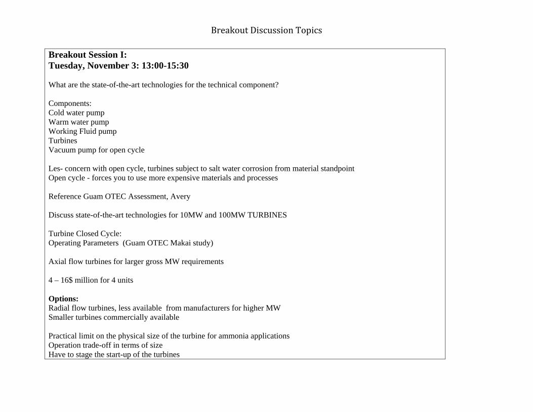
Breakout Discussion Topics
Breakout Session I: Tuesday, November 3: 13:00-15:30 What are the state-of-the-art technologies for the technical component? Components: Cold water pump Warm water pump Working Fluid pump Turbines Vacuum pump for open cycle Les- concern with open cycle, turbines subject to salt water corrosion from material standpoint Open cycle - forces you to use more expensive materials and processes Reference Guam OTEC Assessment, Avery Discuss state-of-the-art technologies for 10MW and 100MW TURBINES Turbine Closed Cycle: Operating Parameters (Guam OTEC Makai study) Axial flow turbines for larger gross MW requirements 4 – 16$ million for 4 units Options: Radial flow turbines, less available from manufacturers for higher MW Smaller turbines commercially available Practical limit on the physical size of the turbine for ammonia applications Operation trade-off in terms of size Have to stage the start-up of the turbines

Breakout Discussion Topics
State of the art for radial flow turbines: machined from one piece of metal, has to do with the size of metal you can get Reasonable limit, to make these turbines Axial flow turbines: Control issues, different valve system, bypass Sizable, Vendors make a lot of smaller turbines and the development cost for larger turbines would be big For a 10MW facility: 2 radial flow turbines each at 7 – 8 MW (gross) Would get modularity, redundancy, reliability Some would look at increased number of smaller turbines 4 radial flow turbines, high-speed Need to add a gear-box, parasitic losses associated with this, and increased cost These options are commercially available Toshiba, GE Rotoflow, Mitsubishi, Eliott, Hitachi Costs: 4- 16million for 4 units 10million for 2 units 10MW State – of – the –art Closer to 25MW size 100MW options: Add modules, not going any larger in terms of turbine size Trade-study recommended: axial, radial, modules, cost

Breakout Discussion Topics
Unique requirements for ammonia instead of steam Market need: turbines in this size range need to be designed specifically for ammonia Control valves to designed to ensure less pressure loss upstream of the turbine Easier design, but fewer bidders 1st product engineering Ammonia turbines are specialty items and require development Pumps: State of the Art: Types: Submersible or non-submersible High efficiency pump with high efficiency motors These pumps commercially available Price might need to come down Enough demand in the market to develop higher efficiency motors (OTEC funding would not be necessary) 8 coldwater and 8 warm water pumps 200,000gpm each (OTC Design) for 100MW 100MW 460,000 kg/sec coldwater 209,000gpm (Makai, OTEC) 560,000 kg/sec for warm water 255,000gpm warm water The number of pumps, varies depending on vendor Efficiencies: 87 – 92% Submersible, axial flow impeller design

Breakout Discussion Topics
10MW 2 cold water pumps would be available as state of the art today Available from 2 vendors ~9month to a year lead time Working Fluid Pump (ammonia): NH3 Parameters: OTC 8 working fluid feed pumps (1operating, 1 standby) 2 per heat exchanger 8 recycle pumps Total: 16 pumps These pumps are commercially available and inexpensive Lowest cost hardware in the system Require more maintenance Limited application for hybrid cycles in offshore projects Would need to transport the water to shore (economical?) How far offshore is it? What will it cost to ship the water back to mainland? Or produce the water onshore using the power produced from OTEC A study needs to be completed to determine offshore vs. onshore water production Vacuum pump: commercially available at this scale

Breakout Discussion Topics
Closed Cycle Operating Parameters:
State – of – the Art Technologies
Turbine
100 MW (135MW) Inlet ammonia temp is 21 C = 69.8 F Outlet ammonia temp is 9.7 C = 49.46 F Pressure in: 890 kPa = 129.1 psi Pressure out: 609 kPa = 88.3psi Flow rate: 3566 kg/s Efficiency not listed (Guam OTEC Makai study) 20 MW Inlet temp: 69.6 F Pressure inlet: 127.9 psia Exit Pressure: 90.8 psia Exit temp: 50.9 F (Baseline Designs of Moored and Grazing 40-MW OTEC Pilot Plants George and Richards June 1980 JHU/ APL SR – 80-1A
Cold Water Pump
Flow rate: Operation efficiency: Motor efficiency: Head:
Warm Water Pump

Breakout Discussion Topics
Working Fluid Pump

Breakout Discussion Topics
Topic State of the Art Engineering Challenge
Processes
Fabrication
Deployment
Construction
Installation
OMR&R
Environmental Monitoring
Safe Operating Procedures

Breakout Discussion Topics
Decommissioning RISKS ASSOCIATED WITH PROCESS FAILURE
COMPONENT VIABILITY
ECONOMIC FACTORS
HURDLES/LIMITING FACTORS
DEVELOPMENT TIME FRAME

Breakout Discussion Topics
Breakout Session II: Wednesday, November 4: 10:15-12:15 1) What processes (e.g., equipment, personnel) of the technology are associated with:
i. Fabrication, deployment, construction, and installation; ii. Operation (including monitoring) and maintenance (including cleaning, repair, and replacement);
iii. Monitoring component performance; iv. Personnel safety and emergency preparedness; and v. Decommissioning?
2) What risks are associated with failure with these processes?
Notes:

Breakout Discussion Topics
Topic State-of-the-art: Engineering Challenge PROCESSES:
Fabrication Deployment Construction Installation OMR&R Environmental Monitoring Safe Operating Procedures
Decommissioning Risks Associated with Process Failure
Component Viability Economic Factors Hurdles/Limiting Factors Development Time Frame

Breakout Discussion Topics
Breakout Session III: Wednesday, November 4: 12:45-15:00 1) Are the technologies associated with this component viable? What are the economic factors associated with these technologies? What are the hurdles/limiting factors associated with these technologies? 2) What is the development time frame for the tecnologies associated with this component?

6/10/2010
1
Pumps & TurbinesTurbines
manufacturability Not difficult at 5-10 MW and larger outputs up to 100 MW. Standard manufacturing practices in existence (forging, machining & casting).
operability Fully adaptable to platform environment
reliability Most reliable component in the system. Long periods between routine inspectionsbetween routine inspections.
logistics Stock critical spares (rotors, seals, bearings, etc.) Periodic inspections opportunities during downtimes caused by other components. 18-24 month lead time to delivery.
scalability 5-10 MW Turbine (radial flow) has size limit. Larger size axial turbines, add blade length or number of blade stages to achieve greater output or efficiency.
Assumptions:-Closed cycle operating system
Pumps & TurbinesWater Pumps
manufacturability Max impeller diameter 7ft. Wide range of design base configurations available from multiple vendors.
operability Warm water pump issue with organisms.
reliability Pumps have proven high reliability. Multiple or oversize pumps to sustain operationpumps to sustain operation.
logistics Depot repair for submersible pumps; organic partial repair potential for non-submersible. 12-18 month lead time.
scalability Maximum size limit on some of these pumps for the larger plant, driving towards multiple pumps.
Assumptions:-Closed cycle operating system
Pumps & TurbinesWorking Fluid Pumps
manufacturability Wide range of design base configurations available from multiple vendors.
operability Ammonia pumps are self lubricating.
reliability Pumps have proven high reliability. Multiple pumps to sustain operationsustain operation.
logistics 12-18 month lead time. Critical spares necessary.
scalability No scaling issues. Scaling is achieved through module replication.
Assumptions:-Closed cycle operating system
DecommissioningTurbines‐• Turbines shaft/rotor‐ carbon steel or low alloy steel • Turbine blades‐ 12% chromium stainless steel or higher alloy steel • Turbine casing‐ carbon steel • Misc. parts‐ bearings (babbit) – can be re‐melted, valves and seals – stainless steel
Pumps‐• Casings – carbon steel (may have epoxy coating or other corrosion protection)• Impeller‐ stainless steel• Motor‐ combination of copper, solder, insulation material; non‐metallic material, • Shaft casing‐ carbon steel
Conclusion‐• > 85‐90% recyclable materials• Contaminants associated with decommissioning‐ oils + solvents

6/10/2010
2
Viability of technologiesAll commercially available technology that can be altered to fit these requirements.
Economic factors:• All components are technologically mature. All pumps and turbines 80‐90%
efficient.
Limiting factors:• None
Development time frame:• Required custom modifications:• 18‐24 months for turbine• 6 ‐12 months for pumps
• Dependent on size of unit.

6/10/2010
1
Pumps and Turbines
Breakout Session 1: State-of-the-Art Technologies
Assumptions:
• Closed cycle leading contender for near term commercialization
References:
G OTEC F ibilit A t• Guam OTEC Feasibility Assessment
• Baseline Designs of Moored and Grazing 40-MW OTEC Pilot Plants
• Renewable Energy From the Ocean
• OTC Study
Components Addressed:
• Turbines
• Pumps– Cold Water Pump
W W t P– Warm Water Pump
– Working Fluid Feed Pumps
– Vacuum Pump (Open/Hybrid Cycles)
Turbines
• Reviewed Operating Parameters for 30 year period and remained consistent
• Ammonia turbines are specialty items and require additional development time
• Optimization for ammonia working fluid is desirable • Radial Flow for 10MW
– 2 per plant – 7 - 8 MW gross each turbine – Commercially Available, multiple vendors
• Axial Flow for 100MW – Trade study recommended to optimize size for NH3
• For all power levels multiple turbines are required for modularity, reliability, redundancy, operation and maintenance

6/10/2010
2
Cold/Warm Water Pumps • Axial Flow impeller design
• Submersible vs. non
• High efficiency pumps with high efficiency motors
• 87-92% efficiency possible in some configurations
• Commercially available
• Multiple vendors
Working Fluid Pumps
• Feed pumps
• Recycle pumps
• One of the lowest cost items in the system
• Commercially available
• Large Design database established
Vacuum Pumps
• Needed for Hybrid Cycle
• Commercially adaptable database
• Currently used in conventional sea water l d l d f il l t f t tcooled nuclear and fossil plants for start-
up
• Trade off studies need to be performed relative to the location of water production (onshore vs. offshore)

APPENDIX E:
Pumps and Turbines

Day III/Session IV: Changes since 1980: Pumps and Turbines
Pumps and Turbines have been ready for 30 years
No revolutionary breakthrough in pump/turbine; all advances evolutionary
Electronics starting to be introduced into pumps/turbines to monitor health and status; most
advances will be in outage management/condition based management
Ammonia is probably the most practical working fluid
Move toward a desire to create a sustainable system where system can function without
external hydrocarbon inputs making it less susceptible to shifts in hydrocarbon availability and
cost.
Pumps exist today for a 10 mW; for a 100 mW commercial scale pumps would need to be
ganged together
Seaborne environment (roll, pitch, yaw) has proven out turbine machinery over worse or
equivalent situations.
Petroleum industry has 30 years of additional experience working in increasingly harsh
environments (due to less conveniently available oil) and much has been learned about
operations, methods and materials.
OTEC‐style plant in India that produces Freshwater – more expensive than traditional
desalinization methods, however operational and works.
Many attempts since 1980; 250 kW open cycle at NELHA, 1996‐2000 50 kW Hx Testing (NEHLA),
2005 Diego Garcia Feasibility Study, 2006 0TEC Study Makai SBIR, 2007‐2008 10 MW Pilot Plant
Design by Lockheed Martin.

Breakout Discussion Topics
Breakout Session I: GROUP E Tuesday, November 3: 13:00-15:30 What are the state-of-the-art technologies for the technical component?

Breakout Discussion Topics

Breakout Discussion Topics
Breakout Session II: Wednesday, November 4: 10:15-12:15 1) What processes (e.g., equipment, personnel) of the technology are associated with:
i. Fabrication, deployment, construction, and installation; ii. Operation (including monitoring) and maintenance (including cleaning, repair, and replacement);
iii. Monitoring component performance; iv. Personnel safety and emergency preparedness; and v. Decommissioning?
2) What risks are associated with failure with these processes?
Notes: What are the components: (turbines) Blades, some form of stainless steel Casing, welded or cast steel Rub strips, stainless steel Shafts, low alloy steel Sleeve baring, no fatigue limit Manufacturability: Turbine rotor (7-8MW) single piece forging, not changeable, no erosion or foreign object damage Open die-press forging Not too difficult to forge, limits would be tip speed goes up, centrifugal stress goes up, adds cost Okay for 5-10MW, lots of experience, forging capability exists, manufacturing exists Oil getting into the system through seals of the rotating equipment Need to minimize seal leakage (should be a state-of-the art technology)

Breakout Discussion Topics
Leakage should be working fluid out, not oil in Most manufacturers would know how to handle this Ammonia turbines reliability, don’t have a database yet Some manufacturers have ammonia turbines as a standard product (What are the applications for these? Refrigerant.. Talking about radial flow turbines Scalability would be on a modular basis Capital cost for 10MW prototype huge compared to the cost for the 100MW There are other issues for multiple turbines: all the piping, valving, shafts etc. Assessment needs to be completed Blades: The blades on the roto-flow turbine, machined and non-removable Axial, blades are replaceable individually Can be: Forged, machined, or cut out of plate with wire EDM and machined Reliability and manufacturability: Depend on the process Dynamic testing needs to be done (risk reduction activity) Scalability: What limits the size and speed is the blade tip speed, need to be subsonic Axial Flow turbine, can add stages, but get more energy taken out on the last few stages Reliability is there for these turbines Logistics: Maintenance aspect: have redundancy, in a small plant have at least 3 turbines, maybe 4, assume there are 2 operating At these sizes the turbines shouldn’t be too expensive, might pay to have an extra turbine or inventory parts Manufacturers have repair services

Breakout Discussion Topics
However with ammonia, might have to have inventory of parts for 1 turbine set Can always get the parts but there is a lead time, would want back up What is the periodic shut-down, 1 annual inspection, 1st inspection is ~5 years Don’t have a database on ammonia turbines, would want to inspect Invasive vs. noninvasive monitoring Noninvasive: ensures do not mess up the turbine through inspection Sensors are being put in Plant will be shut-down for other maintenance issues The potential of erosion blades Density of ammonia less than the density of water In some steam-turbine, lots of erosion, but almost no fatigue failures Don’t think that will be a problem with ammonia, because of the lower density, might be harder to cavitate (Liquid droplet erosion) Ammonia will form a bubble, but won’t have the same impact as water We are not sure whether liquid droplet erosion will occur against a steel substrate in an ammonia environment at high speeds. Need to set-up a whole materials list for what you are going to need in inventory When you have an outage for some other reason, what do we go and do for the turbines? Turbine is not going to be driving the shutdown Need a set of critical parts for the turbines, not a full turbine as extra Need to have multiple turbines so you can shut down part of the plant (Allows modularity) If you shut down one turbine you are shutting down two heat exchangers Do not want stagnant water in your heat exchangers On the pump side, would make sense to have an extra pump Always have multiple pumps, need excess capacity

Breakout Discussion Topics
Risks: Expect turbine to be the most reliable component Environment is inert and the machine design practices are good Risk reduction: having spare parts available Foreign object damage off the pump that could damage the turbine Failure of a valve or pump or strainer, weld icicles could break off which might not come off in the flush Radiography will be done, ultra-sonics as well, surface inspection from the outside Mitigation to this risk is training welders and having automated machinery Oil leak into the ammonia side would: impact the performance, might get cavitation or erosion Would change out the working fluid Platform motion probably will not have additional stress on the turbines Most ships powered by steam turbines, motion not a problem Cost Drivers: Operational mode, spare part inventory Life cycle: 30 years, so why skimp on capital cost? Changing types of stainless steel might not save that much money Lead times for large turbines could be on the order of a year – 18months
Pumps: Axial flow for large water pumps Components: Structure, motor, shaft, impeller, substation Maximum size limit on some of these pumps for the larger plant, driving towards multiple pumps Might want to have two oversized pumps each would be able to the whole flow-rate

Breakout Discussion Topics
560,000kg/sec for 100MW, warm water pump 460,000 kg/sec for 100MW, cold water pump Problem with submersible pump, if something goes wrong have to pull it out. Need to be able to do that easily Non-submersible can fix Wide range of configurations for these pumps Need to consider both submersible and non Pumps are basically available. Might not be quite off the shelf, but close enough, always something that needs to be tweaked Databases are there Several vendors would be able to manufacture these pumps Warm water pump issue with the organisms Did not seem to be a problem when talking to pump manufacturers Lot of pump manufacturers of different quality Depending on what they are doing, operability and reliability differs Logistics: double the pumping in case of bypass Pumps are pretty reliable Pump manufacturer will have a design that is almost what you need and it will just be a tweak In terms of reliability, operability, manufacturability, pumps are pretty standard Operation and Maintenance: submersibles will have to be inspected more frequently Circuit performance is monitored Typically pumps are not highly sensitive to erosion, corrosion Have a wide variety of materials to pick to prevent erosion and corrosion

Breakout Discussion Topics
Materials are not high cost drivers Mitigation: Redundancy Spare parts inventory for non-submersible pumps For submersibles would need a spare pump If something happens to the submersible pump would ship back to the manufacturer Life Cycle should be the primary driver Should spend according to the life cycle Lead times: ~ 1 year – 18 months If they are using air-cooled generators could get corrosion and shorting out Decommissioning: Turbines shaft/rotor- carbon steel or low alloy steel Turbine blades- 12% chromium stainless steel or higher alloy steel Turbine casing- carbon steel Misc. parts- bearings (babbit) – can be re-melted, valves and seals – stainless steel Pumps: Casings – carbon steel (may have epoxy coating or other corrosion protection) Impeller- stainless steel Motor- combination of copper, solder, insulation material; non-metallic material, Shaft casing- carbon steel Conclusion: > 85-90% recyclable materials Contaminants associated with decommissioning- oils + solvents

Breakout Discussion Topics
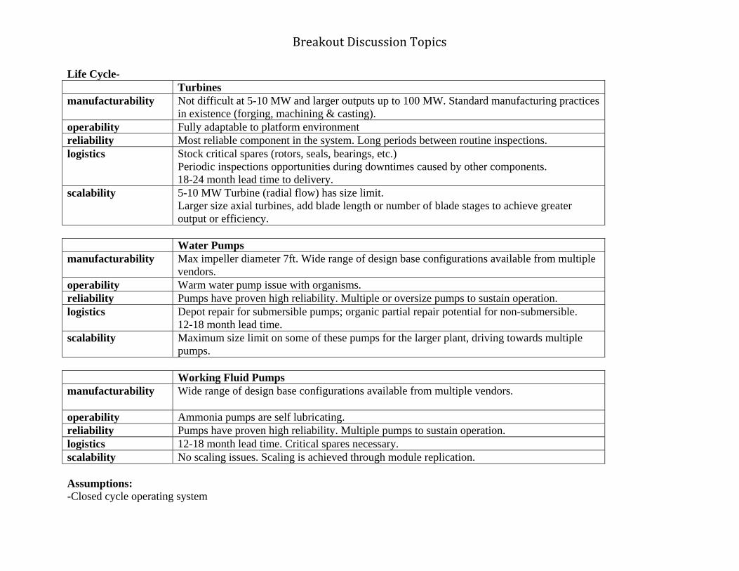
Breakout Discussion Topics
Life Cycle- Turbines manufacturability
Not difficult at 5-10 MW and larger outputs up to 100 MW. Standard manufacturing practices in existence (forging, machining & casting).
operability Fully adaptable to platform environment reliability Most reliable component in the system. Long periods between routine inspections. logistics Stock critical spares (rotors, seals, bearings, etc.)
Periodic inspections opportunities during downtimes caused by other components. 18-24 month lead time to delivery.
scalability 5-10 MW Turbine (radial flow) has size limit. Larger size axial turbines, add blade length or number of blade stages to achieve greater output or efficiency.
Water Pumps manufacturability
Max impeller diameter 7ft. Wide range of design base configurations available from multiple vendors.
operability Warm water pump issue with organisms. reliability Pumps have proven high reliability. Multiple or oversize pumps to sustain operation. logistics Depot repair for submersible pumps; organic partial repair potential for non-submersible.
12-18 month lead time. scalability Maximum size limit on some of these pumps for the larger plant, driving towards multiple
pumps. Working Fluid Pumps manufacturability
Wide range of design base configurations available from multiple vendors.
operability Ammonia pumps are self lubricating. reliability Pumps have proven high reliability. Multiple pumps to sustain operation. logistics 12-18 month lead time. Critical spares necessary. scalability No scaling issues. Scaling is achieved through module replication. Assumptions: -Closed cycle operating system

Breakout Discussion Topics
Decommissioning: Turbines- Turbines shaft/rotor- carbon steel or low alloy steel Turbine blades- 12% chromium stainless steel or higher alloy steel Turbine casing- carbon steel Misc. parts- bearings (babbit) – can be re-melted, valves and seals – stainless steel Pumps- Casings – carbon steel (may have epoxy coating or other corrosion protection) Impeller- stainless steel Motor- combination of copper, solder, insulation material; non-metallic material, Shaft casing- carbon steel Conclusion: > 85-90% recyclable materials Contaminants associated with decommissioning- oils + solvents Viability of technologies: All commercially available technology that can be altered to fit these requirements. Economic factors: All components are technologically mature. All pumps and turbines 80-90% efficient. Limiting factors: None Development time frame: Required custom modifications: 18-24 months for turbine 6 -12 months for pumps Dependent on size of unit.

Breakout Discussion Topics

Breakout Discussion Topics
Breakout Session III: Wednesday, November 4: 12:45-15:00 1) Are the technologies associated with this component viable? What are the economic factors associated with these technologies? What are the hurdles/limiting factors associated with these technologies? 2) What is the development time frame for the tecnologies associated with this component?
Viability of technologies: All commercially available technology that can be altered to fit these requirements. Economic factors: All components are technologically mature. All pumps and turbines 80-90% efficient. Limiting factors: None Development time frame: Required custom modifications: 18-24 months for turbine 6 -12 months for pumps Dependent on size of unit.

Breakout Discussion Topics
Foreign object damage from heat exchanger piping: How will FOD such as slag or welding residue be eradicated from the system prior to operation? Should not be a problem with adequately trained welders, quality control and non-destructive testing. If not adequately addressed, severe damage to turbines and pumps will result. Influent screen to prevent damage. Roll, pitch and yaw of the platform and how it affects alignment of turbine and pumps: Efficiency vs. allowable movement? Ships & platforms already deployed at sea with turbines (30 year design life)– operational design for 0.06G with max of 0.15 Survival design 0.5G (kinematic and gravitational effects) Bearings overdesigned to handle the shock loads. Concern: Working fluid (ammonia) contaminated with oil- More of an issue for heat exchangers (fouling). Prevention + monitoring – maintaining seals Removal-

Breakout Discussion Topics
Breakout Session I: Tuesday, November 3: 13:00-15:30 What are the state-of-the-art technologies for the technical component? Components: Cold water pump Warm water pump Working Fluid pump Turbines Vacuum pump for open cycle Les- concern with open cycle, turbines subject to salt water corrosion from material standpoint Open cycle - forces you to use more expensive materials and processes Reference Guam OTEC Assessment, Avery Discuss state-of-the-art technologies for 10MW and 100MW TURBINES Turbine Closed Cycle: Operating Parameters (Guam OTEC Makai study) Axial flow turbines for larger gross MW requirements 4 – 16$ million for 4 units Options: Radial flow turbines, less available from manufacturers for higher MW Smaller turbines commercially available Practical limit on the physical size of the turbine for ammonia applications Operation trade-off in terms of size Have to stage the start-up of the turbines
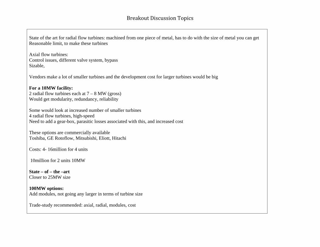
Breakout Discussion Topics
State of the art for radial flow turbines: machined from one piece of metal, has to do with the size of metal you can get Reasonable limit, to make these turbines Axial flow turbines: Control issues, different valve system, bypass Sizable, Vendors make a lot of smaller turbines and the development cost for larger turbines would be big For a 10MW facility: 2 radial flow turbines each at 7 – 8 MW (gross) Would get modularity, redundancy, reliability Some would look at increased number of smaller turbines 4 radial flow turbines, high-speed Need to add a gear-box, parasitic losses associated with this, and increased cost These options are commercially available Toshiba, GE Rotoflow, Mitsubishi, Eliott, Hitachi Costs: 4- 16million for 4 units 10million for 2 units 10MW State – of – the –art Closer to 25MW size 100MW options: Add modules, not going any larger in terms of turbine size Trade-study recommended: axial, radial, modules, cost
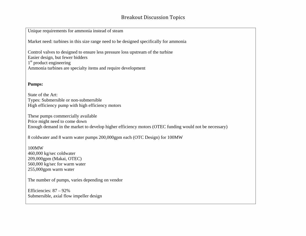
Breakout Discussion Topics
Unique requirements for ammonia instead of steam Market need: turbines in this size range need to be designed specifically for ammonia Control valves to designed to ensure less pressure loss upstream of the turbine Easier design, but fewer bidders 1st product engineering Ammonia turbines are specialty items and require development Pumps: State of the Art: Types: Submersible or non-submersible High efficiency pump with high efficiency motors These pumps commercially available Price might need to come down Enough demand in the market to develop higher efficiency motors (OTEC funding would not be necessary) 8 coldwater and 8 warm water pumps 200,000gpm each (OTC Design) for 100MW 100MW 460,000 kg/sec coldwater 209,000gpm (Makai, OTEC) 560,000 kg/sec for warm water 255,000gpm warm water The number of pumps, varies depending on vendor Efficiencies: 87 – 92% Submersible, axial flow impeller design

Breakout Discussion Topics
10MW 2 cold water pumps would be available as state of the art today Available from 2 vendors ~9month to a year lead time Working Fluid Pump (ammonia): NH3 Parameters: OTC 8 working fluid feed pumps (1operating, 1 standby) 2 per heat exchanger 8 recycle pumps Total: 16 pumps These pumps are commercially available and inexpensive Lowest cost hardware in the system Require more maintenance Limited application for hybrid cycles in offshore projects Would need to transport the water to shore (economical?) How far offshore is it? What will it cost to ship the water back to mainland? Or produce the water onshore using the power produced from OTEC A study needs to be completed to determine offshore vs. onshore water production Vacuum pump: commercially available at this scale

Breakout Discussion Topics
Closed Cycle Operating Parameters:
State – of – the Art Technologies
Turbine
100 MW (135MW) Inlet ammonia temp is 21 C = 69.8 F Outlet ammonia temp is 9.7 C = 49.46 F Pressure in: 890 kPa = 129.1 psi Pressure out: 609 kPa = 88.3psi Flow rate: 3566 kg/s Efficiency not listed (Guam OTEC Makai study) 20 MW Inlet temp: 69.6 F Pressure inlet: 127.9 psia Exit Pressure: 90.8 psia Exit temp: 50.9 F (Baseline Designs of Moored and Grazing 40-MW OTEC Pilot Plants George and Richards June 1980 JHU/ APL SR – 80-1A
Cold Water Pump
Flow rate: Operation efficiency: Motor efficiency: Head:
Warm Water Pump

Breakout Discussion Topics
Working Fluid Pump

Breakout Discussion Topics
Topic State of the Art Engineering Challenge
Processes
Fabrication
Deployment
Construction
Installation
OMR&R
Environmental Monitoring
Safe Operating Procedures

Breakout Discussion Topics
Decommissioning RISKS ASSOCIATED WITH PROCESS FAILURE
COMPONENT VIABILITY
ECONOMIC FACTORS
HURDLES/LIMITING FACTORS
DEVELOPMENT TIME FRAME

Breakout Discussion Topics
Breakout Session II: Wednesday, November 4: 10:15-12:15 1) What processes (e.g., equipment, personnel) of the technology are associated with:
i. Fabrication, deployment, construction, and installation; ii. Operation (including monitoring) and maintenance (including cleaning, repair, and replacement);
iii. Monitoring component performance; iv. Personnel safety and emergency preparedness; and v. Decommissioning?
2) What risks are associated with failure with these processes?
Notes:

Breakout Discussion Topics
Topic State-of-the-art: Engineering Challenge PROCESSES:
Fabrication Deployment Construction Installation OMR&R Environmental Monitoring Safe Operating Procedures
Decommissioning Risks Associated with Process Failure
Component Viability Economic Factors Hurdles/Limiting Factors Development Time Frame

Breakout Discussion Topics
Breakout Session III: Wednesday, November 4: 12:45-15:00 1) Are the technologies associated with this component viable? What are the economic factors associated with these technologies? What are the hurdles/limiting factors associated with these technologies? 2) What is the development time frame for the tecnologies associated with this component?

6/10/2010
1
Pumps & TurbinesTurbines
manufacturability Not difficult at 5-10 MW and larger outputs up to 100 MW. Standard manufacturing practices in existence (forging, machining & casting).
operability Fully adaptable to platform environment
reliability Most reliable component in the system. Long periods between routine inspectionsbetween routine inspections.
logistics Stock critical spares (rotors, seals, bearings, etc.) Periodic inspections opportunities during downtimes caused by other components. 18-24 month lead time to delivery.
scalability 5-10 MW Turbine (radial flow) has size limit. Larger size axial turbines, add blade length or number of blade stages to achieve greater output or efficiency.
Assumptions:-Closed cycle operating system
Pumps & TurbinesWater Pumps
manufacturability Max impeller diameter 7ft. Wide range of design base configurations available from multiple vendors.
operability Warm water pump issue with organisms.
reliability Pumps have proven high reliability. Multiple or oversize pumps to sustain operationpumps to sustain operation.
logistics Depot repair for submersible pumps; organic partial repair potential for non-submersible. 12-18 month lead time.
scalability Maximum size limit on some of these pumps for the larger plant, driving towards multiple pumps.
Assumptions:-Closed cycle operating system
Pumps & TurbinesWorking Fluid Pumps
manufacturability Wide range of design base configurations available from multiple vendors.
operability Ammonia pumps are self lubricating.
reliability Pumps have proven high reliability. Multiple pumps to sustain operationsustain operation.
logistics 12-18 month lead time. Critical spares necessary.
scalability No scaling issues. Scaling is achieved through module replication.
Assumptions:-Closed cycle operating system
DecommissioningTurbines‐• Turbines shaft/rotor‐ carbon steel or low alloy steel • Turbine blades‐ 12% chromium stainless steel or higher alloy steel • Turbine casing‐ carbon steel • Misc. parts‐ bearings (babbit) – can be re‐melted, valves and seals – stainless steel
Pumps‐• Casings – carbon steel (may have epoxy coating or other corrosion protection)• Impeller‐ stainless steel• Motor‐ combination of copper, solder, insulation material; non‐metallic material, • Shaft casing‐ carbon steel
Conclusion‐• > 85‐90% recyclable materials• Contaminants associated with decommissioning‐ oils + solvents

6/10/2010
2
Viability of technologiesAll commercially available technology that can be altered to fit these requirements.
Economic factors:• All components are technologically mature. All pumps and turbines 80‐90%
efficient.
Limiting factors:• None
Development time frame:• Required custom modifications:• 18‐24 months for turbine• 6 ‐12 months for pumps
• Dependent on size of unit.

6/10/2010
1
Pumps and Turbines
Breakout Session 1: State-of-the-Art Technologies
Assumptions:
• Closed cycle leading contender for near term commercialization
References:
G OTEC F ibilit A t• Guam OTEC Feasibility Assessment
• Baseline Designs of Moored and Grazing 40-MW OTEC Pilot Plants
• Renewable Energy From the Ocean
• OTC Study
Components Addressed:
• Turbines
• Pumps– Cold Water Pump
W W t P– Warm Water Pump
– Working Fluid Feed Pumps
– Vacuum Pump (Open/Hybrid Cycles)
Turbines
• Reviewed Operating Parameters for 30 year period and remained consistent
• Ammonia turbines are specialty items and require additional development time
• Optimization for ammonia working fluid is desirable • Radial Flow for 10MW
– 2 per plant – 7 - 8 MW gross each turbine – Commercially Available, multiple vendors
• Axial Flow for 100MW – Trade study recommended to optimize size for NH3
• For all power levels multiple turbines are required for modularity, reliability, redundancy, operation and maintenance

6/10/2010
2
Cold/Warm Water Pumps • Axial Flow impeller design
• Submersible vs. non
• High efficiency pumps with high efficiency motors
• 87-92% efficiency possible in some configurations
• Commercially available
• Multiple vendors
Working Fluid Pumps
• Feed pumps
• Recycle pumps
• One of the lowest cost items in the system
• Commercially available
• Large Design database established
Vacuum Pumps
• Needed for Hybrid Cycle
• Commercially adaptable database
• Currently used in conventional sea water l d l d f il l t f t tcooled nuclear and fossil plants for start-
up
• Trade off studies need to be performed relative to the location of water production (onshore vs. offshore)

APPENDIX E:
Platforms

Breakout Discussion Topics
Breakout Session I: GROUP F Tuesday, November 3: 13:00-15:30 What are the state-of-the-art technologies for the technical component?
Platform
-Aimed towards offshore platforms for this workshop -Differences between open and closed cycle systems
-Closed cycle: The working fluid (typically ammonia) is in a closed system and is evaporated/condensed using heat exchangers. The evaporated working fluid powers the turbine generator.
-Pumping around 10,000 gallons seawater/second/MWe -Ammonia (working fluid) will make up about 30% of the payload -Open cycle: The warm seawater is the working fluid and is flash evaporated using a vacuum. Steam generated by the vacuum powers the turbine generator. -Must pump much more water to generate similar amounts of electricity as closed cycle systems -Location, size, and volume of the system components on the platform are the driving issues of platform design -The design of the platform depends on the entire system -There most likely will not be one standard design for OTEC platforms due to location, ocean conditions, size of the OTEC system, what kind of system (open vs. closed), etc. -Options for platform shapes are: -Semi-submersible platform -Spar -Ship shape

Breakout Discussion Topics
TYPE MOTION/
SURVIVABILITY RISKARRANGEMENT
DIFFICULTY COST TECHNICAL
MATURITY SEMI
SUBMERSIBLE SMALL MEDIUM MEDIUM HIGH
SPAR
SMALL HIGH MEDIUM-HIGH MEDIUM
SHIP SHAPE
MEDIUM LOW LOW HIGH
-Need to consider transportation of the structure -Need to consider deck installation -Platform TRL = 9 -Mission Condition TRL = ? (hasn’t been done before on the scale we’re interested in) -For similar situations (floating platforms/oil rigs) = 9 -Offshore oil rig requirements far exceed the requirements for OTEC

Breakout Discussion Topics

Breakout Discussion Topics
Breakout Session II: Wednesday, November 4: 10:15-12:15 1) What processes (e.g., equipment, personnel) of the technology are associated with:
i. Fabrication, deployment, construction, and installation; ii. Operation (including monitoring) and maintenance (including cleaning, repair, and replacement);
iii. Monitoring component performance; iv. Personnel safety and emergency preparedness; and v. Decommissioning?
2) What risks are associated with failure with these processes?
-Relocatability is an issue depending on the type of platform (difficult with a spar platform) -Strive for maximum versatility with minimum costs -Standardize OTEC design so that it is more or less repeatable -Make Semi-Submersible platform design a baseline

Breakout Discussion Topics
Topic Engineering or Operating Challenges for OTEC (failure risks) PROCESSES:
Fabrication State-of-the-art Deployment State-of-the-art Construction N/A Installation (integration and commissioning)
-Deck equipment modules sized for lifting capability at integration site -Floating draft less than depth at integration site
OMR&R State-of-the-art Monitoring State-of-the-art Safe Operating Procedures
State-of-the-art
Decommissioning State-of-the-art Component Viability Little or no risk of component failure under standard operating conditions Economic Factors Hurdles/Limiting Factors Development Time Frame

Breakout Discussion Topics
Topic: Semi-submersible Manufacturability Operability Reliability Logistics Scalability PROCESSES:
Fabrication Semi-Submersible: Standard offshore
rig fabrication Spar: Fewer
qualified manufacturing
facilities Monohull:
Acceptable FPSO Construction
--
High Less than established
offshore industry
No issues
Deployment N/A N/A High Standard heavy-lift
ships sufficient up
to 20,000 tons Spar: ~165 m
length limitation
Adequate for 20,000 ton total
weight (hull and equipment)
Construction (Assumed same as fabrication)
Spar: Outfitting with OTEC equip is more complicated Monohull: Ship is more amenable to
installation of internal OTEC
equip
-- -- -- --
Installation (Integration Quayside deck Local lift High (if the Wet-tow to Standard oil rig

Breakout Discussion Topics
and commissioning) commissioning Spar: Requires
deepwater for deck installation and
heavy lift or float over
capacity for integration may be an issue (eg.
pacific islands)
equipment is available)
final site (short
distance) or dry-tow (long
distance)
techniques
OMR&R Routine/ Standard
maintenance (simpler than typical oil rig)
Spar: More Difficult to
access Monohull:
Greater response to sea states
Close to shore
Monitoring Performance monitoring
Monohull: Instrumentation
advised to monitor fatigue
Safe Operating Procedures
Meet regulatory and company HSE
operating requirements
High
Decommissioning In accordance with current practices
Spar: Harder
N/A High Transporting to desired
location for disposal
N/A
Relocation NA Consistent High Requires new NA

Breakout Discussion Topics
with Normal Practices
Spar: Difficult, may
not be cost effective
moorings; Spar:
Extensive disassembly +
reassembly
Manufacturability Operability Reliability Logistics Scalability *Based on Semi-Submersible platform design COST: -Consistent with normal marine practice -Bulk steel plus labor -Making the hull the simplest it can be (minimal equipment within) will keep costs down -Design to manufacture -work with the shipyard -FEED design (front-end engineering design) -Suppose a 100 Million dollar project, steel would be about 2,000 $/ton (for just materials, no labor) -Standardization of design will significantly lower costs from the first to the second design -learning curve and non-recurring costs -The pound per facility for OTEC will be less than the pound per facility for other platform type rigs (oil industry) -Since OTEC is a fundamentally different system than normal oil rig platforms, can we go about designing and building a platform a different way to reduce costs significantly? 4 Key Factors: -Standardization -Mass Production -Progressive Innovation -Versatility Standards for offshore oil requirements for semisubs and spars currently exist; standards for OTEC would need to be developed
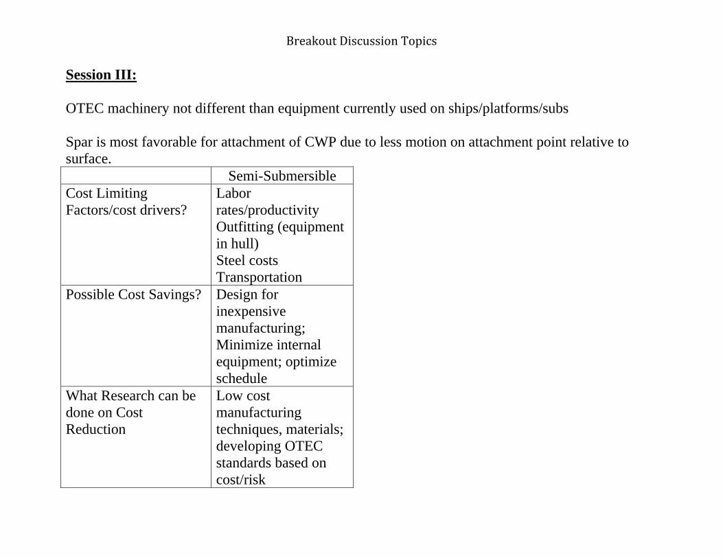
Breakout Discussion Topics
Session III: OTEC machinery not different than equipment currently used on ships/platforms/subs Spar is most favorable for attachment of CWP due to less motion on attachment point relative to surface. Semi-Submersible Cost Limiting Factors/cost drivers?
Labor rates/productivity Outfitting (equipment in hull) Steel costs Transportation
Possible Cost Savings? Design for inexpensive manufacturing; Minimize internal equipment; optimize schedule
What Research can be done on Cost Reduction
Low cost manufacturing techniques, materials; developing OTEC standards based on cost/risk

Breakout Discussion Topics
Are Technologies viable?
Yes
What are the associated economic factors?
What are the hurdles/limitations?
What is the development Time?

Breakout Discussion Topics

Breakout Discussion Topics
Breakout Session III: Wednesday, November 4: 12:45-15:00 1) Are the technologies associated with this component viable? What are the economic factors associated with these technologies? What are the hurdles/limiting factors associated with these technologies? 2) What is the development time frame for the tecnologies associated with this component?

Changes In Platform Technology Si 1980Since 1980
• 19801 R i d ff h OTEC
• Today1 Fl ti d ti l tf1. Required offshore OTEC
depth of 3000ft is considered technically challenging for offshore oil industry
2 Floating production systems
1. Floating production platforms at 3000ft considered routine from a technical standpoint
2. There are about 200 floating production systems2. Floating production systems
were at infant technology3. Limited software was
available and data was not validated
production systems3. Computer software and
experimental facilities for design are in use and have been validatedvalidated
4. Limited ability to predict impact of extreme weather
5. Platforms were designed to very conservative standards
been validated4. Meteorological/
oceanographic data gathering capability is more sophisticatedvery conservative standards
due to uncertainties in extreme storm conditions and calculation accuracy
sophisticated5. Improved tools and
oceanographic data allows design of more cost effective platformsp

6/10/2010
1
Platform Group
Day II Discussion
Challenges and Risks
Topic Engineering or Operating Challenges for OTEC (failure risks)
PROCESSES:
Fabrication State-of-the-art
Deployment State-of-the-art
Construction N/AConstruction N/A
Installation (integration and commissioning)
-Deck equipment modules sized for lifting capability at integration site
-Floating draft less than depth at integration site
OMR&R State-of-the-art
Monitoring State-of-the-art
Safe Operating Procedures
State-of-the-art
Decommissioning State-of-the-art
Component Viability Little or no risk of component failure under standard operating conditions
ProcessesTopic: Semi-submersible Manufacturability Operabil
ityReliability Logistics Scalability
PROCESSES:
Fabrication Semi-Submersible: Standard offshore rig fabricationSpar: Fewer qualified manufacturing facilitiesM h ll A t bl
-- High Less than established
offshore industry
No issues
Monohull: Acceptable FPSO Construction
Deployment N/A N/A High Standard heavy-lift ships sufficient up to
20,000 tonsSpar: ~165 m
length limitation
Adequate for 20,000 ton total weight (hull and
equipment)
Construction (Assumed same as fabrication)
Spar: Outfitting with OTEC equip is more complicated
Monohull: Ship is more amenable to installation of
internal OTEC equip
-- -- -- --
ProcessesTopic: Semi-submersible Manufacturability Operability Reliability Logistics Scalability
PROCESSES:
Installation (Integration and commissioning)
Quayside deck commissioningSpar: Requires
deepwater for deck installation and heavy
lift fl t
Local lift capacity for integration may be an issue (eg. pacific islands)
High (if the equipment is
available)
Wet-tow to final site (short
distance) or dry-tow (long
distance)
Standard oil rig techniques
lift or float over
OMR&R Routine/ Standard
maintenance (simpler than typical oil rig)
Spar: More Difficult to
accessMonohull:
Greater response to sea
states
Close to shore
Monitoring Performance monitoring
Monohull: Instrumentation
advised to monitor fatigue
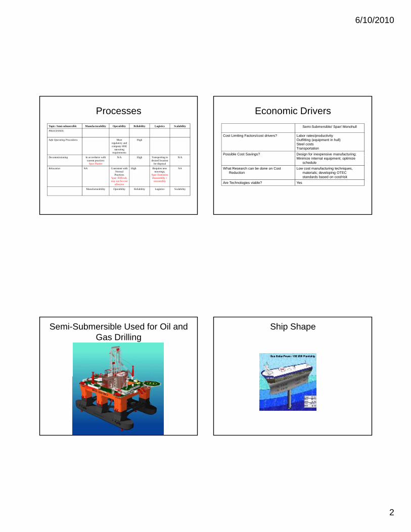
6/10/2010
2
ProcessesTopic: Semi-submersible Manufacturability Operability Reliability Logistics Scalability
PROCESSES:
Safe Operating Procedures Meet regulatory and company HSE
operating requirements
High
Decommissioning In accordance with current practices
Spar: Harder
N/A High Transporting to desired location
for disposal
N/A
Relocation NA Consistent with Normal
PracticesSpar: Difficult, may not be cost
effective
High Requires new moorings;
Spar: Extensive disassembly +
reassembly
NA
Manufacturability Operability Reliability Logistics Scalability
Economic Drivers
Semi-Submersible/ Spar/ Monohull
Cost Limiting Factors/cost drivers? Labor rates/productivity Outfitting (equipment in hull)Steel costsTransportation
Possible Cost Savings? Design for inexpensive manufacturing;Possible Cost Savings? Design for inexpensive manufacturing;Minimize internal equipment; optimize
schedule
What Research can be done on Cost Reduction
Low cost manufacturing techniques, materials; developing OTEC standards based on cost/risk
Are Technologies viable? Yes
Semi-Submersible Used for Oil and Gas Drilling
Ship Shape

6/10/2010
3
“Red Hawk” Spar Platform

APPENDIX E:
Power Cable

Breakout Discussion Topics
Breakout Session I: Tuesday, November 3: 13:00-15:30 What are the state-of-the-art technologies for the technical component?
Ocean cable technology known, manufactures have the necessary cables Armoring the cable (steel) – trench closer to shore, water jets, plowing directional drilling, shore landings Pressure is a problem b/c of the depth AC cable within 20 miles – copper conductor, polyethylene insulation Cables must survive for 30 plus years Termination technology on platform side is a challenge Problem with motion of suspended cable from bottom of the ocean to the platform, fatigue, bending stress/strain Need modeling for connection of the cable and for the dynamics of the cable Cable length > 20 Km solution is DC Potential corrosion issue with steel armor on cable Larger availability in lower voltage Cables available up to 500 kV Splicing technology is known
Companies Available today
Subocean JDR Cable Systems Seabed Power ABB Nexans Sumitomo Siemens South bay General Cables

Breakout Discussion Topics
Falmat Parker Scancorp Prysmian Cables and Systems: long cable up to 500 kV (NY, NJ)

Breakout Discussion Topics
Mechanical

Breakout Discussion Topics
Breakout Session II: Wednesday, November 4: 10:15-12:15 1) What processes (e.g., equipment, personnel) of the technology are associated with:
i. Fabrication, deployment, construction, and installation; ii. Operation (including monitoring) and maintenance (including cleaning, repair, and replacement);
iii. Monitoring component performance; iv. Personnel safety and emergency preparedness; and v. Decommissioning?
2) What risks are associated with failure with these processes?
Notes:

Breakout Discussion Topics
Topic State-of-the-art: Engineering Challenge PROCESSES:
Fabrication Deployment Construction Installation OMR&R Environmental Monitoring Safe Operating Procedures
Decommissioning Risks Associated with Process Failure
Component Viability Economic Factors Hurdles/Limiting Factors Development Time Frame

Breakout Discussion Topics
Breakout Session III: Wednesday, November 4: 12:45-15:00 1) Are the technologies associated with this component viable? What are the economic factors associated with these technologies? What are the hurdles/limiting factors associated with these technologies? 2) What is the development time frame for the tecnologies associated with this component?

Day 3 – GROUP G What changes have occurred in materials, designs, practices, fabrication, manufacturing, and technology between 1980 and today to make OTEC feasible to pursue on a commercial scale?
Today: 10 sea crossing AC cables from 90 kV-to500 kV 20 DC cables up to 500 kV Majority have occurred in last 10 years Availability of remote resources and interconnection of grids
o US: east coast NY/NJ o From Canada to NJ
Dynamics cables: technology driven by offshore wind farming o Off shore oil drilling o Common connection by 13.6kV up to 50 kV o Connection at platform are standard and routine, sock rigid connection run
through tube, secured at top o Length, width, diameter are function of cable o Swivel joint done on top side like fixed connection
Offshore wind floating platforms o Individual cables to shore
R and D
High power dynamic cable greater than 30 MW

State of the Art
•Available TechnologiesC d d t d d f bl t ti–Codes and standards for cable construction
•IEEE and IEC•ABS DNV and APIABS, DNV, and API
–Many manufactures•Larger availability with lower voltage
–Armoring: Steel–In water cable transition (platform to ocean b tt )bottom)
•Can be computer modeled•Software readily availableSoftware readily available

State of the Art cont.
• Cable Voltage rating up to 500 kV– ACAC
• Single Phase is 69 kV and up• Three phase cable below 69 kV• AC within 20 miles of shore
– DC• Available up to 400 kV today• Has to be converted on both ends
• Standard Splicing Technology• Typ. done in factory
• Standard Shore Landing• Standard Shore Landing• Directional drilling• Trenching
Proven Durability• Proven Durability• Corrosion

Manufacturers • JDR Cable Systems• ABBABB• Nexans• Sumitomo• Siemens• South bay• General Cables• Falmat• Parker Scancorp

Challenges Specific to OTECg p
• Applicable standards specifically for OTECApplicable standards specifically for OTEC
• Hydrostatic pressure
• Large vertical riser cableLarge vertical riser cable
• Mechanical termination technology at the platformplatform
• Modeling– Connection of cableConnection of cable
– Mechanical dynamics of the cable
• Cable Installation

6/10/2010
1
POWER CABLE
POWER CABLE – Day 2
DAY 2 – Breakouts II and III
Assumptions• Offshore
– Less than 20 miles– Water depth 1,200 m or less
• Floating • Moored
– Cable and termination design depends on dynamics and azimuth constraints on platform and mooring configuration
– Potential requirement to disconnect for weather drives complexityP i ll R l bl ( l f )
POWER CABLE – Day 2
• Potentially Relocatable (platform)– Not applicable for cable– Interconnect design depends on location
• 5-10 MW to commercial scale (100 MW)– Three phase AC cable, up to 10 MW– Three single phase AC cables, 100 MW– Cable includes power and communication controls– Cable includes own diagnostic system, fiber optic for temperature
sensing
Breakout II – Manufacturability• Fabrication
– Cable: Commercially available– Termination: Custom design b/c of motion
• Fatigue testing required
• Deployment– Difficult but well understood
POWER CABLE – Day 2
• Difficult on steep shelf– Issue with depth b/c of limited experience– Handling the weight of cable– Cable site survey and route planning necessary
• Installation– Need sufficient space for platform substation– AC equipment requires less space
Breakout II – Operability• Operation
– Fully automated and controlled from shore– Enclosed environmentally controlled substation
• Keep out salt water and humidity • Dry type oil free transformer
• Maintenance Cleaning
POWER CABLE – Day 2
– Cleaning• Periodic marine growth (diver), and full cable inspection• Annual maintenance of substation
– Cable Repair• Standard practice in shallow water• More difficult in power cables in deep water• Splice requires mobilization of ship
– Replacement• Leave adequate time to order new cable• Depends on location of fault
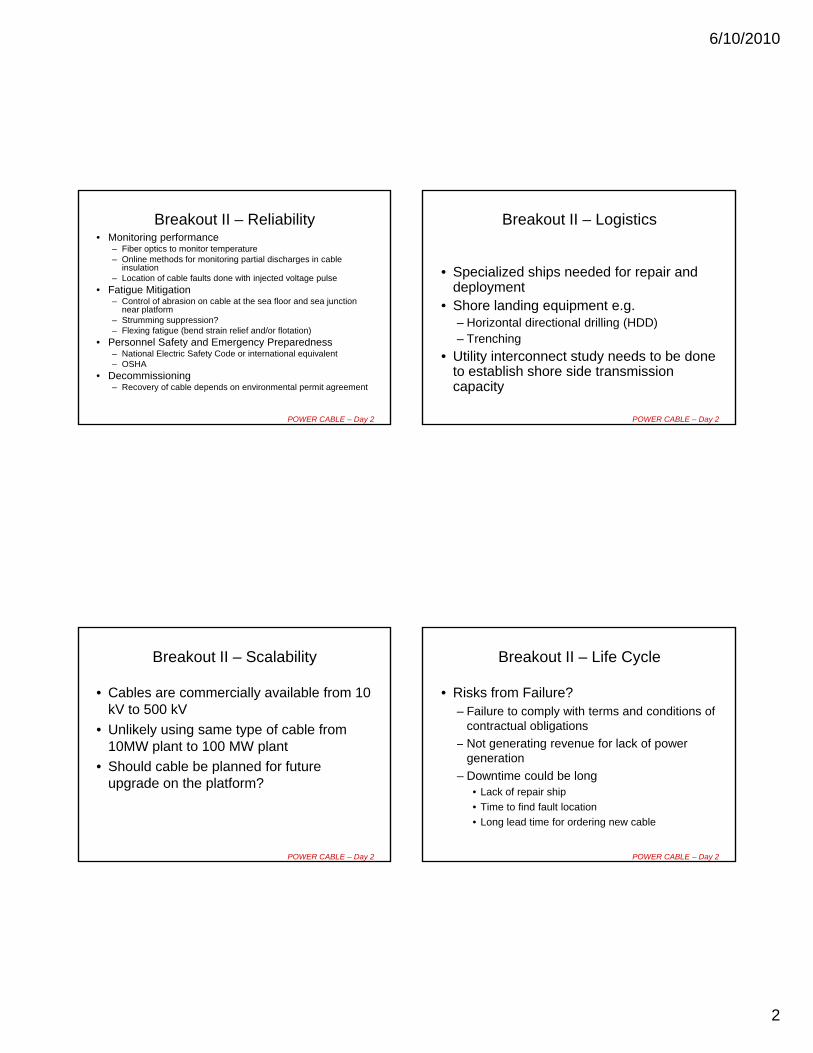
6/10/2010
2
Breakout II – Reliability• Monitoring performance
– Fiber optics to monitor temperature– Online methods for monitoring partial discharges in cable
insulation– Location of cable faults done with injected voltage pulse
• Fatigue Mitigation– Control of abrasion on cable at the sea floor and sea junction
l tf
POWER CABLE – Day 2
near platform– Strumming suppression?– Flexing fatigue (bend strain relief and/or flotation)
• Personnel Safety and Emergency Preparedness– National Electric Safety Code or international equivalent– OSHA
• Decommissioning– Recovery of cable depends on environmental permit agreement
Breakout II – Logistics
• Specialized ships needed for repair and deployment
• Shore landing equipment e g
POWER CABLE – Day 2
Shore landing equipment e.g. – Horizontal directional drilling (HDD)– Trenching
• Utility interconnect study needs to be done to establish shore side transmission capacity
Breakout II – Scalability
• Cables are commercially available from 10 kV to 500 kV
• Unlikely using same type of cable from 10MW plant to 100 MW plant
POWER CABLE – Day 2
10MW plant to 100 MW plant
• Should cable be planned for future upgrade on the platform?
Breakout II – Life Cycle
• Risks from Failure?– Failure to comply with terms and conditions of
contractual obligations
– Not generating revenue for lack of power
POWER CABLE – Day 2
Not generating revenue for lack of power generation
– Downtime could be long• Lack of repair ship
• Time to find fault location
• Long lead time for ordering new cable

6/10/2010
3
Breakout II – Life Cycle
• Cost limiting factors?– Material costs such as copper and steel
– Shortage of cable manufacturing capability
– Limited number of cable laying ships
POWER CABLE – Day 2
– Weather and location
– Scheduling of ships
– Survivability mitigation (burying or trenching, micro tunneling)
Breakout II – Life Cycle cont.
• Cost savings?– Tagging on to existing orders
– Location closer to shore landing means less cable
– Distance to shore from interconnect should be shorter
POWER CABLE – Day 2
– Overhead line from shore to utility connection
• Research for cost reduction?– Reducing weight with use of different materials
– Flexible connection and termination to platform
– Fatigue testing
Breakout III • Technologies viable?
– Cable • TRL-8/9
• MRL-9/10
– Cable connection at platform? (
POWER CABLE – Day 2
• TRL and MRL-5? Depending on requirements (like mooring, platform dynamics, quick disconnect) and needs further study
• Custom solution
• Site specific
• Economic factors?– Exchange rate
– Cost of materials
Breakout III cont.
• Hurdles or limiting factors?– Cable route
– Limited supplier of armored cable
Riser Cable
POWER CABLE – Day 2
– Riser Cable
– Flexible connection to platform
– Availability of ship

6/10/2010
4
Breakout III
• Development time frame?– 2-3 years
• Driven by OTEC system level modeling, simulation and design
POWER CABLE – Day 2
g
– Cable connection to platform
– Integrated platform mooring cable simulation
– Normal design and development time frame for pilot plant

Appendix F
Powerpoint Presentations

6/10/2010
1
WelcomeWelcome
Logistics• Fire Exits
• Restrooms on this level
• Map of conference center in packets – location of breakout rooms
• Dining – breakfasts & snacks (outside meeting rooms)
• Lunch:
− Hot/Cold Buffet
Dining Room (on this level)− Dining Room (on this level)
− Reserved seating
• Evening Dinner:
− Shuttle – pick up outside New England Center at 6:30 pm
− Mahalos Catering at The Pearl in downtown Portsmouth
− Cash bar available (beer and wine)
− If you have any questions – check with staff at registration table
Key CRRC Staff
• Nancy Kinner – UNH Co‐Director
• Kathy Mandsager – Program Coordinator
• Joseph Cunningham – Research EngineerJoseph Cunningham Research Engineer
• Zachary Magdol – Engineer
Center Creation
• NOAA’s Office of Response and Restoration (ORR)/UNH spill partnership in 2004
• Co‐Directors:
− UNH – Nancy Kinner
− NOAA – Amy Merten− NOAA – Amy Merten
• Funding for oil spill research decreasing
− Government
− Private sector
• Many research needs exist regarding spill response, recovery and restoration

6/10/2010
2
Overall Mission
• Develop new approaches to response and restoration through research/synthesis of information
• Serve as a resource for ORR, NOAA and other ,agencies
• Serve as a hub for spill research, development and technical transfer for ALL stakeholders
− Spill community (U.S and internationally)
Specific Center Missions
• Conduct and oversee basic and applied research and outreach on spill response and restoration
• Transform research results into practice
• Encourage strategic partnerships to achieve mission
C d h i d d• Conduct outreach to improve preparedness and response
• Create an educational program for new approaches to spill response and restoration− Educate/train students who will pursue careers in spill response and restoration
− Internships with agencies, laboratories
Outreach Efforts
• Workshops on hot topics to identify research priorities and partners– Dispersed Oil: Efficacy and Effects
– Submerged Oil: State of the Practice
– Human Dimensions of Spills
– Dispersed Oil Research Forum
– Integrated Modeling
– PAH Toxicity
– Environmental Response Management Application (ERMA™)
– Environmental Response Data Standards
– HEA Metrics Workshop
– Opening the Arctic Seas: Envisioning Disasters & Framing Solutions
Background/ Goals/OutcomesGoals/Outcomes

6/10/2010
3
CRRC/OCRM Partnership
• NOAA’s Office of Ocean and Coastal Resource Management (OCRM) licensing of OTEC
• OCRM Director David Kennedy on CRRC Advisory BoardAdvisory Board
• OCRM Senior Policy Analyst David Kaiser affiliated with CRRC at UNH
• CRRC experience hosting workshops
OTEC Workshop
• CRRC hosting two OTEC workshops for OCRM
– November, 2009: Technical Aspects
– 2010: Environmental Impacts and Risks
• Format: Plenary Sessions and Breakout GroupsFormat: Plenary Sessions and Breakout Groups
• Participants representing a spectrum of industry, public sector, academia, and NGOs
– OTEC experts
– Related experts
• e.g., platforms, power cable, mooring
Key Concept
• Bring diverse expertise and perspectives to the table
• Dialogue on:
– Where we are?
– Where do we want to be?
– How do we get there?
Overall Goal
To Understand Technical Readiness of Commercial Scale OTEC System

6/10/2010
4
Specific Foci
• State‐of‐the‐art of OTEC Technology
• Technical feasibility
• Time frame for commercial development
Technical Components to be Discussed(Breakout Groups)
• Cold Water Pipe
• Heat Exchangers
• Platform
• Platform Mooring
• Platform/Pipe Interface
• Pumps and Turbines
• Power Cable
Plenary Panel Discussions
• Cycle and Auxiliary Uses
• OTEC as a System
AgendaTuesday AM
09:20 Background & Workshop Goals/Outcomes Nancy Kinner09:30 OTEC Timeline & Participant Introductions Iris Ioffreda, Facilitator10:30 Break10:45 Plenary Session: Setting the Stage
A. Cold Water Pipe Alan MillerB. Heat Exchangers Avram Bar‐CohenC. Platform Mooring Frederick “Rick” DriscollD. Platform/Pipe Interface Patrick GrandelliE. Pumps & Turbines Peter PandolfiniF. Platforms Edward HortonG. Power Cable Steiner DaleH. Cycle/Auxiliary Uses C.B. PanchalI. Overall System & Program Luis Vega
11:45 Workshop Structure & Logistics Iris Ioffreda

6/10/2010
5
AgendaTuesday PM
13:00 Breakout Session I Breakout Discussion Groups
15:30 Plenary Session I: Group Reports (10 minutes each)
17:00 Adjourn
18:30 Shuttle to Dinner Portsmouth
AgendaWednesday AM
09:00 Overview and Review/Recalibrate: Iris Ioffreda
09:15 Panel Discussion: Cycle and Auxiliary Uses: Today and the Future
10:15 Breakout Session II
12:15 Lunch
AgendaWednesday PM
12:45 Breakout Session III Breakout Discussion Groups
15:00 Plenary Session: Group Reports (10 minutes each)
17:00 Adjourn (Dinner on your own)
AgendaThursday
09:00 Overview/ReviewIris Ioffreda
09:15 Panel Discussion on OTEC as a System
10:30 Break
10:45 Discussion of OTEC as a System10:45 Discussion of OTEC as a System
12:00 Lunch
13:00 Plenary Session: Synthesis and Next Steps: Iris Ioffreda
14:30 Closing Remarks: Iris Ioffreda & Organizing Committee
15:30 Adjourn

6/10/2010
6
Breakout Questions for Each Component
Session I:
• What are the state‐of‐the‐art technologies for the technical component?
Breakout Questions for Each Component
Session II:
• What processes (e.g., equipment, personnel) of the technology are associated with:
• fabrication, deployment, construction, and installation;
• operation and maintenance (including cleaning repair and• operation and maintenance (including cleaning, repair, and replacement);
• monitoring component performance;
• personnel safety and emergency preparedness; and
• decommissioning?
• What risks are associated with failure with these processes?
Breakout Questions for Each Component
Session III:• Are the technologies associated with this component
viable? What are the economic factors associated with these technologies? What are the hurdles/limiting factors
i t d ith th t h l i ?associated with these technologies?
• What is the development time frame for the technologies associated with this component?
Panel Discussion Questions:OTEC as a System
• What are the performance metrics that must be demonstrated prior to commercial development? What is the development time frame (e.g., today, 1‐2 yr, 5‐10 yr) for a commercial OTEC system?
• What are the potential failures that could lead to theWhat are the potential failures that could lead to the shutdown of an OTEC system?
• What processes/diagnostics are needed to detect, monitor and reduce these risks?
• What are the flexibilities in the OTEC system’s components that could minimize environmental impacts?

6/10/2010
7
Workshop Outcomes
• Report compiling information gathered at workshops (NOT recommendations)
• Report Contents:– Introduction– Workshop organization and structurep g– Information gathered
• By component• As system
– Synthesis of workshop results– Possible research topics– Appendices – (e.g., participants, slides, relevent references)
CRRC’s Role as Workshop Host
• CRRC is a Neutral Party– No oil or OTEC in NH waters
• Expertise ‐ engineering and scientific based discussion
• Academy is safe place to have frank and open discussion
• Academia approach garners public trust– Peer review approach
• CRRC brings all parties to table
Coastal Response Research Center
www.crrc.unh.edu
Participant Introductions
• Name
• Affiliation
• Technical Expertise

6/10/2010
8
Workshop pStructure
Intended Outcomes
To understand technical readiness of commercial scale OTEC system
This Workshop is NOT:
• A decision making meeting• Looking to define one “best” technology• Asking for disclosure of proprietary information or design specsF d i l i• Focused on environmental impacts
• Focused on regulatory challenges• About the process to get a license for commercial OTEC
• It IS focused on technical, engineering issues!
Workshop Structure
• Mostly in small groups. Three breakout sessions per topic. Reports to large group on Monday and Tuesday afternoons.
• Small group facilitators will manage the discussion and help the group develop report outs.
• Each small group has an assigned note‐taker.
S i th ll ill f ti• Success in the small groups will come from active participation by all, and allowing all to have a voice.
• Issues that are relevant but not within scope of this workshop will be captured on a “Parking Lot.”
• Nancy Kinner and Iris Ioffreda will be floaters.

6/10/2010
9
What Do You See?What Do You See?
Your Role
•• What will I take away?What will I take away?
•• What will I contribute?What will I contribute?
•• What do I need to and not do toWhat do I need to and not do toWhat do I need to and not do to What do I need to and not do to make both those things happen?make both those things happen?

6/10/2010
10
Ground Rules
• Be fully present (which includes turn off ringtones for cell phones and blackberries)
• Honor time schedules
• Speak openly and honestly and only for p p y y yyourself
• Allow everyone an opportunity to express their views
• Ask questions and listen for understanding

This Workshop is NOT:This Workshop is NOT:
• A decision making meetingg g• Looking to define one “best” technology• Asking for disclosure of proprietary information or design specs
• Focused on environmental impactsF d l t h ll• Focused on regulatory challenges
• About the process to get a license for commercial OTECOTEC
• It IS focused on technical, engineering issues!, g g

6/10/2010
1
Workshop pStructure
Intended Outcomes
To understand technical readiness of commercial scale OTEC system
This Workshop is NOT:
• A decision making meeting• Looking to define one “best” technology• Asking for disclosure of proprietary information or design specsF d i l i• Focused on environmental impacts
• Focused on regulatory challenges• About the process to get a license for commercial OTEC
• It IS focused on technical, engineering issues!
Workshop Structure
• Mostly in small groups. Three breakout sessions per topic. Reports to large group on Monday and Tuesday afternoons.
• Small group facilitators will manage the discussion and help the group develop report outs.
• Each small group has an assigned note‐taker.
S i th ll ill f ti• Success in the small groups will come from active participation by all, and allowing all to have a voice.
• Issues that are relevant but not within scope of this workshop will be captured on a “Parking Lot.”
• Nancy Kinner and Iris Ioffreda will be floaters.

6/10/2010
2
What Do You See?What Do You See?
Your Role
•• What will I take away?What will I take away?
•• What will I contribute?What will I contribute?
•• What do I need to and not do toWhat do I need to and not do toWhat do I need to and not do to What do I need to and not do to make both those things happen?make both those things happen?

6/10/2010
3
Ground Rules
• Be fully present (which includes turn off ringtones for cell phones and blackberries)
• Honor time schedules
• Speak openly and honestly and only for p p y y yyourself
• Allow everyone an opportunity to express their views
• Ask questions and listen for understanding

6/10/2010
1
NOAA OTEC WorkshopNov 3 5 2009
Luis A. Vega, Ph.D.National Marine Renewable Energy Center
at University of Hawai’i
Nov 3-5, 2009University of New Hampshire
1
Workshop Objectives
• Are commercialization challenges: (i) Technical, (ii) Engineering (ii) Engineering, (iii) Development costs?
• OTEC Development Roadmap
2
USA OTEC: Development Schedule(Assumption)
USA OTEC DEVELOPMENT YEARS 1 to 5 6 to 10 11 to 15 16 to 20 21 to 25 26 to
Pre-Commercial Plant (> 5 MW) Ops
Electricity (Desal Water) Plants in Hawaii and USA Territories: ~ 20 x 100 MW Plants
Prelim Design Ops Ops
NH3/H2 Plantships Supplying all States
Prelim Design Ops
3
OTEC: The Challenge• Major Challenge is not technical but
rather financing of a capital intensive technology without an operational record;
• If plant > 50 MW, cost of electricity ($/kWh) would be cost competitive; ($ ) p How do you get more than ¾ Billion Dollars for a 100 MW plant without a “track record” and without invoking national security, global warming, environmental credits, etc.?
• Without operational records from a pre-commercial plant ( 5 MW) financing of commercial sized plants (> 50 MW) is highly doubtful;
4

6/10/2010
2
OTEC Pre-Commercial Plant• Federal funding required for pre-commercial
plant ( $120M to $150M);
• Pre-Commercial Plant would take 5-years from the go-ahead to deliver electricity to the grid;g ;
• Pre-Commercial Plant must operate for at least one year before finalizing engineering and environmental-impact mitigation design aspects of the commercial size plant;
• The Commercial Plant would take another 4 to 5-years to deliver electricity to the grid;
5
Economics Summary
Because OTEC is capital intensiveelectricity cost-competitiveness if electricity cost competitiveness if Size > 50 MW & > 15-year Life-Cycle.
6
y = 53185x-0.364
30,000
40,000
50,000
60,000
Cos
t, $
/kW
1st Plant and 10th PlantCapital Cost Estimates
y = 36525x-0.365
0
10,000
20,000
30,000
0 5 10 15 20 25 30 35 40 45 50 55 60 65 70 75 80 85 90 95 100Inst
alled
Capita
l
Nominal Plant Size, (MW-net)7
60
70
80
90
100
/kW
h
Cost of Electricity Production for 1st Plant and 10th Plant[ COE = CC + OMR&R ]
Loan: 8%/15-Years 3% Inflation2006 Capital Cost Estimates
1st Plant
0
10
20
30
40
50
1.35 5 10 50 100
COE,
c/
Nominal Size, MW-net
10th Plant
8

6/10/2010
3
50
60
70
80
/kW
h
OTEC Cost of Electricity Production as a
Function of Loan Term
8% 15-Years (Bank Loan)
4.2%/20-Years (State Bonds)
For 10th Plant
0
10
20
30
40
1.35 5 10 50 100
COE,
c/
Nominal Size, MW-net
9
OTEC Plant ScheduleOTEC PLANT SCHEDULE Year 1 Year 2 Year 3 Year 4 Year 5
1.0 MANAGEMENT
2.0 ENGINEERING DESIGN/PERMITS
3 0 ACQUISITION & CONSTRUCTION3.0 ACQUISITION & CONSTRUCTION Long-Lead Items
4.0 DEPLOYMENT
5.0 STARTUP & COMMISSIONING
6.0 OPERATIONS
10
OTEC Plant Schedule• Detailed-Engineering-Design one-year;
Permits two-years;• Major components are long-lead-items,
requiring 12 to 24+ months for delivery, q g f y,and are available from established industry;
• As much as 5-years after-receipt-of-order (ARO) is required before delivering electricity to grid.
11
Workshop Objectives
• Are commercialization challenges: (i) Technical,
(ii) Engineering(ii) Engineering,
(iii) Development costs
• OTEC Development Roadmap (see p. 3)
12

1
Navy Ocean Energy Program
Bill TaylerDirector, Energy Development
NAVFACENGCOM, Public Works
Ocean Thermal Energy Conversion (OTEC) Technology WorkshopUniversity of New Hampshire, Durham NH
November 3, 2009
80% of world’s fuel travels by ocean
90% of world’s trade travels through choke points
Navy’s fuel cost in 2007 was $1.2B, in 2008 it was $5.1B
Things that Keep Us Up at Night
page number 2
U.S. imports 57% of energy needs
Piracy adds $1M to shipping costs/trip
Cost to refill a DDG-51: $1.8M in 2008, $643K in 2009
FBCF $400/gal
Impact to military readiness
The lifecycle energy cost of platforms, weapons systems, and buildings, the fully-burdened cost of fuel in powering these, and contractor energy footprint will be mandatory evaluation factors used when awarding contracts.
The Navy will demonstrate a Green strike group of nuclear vessels and ships using biofuel in local operations by 2012. By 2016, the Navy will sail a “Great Green Fleet”
Recent Guidance from Administration
On October 14, 2009, the Secretary of the Navy established five Department of the Navy (DoN) Energy Targets:
page number 3
the Navy will sail a Great Green Fleet composed of nuclear ships, surface combatants with hybrid electric power systems using biofuel, and aircraft flying only on biofuels.
By 2015, the Department of the Navy (DoN) will reduce petroleum use in the commercial fleet of 50,000 vehicles by 50 percent by phasing in a composite fleet of flex fuel, hybrid electric, and neighborhood electric vehicles.
By 2020, at least half of the DoN’s shore-based energy requirements will come from alternative sources.
By 2020, half of total DoN energy consumption will come from alternative sources.
F-18 Green Hornet
What do we want?/ What do we bring to the table?
What do we want? “Operational Independence” Long term goal: For island locations obtain reliable & affordable
power, water and cooling from ocean resources – power purchase agreement
Short term goal: Partner with industry to expedite commercialization of ocean power with emphasis on OTEC
page number 4
What do we bring? funding
sponsor for SBIR and Congressional Adds
long term contracts (stability)
land, infrastructure support, security
we pay our bills favorable financing terms
assistance expediting permitting
with DOE & NOAA, help to bring industry together

2
OTEC Opportunities
Navy first looking at Diego Garcia, Hawaii & Guam
page number 5Courtesy: NASA Jet Propulsion Laboratory
Hawaii
Diego Garcia
Guam
Kwajalein
Island RequirementsIsland Requirements
Reliable electric power supply to meet mission (no grid for reliability)
Eliminate vulnerable fuel oil supply Adequate, potable water supply Refrigeration/cooling Reduce/eliminate environmental impacts
page number 6
OTEC offers hope as potential long term baseload technology for island locations, with further benefits from renewable fuel and potable water generation
Problem- expanding OTEC to required scale and competitive pricing requires technological and commercial advances
For OTEC to assist in meeting Navy goals, OTEC commercialization needs to speed up
Role of US Navy in supporting OTEC
page number 7
Navy plans to partner with DOE, NOAA and industry to advance the technology Navy has multiple OTEC and other
ocean energy R&D investments designed to commercialize promising technologies and encourage eventual private investment for large scale projects
Navy OTEC Projects Evaluate and test high efficiency, low
cost heat exchanger configurations for commercial OTEC system
OTEC Key Component and System Design: Provide system and CWP/platform interface component design for floating OTECConduct survey in private sector to
Navy OTEC projects
page number 8
Conduct survey in private sector to identify maturity levels for ocean energy devices/systems
Determine technical feasibility of synthetic fuel production from floating OTEC
Determine technical & economic feasibility of on shore & offshore OTEC systems at GUAM Naval facility
Conduct OTEC surveys to identify most suitable NAVY/USMC site in Hawaii
Identify wave, tidal, ocean current, and thermal ocean energy resources at Naval/USMC facilities world-wide

3
Questions????
page number 9

1
OTEC Power Cycles and Auxiliary UsesOTEC Power Cycles and Auxiliary Uses
E3Tec Service, LLC 1
C.B. PanchalE3Tec Service, LLC
Phone: 443-812-5930
OTEC Power Cycles OTEC Power Cycles
Closed Cycle: leading power cycle; ammonia or hydrocarbon working
fluid; single stage or multi-stage
Open Cycle: originally pursued by Westinghouse and 210 kW Prototype
system tested at NELHA, Hawaii
Hybrid Cycle for co-production of power and desalinated water: pursued
by Westinghouse (large scale plants) and Argonne National Lab (small
land-based plants)
Ammonia-Water Absorption Power Cycle: Pursued for Geothermal
power and being considered for OTEC
Mist-lift Cycle: Prototype unit tested; no significant development work
pursed
Salinity-Gradient Cycle: Concept developed
2E3Tec Service, LLC
RankineRankine--Cycle Cycle –– Single vs MultiSingle vs Multi--Stage Cycle Stage Cycle
Effective utilization of seawater temperature difference without high
costs of heat exchangers is key to the overall economics of OTEC plants
25
30
Warm Water
Temperature-Entropy Diagram
25
30
Warm Water
Temperature-Entropy Diagram
E3Tec Service, LLC 3
0
5
10
15
20
25
Cold Water
Rankine Cycle
0
5
10
15
20
Stage 1Stage 2
Cold Water
AmmoniaAmmonia--Water Absorption Power Cycle Water Absorption Power Cycle
Heat/Mass transfer resistances that would produce non-equilibrium
conditions limit the thermodynamic advantages of ammonia-water
absorption power cycle
30Temperature-Entropy Diagram
30Temperature-Entropy Diagram
E3Tec Service, LLC 4
0
5
10
15
20
25
Area A
Area B
Area C
Area D
Warm Water
Cold Water
p py g
Rankine Cycle
Absoprion Cycle
0
5
10
15
20
25
Area A
Area B
Area C
Area D
Warm Water
Cold Water
Rankine Cycle
Absoprion Cycle

2
Open CycleOpen Cycle
Large scale low-pressure turbine is a key component to be developed for
commercial viability of OC-OTEC plants
E3Tec Service, LLC 5
Hybrid Cycles for Coproduction of Power and Hybrid Cycles for Coproduction of Power and Desalinated WaterDesalinated Water
Integrated Hybrid Cycle
Combined (Parallel or in-Series) Hybrid Cycle
SteamCondenser
Vacuum Pumps for Discharging
Noncondensable
6E3Tec Service, LLC
DesalinatedWater
Flash Chamber Flash Chamber
AmmoniaTurbine/Generator
AmmoniaEvaporator Ammonia
Condenser
Warm Water Supply
Cold Water Supply
On-Board Reverse Osmosis (RO) is an option for at-sea
production of desalinated water
Ammonia is being considered as the hydrogen carrier for
renewable energy sources – wind, remote PV, and OTEC
Global impact of OTEC Plantships – Four Strategic Regions
OTEC Plantships for Ammonia ProductionOTEC Plantships for Ammonia Production
7E3Tec Service, LLC
Other Auxiliary Uses and ProductsOther Auxiliary Uses and Products
Cold-water can be used for air-conditioning at selected sites
Mariculture seems attractive; however, limited to land-based plants
with additional requirements of seawater quality for downstreamwith additional requirements of seawater quality for downstream
use of seawater for mariculture
Micro-Algae is being pursued for small OTEC plants for favorable
island sites
8E3Tec Service, LLC

3
Technology StatusTechnology Status 1st Generation of Commercial OTEC plants will most likely be designed
based on closed cycle with ammonia as the working fluid
Hybrid cycle would be considered for sites with critical water
requirements
Towards the end of federal funding in 1980s, aluminum was qualified
for OTEC heat exchangers and biofouling became manageable;for OTEC heat exchangers and biofouling became manageable;
however, further development work could not be continued to develop
OTEC-optimized modular aluminum heat exchangers
Multi-stage Rankine cycle requires the development of modular high-
performance heat exchangers that can be easily integrated with out
significant engineering
9E3Tec Service, LLC
Technology StatusTechnology Status
Ammonia-water absorption cycles have potentials in 2nd or 3rd
generation of OTEC plants with the development of high-performance
of heat/mass transfer exchangers
There are critical technical issues to demonstrate the viability of the
mist-lift cycle for large OTEC plants due to the uncertainty of the two-mist lift cycle for large OTEC plants due to the uncertainty of the two
phase flow in large riser pipe
Haber-Bosch is commercial ammonia synthesis process hydrocarbon
as feedstock
Innovative solid-state ammonia synthesis process has been proposed
with significantly improved energy efficiency
Technical and economic viability of OTEC micro-algae based fuel need
to be evaluated 10E3Tec Service, LLC
Path Forward Path Forward FiveFive--Step Commercialization GoalsStep Commercialization Goals
1. Global displacement of petroleum-based fuels (diesel and fuel
oil) for power generation specifically in the island market
2. At-sea production of desalinated water for regions of critical
water shortages
3. Displacement of carbon-based production of fertilizer ammonia
4. Hydrogen supply to allow economic processing of heavy crude
oils and upgrading oil sands
5. Ammonia-fuel-based distributed energy to displace natural-gas
for power generation
11E3Tec Service, LLC

1
NOAA OTEC Technology workshopNov. 3-5, 2009
Plenary session 5-minute overviews of OTEC major sub-systems
Cold Water Pipe
1
Dr. Alan K. MillerLockheed Martin Corporation
OTEC program, Technology developmentCWP sub-system Lead
OTEC’s biggest challenge: A very large single* Cold Water Pipe is required
The CWP for a full-scale 100 MW OTEC plant is 10m / 33 ft in diameter
2http://2.bp.blogspot.com/_7tB79IR_qrQ/SCVh6hwIVBI/AAAAAAAADn0/l5plCrhYsAk/s400/empireStateBuilding.jpg
*Multiple CWP’s require unacceptable pumping power
The CWP must meet a number of requirements
Quantifiable technical drivers:
Anticipated quantitative loading
Dominant driver?
Met in LM design?
Basis
Buckling from net external pressure
7.5 psi suction inside CWP at top Yes Yes FEA
Bending fatigue from platform motions, including knockdown for long-term seawater immersion
Approx. +/- 4 degrees of pitch or roll, plus surge and
sway motions Yes Yes
Prelim. HARP analysis (10 MW plant) + prelim. test data on fatigue after
high-pressure seawater conditioning to saturation
Buckling from platform motions Same as preceding No Yes FEA
Fatigue from Vortex-Induced Vibration (VIV)Sheared current profile, approx. 4 fps surface
velocityNo Yes
Several analyses indicate no excitation of CWP in sheared currents
Tensile failure from clump weight and streaming current
CWP + clump weight; current profile
No YesBending and tension strain
calculations
3
Core collapse from high pressure at 1000m depth
1500 psi Yes YesVenting of hollow core eliminates net
pressure on core
Wet weight must be positive but not excessive CWP & clump weight Yes YesCWP wet density is same as fiberglass/vinyl ester laminate
Corrosion30-year immersion in seawater at depths to
1000mYes Yes
Industry experience with fiberglass/ vinyl ester composites
Also:Behavior in servicemust be very reliable
CWP is single point of failure for OTEC plant Yes Yes
One-piece CWP eliminates maintenance / repair / failure of joints
Deployment must be low-riskVery large consideration -Previous OTEC failures have been dominated by
CWP deployment
Yes YesFabrication directly from the platform eliminates large risks associated with transport, assembly, upending, etc.
Cost must fit within OTEC plant budget profile
Electricity cost <= $0.25/kwh for 100 MW OTEC plant in Hawaii
Yes Yes
Minimum-cost design through optimization. Materials costs from
supplier quotes; recurring fabrication costs from large wind turbine blade
data
To meet these requirements, a number of top-level choices must first be made
•Material (fiberglass? steel? HDPE? membrane?.....)
•Architecture (monolithic? sandwich?)
•If a sandwich, what type of core (foam? honeycomb? balsa? hollow laminate?)
•One piece? Assembled from separately fabricated lengths using
4
•One-piece? Assembled from separately fabricated lengths using mechanical or bonded joints?
•Fabrication method and location (on-shore? from the platform?)
•Deployment method
•Rigidly attached to platform? Gimbaled?

2
Issues and path forward
There is no available “off the shelf” CWP solution that meets all of the requirements at the required size scale.
Relevant existing technology ingredients are available (some developed in recent decades), but they must be synthesized into a new CWP solution.
Careful judgment and quantitative optimization are necessary to choose the best ingredients and integrate them into the new solution.
5
Thorough development, prove-out, and scale-up are necessary to retire the risks.
Within Lockheed Martin’s OTEC program, the ingredients for our baseline CWP have been chosen, the selected fabrication process has been proven out in the laboratory, and scale-up validation is now underway with the help of DoE funding (under their AWPP program) and US Navy funding (under NavFac’s OTEC program).
These activities (now ongoing) will bring the OTEC CWP to a state of technological readiness for commercial deployment.

1
Horton Deepwater Development Systems
Horton Deepwater Development
SystemsE. Horton, President
Horton DDS 2009 All Rights ReservedNov 2009
16420 Park Ten Place, Suite 240Houston, TX 77084 USAwww.HortonDeepwater.com
Horton Deepwater Development Systems
Horton Deepwater Development Systems can design floating
Platforms for the OTEC Industry to suit
any water depth in any condition.
Horton DDS 2009 All Rights ReservedNov 2009
The Offshore Oil Industry has developed floating systems for
A vast variety of Applications, Loads and Purpose.
Horton Deepwater Development Systems
Deepwater Platforms
Horton DDS 2009 All Rights Reserved
-Confidential - AGR DDS –Do not reproduce without AGR DDS consent
Horton Deepwater Development Systems
The OTEC Industry can have confidence that the we can provide a
Floating System to Support their needs.
Horton DDS 2009 All Rights ReservedNov 2009
OTEC’s Challenge will be to Provide an Economic
Energy Source from the Ocean where Appropriate.

1
Platform Moorings
Frederick R. DriscollDepartment of Ocean and Mechanical Engineering
and
June 10, 2010
andCenter for Ocean Energy Technology
Florida Atlantic University
Moorings: Passive Mechanical Station Keeping and Motion Mitigation Systems
S Sh ll
Major Components:
• Load handling equipment and terminators
• Mooring lines (ropes, chains, and equipment)
• Anchors
Source: Shell
A Few Design Considerations
• Site and Metocean Characteristics
• Design and Analysis Tools
• Performance, Dynamics and Stability
• Line Weight, Strength, Fatigue, Creep, Torque, Bend, Vibration, Fouling, Availability, Cost, Durability/Longevity
Li L d H dli T i i d T i ti
Designs are Site Specific and Mission Driven
• Line Load Handling, Tensioning, and Termination
• Deployment, Inspection, Maintenance and recovery
• Available and Capability of Deployment Assets
• Safety, Standards and Best Practices
• And of Course … Permitting, Rules and Regulations
One Last Consideration
The components are big, really really really big!
They want us to recover what????

6/10/2010
1
Ocean Thermal Energy Conversion (OTEC)
Presented at:
The OTEC Workshop
UNH Durham
November 4, 2009 1
Desikan Bharathan, Principal Engineer, National Renewable Energy Laboratory, Golden, CO 80401
UNH, Durham
------------------Dr. Mark L. Swinson,
Chief Scientist, SMDC;
Edward B. Kiker,
General Engineer, SMDC
Humanity’s Top Ten Problems for next 50 years*
1. ENERGY
2. WATER
3. FOOD
4. ENVIRONMENT OTEC is poised to offer
solutions !
November 4, 2009 2
5. POVERTY
6. TERRORISM & WAR
7. DISEASE
8. EDUCATION
9. DEMOCRACY
10. POPULATION
*from R.E.Smalley’s presentations
solutions ! In dramatic ways
The blue planet – where the
Ocean is the largest solar
collector !
November 4, 2009 3
165,000 TWof sunlighthit the earth
Prior OTEC R&D efforts - achievements
• OTEC
— Operation of resource pipes and pumps have been proven reliable over long periods of time at NELHA.
— Ocean resource has been proven to be “reliable and t i bl ”
November 4, 2009 4
sustainable.”— Systems have been proven to produce:
» electricity» water;» food;» air-conditioning;» high-value bio-medicals.

6/10/2010
2
Open-Cycle OTEC
System
Cut-away
November 4, 2009 5
yIllustration
Components of the OC-OTEC system
November 4, 2009 6
Vacuum system
November 4, 2009 7
Cost and Research implications
• Almost half the cost is associated with the cold-water pipe and pumping resource.
— Substantial potential exists to reduce this cost with further R&D.
• Open-cycle turbine stands to be made of alternative
November 4, 2009 8
Open cycle turbine stands to be made of alternative materials for cost reduction and longevity in corrosive environment.
— Material advances in plastics and composites will advance turbine design and fabrication.
• Multiple product production can be established incrementally.

1
Power Cables
OTEC Technology Workshop
November 3-5, 2009Steinar Dale
Center for Advanced Power SystemsFlorida State University
Power CablesOTEC Technology Workshop
• Factors– Generation nameplate capacity– Cable length -Distance from shore and to grid connection– AC or DC– Cable voltage– Robustness of on-shore grid system (weak systems)– Cable laying route on sea bottom and trenching needs– Size and weight of the power generation and conditioning plant– Black-start requirements
• Similar applicationsSimilar applications– Oil drilling platforms powered from shore (North Sea)– Offshore wind farms– Sea cable connections –existing and planned
• Types of Cables– XLPE– Mass Impregnated– HTS?
• Environment– The high voltage equipment must be protected from the ocean environment (salt water,
dampness/condensation, corrosion)
HVDC Light Module on Troll-A platform (ABB)
Troll-A oil platform in the North Sea and cable laying ship (ABB) Cable laying ship
Power CablesOTEC Technology Workshop
Nysted offshore wind farm, Denmark
Transformer unit (33 kV/132 kV) for the aggregation of the 72 wind turbinesof the park, 165 MW
ABB Review 2/2007

2
Power CablesOTEC Technology Workshop
Submarine cable for the 600 MW, 450kV BalticCable HVDC link between Germanyand Sweden (Nexans)Source: ABB Review
Superconducting cable 132 kV
HVDC Light™ extrudedsubmarine cable, with doublearmoring (80 kV rating)
400-kV XLPE cable. The copper conductor is divided into five segments to reduceskin effect losses.
Power CablesOTEC Technology Workshop
• The most powerful HVDC submarine
• cables to date are rated 700 to 800 MW
• at 450 to 500 kV The• at 450 to 500 kV. The longest of these
• are the the 580 km NorNed link between
• Norway and The Netherlands
• in service in 2008. Flat submarine cable
Source: ABB
Source: Statkraft

6/10/2010
1
Seawater Heat ExchangersAvram Bar-Cohen
ME Department – UMD
CRRC- NOAA OTEC Technology Workshop
University of New Hampshire
November 2009
Heat Exchanger Technology
Nov '09 ABC OTEC HX 2
Heat Exchanger Fundamentals
2
Nov '09 ABC OTEC HX 3
q = UA Tlm
wwtob
b
mmto hAnAkt
hAn
UA
,,
111
2
2
,,
UKK
D
Lfp exitLentryL
h
f = f (Re, l/D, /D)
h = h (Re, Pr, l/d, k)
Seawater Heat Exchanger Issues
ApplicationsOTEC, desalination, coastal powerplants, gas/oil processing
Corrosion Resistance titanium, copper-nickel, aluminum, plastics, ceramics, (coatings)
Biofouling
Nov '09 ABC OTEC HX 4
Biofouling Thermal Conductivity Density Material Cost Manufacturability; Manufacturing Cost

6/10/2010
2
Polymer Heat Exchangers
Nov '09 ABC OTEC HX 5March ‘09 ABC-TAMU 5
Material Conductivity Effect
W=L=1m, Hfin=10mm, tf=tb=1mm.
V l Li 1 /
Nov '09 ABC OTEC HX 6March ‘09 ABC-TAMU 6
Vel Liq = 1 m/s, Vel Gas:<
10m/s Nfins,m=100,
Nfins,w=5
Mass-Specific Heat Transfer Coefficients
Nominal
Least-Material
Nov '09 ABC OTEC HX 77
W=L=1m, Hfin=10mm, tb=1mm, Vel Liq = 1 m/s, Nfins,g=100, Nfins,l=5, tfin > 0.1mm
Total Coefficient of Performance
Least-MaterialNominal
Nov '09 ABC OTEC HX 88
W=L=1m, Hfin=10mm, tb=1mm, Vel Liq = 1 m/s, Nfins,g=100, Nfins,l=5, tfin > 0.1mm

6/10/2010
3
Laboratory X-Flow PHX Prototype
Nov '09 ABC OTEC HX 99

6/10/2010
1
Session IV:Session IV:
What changes have occurred in What changes have occurred in materials, designs, practices, materials, designs, practices,
fabrication, manufacturing, and fabrication, manufacturing, and technology between 1980 and today technology between 1980 and today technology between 1980 and today technology between 1980 and today to make OTEC feasible to pursue on to make OTEC feasible to pursue on
a commercial scale?a commercial scale?
Summary of Improvements Summary of Improvements Since 1980sSince 1980s
Materials:Materials:•• New materials New materials
e.g., composites, syntheticse.g., composites, synthetics
•• Higher StrengthHigher Strength•• Higher StrengthHigher Strength•• More reliableMore reliable•• Lower costLower cost
Summary of Improvements Summary of Improvements Since 1980sSince 1980s
Design:Design:•• Vastly improved computing capabilityVastly improved computing capability•• New analytical methodsNew analytical methods•• Vastly improved modeling methodsVastly improved modeling methods
Fabrication:Fabrication:•• Improved extrusion methodsImproved extrusion methods•• Welding advancesWelding advances•• Aluminum brazing advancesAluminum brazing advances•• Coatings improvementsCoatings improvements•• Advances in QCAdvances in QC
Summary of Improvements Summary of Improvements Since 1980sSince 1980s
Manufacturing:Manufacturing:•• Automation vastly improvedAutomation vastly improved•• Improved toolingImproved tooling
Sensor Development:Sensor Development:•• In situ health and Status Monitoring In situ health and Status Monitoring
methodsmethods

6/10/2010
2
Summary of Improvements Summary of Improvements Since 1980sSince 1980s
MET OCEAN:MET OCEAN:•• Real Time DataReal Time Data
Satellite technologySatellite technology Ocean observing networkOcean observing network Ocean observing networkOcean observing network
•• Weather prediction modelingWeather prediction modeling
Development of Deepwater Oil Development of Deepwater Oil and Gas Industryand Gas Industry
Summary of Improvements Summary of Improvements Since 1980sSince 1980s
New Bathymetric and New Bathymetric and Geopositioning TechniquesGeopositioning Techniques
C d / St d d D l tC d / St d d D l t Codes / Standards DevelopmentCodes / Standards Development•• e.g., deepwater industrye.g., deepwater industry
Cable Design and Construction Cable Design and Construction Vastly Improved Vastly Improved
Advances in Cold Water PipeAdvances in Cold Water PipeThenThen NowNow BenefitBenefit
MaterialsMaterials EE--glass/Vinylester glass/Vinylester Steel, concreteSteel, concrete
1. R1. R--glass/vinyl ester glass/vinyl ester Carbon fiber Carbon fiber compositecomposite2. E2. E--glass/vinylester glass/vinylester
1. Higher fatigue 1. Higher fatigue strength; better strength; better reliability and reliability and lower costlower cost2. Still viable, 2. Still viable, additional additional validation has validation has been donebeen done
DesignsDesigns Syntactic foam core Syntactic foam core d i hd i h
1. Hollow pultruded 1. Hollow pultruded d i h d i h
1. Much lower 1. Much lower t l t l sandwichsandwich core sandwich core sandwich
and other and other proprietary proprietary designsdesigns
2. Syntactic foam core 2. Syntactic foam core sandwichsandwich
cost, less cost, less labor labor intensive and intensive and greater greater consistencyconsistency
2. Still viable, 2. Still viable, additional additional validation validation has been has been donedone
PracticesPractices OffOff--shore industry shore industry experienceexperience
Lower cost and Lower cost and better reliability, better reliability, more design more design flexibilityflexibility

6/10/2010
3
Advances in Cold Water PipeAdvances in Cold Water PipeThen Now Benefit
Fabrication Filament winding VARTM process In-situ, continuous pipe
Technology Computational tool developmentImproved structural monitoring (cameras, sensors, robotic
Higher precision, lower testing costMore reliability, less labor, less risk
sensors, robotic devices)
Summary:
Due to advances in computational capability, composite materials, fabrication methods, and the vast experience of the offshore industry, there is a high level of confidence that we can construct and maintain a reliable, cost efficient cold water pipe.
Advances in Heat ExchangersAdvances in Heat Exchangers MaterialsMaterials
•• Titanium cost effectiveness (aerospace and automobile Titanium cost effectiveness (aerospace and automobile industries) industries)
•• Titanium: developing improved processes (power plant Titanium: developing improved processes (power plant condenser)condenser)
•• Thermally enhanced plasticsThermally enhanced plastics•• Aluminum: alloying improved (aerospace industry)Aluminum: alloying improved (aerospace industry)•• Aluminum: alloying improved (aerospace industry)Aluminum: alloying improved (aerospace industry)•• Aluminum: more choices Aluminum: more choices
DesignsDesigns•• Potential new HX designsPotential new HX designs•• Plastic or foam HX new emerging techniques (improving Plastic or foam HX new emerging techniques (improving
efficiency in processing industry)efficiency in processing industry)•• Surface enhancements Surface enhancements •• Improved heat transfer coeff. without incurring pressure Improved heat transfer coeff. without incurring pressure
drop penaltydrop penalty
Advances in Heat ExchangersAdvances in Heat Exchangers
Practices/Performance Practices/Performance •• MaterialsMaterials
High speed/low cost capability of computingHigh speed/low cost capability of computing Improved analytical and design modeling techniques Improved analytical and design modeling techniques
•• FabricationFabrication Extrusions have improvedExtrusions have improved Aluminum brazing technology (cryogenic, LNG)Aluminum brazing technology (cryogenic, LNG) Improved welding techniques (for sea water Improved welding techniques (for sea water
applications; petro industry, LNG, oil, ships, power applications; petro industry, LNG, oil, ships, power plant condensers)plant condensers)
Improved instrumentation/quality control Improved instrumentation/quality control Improved coating processesImproved coating processes
Advances in Heat ExchangersAdvances in Heat Exchangers
ManufacturingManufacturing•• Improved capability/tooling (petro industry, LNG)Improved capability/tooling (petro industry, LNG)•• Capacity for larger HXCapacity for larger HX•• greater automation greater automation
Technology/Cycle DevelopmentTechnology/Cycle Development•• Open cycle performance validationOpen cycle performance validation•• Open cycle performance validationOpen cycle performance validation•• Hybrid cycle designHybrid cycle design•• Direct contact condensers operational (geothermal Direct contact condensers operational (geothermal
application)application)•• Flash evaporators demonstratedFlash evaporators demonstrated•• Mixed working fluid cycle developed (demonstrated in Mixed working fluid cycle developed (demonstrated in
geothermal) geothermal)

6/10/2010
4
Advances in Platform MooringAdvances in Platform Mooring
MooringsMoorings•• Materials, design, fabrication have advanced to Materials, design, fabrication have advanced to
enable moorings to 10k feet, far exceeding the enable moorings to 10k feet, far exceeding the 1k foot limit of 1980, required OTEC mooring 1k foot limit of 1980, required OTEC mooring depth is 3k + feetdepth is 3k + feet
•• Comprehensive codes and standards now exist Comprehensive codes and standards now exist for deep water mooringsfor deep water moorings
InfrastructureInfrastructure•• Industry has developed which routinely Industry has developed which routinely
designs and installs mooring systems in depth designs and installs mooring systems in depth up to 10k feetup to 10k feet
Advances in Platform MooringsAdvances in Platform Moorings
PositioningPositioning•• In 1980 positioning of surface and subsurface assets In 1980 positioning of surface and subsurface assets
was inadequate for deep water, far from shores for was inadequate for deep water, far from shores for placements. Present technology is sufficient to meet placements. Present technology is sufficient to meet OTEC requirements.OTEC requirements.
•• Satellite positioning and shipboard dynamic positioning Satellite positioning and shipboard dynamic positioning •• Satellite positioning and shipboard dynamic positioning Satellite positioning and shipboard dynamic positioning allows positioning of surface assets within 1 meter allows positioning of surface assets within 1 meter anywhere on the planet, efficiently installed anchor anywhere on the planet, efficiently installed anchor systems systems
•• Underwater acoustic system has advanced accuracy of Underwater acoustic system has advanced accuracy of placement of underwater assetsplacement of underwater assets
Advances in Platform MooringsAdvances in Platform Moorings
MaterialsMaterials•• Synthetic Mooring lines have increased mooring depths Synthetic Mooring lines have increased mooring depths
to greater than 10k feet todayto greater than 10k feet today•• High strength to weight ratio, neutrally buoyant High strength to weight ratio, neutrally buoyant
materials such as polyester, kevlar, spectra, etcmaterials such as polyester, kevlar, spectra, etc•• High strength steel for use in mooring wire and chainHigh strength steel for use in mooring wire and chain•• High strength steel for use in mooring wire and chainHigh strength steel for use in mooring wire and chain
Advances in Platform MooringAdvances in Platform Mooring
AnchorsAnchors•• General advances in anchor technology have led to General advances in anchor technology have led to
increased capacities in wide ranged bottom typesincreased capacities in wide ranged bottom types Installation and OperationInstallation and Operation
•• Dynamically positioned installation vessels are Dynamically positioned installation vessels are commonly availablecommonly available
•• Under water equipment advances allow safe and Under water equipment advances allow safe and •• Under water equipment advances allow safe and Under water equipment advances allow safe and effective installation, inspection, maintenance, and effective installation, inspection, maintenance, and recovery in deep waterrecovery in deep water
Design Analysis ToolsDesign Analysis Tools Advances in software enable deep water moorings to be Advances in software enable deep water moorings to be
accurately modeled and analyzed accurately modeled and analyzed •• Validated by field installations in deep waterValidated by field installations in deep water•• Allows optimization of the systemAllows optimization of the system•• Broad range of commercially available, industry verified Broad range of commercially available, industry verified
softwaresoftware

6/10/2010
5
Advances in Platform Pipe Advances in Platform Pipe InterfaceInterface
Established deep water industryEstablished deep water industry•• Industrial baseIndustrial base•• CodeCode•• StandardsStandards•• Control Technologies (handling)Control Technologies (handling)•• Better understoodBetter understood•• Better understoodBetter understood
Improvement in Composites Improvement in Composites •• MaterialsMaterials•• ProcessesProcesses
Advances in Platform Pipe Advances in Platform Pipe InterfaceInterface
Improved analytical capabilities and capacityImproved analytical capabilities and capacity Environmental awarenessEnvironmental awareness Improved Sensor technologyImproved Sensor technology Development of underwater toolsDevelopment of underwater tools Underwater construction techniquesUnderwater construction techniques
Deep dynamic cablesDeep dynamic cables Deep dynamic cablesDeep dynamic cables Survey TechnologySurvey Technology Improved engineering processImproved engineering process
•• Configuration managementConfiguration management
Advances in PlatformAdvances in Platform
198019801.1. Required offshore OTEC Required offshore OTEC
depth of 3000ft is depth of 3000ft is considered technically considered technically challenging for offshore challenging for offshore oil industryoil industry
2.2. Floating production Floating production systems were at infant systems were at infant
TodayToday1.1. Floating production Floating production
platforms at 3000ft platforms at 3000ft considered routine from a considered routine from a technical standpointtechnical standpoint
2.2. There are about 200 There are about 200 floating production floating production systemssystemssystems were at infant systems were at infant
technologytechnology3.3. Limited software was Limited software was
available and data was available and data was not validatednot validated
4.4. Limited ability to predict Limited ability to predict impact of extreme impact of extreme weatherweather
5.5. Platforms were designed Platforms were designed to very conservative to very conservative standards due to standards due to uncertainties in extreme uncertainties in extreme storm conditions and storm conditions and calculation accuracycalculation accuracy
systemssystems3.3. Computer software and Computer software and
experimental facilities for experimental facilities for design are in use and design are in use and have been validatedhave been validated
4.4. Meteorological/ Meteorological/ oceanographic data oceanographic data gathering capability is gathering capability is more sophisticatedmore sophisticated
5.5. Improved tools and Improved tools and oceanographic data allows oceanographic data allows design of more cost design of more cost effective platformseffective platforms
Advances in Pumps and Advances in Pumps and TurbinesTurbines
Pumps and Turbines have been ready for 30 yearsPumps and Turbines have been ready for 30 years No revolutionary breakthrough in pump/turbine; all advances No revolutionary breakthrough in pump/turbine; all advances
evolutionaryevolutionary Electronics starting to be introduced into pumps/turbines to Electronics starting to be introduced into pumps/turbines to
monitor health and status; most advances will be in outage monitor health and status; most advances will be in outage management/condition based managementmanagement/condition based management
Move toward a sustainable system that can function without Move toward a sustainable system that can function without external hydrocarbon inputs external hydrocarbon inputs external hydrocarbon inputs external hydrocarbon inputs
Seaborne environment (roll, pitch, yaw) has proven out turbine Seaborne environment (roll, pitch, yaw) has proven out turbine machinery over worse or equivalent situations. machinery over worse or equivalent situations.
Petroleum industry has 30 years of additional experience working Petroleum industry has 30 years of additional experience working in increasingly harsh environments and much has been learned in increasingly harsh environments and much has been learned about operations, methods and materials. about operations, methods and materials.
OTECOTEC--style plant in India that produces Freshwater style plant in India that produces Freshwater –– more more expensive than traditional desalinization methods, however expensive than traditional desalinization methods, however operational and works. operational and works.
Many attempts since 1980; 250 kW open cycle at NELHA, 1996Many attempts since 1980; 250 kW open cycle at NELHA, 1996--2000 50 kW Hx Testing (NEHLA), 2005 Diego Garcia Feasibility 2000 50 kW Hx Testing (NEHLA), 2005 Diego Garcia Feasibility Study, 2006 0TEC Study Makai SBIR, 2007Study, 2006 0TEC Study Makai SBIR, 2007--2008 10 MW Pilot 2008 10 MW Pilot Plant Design by Lockheed Martin. Plant Design by Lockheed Martin.

6/10/2010
6
Advances in Power CableAdvances in Power Cable Today: 10 sea crossing AC cables from 90 kVToday: 10 sea crossing AC cables from 90 kV--to500 kVto500 kV 20 DC cables up to 500 kV20 DC cables up to 500 kV Majority have occurred in last 10 yearsMajority have occurred in last 10 years Availability of remote resources and interconnection of gridsAvailability of remote resources and interconnection of grids
•• US: east coast NY/NJUS: east coast NY/NJ•• From Canada to NJFrom Canada to NJ
D i bl h l d i b ff h i d D i bl h l d i b ff h i d Dynamics cables: technology driven by offshore wind Dynamics cables: technology driven by offshore wind farmingfarming•• Off shore oil drillingOff shore oil drilling•• Common connection by 13.6kV up to 50 kVCommon connection by 13.6kV up to 50 kV•• Connection at platform are standard and routine, sock rigid Connection at platform are standard and routine, sock rigid
connection run through tube, secured at top connection run through tube, secured at top •• Length, width, diameter are function of cableLength, width, diameter are function of cable•• Swivel joint done on top side like fixed connectionSwivel joint done on top side like fixed connection
Offshore wind floating platformsOffshore wind floating platforms•• Individual cables to shoreIndividual cables to shore
OTEC ThenOTEC Then
OTEC ThenOTEC Then OTEC NowOTEC Now

6/10/2010
7

6/10/2010
8
Heavy LiftHeavy Lift
SparSpar SparSpar

6/10/2010
9
FPSOFPSO Bathymetry ThenBathymetry Then
Bathymetry NowBathymetry Now Platforms ThenPlatforms Then

6/10/2010
10
Platforms NowPlatforms Now Glomar Explorer GimbalGlomar Explorer Gimbal

6/10/2010
1
Other Uses of OTEC Other Uses of OTEC TechnologyTechnology
Fresh WaterFresh WaterM i ltM i ltMaricultureMariculture
H2H2CoolingCooling
SSeaeaWWater ater AAir ir CConditioning onditioning (SWAC)(SWAC)
It exists today in StockholmIt exists today in Stockholm It may exist tomorrow in HonoluluIt may exist tomorrow in Honolulu
Hotels and office
Cold deep water off the coast
office buildings
“HALF AN OTEC”
Power Plant CoolingPower Plant Cooling
Cold seawater as a heat sinkCold seawater as a heat sinkExistingExisting: Many proposed OTEC plants : Many proposed OTEC plants
are sited near existing power plants are sited near existing power plants fffor transmission connectionsfor transmission connections
InnovativeInnovative::OTEC technology and Concentrating Solar OTEC technology and Concentrating Solar
Power plants can have mutually Power plants can have mutually beneficial combinationsbeneficial combinations
OCW as a heat sink for CSPOCW as a heat sink for CSP
Ocean
Cold
Water
Efficiency!!

6/10/2010
2
CA Concentrating SolarCA Concentrating Solar California Coast to MojaveCalifornia Coast to Mojave
SOTECSOTEC
Concentrating Solar Augmentation of OTECConcentrating Solar Augmentation of OTEC