Embed Size (px)
Citation preview

SERl/TP -252-2331
UC Category: 64
DE85000504
Open-Cycle Ocean Thermal Energy Conversion (OTEC) Research: Progress Summary and a Design Study
T.Penney
D. Bharathan J. Althof
B. Parsons
August 1984
To be presented at the ASME Winter Meeting
New Orleans, Louisiana
9 - 14 December 1984
Prepared under Task No. 4001.22
FTP No. 456-84
Solar Energy Research Institute A Division of Midwest Research Institute
1617 Cole Boulevard
Golden, Colorado 80401
Prepared for the
U.S. Department of Energy Contract No. DE-AC02-83CH10093

Printed in the United States of America Available from:
National Technical Information Service
U.S. Department of Commerce
5285 Port Royal Road Springfield, VA 22161
Price: Microfiche A01
Printed Copy A02
NOTICE
This report was prepared as an account of work sponsored by the United States Government. Neither the United States nor the United States Department of Energy, nor any of their employees, nor any of their contractors, subcontractors, or their employees, makes any warranty, express or implied, or assumes any legal liability or responsibility for the accuracy, completeness or usefulness of any information, apparatus, product or process disclosed, or represents that its use would not infringe privately owned rights,

SERI/TP-252-233 1
1
OPEN-CYCLE OCEAN 'l'BERMAL ENERGY CONVERSION (OTEC) RESEARCH: PROGRESS SUMKARY AND A DESIGN STUDY
T. Penney* D. Bharathan*
J. Althof* B. Parsons
Solar Energy Research Institute 1617 Cole Blvd .
Golden, Colorado
*Member ASME
ABSTRACT
In 1980, the Westinghouse Corporation completed an extensive Claude open-cycle ocean thermal energy conversion (OC-OTEC ) system design study . Since that time, t he Solar Energy Research Institute (S ERI) has produced concep ts and da ta bases that have reduced the technical uncertainties associated with the evaporator and condenser design and performance, seawater sorption kinetics and gas removal systems, low pressure turbine design with novel materials, and low cos t system containment and s tructural design . This paper describes an integrated sys tem design case study using t he improved data base and summarizes an assessment of the relative thermodynamic performance of advanced technologies, drawing parallels with Claude's early work in the 1930s . Projections from these latest advances imply that OC-OTEC systems can be cost effective in sizes less than 10 MW . e
Analyzing the research needs for OC-OTEC systems reveals that an experimental facility integrating all essential components of a system is required. This paper describes a facility for conducting advanced research and verifying cycle feasibility in terms of performance, reliability, and cos t. The thermodynamic performance of this integrated design is projected using an analytical system model incorporating the highly coupled component interactions.
BACKGROUND
Since the filing of Georges Claude's patent (1) on-17 June 1932, a rather limited set of open-cycle OTEC designs for basic components or total sys tems ·have been scrutinized. Most papers in the OTEC literature deal superficially with open-cycle systems, mainly focusing on closed-cycle systems . Some references consider open
1 and the Claude cycle synonomous, ignoring other important open-cycle options proposed by Beck (2 ) (steam lift pump) , Ridgway (3, 4) (mist lift ) , Zener (5 ) (foam lif t ) , and others . Although somewhat outdated, OTEC
1The Claude open cycle is referred to in this paper as OC-OTEC, for convenience .
publications that present a well rounded and complete view of both open- and closed-cycle systems can be f ound in Cohen ( 6, 7 ) , Lavi (_!!), and Apte et al. (1).
In July 1983, the Department of Energy (DOE) completed an ocean energy technology assessment (10 ) and identified the unknowns in the various approaches . Specific issues related to heat and mass t ransfer in OC-OTEC are addressed in the 1983 overview paper by Bharathan et al . Cl.!.)·
The reasons for pursuing closed- rather than opencycle OTEC sys tems were, however, quite clear; indus try was better equipped to deal with the problems of biofouling and corrojion of heat exchangers than to develop, for the Claude cycle system, an entirely new product line of large, low-pressure turbines and lowloss (e.g . , liquid and vapor-side pressure drop) direct-contact heat exchangers of which lit tle was known. Problems generic to bo th cycles include ocean engineering questions of sea-s tate survivance and aasociated risks. The large capital inves tments needed to build an OTEC system drove policy makers to pursue a research and development path with lower technological risks so indus try might begin to commercialize OTEC systems within the next decade.
With the foresight to keep the less advanced OTEC options in the long term horizon and to identify the issues needing resolution for a more definitive assessment, DOE commissioned the Westinghouse Corporation to complete an alternative OTEC power system study (12 ) to address the open cycle and hybrid power system options . Drawing upon work on OTEC in the 1970s by Boot and McGowan (13 ) , Heronemus ( 14 ) , Brown and Wechsler (15 ) , Anderson (16 ) , Zener (i?), Watt et al . (18 ) , and others, West inghouse showed that an integratedOC-OTEC plant with a 100-� net capacity could produce an e acceptably low cost per kilowatt hour . In a later paper (19 ) , Westinghouse indicated that a full-scale
;��:�� tial funding,
�����o:;:::n::� sec:;::ha °
s :n :eand timing of its part
r:: icipati
��P:�:�, t�o =on as a much
�::needed energy resource. They hypothesized that the best approach would be to design and build a 2 . 5- to 3 . 0-MW, OC-OTEC plant to provide power and potable

.uo Lt11 o/!\P:.oe " "� �· .:J t-'""' 'i'//
fi.S��_;;�"" �ttF!ff:F · ru :� . " . . :�r 'r;:;'�f 88 l
- 'f= I :"'· .. �o · ·· ... <··' IA ;�-- �"'ft;_!:j;:'."'"" r:��ii•. _._;.�_·_:.----.-��---· - �
- __ ; · · · J:; }""''. - · ,_o fJ6
· (}� 1::1 . Jr� ) ·: · 60
=--.::..._--:::..._-__::- = ===F=-.: -t·f� .-=Joz-- -�";;;:. · - - --=:__ -=--=- -=-::::if}-:_-::._� i:::�-100 --�1-�.:::--: --:: -=-
SOURCE: Claude and Baucherot (1) Pig. 1. Claude's 50-MWe Conceptual Open-Cycle Plant
Design
" " '# 0 0
water to any one of several island communities that were largely dependent on imported fossil fuels. They further pos tulated that the plant would be designed for a 20- to 30-year life, and after extensive initial testing, it would be used as a commercial water and power production facility. Incurred plant cost would be recoverable during its commercial application phase. During the experimental phase, the plant could serve as the demonstration model to evaluate the availability/ reliability criteria as required by regulations governing utility company acquisitions of unconventional power plants.
Consist ent with that philosophy and in concert wit h the timing of the deployment ( 20) of the reconfigured OTE C-1 (21 ) 4-ft polyethylene cold water pipe at the Natural Energy Laboratory in Hawaii (NELH ) , SERI, assisted by Creare Research and Development, Inc. of Hanover, New Hampshire, Science Applications, Inc. of Hermosa Beach, Calif., and T. Y. Lin International of San Francisco, Calif., developed a small-scale (nominal l MW ) preliminary co nceptual design of a shore-based oc-ofEc research facility ( 2 2 ) that incorporated thelatest developments on the heat exchangers (23-35) and other components.
��-
There are several identified, unresolved issues related to large-scale OC-OTEC development. One of the primary issues that a research facility would help resolve is of the highly coupled nature of the opencycle system. This coupling is the result of using steam produced from the warm resource water as the working fluid to drive the power generator and then condensing it directly on the cold resource water. Any changes in the resource temperature, tidal and wave fluctuations, or speed of the power t rain ( turbine/ generator) would cause a highly coupled interaction within the sys tem, changing the operation and performance of the subcomponents. A research facility could also be used to: • develop experimental data bases for validating design
methods of large-scale direct contact heat exchangers
• investigate various subcomponent options including evaporators, condenser subsystems, and turbines
• evaluate turbine performances for dual-flow horizontal and vertical axis turbines
• investigate suitable composite s t ructures for developing low-cost turbine rotor options
• evaluate structural material options for vacuum containment
• investigate int eraction of sea states with the baromet ric heat exchangers
• evaluat e the effects and extent of gas desorption from seawater in the various heat exchanger options
• inves tigate material and subcomponent degradation caused by seawater corrosion and biofouling.
A rather comprehensive list of open research issues related to OTEC development may be found in Ref. (..!.Q).
A fresh look at smaller size OC-OTE C systems for advancing the s tate of the art combined with advances through recent research establishes a greater potential for OC-OTEC syst ems sooner than previously anticipated. A few of the key technical aspects of our new conceptual design are discussed here and compared with Claud e ' s early vision of his open-cycle plant.
CLAUDE'S PREDICTIONS AND WHAT WE KNOW TODAY
On 2 July 1935, the United States patent office granted Georges Claude and Paul Boucherot (.!) patentnumber 2 00698 5 in which they had 12 claims regarding
the process of converting ocean thermal gradients in a direct-contact open cycle method. Claude and Boucherot's ideas were explicit and detailed based upon their own experiments (36-41 ) conducted in earlier trials at Ougree, Belgium and Ma tanzas Bay, Cuba .
A recent systems analysis of the Claude open-cycle system was comple t ed by Parsons et al. ( 42 ) and subsequently used to give design guidance for our smallscale conceptual OC-OTEC facility. We fel t it would be worthwhile to compare Claude ' s projections with our model to identify research issues that complement or deviate from current knowledge and to ref lect on unknowns in the feasibility of this power cycle conceptual d esign.
The statements by Claude and Boucherot in their patent contained details about evaporation, use of the vapor in the turbines, condensation of vapor, extraction of air from the degasifiers and the condenser, pumping of warm and cold seawater, and itemization of developed (gross) and absorbed (gross minus net) power. Using their quoted technical specifications for the categories cited in their patent, we were able to cross check and independently compare performance values, water flow rates, temperature dist ributions, noncondensable gas and facility leak rat e assumptions, auxiliary motor efficiencies, water and s team side effectiveness for heat exchangers, head losses in the hydraulic circuits, pressure drops in the intercomponent passages and net-to-gross power ratios. Furthermore, we completed a short thermodynamic optimization study to evaluate how well Claud e ' s predictions matched a design criterion for maximum net power (and hence minimal auxiliary losses) .
Claude and Boucherot' s concept for an integrated 5 0-MW (gross) OTEC plant is shown in Fig. e l (takenfrom their patent filing) . Warm seawater, entering via pipe Nq. 62, is partially deaerated by the traps in the upcomer, and is distributed to the evaporator by way of a slot ted overhead water box . Low density steam is produced in the vacuum chamber and expanded through a set of turbines (84 ) . A series of generators produce electricity with fe�dback loops ( 1 08, 1 1 0, 11 2 ) that control turbine speed and load. Cold water from the ocean depth is fed into a direct-contact condenser maintaining low pressure on the downs tream side of the turbine . Pumps ( 82 and 1 02 ) are required to overcome the frictional head losses in the warm and cold circuits and maintain the water level in chamber 96 at the correct height. A vacuum exhaust system (104) removes noncondensable gases evolved from the feed s t reams or leaked
2
SERI/TP-252-2331
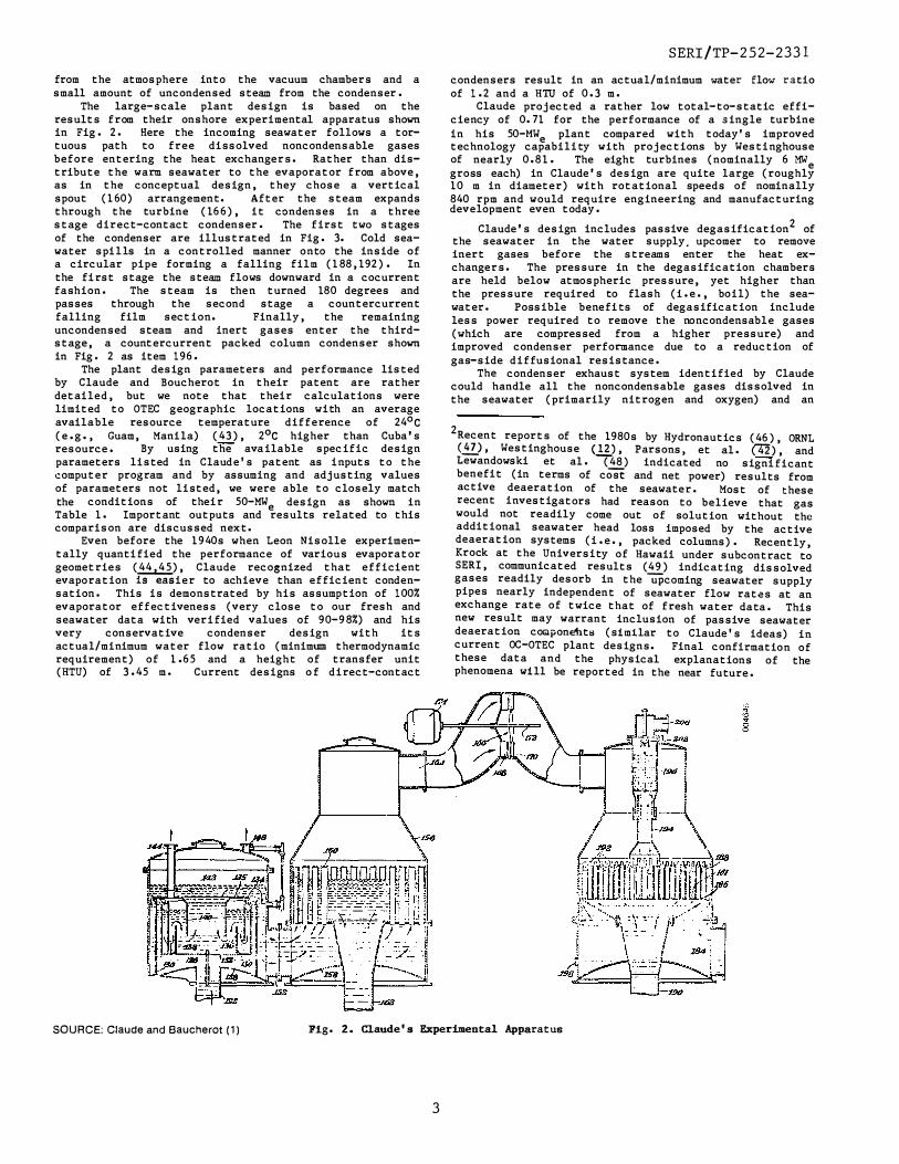
from the atmosphere into the vacuum chambers and a small amount of uncondensed steam from the condenser .
The large-scale plant design is based on the results from their onshore experimental apparatus shown in Fig . 2 . !!ere the incoming seawater follows a tortuous path to free dissolved noncondensable gases before entering the heat exchangers. Rather than distribute the warm seawater to the evaporator from above, as in the conceptual design, they chose a vertical spout (160) arrangement. After the steam expands through the turbine (16 6 ) , it condenses in a three stage direct-contact condenser . The first two stages of the condenser are illustrated in Fig . 3. Cold seawater spi l ls in a controlled manner onto the inside of a circular pipe forming a falling film (188, 192 ) . In the fi rst stage the steam flows downward in a cocurrent fashion . The steam is the n turned 18 0 degrees and passes through the second stage a countercurrent falling film section. Finally, the remaining uncondensed steam and inert gases enter the thirds tage, a countercurrent packed column condenser shown in Fig. 2 as item 196 .
The plant design parameters and performance listed by Claude and Boucherot in their patent are rather detailed, but we note that their calculations were limited to OTEC geographic locations with an average
°available resource temperature difference of 24 c °(e . g . , Guam, Manila) (43 ) , 2 c higher than Cuba's
resource . By using the ava ilable specific design parameters listed in Claud e ' s patent as i nputs to the computer program and by assuming and adjusting values of parameters not listed, we were able to closely match the conditions of thei r 50-MW design as shown ine Table 1. Important outputs and results related to this comparison are discussed next.
Even before the 1940s when Leon Nisolle experimentally quanti fied the performance of various evaporator geometries (44,4 5 ) , Claude recognized that efficient evaporation :LS"easier to achieve than efficient condensation . This is demonstrated by his assumption of 100% evaporator effectiveness (very close to our fresh and seawater data with veri fied values of 90-98%) and his very conservative condenser design with its actual /minimum water flow ratio (minimum thermodynamic requirement) of 1 . 6 5 and a height of transfer unit (HTU) of 3 . 45 m . Current designs o f d i rect-contact
SOURCE: Claude and Baucherot (1) Fig. 2. Claude's Experimental Apparatus
condensers result in an actual /minimum water flow ratio of 1 . 2 and a HTU of 0 . 3 m .
Claude projected a rather low total-to-static efficiency of 0. 71 for the performance of a single turbine in his 50-MW plant compared with today ' s improvede technology capability with projections by Westi nghouse of nearly 0 . 8 1 . The eight turbines (nominally 6 MWe gross each) in Claude's design are quite large (roughly 10 m in diameter ) with rotational speeds of nominally 840 rpm and would require engineering and manufacturing development even today .
2 Claude's design includes passive degasification of the seawater in the water supply. upcomer to remove inert gases before the streams enter the heat exchangers. The pressure in the degasification chambers are held below atmospheric pressure, yet higher than the pressure required to flash (i . e . , boil) the seawater . Possible benefits of degasification include less power required to remove the noncondensabl e gases (which are compressed from a higher pressure) and improved condenser performance due to a reduction of gas-side d i ffusional resistance .
The condenser exhaust system identified by Claude could handle all the noncondensable gases dissolved in the seawater (primarily nitrogen and oxygen) and an
2 Recent reports of the 1980s by Hydronautics (46 ) , ORNL (!!!.), Westinghouse (..!1}, Parsons, et al . (42) , and Lewandowski et al . (48 ) indicated no signi ficant benefit (in terms of cost and net power) results from active deaeration of the seawater . Most of these i;ecent investigators had reason to believe that gas would not readily come out of solution without the additional seawater head loss imposed by the active deaeration systems (i . e . , packed columns) . Recently, Krock at the University of Hawaii under subcontract to SERI, communicated results (49) indicating dissolved gases readily desorb in the upcoming seawater supply pipes nearly independent of seawater flow rates at an exchange rate of twice that of fresh water data . This new result may warrant inclusion of passive seawater deaeration coGlponehts (similar to Claude ' s ideas) incurrent OC-OTEC plant designs. Final confirmation ofthese data and the physical explanations of the phenomena will be reported in the near future .
SERI/TP-252-2331
3

Clau:le Progran Progran Canponent Description Design Inp.its Results
Evaporator wann water inlet tanperature (0c) 29 29 fairly high warm water resource stean production temperature (°G) 26 26 temperature, limita:I locatioas; effectiveness 1.0 actual evaporator effectiveness
-3 walill seawater flow rate x 10 (kg/s) 142 143 closer to 0.95 (30) stean production rate (kg/s) 710 703
'l\Jrbines stean inlet temperature (0c) 26 26 no evaporator--turbin e vapor
°stean ootlet temperature ( C) 13.S 13.S pressure loss is assuned; generator generator effici ency 0. 96 0.96 efficiency has not changed Ill.ICh since
power (Mol ) gross e so so 1932; Westinghouse (12) used a turbine turbine to tal-to-static efficiency 0.71 efficiency of o.81; turbine dianeter number of turbines 8 8 of up to S m possible with current turbine dianeter (m) 9. 7 technology (SS).
lbndenser cold water inlet temperature (0c) s s no turbine-condeaser pressure loss
°cold water outlet tanperature ( C) 10.S 10.s or diffuser recovery is asSl.llEd; °stean inlet tanperature ( C) 13.S 13.S measuranents in CD<mtercurrent
°stean outlet temperature ( C) 6 6 co rxlensers iniicate low l:ut vapor pressure loss (atm) 0 0 nomiegligible pressure losses (S6);
-3 cold seawater flow rate x 10 (kg/s) 76. 9 77.7 actual-to-tuininun fla.i" ratio actual/min:lmun flow rate 1.63 sbJuld be closer to 1.2.
Deaerat1ai gas rE!lX>val pressures ( atm) 0 . 06, 0 .10 0.06, 0.10 five stage canpression with intercooler cold-side gas °temperature ( C) S 5 used in simulat i on; Clauie did not have warm-side gas tanperature (°G) 29 29 adequate data to es t:lmate dissolved gas cold-side gas release (rr?'/s) 10 10.6 (max) in cold seawater or leakage through warm-side gas release (rdJ/s) 30 20. s (max) vacuun contaiI:ment structure; s:l:mulat i onpercentage of equilibriun gas releasa:I - 100 us ed a canpressor efficiency of 0.8. air leakage fran the aonosphere 0 cold-side canpressor power (l<W) 4SO 36S warm-side canpressor power (l<W) 800 70S
lbndenser exhaust volunetric flow of gas err?' /s) 14S 143 three-stage canpression with intercoolers gas °inlet temperature ( C) 6 6 was used with a ccmpressor efficiency NC gas release fran seawater (kg/s) 0.70 of 0.8. air leakage into heat exchangers (kg/s) - 1.1 canpressor power (l<W) 1000 1096
limn seawater flow loop total inlet an:! ootlet pipe l�h (m) - 1020 pipe l�h typical of land based plant; pipe rouglmess (m) 0.0127 Clau:ie used corrugat ed steel pipe in seawater velocity in pipes (m/s) 1 his experiments; water velocity in the evaporator liquid head loss (m water) 0.95 intake pipe was matched to Clau:le' s total liquid head loss (m water) 1.3S 1.29 design values; largest existing cam:ei:-canbined punp an:! mtor efficiency o.1s 0.79 cial pipe diameter na.i" is near 4 m. !XDIP power (l<W) 2500 2300 pipe diameter (m) 13.4
Chld seawater f1ow loop total inlet and ootlet pipe length (m) - 3370 Clau:le used 2-l<m-long pipe to obtain
°seawater velocity in pipes (m/s) 1 1 8 G cold water; low intake velocity; pipe diameter (m) 10 9.8 large corxleaser head loss imply corxlenser head loss (m water) 4.3 a rather inefficient contactor; the total head loss (m water) 5.8 5.2 height of transfer unit was increased canbined puDp an:! motor efficiency 0.8 0.79 ten-fold above experimental result s !XDIP power (l<W) 54SO 5040 (S6) to match Clau:le's head loss.
excess amount of gases caused by leakage. Using up-todate data on dissolved gases in seawater ( 49 , SO ) , we found his design to have an additional capacityof 2S% to account for atmospheric air leakage. Our estimates for leak rates using the guidance of Aerstin and S treet (Sl) result in leak rates nearly equivalent to the rate o-r- noncondensable gas evolution from the seawater . Using this as a conservative value, we anticipate handling about 50% more exhausted noncondensables than Claude foresaw. However, the relative amount of leakage with respect to the gas desorption rate is an unresolved issue still being debated among researchers today.
Claude was very concerned wit h his critics questioning his ideas that an open-cycle OTEC plant could be designed to produce a significant amount of ne t power (40) . This preoccupation perhaps led him to d esign !iTants for low component power requirements illustrated by the large 1 0-m-diameter cold water pipe with an intake seawater velocity of only 1 m/ s. From the standpoint of energy generated per total volume of water used, the ideal ratio of warm water to total water flow for an OTEC Rankine cycle is O . S (S2 ) . Claude used a value of 0 . 6 7 . Economics wil l always favor more warm water usage . Today, we consider the single item of greatest risk and highest cost to be the
SERI/TP-252-2331
4

\ __ '
\
194
192
� Jl586 -·-
I . . -
I . SOURCE: Claude and Bauch•rot (1)
<O " <O " 0 0
Fig. 3. Claude's Two-Stage Direct-Contact Condenser Detail
cold water intake pipe . Reducing the diameter and increasing the allowable seawater velocity in the cold water pipe (which results in hi gher pumping power) are economic trade-offs well worth considering in modern designs. Claude also recognized the importance of the cold water pipe in the overall engineering evaluation as demonstrated by his two unsuccessful attempts to deploy a cold water pipe for his experimental apparatus
·in Cuba.When he finally did succeed in laying a 2-km-long, 1. 7 5-m-diameter pipe and operating the power cycle, thepipe was destroyed after only 11 days in rough seas.
Claude ' s calculations of the 50-MW gross design e did no t include the losses associated wit h vapor passages be tween the evaporator and turbine, between the turbine and condenser, and within the condenser itself . He, however, had a quali tative feel for their importance since his design has smooth vapor paths with few sharp bends. We find these pressure drops can be significant in the thermodynamic performance evaluations . In add i tion, current designs provide for a mist removal device between the evaporator and turbine to prevent salt drop let carry-over, which causes erosion and st ress cor rosion problems (purity of the fresh water by-product is a concern as well ) . These pressure losses, which detract from the useful work of the system, along with increased seawater intake veloc ities, result in a lower net-to-gross power ratio. A current 50-MW (gross) plant with seawatere °resource temperatures of 2 5 C and s0c, accounting forvapor pressure drops and 2 m/ s seawater intake velocit ies, would yield a net-to-gross ratio of around 7 5% (�. Claude ' s 50-MW plant calculations projected� a net-to-gross ratio of 80%.
A NEW CONCEPTUAL DESIGN: SMALL-SCALE APPLICATIONS WITH INTEGRATED FLEXIBILITY
The SERI OTE C team, supported by its industrial and R&D subcontrac tors worked to combine the latest advances in OC-OTEC research to formulate and define a conceptual design of a small-scale (1 �!W ) facility. Componentedesign guidance was ini t i ally provided by the systems analysis program of Ref . (� • Table 2 summarizes the
projec ted facility operating cond i tions . The important features of the design ( 22) are summa rized below in terms of the major components, system integra tion, system analysis, instrumentation, and economics. Speci fically, the effort resul ted in a design wi th flow rates compatible with an existing but reconfigured 1 . 2-mdiameter cold water pipe using the thermal resource typical to Hawaii . Industry needs data at a scale that minimizes the uncertainty and therefore the investment risk . To design a prototype with this confidence level, we need actual seawater data at a scale that can be extrapolated within reason. Wherever possible, extrapolat ions using state-of-the-art component designs provided the technical data base for performance pred i c t ions . Given that caveat, our recent research on the OC-OTEC research facility leads us to some major conclusions described in the following subsec tions .
Components
Evaporators. Four pot ential evaporator geome tries were reviewed ; open channel flow (23 ,24,44, 4 5 ) , falling films ( 2 5, 31, 3 3 ) , downward fallingvert ical jets (30-32 , 3 4 , 355": -and upward flowing vertical spouts (26 ,30, 44,45)- Several criteria, required for an effective evaporator design, were def ined as:
• Low liquid-side pressure loss
• Low vapor-side pressure loss
• S imple inlet and exit mani folds
• High effectiveness
• Small volume
• Low liquid entrainment
• Low gas desorption
• Low fabrication cost
• Low susceptibility to biofouling and corrosion.
Using anal yt ical projections and experimental data, we evaluated the four contending evaporator geome tries. A summary of the evaluation, shows that vertical spouts have more merits and fewer negative aspects (high liquid entrainment ( 53 ) ] than the o ther geomet ries. Preliminary results with seawater on small scale (54 ) vertical spouts confirm fresh water test data obtained from full scale evaporators. Further testing on alternative components at a larger scale, at NELH, will provide final seawater test results for the comparison among contending evaporator geome tries. Our last five years of research show that seawater evaporat ion can be done in evaporators with approximately half the volume and using less than 30% of the hydraulic seawater pumping power disclosed in the 1 979 Westinghouse assessment (12 ) .-
Turbine. The turbine is perhaps the single most impo rtant component in the OC-OTE C system . The re-
. quired large volumet ric flow of steam coupled with the low amount of available specific energy results in turbine designs that are relatively large and expensive compared with conventional steam turbines. Small-scale OC-OTEC turbo-machinery (less than 5 MW ) is e w�..:iiin state-of-the-art capability because the ro tor is similar to designs for the low-pressure stages of the conventional steam turbines. Costs of these uni ts can be reduced by using composite materials ( 19), but several years of research and development effort is needed before they can be used .
A comparison of the last stage of a conventional power plant turbine and a turbine designed by the French for their conceptual OC-OTEC facili t y design for
.-
5
SERI/TP-252-2331

Component Description Caapoaent Description
1\Jrbine (dooble rotor) generated power aoo.o kW cold seawater fl.ow rate 1590.0 kg/s generator efficiency 0.97 actual/ininim.m water fl.ow rate 1.2 turbine efficiency 0.81 height of a transfer unit (!IlU) 0.3 m stean inlet tanperature 20.0 Oc frac tion of equilibriun stean ootlet tanperature 12.0 Oc gas release 0.8 stean inlet velocity 60.0 mis non::orrlensable gas evolution 0.028 kg/s stean outlet velocity 97.5 mis air leakage rate 0.004 kg/s
k.J/kg kgf 2 stean en thalpy drop 65.5 water loading 60.4 m s stean flow rate 14.7 kg/s Oindemer Exhaust a.upessor Train maxinun tip speed 450.0 mis mmber of canpression stages 4.0 hub-to-tip ratio 0.44 intercooler pressure drop 276.0 Pa ootside dianeter 2.8 m caopressor pressure ratio 3.1 rotational speed 3000.0 rpn in tercooler exit tanperature 7.0
Diffuser caopressor efficiency 0.80 recovery factor 0.62 power requiranent 75.9 inlet stean speed 97.5 mis liD:lll Seailater Flair Systea ou tlet stean velocity 60.0 mis inlet + discharge pipe length 1120.0 m stean inlet tenperature 12.0 OC seawater velocity in pipes 1.78 mis stean outlet tanperature 12.4 Oc nunber of 9CP berrls 10.0
Evaporator pipe diameter 1.22 m mist raooval pressure loss pipe friction factor 0.0114
coefficient 10.0 total inlet + discharge mist raooval stean velocity 30.0 mis pressure loss 23.45 kPa mist raooval. pressure drop 81.7 Pa evaporator height 0.5 m evap-mi.st pressure loss evaporator pressure loss 9.4 kPa
coefficient o.s density pressure loss 0.5 kPa stean generation velocity 23.0 mis total wann seawater pressure loss 33.4 kPa evap-mi.st pressure drop 2.4 Pa ccmbined punp-1110tor efficiency 0.786 stean generation tanperature 20.54 Oc punp di.aneter 0.84 m evaporator effectiveness 0.95 puq> speed soo.o wann seawater inlet tanperature 25.0 OC punp power requiranent 88.4 warm seawater outlet tenperature 20.76 OC QWl Seam.er Flair Systea wann seawater fl.ow rate 2130.0 kg/s inlet + discharge pipe length
. 3370.0 m
fraction of equilibriun seawater velocity in pipes 1.33 mis gas release 0.9 nunber of 9CP berrls • 10.0
noncorrlensable gas evolution 0.034 kg/s pipe dianeter 1.22 m air leakage rate 0.004 kg/s pipe friction factor 0.0123 spoot seawater velocity 2.0 s total inlet + discrarge evaporator planfonn area 35.2
�pressure loss 34.2 kPa
2 mist remval area 27.0 m average:i corrleaser height 0.46 m Direct Coot.act o.n, ISE'T" corrlenser pressure loss 8.7 kPa
diff .-corrl. pressure loss density pressure loss 4.2 kPa coefficient 1.0 total cold seawater pressure loss 47.1 kPa
diff.-corrl pressure loss 19.6 Pa canbined punp-1110tor efficiency 0.786 cocurrent pressure loss o.o Pa punp dianeter 0.66 m countercurrent pressure loss 200.0 Pa puq> speed 750.0 rpn cold seawater inlet tanperature 5.0 Oc punp power requiranent 92.7 kW cold seawater ootlet tenperature 10.6 OC
ost�as outlet tenperature 6.0 c �
total parasitic power requirement 257.0 kW outlet stean flow rate o.08 kg/s net power production 543.0 kW
Tahiti is given in Table 3. The major difference in operating conditions is the inlet steam pressure, which is considerably higher for the conventional turbine. However, the pressure ratio of the conventional turbine is only about 50% higher than the OC-OTEC turbine. Because of a lower power density, which corresponds to l ower pressure, the Tahiti design yields a gross power output of about S MW compared to 20-25 MW for the last stage of a conventional power plant turbine. Based on this comparison, existing turbine rotors are perhaps best suited for prototype designs to reduce risks. Because of the nature of their design, these are horizontal axis, double-ended turbines. Typical deli very times quoted by a reputable manufacturer for these conventional types of turbines adapted for OC-OTEC, are about two years with performance guarantees (2.2_)·
Condensers. The condenser research effort at SERI has primarily focused on direct-contact heat exchange. Direct-contact condensers are inherently more efficient than standard surf ace type exchangers because the temperature drop across the solid surface interface is
3 eliminated. Without water production the proposedcondenser configuration (based on criterion similar to that for the evaporator design) is a direct-contact cocurrent region followed by a direct-contact countercurrent final stage, somewhat similar to Claude and
3However, the production of potable fresh water from an OC-OTEC system requires a surface condenser or a water-to-water heat exchanger with a fresh water or nontoxic imiscible f luid direct-contact condenser.
6
SERI/TP-252-2331

Table 3. Comparison Between Conventional Last Stage and Tahiti OC-OTEC Turbine Conditions
Parameter OC-OTEC Last Stage
Inlet pressure (Pa) 2700 15,000
Exit pressure (Pa) 1100 4000
Isentropic enthalpy drop (kJ/kg) 120 200
* Gross power (MW ) 4-5 20-25 e
Speed (rpm) 1500 1500
Tip diameter (m) 5.6 5.6
*nouble pass turbine
Boucherot's design (1). Evaluation of various condenser geometries ( 56 ,57) indicates that this condenser subsystem is able to achieve low vapor-side pressure losses (<200 Pa) with water- and steam-side effectiveness of over 0.8 at low cost. Approach steam velocities to the cocurrent region, where 90% of the steam is condensed, should be about 20 m/s for a costeffective subsystem design. This condenser configuration represents a significant improvement over Claude's designs requiring 25% less water flow and about an order of magnitude lower liquid-side pressure loss yet with a higher number of transfer units for the same height.
Noncondensable Exhaust Handling. The warm and cold seawater feed streams subjected to a reduction in pressure desorb dissolved noncondensable gases (primarily nitrogen and oxygen). These noncondensables along with any containment leaks must be continuously exhausted from the facility to maintain a low system pressure. Several options for gas exhaust systems were examined based on a conservative design point of 100% evolution of dissolved gases and an equivalent atmospheric air in-leakage. Calculations indicate that conventional designs for hardware using four to six centrifugal compressor stages with interstage coolers would limit losses to about 10% of system gross power output. Although not off-the-shelf equipment, centrifugal compressors are readily available from many manufacturers in the size range appropriate for this application. The operating conditions, however, would require redesigning components such as bearings and seals.
System Integration. An integrated 1-MW OC-OTEC e facility is shown in Fig. 4. The entire vacuum enclosure and water feed and drain systems are integrated into a concrete cylindrical enclosure of 15-m diameter and 30 m height. The evaporator and condenser are located at their respective barometric levels. The turbine (horizontal axis, double pass) is located in the center directly above the evaporator. The top hatch of the enclosure allows easy access for installation and removal of the turbine and for inspection, maintenance, and repair. A round dome cover, although more condusive for vacuum vessels, was eliminated for cost reasons.
Warm seawater enters the vacuum enclosure through an inner annulus. Warm water effluent is drained through a central discharge pipe. Cold water enters through an outer annulus and is distributed to the direct-contact condensers located around the periphery. Cold water effluent like the warm water effluent discharges through a middle annular passage. Four separate pools directly underneath the enclosure separate
the water feed and discharge streams and provide for damping of water level fluctuations. The water columns in the intake and drain passages reduce the pressure difference the structure must withstand.
A surface condenser with a small fresh water production capacity of 0.63 kg/s is located outside the enclosure at ground level for easy access and maintenance as merits which were traded off against the additional pressure drops caused by steam routing obvious in this arrangement. The gas exhaust system, located at ground level, has obvious merits with no foreseen compromises.
Provisions are also made to deaerate the intake water passively in the upcomer as shown.
Degasification. The effect of evolved noncon-densable gases on the evaporator and turbine performance is inconsequential. Evolution of noncondensables in the evaporator feed stream contributes to generation and reformation of the phase interface enhancing evaporation. However, at the evaporator saturation pressure, the noncondensable gases at a volume fraction of less than 0.3% are unlikely to have any major impact on surface renewal or liquid mixing. Noncondensables from the evaporator flow through the turbine and make a slight but neglible contribution to the power output.
The reduction in condenser effectiveness due to noncondensable gases and the accompanying increase in the condenser pressure strongly affects the turbine output by 10-15%. However, the trade-off in system parasitic power loss between degasification and no degasification shows only marginal improvements wnen active degasifiers (e.g., packed columns) are used. Research on passive barometric degasifiers (e.g., riser column direction changer) is in progress to quantify their potential for reducing the overall noncondensable exhaust pumping power.
Structure. For structural needs many new mate-rials, such as petrochemical derivatives, polyethylene, vinyl, and carbon-based graphite epoxy were considered along with the more conventional building materials, such as steel, steel alloys, other metals, and various types of concrete.• A comparison based on permeability, corrosion protection, leaching, and cost leads to concrete as the recommended choice for our small-scale OC-OTEC structural design (58). Several architectural options were examined, an�a vertical cylinder was identified as the most cost effective. Test facility operation needs dictated that internal components such as evaporators, condensers, gas removal, and turbine areas remain accessible to allow for experimental changes. Construction of the relatively large vacuum vessel (15 m diameter x 30 m height) will use slip-form techniques to minimize construction joints. The construction materials and procedures are commonly applied techniques in the construction industry.
Flow Hydraulics. To obtain an understanding of liquid side losses and the associated pumping power requirements, calculations were performed to identify areas of significant loss contributions. The primary pressure loss occurring in the seawater inlet pipes is caused by friction and is proportional to the square of the seawater velocity. Aside from the inlet pipe loss, hydrostatic pressure losses dominate. The interactions associated with waves were found to be sufficient!� damped by relatively small holding pools of about 10 mplanform area. Ocean dynamics associated with tides are of a quasisteady state nature due to the relatively long periods (12 hours and more) of tidal fluctuations. To achieve continuous system operation, flow must be maintained at low and high tide. We realize that the hydrostatic loss at low tide being a maximum is a primary design constraint.
7
SERI/TP-252-2331

i.---- 7.0 m --- .i
Pneumatic seal
23.0
Manhole access
15.4
Vertical
baffle-'--'-----'
\ Cold water
in
3.0 �
2.0
0.0
11 -3.0 I
cw out
11 !I II II
I II I
Warm water
in
It 11 II
I Removable steel hatch
E 0 cci
Pres tressed / concrete
cylinder vacuum chamber
_,- Noncondensable gas annular duct
1-m Dia.
condenser
L� \ I
Noncondensable
gas exhaust
system
Fig. 4. Sectional View of the Integrated 1-MWe Research Facility Design
Vapor Side Flow Analysis. Calculations were performed to evaluate the vapor passage losses. A typical pressure distribution through the system yields about 3% (40 Pa) across the mist removal device, 23% (315 Pa) for turbine losses, 62% (930 Pa) across the turbine for useful work, and 13% (200 Pa) across the condenser. This emphasizes the importance of maintaining low losses through the evaporator, condenser, and intercomponent passages to maximize the work out of the turbine.
System Analysis. A systems model with a series of subroutines that predict the performance of the various components or subsystems and an executive routine that integrates the appropriate input/ output subroutine val ues to ensure system compatability was developed to examine the thermodynamic performance of OC-OTEC systems (42). Thermodynamic optimization to minimize parasitic losses for the research facility results in turbine inlet and outlet temperatures of about 20°c and 11°c, respectively. For an inlet cold water pipe diameter of 1. 2 m and length of 27 SO m the net/ gross power ratio and net power production as a function of cold water flow rate are shown in Fig. S. This graph
indicates that if the cold water pipe is a dominate cost the best operating conditions would be that of maximum power output. This, of course, does not correspond to the best net/gross ratio (0. 851) but rather a value of about Q.60 for this configuration. Overall system economic optimization, however, requires further consideration. Efforts are underway to combine the thermodynamic systems model with economic analysis to arrive at the best system designs based on various optimization criteria beyond the results presented below.
Instrumentation. Several basic measurements are required, including: flow rates (warm seawater, cold seawater, fresh potable water, effluent discharges); pressure (evaporator, condenser, turbine, exhaust system); temperature (warm seawater, cold seawater, evaporator vapor, turbine exhaust, condenser exhaust, exhaust system); dissolved gas content (warm seawater, cold seawater), and power (generator output, pumping power, exhaust power). Further instrumentation details may be found in Ref. (22).
All measurements are routine and within state-of-the-art techniques. The objective of the instrumen-
SERI/TP-252-2331
8

1.0 500
0.9 450
0.8 400 z Ci) !2."' 0.7 350 "'O 0 0 .... � Cl..... 0.6 300 (1) Qi ... .s "'O
0.5 ...
250 0 0 Q. � c:
0.4 200 $l .... a; 5· ;: 0.3 ::J
150 0 ;1l:" CL � 0.2 100 � 0.1 50
0.0 0 0.0 0.5 1. 0 1.5 2.0 2.5 3.0 3.5 4.0
Cold water flow rate (m3/s) Fig. 5. Typical Variation of the Net-to-Gross Power
Ratio and Net Power Output With Cold Water Flow Rate for a 1.2 m Diameter Inlet Pipe
� "' "' 0 0
tation is to provide researchers with data to evaluate the performance of various component options. Some of the measurements may also be used for monitoring, controlling, and optimizing overall facility operations.
Economics. Values solicited from various manufacturers and engineering projections show OC-OTEC plant capital investment costs ranging from off-the-shelf equipment at $12/W to a projected improved cost of about $3/W for routinely produced facilities at large scales (i.e., )20 MW net). Fig. 6 shows our estimate e of busbar energy cost as a function of net power production over the range of 1 to 20 MWe for two fixed charge rates (0. 17 and 0. 06). This energy cost is found by levelizing the capital cost of the plant over its lifetime and accounting for return on investment, operatioh and maintenance, and actual operating time. Specifically, the amortization of plant capital cost is done using the fixed charge rate, an economic parameter defined by
, , __ ,�,
,
This parameter accounts for the escalation rate i the rate of return on investment r, and plant life N. For our study we have used fixed charge rates that give reasonable bounds for escalation and return on inves t:nent. (For an escalation of 8%, rate of return of 30%, and 30-year plant life the fixed charge rate is 0 . 17. For an escalation of 6%, rate of return of 10%, and a plant life of 30 years the fixed charge rate is 0. 06). Further, we have assumed that the operation and maintenance costs are 1% of the total plant capital cost per year, the plant produces electricity 90% of the year (capacity factor of 0. 9). The busbar energy cost can be defined as
BBEC = ( (FCR x K/CF) + OM x K/CF]0. 114
where BBEC = busbar energy cost, $/kWh FCR fixed charge rate, $/$-yr
K = plant capital cost, $/W CF = capacity factor OM = operation and maintenance factor
0. 114 = unit conversion constant (W-Yr to kW-h}
SERI/TP-252-2331
9
0.50
0.45
.c 0.40 s: .¥ 0.35 ...... � ;;; 0.30 0 u >- 0.25 Cl ... Q) c: 0.20 Q) .... al 0.15 .0 en ::l ID 0.10
0.05
0.00 0 2 4 6 8 1 0 12 14 16 18 20
Net power production (MWe) Fig. 6. Recommended Research Facility Instrumentation
Requirements and Their Locations
In addition, if certain components have projected life spans less than overall plant life, the energy cost must be proportionally increased to account for the added capital cost. It is clear that the economic parameters that are constantly changing from year to year must be carefully evaluated prior to assessing the overall economic feasibility of an OTEC plant.
Presently, the dominant costs of OC-OTEC plants are related to the seawater feed pipes (especially driven by length) and associated deployment and the vacuum containment structure. Recent research has reduced the heat exchanger costs to an extent where the cost is insignificant at the level of uncertainty in cost analysis (iQ_).
FUTURE DIRECTIONS
Although this paper reemphasizes the Westinghouse conclusion that OC-OTEC is a technically feasible costeffective renewable energy alternative today, further candidate areas of performance and cost improvements
quantities of noncondensable gases may evolve must be quantified to design the appropriate heat exchanger size (direct contact or surface). Composite blading for the turbine can further improve the economics of the fixed capital investment costs. Instrumentation required to quantify component performance was described. The experimental data needs for OC-OTEC reveal that experimental facilities with a flow capability of only a few thousand gallons of seawater per minute could evaluate heat exchangers for modularly scalable units to sizes in excess of 5 MW · Although ethe practicality of producing fresh water using surface condensers in an OC-OTEC plant is not new (61), achieving dual product outputs is important to improve the cost effectiveness of OTEC plants. Two recently completed analytical studies (62,63) have explored the commercial viability of this scheme. Both conclude a near-term potential for commercial viability of the OCOTEC concept for production of fresh water and electricity at relatively small (<10 MW) sizes.
CONCLUSIONS
This paper has

• Assessed the impact of recent research results on the thermodynamic performance of a small-scale, shorebased OC-OTEC system
• Provided limited economic evaluations of key OC-OTEC components integrated into a design concept
• Identified issues that require further investigationto reduce the uncertainties in projected system performance.
Progress since the time of Claude has been slow, but, more recently, steady because of the facilities in the continental United States testing with fresh water ( 31 , 64 ) , and in Hawaii ( 65 ) , using warm and cold seawater from the ocean on acontinuous basis. Efforts in these facilities have resolved a number of unknown issues and uncertainties in low-temperature directcontact heat exchange.
Combining these technical results with the economical projections we can conclude that:
• Most of the economies of scale for an OC-OTEC plantcan be realized for plants less than 10 MW in s ize e
• Plants of 10 MW size can ·be built economicallye ( within 20% of optimum estimates) using multiplestate-o f-the-art turbines and cold water pipes while using the new experimental data bases as the designstrategy for cost-effective, direct-contact heat exchangers.
• There are signi ficant commercial opportunities for10-Ml< plants producing electricity and fresh water e because of the cost reductions from dual product outputs
• The technological risks still appear to be high for OC-OTEC because of a lack of applicable seawater data at a scale amenable to extrapolation for commercialventures.
An analysis of the research data needs for the next step of meaning ful open-cycle OTEC development plan reveals that an experimental fa't:ility integrating all the essentials of a complete system is required. This design case study describes such a facility that could provide advanced research data and verify the cycle feas ibility in terms of performance, cost, and reliability of key components and systems.
Acknowledgments
We would like to express our gradi tude to Benjamin Shelpuk, manager of the SERI Oceans Program for providi ng guidance over the last five years of this research and to the U.S. Department of Energy, Ocean Bnergy Technology Division, for their financial support in carrying out this work. The technical contributions of the perso nnel involved in this work from Creare Research and Development, Inc., Science Applications, Inc., and T. Y. Lin are gratefully acknowledged. The assistance offered by the team at the Natural Energy Laboratory of Hawaii, Research Corporation University of Hawaii, and Hawaii Natural Energy Institute of the University of Hawaii is appreciated.
REFERENCES
( 1 ) Claude, G. and Boucherot, P., inventors Paris, France, "Method and Apparatus for Obtaining Power from Sea Water, " U.S. Patent 3,006, 985, 1935.
( 2 ) Beck, E. J., inventor Ventura, Cali f., "Ocean Thermal Gradient Power Plant, " U.S. Patent 3, 967,449, 6 July 1976.
( 3 ) Ridgway, s. and Lee, C. K. B., "Installation and Operation of the Mist Lift Ocean Thermal Energy Conversion ( OTEC) Process at Keahole Point Hawaii , " Research and Development Associates, Inc., RDA-TRP1 2 6 200-001, Marina Del Ray, CA, October 1983.
( 4 ) Ridgway, S. L., "The Mist Flow Ocean Thermal E nergy Conversion Plant, " Proceedings of the Fourth Ocean Thermal Energy Conversion Conference, New Orleans, LA, 1 9 7 7 .
( 5 ) Zener, c. and Fetkovich, J., "Foam Solar Sea Power Plant, " Science, Vol. 189, 1975.
( 6 ) Cohen, R., "Electric Power Generaion--Ocean Thermal Energy Conversion ( OTEC) , " Chapter 13, Solar Energy Handbook, Marcel Dekker, Inc.
( 7 ) Cohen, R. "Energy from the Ocean, " Phil Trans. R. Soc. Land, A 307, PP• 405-437.
( 8 ) Lavi, A., Energy, The International Journal, Vol. 5, No. 6, Pergamon Press, New York, June 1 9 80.
( 9 ) Apte, et al., "Ocean Thermal Energy Conversion Reference Manual , " PRC llR-4017, PRC System Services, McLean, VA, August 1981.
( 10 ) "Ocean Energy Technology Assessment, " Meridian Corporation, Falls Church, VA, July 1983.
( 1 1 ) Bharathan, D., Kreith, F., and Owens, w. L., "An Overview of Heat and Mass Trans fer in Open Cycle OTEC Systems, " SERI-TP-252-1854, Solar Energy Research Institute, Golden, CO, 1983.
( 1 2 ) "100 MWe OTEC Alternate Power Systems, Final Report, " Westinghouse Electric Corporation, Power Generation Divisions, Lester, PA., March 1979.
( 13 ) Boot, J. L. and McGowan, J. G., "Feasibility Study of a 100 Megawatt �pen Cycle Ocean Thermal Di fference Power Plant, " Report NSF/RANN/SE/GI-34979/ TR/ 74/3, Mechanical Engineering Department, University o f Massachusetts, Amherst, August 1974.
( 1 4 ) Heronemus, W. E., et al., "Technical and Economic Feasibility of the Ocean Thermal Differences Process, " Third Quarterly Progress Report, NSF/RANN/SE/GT-34979 /PR/ 74/3, University of Massachusetts, Amherst 1 December 1974.
( 1 5 ) Brown, c. E. and Wechsler, L., "Engineering an Open Cycle Power Plant for Extracting Solar Energy from the Sea, " Offshore Technology Conference, OTC No. 2254, 1 9 75.
( 1 6 ) Anderson, J. H. and Anderson, H., Jr., "A Summary of the Anderson and Anderson Analysis of the Sea Solar Power Process " 1964-1 9 7 2, " NSF/ RANN/SE/ GI-34979/TR/ 73 / 5, Univers ity of Massachusetts, Amherst, March 1973.
( 1 7 ) Zener, c., "Solar Sea Power, " Phys ics Today, Vol. 26, No. 1, 1 9 73, PP• 48-53.
( 18 ) Watt, A. D., Mathews, F. s., Hathaway, R. E., "Open Cycle Ocean Thermal Energy Conversion, A Preliminary Engineering Evaluation, Final Report, " Colorado School of Mines, Golden, CO, 31 December 1977.
( 1 9 ) Coleman, W. H., Rogers, J. D., Thompson, D. F., Young, M. I., Westinghouse Electric Corporation, "Open
10
SERI/TP-252-2331

Cycle-OTEC Turbine Design, " AIAA 2nd Terres trial Energy Systems Conference, December 1 9 8 1 .
( 20 ) Van Ryz in, J. C . , "The Design and Development of a Deep Water Ocean Intake Pipeline for the Seacoast Test Facility in Hawaii , " Third Arctic Engineering Symposium, New Orleans, LA, February 1984.
( 2 1 ) Svensen, N . A., " An Overview of the OTEC-l Design, " Proceedings of the Sixth Ocean Theraml Energy Conversion Conference, G . L. Dugger, ed . , Washington, DC, June 1 9 79, pp. 5 . 3-1 through 5 . 3-15 .
( 2 2 ) Penney, T . , Bharathan, D . , Alt hof, J. and Parsons, B . , " An Assessment of Technology for a Small-Scale Shore-Based Open-Cycle Ocean Thermal Energy Convers ion System--A Design Case S tudy for an Integrated Research Facility, " SERI/TR-252-2184, Solar Energy Research Ins t itute, Golden, CO, forthcoming .
( 2 3 ) L ior, N ., and Gfrei f, R . , " Some Basic Observations on Heat Trans fer and Evaporation in the Horizontal Flash Evaporator, " Desalination, 33, pp. 2 69-286, 1980 .
( 24 ) Lior, N . , and Purushothaman, v. M . , "An Experimental S tudy of Flash Evaporation in Liquid Pools, " Subcontract XM-9-81 90-1, Solar Energy Research Inst i tute, Golden, CO, May 1983 .
( 2 5 ) Wassel, A. T . , Bugby, D . C . , Mills, A. F. and Farr , J . L . , Jr ., "Design Methodology for DirectContact Falling Film Evaporators and Condensers for Open Cycle Ocean Energy Thermal Energy Conversion, " SAI-083-83R-001, Science Applications, Inc . , El Segundo, CA, February 1982 .
( 2 6 ) Ghiaasiaan, S . M., and Wassel, A. T . , "Inverted Ver tical S pout E�aporators for Open Cycle Ocean Thermal Energy Conversion, " International Communications in Heat and Mass Trans fer, Vol . 10, pp. 5 1 1-524, 1 983 .
( 2 7 ) Kogan, A . , Johnson, D . H . , Green, H . J . , Olso n , D . A . , "Open Cycle OTEC System with Falling Jet 1>•1aporator and Condenser, " Proceedings of the Seventh Ocean Energy Conference, Washington, DC, June 1980, p p . 1 6 . 4 . l - 9 .
( 28 ) Green, H . J . , Olson, o . A . , Bharathan, D . , and Johnson, D . H . , "Measured Performance of Falling Jet Flash Evaporators , " SERI/TP-6 3 1-1270, Solar Energy Research Ins titue, Golden, CO, November 1 982 .
( 29 ) Kreith, F . , Olson, D . A . , Bharathan, D . , Green, H . J . , "A S tudy of Falling Jet Flash Evaporators, " SERI/TP-252-1415, Solar Energy Research Ins t i tute, Golden, CO ., November 1982 .
( 3 0 ) Bharathan, D . , Penney, T. R . , "Flash Evaporation from Falling Turbulent Jets, " SERI/TP-252-1853, Solar Energy Research Insti tute, Golden, CO, January 1983 .
( 3 1 ) Sam, R. G . and Patel, B . R . , "Open Cycle Ocean Thermal Energy Conversion Evaporator/Condenser Test Program-Data Report , " TN-340 C reare Research and Development, Inc ., Hanover, NH , October 1982 .
( 32 ) Kim, s. , " An Inves tigation of Heat and Mass Transport in Turbulent Liquid Jets, " prepared for DOE/ SERI under Grant No . DE-FG02-90CS89501, February 1983
( 3 3 ) Hajiloo, M., "Experimental Inves tigation of Interfacial Shear in Downward, Two-Phase, Annular, Co-
Current Flow wi th Diameter Effects, " prepared for DOE/SERI under Grant No . DE-FG02-80CS89501, February 1983 .
( 3 4 ) Ofer, s. , "An Experimental Study of Evaporation from Round Turbulent Water Jets, " prepared for DOE/ SERI under Grant No . DE-FG02-80CS-89501, February 1983 .
( 35) Leininger, T. F . , "Mass Trans fer in Round Turbulent Water Jets, " prepared for DOE/ SERI under Grant No . DE-FG-02-80CS89501, February 1 983 .
( 3 6 ) Claude, G. and Boucherot, P . , " Sur ! ' Utilisa tion de 1 1 Energie Thermique des Me rs, " Academie des Sciences, 22, 25 November 1926, pp . 929-933, 1005-1 006 .
( 3 7 ) Claude, G . "Utilization of the Heat Energy of the Sea, " Academie des Sciences Comptes Rendus, V. 185, No . 19, Nov. 7 1927, pp. 987-990 ( French) .
_
( 38) Bautaric, A., "Utilization of the Heat Energy of Oceans, " Chaleur et Indust rie, Vol . 9, No . 94, Feb . 1 928, p p . 5 5-62 ( French ) .
( 3 9 ) Claude, G. and Boucherot, P . , "On the Utilization of the Thermal Energy of the Seas, " Academie des Sciences--Compt es Rendus, Vol . 186, No . 23, 4 June 1 9 28, pp. 149 1-1495 ( French ) .
( 40 ) Claude, G . , " Power From the Tropical Seas, " Mechanical Engineering, Vol . 52, No . 12, December 1 930, PP• 1039-1044 .
( 4 1 ) Massart, G . L . , "The Tribulations of Trying to Harness Thermal Power , " Marine Technology Society Journal, Vol . 8, No . 9, October-November 1974, pp . 18-2 1 .
( 4 2 ) Parsons, B . , Bharathan, D. , Althof, J . , "Thermodynamic Systems Analysis of Open-Cycle Ocean Thermal Energy Conversi.on (OTEC ) , " SERI/TR-252-2234, Solar Energy Research Institute, Golden, CO, forthcoming .
( 4 3 ) "Large-Scale Distribution of OTEC Thermal Resource, " map by Ocean Data Systems, Inc ., 1 9 78 .
( 44) Nisolle, L . , "Rapport Sur Les Essais d ' auto Evaporation, " Pro fesseur a' l ' Eco le Centrale des Arts et Manufactures, presented to Commission Technique de l ' energie Thermique des Mers ( in French) , n . d .
( 4 5 ) Nisolle, L . , "Utilsat ion de l ' Energie Ther:nique des Mers-les Problems de Fonctionnement, " Societe des Ingeniurs Civils de France, Paris, 1947 .
( 46 ) Lindenmuth, w . , Liu, H . , and Poquet te, G ., "Seawater Degasi fication in OC-OTEC Risers, " 8031-1, Hydronautics, Inc . , Laurel, MD , March 198 2 .
( 4 7 ) Golshani, A . and Chen, F . C . , "Ocean Thermal Energy Conversion Gas Desorption S tudies, Vol . 2, Degasif ication in a Packed Column and a Barometric Intake System, " ORNL/TM-7438/V2, Oak Ridge National Laboratory, Oak Ridge, TN, September 198 1 .
( 48 ) Lewandowski, A. A . , Olson, D . A . , and Johnson, D . H . , "Open-Cycle OTEC Systems Per formance Analys is , " SERI/TR-631-692, Solar Energy Research Inst itute, Golden, CO, 198 0 .
( 4 9 ) Krock, H . , Zapka, M . , Noncondensable Gas Exchange in the OC-OTEC Process-Experimental Seawater Results
11
SERI/TP-252-2331

at NELH , Report 57 , J .K. K. Look Laboratory, University o f Hawaii , Honolulu, Aug. 1984.
( SO) Krock, H. J . , "Gas Analyses of Water Samples for OTEC Program , " No. 15 , Honolul u , Hawai i , University of H awaii , Department of Ocean Engineering , 1981.
( 5 1 ) Aerstin, F. and S tree t , G . , Applied Chemical . Process Design, 1978 Plenum Pre s s , New York.
( 52 ) Johnson, D. H., "The Exergy of j:he Ocean Thermal Resource and Analysis of Second-Law Ef feciencies of Idealized Ocean Thermal Energy Conversion Power Cycles , " Energy , Vol . 8 , No . 1 2 , PP• 927-946 , also SeRI/TR-252-1420 , Solar Energy Research Ins t i tute 1983 .
( 53 ) Bharathan , D . and Penney, T . R . , "Mist Eliminators for Water Produc tion from Open-Cycle OTEC Sys tems , " SERI/TP-252-1 9 9 1 , Solar Energy Research Ins t i tut e , Golden , CO , 1983 .
( 54) Larson-Bass e , J . , "Open-Cycle Ocean Thermal Energy Convers ion Experiment , " Solar Energy Research Ins t i tut e , Golden, CO , August 1983.
( 55) Penney T., Le tter Report on Rateau Turbines from A. T. Wassel , Science Applica tions , Inc., Hermosa Beach, CA. , 14 July 1983.
( 5 6 ) Bharathan, D. and Altho f , J. , " An Experimental S tudy of Steam Condensation on Water in Countercurrent Flow in the Presence of Inert Gases , " paper to be presented at ASME-WAM, New Orleans , LA., 1984.
( 57 ) Ocean Research Group , interim data report on direc t-contact countercurrent condenser tests conducted at SERI during FY 1983 , Solar Energy Research Ins t i tut e , Golden, CO , 30 September 1 983 .
( 58 ) Ludke , R. P . and Chow , P . Y. , " Structural Aspects of an Advanced Research Open Cycle OTEC Facil i ty , " Proceedings o f the Third Offshore Mechanics and Arc tic Engineering Symposium, Vol. 2, February 1 984 •
( 5 9 ) Stole r , P., "Pulling the Nuclear Plug , " Time , 13 February 1984, pp. 34-42 .
( 60 ) Parsons , B. , Letter Report from Javier Valenzuela , Creare Research and Development , Inc . , Hanover , NH , 17 May 1984.
( 61) Nizery , A., Utilization of the Thermal Potential o f the Sea for the Produc tion of Power and Fresh Water , Ins t i tute of Engineering Research, University of California , Berkeley , CA . , March 1954.
( 62 ) Wes tinghouse Electric Corporation , A S tudy to Determine the Commercialization Po tential of Open Cycle OTEC Water Plants , prepared for Mari t ime Adminis tration, PB80-199060 , NTI S , July 1980.
( 63) "Preliminary OTEC Study Completed , "The Solar Collect or Vol . 9, No. 2, Spring 1 984 .
( 64 ) "An Overview of SERI Solar Thermal Research Facilities , " SERI/SP-631-760, Solar Energy Research Ins t i tute , Golden , CO , 198 1 .
( 6 5 ) Hawaii Natural Energy Ins t i tute Annual Report , July 1 982--June 1983 , University of Hawaii at '1anoa , Honolulu , HA .
1 2
SERI/TP-252-233 1