Embed Size (px)
Citation preview

Henny Penny Heated Holding Cabinet Model HHC-900 Model HHC-902 Model HHC-903 Model HHC-906 Model HHC-908 Model HC-15
TECHNICAL MANUAL


Models HHC-90X/HC-15
TABLE OF CONTENTS
Section Page
Section 1. TROUBLESHOOTING ............................................................................................. 1-11-1. Introduction ...................................................................................................... 1-11-2. Safety ............................................................................................................... 1-11-3. Troubleshooting ............................................................................................... 1-1
Section 2. MAINTENANCE ...................................................................................................... 2-12-1. Introduction ...................................................................................................... 2-12-2. Test Instruments ............................................................................................... 2-12-3. Removal of Module Access Panel ................................................................... 2-12-4. Module Removal .............................................................................................. 2-12-5. Removal of Module Housing .......................................................................... 2-22-6. Fuse .................................................................................................................. 2-32-7. Power Switch ................................................................................................... 2-42-8. Thermostat ....................................................................................................... 2-52-9. Indicating Lights .............................................................................................. 2-62-10. Thermometer .................................................................................................... 2-7 2-11. Heater ............................................................................................................... 2-82-12. High Limit ....................................................................................................... 2-92-13. Blower ............................................................................................................. 2-102-14. Door Gasket Replacement ............................................................................... 2-122-15. Wiring Diagrams ............................................................................................. 2-13
Section 3. PARTS INFORMATION ........................................................................................... 3-13-1. Introduction ...................................................................................................... 3-13-2. Genuine Parts ................................................................................................... 3-13-3. How to Find Parts ............................................................................................ 3-13-4. How to Order ................................................................................................... 3-13-5. Prices ................................................................................................................ 3-23-6. Delivery ............................................................................................................ 3-23-7. Warranty ........................................................................................................... 3-23-8. Recommended Spare Parts for Distributors ..................................................... 3-2
106 FM06-021 iRevised 9-23-14

Models HHC-90X/HC-15
1-3. TROUBLESHOOTING To isolate a malfunction proceed as follows: 1. Clearlydefinetheproblemorsymptomandwhenitoccurs. 2. Locate the problem in the troubleshooting table. 3. Review all possible causes, then one at a time work through the list of corrections until the problem is solved.
If maintenance procedures are not followed correctly, injuries and/or property damage could result.
SECTION 1. TROUBLESHOOTING
1-1. INTRODUCTION This section provides troubleshooting information in the form of an easy to read list.
Ifaproblemoccursduringthefirstoperationofanewcabinet,recheck the Installation Section of the Operator’s Manual.
Before troubleshooting, always recheck the Operation Section of the Operator’s Manual.
203 1-1
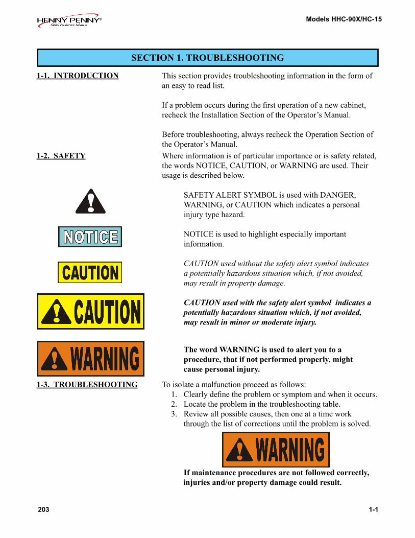
1-2. SAFETY Where information is of particular importance or is safety related, the words NOTICE, CAUTION, or WARNING are used. Their usage is described below.
SAFETY ALERT SYMBOL is used with DANGER, WARNING, or CAUTION which indicates a personal injury type hazard. NOTICE is used to highlight especially important information.
CAUTION used without the safety alert symbol indicates a potentially hazardous situation which, if not avoided, may result in property damage.
CAUTION used with the safety alert symbol indicates a potentially hazardous situation which, if not avoided, may result in minor or moderate injury.
The word WARNING is used to alert you to a procedure, that if not performed properly, might cause personal injury.

Models HHC-90X/HC-15
PROBLEM CAUSE CORRECTION
1-2 203
OPERATION
A. Product not •Doorsareleftopen •Keepdoorsclosedexceptto holding load and unload product temperature • Thermostatsettoolow • Increasethermostatsettingbymoving the knob to a higher number setting
• Gaskettornorworn • ReplacegasketperDoorGasket Replacement Section • Heaternotworking • Checkheater;replaceperHeater Section
• Blowernotworking • Checkblower;replaceperBlower Section
• Productheldtoolong •Holdproductonlyforrecommended time
• Loworimpropervoltage •Usingmeter,comparereceptacle voltage to data plate voltage
B. Cabinet • Toomuchhumidityinsidethecabinet • Emptywaterfromthewaterpan steaming - product •Holdingproducttoolong •Holdproductforrecommendedtime becoming soggy •Ventnotsetproperly(units •AdjustventperOperator’sManual with vent adjustment only) C. Productdry •Nowaterinpan • Removepanandputinapproximately 1” of hot water
HEATING SYSTEM
A. Unitwill • Faultythermostat • CheckthermostatperThermostat
• Faultyhighlimit • CheckhighlimitperHighLimit Section
• Faultyheater • Checkheater;replaceperHeater Section
• Faultywiring • Checkwiringforlooseconnections or broken wires and repair as needed
not heat Section
1-3. TROUBLESHOOTING (Continued)
Models HHC-90X/HC-15
PROBLEM CAUSE CORRECTION
203 1-3
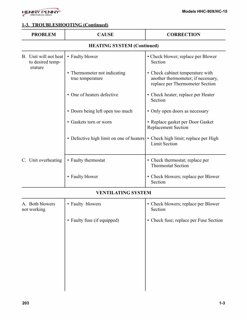
HEATING SYSTEM (Continued)
B. Unitwillnotheat • Faultyblower •Checkblower;replaceperBlower to desired temp- Section erature • Thermometernotindicating • Checkcabinettemperaturewith truetemperature anotherthermometer;ifnecessary, replace per Thermometer Section
• Oneofheatersdefective • Checkheater;replaceperHeater Section
• Doorsbeingleftopentoomuch •Onlyopendoorsasnecessary • Gasketstornorworn • ReplacegasketperDoorGasket Replacement Section • Defectivehighlimitononeofheaters • Checkhighlimit;replaceperHigh Limit Section
C. Unitoverheating • Faultythermostat • Checkthermostat;replaceper Thermostat Section • Faultyblower • Checkblowers;replaceperBlower Section
VENTILATING SYSTEM
A. Bothblowers • Faultyblowers • Checkblowers;replaceperBlower not working Section • Faultyfuse(ifequipped) • Checkfuse;replaceperFuseSection
1-3. TROUBLESHOOTING (Continued)


Models HHC-90X/HC-15
SECTION 2. MAINTENANCE
2-1. INTRODUCTION This section provides procedures for the testing and replacement of the various parts used within the cabinet. Before replacing any parts, refer to the Troubleshooting Section. It will aid you in deter-mining the cause of the malfunction.
2-3. REMOVAL OF THE MODULE ACCESS PANEL
In most procedures of the maintenance section, the access panel must be removed from the top of the module. This access panel can easily be removed by taking out the four screws that fasten it to the module shell.
2-4. MODULE REMOVAL
If the component module of the cabinet has to be removed, besuretoremovethefourscrews(oneateachcorner)before lifting it from the unit. Also, when work has been completed on the module, be sure to relocate it properly and reinstall the screws that fasten the module to the cabinet. Failure to do so mightcausetheunittoperforminadequately.
203 2-1
2-2. TEST INSTRUMENTS You may use two test instruments to check the electric components.
1. A continuity light 2. An ohmmeter
When the manual refers to the circuit being closed, the continuity light illuminates or the ohmmeter reads zero unless otherwise noted. When the manual refers to the circuit being open, the continuity lightwill not illuminate or the ohmmeterwill read 1 (one) or infiniteresistance.
A continuity tester cannot be used to check coils.

Models HHC-90X/HC-15
2-5. REMOVAL OF MODULE HOUSING
Step 2
Step 3
Step 4
Step 5
Iftheneedforextensiveserviceisrequiredonthemodulecompo-nents, the entire outer shell of the module can be removed to make servicing easier. To remove the outer shell of the module, follow these procedures:
1. Remove the module from the cabinet per Module Removal Section.
2. Removethesix(6)screwsthatarelocatedonthesidesofthe module.
3. Removethefour(4)screwslocatedatthecornersofthe module top.
4. Remove the screws from the control panel and the back panel, that fasten them to the module housing.
5. Lift the shell of the module off the unit.
6. When work is completed, reassemble in reverse order.
2-2 803

Models HHC-90X/HC-15
2-6. FUSE
Allunitsarenotequippedwithfuses.
Ifbothblowersquitworkingatthesametime:
1. Remove electrical power supplied to the cabinet.
To avoid electrical shock or property damage, move the power switch to OFF and disconnect main circuit breaker, or unplug cord at wall receptacle.
2. Remove the cap from the fuse holder by turning it counter-clockwise.(Locatedabovethepowercord.)
3. Pull the fuse from the holder.
4. Check the fuse for defectiveness by putting both leads of the ohmmeter or continuity light on opposite ends of the fuse. The fuse should be closed, or read no resistance. If the fuse is found to be defective, replace it with a new one. Be sure to use an identical fuse as the one being replaced.
5. Replace the cap to the fuse holder.
6. Reconnect the electrical supply to the cabinet.
203 2-3
Step 3
Step 2
Step 4

Models HHC-90X/HC-15
2-7. POWER SWITCH
Step 3
Step 4
1. Disconnect the electrical supply to the cabinet.
To avoid electrical shock or property damage, move the power switch to OFF and disconnect main circuit breaker, or unplug cord at wall receptacle.
2. Removethefour(4)screwsfromthecontrolpanelandpullitdown.
3. Remove all wires from the switch. Check across the two terminals of the switch for continuity. With the switch in the ON position, the circuit should be closed. With the switch in the OFF position, the circuit should be open. If the switch is found to be defective, replace it by continuing with the fol-lowing instructions in this section.
4. Loosen the nut holding the switch on the back side of the con-trol panel and then remove the nut on the front of the control panel.
5. Remove the switch.
6. Install a new switch in reverse order.
7. Reconnect the wires to the switch on the same terminals that they were previously on.
8. Push the control panel back in place and put in screws.
9. Reconnect the electrical supply to the cabinet.
2-4 803

Models HHC-90X/HC-15
2-8. THERMOSTAT
Step 5
Step 7
Step 8
Step 11
1. Disconnect the electrical supply to the cabinet.
To avoid electrical shock or property damage, move the power switch to OFF and disconnect main circuit breaker, or unplug cord at wall receptacle.
2. Remove the access panel from the top of the module.
3. Removethefour(4)screwsfromthecontrolpanelandpullitdown.
4. Remove the wires from the thermostat. With the thermo-statsetatthemaximumsetting(allthewayclockwise),thecircuit should be closed. With the thermostat in the 0, or OFF, position(allthewaycounterclockwise),thecircuitshouldbeopen. If the thermostat is found to be defective, replace it by continuing with the following instructions in this section.
5. Removethefour(4)nutsthatholdtheblowerboxtothecabi-net.
6. Lifttheblowerboxuptoexposethethermometerand thermostat bulbs.
7. Whileholdingtheblowerbox,removethetwo(2)nutsthatsecure the bulb retaining clamps and remove the thermostat bulb from the clamps.
8. Usinga5/64”Allenwrench,loosenthetwo(2)setscrewsinthe thermostat knob and remove the knob.
9. Removethetwo(2)nutsthatholdthethermostatbrackettothe control panel.
10. Removethethermostatshaftextensionwitha1/16”Allenwrench.
11. Removethetwo(2)screwsthatholdthethermostattothebracket.
12. Remove the thermostat from the unit.
203 2-5

Models HHC-90X/HC-15
2-8. THERMOSTAT (Continued)
13. Install a new thermostat in reverse order.
14. Repositiontheblowerboxandsecureitwiththefour(4)nuts previously removed.
Be sure that both the thermometer and thermostat capillary tubes pass through the notches in the front corners of the blower box. Failure to do so could permanently damage the thermometer or thermostat and cause improper operation of the cabinet.
15. Resealthenotchesintheblowerboxcornerswithsiliconerubber sealant.
16. Push the control panel back in place and put in screws.
17. Replace the access panel to the module.
18. Reconnect the electrical supply to the cabinet.
2-9. INDICATING LIGHTS
This section should be followed when replacing either of the two(2)indicatinglightsinthecontrolpanel.
1. Disconnect the electrical supply to the cabinet.
To avoid electrical shock or property damage, move the power switch to OFF and disconnect main circuit breaker, or unplug cord at wall receptacle.
2. Removethefour(4)screwsfromthecontrolpanelandpullitdown.
3. Cut the light wires just behind the body of the light.
2-6 203

Models HHC-90X/HC-15
2-9. INDICATING LIGHTS (Continued)
4. Removethelightbysqueezingtheretainersonthebodyandpushing the light out through the control panel.
5. Install a new light by pushing it through the front of the con-trol panel until it snaps securely in place.
6. Strip the ends of the cut wires and connect them to the new light with wire nuts.
7. Push the control panel back in place and put in screws.
8. Reconnect the electrical supply to the cabinet.
2-10. THERMOMETER
Step 4
Step 6
Step 7
1. Disconnect the electrical supply to the cabinet.
To avoid electrical shock or property damage, move the power switch to OFF and disconnect main circuit breaker, or unplug cord at wall receptacle.
2. Remove the access panel from the top of the module.
3. Removethefour(4)screwsfromthecontrolpanelandpull it down.
4. Removethefour(4)nutsthatholdtheblowerboxtothe cabinet.
5. Lifttheblowerboxuptoexposethermometerandthermostatbulbs.
6. Whileholdingtheblowerbox,removethetwonutsthatsecure the bulb retaining clamps and remove the thermometer bulb from the clamps.
7. Removethetwo(2)nutsthatholdthemountingbrackets on the back of the thermometer body.
8. Remove the thermometer by pulling the body and capillary tube through the control panel.
9. Install a new thermometer in reverse order.
10. Repositiontheblowerboxandsecureitwiththefour(4) nuts previously removed.
203 2-7
Step 4

Models HHC-90X/HC-15
2-10. THERMOMETER (Continued)
Step 8
Be sure that both the thermometer and thermostat capillary tubes pass through the notches in the front corners of the blower box. Failure to do so could permanently damage the thermometer or thermostat and cause improper operation of the cabinet.
11. Resealthenotchesintheblowerboxcornerswithsiliconerubber sealant.
12. Replace the access panel to the top of the module.
13. Push the control panel back in place and put in screws.
14. Reconnect the electrical supply to the cabinet.
2-11. HEATER
Step 3
Step 5
This section should be followed when replacing either of the two(2)heatersinthecabinet.Ifthereisaheatingproblem, both heaters should be checked.
1. Disconnect the electrical supply to the cabinet.
To avoid electrical shock or property damage, move the power switch to OFF and disconnect main circuit breaker, or unplug cord at wall receptacle. 2. Remove the access panel from the top of the cabinet.
3. Removethetwo(2)screwsholdingthehighlimittotheheater.
4. Removethewiresattachedtothetwo(2)heaterterminals.
5. Removethetwo(2)screwsholdingtheheatertothemodule.
2-8 203

Models HHC-90X/HC-15
2-11. HEATER (Continued)
Step 6
6. Remove the heater.
7. Install a new beater in reverse order.
Ifyouhavea240V,3,000Wunit,youmustinstallthenewheater so that the coils are spread furthest apart where air from the blower enters the heater.
8. Reattach the heater wires.
9. Refasten the high limit to the new heater.
10. Replace the access panel to the module.
11. Reconnect the electrical supply to the cabinet.
203 2-9
2-12. HIGH LIMIT
Step 5
This section should be followed when replacing either of the two(2)highlimitsinthecabinet.Ifthereisaheatingprob-lem in the cabinet, both high limits should be tested.
1. Disconnect the electrical supply to the cabinet.
To avoid electrical shock or property damage, move the power switch to OFF and disconnect main circuit breaker, or unplug cord at wall receptacle.
2. Remove the access panel from the top of the cabinet.
3. Remove the wires attached to the high limit.
4. Check across high limit terminals for continuity. As long as cabinet temperature is below 210°F and blower has been operating properly, high limit should be closed, or read no resistance. If high limit is found to be defective, replace it by continuing with the following instructions.
5. Removetwo(2)screwsthatholdhighlimittotheheater.

Models HHC-90X/HC-15
2-12. HIGH LIMIT (Continued)
6. Remove the high limit.
7. Install a new high limit in reverse order.
8. Reconnect the two wires to the high limit.
9. Replace the access panel to the module.
10. Reconnect the electrical supply to the cabinet.
2-13. BLOWER
Step 3
Step 4
Procedures for blower motor replacement are the same on both blowers.
1. Disconnect the electrical supply to the cabinet.
To avoid electrical shock or property damage, move the power switch to OFF and disconnect main circuit breaker, or unplug cord at wall receptacle.
2. Remove the access panel from the top of the cabinet.
3. Removethethree(3)screwsthatfastentheblowermotortothe blower housing.
4. Cutthetwo(2)blowerwiresapproximately2”awayfromtheblower.
5. Lift the blower motor and wheel out of the blower housing.
6. If replacing motor, fan, and wheel as an assembly, install new assembly in reverse order. If replacing just the motor, con-tinue onto step 7.
2-10 203

Models HHC-90X/HC-15
2-13. BLOWER (Continued)
Step 7
Step 8
The blower motor can be ordered as an assembly. This will include the motor, the fan, and the wheel. Normally, just the motor would need replacing if found to be defective. If you are just replacing the motor, continue with the following procedures.
7. The fan can be pulled off the shaft of the motor.
8. With a 5/64” Allen wrench, loosen the set screw that holds the blower wheel to the motor shaft and remove the wheel.
9. Removethefour(4)screwsthatholdtheblowercovertothemotor.
10. Install a new blower motor in reverse order.
11. Be sure to put the spacers back between the blower cover and the motor.
When replacing a blower motor, be sure that the motor coil is positioned away from the heater when reinstalling.
12. Reconnect the two wires to the new blower by stripping the wire ends and fastening with wire nuts.
13. Replace the access panel to the module.
14. Reconnect the electrical supply to the cabinet.
203 2-11

Models HHC-90X/HC-15
2-14. DOOR GASKET REPLACEMENT
Steps 1 & 2
1. Pullthegaskettothesidetoexposethescrewsthatholdtheretainer to the cabinet.
2. Loosen the screws around the full outside perimeter of the gasket.
3. With the screws loose, the gasket should slide out from under the retainer.
4. Remove the gasket and replace with a new one by reversing the above procedures.
2-12 203

Models HHC-90X/HC-15
803 2-13
2-15. WIRING DIAGRAMS
Models HHC-90X/HC-15
2-14 807
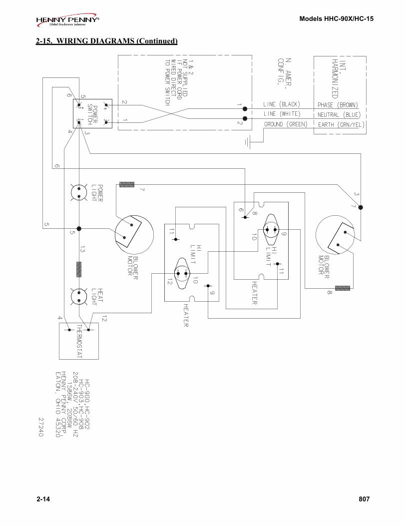
2-15. WIRING DIAGRAMS (Continued)

Models HHC-90X/HC-15
807 2-15
2-15. WIRING DIAGRAMS (Continued)

Models HHC-90X/HC-15
2-16 807
2-15. WIRING DIAGRAMS (Continued)

Models HHC-90X/HC-15
506 2-17
2-15. WIRING DIAGRAMS (Continued)

Models HHC-90X/HC-15
2-18 803
2-15. WIRING DIAGRAMS (Continued)

Models HHC-90X/HC-15
807 2-19
2-15. WIRING DIAGRAMS (Continued)

Models HHC-90X/HC-15
2-20 510
2-15. WIRING DIAGRAMS (Continued)

Models HHC-90X/HC-15
803 2-21
2-15. WIRING DIAGRAMS (Continued)

Models HHC-90X/HC-15
2-22 807
2-15. WIRING DIAGRAMS (Continued)
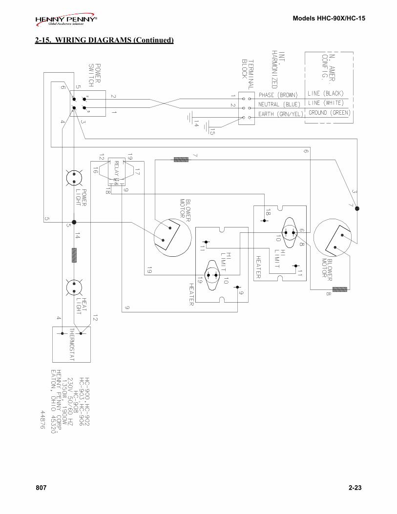
Models HHC-90X/HC-15
807 2-23
2-15. WIRING DIAGRAMS (Continued)

Models HHC-90X/HC-15
2-24 506
2-15. WIRING DIAGRAMS (Continued)

Models HHC-90X/HC-15
506 2-25
2-15. WIRING DIAGRAMS (Continued)

Models HHC-90X/HC-15
2-26 807

Models HHC-90X/HC-15
807 2-27

Models HHC-90X/HC-15
2-28 1209

Models HHC-90X/HC-15
510 2-29

Models HHC-90X/HC-15
2-30 510
HHC-900 EM & HC-15, 208-240V/50 or 60 Hz/1 Phase, Non-UL, Non-CE

Models HHC-90X/HC-15
510 2-31
HHC-900 CDT, 208-240V/50 or 60 Hz/1 Phase, Non-UL, Non-CE

Models HHC-90X/HC-15
LIMITED WARRANTY FOR HENNY PENNY EQUIPMENT
Subject to the following conditions, Henny Penny Corporation makes the following limited warranties to the original pur-chaser only for Henny Penny appliances and replacement parts:
NEW EQUIPMENT:Anypartofanewappliance,exceptbaskets,lamps,andfuses,whichprovestobedefectiveinmaterialorworkmanshipwithintwo(2)yearsfromdateoforiginalinstallation,willberepairedorreplacedwithoutchargeF.O.B.factory,Eaton,Ohio,orF.O.B.authorizeddistributor.Basketswillberepairedorreplacedforninety(90)days from date of original installation. Lamps and fuses are not covered under this Limited Warranty. To validate this warranty,theregistrationcardfortheappliancemustbemailedtoHennyPennywithinten(10)daysafterinstallation.
FILTER SYSTEM:Failureofanypartswithinafryerfiltersystemcausedbytheuseofthenon-OEMfiltersorotherunapprovedfiltersisnot covered under this Limited Warranty.
REPLACEMENT PARTS:Anyappliancereplacementpart,exceptlampsandfuses,whichprovestobedefectiveinmaterialorworkmanshipwithinninety(90)daysfromdateoforiginalinstallationwillberepairedorreplacedwithoutcharge F.O.B. factory, Eaton, Ohio, or F.O.B. authorized distributor.
Thewarrantyfornewequipmentcoverstherepairorreplacementofthedefectivepartandincludeslaborchargesandmaximummileagechargesof200milesroundtripforaperiodofone(1)yearfromthedateoforiginalinstallation.
The warranty for replacement parts covers only the repair or replacement of the defective part and does not include any laborchargesfortheremovalandinstallationofanyparts,travel,orotherexpensesincidentaltotherepairorreplacementofa part.
EXTENDED FRYPOT WARRANTY: Henny Penny will replace any frypot that fails due to manufacturing or workmanship issuesforaperiodofuptoseven(7)yearsfromdateofmanufacture.Thiswarrantyshallnotcoveranyfrypotthatfailsduetoany misuse or abuse, such as heating of the frypot without shortening.
0 TO 3 YEARS: During this time, any frypot that fails due to manufacturing or workmanship issues will be replaced at no charge for parts, labor, or freight. Henny Penny will either install a new frypot at no cost or provide a new or reconditioned replacement fryer at no cost.
3 TO 7 YEARS: During this time, any frypot that fails due to manufacturing or workmanship issues will be replaced at no charge for the frypot only. Any freight charges and labor costs to install the new frypot aswellasthecostofanyotherpartsreplaced,suchasinsulation,thermalsensors,highlimits,fittings,andhardware, will be the responsibility of the owner.
Any claim must be presented to either Henny Penny or the distributor from whom the appliance was purchased. No allow-ance will be granted for repairs made by anyone else without Henny Penny’s written consent. If damage occurs during shipping, notifythesenderatoncesothataclaimmaybefiled.
THEABOVELIMITEDWARRANTYSETSFORTHTHESOLEREMEDYAGAINSTHENNYPENNYFORANYBREACHOFWARRANTYOROTHERTERM.BUYERAGREESTHATNOOTHERREMEDY(INCLUDINGCLAIMSFORANYINCIDENTALORCONSEQUENTIALDAMAGES)SHALLBEAVAILABLE.
Theabovelimitedwarrantydoesnotapply(a)todamageresultingfromaccident,alteration,misuse,orabuse;(b)iftheequipment’sserialnumberisremovedordefaced;or(c)forlampsandfuses.THEABOVELIMITEDWARRANTYISEX-PRESSLY IN LIEU OF ALL OTHER WARRANTIES, EXPRESS OR IMPLIED, INCLUDING MERCHANTABILITY AND FITNESS, AND ALL OTHER WARRANTIES ARE EXCLUDED. HENNY PENNY NEITHER ASSUMES NOR AUTHO-RIZES ANY PERSON TO ASSUME FOR IT ANY OTHER OBLIGATION OR LIABILITY.
Revised 01/01/07
2-30 107

Models HHC-90X/HC-15
SECTION 3. PARTS INFORMATION
3-1. INTRODUCTION ThissectionidentifiesandliststhereplaceablepartsoftheHennyPenny Model HHC-900 heated holding cabinet.
3-2. GENUINE PARTS Use only genuine Henny Penny parts in your cabinet. Using a part oflesserqualityorsubstitutedesignmayresultincabinetdamageor personal injury.
3-3. HOW TO FIND PARTS TofinditemsyouwanttoorderfromthePartsList,proceed as follows:
1.Referringtotheillustrationinthissection,findthepartitem number of the part needed.
2. Find the item number in the parts list, which shows the Henny Penny part number, a description of the part, any model or usagelimitations,andthequantityofpartsused.
3-4. HOW TO ORDER Once the parts you want to order have been found in the Parts List, write down the following information:
Example:
Item number 44Part number 14635Description Power Switch
From the data plate list the following information:
Example: Product number HHC-900.0 Serial number 00179 Voltage120
803 3-1

Models HHC-90X/HC-15
3-4. HOW TO ORDER (Continued)
The following table has been provided as a sample format for you to use in preparing your spare parts orders. By providing all the entries, your distributor will be able to ensure the correct parts will be sent to you. Also, by prepayment your order will be expedited.
FROM PARTS LIST YOUR ORDER
Item Part Quantity Number Number Description Ordered Price Each Total
46 25183 Thermometer
ProductNo.HHC-900.0 SerialNo.00179 Voltage120
3-5. PRICES Your distributor has a priced parts list and will be glad to inform you of the cost of your parts order.
3-6. DELIVERY Commonly replaced items are stocked by your distributor and will be sent out when your order is received. Other parts will be ordered by your distributor from Henny Penny Corporation. Nor-mally, these will be sent to your distributor within three working days.
3-7. WARRANTY Allreplacementparts(exceptlampsandfuses)arewarrantedfor 90 days against manufacturing defects and workmanship. If damage occurs during shipping, notify the sender and the carrier atoncesothataclaimmaybeproperlyfiled.Refertowarrantyinthe front of this section for other rights and limitations.
Recommended replacement parts, stocked by your distributor, are indicated with √ in the parts lists. Please use care when order-ing recommended parts, because all voltages and variations are marked. Distributors should order parts based upon common voltagesandequipmentsoldintheirterritory.
3-2 106
3-8. RECOMMENDED SPARE PARTS FOR DISTRIBUTORS

Models HHC-90X/HC-15
104 3-3
Figure 3-1. Control Module Assembly - UL & CE Approved
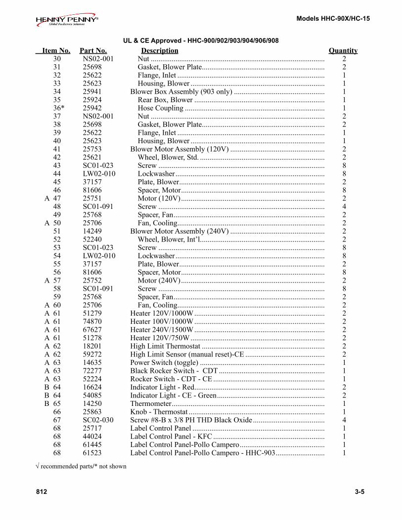
UL & CE Approved - HHC-900/902/903/904/906/908

Models HHC-90X/HC-15
Figure No. & Item No. Part No. Description Quantity 3-1 Control Module Assembly - UL & CE Approved 1 25704 Panel - Access ............................................................................... 1 1 51209 Panel -Access - C E ...................................................................... 1 2 SC01-053 Screw#8-32x1/2PHRHD ......................................................... 4 3 48993 Panel-Rear(208/240V)S/A ........................................................ 1 3 71092 Panel-Rear(120V)S/A .............................................................. 1 3 25944 Panel Rear S/A: HC-903 ............................................................... 1 3 28121 Panel-RearHHC-906;HHC-908 ................................................ 1 3 49018 Panel - Rear - CE .......................................................................... 1 4 EC04-002 Terminal Flag #10-10-12 Ga. ........................................................ 1 5 MS01-212 Cable#12/3,2,000W/120V .......................................................... 8 Ft. 5 MS01-175 Cable#14/3;1500W/120V&3000W/240V ................................ 8 Ft. 5 67390 PowerCordAssy.-Twist-120V/20A .......................................... 1 5 67472 PowerCordAssy.-125V,20Amp ............................................... 1 5 44857 Power Cord Assy. - 1.0MM - CE .................................................. 1 5 71119 Power Cord Assy. - 1.5MM - HHC-906 - CE ............................... 1 5 71120 PowerCordAssy.-Canada-120V/30A-RTAngle ..................... 1 5 68412 Power Cord Assy. - Canada - 208/240/20A .................................. 1 5 68413 Power Cord Assy. - 208/240/20A ................................................. 1 5 71384 PowerCordAssy.-Harmonized-Int’l.-240V ........................... 1 6 25765 Plug125V,20Amp;Usedon2000W/120V ................................. 1 6 25764 Plug125V,15Amp,Usedon1500W/120V ................................. 1 6 63943 Plug250V,20Amp;Usedon3000W/240V ................................. 1 6 28543 Plug-Twist-120V/20A ............................................................... 1 6 71717 Plug-120V,30Amp-RTAngle-Canada ................................... 1 7 SC01-010 Screw#6-32x112pHPHD ......................................................... 2 A 8 EF02-007 Fuse 15 Amp ................................................................................. 1 9 EF02-124 Connector - Cable 3/4 ................................................................... 1 10 SC02-023 Screw48-Bx3/8pHTHD ........................................................... 15 11 NS02-001 Nut#10-32HexKeps ................................................................... 1 A 12 EF02-006 Fuse Holder ................................................................................... 1 13 NS02005 Nut#6-32HexKeps ..................................................................... 2 14 EC01-010 Wire Nut 12-18 Ga ........................................................................ 2 15 76396 Top - Enclosure ............................................................................. 1 15 28153 Top HHC-906, HHC-908 .............................................................. 1 16 26225 Insulation - Cover ......................................................................... 1 17 SC02-041 Screw#8-18x7/16PHINDXTRNLTORX ............................... 18 18 25620 Seal ................................................................................................ 2 19 25670 Cradle ............................................................................................ 1 20 25624 Seal ................................................................................................ 2 21 25619 Gasket - Blower Outlet ................................................................. 2 22 25618 Gasket Retainer ............................................................................. 2 23 SC02-012 Screw#12-ABx3/8PhPHD ....................................................... 2 24 SC01-055 Screw#10-32x3/4HexHD ........................................................ 2 25 EF02-031 Clamp1/4x3/8” ........................................................................... 2 26 EF02-033 Clamp7/16x3/8” ......................................................................... 2 27 25627 Gasket ........................................................................................... 2 28 25872 BlowerBoxAssembly(903andallothers) .................................. 1 or 2 29 25616 Box,Blower .............................................................................. 1
3-4 812
√ recommended parts
UL & CE Approved - HHC-900/902/903/904/906/908
Models HHC-90X/HC-15
Item No. Part No. Description Quantity 30 NS02-001 Nut ............................................................................................ 2 31 25698 Gasket, Blower Plate ................................................................. 2 32 25622 Flange, Inlet .............................................................................. 1 33 25623 Housing, Blower ....................................................................... 1 34 25941 BlowerBoxAssembly(903only) ................................................ 1 35 25924 RearBox,Blower ..................................................................... 1 36* 25942 Hose Coupling .......................................................................... 1 37 NS02-001 Nut ............................................................................................ 2 38 25698 Gasket, Blower Plate ................................................................. 2 39 25622 Flange, Inlet .............................................................................. 1 40 25623 Housing, Blower ....................................................................... 1 41 25753 BlowerMotorAssembly(120V) .................................................. 2 42 25621 Wheel, Blower, Std. .................................................................. 2 43 SC01-023 Screw ........................................................................................ 8 44 LW02-010 Lockwasher ............................................................................... 8 45 37157 Plate, Blower ............................................................................. 2 46 81606 Spacer, Motor ............................................................................ 8 A 47 25751 Motor(120V) ............................................................................ 2 48 SC01-091 Screw ........................................................................................ 4 49 25768 Spacer, Fan ................................................................................ 2 A 50 25706 Fan, Cooling .............................................................................. 2 51 14249 BlowerMotorAssembly(240V) .................................................. 2 52 52240 Wheel, Blower, Int’l. ................................................................. 2 53 SC01-023 Screw ........................................................................................ 8 54 LW02-010 Lockwasher ............................................................................... 8 55 37157 Plate, Blower ............................................................................. 2 56 81606 Spacer, Motor ............................................................................ 8 A 57 25752 Motor(240V) ............................................................................ 2 58 SC01-091 Screw ........................................................................................ 8 59 25768 Spacer, Fan ................................................................................ 2 A 60 25706 Fan, Cooling .............................................................................. 2 A 61 51279 Heater120V/1000W ..................................................................... 2 A 61 74870 Heater100V/1000W ..................................................................... 2 A 61 67627 Heater240V/1500W ..................................................................... 2 A 61 51278 Heater120V/750W ....................................................................... 2 A 62 18201 High Limit Thermostat ................................................................. 2 A 62 59272 HighLimitSensor(manualreset)-CE .......................................... 2 A 63 14635 PowerSwitch(toggle) .................................................................. 1 A 63 72277 Black Rocker Switch - CDT ........................................................ 1 A 63 52224 Rocker Switch - CDT - CE ........................................................... 1 B 64 16624 Indicator Light - Red ..................................................................... 2 B 64 54085 Indicator Light - CE - Green ......................................................... 2 B 65 14250 Thermometer ................................................................................. 1 66 25863 Knob-Thermostat ........................................................................ 1 67 SC02-030 Screw#8-Bx3/8PHTHDBlackOxide ...................................... 4 68 25717 Label Control Panel ...................................................................... 1 68 44024 LabelControlPanel-KFC ........................................................... 1 68 61445 Label Control Panel-Pollo Campero ............................................. 1 68 61523 Label Control Panel-Pollo Campero - HHC-903 .......................... 1
√ recommended parts/* not shown
812 3-5
UL & CE Approved - HHC-900/902/903/904/906/908
Models HHC-90X/HC-15
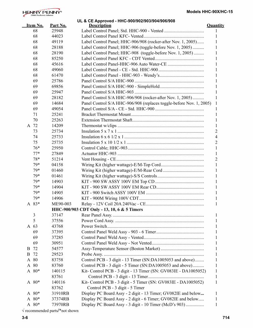
3-6 714
Item No. Part No. Description Quantity 68 25948 LabelControlPanel;Std.HHC-900-Vented ................................... 1 68 44023 LabelControlPanelKFC-Vented ..................................................... 1 68 49119 LabelControlPanel;HHC-906/908(rocker-afterNov.1,2005) ...... 1 68 28188 LabelControlPanel;HHC-906(toggle-beforeNov.1,2005) .......... 1 68 28190 LabelControlPanel;HHC-908(toggle-beforeNov.1,2005) ......... 1 68 85250 LabelControlPanelKFC-CDTVented ........................................... 1 68 45616 Label Control Panel-HHC-906 Auto Water-CE ................................ 1 68 49060 Label Control Panel - CE - Std. HHC-900 ........................................ 1 68 61470 Label Control Panel - HHC-903 - Wendy’s ....................................... 1 69 25786 Panel Control S/A HHC-900 ............................................................. 1 69 69856 Panel Control S/A HHC-900 - SimpleHold ....................................... 1 69 25947 Panel Control S/A HHC-903 ............................................................. 1 69 28182 PanelControlS/AHHC-906/908(rocker-afterNov.1,2005) .......... 1 69 14684 PanelControlS/AHHC-906/908(replacestoggle-beforeNov.1,2005) 1 69 49054 Panel Control S/A - CE - Std. HHC-900 ........................................... 1 71 25241 Bracket Thermostat Mount ................................................................ 1 70 25263 ExtensionThermostatShaft ............................................................... 1 A 72 14209 Thermostat w/clips ............................................................................ 1 73 25734 Insulation5x7x1 ............................................................................ 2 74 25733 Insulation6x61/2x1 ...................................................................... 4 75 25735 Insulation5x101/2x1 .................................................................... 2 76* 25950 ControlCable;HHC-903 ................................................................... 1 77* 27849 Actuator HHC-903 ............................................................................ 1 78* 51214 VentHousing-CE ............................................................................. 2 79* 04158 WiringKit(higherwattage)-E/M-TopCord ...................................... 1 79* 01460 WiringKit(higherwattage)-E/M-RearCord .................................... 1 79* 01461 WiringKit(higherwattage)-S/SControls ......................................... 1 79* 14903 KIT-900SWASSY100VEMTopCD ........................................... 1 79* 14904 KIT-900SWASSY100VEMRearCD .......................................... 1 79* 14905 KIT-900SwitchASSY100VEM ................................................... 1 79* 14906 KIT-900MWiring100VCDT ......................................................... 1 A 83* ME90-003 Relay-12VCoil20A240Vac-CE ................................................... 1 HHC-900/903 CDT Only - 13, 10, 6 & 5 Timers 3 37147 Rear Panel Assy. ................................................................................ 1 5 37556 Power Cord Assy. .............................................................................. 1 A 63 43768 Power Switch ..................................................................................... 1 69 37395 Control Panel Weld Assy - 903 - 6 Timer .......................................... 1 69 37285 ControlPanelWeldAssy-Vented ..................................................... 1 69 30951 ControlPanelWeldAssy-NotVented .............................................. 1 B 72 54577 Assy-TemperatureSensor(BostonMarket) ...................................... 1 B 72 29523 Probe Assy. ........................................................................................ 1 A 80 83758 ControlPCB-3digit-13Timer(SN:DA1005053andabove) ........ 1 A 80 83760 ControlPCB-3digit-5Timer(SN:DA1005053andabove) .......... 1 A 80* 140115 Kit-ControlPCB-3digit-13Timer(SN:GV083IE-DA1005052) 1 83761 Control PCB - 3 digit - 13 Timer ................................................. 1 A 80* 140116 Kit-ControlPCB-3digit-5Timer(SN:GV083IE-DA1005052) 1 83762 Control PCB - 3 digit - 5 Timer A 80* 31910RB DisplayPCBoardAssy-2digit-13Timer;GV082IEandbelow... 1 A 80* 37374RB DisplayPCBoardAssy-2digit-6Timer;GV082IEandbelow..... 1 A 80* 73970RB DisplayPCBoardAssy-3digit-10Timer(McD’s903) ................ 1√ recommended parts/*not shown
UL & CE Approved - HHC-900/902/903/904/906/908

Models HHC-90X/HC-15
Item No. Part No. Description Quantity
A 81* 78082RB ControlPCBoardAssy-3digit-10Timer(McD’s903) ........ 1 A 81* 73968RB ControlPCBoardAssy-2digit-5&13Timer;GV082IEandbelow 1 A 81* 70047RB ControlPCBoardAssy-2digit-6Timer;GV082IEandbelow ..... 1 B 82* 40500 ReplaceableBeeper-3Digit;GV083IEandabove ................... 1 B 82* 36210 ReplaceableBeeper-2Digit;GV082IEandbelow ................... 1 A 83* ME90-003 Relay12Vcoil ......................................................................... 1 A 84* 30978 Transformer115V ..................................................................... 1 A 84* 92406 Transformer240V ..................................................................... 1 98* 14871 KIT-903CVSRN5CDTto10CDT(FronttoBack) ............... 2 99* 14885 KIT-903CVSRN5CDTto10CDT(FronttoFront) .............. 2 100* 14774 KIT-900120VKFCPRGMTHERM ..................................... 1 101* 14775 KIT-900230/240VKFCPRGMTHERM .............................. 1 102* 14918 KIT-903CVSRN-STACKED ............................................... 1 HHC-900 CDT Decals 68 33874 Decal-KFCVented-3digit .................................................... 1 68 43952 Decal-KFCNonVented-3digit............................................. 1 68 30950 Decal - GM 900 - 3 digit ........................................................... 1 68 31901 Decal-903-6Timer-Vented-2digit .................................... 1 68 31931 Decal-903-6Timer-NonVented-2digit ............................ 1 68 52347 Decal - GM 903 - 5 Timer - 3 digit ........................................... 1 68 55180 Decal-13Timer-903-3digit(Churches) .............................. 1 68 61443 Decal - 900 Pollo Campero ....................................................... 1 HHC-900 CDT-5 Timers-KFC 68 43073 Control Panel Decal .................................................................. 1 A 80* 51117RB Display PC Board ..................................................................... 1 140115 Kit-HC90X13TimerReplacement .......................................... 1 140116 Kit-HC90X5TimerReplacement ............................................ 1 A 81* 39167RB --Control PC Board ................................................................... 1 B 82* 40500 Replaceable Beeper ................................................................... 1 A 84* 30978 Transformer ............................................................................... 1 Boston Market HHC-900 68 54511 Decal ......................................................................................... 1 A 72 54577 Temperature Sensor Assy. ......................................................... 1 A 81* 54571 PC Board Assy. ......................................................................... 1 A 83* 40645 Relay ......................................................................................... 1 A 84* 30978 Transformer ............................................................................... 1 SimpleHold - HHC-900 A 61 51278 Heater120V/750W ................................................................... 1 68 69894 Decal ......................................................................................... 1 A 72 29523 Temperature Sensor Assy. ......................................................... 1 A 81* 69843 PC Board Assy. ......................................................................... 1 A 83* 40645 Relay ......................................................................................... 1 A 84* 30978 Transformer ............................................................................... 1
714 3-7
√ recommended parts/*not shown
UL & CE Approved - HHC-900/902/903/904/906/908

Models HHC-90X/HC-15
C.E. Parts 5 44857 Power Cord Assy....................................................................... 1 A 63 52224 Rocker Switch - CDT - CE ....................................................... 1 A 63 43768 Power Switch - Plastic .............................................................. 1 68 49038 Decal - Control Panel - HHC-900 ............................................. 1 68 49060 Decal-ControlPanel-Vented-HHC-903 .................................. 1 68 49086 Decal-ControlPanel-KFC-HHC-900 ...................................... 1 68 49118 Decal-ControlPanel-w/Vent-HHC-906/908 ........................... 1 Vented Control Module 85* 48990 RearPanelStudweldAssy(Full)900 ....................................... 1 85* 25944 RrPnlStudweldAssy(1/3)903(SN:DA0506014&below) .. 1 85* 68859 RearPanelStudweldAssy(1/3)903(SN:DA0506015&up) . 1 85* 28123 Rear Panel Studweld Assy-906/908 .......................................... 1 86* 28155 Cable - E/M ............................................................................... 1 86* 25950 Cable - CDT .............................................................................. 1 87* 25964 Hose - Intake ............................................................................. 1 88* 25963 Hose-Exhaust .......................................................................... 1 89* 25977 Hose Clamp ............................................................................... 4 90* 25942 Coupling - Hose ........................................................................ 1 91* 25999 Control Panel Stud Assy ........................................................... 1 92* 38429 VentControlArm ...................................................................... 1 93* 38367 Knob-VentedModule .............................................................. 1 94* 27927 Spacer-SlideVent(SN:DA0506014&below) ...................... 1 94* 68574 Spacer-SlideVent(SN:DA0506015&above)....................... 1 95* 27828 Slide-Vent-Back(SN:DA0506014&below) ....................... 1 96* 28092 Slide-Vent-Blower-Box(SN:DA0506014&below) ......... 1 97* 25919 Slide-Vent(SN:DA0506014&below) .................................. 1 97* 68573 Slide-Vent(SN:DA0506015&above) .................................. 1
√ recommended parts/*not shown
Item No. Part No. Description Quantity
3-8 812
UL & CE Approved - HHC-900/902/903/904/906/908

Models HHC-90X/HC-15
908 3-9
Figure 3-2. Cabinet Assembly - UL & CE Approved
UL & CE Approved - HHC-900/902/903/904/906/908

Models HHC-90X/HC-15
3-10 912
Figure No. & Item No. Part No. Description Quantity
3-2 Cabinet Assembly - UL & CE Approved 1 ContactHP ControlModule120V,2,000W ................................................. 1 1 ContactHP ControlModule120V,1,500W,HHC-903 ............................... 1 1 ContactHP ControlModule120V,2,000W,HHC-906,HHC-908.............. 1 2 SC01-170 Screw#10-32x2-1/2PHPHD ................................................. 4 3 28816 Right Hand Top Door Assembly ............................................... 1 3 28817 Right Hand Bottom Door Assembly ......................................... 1 3 28818 Left Hand Top Door Assembly ................................................. 1 3 28819 Left Hand Bottom Door Assembly ........................................... 1 3 27033 Right Door Assembly, HHC-903 .............................................. 1 3 27034 Left Door Assembly, HHC-903 ................................................ 1 3 28158 Right Hand Top Door Assembly, HHC-906 ............................. 1 3 85644 Left Hand Top Door Assembly, HHC-906 ................................ 1 3 85645 Right Hand Bottom Door Assembly, HHC-906 ....................... 1 3 85646 Left Hand Bottom Door Assembly, HHC-906 .......................... 1 3 28166 Right Hand Door Assembly, HHC-908 .................................... 1 3 28168 Left Hand Door Assembly, HHC-908 ....................................... 1 4 14271 Kit-HHC-900Hinge ............................................................... 8 5a SC01-086 Screw#10-32x1 PH TH S ................................................. 16 5b SC01-225 Screw#10-32x3/4 PH TH S ............................................. 24 5c 27146 Cover - Hinge Pin - Chrome ............................................... 8 6 SC01-074 Screw#10-32x1/2PHTH ....................................................... 16 7a LW01-002 Lockwasher Split 1/4” ............................................................... 8 7b* WA01-013 Flat Washer 1/4” ........................................................................ 8 8a SC01-039 Screw1/4-20x1HexHead ...................................................... 8 8b SC01-193 Screw1/4-20x3/4”HexHead ................................................. 8 9a 27155 Caster5”(Seeitem52) ............................................................. 2 9b 40948 Caster-4”;Rigid(Seeitem51) .................................................. 2 9c 58139 Caster-3”Dia.;4”Height;Rigid(Seeitem50) ........................ 2 9d 18645 Caster 2-1/2” ............................................................................. 2 9e 68804 Caster 5” - CE ........................................................................... 2 9f 28170 Caster 5” Non-Swivel HHC-906, HHC-908 ............................. 2 9g 19004 Caster 2” .................................................................................... 4 9h 78671 Caster 1.5” - Swivel .................................................................. 4 10a 27154 Caster5”W/Brake(Seeitem52) .............................................. 2 10b 40947 Caster-4”;SwivelW/Brake(Seeitem51) ................................ 2 10c 58138 Caster-3”Dia.;4”Height;SwivelW/Brake(Seeitem50) ....... 2 10d 18646 Caster 3” W/Brake .................................................................... 2 10e 68803 Caster 5” W/Brake - CE ............................................................ 2 11 SC01-075 Screw#10-32x3/. PHT TH ................................................... 12 12 25695 Washer ....................................................................................... 12√ recommended parts/*not shown
UL & CE Approved - HHC-900/902/903/904/906/908

Models HHC-90X/HC-15
Item No. Part No. Description Quantity
13 25644 Spacer ........................................................................................ 12 14 25687 Retainer,HHC-900;HHC-903 ................................................. 8 & 4 14 28117 Retainer,HHC-906;HHC-908 ................................................. 8 & 4 15 SC02-041 Screw#8-18x7/16PHINDXTRNLTORX ........................... 24 16 25689 Retainer, HHC-900 ................................................................... 8 16 25690 Retainer, HHC-903 ................................................................... 4 17 NS01-008 Nut#8-32HexS ....................................................................... 10 18 LW02-006 Lockwasher Internal #8 S ......................................................... 10 19 SC01-053 Screw#8-32x1/2 PH RHD ...................................................... 10 B 20 25643 Gasket Door .............................................................................. 4 B 20 25793 Gasket - Door, HHC-903 .......................................................... 4 B 20 28147 Gasket - Door, HHC-906 .......................................................... 2 B 20 28143 Gasket - Door, HHC-908 .......................................................... 1 21 71478 WaterBoxAssemblywithHandle-HHC-903-FlipDoors .... 1 21 25879 WaterBoxAssemblywithHandle ............................................ 1 22 25707 WaterBoxandStudAssembly ........................................... 1 22 70381 WaterBoxandStudAssembly-HHC-903-FlipDoors .... 1 23 25646 Wiper................................................................................... 1 24 25685 Pull ...................................................................................... 1 25 LW02-005 Lockwasher Internal #10 .................................................... 2 26 NS03-030 Nut Acorn #10-32 ............................................................... 2 27 27895 Air Duct Assembly - Upper ...................................................... 2 27 42964 AirDuctAssembly-Upper-HHC-900K(SIB) .................... 2 27 52345 AirDuct-Upper-KFC-Int’l-CDT-15Tray ................................ 2 27 25957 Air Duct Assembly - HHC-903 ................................................. 2 27 70387 Air Duct Assembly - HHC-903 - Flip Doors ............................ 2 27 70032 Air Duct Assembly - HHC-903 - Pollo Campero ..................... 2 27 34928 Air Duct Assembly- Upper - Boston Mkt. ................................ 2 27 55181 Air Duct Assembly- Upper- Churches ...................................... 2 27 55087 Air Duct Assembly-Upper-Wendy’s #10 .................................. 2 27 28129 Air Duct-Upper ONLY-NO SLIDES HHC-906 (uses28133slides) 2 27 34519 AirDuct-UpperONLY-NOSLIDES-KnottsBerry-HC-906(uses34536slides) 2 28 55088 Air Duct Assembly-Lower-Wendy’s #10 .................................. 2 28 55084 Air Duct Assembly-Wendy’s-903 Plast. ................................... 2 28 27811 Air Duct Assembly - Lower ...................................................... 2 28 55187 Air Duct Assembly- Lower-Churches....................................... 2 28 34929 Air Duct Assembly-Lower-Boston Mkt. ................................... 2 28 52346 AirDuct-Lower-KFC-Int’l-CDT-15Tray ................................. 2 28 42965 AirDuctAssembly-LowerHHC-900K(SIB) ......................... 2 28 28130 AirDuctONLY-NOSLIDES-LowerHHC-906(uses28133slides) 2 28 34517 AirDuct-LowerONLY-NOSLIDES-KnottsBerry-HC-906(uses34536slides) 2 28 28128 AirDuctONLY-NOSLIDES-HHC-908(uses28133slides) . 2 28 34553 AirDuctONLY-NOSLIDES-KnottsBerry-HC-908(uses34536slides) 2
914 3-11√ recommended parts
UL & CE Approved - HHC-900/902/903/904/906/908

Models HHC-90X/HC-15
Item No. Part No. Description Quantity
29 25696 Hanger ....................................................................................... 16 30 SC02-023 Screw#8-Bx3/8PHTHDS .................................................... 8 31 14272 Latch/ScrewKit ........................................................................ 4 32 SC01-186 Screw#10-32x1-3/4 PH .................................................... 16 33 34536 Slides ONLY - HHC-906, HHC-908 ........................................ 22 & 8 34 28133 Slides ONLY, HHC-906, HHC-908 .......................................... 22 & 8 35 34544 Air Duct Assembly Complete - HHC-908, ............................... 2 35 34545 Air Duct Assembly Complete - Lower - HHC-906 ................. 2 35 34550 Air Duct Assembly Complete - Upper - HHC-906 .................. 2 36 14647 Kit-LegAdjustable-4inch(Setof4legs) ............................. 1 36 68946 Legs - Adjustable - 4 inch ................................................... 4 37 68937 Weld Assy - Mtg. Plate & Leg - 4 inch ............................... 4 38 26120 Foot - Adjustable ................................................................. 4 39 27149 Stop - Door ................................................................................ 4 39 34949 Door Stop - Boston Mkt. .......................................................... 4 40* 27146 Chrome Hinge Cover ................................................................ 1 41* 27912 Handle, HHC-906, HHC-908 ................................................... 1 42* 27939 Brkt. Handle, HHC-906, HHC-908 .......................................... 2 43* 58116 HingePlate(TapBar)HHC-900 ............................................... 4 44*58274 HingePlate(TapBar)HHC-903 ........................... 4 45* 03182 Worktop - HHC-903.................................................................. 1 46* 56179 Worktop - HHC-908.................................................................. 1 47* 14853 Kit-903UndercounterCVSRN ............................................... 1 48* 58047 Insulation - Side ........................................................................ 2 49* 03559 Accessory - Storage Bin ............................................................ 1 50* 86832 3”CasterSet(Incluidesitems7a,7b,8b,9b,&10b) ............... 1 51* 86833 4”CasterSet(Incluidesitems7a,7b,8b,9c,&10c) ............... 1 52* 86850 5”CasterSet(Incluidesitems7a,8a,9a,&10a) ..................... 1 Glass Doors Only 3 54353 GlassDoorAssembly-1/3size(LH) ........................................ 1 3 54352 GlassDoorAssembly-1/3size(RH) ........................................ 1 -- 30517* Nut - Glass Retainer .................................................................. 4 3 59257 Glass Door Assy.-Left, Top ....................................................... 1 3 59258 Glass Door Assy.-Left, Bottom ................................................. 1 3 59260 Glass Door Assy.-Right, Top ..................................................... 1 3 59261 Glass Door Assy.-Right, Bottom ............................................... 1 3 76480 GlassDoorAssy.-1/2size(McD’s) ......................................... 1 Church’s HHC-903 3 54353 GlassDoorAssembly-1/3size(LH) ........................... 1 3 54352 GlassDoorAssembly-1/3size(RH) ....................................... 1
3-12 510
* not shown
UL & CE Approved - HHC-900/902/903/904/906/908

Models HHC-90X/HC-15
Figure 3-3. Flip-Up Door Assemblies (HHC-903 - SN: DA0511040 & Above)
908 3-13
20
UL & CE Approved - HHC-900/902/903/904/906/908

Models HHC-90X/HC-15
•HHC-903’s(1/3-size)withSN:DA0511039 & below, SN required. •HHC-900(full-size)withSN:DA0511039&below,no parts available. Complete door assembly must be ordered.Figure No. Qty per Door& Item No. Part No. Description 900 903 3-3 Flip-Up Door Assemblies 1 71309 Assy - Door - Flip - RH - Full Size .................................................. 1 - 1 71403 Assy - Door - Flip - LH - Full Size ................................................... 1 - 1 71466 Assy - Door - Flip - RH - 1/3 Size (DA0511040&Above) .............. - 1 1 71467 Assy - Door - Flip - LH - 1/3 Size (DA0511040&Above) .............. - 1 2 75544-004 Panel - Flip Door - 9.562 HGT .......................................................... 1 - 3 75544-003 Panel - Flip Door - 6.860 HGT .......................................................... 1 - 4 75544-005 Panel - Flip Door - 6.735 HGT .......................................................... 1 - 5 75544-001 Panel - Upper Flip Door - 1/3 Size .................................................... - 1 6 75544-002 Panel - Lower Flip Door - 8.108 HGT .............................................. - 1 7 71308 Assy - Hinge - Panel - Door - Flip..................................................... 3 2 8 71067 Rod - Flip Door ........................................................................... 3 2 9 71316 Spring - Flip Door ....................................................................... 3 2 10 70768 Cam - Flip Door - RH .................................................................. 3 2 10 70769 Cam - Flip Door - LH .................................................................. 3 2 11 73320 Extrusion-FlipDoor .................................................................. 3 2 12 SC01-032 Screw-#8-32x5/8PH100FHDSS ................................................ 6 4 13 LW02-006 Lockwasher - Internal - #8 S ............................................................. 6 4 14 NS03-024 Nut - #8-32 Low Crown Acorn - B P ................................................ 6 4 15 14272 Kit-HC-900DoorHandle ................................................................ 1 1 16 SC01-186 Screw-#10-32x1-3/4PHFHDSS ........................................... 4 4 17 14271 Kit-HC-900DoorHinge .................................................................. 2 2 18 SC01-086 Screw-#8-32x1PHFHDS ...................................................... 4 4 19 71310 Weld Assy - Flip Door Frame - RH - Full Size ................................. 1 - 19 71404 Weld Assy - Flip Door Frame - LH - Full Size.................................. 1 - 19 71056 Weld Assy - Flip Door Frame - RH - 1/3 Size ................................... - 1 19 71057 Weld Assy - Flip Door Frame - LH - 1/3 Size ................................... - 1 20 03557 Accessory - Flip Door Tray ............................................................... - 1
3-14 908
UL & CE Approved - HHC-900/902/903/904/906/908

Models HHC-90X/HC-15
510 3-15
Figure 3-4. Control Module Assembly - Non-UL, Non-CE
Non-UL & Non-CE Approved - HHC-900 EM, HHC-900 CDT, & HC-15

Models HHC-90X/HC-15
Figure No. & Item No. Part No. Description Quantity 3-4 Control Module Assembly - Non-UL, Non-CE 1 72312 Panel-AccessLouvers(HHC-900EM&HC-15) .................... 1 1 80890 Panel-AccessLouvers(HHC-900CDT) .................................. 1 2 SC02-023 Screw#8-32x1/2PHRHD ...................................................... 4 3 28029 Panel-Rear(208/240V)S/A(HHC-900EM) ........................... 1 3 72404 Panel-Rear(120V)S/A(HHC-900CDT) ................................ 1 3 72317 PanelRearS/A(HC-15) ............................................................ 1 4 EC04-004 Terminal Flag #10-10-12 Ga. .................................................... 1 5 31584 PowerCordAssy(HHC-900CDT) ........................................... 1 5 71384 PowerCordAssy-240V(HHC-900EM&HC-15) ................... 1 5 72532 ASSY-PWRCORD120/30ATWISTLK ................................ 1 7 SC01-010 Screw#6-32x112pHPHD ..................................................... 2 A8 EF02-007 Fuse 15 Amp ............................................................................. 1 9 49778 Connector - Cable 3/4 ............................................................... 1 10 SC02-023 Screw48-Bx3/8pHTHD ....................................................... 15 11 NS02-001 Nut#10-32HexKeps ............................................................... 1 A12 EF02-006 Fuse Holder ............................................................................... 1 13 NS02005 Nut#6-32HexKeps ................................................................. 2 14 EC01-010 Wire Nut 12-18 Ga .................................................................... 2 15 72305 Top-Enclosure(HHC-900EM&HC-15) ................................ 1 15 84607 Top-Enclosure(HHC-900CDT) .............................................. 1 16 26225 Insulation - Cover ..................................................................... 1 17 SC02-041 Screw#8-18x7/16PHINDXTRNLTORX ........................... 18 18 25620 Seal ............................................................................................ 2 19 25670 Cradle ........................................................................................ 1 20 25624 Seal ............................................................................................ 2 21 25619 Gasket - Blower Outlet ............................................................. 2 22 25618 Gasket Retainer ......................................................................... 2 23 SC02-041 Screw#8-18x7/16PHINDXTRNLTORX ........................... 2 24 SC01-074 Screw#10-32x3/4HexHD ..................................................... 2 25 EF02-031 Clamp1/4x3/8”(HC-15) ........................................................ 2 26 EF02-003 Wire Tie ..................................................................................... 4 27 25627 Gasket ....................................................................................... 2 28 72915 BlowerBoxAssembly(HHC-900EM&CDT) ....................... 2 29 72914 Box,Blower(HHC-900EM&CDT) .................................. 1 30 NS02-001 Nut......................................................................................... 2 31 25698 Gasket,BlowerPlate(HHC-900EM&CDT) ..................... 1 32 25622 Flange,Inlet(HHC-900EM&CDT) ................................... 1 33 25623 Housing,Blower(HHC-900EM&CDT) ............................ 1 34 87097 BlowerBoxAssembly(HC-15) ................................................ 2 35 72914 RearBox,Blower(HC-15) .................................................. 1 37 NS02-001 Nut......................................................................................... 2 38 25698 Gasket,BlowerPlate(HC-15) ............................................. 2 39 25622 Flange,Inlet(HC-15) ........................................................... 1 40 25623 Housing,Blower(HC-15) ..................................................... 1
√ recommended parts
3-16 613
Non-UL & Non-CE Approved - HHC-900 EM, HHC-900 CDT, & HC-15

Models HHC-90X/HC-15
Item No. Part No. Description Quantity
51 14249 BlowerMotorAssembly(240V) .............................................. 2 52 52240 Wheel, Blower, Int’l. ............................................................. 1 53 SC01-023 Screw ..................................................................................... 4 54 LW02-010 Lockwasher ........................................................................... 4 55 37157 Plate, Blower ......................................................................... 1 56 81606 Spacer, Motor ........................................................................ 4 A 57 25752 Motor(240V) ........................................................................ 1 58 SC01-091 Screw ..................................................................................... 4 59 25768 Spacer, Fan ............................................................................ 1 A 60 25706 Fan, Cooling .......................................................................... 1 A 61 51279 Heater120V/1000W ................................................................. 2 A 62 18201 High Limit Thermostat.............................................................. 2 A 63 95230 PowerSwitch(HHC-900EM&HC-15) ................................... 1 A 63 72277 BlackRockerSwitch(HHC-900CDT) ..................................... 1 B 64 16624 IndicatorLight-Red(HHC-900EM&HC-15) ...................... 2 A 65 14250 Thermometer(HHC-900EM&HC-15) ................................. 1 66 25863 Knob-Thermostat .................................................................... 1 67 SC02-030 Screw#8-Bx3/8PHTHDBlackOxide .................................. 4 68 44204 Decal-Control(HHC-900EM) .................................................. 1 68 85249 Decal-Control(HHC-900CDT) ................................................ 1 68 87065 Decal-Control(HC-15) ............................................................. 1 69 72440 PanelControlS/A(HHC-900EM&HC-15) ............................ 1 69 81307 PanelControlS/A(HHC-900CDT) .......................................... 1 71 25241 Bracket Thermostat Mount ....................................................... 1 A 72 14209 Thermostat w/clips .................................................................... 1 73 25734 Insulation5x7x1 .................................................................... 2 74 25733 Insulation6x61/2x1 ............................................................. 4 75 25735 Insulation5x101/2x1 ........................................................... 2 A 80* 83758 Control&DisplayPCBAssy-13Timer(HHC-900CDT) ...... 1 A 83* ME90-009 Relay240Vcoil,30A(HHC-900CDT) .................................... 1 A 84* 92406 Transformer240V(HHC-900CDT) ......................................... 1 103* 27870 Insulator, Fan Motor ................................................................. 1 √ recommended parts/* not shown
613 3-17
Non-UL & Non-CE Approved - HHC-900 EM, HHC-900 CDT, & HC-15

Models HHC-90X/HC-15
3-18 510
Figure 3-5. Cabinet Assembly - Non-UL, Non-CE
Non-UL & Non-CE Approved - HHC-900 EM, HHC-900 CDT, & HC-15

Models HHC-90X/HC-15
Figure No. & Item No. Part No. Description Quantity 3-5 Cabinet Assembly - Non-UL, Non-CE 2 SC01-170 Screw#10-32x2-1/2PHPHD ..................................................... 4 2* LW02-004 Lockwasher ................................................................................... 4 2* WA01-022 Flat Washer ................................................................................... 2 2* 37151 Spacer(HHC-900EM&HC-15) ................................................. 2 3 59257 Glass Door Assy.-Left, Top ........................................................... 1 3 59258 Glass Door Assy.-Left, Bottom ..................................................... 1 3 59260 Glass Door Assy.-Right, Top......................................................... 1 3 59261 Glass Door Assy.-Right, Bottom ................................................... 1 4 14271 Kit-Hinge ................................................................................... 8 5a SC01-086 Screw#10-32x1PHTHS .................................................... 16 5b SC01-225 Screw#10-32x3/4PHTHS ................................................. 24 5c 27146 Cover - Hinge Pin - Chrome ......................................................... 8 6 SC01-074 Screw#10-32x1/2PHTH ........................................................... 16 7 LW01-002 Lockwasher Split 1/4” .................................................................. 8 8 SC01-104 Screw1/4-20x1-1/2”HexHead .................................................. 8 9 72365 Caster 5” ...................................................................................... 2 10 72364 Caster 5” W/Brake ........................................................................ 2 11 SC01-075 Screw#10-32x3/.PHTTH ...................................................... 12 12 25695 Washer ........................................................................................... 12 13 25644 Spacer ............................................................................................ 12 14 25687 Retainer ......................................................................................... 8 & 4 15 SC02-041 Screw#8-18x7/16PHINDXTRNLTORX ............................... 24 16 25689 Retainer ......................................................................................... 8 17 NS01-008 Nut#8-32HexS ........................................................................... 10 18 LW02-006 Lockwasher Internal #8 S ............................................................. 10 19 27944 Cap Screw #8 ................................................................................ 10 B 20 25643 Gasket Door .................................................................................. 4 21 72405 WaterBoxAssemblywithHandle ................................................ 1 22 72406 WaterBoxandStudAssembly ............................................... 1 23 25646 Wiper ...................................................................................... 1 24 25685 Pull .......................................................................................... 1 25 LW02-005 Lockwasher Internal #10 ........................................................ 2 26 NS03-030 Nut Acorn #10-32 ................................................................... 2 27 27895 AirDuctAssembly-Upper(HHC-900CDT) .............................. 2 27 52345 AirDuct-Upper-15Tray(HHC-900EM&HC-15) ..................... 2 28 27811 AirDuctAssembly-Lower(HHC-900CDT) .............................. 2 28 52346 AirDuct-Lower-15Tray(HHC-900EM&HC-15) ...................... 2 31 14272 Latch/ScrewKit ............................................................................ 4 32 SC01-186 Screw#10-32x1-3/4PH ....................................................... 16 39 27149 Stop-Door(HHC-900EM&HHC-900CDT) ............................ 4 48* 58047 Insulation - Side ............................................................................ 1 53* 72366 Plate-Caster(HHC-900EM) ....................................................... 4
√ recommended parts / * not shown
812 3-19
Non-UL & Non-CE Approved - HHC-900 EM, HHC-900 CDT, & HC-15