Embed Size (px)
Citation preview

Henny PennyExpress Profit Center
Model EPC-2Model EPC-3Model EPC-4
OPERATOR’S MANUALREGISTER WARRANTY ONLINE AT WWW.HENNYPENNY.COM
(Translated Documents Available On CD within Manual)


Model EPC-2, EPC-3 & EPC-4
FM05-049-E6-2-10
LIMITED WARRANTY FOR HENNY PENNY EQUIPMENT
Subject to the following conditions, Henny Penny Corporation makes the following limited warranties to the originalpurchaser only for Henny Penny appliances and replacement parts:
NEW EQUIPMENT: Any part of a new appliance, except baskets, lamps, and fuses, which proves to be defective inmaterial or workmanship within two (2) years from date of original installation, will be repaired or replaced withoutcharge F.O.B. factory, Eaton, Ohio, or F.O.B. authorized distributor. Baskets will be repaired or replaced for ninety (90)days from date of original installation. Lamps and fuses are not covered under this Limited Warranty. To validate thiswarranty, the registration card for the appliance must be mailed to Henny Penny within ten (10) days after installation.
FILTER SYSTEM: Failure of any parts within a fryer filter system caused by the use of the non-OEM filters orother unapproved filters is not covered under this Limited Warranty.
REPLACEMENT PARTS: Any appliance replacement part, except lamps and fuses, which proves to be defective inmaterial or workmanship within ninety (90) days from date of original installation will be repaired or replaced withoutcharge F.O.B. factory, Eaton, Ohio, or F.O.B. authorized distributor.
The warranty for new equipment covers the repair or replacement of the defective part and includes labor charges andmaximum mileage charges of 200 miles round trip for a period of one (1) year from the date of original installation.
The warranty for replacement parts covers only the repair or replacement of the defective part and does not include anylabor charges for the removal and installation of any parts, travel, or other expenses incidental to the repair or replacement ofa part.
EXTENDED FRYPOT WARRANTY: Henny Penny will replace any frypot that fails due to manufacturing or workmanshipissues for a period of up to seven (7) years from date of manufacture. This warranty shall not cover any frypot that fails due toany misuse or abuse, such as heating of the frypot without shortening.
0 TO 3 YEARS: During this time, any frypot that fails due to manufacturing or workmanship issues willbe replaced at no charge for parts, labor, or freight. Henny Penny will either install a new frypot at no cost orprovide a new or reconditioned replacement fryer at no cost.
3 TO 7 YEARS: During this time, any frypot that fails due to manufacturing or workmanship issues willbe replaced at no charge for the frypot only. Any freight charges and labor costs to install the new frypot aswell as the cost of any other parts replaced, such as insulation, thermal sensors, high limits, fittings, andhardware, will be the responsibility of the owner.
Any claim must be presented to either Henny Penny or the distributor from whom the appliance was purchased. Noallowance will be granted for repairs made by anyone else without Henny Penny’s written consent. If damage occurs duringshipping, notify the sender at once so that a claim may be filed.
THE ABOVE LIMITED WARRANTY SETS FORTH THE SOLE REMEDY AGAINST HENNY PENNY FOR ANY BREACHOF WARRANTY OR OTHER TERM. BUYER AGREES THAT NO OTHER REMEDY (INCLUDING CLAIMS FOR ANY INCI-DENTAL OR CONSEQUENTIAL DAMAGES) SHALL BE AVAILABLE.
The above limited warranty does not apply (a) to damage resulting from accident, alteration, misuse, or abuse; (b) if theequipment’s serial number is removed or defaced; or (c) for lamps and fuses. THE ABOVE LIMITED WARRANTY IS EX-PRESSLY IN LIEU OF ALL OTHER WARRANTIES, EXPRESS OR IMPLIED, INCLUDING MERCHANTABILITY AND FIT-NESS, AND ALL OTHER WARRANTIES ARE EXCLUDED. HENNY PENNY NEITHER ASSUMES NOR AUTHORIZES ANYPERSON TO ASSUME FOR IT ANY OTHER OBLIGATION OR LIABILITY.
Revised 01/01/07

Model EPC-2, EPC-3 & EPC-4
TABLE OF CONTENTS
Section Page
Section 1. INTRODUCTION1-1. Heated Express Cabinet ................................................................................... 1-11-2. Features ........................................................................................................... 1-11-3. Proper Care ..................................................................................................... 1-21-4. Assistance ........................................................................................................ 1-21-5. Safety ............................................................................................................... 1-2
Section 2. INSTALLATION2-1. Introduction ...................................................................................................... 2-12-2. Unpacking ........................................................................................................ 2-12-3. Location ........................................................................................................... 2-22-4. Cabinet Dimensions .......................................................................................... 2-32-5. Electrical Connection ........................................................................................ 2-6
Section 3. OPERATION3-1. Introduction ...................................................................................................... 3-13-2. Operating Controls ........................................................................................... 3-13-3. Start-Up ........................................................................................................... 3-33-4. Operation with Product ..................................................................................... 3-43-5. Cleaning Procedures ......................................................................................... 3-43-6. Special Program Mode ..................................................................................... 3-6
Section 4. TROUBLESHOOTING4-1. Troubleshooting Guide ...................................................................................... 4-14-2. Error Codes ..................................................................................................... 4-1
GLOSSARY .................................................................................................................................. G-1
Distributor Lists - Domestic and International
i 608
Model EPC-2, EPC-3 & EPC-4
SECTION 1. INTRODUCTION
408 1-1
1-1. HEATED EXPRESSCABINET
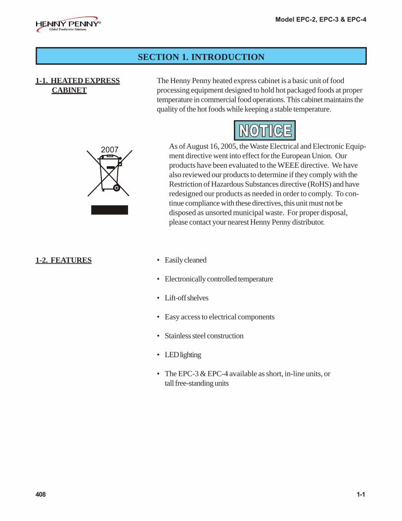
The Henny Penny heated express cabinet is a basic unit of foodprocessing equipment designed to hold hot packaged foods at propertemperature in commercial food operations. This cabinet maintains thequality of the hot foods while keeping a stable temperature.
As of August 16, 2005, the Waste Electrical and Electronic Equip-ment directive went into effect for the European Union. Ourproducts have been evaluated to the WEEE directive. We havealso reviewed our products to determine if they comply with theRestriction of Hazardous Substances directive (RoHS) and haveredesigned our products as needed in order to comply. To con-tinue compliance with these directives, this unit must not bedisposed as unsorted municipal waste. For proper disposal,please contact your nearest Henny Penny distributor.
• Easily cleaned
• Electronically controlled temperature
• Lift-off shelves
• Easy access to electrical components
• Stainless steel construction
• LED lighting
• The EPC-3 & EPC-4 available as short, in-line units, ortall free-standing units
1-2. FEATURES

Model EPC-2, EPC-3 & EPC-4
1-3. PROPER CARE
1-2 707
As in any unit of food service equipment, the Henny Penny heatedexpress cabinet does require care and maintenance. Requirementsfor the maintenance and cleaning are contained in this manual andmust become a regular part of the operation of the unit at all times.
1-4. ASSISTANCE Should you require outside assistance, just call your local independentHenny Penny distributor in your area, or call Henny Penny Corp.1-800-417-8405 toll free or 1-937-456-8405.
1-5. SAFETY The only way to insure safe operation of the Henny Penny heatedexpress cabinet is to fully understand the proper installation, operation,and maintenance procedures. The instructions in this manual have beenprepared to aid you in learning the proper procedures. Where informa-tion is of particular importance or is safety related, the wordsNOTICE, CAUTION, or WARNING are used. Their usage isdescribed below.
SAFETY ALERT SYMBOL is used with DANGER, WARNING, orCAUTION which indicates a personal injury type hazard.
NOTICE is used to highlight especially important information.
CAUTION used without the safety alert symbol indicatesa potentially hazardous situation which, if not avoided, mayresult in property damage.
CAUTION used with the safety alert symbol indicates a poten-tially hazardous situation which, if not avoided, may result inminor or moderate injury.
WARNING indicates a potentially hazardous situation which, ifnot avoided, could result in death or serious injury.
Model EPC-2, EPC-3 & EPC-4
2-1. INTRODUCTION This section provides the installation instructions for the Henny Pennyheated express cabinet.
Installation of this unit should be performed only by a qualifiedservice technician.
Do not puncture the skin of the unit with drills or screws ascomponent damage or electrical shock could result.
2-2. UNPACKING The Henny Penny heated express cabinet has been tested, inspected,and expertly packed to insure arrival at its destination in the bestpossible condition. The unit has been bolted to wooden skid. Allitems have been packed and taped inside of the unit. The unit is thenpacked inside a triple wall corrugated carton with sufficient padding towithstand normal shipping treatment.
Any shipping damages should be noted in the presence of thedelivery agent and signed prior to his or her departure.
To remove the Henny Penny cabinet from the carton, you should:
1. Carefully cut banding straps.
2. Open flaps of carton and remove packing.
3. Remove carton from unit.
4. Remove unit from packaging.
SECTION 2. INSTALLATION
707 2-1
Model EPC-2, EPC-3 & EPC-4
2-2 707
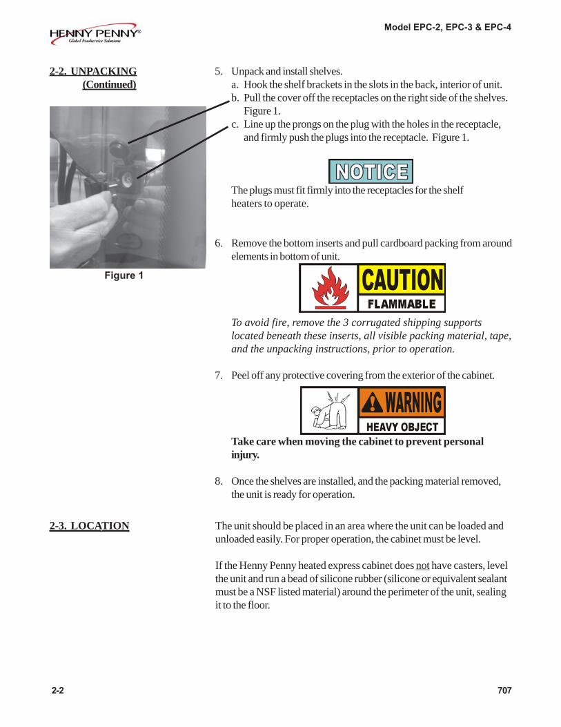
5. Unpack and install shelves.a. Hook the shelf brackets in the slots in the back, interior of unit.b. Pull the cover off the receptacles on the right side of the shelves.
Figure 1.c. Line up the prongs on the plug with the holes in the receptacle,
and firmly push the plugs into the receptacle. Figure 1.
The plugs must fit firmly into the receptacles for the shelfheaters to operate.
6. Remove the bottom inserts and pull cardboard packing from aroundelements in bottom of unit.
To avoid fire, remove the 3 corrugated shipping supportslocated beneath these inserts, all visible packing material, tape,and the unpacking instructions, prior to operation.
7. Peel off any protective covering from the exterior of the cabinet.
Take care when moving the cabinet to prevent personalinjury.
8. Once the shelves are installed, and the packing material removed,the unit is ready for operation.
2-2. UNPACKING(Continued)
Figure 1
2-3. LOCATION The unit should be placed in an area where the unit can be loaded andunloaded easily. For proper operation, the cabinet must be level.
If the Henny Penny heated express cabinet does not have casters, levelthe unit and run a bead of silicone rubber (silicone or equivalent sealantmust be a NSF listed material) around the perimeter of the unit, sealingit to the floor.

Model EPC-2, EPC-3 & EPC-4
408 2-3
2-4. CABINET DIMENSIONS
EPC-2

Model EPC-2, EPC-3 & EPC-4
2-4. CABINET DIMENSIONS (Continued)
EPC-3In-Line(short)
EPC-3(tall)
2-4 408

Model EPC-2, EPC-3 & EPC-4
2-4. CABINET DIMENSIONS (Continued)
EPC-4In-Line (short)
EPC-4(tall)
408 2-5

Model EPC-2, EPC-3 & EPC-4
The EPC-2 is available from the factory as a 120 or 208 VAC,1 phase, 60 hz. unit, or a 230V, 1 phase, 50 hz. unit.
The EPC-3 & EPC-4 is available from the factory as a 208 or240 VAC, 3 phase, 60 hz. unit, or a 400V, 3 phase, 50/60 hz. unit.
The data plate, located on the rear, interior of the unit, specifies thecorrect electrical supply. The unit requires a grounded receptaclewith a separate electrical line protected by a fuse or circuit breakerof the proper rating.
To avoid electrical shock, the cabinet must be adequatelyand safely grounded (earthed) according to local electri-cal codes, and this appliance must be equipped with anexternal circuit breaker which will disconnect all un-grounded (unearthed) conductors. The main powerswitch on this appliance does not disconnect all lineconductors.
(FOR EQUIPMENT WITH CE MARK ONLY!)To prevent electric shock hazard this appliance must bebonded to other appliances or touchable metal surfaces inclose proximity to this appliance with an equipotentialbonding conductor. This appliance is equipped with anequipotential lug for this purpose. The equipotential lug ismarked with the following symbol
2-5. ELECTRICALCONNECTION
2-6 1109

Model EPC-2, EPC-3 & EPC-4
Model Number Ph Volts Watts AmpsEPC-2 1 120 2268 18.9EPC-2 1 208 2147 10.3EPC-2 1 230 2093 9.1
EPC-4-Short 1 208 4584 22.0EPC-4-Short 3 208 4584 19.0EPC-4-Short 1 240 4600 20.0EPC-4-Short 3 240 4600 16.5EPC-4-Short 3 400 4595 7.5
EPC-4-Tall (3 shelf) 1 208 5134 24.7EPC-4-Tall (3 shelf) 3 208 5134 21.1EPC-4-Tall (3 shelf) 1 240 5149 22.3EPC-4-Tall (3 shelf) 3 240 5149 18.3EPC-4-Tall (3 shelf) 3 400 5145 8.8
EPC-4-Tall (4 shelf) 1 208 5684 27.3EPC-4-Tall (4 shelf) 3 208 5684 23.4EPC-4-Tall (4 shelf) 1 240 5700 24.5EPC-4-Tall (4 shelf) 3 240 5700 20.2EPC-4-Tall (4 shelf) 3 400 5700 8.8
Model Number Ph Volts Watts Amps- - - - -- - - - -
EPC-3-Short 1 208 3570 17.2EPC-3-Short 3 208 3570 14.8EPC-3-Short 1 240 3578 15.7EPC-3-Short 3 240 3578 12.8EPC-3-Short 3 400 3575 8.5
EPC-3-Tall (3 shelf) 1 208 4010 19.3EPC-3-Tall (3 shelf) 3 208 4010 16.5EPC-3-Tall (3 shelf) 1 240 4018 17.5EPC-3-Tall (3 shelf) 3 240 4018 14.3EPC-3-Tall (3 shelf) 3 400 4016 10.4
EPC-3-Tall (4 shelf) 1 208 4450 21.4EPC-3-Tall (4 shelf) 3 208 4450 18.3EPC-3-Tall (4 shelf) 1 240 4458 19.4EPC-3-Tall (4 shelf) 3 240 4458 15.9EPC-3-Tall (4 shelf) 3 400 4456 10.4
2-5. ELECTRICALCONNECTION
(Continued)
The tables below shows electrical ratings for the EPC-2, EPC-3 & EPC-4
1109 2-7

Model EPC-2, EPC-3 & EPC-4
3-1 408
3-1. INTRODUCTION This section provides explanations of all controls, alongwith operating procedures and daily maintenance. Read theIntroduction, Installation and Operation Sections beforeoperating the unit.
To access the controls, the bottom, front panel must beremoved by pulling out on one corner of the panel andunsnapping it from the clips.
3-2. OPERATING CONTROLS Refer to control diagrams on next page. Item Description FunctionNo.not Power Switch A rocker switch that sends electrical current to the operating
shown components and lights when turned on
1 Digital Display Shows the cabinet temperature, error codes and the selectionsin the Program Modes
2 Press to set the base shelf heat value and to toggle through theProgram Mode
Lights when the heat is on for that shelf3
Press and hold to set the shelf heat value. The bold line indicatesthe shelf being preset.
The first 2 shelf buttons are also used in the Special ProgramMode to turn on and off the heat outputs for each shelf
4 Used to set the heat values of the shelves and base; press andhold, while turning on power switch to enter the Special ProgramMode; used in Special Program Mode to turn off and on heatoutputs
SECTION 3. OPERATION

Model EPC-2, EPC-3 & EPC-4
408 3-2
3-2. OPERATING CONTROLS (Continued)
Short, In-line Units Tall, 3 shelf Units
Tall, 4 shelf units
12
34
12
34
2 1
34

Model EPC-2, EPC-3 & EPC-4
3-3 608
3-3. START UP
Before using the heated express cabinet, thoroughly clean the unitas described in the Cleaning Procedures Section of this manual.
1. Turn the power switch to the ON position.
2. Press and hold and use to set the heat value of the
base shelf. It can be set from “OFF” to a maximum of “10”.
The upper heat settings read 1, 2, 3, etc. 1 meaning the heat is on10% of the time, 10 meaning the heat is on 100% of the time.
If “LOC” shows on the display when trying to set the heat value,this means the controls are locked and the settings cannot bechanged until unlocked in the Special Program Mode.
3. Press and hold each shelf button and use to set the heatvalue to each corresponding shelf.These can be set from “OFF” to a maximum of “10”. Use thediagram below the buttons to find which button controls whichshelf. Ex: Press and hold to set the middle shelf heatvalue.
*Recommended settings to hold prepackaged whole chickens at asafe temperature for up to 4 hours:
EPC-2 - A heat value setting of 10 for all shelvesEPC-3 & EPC-4 - A heat value setting of 9 - top 2 shelves
settings of 8 - lower shelves & deckSettings for other products may differ.
It is also recommended to lock the controls once the settings areprogrammed (see Specail Program Mode) to ensure the settingsaren’t changed by unauthorized personnel.
4. Allow unit to preheat for about 30 minutes, and then prepackagedfood products can now be placed on each shelf.
*Up to four hour holding times when the following ideal holding conditions are met:- Ambient temperatures ranging anywhere between 70° to 74°F (21° to 23°C)- Merchandiser holds 3.0 to 3.5 lb. (1.36 – 1.59 kg) chickens in domes [Pactiv CNC-6007]- Shelf heat is set per recommendation in the Operations Manual- Merchandiser is operated at rated voltage- Chicken enters the merchandiser between 180° to 190°F (82° to 88°C)
Model EPC-2, EPC-3 & EPC-4
608 3-4
3-4. OPERATION WITHPRODUCT
1. Place the hot, prepackaged product on each of the shelves.
All shelf surfaces are hot! Burns could result!
To assure quality product, stacking prepackaged product is notrecommended.
Also, to hold prepackaged whole chickens at safe temperaturefor up to 4 hours, the product temperature must be above180o F (82o C) when placed in the unit
2. Serve the product first that has been in the cabinet the longest.
1. Turn power switch to OFF
2. Disconnect the electrical supply to the cabinet.
To avoid burns, allow the unit to cool before cleaning.
3. Remove all product from the cabinet.
4. Wipe down each shelf with a damp cloth, soap and water.
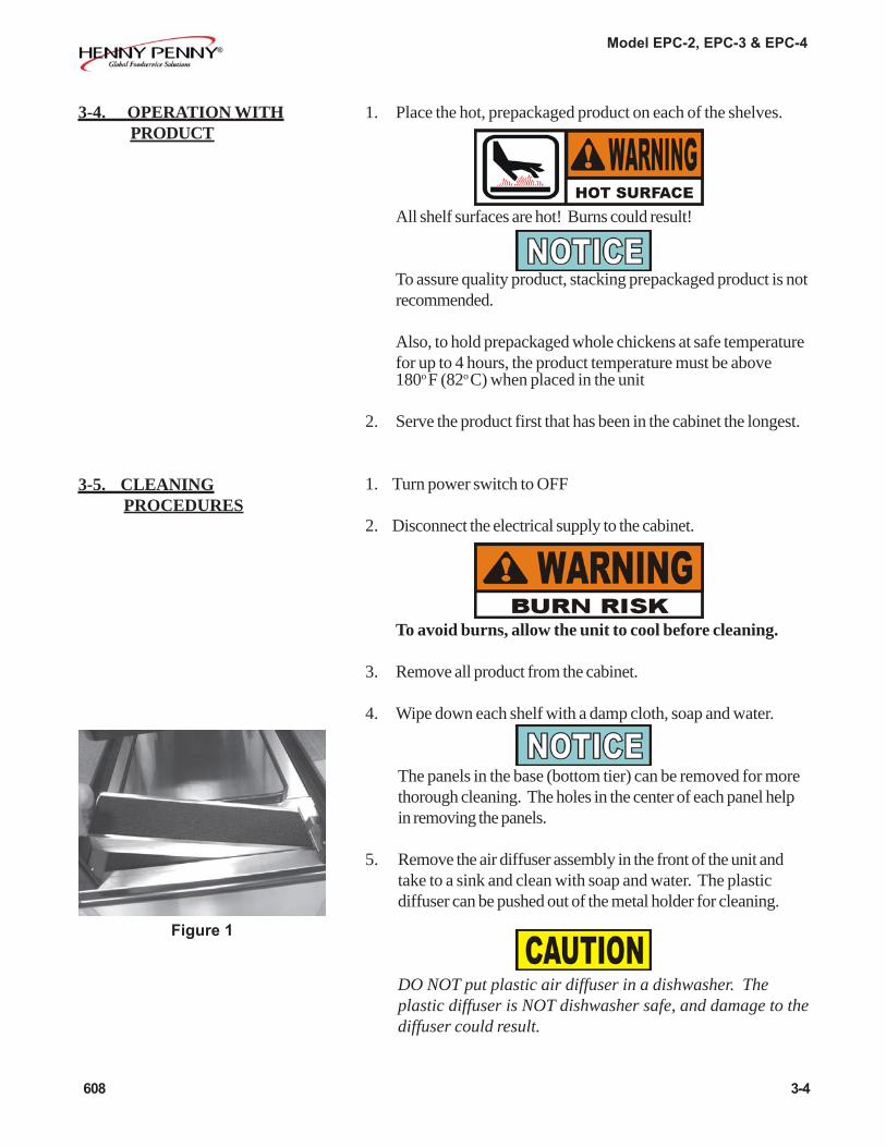
The panels in the base (bottom tier) can be removed for morethorough cleaning. The holes in the center of each panel helpin removing the panels.
5. Remove the air diffuser assembly in the front of the unit andtake to a sink and clean with soap and water. The plasticdiffuser can be pushed out of the metal holder for cleaning.
DO NOT put plastic air diffuser in a dishwasher. Theplastic diffuser is NOT dishwasher safe, and damage to thediffuser could result.
Figure 1
3-5. CLEANING PROCEDURES

Model EPC-2, EPC-3 & EPC-4
6. Clean the exterior of the cabinet with a damp cloth.
For stubborn spots on the black top cap, Henny Pennyrecommends the Foaming Degreaser - Part no. 12226 and forthe side glass, Glass Cleaner - Part no. 12227.
See your local distributor for details.
7. Clean the side glass with non-streaking liquid glass cleaner anda soft cloth.. Do not use abrasive cleaners.
Do not use steel wool, other abrasive cleaners orcleaners/sanitizers containing chlorine, bromine, iodineor ammonia chemicals, as these will deteriorate thestainless steel material, shorten the life of the unit, andscratch the black coating on the side glass.
Do not use a water jet (pressure sprayer) to cleanthe unit, or component failure could result.
Do not use alcohol or alcohol-based cleaners (suchas sanitizers) on the plastic shelves or LED lenscovers, or damage to these components could result.
8. Replace diffuser properly into unit. Looking at the under-sideof the diffuser assembly, the plastic diffuser must go towardsthe inside of the unit. Figure 2.
To prevent foreign objects from entering the air duct andto avoid the risk of fire, DO NOT operate unit withoutdiffuser in place.
9. Allow the unit to thoroughly dry before adding more product.
3-5. CLEANING PROCEDURES
(Continued)
3-5 610
Figure 2
towards interior of unit
Model EPC-2, EPC-3 & EPC-4
3-6. SPECIAL PROGRAM MODE
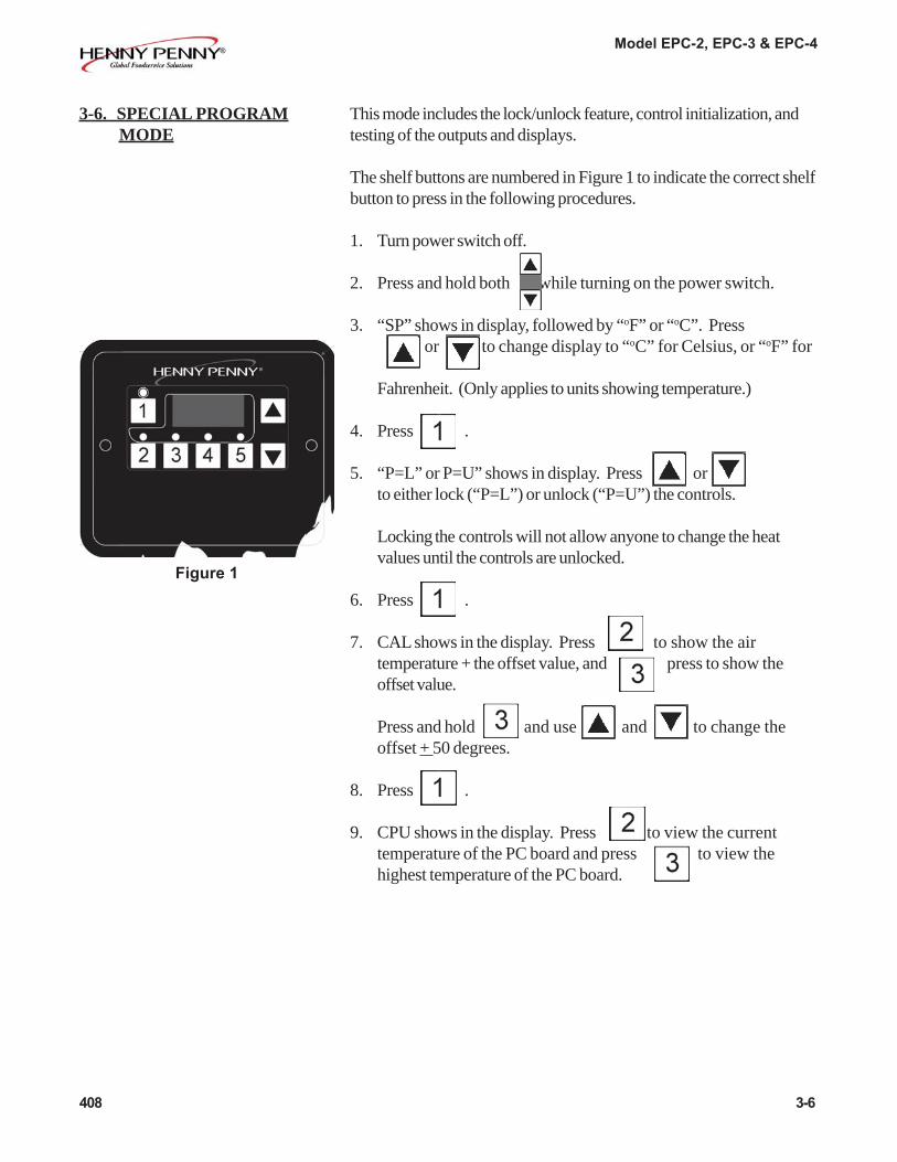
This mode includes the lock/unlock feature, control initialization, andtesting of the outputs and displays.
The shelf buttons are numbered in Figure 1 to indicate the correct shelfbutton to press in the following procedures.
1. Turn power switch off.
2. Press and hold both while turning on the power switch.
3. “SP” shows in display, followed by “oF” or “oC”. Press or to change display to “oC” for Celsius, or “oF” for
Fahrenheit. (Only applies to units showing temperature.)
4. Press .
5. “P=L” or P=U” shows in display. Press orto either lock (“P=L”) or unlock (“P=U”) the controls.
Locking the controls will not allow anyone to change the heatvalues until the controls are unlocked.
6. Press .
7. CAL shows in the display. Press to show the airtemperature + the offset value, and press to show theoffset value.
Press and hold and use and to change theoffset + 50 degrees.
8. Press .
9. CPU shows in the display. Press to view the currenttemperature of the PC board and press to view thehighest temperature of the PC board.
408 3-6
Figure 1

Model EPC-2, EPC-3 & EPC-4
10. “OP” shows in the display. Press and release the shelf buttonsto turn off and on the heat outputs for each shelf. Press andrelease to turn off and on the base heat outputs. Press
to turn off and on all displays and outputs.
11. Press .
12. “In” shows in the display. Press and hold or tore-initialize the controls, which sets all heat settings to “OFF”,or to factory set parameters. “In3”, “In2”, “In1” shows in thedisplay, followed by “In-”, “SyS”, indicating the initialization iscomplete.
13. Press .
14. “CE=y” or “CE=n” shows in the display. Use andto toggle between CE=y and CE=n. If controls are set toCE=y, then the display shows the current air temperature duringoperation.
If controls are set to CE=n, then the display shows “ON”during operation.
9. Press and hold to exit Special Program Mode.
Press and hold at any time to exit the Special ProgramMode, or if no buttons are pressed for 1 minute, controls auto-matically exits Special Program Mode.
3-6. SPECIAL PROGRAM MODE (Continued)
3-7 408

Model EPC-2, EPC-3 & EPC-4
Problem Cause Correction
Product not • Heat value of shelf not high enough • Set higher heat value in controlsholdingtemperature • Product not hot when placed in • Place prepackaged hot food in
cabinet cabinet
With power switch • Open Circuit • Check to see that unit is plugged in.on, unit iscompletely • Check breaker or fuse at supplyinoperative box(NO POWER)
Shelf won’t heat • Shelf not plugged into receptacle • Check that the shelf plug is firmlyproperly pushed into receptacle, in the
interior of the cabinet
807 4-1
SECTION 4. TROUBLESHOOTING
4-1. TROUBLESHOOTING GUIDE
4-2. ERROR CODES
DISPLAY CAUSE PANEL BOARD CORRECTION
“E04” Control board Turn unit off and back on; if display shows “E04”,overheating the control board is getting too hot; make sure unit is not
overheating
“E41” Memory scrambled Turn unit off and back on; if “E41” still shows on display,have PC board intitialized; if “E41” persists replace thecontrol board
“E06” Air temperature too hot Turn switch to OFF position, then turn switch back to ON;probe open if display shows “E06”, the temperature probeshould be checked
Controsl set CE=y Unit does not have a temperature probe and the controls mustin Special Program Mode be set to CE=n, in Special Program Mode

Model EPC-2, EPC-3 & EPC-4
G L O S S A R YHENNY PENNY HOLDING CABINETS
air temperature probe a round device located inside the cabinet that measures the inside airtemperature and sends that information to the control panel
air ducts channels attached to the sides, of the inside of the unit, that directs the hotair towards the bottom of the unit; usually has tray supports attached tothem
concentration ring assembly a metal assembly located in the water pan in the bottom of the unit thathelps keep an even humidity level inside the cabinet
clean water pan setpoint a preset temperature at which a sensor warns the operator that the water panhas excessive lime deposits
control panel the components that control the operating systems of the unit; the panel islocated on the top front surface of the cabinet
deliming agent a cleaner used to remove lime deposits in the water pan
drain valve a device that lets the water drain from the water pan into a shallow pan onthe floor; the valve should be closed while the unit is in use if humidity isdesired
float switch a device that senses low water levels in the water pan
food probe a sensor located outside the cabinet that, when inserted into the product,communicates the temperature of the product to the control panel
food probe receptacle the connection where the food probe is inserted in order to communicatewith the control panel
humidity sensor a device that measures the percentage of humidity inside the cabinet during use
humidity setting a preset moisture level at which the cabinet operates; this setting isprogrammed at the factory but can be changed in the field
LED an electronic light on the control panel
minimum holding temperature the lowest temperature at which a food product can be safely held forhuman consumption
module the removable top part of the cabinet that contains all of the operating system
out of water trip point a preset temperature at which a sensor warns the operator that the waterpan needs refilled
parameters a preset group of setpoints designed for holding specific food products atcertain temperature and humidity levels
power switch the ON/OFF switch that sends electricity to the unit’s operating systems;this switch does not disconnect the electrical power from the wall to the unit
G-1 707
Model EPC-2, EPC-3 & EPC-4
pressure sprayer a device that shoots a stream of water under pressure; this device shouldNOT be used to clean a holding cabinet
probe clip a metal holder that attaches to the outside of the control panel to hold thefood probe when not in use; the clip is an optional accessory
product load capacity the highest recommended number of pounds/kilograms of food product thatcan be safely held in the cabinet
proof function a program used for allowing bread to rise
relative humidity the humidity level outside the cabinet
setpoint a preset temperature or humidity; the setpoint is a programmable feature
system initialization a programming process that resets factory settings
temperature setting a preset temperature up to which the cabinet will heat; this setting isprogrammed at the factory but can be changed in the field
tray support guides, attached to air ducts, for trays of product to be held in the unit
vent activation switch an automatic control that opens and closes the vent on the rear of thecabinet to maintain the preset humidity level
vented panels openings on the cabinet that allow air access on the sides and rear of themodule
water fill line the line marked on the inside of the water pan that shows the maximumwater level to prevent overflow onto the floor
water heater sensor a part in the water heater that sends a message to the controls when thewater pan is limed up or empty
water jet a device that shoots a stream of water under pressure; this type of deviceshould NOT be used to clean a holding cabinet
water pan the area in the cabinet that holds water for creating humidity inside thecabinet
707 G-2

*FM05-049-6* Henny Penny Corp., Eaton, Ohio 45320, Revised 6-2-10
Henny Penny Corporation P.O.Box 60 Eaton,OH 45320 1-937-456-8400 1-937-456-8402 Fax Toll free in USA 1-800-417-8417 1-800-417-8434 Fax www.hennypenny.com