Embed Size (px)
Citation preview

TI902P/00/EN/05.10
Technical Information
Pressure transducer UC2Customer-specific pressure transducer
Individual solutions for your measuring tasks
Application
Pressure transducer e.g. for use in medical and
laboratory-specific measuring technology, shipbuilding
and hydrostatic level measurement.
Your benefits
Dry capacitive ceramic sensor
• Basic ceramic material Aluminum oxide ceramic
Al2O3
(Measuring cells 1 bar purity 99,7 %)
(Measuring cells 2 bar purity 96 %)
- high overload resistance
- long-term stability
- corrosion-resistant
• Finely graduated measuring ranges:
0 to 200 mbar to 0 to 20 bar gauge pressure or
absolute pressure
• Special measuring ranges available on request
e.g. 0 to 100 mbar gauge pressure
• Small physical size from Ø21.9 mm
• Flexibly adapted to customer-specific
requirements
• Housing made from various materials
• Various seal materials
• Output signal 0.5 to 4.5 V or 4 to 20 mA
Pressure Transducer UC2
2 Endress+Hauser
Table of contents
Function and system design. . . . . . . . . . . . . . . . . . . . . 3
Measuring principle . . . . . . . . . . . . . . . . . . . . . . . . . . . . . . . . . . . 3
Input . . . . . . . . . . . . . . . . . . . . . . . . . . . . . . . . . . . . . . 3
Measured variable . . . . . . . . . . . . . . . . . . . . . . . . . . . . . . . . . . . . 3
Measuring range . . . . . . . . . . . . . . . . . . . . . . . . . . . . . . . . . . . . . . 3
Output . . . . . . . . . . . . . . . . . . . . . . . . . . . . . . . . . . . . . 3
Output signal . . . . . . . . . . . . . . . . . . . . . . . . . . . . . . . . . . . . . . . 3
Load . . . . . . . . . . . . . . . . . . . . . . . . . . . . . . . . . . . . . . . . . . . . . . 3
Power supply. . . . . . . . . . . . . . . . . . . . . . . . . . . . . . . . 4
Electrical connection . . . . . . . . . . . . . . . . . . . . . . . . . . . . . . . . . . 4
Supply voltage . . . . . . . . . . . . . . . . . . . . . . . . . . . . . . . . . . . . . . . 5
Current consumption . . . . . . . . . . . . . . . . . . . . . . . . . . . . . . . . . . 5
Performance characteristics. . . . . . . . . . . . . . . . . . . . . 6
Reference operating
conditions . . . . . . . . . . . . . . . . . . . . . . . . . . . . . . . . . . . . . . . . . . 6
Zero point deviation . . . . . . . . . . . . . . . . . . . . . . . . . . . . . . . . . . . 6
Span deviation . . . . . . . . . . . . . . . . . . . . . . . . . . . . . . . . . . . . . . . 6
Maximum measured error . . . . . . . . . . . . . . . . . . . . . . . . . . . . . . 6
Rise time (T90) . . . . . . . . . . . . . . . . . . . . . . . . . . . . . . . . . . . . . . 6
Settling time (T99) . . . . . . . . . . . . . . . . . . . . . . . . . . . . . . . . . . . . 6
Long-term stability . . . . . . . . . . . . . . . . . . . . . . . . . . . . . . . . . . . . 6
Thermal change of the zero output and the output span within the
compensated temperature range . . . . . . . . . . . . . . . . . . . . . . . . . . 6
Thermal span change within the compensated temperature range
6
Operating conditions (installation) . . . . . . . . . . . . . . . 7
Orientation . . . . . . . . . . . . . . . . . . . . . . . . . . . . . . . . . . . . . . . . . 7
Operating conditions: Environment. . . . . . . . . . . . . . . 7
Ambient temperature range . . . . . . . . . . . . . . . . . . . . . . . . . . . . . 7
Storage temperature . . . . . . . . . . . . . . . . . . . . . . . . . . . . . . . . . . . 7
Degree of protection . . . . . . . . . . . . . . . . . . . . . . . . . . . . . . . . . . . 7
Climate class . . . . . . . . . . . . . . . . . . . . . . . . . . . . . . . . . . . . . . . . 7
Shock resistance . . . . . . . . . . . . . . . . . . . . . . . . . . . . . . . . . . . . . . 7
Electromagnetic
compatibility . . . . . . . . . . . . . . . . . . . . . . . . . . . . . . . . . . . . . . . . 7
Operating conditions (process) . . . . . . . . . . . . . . . . . . 7
Process temperature limits . . . . . . . . . . . . . . . . . . . . . . . . . . . . . . 7
Overload resistance . . . . . . . . . . . . . . . . . . . . . . . . . . . . . . . . . . . 7
Vacuum resistance . . . . . . . . . . . . . . . . . . . . . . . . . . . . . . . . . . . . 7
Mechanical construction . . . . . . . . . . . . . . . . . . . . . . . 8
Dimensions of the
basic modules . . . . . . . . . . . . . . . . . . . . . . . . . . . . . . . . . . . . . . . . 8
Material . . . . . . . . . . . . . . . . . . . . . . . . . . . . . . . . . . . . . . . . . . . . 9
Certificates and approvals . . . . . . . . . . . . . . . . . . . . . 10
CE mark . . . . . . . . . . . . . . . . . . . . . . . . . . . . . . . . . . . . . . . . . . 10
Pressure Equipment Directive (PED) . . . . . . . . . . . . . . . . . . . . . . 10
External standards and guidelines . . . . . . . . . . . . . . . . . . . . . . . . 10
Ordering information. . . . . . . . . . . . . . . . . . . . . . . . . 11
Pressure transducer UC2 . . . . . . . . . . . . . . . . . . . . . . . . . . . . . . 11
Additional documentation . . . . . . . . . . . . . . . . . . . . . 11
Operating instructions . . . . . . . . . . . . . . . . . . . . . . . . . . . . . . . . 11
Safety instructions . . . . . . . . . . . . . . . . . . . . . . . . . . . . . . . . . . . 11

Pressure Transducer UC2
Endress+Hauser 3
Function and system design
Measuring principle A capacitive ceramic sensor element is at the core of the UC2 transducer.
Its Al2O3 basic material is ceramic that is highly resistant against many aggressive gases and liquids. Two
cylindrical ceramic components (diaphragm and meter body) are bonded to form a high-strength, hermetically
sealed pressure sensor element. With absolute pressure sensors, the vacuum of 3.0 x 10⁻⁶ mbar created in the
production process between the process isolating diaphragm and the meter body remains permanently. This
permits pressure measurements relative to the vacuum. With gauge pressure sensors, the back of the process
isolating diaphragm is vented, i.e. this sensor measures the gauge pressure relative to the atmospheric pressure.
Electrically, the sensor element represents a plate capacitor whose capacitance change is the dimension for the
pressure change. The capacitive measuring process satisfies the highest requirements concerning resolution and
reproducibility.
Together with the hysteresis-free behavior of the material Al2O3 , it is the basis for the excellent specifications
of the transducer. In addition, the sensor element is a dry measuring cell, i.e. there is no separating diaphragm
or filling fluid which could influence the measurement.
A further advantage of the capacitive ceramic sensor is its high overload resistance. After removal of the
overload, the process isolating diaphragm returns to the initial position without any damage or hysteresis.
P01-UC2xxxxx-15-xx-xx-en-000
Input
Measured variable Gauge pressure or absolute pressure
Measuring range • Gauge pressure measurement: 0.2 to 20 bar
• Absolute pressure measurement: 0.2 to 20 bar
• Special measuring ranges available on request (e.g. 0 to 100 mbar absolut pressure)
See also "Ordering information" chapter ä 11.
Output
Output signal • Voltage output 0.5 to 4.5 V ratiometric
• Current output 4 to 20 mA
Load • Voltage output: 10 k or 300 pF
• Current output: RB = (US-12 V)/0.02 A (US = supply voltage)
Gauge pressure cell
Absolute pressure cell
Pressure
Pressure
Atmospheric pressure
Cp electrode
Brazing preform
Counter electrode
Substrate
Diaphragm
Cv electrode
Pressure Transducer UC2
4 Endress+Hauser
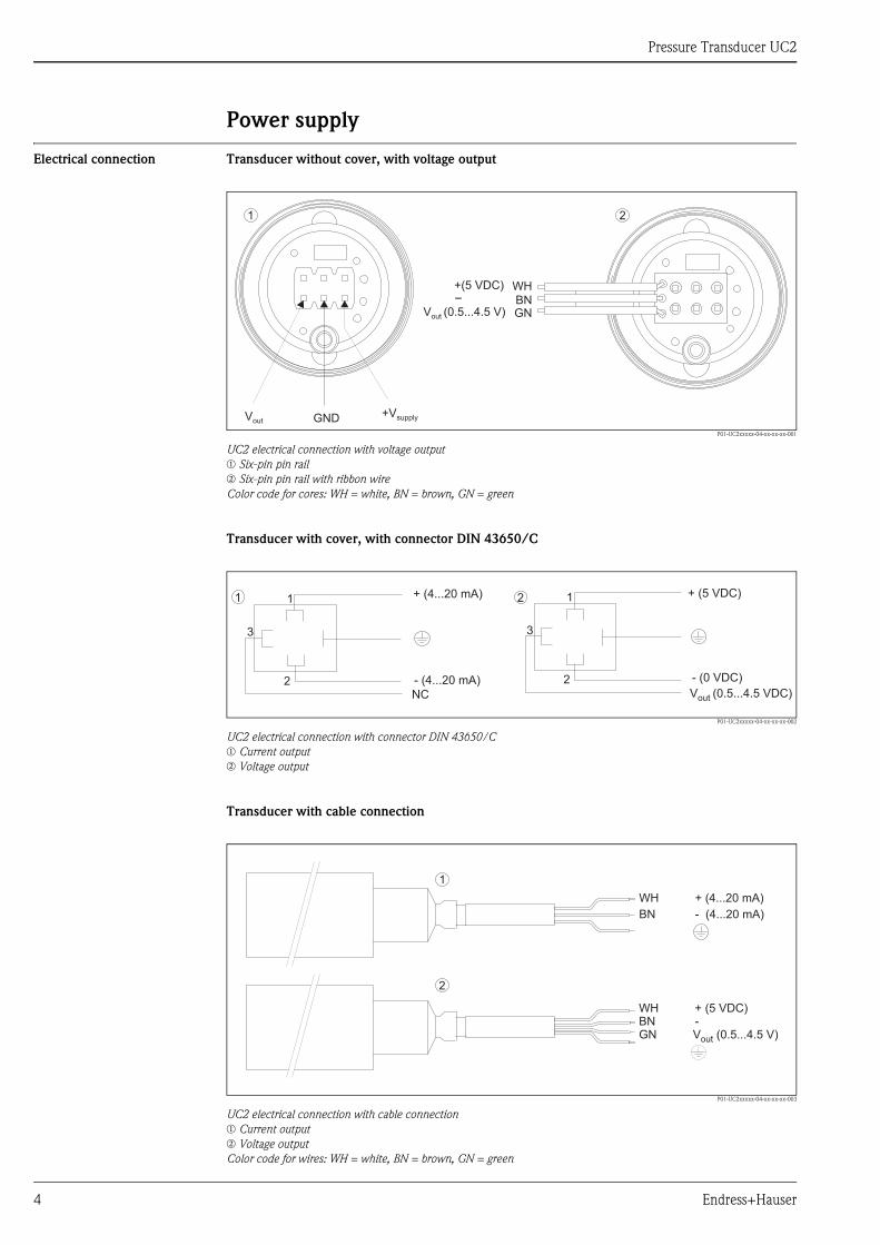
Power supply
Electrical connection Transducer without cover, with voltage output
P01-UC2xxxxx-04-xx-xx-xx-001
UC2 electrical connection with voltage outputm Six-pin pin railn Six-pin pin rail with ribbon wireColor code for cores: WH = white, BN = brown, GN = green
Transducer with cover, with connector DIN 43650/C
P01-UC2xxxxx-04-xx-xx-xx-002
UC2 electrical connection with connector DIN 43650/Cm Current outputn Voltage output
Transducer with cable connection
P01-UC2xxxxx-04-xx-xx-xx-003
UC2 electrical connection with cable connection m Current outputn Voltage outputColor code for wires: WH = white, BN = brown, GN = green
GND +VsupplyVout
1
+(5 VDC)-
V (0.5...4.5 V)out
WHBNGN
2
+ (4...20 mA)
- (4...20 mA)
NC
1 1
2 2
3 3
+ (5 VDC)
- (0 VDC)
V (0.5...4.5 VDC)out
1 2
WH + (4...20 mA)
BN - (4...20 mA)
WH + (5 VDC)BN -GN V (0.5...4.5 V)out
2
1

Pressure Transducer UC2
Endress+Hauser 5
Supply voltage • Voltage output: 4.5 to 5.5 V DC stabilized
Ratiometric signal: proportional effect on lower range-value and span
No effect on linearity and temperature compensation
• Current output: 12 to 30 V DC
The permitted voltage range is limited for devices with an explosion protection certificate. Observe the
related Safety Instructions XA513P.
Current consumption • Voltage output: max. 2 mA with a supply voltage of 5 V, with reverse polarity protection
• Current output: max. 23 mA, with reverse polarity protection

Pressure Transducer UC2
6 Endress+Hauser
Performance characteristics
Reference operating
conditions
As per DIN IEC 60770
Tu = 25 °C (77 °F), humidity 45 to 75 %, ambient air pressure 860 to 1060 mbar,
compensated temperature range: -20 to 80 °C
Zero point deviation
Span deviation
Maximum measured error Non-linearity + hysteresis + non-reproducibility: max. ± 0.25 % of span
Rise time (T90) Approx. 5 ms
Settling time (T99) Max. 10 ms
Long-term stability Max. 0.15 % of span per year
Thermal change of the zero
output within the
compensated temperature
range
Thermal span change within
the compensated temperature
range
Voltage output: max. ± 0.5 % of span. With measuring ranges < 0.4 bar, the value increases to ± 0.8 % of span.
With extended specification ± 1 % of span
Current output: max. ± 1 %. With extended specification ± 1.25 % of span
Voltage output Current output
Max. ±1 % of span Max. ±0.3 % of span
With extended specification and small measuring ranges <0.3 bar, max. ±0.5 % of span.
Voltage output Current output
Max. ±1 % of span Max. ±0,3 % of span
With extended specification and small measuring ranges <0.3 bar, max. ±0.5 % of span.
Voltage output Current output
Max. ±0,75 % of span Max. ±1 % of span
With extended specification ±1 % of span. With extended specification ±1.25 % of span.
Voltage output Current output
Max. ±0,5 % of span Max. ±1 % of span
With measuring ranges <0,4 bar, the value increases
to ±0,8 % of span.
With measuring ranges <0,4 bar, the value increases to ±1.25 % of
span.
With extended specification ±1 % of span. With extended specification ±1.25 % of span.

Pressure Transducer UC2
Endress+Hauser 7
Operating conditions (installation)
Orientation Random
Observe position-dependent zero point shift with small pressure ranges (1 bar).
Operating conditions: Environment
Ambient temperature range -20 to +80 °C
The permitted temperature range is limited for devices with an explosion protection certificate.
Observe the related Safety Instructions XA513P.
Storage temperature -40 to +80 °C
Degree of protection Depends on housing (IP 68 possible)
Climate class 4K4H as per DIN EN 60721-3 (can be achieved with closed pressure transducers)
Shock resistance 15 g as per DIN EN 60068-2-29 (6 ms)
Electromagnetic
compatibility
The following applies for complete devices with a current output:
Interference emission to EN 61326 Class B equipment.
Interference immunity to EN 61326, Appendix A (Industrial)
Operating conditions (process)
Process temperature limits -20 to +80 °C
Note the temperature limits of the applied process seal (see chapter "Material" ä 9)
Overload resistance Overload limit: see chapter "Ordering information" ä 11.
Overload effect: negligible
Vacuum resistance Vacuum-resistant

Pressure Transducer UC2
8 Endress+Hauser
Mechanical construction
Dimensions of the
basic modules
P01-UC2xxxxx-06-xx-xx-en-001
Dimensions: ➀ basic module ø21.9x26; ➁ basic module ø21.9x18,5; ➂ basic module ø21.9x30
*
*
*
2
Ø21.9-0.02
Ø14
3.2±0.4
2.43
X1±0
.3
Y±1
1
18
.5±0
.05
1±0
.05
3
2.3
+0.2
5±0
.15
30
±0
.05
Ø21.2+0.1
M21x0.753.2±0.4
2.4
3
X±0
.33 Y
±1
3
Ø21.9-0.1
M14x1
6.3±0.3
2.54
2.5
4
1 Ø21.2+0.1
M21x0.75
3.2±0.4
Ø21.9-0.1
Ø14
1±0
.05
26
±0
.05
X±0
.32
Y±1
2
2.4
3
5
2.3
+0.2 air filter
sensor
process sealing
housing
PCB
thread ring
reference air tube
referece tube
connector (pin tallness 5 mm)
*only in systems withgauge pressure sensors
plan view applies to all variants
Measuring range
[bar]
Diaphragm thickness
[mm]
X1
[mm]
X2
[mm]
X3
[mm]
Y1
[mm]
Y2
[mm]
Y3
[mm]
0.2 0.17 5.15 12.65 12.65 4.8 2.7 2.7
0.4 0.21 5.11 12.61 12.61 4.8 2.7 2.7
1 0.28 5.04 12.54 12.54 4.9 2.6 2.6
2 0.37 4.95 12.45 12.45 5.0 2.5 2.5
4 0.46 4.86 12.36 12.36 5.1 2.4 2.4
10 0.65 4.67 12.17 12.17 5.3 2.3 2.3
20 0.85 4.47 11.97 11.97 5.5 2.1 2.1
Pressure Transducer UC2
Endress+Hauser 9
Material • Process isolating Diaphragm
Aluminum oxide ceramic Al2O3
(Measuring cells 1 bar purity 99,7 %)
(Measuring cells 2 bar purity 96 %)
• Process seal
FKM: Viton, temperature range 20 to +80 °C
FFKM: temperature range 0 to +80 °C
EPDM: temperature range 20 to +80 °C; FDA number 21 CFR 177.2600
HNBR: temperature range 20 to +80 °C
• Housing
316L (1.4404) standard
Other materials on request.
Pressure Transducer UC2
10 Endress+Hauser
Certificates and approvals
CE mark For complete devices with a current output: The device meets the legal requirements of the EC directives.
Endress+Hauser confirms successful testing of the device by affixing to it the CE mark.
Pressure Equipment Directive
(PED)
This measuring device corresponds to Article 3 (3) of the EC directive 97/23/EC (Pressure Equipment
Directive) and has been designed and manufactured according to good engineering practice.
External standards and
guidelines
DIN EN 60770 (IEC 60770):
Transmitter for controlling and regulating in industrial process engineering systems
DIN EN 61003-1, Ed.: 1993-12
Industrial process control systems; Instruments with analog inputs and two-or multi-state outputs; Part 1:
Methods of evaluating operating performance.
DIN 16086
Electrical pressure measuring instruments - Pressure transmitters, pressure measuring instruments
IEC 60529
Degrees of protection provided by enclosures (IP code).
EN 61326:
Electrical equipment for measurement, control and laboratory use - EMC requirements.
Pressure Transducer UC2
Endress+Hauser 11
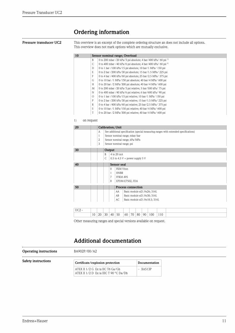
Ordering information
Pressure transducer UC2 This overview is an excerpt of the complete ordering structure an does not include all options.
This overview does not mark options which are mutually exclusive.
Other measuring ranges and special versions available on request.
Additional documentation
Operating instructions BA902P/00/A2
Safety instructions
10 Sensor nominal range; Overload
B 0 to 200 mbar /20 kPa/3 psi absolute; 4 bar/400 kPa/ 60 psi 1)
1) on request
C 0 to 400 mbar /40 kPa/6 psi absolute; 4 bar/400 kPa/ 60 psi )
D 0 to 1 bar /100 kPa/15 psi absolute; 10 bar/1 MPa/ 150 psi
E 0 to 2 bar /200 kPa/30 psi absolute; 15 bar/1.5 MPa/ 225 psi
F 0 to 4 bar /400 kPa/60 psi absolute; 25 bar/2.5 MPa/ 375 psi
G 0 to 10 bar /1 MPa/150 psi absolute; 40 bar/4 MPa/ 600 psi
H 0 to 20 bar /2 MPa/300 psi absolute; 40 bar/4 MPa/ 600 psi
M 0 to 200 mbar /20 kPa/3 psi relative; 5 bar/500 kPa/ 75 psi
N 0 to 400 mbar /40 kPa/6 psi relative; 6 bar/600 kPa/ 90 psi
O 0 to 1 bar /100 kPa/15 psi relative; 10 bar/1 MPa/ 150 psi
P 0 to 2 bar /200 kPa/30 psi relative; 15 bar/1.5 MPa/ 225 psi
R 0 to 4 bar /400 kPa/60 psi relative; 25 bar/2.5 MPa/ 375 psi
S 0 to 10 bar /1 MPa/150 psi relative; 40 bar/4 MPa/ 600 psi
T 0 to 20 bar /2 MPa/300 psi relative; 40 bar/4 MPa/ 600 psi
20 Calibration; Unit
A See additional specification (special measuring ranges with extended specifications)
1 Sensor nominal range; mbar/bar
2 Sensor nominal range; kPa/MPa
3 Sensor nominal range; psi
30 Output
B 4 to 20 mA
C 0.5 to 4.5 V + power supply 5 V
40 Sensor seal
0 FKM Viton
1 HNBR
7 FFKM 495
8 EPDM-E7502, FDA
50 Process connection
AA Basic module ø21.9x26; 316L
AB Basic module ø21.9x30; 316L
AC Basic module ø21.9x18.5; 316L
UC2 -
10 20 30 40 50 60 70 80 90 100 110
Certificate/explosion protection Documentation
ATEX II 1/2 G Ex ia IIC T6 Ga/Gb
ATEX II 1/2 D Ex ia IIIC T 90 °C Da/Db
– XA513P
Pressure Transducer UC2
OEM Products
Endress+Hauser GmbH+Co.KGHauptstraße 179689 Maulburg, Germany
Tel.: +49 76 22 28 21 47Fax: +49 76 22 28 20 49
E-Mail: [email protected]
TI902P/00/EN/05.10
FM+SGML 6.0