Embed Size (px)
Citation preview
MKS Baratron Type 631C
High Temperature Pressure Transducer
Instruction Manual
2 Technology Drive Andover, MA, USA 01810
Main: 978.645.5500 USA: 800.227.8766 www.mksinst.com
1034130-001
Revision C, 04/13 Instruction Manual
WARRANTY Type 631C Equipment
MKS Instruments, Inc. (MKS) warrants that for two years from the date of shipment the equipment described above (the “equipment”) manufactured by MKS shall be free from defects in materials and workmanship and will correctly perform all date-related operations, including without limitation accepting data entry, sequencing, sorting, comparing, and reporting, regardless of the date the operation is performed or the date involved in the operation, provided that, if the equipment exchanges data or is otherwise used with equipment, software, or other products of others, such products of others themselves correctly perform all date-related operations and store and transmit dates and date-related data in a format compatible with MKS equipment. THIS WARRANTY IS MKS’ SOLE WARRANTY CONCERNING DATE-RELATED OPERATIONS.
For the period commencing with the date of shipment of this equipment and ending two years later, MKS will, at its option, either repair or replace any part which is defective in materials or workmanship or with respect to the date-related operations warranty without charge to the purchaser. The foregoing shall constitute the exclusive and sole remedy of the purchaser for any breach by MKS of this warranty.
The purchaser, before returning any equipment covered by this warranty, which is asserted to be defective by the purchaser, shall make specific written arrange-ments with respect to the responsibility for shipping the equipment and handling any other incidental charges with the MKS sales representative or distributor from which the equipment was purchased or, in the case of a direct purchase from MKS, with the MKS home office in Andover, Massachusetts, USA.
This warranty does not apply to any equipment which has not been installed and used in accordance with the specifications recommended by MKS for the proper and normal use of the equipment. MKS shall not be liable under any circumstances for indirect, special, consequential, or incidental damages in connection with, or arising out of, the sale, performance, or use of the equipment covered by this warranty.
MKS recommends that all MKS pressure and flow products be calibrated periodically (typically every 6 to 12 months) to ensure accurate readings. When a product is returned to MKS for this periodic re-calibration it is considered normal preventative maintenance not covered by any warranty.
THIS WARRANTY IS IN LIEU OF ALL OTHER RELEVANT WARRANTIES, EXPRESSED OR IMPLIED, INCLUDING THE IMPLIED WARRANTY OF MERCHANTABILITY AND THE IMPLIED WARRANTY OF FITNESS FOR A PARTICULAR PURPOSE, AND ANY WARRANTY AGAINST INFRINGEMENT OF ANY PATENT.
4/13 1034130-001
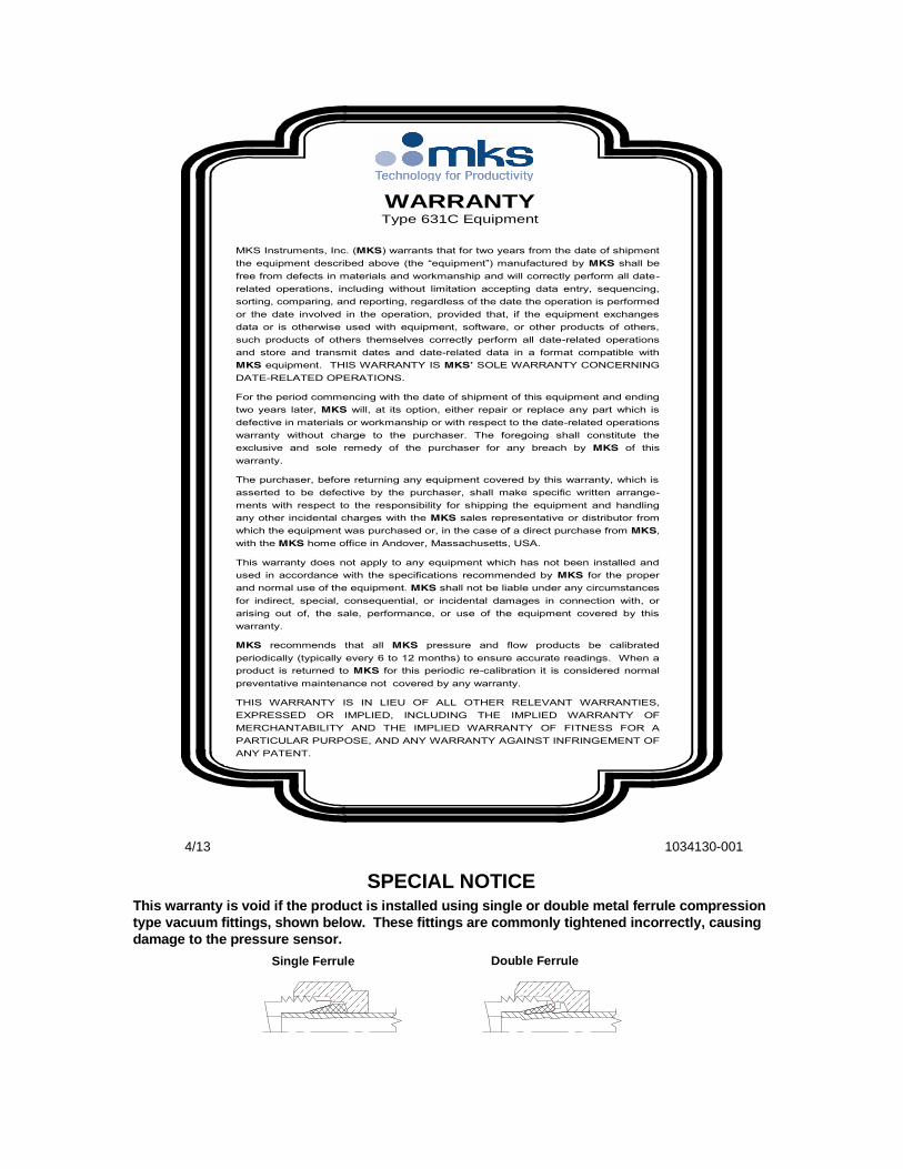
This warranty is void if the product is installed using single or double metal ferrule compression
type vacuum fittings, shown below. These fittings are commonly tightened incorrectly, causing
damage to the pressure sensor.
SPECIAL NOTICE
Single Ferrule Double Ferrule
1034310-001 Rev. C, 4/13
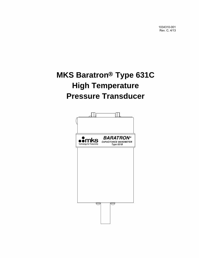
MKS Baratron Type 631C
High Temperature
Pressure Transducer
2
Copyright © 2013 by MKS Instruments, Inc.
All rights reserved. No part of this work may be reproduced or transmitted in any form or by any
means, electronic or mechanical, including photocopying and recording, or by any information
storage or retrieval system, except as may be expressly permitted in writing by MKS Instruments,
Inc.
Printed in the United States of America
Baratron is a registered trademark and Cluster Gauge is a trademark of MKS Instruments,
Inc., Andover, MA, USA.
Swagelok®, VCR®, VCO®, and Ultra-Torr® are registered trademarks of Swagelok Company,
Solon, OH, USA.
Tri-Clover® is a registered trademark of Tri-Clover, Inc., Kenosha, WI, USA.
Inconel® and Incoloy® are registered trademarks of Inco Alloys International, Inc., Huntington,
WV, USA.
Protected by U.S. Patent Numbers 4785669 and 5625152. Foreign patents pending.
Some Baratron® products may not be exported to many end user countries without both US and
local government export licenses under ECCN 2B230.
Table of Contents
iii
Table of Contents
Safety Information ....................................................................................................................... 1
Symbols Used in This Instruction Manual ...................................................................... 1
Symbols Found on the Unit ............................................................................................ 2
Safety Procedures and Precautions ................................................................................. 3
Sicherheitshinweise für den Druckmeßumformer ....................................................................... 5
In dieser Betriebsanleitung vorkommende Symbole ...................................................... 5
Erklärung der am Gerät angebrachten Symbole ............................................................. 6
Sicherheitsvorschriften und Vorsichtsmaßnahmen ......................................................... 7
Informations relatives à la sécurité pour le transducteur de pression .......................................... 9
Symboles utilisés dans ce manuel d'utilisation ............................................................... 9
Symboles apparaissant sur l'unité ................................................................................... 10
Mesures de sécurité et précautions ................................................................................. 11
Medidas de seguridad del transductor de presión ........................................................................ 13
Símbolos usados en este manual de instrucciones .......................................................... 13
Símbolos hallados en la unidad ....................................................................................... 14
Procedimientos y precauciones de seguridad ................................................................. 15
Chapter One: General Information ............................................................................................. 17
Introduction ..................................................................................................................... 17
How This Manual is Organized ...................................................................................... 18
Customer Support ........................................................................................................... 19
Chapter Two: Installation ........................................................................................................... 21
How To Unpack the Type 631C Unit ............................................................................. 21
Unpacking Checklist .......................................................................................... 21
Interface Cables .............................................................................................................. 22
Cable to Connect to the Power Supply .............................................................. 23
Product Location and Requirements ............................................................................... 23
Environmental Requirements ............................................................................ 24
Setup ............................................................................................................................... 25
General ............................................................................................................... 25
Environmental Considerations ........................................................................... 25

Table of Contents
iv
Sensor ................................................................................................................ 26
Piping Considerations and Port Connections .................................................................. 27
General ............................................................................................................... 27
Sensor Fittings ................................................................................................... 27
Chapter Three: Overview ............................................................................................................ 29
Sensor .............................................................................................................................. 29
Signal Conditioner .......................................................................................................... 29
Instrument Components and Dimensions ....................................................................... 29
Interface Connector ......................................................................................................... 33
Pressure Output ............................................................................................................... 34
Overpressure Considerations .......................................................................................... 34
Labels .............................................................................................................................. 34
Wiring Diagram Label ....................................................................................... 34
“Caution Hot” Label .......................................................................................... 35
Serial Number Label .......................................................................................... 35
Chapter Four: Operation ............................................................................................................. 37
How To Zero the Type 631 Transducer .......................................................................... 37
How To Adjust the Zero Potentiometer ............................................................. 38
How To Adjust the Coarse Zero Switch ............................................................ 39
Heater Status LEDs and Heater Alarm Relay ................................................................. 40
Over-Temperature Protection ............................................................................ 40
Chapter Five: Optional Relay System ......................................................................................... 43
General Information ........................................................................................................ 43
Trip Point Parameters ..................................................................................................... 43
Trip Point Values ............................................................................................... 43
Trip Point Direction ........................................................................................... 44
Chapter Six: Maintenance and Troubleshooting ......................................................................... 47
General Maintenance ...................................................................................................... 47
Troubleshooting .............................................................................................................. 48
High, Low, or Erratic Output, or No Output at All ............................................ 48
Appendix A: Product Specifications ........................................................................................... 49
Physical Specifications ................................................................................................... 49
Performance Specifications ............................................................................................ 50

Table of Contents
v
Environmental Specifications ......................................................................................... 50
Appendix B: Model Code Explanation ........................................................................................ 51
Model Code ..................................................................................................................... 51
Index ............................................................................................................................................ 55
Table of Contents
vi
List of Figures and Tables
Figures
Figure 1: Recommended Orientation of the Type 631C Transducer ........................................... 26
Figure 2: Top View of the Type 631C Transducer Without Optional Relay System .................. 30
Figure 3: Top View of the Type 631C Transducer With Optional Relay System ....................... 31
Figure 4: Dimensions of the Type 631C Transducer ................................................................... 32
Figure 5: Wiring Diagram Label .................................................................................................. 34
Figure 6: The “Caution Hot” Label .............................................................................................. 35
Figure 7: The Serial Number Label ............................................................................................. 35
Figure 8: Location of the Trip Point Adjustment Pots and Trip Point Signal Output ................. 44
Figure 9: LED and Relay State When Trip Point Direction Set Above Trip Point Value .......... 45
Figure 10: LED and Relay State When Trip Point Direction Set Below Trip Point Value ......... 45
Tables
Table 1: Definition of Symbols Found on the Unit......................................................................... 2
Tabelle 2: Bedeutung der am Gerät angebrachten Symbole ........................................................... 6
Tableau 3: Définition des symboles apparaissant sur l'unité ........................................................ 10
Tabla 4: Definición de los símbolos hallados en la unidad ............................................................ 14
Table 5: Interface Cables .............................................................................................................. 22
Table 6: Pinout of the Interface Connector (J1) ............................................................................. 34
Table 7: Highest Pressures Suggested for Proper Zero Adjustment .............................................. 38
Table 8: Over-Temperature Cutoff Value ...................................................................................... 41
Table 9: Conditions and resulting status LEDs and heater alarm relay output. ............................. 41
Safety Information
1
Safety Information
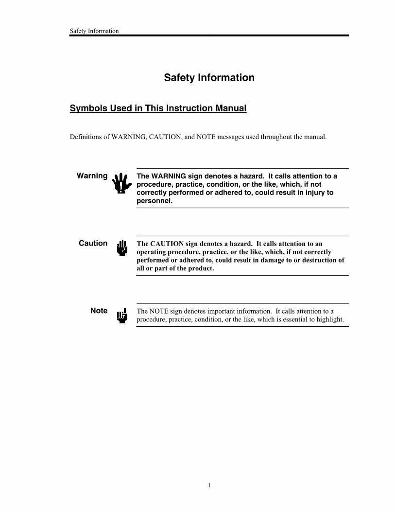
Symbols Used in This Instruction Manual
Definitions of WARNING, CAUTION, and NOTE messages used throughout the manual.
Warning
The WARNING sign denotes a hazard. It calls attention to a procedure, practice, condition, or the like, which, if not correctly performed or adhered to, could result in injury to personnel.
Caution
The CAUTION sign denotes a hazard. It calls attention to an
operating procedure, practice, or the like, which, if not correctly
performed or adhered to, could result in damage to or destruction of
all or part of the product.
Note
The NOTE sign denotes important information. It calls attention to a
procedure, practice, condition, or the like, which is essential to highlight.
Safety Information
2
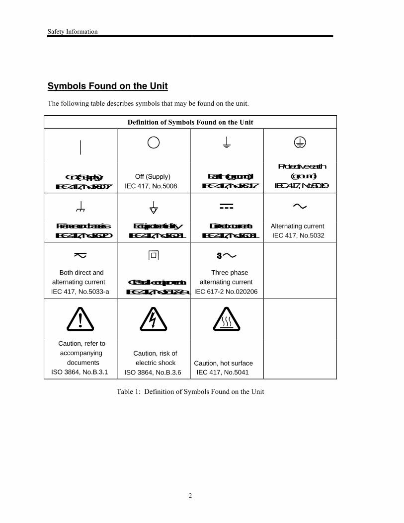
Symbols Found on the Unit
The following table describes symbols that may be found on the unit.
Definition of Symbols Found on the Unit
|
Off (Supply)IEC 417, No.5008
Alternating current
IEC 417, No.5032
Both direct and
alternating current
IEC 417, No.5033-a
Three phase
alternating current
IEC 617-2 No.020206
Caution, refer to
accompanying
documents
ISO 3864, No.B.3.1
Caution, risk of
electric shock
ISO 3864, No.B.3.6
Caution, hot surface
IEC 417, No.5041
Table 1: Definition of Symbols Found on the Unit
On (Supply)
IEC 417, No.5007
Earth (ground)
IEC 417, No.5017
Protective earth
(ground)
IEC 417, No.5019
Frame or chassis
IEC 417, No.5020
Equipotentiality
IEC 417, No.5021
Direct current
IEC 417, No.5031
Class ll equipment
IEC 417, No.5172-a
Safety Information
3
Safety Procedures and Precautions
The following general safety precautions must be observed during all phases of operation of this
instrument. Failure to comply with these precautions or with specific warnings elsewhere in this
manual violates safety standards of intended use of the instrument and may impair the
protection provided by the equipment. MKS Instruments, Inc. assumes no liability for the
customer’s failure to comply with these requirements.
DO NOT SUBSTITUTE PARTS OR MODIFY INSTRUMENT
Do not install substitute parts or perform any unauthorized modification to the instrument.
Return the instrument to an MKS Calibration and Service Center for service and repair to ensure
that all safety features are maintained.
SERVICE BY QUALIFIED PERSONNEL ONLY
Operating personnel must not remove instrument covers. Component replacement and internal
adjustments must be made by qualified service personnel only.
DO NOT OPERATE IN EXPLOSIVE ATMOSPHERES
To avoid explosion, do not operate this product in an explosive atmosphere unless it has been
specifically certified for such operation.
USE PROPER FITTINGS AND TIGHTENING PROCEDURES
All instrument fittings must be consistent with instrument specifications, and compatible with the
intended use of the instrument. Assemble and tighten fittings according to manufacturer's
directions.
CHECK FOR LEAK-TIGHT FITTINGS
Before proceeding to instrument setup, carefully check all plumbing connections to the
instrument to ensure leak-tight installation.
OPERATE AT SAFE INLET PRESSURES
This unit should never be operated at pressures higher than the rated maximum pressure (refer to
the product specifications for the maximum allowable pressure).
INSTALL A SUITABLE BURST DISC
When operating from a pressurized gas source, a suitable burst disc should be installed in the
vacuum system to prevent system explosion should the system pressure rise.
Safety Information
4
KEEP THE UNIT FREE OF CONTAMINANTS
Do not allow contaminants of any kind to enter the unit before or during use. Contamination such
as dust, dirt, lint, glass chips, and metal chips may permanently damage the unit.
USE CAUTION WHEN TOUCHING THE TRANSDUCER
The transducer (especially the bottom plate and tube) becomes hot when the system is in
operation.
Sicherheitshinweise für den Druckmeßumformer
5
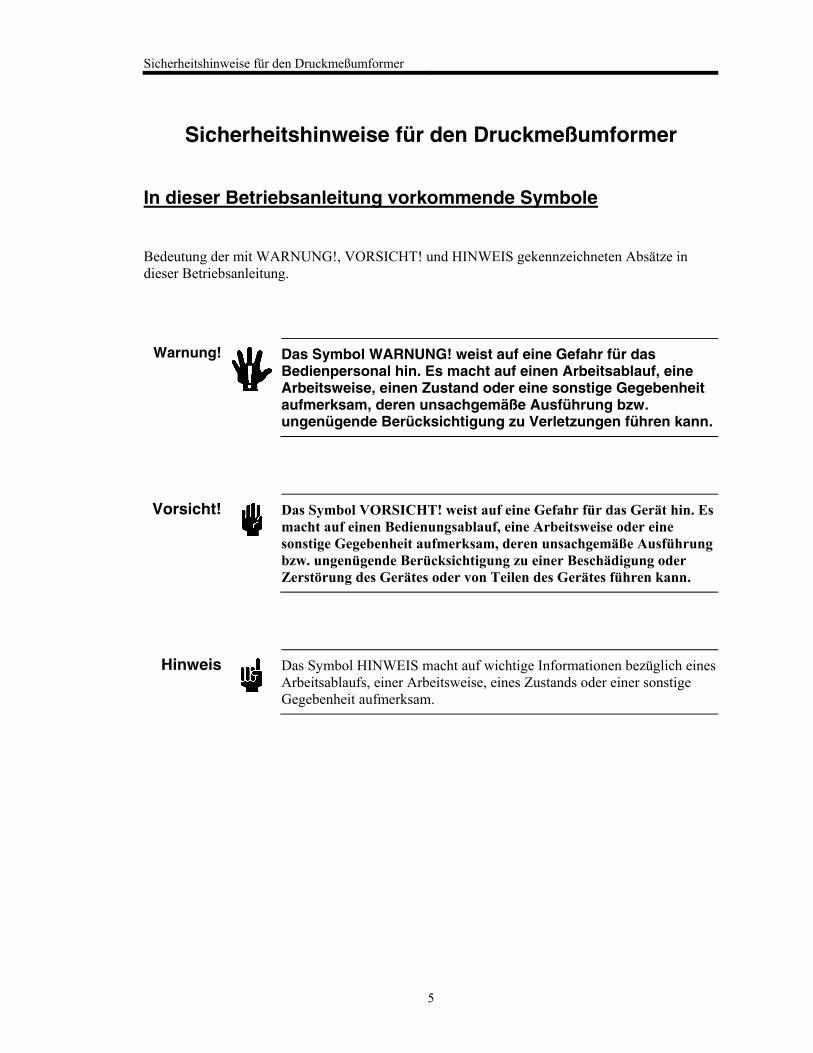
Sicherheitshinweise für den Druckmeßumformer
In dieser Betriebsanleitung vorkommende Symbole
Bedeutung der mit WARNUNG!, VORSICHT! und HINWEIS gekennzeichneten Absätze in
dieser Betriebsanleitung.
Warnung!
Das Symbol WARNUNG! weist auf eine Gefahr für das Bedienpersonal hin. Es macht auf einen Arbeitsablauf, eine Arbeitsweise, einen Zustand oder eine sonstige Gegebenheit aufmerksam, deren unsachgemäße Ausführung bzw. ungenügende Berücksichtigung zu Verletzungen führen kann.
Vorsicht!
Das Symbol VORSICHT! weist auf eine Gefahr für das Gerät hin. Es
macht auf einen Bedienungsablauf, eine Arbeitsweise oder eine
sonstige Gegebenheit aufmerksam, deren unsachgemäße Ausführung
bzw. ungenügende Berücksichtigung zu einer Beschädigung oder
Zerstörung des Gerätes oder von Teilen des Gerätes führen kann.
Hinweis
Das Symbol HINWEIS macht auf wichtige Informationen bezüglich eines
Arbeitsablaufs, einer Arbeitsweise, eines Zustands oder einer sonstige
Gegebenheit aufmerksam.
Sicherheitshinweise für den Druckmeßumformer
6
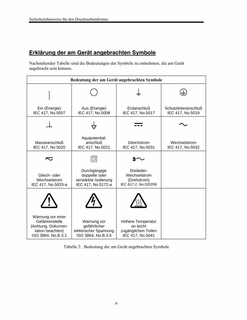
Erklärung der am Gerät angebrachten Symbole
Nachstehender Tabelle sind die Bedeutungen der Symbole zu entnehmen, die am Gerät
angebracht sein können.
Bedeutung der am Gerät angebrachten Symbole
|
Ein (Energie) IEC 417, No.5007
Aus (Energie) IEC 417, No.5008
Erdanschluß IEC 417, No.5017
Schutzleiteranschluß IEC 417, No.5019
Masseanschluß
IEC 417, No.5020
Aquipotential-anschluß
IEC 417, No.5021
Gleichstrom
IEC 417, No.5031
Wechselstrom
IEC 417, No.5032
Gleich- oder
Wechselstrom IEC 417, No.5033-a
Durchgängige doppelte oder
verstärkte Isolierung IEC 417, No.5172-a
Dreileiter-Wechselstrom (Drehstrom)
IEC 617-2, No.020206
Warnung vor einer Gefahrenstelle
(Achtung, Dokumen-tation beachten)
ISO 3864, No.B.3.1
Warnung vor gefährlicher
elektrischer Spannung ISO 3864, No.B.3.6
Höhere Temperatur
an leicht zugänglichen Teilen IEC 417, No.5041
Tabelle 2: Bedeutung der am Gerät angebrachten Symbole
Sicherheitshinweise für den Druckmeßumformer
7
Sicherheitsvorschriften und Vorsichtsmaßnahmen
Folgende allgemeine Sicherheitsvorschriften sind während allen Betriebsphasen dieses Gerätes
zu befolgen. Eine Mißachtung der Sicherheitsvorschriften und sonstiger Warnhinweise in dieser
Betriebsanleitung verletzt die für dieses Gerät und seine Bedienung geltenden
Sicherheitsstandards, und kann die Schutzvorrichtungen an diesem Gerät wirkungslos machen.
MKS Instruments, Inc. haftet nicht für Mißachtung dieser Sicherheitsvorschriften seitens des
Kunden.
Niemals Teile austauschen oder Änderungen am Gerät vornehmen!
Ersetzen Sie keine Teile mit baugleichen oder ähnlichen Teilen, und nehmen Sie keine
eigenmächtigen Änderungen am Gerät vor. Schicken Sie das Gerät zwecks Wartung und
Reparatur an den MKS-Kalibrierungs- und -Kundendienst ein. Nur so wird sichergestellt, daß alle
Schutzvorrichtungen voll funktionsfähig bleiben.
Wartung nur durch qualifizierte Fachleute!
Das Auswechseln von Komponenten und das Vornehmen von internen Einstellungen darf nur
von qualifizierten Fachleuten durchgeführt werden, niemals vom Bedienpersonal.
Vorsicht beim Arbeiten mit gefährlichen Stoffen!
Wenn gefährliche Stoffe verwendet werden, muß der Bediener die entsprechenden
Sicherheitsvorschriften genauestens einhalten, das Gerät, falls erforderlich, vollständig spülen,
sowie sicherstellen, daß der Gefahrstoff die am Gerät verwendeten Materialien, insbesondere
Dichtungen, nicht angreift.
Spülen des Gerätes mit Gas!
Nach dem Installieren oder vor dem Ausbau aus einem System muß das Gerät unter Einsatz eines
reinen Trockengases vollständig gespült werden, um alle Rückstände des Vorgängermediums zu
entfernen.
Anweisungen zum Spülen des Gerätes
Das Gerät darf nur unter einer Ablufthaube gespült werden. Schutzhandschuhe sind zu tragen.
Gerät nicht zusammen mit explosiven Stoffen, Gasen oder Dämpfen benutzen!
Um der Gefahr einer Explosion vorzubeugen, darf dieses Gerät niemals zusammen mit (oder in
der Nähe von) explosiven Stoffen aller Art eingesetzt werden, sofern es nicht ausdrücklich für
diesen Zweck zugelassen ist.
Sicherheitshinweise für den Druckmeßumformer
8
Anweisungen zum Installieren der Armaturen!
Alle Anschlußstücke und Armaturenteile müssen mit der Gerätespezifikation übereinstimmen,
und mit dem geplanten Einsatz des Gerätes kompatibel sein. Der Einbau, insbesondere das
Anziehen und Abdichten, muß gemäß den Anweisungen des Herstellers vorgenommen werden.
Verbindungen auf Undichtigkeiten prüfen!
Überprüfen Sie sorgfältig alle Verbindungen der Vakuumkomponenten auf undichte Stellen.
Gerät nur unter zulässigen Anschlußdrücken betreiben!
Betreiben Sie das Gerät niemals unter Drücken, die den maximal zulässigen Druck (siehe
Produktspezifikationen) übersteigen.
Geeignete Berstscheibe installieren!
Wenn mit einer unter Druck stehenden Gasquelle gearbeitet wird, sollte eine geeignete
Berstscheibe in das Vakuumsystem installiert werden, um eine Explosionsgefahr aufgrund von
steigendem Systemdruck zu vermeiden.
Verunreinigungen im Gerät vermeiden!
Stellen Sie sicher, daß Verunreinigungen jeglicher Art weder vor dem Einsatz noch während des
Betriebs in das Instrumenteninnere gelangen können. Staub- und Schmutzpartikel, Glassplitter
oder Metallspäne können das Gerät dauerhaft beschädigen oder Prozeß und Meßwerte
verfälschen.
Bei Geräten mit Temperaturkontrolle korrekte Anwärmzeit einhalten!
Temperaturkontrollierte Geräte arbeiten nur dann gemäß ihrer Spezifikation, wenn genügend Zeit
zum Erreichen und Stabilisieren der Betriebstemperatur eingeräumt wird. Kalibrierungen und
Nulleinstellungen sollten daher nur nach Abschluß des Anwärmvorgangs durchgeführt werden.
Informations relatives à la sécurité pour le transducteur de pression
9
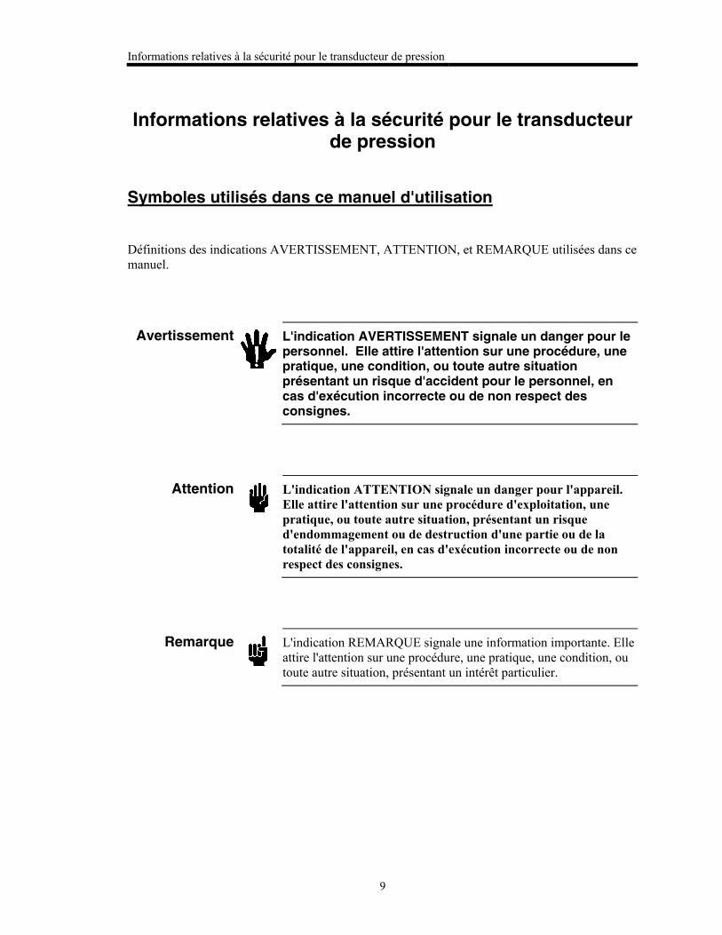
Informations relatives à la sécurité pour le transducteur de pression
Symboles utilisés dans ce manuel d'utilisation
Définitions des indications AVERTISSEMENT, ATTENTION, et REMARQUE utilisées dans ce
manuel.
Avertissement
L'indication AVERTISSEMENT signale un danger pour le personnel. Elle attire l'attention sur une procédure, une pratique, une condition, ou toute autre situation présentant un risque d'accident pour le personnel, en cas d'exécution incorrecte ou de non respect des consignes.
Attention
L'indication ATTENTION signale un danger pour l'appareil.
Elle attire l'attention sur une procédure d'exploitation, une
pratique, ou toute autre situation, présentant un risque
d'endommagement ou de destruction d'une partie ou de la
totalité de l'appareil, en cas d'exécution incorrecte ou de non
respect des consignes.
Remarque
L'indication REMARQUE signale une information importante. Elle
attire l'attention sur une procédure, une pratique, une condition, ou
toute autre situation, présentant un intérêt particulier.
Informations relatives à la sécurité pour le transducteur de pression
10
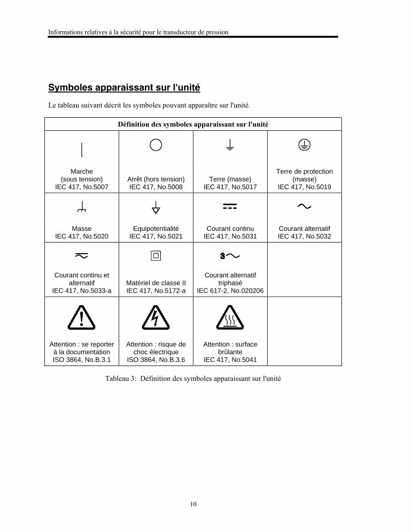
Symboles apparaissant sur l'unité
Le tableau suivant décrit les symboles pouvant apparaître sur l'unité.
Définition des symboles apparaissant sur l'unité
|
Marche (sous tension)
IEC 417, No.5007
Arrêt (hors tension) IEC 417, No.5008
Terre (masse)
IEC 417, No.5017
Terre de protection (masse)
IEC 417, No.5019
Masse IEC 417, No.5020
Equipotentialité IEC 417, No.5021
Courant continu IEC 417, No.5031
Courant alternatif IEC 417, No.5032
Courant continu et alternatif
IEC 417, No.5033-a
Matériel de classe II IEC 417, No.5172-a
Courant alternatif triphasé
IEC 617-2, No.020206
Attention : se reporter à la documentation ISO 3864, No.B.3.1
Attention : risque de choc électrique
ISO 3864, No.B.3.6
Attention : surface brûlante
IEC 417, No.5041
Tableau 3: Définition des symboles apparaissant sur l'unité
Informations relatives à la sécurité pour le transducteur de pression
11
Mesures de sécurité et précautions
Prendre les précautions générales de sécurité suivantes pendant toutes les phases d'exploitation
de cet appareil. Le non respect des ces précautions ou des avertissements contenus dans ce
manuel constitue une violation des normes de sécurité relatives à l'utilisation de l'appareil et
peut diminuer la protection fournie par l'appareil. MKS Instruments, Inc. n'assume aucune
responsabilité concernant le non respect des consignes par les clients.
PAS DE SUBSTITUTION DE PIÈCES OU DE MODIFICATION DE L'APPAREIL
Ne pas installer des pièces de substitution ou effectuer des modifications non autorisées sur
l'appareil. Renvoyer l'appareil à un centre de service et de calibrage MKS pour tout dépannage ou
réparation afin de garantir le l'intégrité des dispositifs de sécurité.
DÉPANNAGE UNIQUEMENT PAR DU PERSONNEL QUALIFIÉ
Le personnel d'exploitation ne doit pas essayer de remplacer des composants ou de faire des
réglages internes. Tout dépannage doit être uniquement effectué par du personnel qualifié.
PRÉCAUTION EN CAS D'UTILISATION AVEC DES PRODUITS DANGEREUX
Si des produits dangereux sont utilisés, l'utilisateur est responsable de la prise des mesures de
précaution appropriées, de la purge complète de l'appareil quand cela est nécessaire, et de la
garantie que les produits utilisés sont compatibles avec les composants de cet appareil, y compris
les matériaux d'étanchéité.
PURGE DE L'APPAREIL
Après l'installation de l'unité, ou avant son enlèvement d'un système, purger l'unité complètement
avec un gaz propre et sec afin d'éliminer toute trace du produit de flux utilisé précédemment.
UTILISATION DES PROCÉDURES APPROPRIÉES POUR LA PURGE
Cet appareil doit être purgé sous une hotte de ventilation, et il faut porter des gants de protection.
PAS D'EXPLOITATION DANS UN ENVIRONNEMENT EXPLOSIF
Pour éviter toute explosion, ne pas utiliser cet appareil dans un environnement explosif, sauf en
cas d'homologation spécifique pour une telle exploitation.
UTILISATION D'ÉQUIPEMENTS APPROPRIÉS ET PROCÉDURES DE SERRAGE
Tous les équipements de l'appareil doivent être cohérents avec ses spécifications, et compatibles
avec l'utilisation prévue de l'appareil. Assembler et serrer les équipements conformément aux
directives du fabricant.
Informations relatives à la sécurité pour le transducteur de pression
12
VÉRIFICATION DE L'ÉTANCHÉITÉ DES CONNEXIONS
Vérifier attentivement toutes les connexions des composants pour le vide afin de garantir
l'étanchéité de l'installation.
EXPLOITATION AVEC DES PRESSIONS D'ENTRÉE NON DANGEREUSES
Ne jamais utiliser des pressions supérieures à la pression nominale maximum (se reporter aux
spécifications de l'unité pour la pression maximum admissible).
INSTALLATION D'UN DISQUE D'ÉCHAPPEMENT ADAPTÉ
En cas d'exploitation avec une source de gaz pressurisé, installer un disque d'échappement adapté
dans le système à vide, afin d'éviter une explosion du système en cas d'augmentation de la
pression.
MAINTIEN DE L'UNITÉ À L'ABRI DES CONTAMINATIONS
Ne pas laisser des produits contaminants pénétrer dans l'unité avant ou pendant l'utilisation. Des
produits contaminants tels que des poussières et des fragments de tissu, de glace et de métal
peuvent endommager l'unité d'une manière permanente ou contaminer le processus.
RESPECT DU TEMPS D'ÉCHAUFFEMENT APPROPRIÉ POUR LES UNITÉS Á
TEMPÉRATURE CONTRÔLÉE
Les unités à température contrôlée atteignent leurs spécifications uniquement quand on leur laisse
un temps suffisant pour atteindre d'une manière stable la température d'exploitation. Ne pas
remettre à zéro ou calibrer l'unité tant que l'échauffement n'est pas terminé.
Medidas de seguridad del transductor de presión
13
Medidas de seguridad del transductor de presión
Símbolos usados en este manual de instrucciones
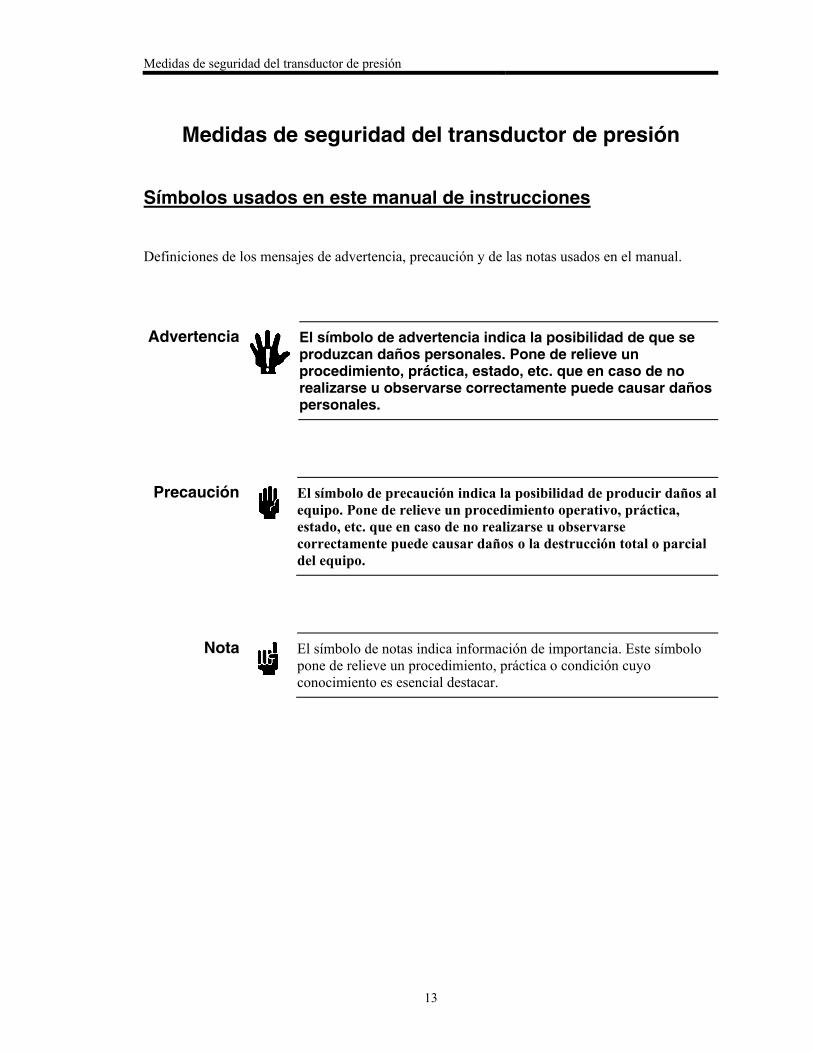
Definiciones de los mensajes de advertencia, precaución y de las notas usados en el manual.
Advertencia
El símbolo de advertencia indica la posibilidad de que se produzcan daños personales. Pone de relieve un procedimiento, práctica, estado, etc. que en caso de no realizarse u observarse correctamente puede causar daños personales.
Precaución
El símbolo de precaución indica la posibilidad de producir daños al
equipo. Pone de relieve un procedimiento operativo, práctica,
estado, etc. que en caso de no realizarse u observarse
correctamente puede causar daños o la destrucción total o parcial
del equipo.
Nota
El símbolo de notas indica información de importancia. Este símbolo
pone de relieve un procedimiento, práctica o condición cuyo
conocimiento es esencial destacar.
Medidas de seguridad del transductor de presión
14
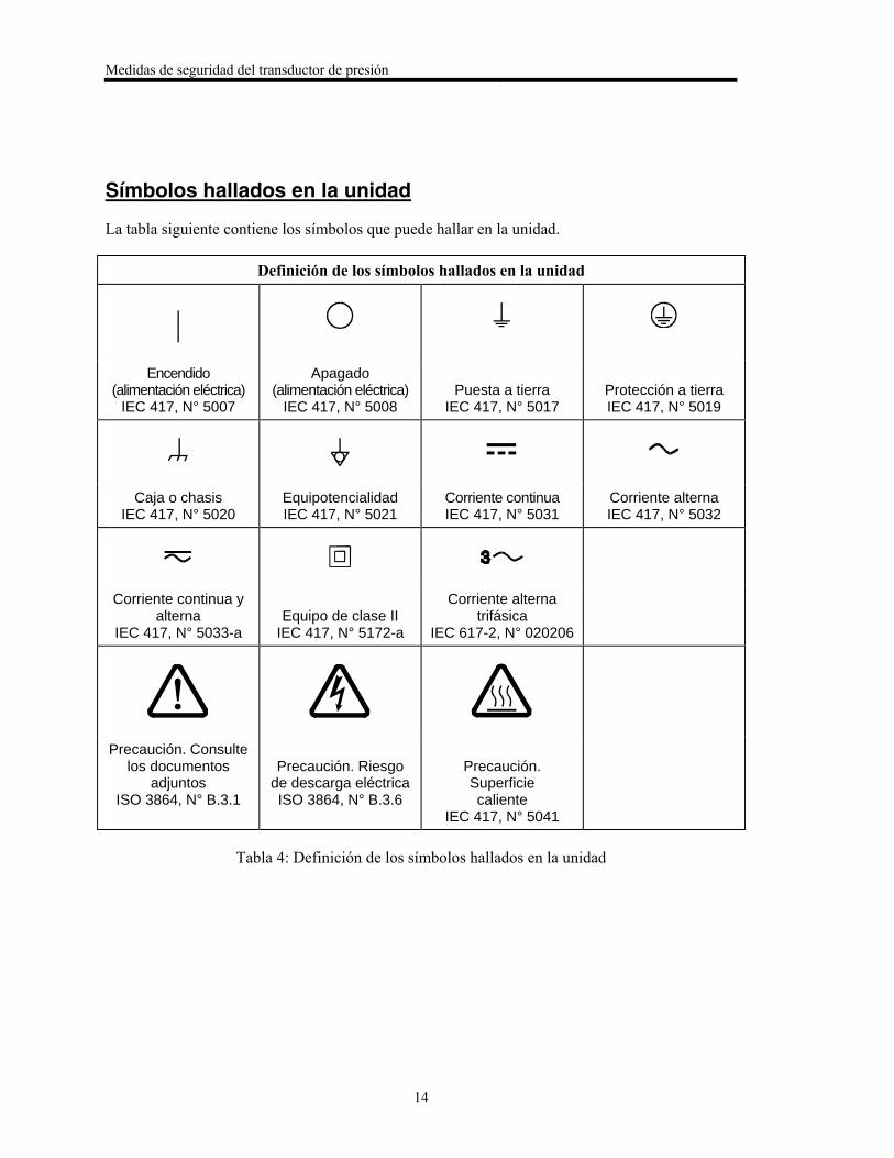
Símbolos hallados en la unidad
La tabla siguiente contiene los símbolos que puede hallar en la unidad.
Definición de los símbolos hallados en la unidad
|
Encendido (alimentación eléctrica)
IEC 417, N° 5007
Apagado (alimentación eléctrica)
IEC 417, N° 5008
Puesta a tierra
IEC 417, N° 5017
Protección a tierra IEC 417, N° 5019
Caja o chasis IEC 417, N° 5020
Equipotencialidad IEC 417, N° 5021
Corriente continua IEC 417, N° 5031
Corriente alterna IEC 417, N° 5032
Corriente continua y alterna
IEC 417, N° 5033-a
Equipo de clase II
IEC 417, N° 5172-a
Corriente alterna trifásica
IEC 617-2, N° 020206
Precaución. Consulte los documentos
adjuntos ISO 3864, N° B.3.1
Precaución. Riesgo
de descarga eléctrica ISO 3864, N° B.3.6
Precaución. Superficie caliente
IEC 417, N° 5041
Tabla 4: Definición de los símbolos hallados en la unidad
Medidas de seguridad del transductor de presión
15
Procedimientos y precauciones de seguridad
Las precauciones generales de seguridad descritas a continuación deben observarse durante
todas las etapas de funcionamiento del instrumento. La falta de cumplimiento de dichas
precauciones o de las advertencias específicas a las que se hace referencia en el manual,
constituye una violación de las normas de seguridad establecidas para el uso previsto del
instrumento y podría anular la protección proporcionada por el equipo. Si el cliente no cumple
dichas precauciones y advertencias, MKS Instruments, Inc. no asume responsabilidad legal
alguna.
NO UTILICE PIEZAS NO ORIGINALES O MODIFIQUE EL INSTRUMENTO
No instale piezas que no sean originales ni modifique el instrumento sin autorización. Para
asegurar el correcto funcionamiento de todos los dispositivos de seguridad, envíe el instrumento
al Centro de servicio y calibración de MKS toda vez que sea necesario repararlo o efectuar tareas
de mantenimiento.
LAS REPARACIONES DEBEN SER EFECTUADAS ÚNICAMENTE POR TÉCNICOS
AUTORIZADOS
Los operarios no deben intentar reemplazar los componentes o realizar tareas de ajuste en el
interior del instrumento. Las tareas de mantenimiento o reparación deben ser realizadas
únicamente por personal autorizado.
TENGA CUIDADO CUANDO TRABAJE CON MATERIALES TÓXICOS
Cuando se utilicen materiales tóxicos, es responsabilidad de los operarios tomar las medidas de
seguridad correspondientes, purgar totalmente el instrumento cuando sea necesario y comprobar
que el material utilizado sea compatible con los materiales del instrumento e inclusive, con todos
los materiales de sellado.
PURGUE EL INSTRUMENTO
Una vez instalada la unidad o antes de retirarla del sistema, purgue completamente la unidad con
gas limpio y seco para eliminar todo resto de la sustancia líquida empleada anteriormente.
USE PROCEDIMIENTOS ADECUADOS PARA REALIZAR LA PURGA
El instrumento debe purgarse debajo de una campana de ventilación y deben utilizarse guantes
protectores.
NO HAGA FUNCIONAR EL INSTRUMENTO EN AMBIENTES CON RIESGO DE
EXPLOSIÓN
Para evitar que se produzcan explosiones, no haga funcionar este instrumento en un ambiente con
riesgo de explosiones, excepto cuando el mismo haya sido certificado específicamente para tal
uso.
Medidas de seguridad del transductor de presión
16
USE ACCESORIOS ADECUADOS Y REALICE CORRECTAMENTE LOS
PROCEDIMIENTOS DE AJUSTE
Todos los accesorios del instrumento deben cumplir las especificaciones del mismo y ser
compatibles con el uso que se debe dar al instrumento. Arme y ajuste los accesorios de acuerdo
con las instrucciones del fabricante.
COMPRUEBE QUE LAS CONEXIONES SEAN A PRUEBA DE FUGAS
Inspeccione cuidadosamente las conexiones de los componentes de vacío para comprobar que
hayan sido instalados a prueba de fugas.
HAGA FUNCIONAR EL INSTRUMENTO CON PRESIONES DE ENTRADA SEGURAS
No haga funcionar nunca el instrumento con presiones superiores a la máxima presión nominal
(en las especificaciones del instrumento hallará la presión máxima permitida).
INSTALE UNA CÁPSULA DE SEGURIDAD ADECUADA
Cuando el instrumento funcione con una fuente de gas presurizado, instale una cápsula de
seguridad adecuada en el sistema de vacío para evitar que se produzcan explosiones cuando suba
la presión del sistema.
MANTENGA LA UNIDAD LIBRE DE CONTAMINANTES
No permita el ingreso de contaminantes en la unidad antes o durante su uso. Los productos
contaminantes tales como polvo, suciedad, pelusa, lascas de vidrio o virutas de metal pueden
dañar irreparablemente la unidad o contaminar el proceso.
CALIENTE ADECUADAMENTE LAS UNIDADES CONTROLADAS POR MEDIO DE
TEMPERATURA
Las unidades controladas por medio de temperatura funcionarán de acuerdo con las
especificaciones sólo cuando se las caliente durante el tiempo suficiente para permitir que lleguen
y se estabilicen a la temperatura de operación indicada. No calibre la unidad y no la ponga en
cero hasta que finalice el procedimiento de calentamiento.
Chapter One: General Information
17
Chapter One: General Information
Introduction
Note
Some Baratron® products may not be exported to many end user countries
without both US and local government export licenses under ECCN
2B230.
The MKS Baratron® Type 631C Absolute Pressure Transducer1 is part of the MKS family of
RoHS (Restriction of Hazardous Substances)-compliant, general purpose pressure transducers
designed to provide accurate, reliable and repeatable pressure measurements from 1000 Torr
down to 1 Torr, Full Scale (F.S.). The 631C is temperature controlled to prevent contamination
build-up and this transducer is available in one of two operating temperatures: 150 C and 200
C. These instruments have a small footprint and self-contained signal conditioning electronics
mounted directly above the sensor. The precision pressure transducer operates on a variable
capacitance technique2 and requires 15 VDC input to provide a 0 to 10 VDC output linear with
pressure over the F.S. sensor range.
The 631C transducer is available with an optional trip point relay system. The relay system
provides two internally mounted trip point relays with user adjustable pressure conditions that
will energize or de-energize each relay. The trip point relay system includes a status LED, trip
point value adjustment, direction selection and signal access for each of the two trip points.
The 631C pressure transducer is comprised of a sensor and signal conditioner. An MKS or
compatible power supply is required to complete the pressure-to-electronic output conversion. A
power supply/readout can also be used to provide a direct pressure display; the necessary Y-type
cables are available from MKS.
The 631C transducer measures absolute pressure, so only the measurement port has a connector.
During production, the reference port (PR) is pumped down to a pressure less than 10-7 Torr, and
outgassed thoroughly. A chemical getter is added to maintain the low pressure, and the port is
permanently sealed.
Temperature control of the transducer minimizes the effects of ambient or process temperature
variations typically encountered in process line environments. The sensor temperature is
continually monitored; two status LEDs provide visual indication of the unit’s temperature
control status. The LED labeled “Htr Fail Status” is normally off. If the sensor heater fails, the
LED becomes red and the associated relay becomes de-energized. The LED labeled “At Temp
Status” is yellow while the unit heats up and green when the unit is at the correct temperature.
(The unit requires a warm up time of two hours before any pressure data should be taken.)
Using the latest single sided, dual-electrode Inconel® sensor design, coupled with low impedance,
fixed-frequency bridge signal conditioner, these instruments are capable of withstanding high
overpressure conditions (45 psia). The high overpressure limit, coupled with the high temperature
operation, ensures maximum zero stability. The 631C transducer diaphragm design results in
1 U.S. Patent No. 5625152.
2 U.S. Patent No. 4785669.
Chapter One: General Information
18
extremely low hysteresis and the ability to specify a 0.50% accuracy as a percentage of Reading
instead of as a percentage of Full Scale. Since the accuracy is based on a percentage of Reading,
the transducer can be used over a wide dynamic measuring range without the need for re-ranging,
thus it provides accurate process monitoring over a variety of operating conditions.
This product can be used for pressure and vacuum measurements with a wide variety of process
gases, including (but not limited to) toxic, pyrophoric, and oxidizing materials such as silane
(SiH4), dichlorosilane (Cl2H2Si), trichlorosilane (Cl3HSi), anhydrous ammonia (NH3), ozone (O3),
and de-ionized water vapor (DIW). However, it is not recommended for use with corrosive or
explosive gases, so please contact the MKS Applications group or your local MKS Account
Manager if you plan to use the product with such gases.
This product contains electronic components made with non-toxic metals, and the packaging
materials are recyclable plastics. However, at the end of life of the product, decommissioning
must be performed in accordance with your local environmental regulations in consideration of
the chemicals and gases that this product has been exposed to.
How This Manual is Organized
This manual is designed to provide instructions on how to set up, install, and operate a Type
631C unit.
Before installing your Type 631C unit in a system and/or operating it, carefully read and
familiarize yourself with all precautionary notes in the Safety Messages and Procedures
section at the front of this manual. In addition, observe and obey all WARNING and
CAUTION notes provided throughout the manual.
Chapter One, General Information, (this chapter) introduces the product and describes the
organization of the manual.
Chapter Two, Installation, explains the environmental requirements and describes how to mount
the instrument in your system.
Chapter Three, Overview, gives a brief description of the instrument and its functionality.
Chapter Four, Operation, describes how to use the 631C unit and explains all the functions and
features.
Chapter Five, Optional Trip Point Relay System, discusses the optional relay system and its
parameters, including measuring and adjusting the trip point values and specifying the trip point
direction.
Chapter Six, Maintenance and Troubleshooting, provides a few maintenance recommendations
and a brief troubleshooting section. The Type 631C transducer is highly reliable and requires
little maintenance.
Appendix A, Product Specifications, lists the specifications of the instrument.
Appendix B, Model Code Explanation, describes the model code.
Chapter One: General Information
19
Customer Support
Standard maintenance and repair services are available at all of our regional MKS Calibration and
Service Centers, listed on the back cover. In addition, MKS accepts the instruments of other
manufacturers for recalibration using the Primary and Transfer Standard calibration equipment
located at all of our regional service centers. Should any difficulties arise in the use of your Type
631C instrument, or to obtain information about companion products MKS offers, contact any
authorized MKS Calibration and Service Center. If it is necessary to return the instrument to
MKS, please obtain an RMA Number (Return Material Authorization Number) from the MKS
Calibration and Service Center before shipping. The RMA Number expedites handling and
ensures proper servicing of your instrument.
Please refer to the inside of the back cover of this manual for a list of MKS Calibration and
Service Centers.
Warning
All returns to MKS Instruments must be free of harmful, corrosive, radioactive, or toxic materials.

Chapter One: General Information
20
This page intentionally left blank.
Chapter Two: Installation
21
Chapter Two: Installation
How To Unpack the Type 631C Unit
MKS has carefully packed the Type 631C unit so that it will reach you in perfect operating order.
Upon receiving the unit, however, you should check for defects, cracks, broken connectors, etc.,
to be certain that damage has not occurred during shipment.
Note
Do not discard any packing materials until you have completed your
inspection and are sure the unit arrived safely.
If you find any damage, notify your carrier and MKS immediately. If it is necessary to return the
unit to MKS, obtain an RMA Number (Return Material Authorization Number) from the MKS
Service Center before shipping. Please refer to the inside of the back cover of this manual for a
list of MKS Calibration and Service Centers.
Caution
Only qualified individuals should perform the installation and any
user adjustments. They must comply with all the necessary ESD and
handling precautions while installing and adjusting the instrument.
Proper handling is essential when working with all highly sensitive
precision electronic instruments.
Unpacking Checklist
Standard Equipment:
Type 631C Unit
Type 631C Instruction Manual (this book)
Chapter Two: Installation
22
Optional Equipment:
Interface cables, refer to Interface Cables, page 22, for details
Electrical Connector Accessories Kit: 631C-K1 (contains a mating connector)
MKS Type PR4000B Electronic Display Unit
All MKS automatic pressure controllers (Type 651, 1651, and others)
Note
The Type 651 pressure controller must include the high power supply
option (2.0 Amperes) to work with a 631C transducer. A Type PR4000B
must also be equipped with the 1.5 Ampere output to be used with this
Baratron.
Interface Cables
As of July 20, 2009, all products shipped to the European Community must comply with the EMC
Directive 2004/108/EC, which covers radio frequency emissions and immunity tests. MKS
products that meet these requirements are identified by application of the CE Mark.
MKS offers the following interface cables to connect the 631C unit to your system.
Interface Cables
Cable Number Number of Power Supplies
CB631-1- xx 1
CB631S-1- xx 1
xx designates the length of the cable, in feet
Table 5: Interface Cables
Chapter Two: Installation
23
Cable to Connect to the Power Supply
The 631C transducer is powered by a single 15 VDC power supply for both the electronics and
heater. The cable connection to the 631C transducer via the Interface connector is shown in
Figure 2: Top View of the Type 631C Transducer, page 30. Refer to Table 6: Pinout of the
Interface Connector (J1), page 34, for the complete list of pin assignments for the Interface
connector.
Product Location and Requirements
Voltage: 15 VDC (±5%)
Current: 1.0 Amp, maximum for the heater and electronics
Overpressure limits: 45 psia or 120% of sensor Full Scale, whichever is greater
Mount the Type 631C transducer components correctly: refer to Figure 1: Recommended
Orientation of the Type 631C Transducer, page 26, for the recommended orientation of the
sensor
Maintain a solid system ground for proper operation and safety to personnel
Isolate the unit from vibration
Keep the unit free from vibration. The diaphragm may be susceptible to resonance when
there is not enough gas present to dampen the effects of vibration. The 1 and 2 Torr Full
Scale units are the most sensitive. Any vibration that does exist should be isolated from the
unit with vibration isolation mounting and a bellows coupling.
Warm up Time: 2 hours
Chapter Two: Installation
24
Environmental Requirements
Caution
DO NOT use a thermal blanket on the 631C unit. The 631C
transducer is designed to maintain its specified operating
temperature without external assistance.
Operating ambient temperature:
150 C units: 10° to 50° C (50° to 122° F)
200 C units: 10° to 50° C (50° to 122° F)
Caution
Airflow of at least 50 ft/min is REQUIRED for 150 C units if the
ambient temperature is 45 to 50 C (113 to 122F).
Airflow of at least 150 ft/min is REQUIRED for 200 C units if the
ambient temperature is 40 to 50 C (104 to 122F).
Ventilation requirements include sufficient air circulation
Caution
All high temperature equipment, including the 631C transducer
requires sufficient air circulation to prevent heat buildup. If the 631C
transducer is placed in an environment with still air or insufficient air
circulation, the temperature of the air surrounding the transducer
will rise. You must provide sufficient air circulation to prevent heat
build up around the 631C transducer.
Storage Humidity Range: 25% to 95% relative humidity, non-condensing
Storage Temperature Range: -20 to +80 C (-4 to 176 F)
Chapter Two: Installation
25
Setup
General
To obtain maximum accuracy from your Type 631C transducer, be sure the interconnecting
piping and the transducer components themselves are properly installed. Some general guidelines
are:
Mount the transducer such that vibration, shock, and temperature fluctuations are
minimized, and that the product’s inlet always points downward or horizontally.
Minimize interconnecting piping
Ensure adequate room to maintain environmental requirements and safety considerations,
and to provide easy access for calibration
Environmental Considerations
The 631C high temperature transducer is designed to operate at its specified operating
temperature. To meet this high operating temperature, you must follow these guidelines:
DO NOT use a thermal blanket on the 631C transducer
The addition of a thermal blanket will cause the electronics to overheat.
Provide adequate air circulation
Sufficient air circulation is necessary to prevent heat buildup within the transducer.
Warning
Airflow of at least 50 ft/min is REQUIRED for 150 C units if the
ambient temperature is 45 to 50 C (113 to 122F).
Airflow of at least 150 ft/min is REQUIRED for 200 C units if the
ambient temperature is 40 to 50 C (104 to 122F).
Chapter Two: Installation
26
Sensor
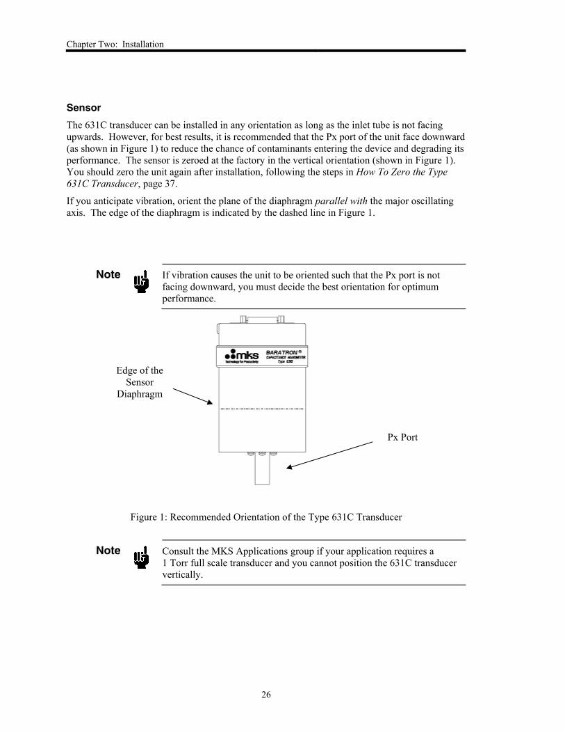
The 631C transducer can be installed in any orientation as long as the inlet tube is not facing
upwards. However, for best results, it is recommended that the Px port of the unit face downward
(as shown in Figure 1) to reduce the chance of contaminants entering the device and degrading its
performance. The sensor is zeroed at the factory in the vertical orientation (shown in Figure 1).
You should zero the unit again after installation, following the steps in How To Zero the Type
631C Transducer, page 37.
If you anticipate vibration, orient the plane of the diaphragm parallel with the major oscillating
axis. The edge of the diaphragm is indicated by the dashed line in Figure 1.
Note
If vibration causes the unit to be oriented such that the Px port is not
facing downward, you must decide the best orientation for optimum
performance.
Figure 1: Recommended Orientation of the Type 631C Transducer
Note
Consult the MKS Applications group if your application requires a
1 Torr full scale transducer and you cannot position the 631C transducer
vertically.
Edge of the
Sensor
Diaphragm
Px Port
Chapter Two: Installation
27
Piping Considerations and Port Connections
General
Position a line tap above or to the side of the process line, and position the sensor above
the line tap
This allows any liquids which may be present to drain into the process line.
Install the interconnecting piping so that it slopes away from the sensor to the process line
A slope of 1 inch per foot (8 centimeters per meter) is adequate.
Purge the interconnecting piping (close to the process tap) when needed to prevent
sediment buildup
When purging, be sure to isolate the sensor from the interconnecting piping.
Sensor Fittings
The following additional fittings are available for the Type 631C transducer:
½” (12.7 mm) tubing
Swagelok® 8-VCR® female
NW16-KF
1½” Tri-Clover®
2” Tri-Clover
Special Note for ½” (12.7 mm) Tubing
The standard tubing for the 631C transducer is straight ½” (12.7 mm) tubing. The Type 631C
transducer has only one pressure port (Px).
To connect the 631C transducer to a Swagelok® Ultra-Torr® compression fitting:
1. Ensure the tubing is clean and free of axial scratches.
2. Insert the tubing through the compression nut and O-ring all the way to the shoulder.
3. Tighten the nut.

Chapter Two: Installation
28
This page intentionally left blank.
Chapter Three: Overview
29
Chapter Three: Overview
Sensor
The Type 631C transducer contains an absolute sensor that is referenced to high vacuum (less
than 10-7 Torr). This pressure sensor utilizes a single-sided, dual-electrode/AC bridge circuit
design. In this design, two capacitance electrodes are deposited upon a ceramic disk in a
concentric “bull’s-eye” arrangement. The disk is positioned close to an Inconel® tensioned
diaphragm to form two capacitors in an AC bridge circuit. The other side of the diaphragm is
exposed to the process gas.
The diaphragm deflects with changing pressure—force per unit area—independent of the
composition of the measured gas. This deflection causes a capacitance change between the
diaphragm and the adjacent electrode assembly. When pressure is equal on both sides of the
diaphragm, the bridge is balanced. As pressure deflects the diaphragm toward the electrode, the
center capacitance changes more than the outer capacitance, causing the bridge to become
unbalanced and an AC voltage to be generated.
Signal Conditioner
The signal conditioner contains the state-of-the-art, low impedance balanced bridge circuitry,
self-compensated for thermal stability with ambient temperature changes. The output is linear
with pressure and provides a 0 VDC output at Zero pressure and a 10 VDC output at sensor Full
Scale.
Instrument Components and Dimensions
The 631C transducer has two adjustments for zero, a potentiometer and a coarse zero switch. The
location of both are the same for the 631C with and without the trip point relay system and are
shown in Figure 2: Top View of the Type 631C Transducer Without Optional Relay System and
Figure 3: Top View of the Type 631C Transducer With Optional Relay System, pages 30 and 31,
respectively.
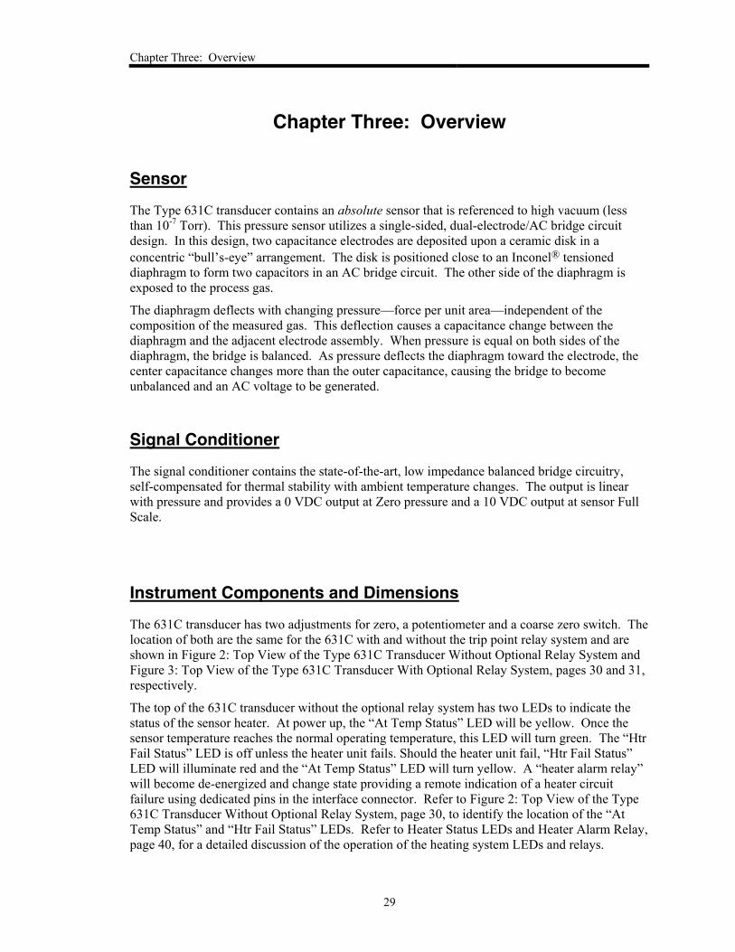
The top of the 631C transducer without the optional relay system has two LEDs to indicate the
status of the sensor heater. At power up, the “At Temp Status” LED will be yellow. Once the
sensor temperature reaches the normal operating temperature, this LED will turn green. The “Htr
Fail Status” LED is off unless the heater unit fails. Should the heater unit fail, “Htr Fail Status”
LED will illuminate red and the “At Temp Status” LED will turn yellow. A “heater alarm relay”
will become de-energized and change state providing a remote indication of a heater circuit
failure using dedicated pins in the interface connector. Refer to Figure 2: Top View of the Type
631C Transducer Without Optional Relay System, page 30, to identify the location of the “At
Temp Status” and “Htr Fail Status” LEDs. Refer to Heater Status LEDs and Heater Alarm Relay,
page 40, for a detailed discussion of the operation of the heating system LEDs and relays.
Chapter Three: Overview
30
Figure 2: Top View of the Type 631C Transducer Without Optional Relay System
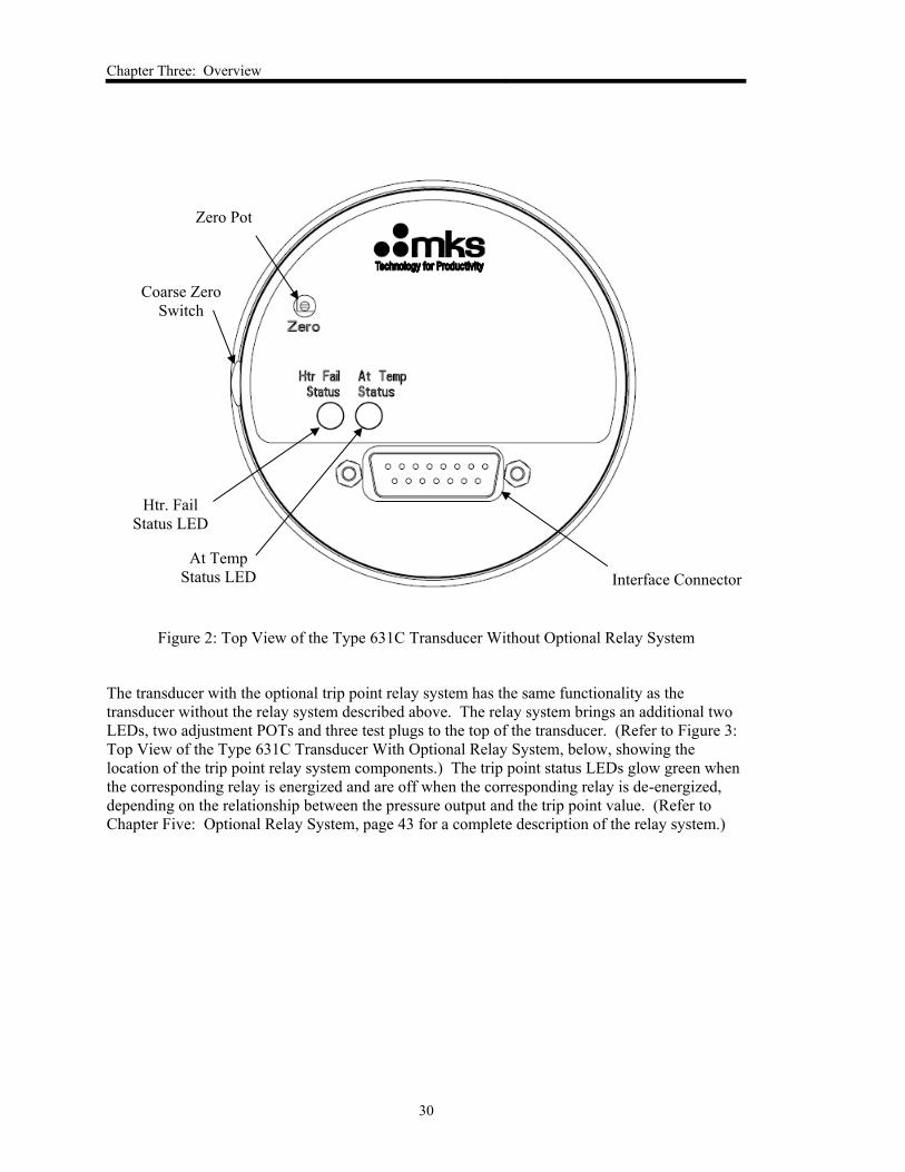
The transducer with the optional trip point relay system has the same functionality as the
transducer without the relay system described above. The relay system brings an additional two
LEDs, two adjustment POTs and three test plugs to the top of the transducer. (Refer to Figure 3:
Top View of the Type 631C Transducer With Optional Relay System, below, showing the
location of the trip point relay system components.) The trip point status LEDs glow green when
the corresponding relay is energized and are off when the corresponding relay is de-energized,
depending on the relationship between the pressure output and the trip point value. (Refer to
Chapter Five: Optional Relay System, page 43 for a complete description of the relay system.)
Zero Pot
Htr. Fail
Status LED
Interface Connector
At Temp
Status LED
Coarse Zero
Switch
Chapter Three: Overview
31
Figure 3: Top View of the Type 631C Transducer With Optional Relay System
Zero Pot
Htr. Fail
Status LED
Interface Connector At Temp
Status LED
Coarse
Zero
Switch
Relay system
described in
Chapter Five
Chapter Three: Overview
32
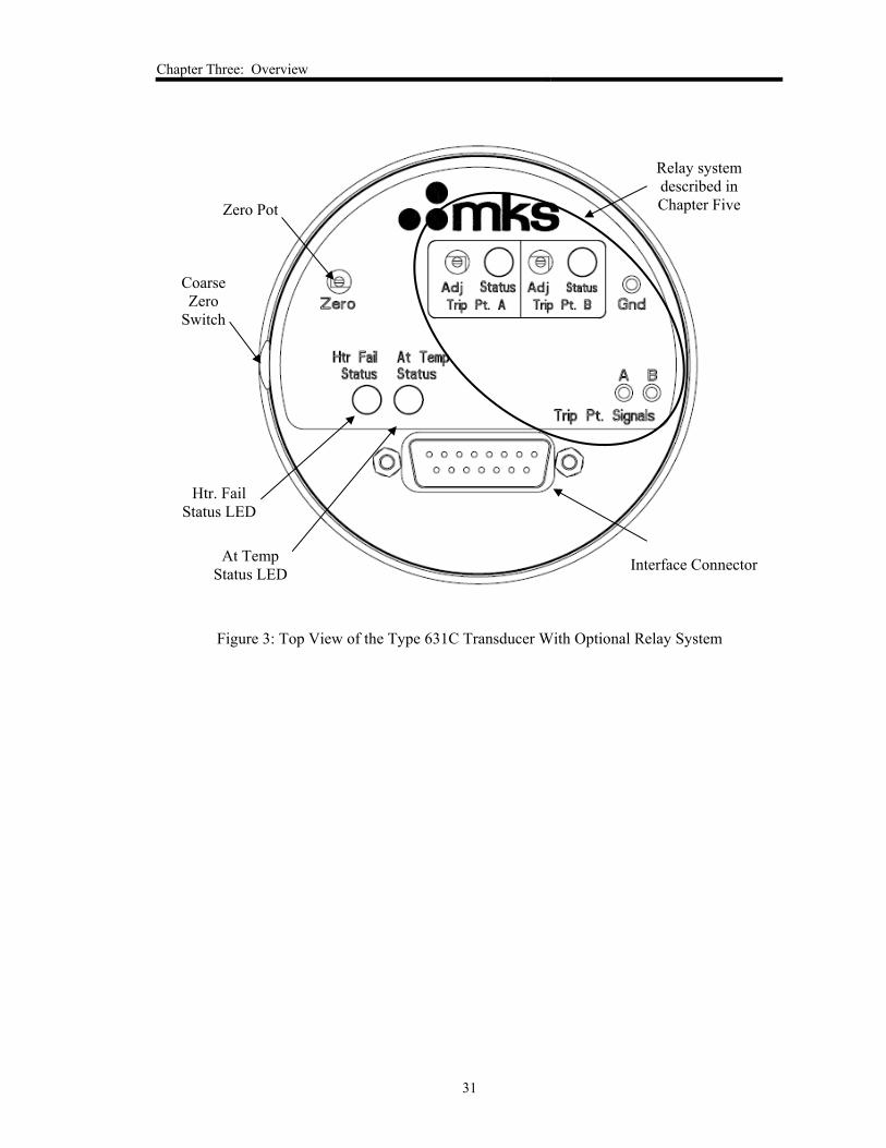
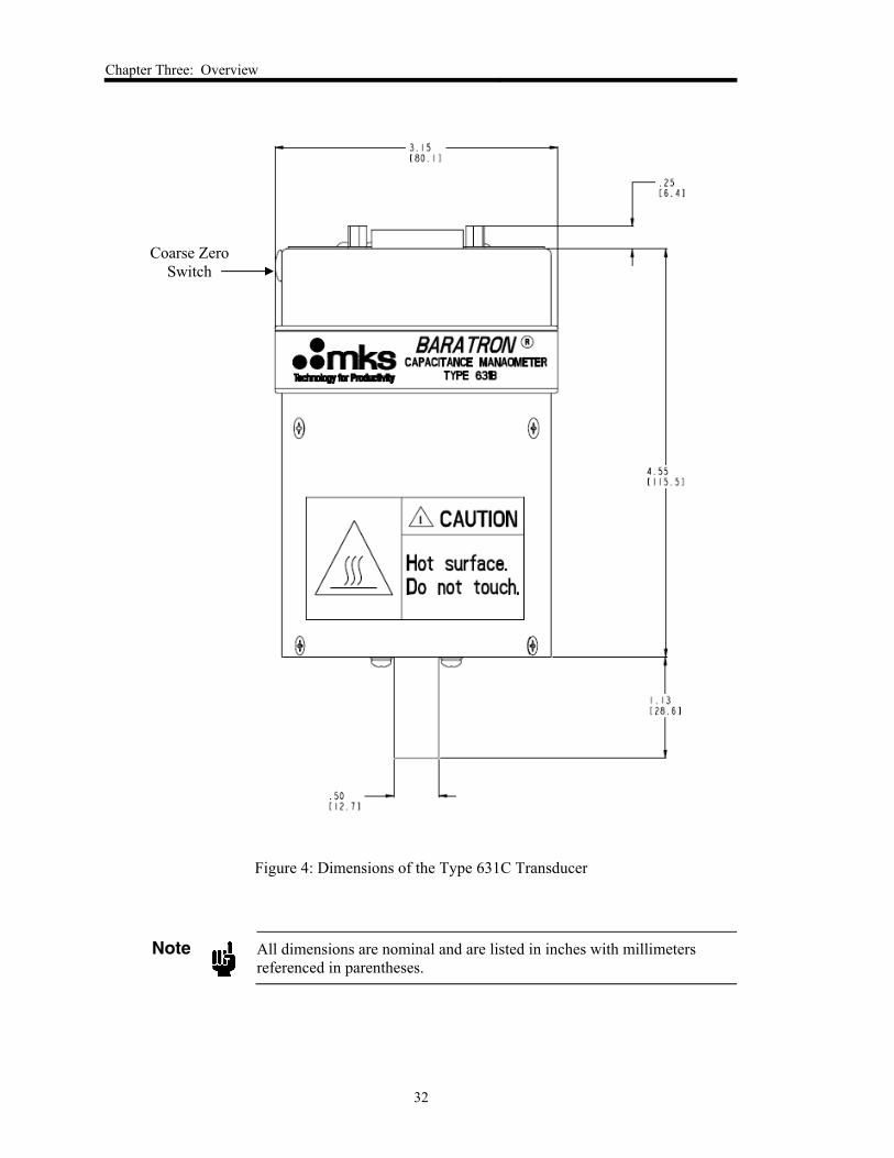
Figure 4: Dimensions of the Type 631C Transducer
Note
All dimensions are nominal and are listed in inches with millimeters
referenced in parentheses.
Coarse Zero
Switch
Chapter Three: Overview
33
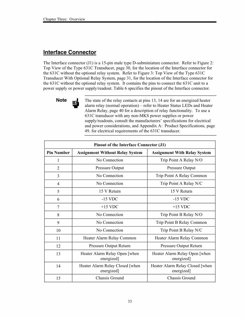
Interface Connector
The Interface connector (J1) is a 15-pin male type D-subminiature connector. Refer to Figure 2:
Top View of the Type 631C Transducer, page 30, for the location of the Interface connector for
the 631C without the optional relay system. Refer to Figure 3: Top View of the Type 631C
Transducer With Optional Relay System, page 31, for the location of the Interface connector for
the 631C without the optional relay system. It contains the pins to connect the 631C unit to a
power supply or power supply/readout. Table 6 specifies the pinout of the Interface connector.
Note
The state of the relay contacts at pins 13, 14 are for an energized heater
alarm relay (normal operation) – refer to Heater Status LEDs and Heater
Alarm Relay, page 40 for a description of relay functionality. To use a
631C transducer with any non-MKS power supplies or power
supply/readouts, consult the manufacturers’ specifications for electrical
and power considerations, and Appendix A: Product Specifications, page
49, for electrical requirements of the 631C transducer.
Pinout of the Interface Connector (J1)
Pin Number Assignment Without Relay System Assignment With Relay System
1 No Connection Trip Point A Relay N/O
2 Pressure Output Pressure Output
3 No Connection Trip Point A Relay Common
4 No Connection Trip Point A Relay N/C
5 15 V Return 15 V Return
6 -15 VDC -15 VDC
7 +15 VDC +15 VDC
8 No Connection Trip Point B Relay N/O
9 No Connection Trip Point B Relay Common
10 No Connection Trip Point B Relay N/C
11 Heater Alarm Relay Common Heater Alarm Relay Common
12 Pressure Output Return Pressure Output Return
13 Heater Alarm Relay Open [when
energized]
Heater Alarm Relay Open [when
energized]
14 Heater Alarm Relay Closed [when
energized]
Heater Alarm Relay Closed [when
energized]
15 Chassis Ground Chassis Ground
Chapter Three: Overview
34
Table 6: Pinout of the Interface Connector (J1)
Pressure Output
The 631C transducer provides a 0 to 10 VDC output signal at pressures of 100% of its full-scale
range and below.
Overpressure Considerations
As with any transducer, the 631C transducer performs valid measurements up to the unit’s Full
Scale. At pressures of roughly 10% over the Full Scale range, a high (≥ 11 VDC) output signal is
produced to warn of invalid readings. This high output signal varies from device to device, and is
not linear with further changes in pressure. At pressures somewhat beyond 110% of the Full
Scale range, the diaphragm touches the fixed capacitor plate. The capacitor plate serves as a
protective overpressure stop to prevent damage to the diaphragm up to 45 psia for an absolute
transducer.
Note
The output signal of the 631C above its full-scale measurement range is
not linear or repeatable, and should not be used for quantitative
measurements or process control. MKS does not guarantee that the
product will meet any of its published performance specifications above
110% of its full-scale range.
Labels
Three labels appear on the 631C unit: a wiring diagram label, a “Danger Hot” label, and a serial
number label.
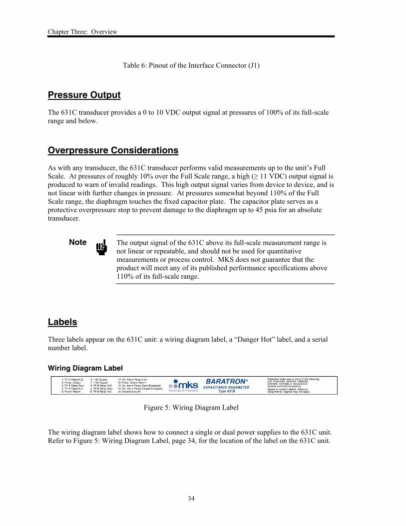
Wiring Diagram Label
Figure 5: Wiring Diagram Label
The wiring diagram label shows how to connect a single or dual power supplies to the 631C unit.
Refer to Figure 5: Wiring Diagram Label, page 34, for the location of the label on the 631C unit.
Chapter Three: Overview
35
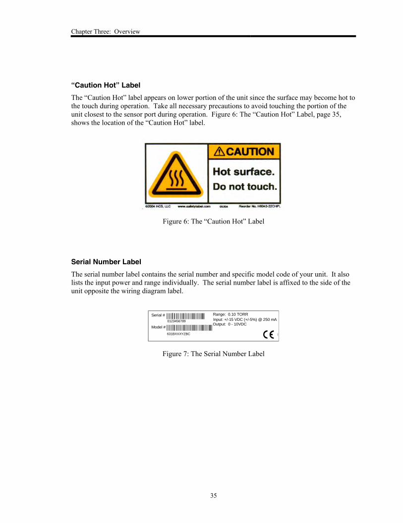
“Caution Hot” Label
The “Caution Hot” label appears on lower portion of the unit since the surface may become hot to
the touch during operation. Take all necessary precautions to avoid touching the portion of the
unit closest to the sensor port during operation. Figure 6: The “Caution Hot” Label, page 35,
shows the location of the “Caution Hot” label.
Figure 6: The “Caution Hot” Label
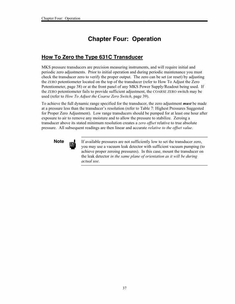
Serial Number Label
The serial number label contains the serial number and specific model code of your unit. It also
lists the input power and range individually. The serial number label is affixed to the side of the
unit opposite the wiring diagram label.
Serial #
Model #
Range: 0.10 TORR
Input: +/-15 VDC (+/-5%) @ 250 mAOutput: 0 - 10VDC
0123456789
631BXXXYZBC
Figure 7: The Serial Number Label

Chapter Three: Overview
36
This page intentionally left blank.
Chapter Four: Operation
37
Chapter Four: Operation
How To Zero the Type 631C Transducer
MKS pressure transducers are precision measuring instruments, and will require initial and
periodic zero adjustments. Prior to initial operation and during periodic maintenance you must
check the transducer zero to verify the proper output. The zero can be set (or reset) by adjusting
the ZERO potentiometer located on the top of the transducer (refer to How To Adjust the Zero
Potentiometer, page 38) or at the front panel of any MKS Power Supply/Readout being used. If
the ZERO potentiometer fails to provide sufficient adjustment, the COARSE ZERO switch may be
used (refer to How To Adjust the Coarse Zero Switch, page 39).
To achieve the full dynamic range specified for the transducer, the zero adjustment must be made
at a pressure less than the transducer’s resolution (refer to Table 7: Highest Pressures Suggested
for Proper Zero Adjustment). Low range transducers should be pumped for at least one hour after
exposure to air to remove any moisture and to allow the pressure to stabilize. Zeroing a
transducer above its stated minimum resolution creates a zero offset relative to true absolute
pressure. All subsequent readings are then linear and accurate relative to the offset value.
Note
If available pressures are not sufficiently low to set the transducer zero,
you may use a vacuum leak detector with sufficient vacuum pumping (to
achieve proper zeroing pressures). In this case, mount the transducer on
the leak detector in the same plane of orientation as it will be during
actual use.
Chapter Four: Operation
38
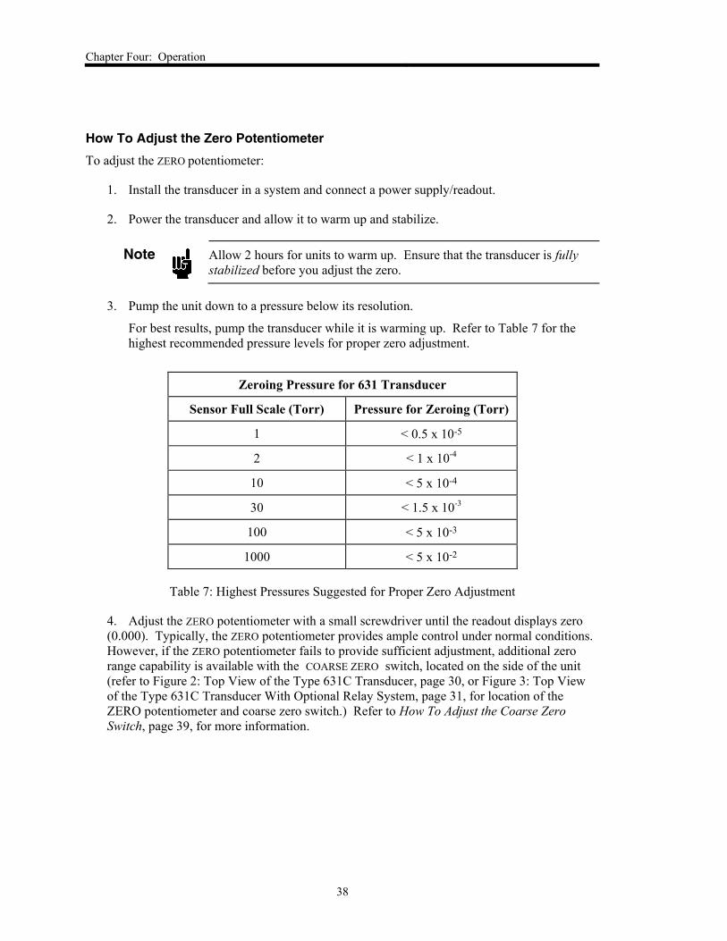
How To Adjust the Zero Potentiometer
To adjust the ZERO potentiometer:
1. Install the transducer in a system and connect a power supply/readout.
2. Power the transducer and allow it to warm up and stabilize.
Note
Allow 2 hours for units to warm up. Ensure that the transducer is fully
stabilized before you adjust the zero.
3. Pump the unit down to a pressure below its resolution.
For best results, pump the transducer while it is warming up. Refer to Table 7 for the
highest recommended pressure levels for proper zero adjustment.
Zeroing Pressure for 631 Transducer
Sensor Full Scale (Torr) Pressure for Zeroing (Torr)
1 < 0.5 x 10⁻⁵
2 < 1 x 10⁻⁴
10 < 5 x 10⁻⁴
30 < 1.5 x 10⁻³
100 < 5 x 10⁻³
1000 < 5 x 10⁻²
Table 7: Highest Pressures Suggested for Proper Zero Adjustment
4. Adjust the ZERO potentiometer with a small screwdriver until the readout displays zero
(0.000). Typically, the ZERO potentiometer provides ample control under normal conditions.
However, if the ZERO potentiometer fails to provide sufficient adjustment, additional zero
range capability is available with the COARSE ZERO switch, located on the side of the unit
(refer to Figure 2: Top View of the Type 631C Transducer, page 30, or Figure 3: Top View
of the Type 631C Transducer With Optional Relay System, page 31, for location of the
ZERO potentiometer and coarse zero switch.) Refer to How To Adjust the Coarse Zero
Switch, page 39, for more information.
Chapter Four: Operation
39
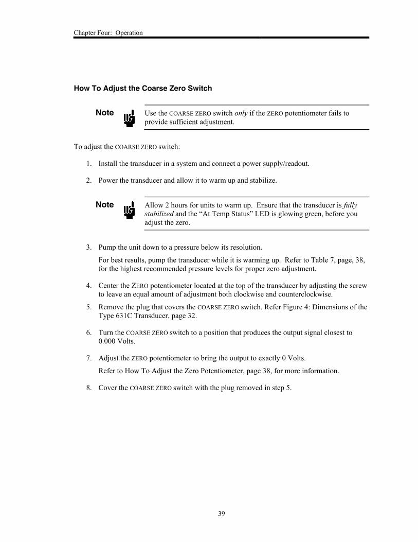
How To Adjust the Coarse Zero Switch
Note
Use the COARSE ZERO switch only if the ZERO potentiometer fails to
provide sufficient adjustment.
To adjust the COARSE ZERO switch:
1. Install the transducer in a system and connect a power supply/readout.
2. Power the transducer and allow it to warm up and stabilize.
Note
Allow 2 hours for units to warm up. Ensure that the transducer is fully
stabilized and the “At Temp Status” LED is glowing green, before you
adjust the zero.
3. Pump the unit down to a pressure below its resolution.
For best results, pump the transducer while it is warming up. Refer to Table 7, page, 38,
for the highest recommended pressure levels for proper zero adjustment.
4. Center the ZERO potentiometer located at the top of the transducer by adjusting the screw
to leave an equal amount of adjustment both clockwise and counterclockwise.
5. Remove the plug that covers the COARSE ZERO switch. Refer Figure 4: Dimensions of the
Type 631C Transducer, page 32.
6. Turn the COARSE ZERO switch to a position that produces the output signal closest to
0.000 Volts.
7. Adjust the ZERO potentiometer to bring the output to exactly 0 Volts.
Refer to How To Adjust the Zero Potentiometer, page 38, for more information.
8. Cover the COARSE ZERO switch with the plug removed in step 5.
Chapter Four: Operation
40
Heater Status LEDs and Heater Alarm Relay
The 631C transducer is designed to function at its specified operating temperature by maintaining
the sensor temperature within a tight range of the operating temperature. There are two status
LEDs, “Htr Fail Status” and “At Temp Status,” that provide a visual indication of the heater
condition. Since the operating temperature of the sensor is critical, the 631C unit contains a heater
alarm relay that monitors the performance of the sensor heater. In addition, the Interface (J1)
connector contains the heater alarm relay contact pins. (Refer Table 6: Pinout of the Interface
Connector (J1), page 34, for the pinout of the Interface (J1) connector and refer to Table 9, page
41, for a summary of the conditions determining the heater status LEDs and heater alarm relay
output.)
When power is applied to the unit, the heater receives full power and the temperature of the
sensor rises toward the nominal operating temperature. The heater alarm relay will be energized
to indicate that the heater is working. During the warm-up period, the “Htr Fail Status” LED will
be off and the “At Temp Status” LED will glow yellow.
When the actual temperature of the sensor is within the LED temperature window, 631C heater is
in control and the “At Temp Status” LED will glow green. The heater alarm relay will continue
to be energized and the “Htr Fail Status” LED will continue to be off. Note that the LED
temperature window is approximately within 8% of the operating temperature, 150C or 200C,
and is used for a gross indication the sensor is within acceptable limits. The actual operating
temperature of the sensor is maintained within a significantly tighter range.
If the heater control circuitry fails in a no-current failure mode, the sensor will begin to cool. At
this time, the “Htr Fail Status” LED will glow red and the heater alarm relay will be de-energized.
When the sensor temperature falls below the lower limit of the operating temperature LED
window, the “At Temp Status” LED will glow yellow.
If the heater control circuit fails in a always-‘On’ mode, the sensor will overheat. The “At Temp
Status” LED will glow yellow when the sensor temperature reaches the upper limit of the LED
temperature window, the “Htr Fail Status” LED will continue to be off and the heater alarm relay
will continue to be energized.
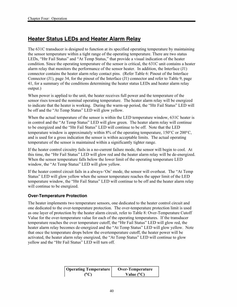
Over-Temperature Protection
The heater implements two temperature sensors, one dedicated to the heater control circuit and
one dedicated to the over-temperature protection. The over-temperature protection limit is used
as one layer of protection by the heater alarm circuit, refer to Table 8: Over-Temperature Cutoff
Value for the over-temperature value for each of the operating temperatures. If the transducer
temperature reaches the over temperature cutoff, the “Htr Fail Status” LED will glow red, the
heater alarm relay becomes de-energized and the “At Temp Status” LED will glow yellow. Note
that once the temperature drops below the overtemperature cutoff, the heater power will be
activated, the heater alarm relay energized, the “At Temp Status” LED will continue to glow
yellow and the “Htr Fail Status” LED will turn off.
Operating Temperature
(C)
Over-Temperature
Value (C)

Chapter Four: Operation
41
150 185
200 230
Table 8: Over-Temperature Cutoff Value
Conditions Determining Status LEDs and
Relay Output
At Temp
Status
LED
Htr Fail
Status
LED
State of Heater
Alarm Relay
Contacts
1. Power ON
2. Temp below lower limit of LED temperature window
3. Heater current ON
Yellow Off
Energized
Pin 13: Open
Pin 14: Closed
1. Power ON
2. Temp below lower limit of LED temperature window
3. Heater current OFF
Yellow Red
De-energized
Pin 13: Closed
Pin 14: Open
1. Power ON
2. Temp within LED temperature window
3. Heater current ON or OFF
Green Off
Energized
Pin 13: Open
Pin 14: Closed
1. Power ON
2. Temp above upper limit of LED temperature window
3. Temp below overtemperature cutoff
4. Heater current ON
Yellow Off
Energized
Pin 13: Open
Pin 14: Closed
1. Power ON
2. Temp above upper limit of LED temperature window
3. Temp below overtemperature cutoff
4. Heater current OFF
Yellow Red
De-energized
Pin 13: Closed
Pin 14: Open
1. Power ON
2. Temp above overtemperature
3. Heater current ON or OFF
Yellow Red
De-energized
Pin 13: Closed
Pin 14: Open
1. Power OFF Off Off
De-energized
Pin 13: Closed
Pin 14: Open
Table 9: Conditions and resulting status LEDs and heater alarm relay output.

Chapter Four: Operation
42
This page intentionally left blank.
Chapter Five: Optional Relay System
43
Chapter Five: Optional Relay System
General Information
The 631C transducer provides the option for two internally mounted trip point relays with user
adjustable pressure conditions that will energize each relay. The trip point direction – whether the
relay energizes above or below the selected pressure condition – is chosen using the appropriate
model code when purchasing the 631C transducer (refer to Appendix B: Model Code
Explanation, page 51). A visual indication of the status of each trip point relay is provided by a
dedicated LED that illuminates when the trip point relay is energized. The relay becomes de-
energized and the LED turns off when the pressure returns to the selected trip point value plus
hysteresis (refer to Trip Point Direction, page 44 for a description of how hysteresis affects the
relay switching).
The interface connector houses the contact pins of both trip point relays to equip the user with
remote indication of the relay status. The three pins of each relay produce an open/closed output;
for example, if Trip Point A is energized, pins 3 & 4 will be an open circuit. Refer to Table 6:
Pinout of the Interface Connector (J1), page 34, for the pinout of the Interface (J1) Connector.
Trip Point Parameters
Trip Point Values
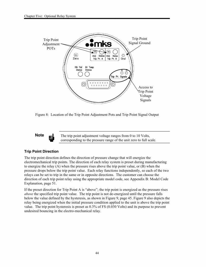
The trip point value is the pressure condition that each relay will become energized. The trip
point value of each relay can be adjusted individually using the trip point adjustment POTs.
These POTs are located on the top of the 631C unit, as shown on Figure 8, page 44, and labeled
as “Adj” above the corresponding “Trip Pt A” and “Trip Pt B” label. The trip point value can be
monitored by measuring the voltage between the trip point signal of interest and the ground
(labeled as “Trip Pt. Signals” and “Gnd”). A pair of 0.080 inch test point jacks must be used in
order to gain access to the trip point voltage signals. The trip point signal voltage ranges from 0
to 10 V, which corresponds to the pressure range of the unit from zero to full scale.
Chapter Five: Optional Relay System
44
Figure 8: Location of the Trip Point Adjustment Pots and Trip Point Signal Output
Note
The trip point adjustment voltage ranges from 0 to 10 Volts,
corresponding to the pressure range of the unit zero to full scale.
Trip Point Direction
The trip point direction defines the direction of pressure change that will energize the
electromechanical trip points. The direction of each relay system is preset during manufacturing
to energize the relay (A) when the pressure rises above the trip point value, or (B) when the
pressure drops below the trip point value. Each relay functions independently, so each of the two
relays can be set to trip in the same or in opposite directions. The customer can choose the
direction of each trip point relay using the appropriate model code, see Appendix B: Model Code
Explanation, page 51.
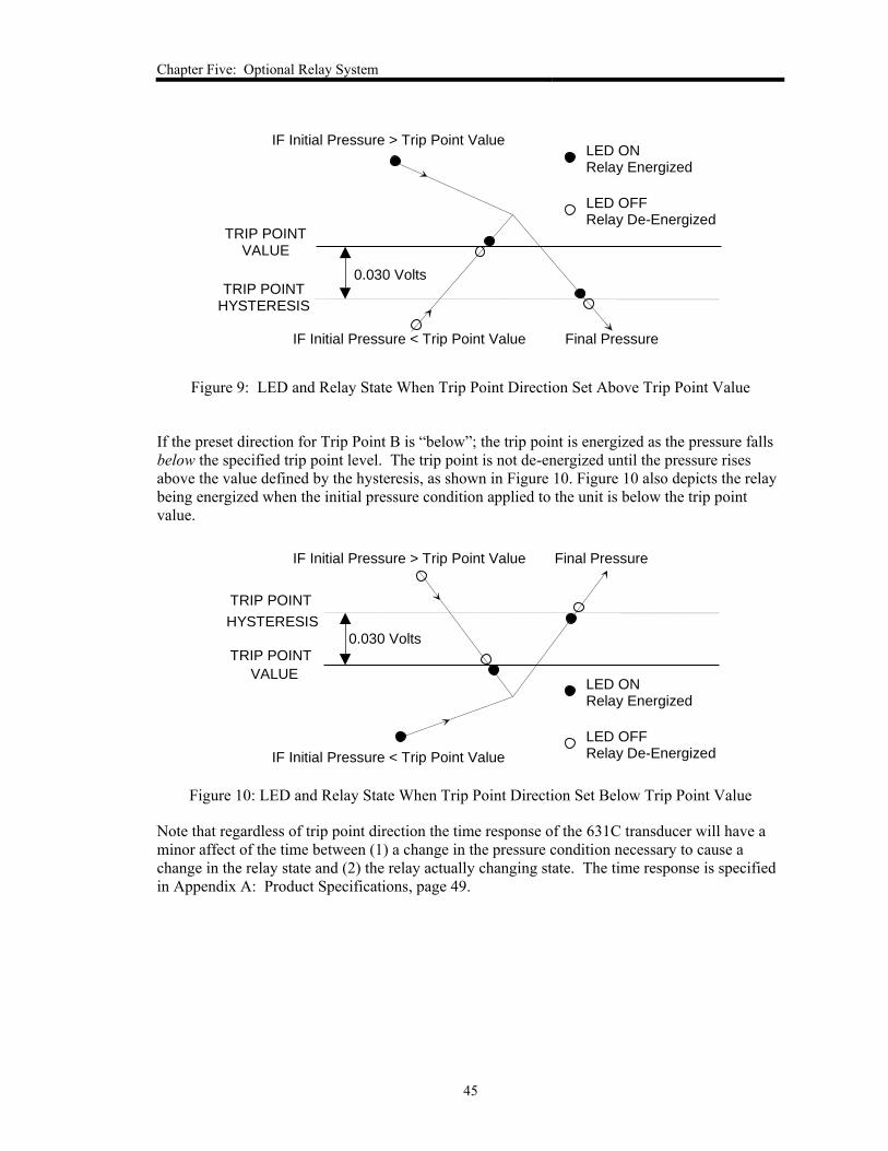
If the preset direction for Trip Point A is “above”; the trip point is energized as the pressure rises
above the specified trip point value. The trip point is not de-energized until the pressure falls
below the value defined by the hysteresis, as shown in Figure 9, page 45. Figure 9 also depicts the
relay being energized when the initial pressure condition applied to the unit is above the trip point
value. The trip point hysteresis is preset as 0.3% of FS (0.030 Volts) and its purpose to prevent
undesired bouncing in the electro-mechanical relay.
Trip Point
Adjustment
POTs
Trip Point
Signal Ground
Access to
Trip Point
Voltage
Signals
Chapter Five: Optional Relay System
45
IF Initial Pressure < Trip Point Value
TRIP POINTHYSTERESIS
TRIP POINTVALUE
0.030 Volts
LED ONRelay Energized
LED OFFRelay De-Energized
IF Initial Pressure > Trip Point Value
Final Pressure
Figure 9: LED and Relay State When Trip Point Direction Set Above Trip Point Value
If the preset direction for Trip Point B is “below”; the trip point is energized as the pressure falls
below the specified trip point level. The trip point is not de-energized until the pressure rises
above the value defined by the hysteresis, as shown in Figure 10. Figure 10 also depicts the relay
being energized when the initial pressure condition applied to the unit is below the trip point
value.
IF Initial Pressure > Trip Point Value
TRIP POINT
HYSTERESIS
TRIP POINT
VALUE
0.030 Volts
LED ONRelay Energized
LED OFFRelay De-EnergizedIF Initial Pressure < Trip Point Value
Final Pressure
Figure 10: LED and Relay State When Trip Point Direction Set Below Trip Point Value
Note that regardless of trip point direction the time response of the 631C transducer will have a
minor affect of the time between (1) a change in the pressure condition necessary to cause a
change in the relay state and (2) the relay actually changing state. The time response is specified
in Appendix A: Product Specifications, page 49.

Chapter Five: Optional Relay System
46
This page intentionally left blank.
Chapter Six: Maintenance and Troubleshooting
47
Chapter Six: Maintenance and Troubleshooting
General Maintenance
For best accuracy and repeatability, MKS recommends that you:
Zero the unit regularly
Follow the procedure described in How To Zero the Type 631C Transducer, page 37, on
a regular basis.
Schedule re-calibration annually
Follow an annual recalibration schedule, if no other time interval has been specifically
established.
Periodically check for wear on the cables and inspect the enclosure for visible signs of
damage
Chapter Six: Maintenance and Troubleshooting
48
Troubleshooting
High, Low, or Erratic Output, or No Output at All
Check the Interconnecting Piping
Be sure there are no leaks or blockage in the interconnecting piping
Look for sediment in the sensor process connection(s)
Remove the sediment by purging the connection(s) with a solvent appropriate for your
process.
Caution
Damage may occur to the sensor if the sediment is removed with a
harsh solvent, or by scraping. Therefore:
Do not scrape the inside of the process connection(s).
Only clean the process connection(s) with solvent appropriate
for your process.
Check the Wiring
Ensure the voltage to the transducer is ±15 VDC (±5%) @ 1.0 Amps
Verify that the total current being drawn by the manometer is within the specifications of
the power supply
Check the signal terminals for the correct polarity
Measure the loop impedance
Look for shorts, multiple grounds, and defective wire insulation
If the solutions presented in this chapter fail to resolve the problem, return the transducer to MKS
for servicing. When returning the instrument to MKS, please obtain an RMA Number (Return
Material Authorization Number) from the MKS Calibration and Service Center before shipping.
The RMA Number expedites handling and ensures proper servicing of your instrument.
Refer to the inside of the back cover of this instruction manual for a complete list of MKS
Calibration and Service centers.
Warning
All returns to MKS Instruments must be free of harmful, corrosive, radioactive, or toxic materials.
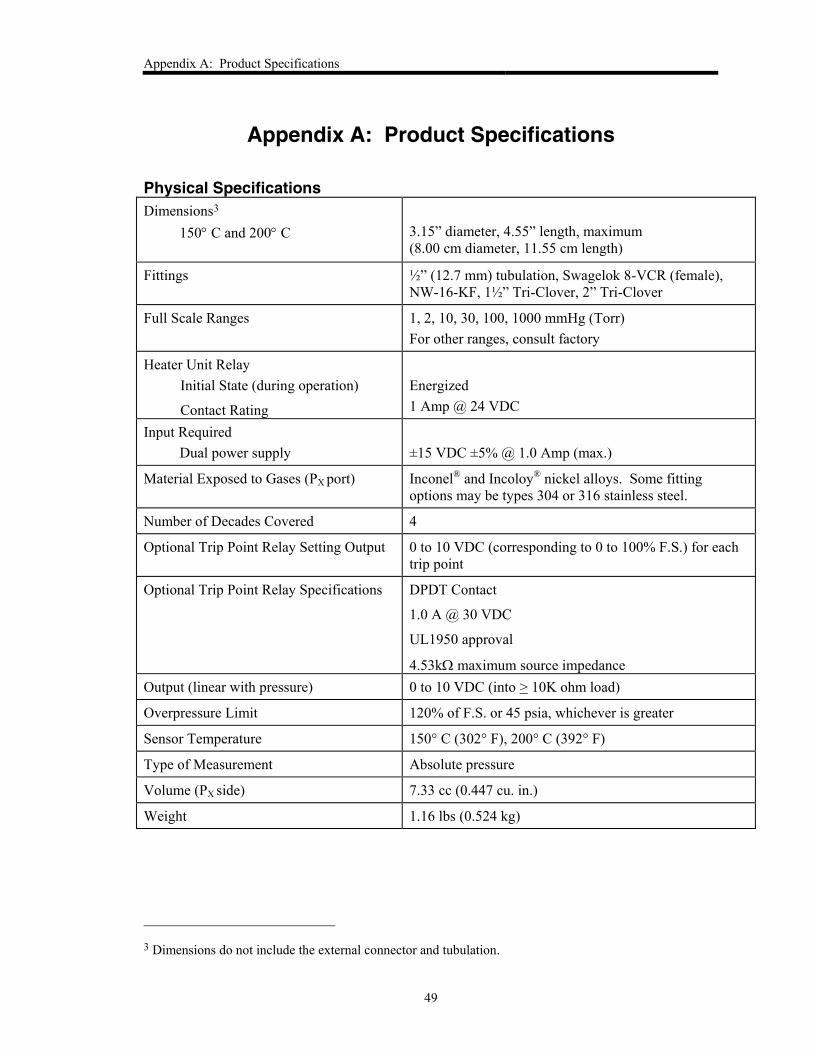
Appendix A: Product Specifications
49
Appendix A: Product Specifications
Physical Specifications Dimensions3
150 C and 200 C
3.15” diameter, 4.55” length, maximum
(8.00 cm diameter, 11.55 cm length)
Fittings ½” (12.7 mm) tubulation, Swagelok 8-VCR (female),
NW-16-KF, 1½” Tri-Clover, 2” Tri-Clover
Full Scale Ranges 1, 2, 10, 30, 100, 1000 mmHg (Torr)
For other ranges, consult factory
Heater Unit Relay
Initial State (during operation)
Contact Rating
Energized
1 Amp @ 24 VDC
Input Required
Dual power supply
±15 VDC ±5% @ 1.0 Amp (max.)
Material Exposed to Gases (PX port) Inconel® and Incoloy® nickel alloys. Some fitting
options may be types 304 or 316 stainless steel.
Number of Decades Covered 4
Optional Trip Point Relay Setting Output 0 to 10 VDC (corresponding to 0 to 100% F.S.) for each
trip point
Optional Trip Point Relay Specifications DPDT Contact
1.0 A @ 30 VDC
UL1950 approval
4.53k maximum source impedance
Output (linear with pressure) 0 to 10 VDC (into > 10K ohm load)
Overpressure Limit 120% of F.S. or 45 psia, whichever is greater
Sensor Temperature 150° C (302° F), 200° C (392° F)
Type of Measurement Absolute pressure
Volume (PX side) 7.33 cc (0.447 cu. in.)
Weight 1.16 lbs (0.524 kg)
3 Dimensions do not include the external connector and tubulation.
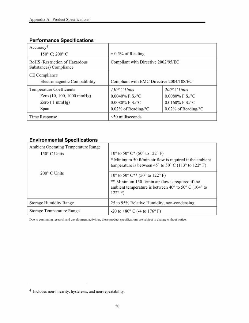
Appendix A: Product Specifications
50
Performance Specifications Accuracy4
150 C; 200 C
± 0.5% of Reading
RoHS (Restriction of Hazardous
Substances) Compliance
Compliant with Directive 2002/95/EC
CE Compliance
Electromagnetic Compatibility
Compliant with EMC Directive 2004/108/EC
Temperature Coefficients
Zero (10, 100, 1000 mmHg)
Zero ( 1 mmHg)
Span
150 C Units
0.0040% F.S./°C
0.0080% F.S./°C
0.02% of Reading/°C
200 C Units
0.0080% F.S./°C
0.0160% F.S./°C
0.02% of Reading/°C
Time Response <50 milliseconds
Environmental Specifications Ambient Operating Temperature Range
150 C Units
200 C Units
10° to 50° C* (50° to 122° F)
* Minimum 50 ft/min air flow is required if the ambient
temperature is between 45 to 50 C (113 to 122 F)
10° to 50° C** (50° to 122° F)
** Minimum 150 ft/min air flow is required if the
ambient temperature is between 40 to 50 C (104 to
122 F)
Storage Humidity Range 25 to 95% Relative Humidity, non-condensing
Storage Temperature Range -20 to +80 C (-4 to 176° F)
Due to continuing research and development activities, these product specifications are subject to change without notice.
4 Includes non-linearity, hysteresis, and non-repeatability.
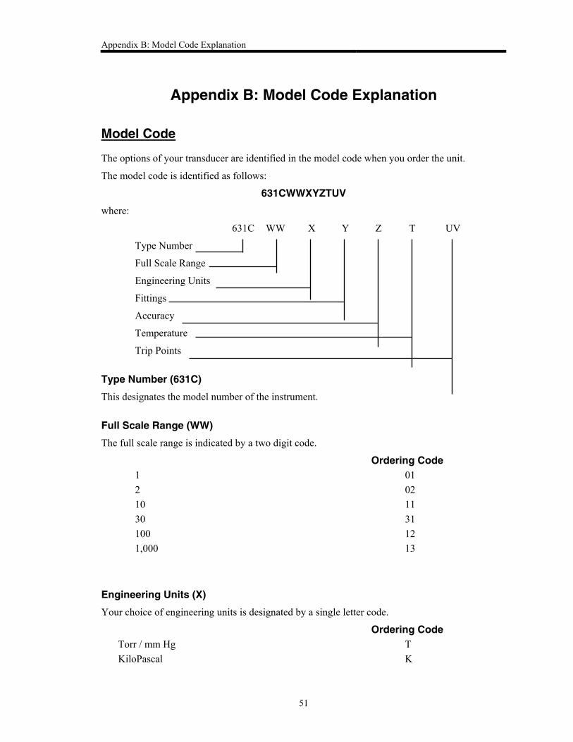
Appendix B: Model Code Explanation
51
Appendix B: Model Code Explanation
Model Code
The options of your transducer are identified in the model code when you order the unit.
The model code is identified as follows:
631CWWXYZTUV
where:
631C WW X Y Z T UV
Type Number
Full Scale Range
Engineering Units
Fittings
Accuracy
Temperature
Trip Points
Type Number (631C)
This designates the model number of the instrument.
Full Scale Range (WW)
The full scale range is indicated by a two digit code.
Ordering Code 1 01
2 02
10 11
30 31
100 12
1,000 13
Engineering Units (X)
Your choice of engineering units is designated by a single letter code.
Ordering Code
Torr / mm Hg T
KiloPascal K
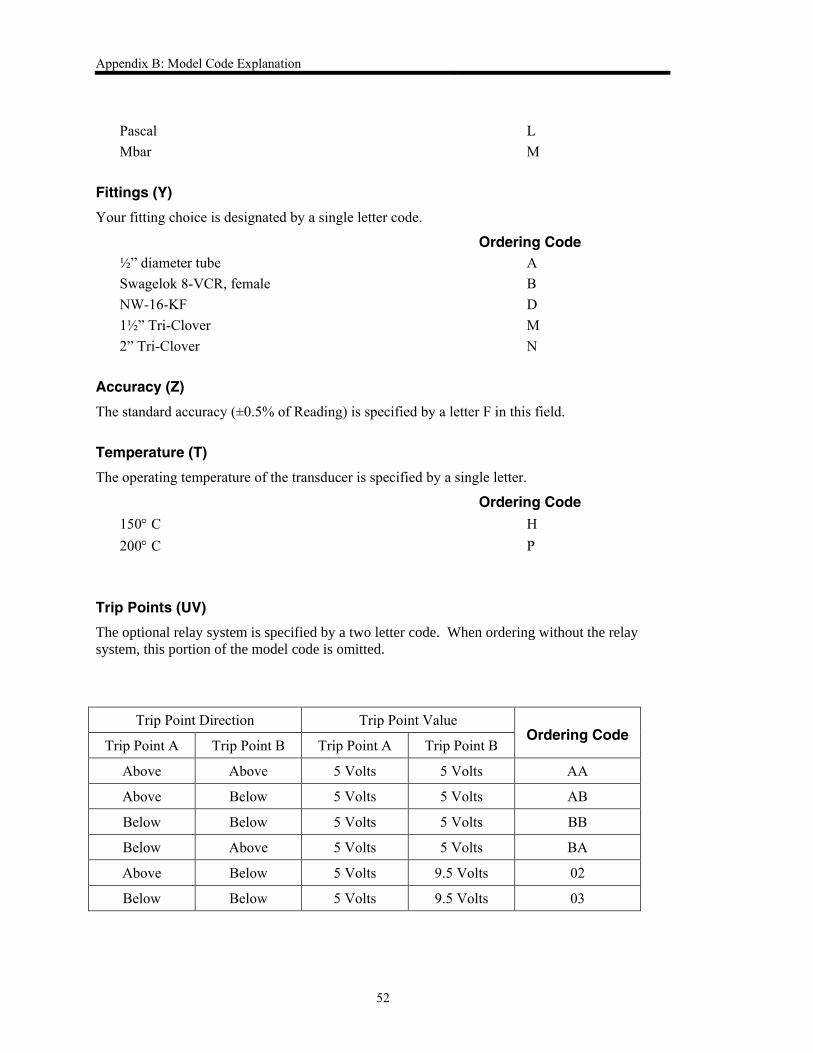
Appendix B: Model Code Explanation
52
Pascal L
Mbar M
Fittings (Y)
Your fitting choice is designated by a single letter code.
Ordering Code
½” diameter tube A
Swagelok 8-VCR, female B
NW-16-KF D
1½” Tri-Clover M
2” Tri-Clover N
Accuracy (Z)
The standard accuracy (±0.5% of Reading) is specified by a letter F in this field.
Temperature (T)
The operating temperature of the transducer is specified by a single letter.
Ordering Code
150 C H
200 C P
Trip Points (UV)
The optional relay system is specified by a two letter code. When ordering without the relay
system, this portion of the model code is omitted.
Trip Point Direction Trip Point Value Ordering Code
Trip Point A Trip Point B Trip Point A Trip Point B
Above Above 5 Volts 5 Volts AA
Above Below 5 Volts 5 Volts AB
Below Below 5 Volts 5 Volts BB
Below Above 5 Volts 5 Volts BA
Above Below 5 Volts 9.5 Volts 02
Below Below 5 Volts 9.5 Volts 03

Appendix B: Model Code Explanation
53

Appendix B: Model Code Explanation
54
This page intentionally left blank.
Index
55
Index
A
Accuracy, 17, 50, 52
Air flow, 24, 25, 50
Alarm, heater, 40
C
Cables, 17, 22, 23
CE compliance, 50
Connectors, 30, 31, 33
Customer support, 18
D
Dimensions, 32, 49
E
Environmental, 24, 25, 50
F
Fittings, 27, 49, 52
Full scale range, 17, 49, 51
G
Grounding, 23
H
Heater fail relay, 40, 41, 49
Humidity
storage, 24, 50
I
Input power, 17, 23, 48, 49
Interface cables, 17, 22
L
Labels, 34, 35
hot, 35
serial number, 35
wiring diamgram, 34
M
Maintenance, 47
Manual organization, 18
Model code, 51
Mounting, 25, 26
O
Output signal, 17, 29, 34, 49
Overpressure, 17, 23, 34, 49
Overtemperature, 40, 41
P
Pinout, connector, 33, 43
Piping considerations, 27
Port connections, 26, 27
Power supply
current rating, 23, 48
wiring, 23, 34
Power supply, wiring, 34
R
Relay
heater fail, 17, 40
trip point, 17, 29
Returning the product, 18, 21

Index
56
S
Sensor, 17, 26, 29
Sensor fittings, 27
Setup, 25, 26
Signal conditioner, 17, 29
Standard sensor fittings, 27
T
Temperature
coefficients, 50
operating, ambient, 24, 25, 50
operating, sensor, 17, 40, 49, 52
storage, 24, 50
Time response, 50
Trip point relay system, 17, 29, 43
direction, 43, 44, 53
hysteresis, 45
value, 43, 53
Troubleshooting, 48
V
Ventilation, 24, 25, 50
Vibration, 23, 26
W
Warm up, 17, 23
Z
Zero adjustment
coarse zero switch, 37, 39
zero pot, 37, 38


